grain bin storage structures - chief agri/industrial bins... · grain bin storage structures n al...
TRANSCRIPT

GRAIN BIN STORAGE STRUCTURES
OP
ER
AT
IO
N M
AN
UA
L
P/N
349402 R
ev 0

Chief Industries, Inc. 800-359-7600 TOC – 349402 Page 2
C H I E F I N D U S T R I E S , I N C . – A G R I / I N D U S T R I A L D I V I S I O N
Operation Manual
This manual is for the design, operation and maintenance of Chief Grain Bins effective 1/1/2016.
Chief Industries, Inc. 4400 East 39th Street • PO Box 848
Kearney, NE 68847 Phone 800.359.7600
For more information about Chief Industries, Inc. and additional products or services please visit our website
www.agri.Chiefind.com
WARNING: Improper installation, adjustment, alteration, service or
maintenance can cause property damage, injury or death. Read the
installation, operating and maintenance instructions thoroughly
before installing or servicing this equipment.
This symbol means “Attention! Be Alert! Your Safety Is At Stake!” The safety alert symbol identifies safety messages for your storage structure and aeration floor. Ensure you are familiar with the messages identified for you with the safety alert symbol. When you see this symbol, be alert to the possibility of serious injury or death. Follow the safety instructions given in this manual and for your bin and aeration floor.
Danger: Indicates an imminently hazardous situation which, if not avoided, will result in death or serious injury.
Warning: Indicates a potentially hazardous situation which, if not avoided, could result in death or serious injury and property damage.
Caution: Indicates a potentially hazardous situation which, if not avoided, may result in minor or moderate injury. It may also be used to alert against unsafe practices.

Chief Industries, Inc. 800-359-7600 TOC – 349402 Page 3
Table of Contents
Introduction ........................................................................... 4
Model Number Description .............................................................. 4
Before You Begin ................................................................. 5
Safety and Precautions ..................................................... 6
General Design Information ........................................... 10
Storage Structure Usage ............................................................... 10
General Contractor Responsibilities .............................................. 11
Concrete Design and Construction ....................................................... 11
Accessory Equipment .......................................................................... 11
Field Modifications and Installation Defects .......................................... 12
Roof Design Information ............................................................... 12
J-Rib Roof Design ................................................................................ 12
V-Rib Roof Design ............................................................................... 13
Roof Peak Service Loads ..................................................................... 13
Stirring Devices ............................................................................. 14
Continuous Flow Equipment ......................................................... 14
Ventilation ..................................................................................... 15
Fans and Transitions..................................................................... 15
Heaters ......................................................................................... 16
Aeration Floors .............................................................................. 16
Temperature Cables ..................................................................... 16
Grain Storage Operations ............................................... 17
Bin Loading ............................................................................... 17
Bin Unloading (Reclaim) ....................................................... 19
Bin Side Draw Unloading ...................................................... 20
Maintenance: ....................................................................... 23
Manual Revisions ............................................................... 23
STANDARD LIMITED WARRANTY......................................... 24

G R A I N B I N S
Chief Industries, Inc. 800-359-7600 INTRODUCTION -349402 Page 4
Introduction
Thank you for purchasing a Chief grain bin. Proper installation and operation will ensure you the best overall experience with your grain bin and guarantee smooth operation.
This proprietary information is loaned with the expressed agreement that the drawings and information therein contained are the property of Chief Industries, Inc. and will not be reproduced, copied, or otherwise disposed of, directly or indirectly, and will not be used in whole or in part to assist in making or to furnish any information for the making of drawings, prints or other reproduction hereof, or for the making of additional products or equipment except upon written permission of Chief Industries, Inc. first obtained and specific as to each case. The acceptance of this material will be construed as an acceptance of the foregoing agreement. The technical data contained herein is the most recent available at the time of publication and is subject to modification without notice. Chief Industries, Inc. reserves the right to modify the construction and method of operation of their products at any time without any obligation on their part to modify any equipment previously sold and delivered.
Model Number Description
The model nomenclature distinguishes the application of the grain bin. The information includes a designation of the applicable structure diameter, eave height, roof design and design criteria utilized. The definition of the model number nomenclature is as follows:
Example: CB 24 - 18 - J Rib - SZA
(a) (b) - (c) - (d) - (e)
(a) CB = Chief Bin (b) 24 = Grain Bin Diameter Where: 24 = 24 sheets in circumference (c) 18 = Grain Bin Eave Height Where: 18 = 18 sheets in height (d) J Rib = Roof Design Type Where: J Rib = J Rib design Where: V Rib = V Rib design
(e) Grain Bin Design Criteria for seismic and wind

G R A I N B I N S
Chief Industries, Inc. 800-359-7600 INTRODUCTION -349402 Page 5
Before You Begin
Read this manual thoroughly before using this grain bin. Keep this manual in a location for quick access and reference.
The installation of the grain bin may require field fastening for some components. When using a cutting torch or welding galvanized material, the possibility of developing toxic fumes will exist. Provide adequate ventilation and respiratory protection when using this type of equipment during installation.
Special Service Note: If you are unable to remedy any service problem after thoroughly studying this manual, contact the dealer from whom you purchased the unit. Your dealer is your first line of service. The following information is required for service:
1. Bin model number: __________________________________
2. Diameter and eave height of bin: _________________________
3. Grain depth: _________________________________________
4. Type of grain stored: ___________________________________
5. Dealer purchased from: _________________________________
6. Dealer address and phone number: ________________________
7. Date purchased: _______________________________________
8. Service contractor:
a. Name: _____________________________________________
b. Address: ____________________________________________
c. Phone: _____________________________________________
WARNING: Water Sensitive Materials - Read this notice carefully
Bundles must be inspected and carrier advised immediately if damage is noted. White rust will attack painted as well as galvanized sheeting. If water has entered a bundle or if condensation has formed between sheets, the bundle must be opened, the sheets separated and all surfaces dried.
If sheets are to be installed within 10 days:
Store bundled sheets of the ground high enough to allow air circulation beneath bundle and to prevent water from entering. Store 1 end at least 8” (20.32cm) higher than the opposite end. Support long bundles in the center. Prevent rain from entering the bundle by covering with a tarpaulin, making
provision for air circulation between the draped edges and the ground. Note: Do not wrap in plastic.
If sheets are not to be installed within 10 days:
Provide inside dry storage. Storage beyond 6 months is not recommended. If white rust is apparent upon receipt of shipment, notify Chief immediately. Damage to sheets, resulting from improper storage, will be the responsibility of the receiver.

G R A I N B I N S
Chief Industries, Inc. 800-359-7600 OPERATIONS -349402 Page 6
Safety and Precautions
Your safety and the safety of others is a primary concern to Chief Industries, Inc. This manual was written to assist in the safe installation and operation of the grain bin.
It is your responsibility as the owner, builder, operator, or supervisor to know what specific requirements, precautions and hazards exist and to make these known to all personnel working with equipment or on the jobsite so that they can observe any necessary safety precautions.
All personnel, including the installation crew, must read and understand the information contained in this manual before starting construction. Chief Industries, Inc. is not responsible or liable for the misuse of equipment or operation of personnel or equipment in an unsafe manner.
Chief Industries, Inc. assumes no liability with respect to proper construction and inspection, assembly, or use of its products established under applicable laws, all of which is the sole responsibility of the purchaser and those authorized for the installation.
Follow all local and federal safety laws and regulations. Verify that all equipment and personnel conform to any applicable jurisdiction regulations.
Work Area Safety Statement
To ensure the safety of all individuals in the work area, only authorized and trained persons shall install, and maintain the grain bin.
Under no circumstances should unauthorized individuals be allowed to trespass or be present in the work area.
It shall be the duty of all operators to ensure that the work area is clean, organized and kept free of all debris and tools that might cause an accidental tripping or falling hazard.
Special care should be taken when working from unsafe heights. Common sense dictates that when conditions such as rain or wind prohibit the safe use of equipment, the installation be discontinued.
Chief Industries, Inc. strongly recommends that equipment meeting the current specifications be used, whether the individual operator is required by law to do so or not. Proper climbing equipment and a secured safety harness should be used at all times when performing operations work, installation or maintenance.
Field modifications without the authorization of the manufacturer may present unknown dangers to the operator and must be avoided.
Auxiliary Equipment Safety
You may decide to purchase and install “auxiliary equipment” made by other manufacturers. Chief Industries, Inc. has no control over the design and manufacture of this equipment. In view of this, at a minimum, we suggest you do the following:
1. Obtain, read and understand the instructions and safety cautions of the auxiliary equipment
manufacturer. Be certain that all equipment is installed in agreement with those instructions.

G R A I N B I N S
Chief Industries, Inc. 800-359-7600 OPERATIONS -349402 Page 7
2. Check with Chief Industries, Inc. to verify that your system is designed to support any
additional loads supplied by the auxiliary equipment.
3. Obtain any applicable safety decals from the manufacturer and make certain they are
displayed in a visible location.
4. Make certain that all electrical equipment is properly installed and grounded by a qualified
electrician.
5. Check availability and operation of electrical lock out and emergency stop systems.
6. Be certain that all guards and shields are securely in place.
7. Store all operation / maintenance manuals in a safe place for future use.
Grain Bin Safety
Heed the following warnings:

G R A I N B I N S
Chief Industries, Inc. 800-359-7600 OPERATIONS -349402 Page 8

G R A I N B I N S
Chief Industries, Inc. 800-359-7600 OPERATIONS -349402 Page 9

G R A I N B I N S
Chief Industries, Inc. 800-359-7600 OPERATIONS -349402 Page 10
General Design Information
All Chief grain bins are designed for storage and handling of the following densities of grain:
49.5 PCF (793 kg/m3) free flowing grain
52.5 PCF (841 kg/m3) compacted grain @ 6%
Note: Grain fill level shall not exceed a height of 1.0" (2.54cm) below the roof eave.
Storage of products other than grain, products heavier than 49.5 PCF (793 kg/m3), products having unusual flow characteristics, or products with unusual corrosive properties must be approved by Chief Industries Inc. engineering department prior to quoting. Storage of non-flowing products such as soybean meal or meat scraps in a standard designed bin will void the warranty.
For the grain bin, each individual sidewall ring has been designed to accommodate the vertical and horizontal wall loads imposed by the stored grain. Sidewall sheeting gauge and design strength for each ring is individually analyzed for all bin sizes. Sidewall stiffener gauges and design strength is individually determined for the full sidewall height range. All steel materials are purchased in accordance with the applicable ASTM Standard.
All bolted connections are designed using high strength bolts which meet the specifications of the applicable ASTM or SAE standard.
All grain bins must be filled uniformly at the center and unloaded thru the center discharge only, until grain no longer flows by gravity. Grain bins filled or emptied off-center will void the warranty; with the exception of approved side draw unload systems.
All galvanized steel used for storage and drying bins conform to ASTM specification A653 with the galvanized coating to ASTM specification A924.
Galvanized coating type G-115 specifies galvanization of 1.15 oz/ft2 (Z350; 350 gm/m2) total for both sides in the following materials:
22 Gage thickness & lighter = Commercial Steel Type A, 33ksi min yield (grade 230)
18 & 20 Gage thickness = Structural Steel Grade 40, Class I; 40ksi min yield (grade 275)
17 Gage thickness & heavier = Structural Steel Grade 55, Class I; 55ksi min yield (grade 340)
Storage Structure Usage
Chief unstiffened bin series (CBU and CBUE) with eave heights of up to 7 rings are designed for storage and drying of common small grains. Eave heights of 8 rings and above are to be used for grain storage only.
The Chief stiffened bin series #5 thru #16 may be used for all common drying applications. If stirring devices consisting of more than six down augers are to be used, contact Chief for recommendations. The stiffened bin series must be used when devices with stirring or down augers are installed.

G R A I N B I N S
Chief Industries, Inc. 800-359-7600 OPERATIONS -349402 Page 11
General Contractor Responsibilities
It is the responsibility of the general contractor to insure that the complete storage structure system is constructed with quality workmanship and that all equipment is installed per the respective manufacturer's instructions. This includes the following:
Bin
Foundation
Base sealing
Grain transport equipment
Aeration equipment
Accessory equipment
In addition, the general contractor is responsible for the fitness of use of any system which he constructs. All accessory equipment incorporated into the system, from each respective equipment manufacturer, should be approved for the intended use.
Concrete Design and Construction
Suggested foundation designs based upon the allowable soil bearing capacity of the undisturbed soil should be certified by a licensed engineering firm. Using soil borings to determine the allowable soil bearing capacity, a professional engineer will need to be employed by the contractor to design the foundation and floor slab accordingly.
All suggested foundation designs must be approved by a licensed engineer in order to meet local governing building codes and local soil and weather conditions. Wall loads and floor pressure for Chief grain bins are available from Chief Industries, Inc., upon request.
Note: The finished floor surface must be level at the sidewall sheet location. Low spots in the perimeter wall elevation without adequate shimming can cause structural damage to the bin sidewall. Faulty concrete or missing shims will void the warranty.
The suggested concrete foundation designs must not be used in conjunction with unload and aeration tunnels. Concrete and reinforcing bar requirements must be determined by a certified professional engineer. The design must consider soil bearing capacity, soil consolidation, footing requirements, tunnel requirements and the interaction of all foundation components under loaded condition. Non-uniform settlement of the foundation can cause severe structural damage to the storage structure and foundation. An improperly designed or constructed foundation will void all aspects of the warranty. It is the responsibility of the general contractor to insure that an adequate foundation is provided for the grain bin.
Accessory Equipment
Accessory equipment can be installed with the grain bin; however certain limitations and special considerations must be followed in order to maintain the warranty.
All accessory equipment should be installed and maintained in accordance with each individual supplier’s installation and operation instructions. However, if any sidewall penetrations or other modifications to the Chief standard design are required, refer to the installation manual and contact Chief for special recommendations.

G R A I N B I N S
Chief Industries, Inc. 800-359-7600 OPERATIONS -349402 Page 12
Note: Do not modify the storage structure design without Chief approval. It is the responsibility of the general contractor to insure that all equipment is properly installed and that the equipment is compatible with the intended use. A qualified electrician should be contracted to complete all electrical wiring and servicing.
Field Modifications and Installation Defects
Chief Industries, Inc. assumes no responsibility for field modifications or installation defects which result in structural damage or storage quality problems. If any field modifications are necessary which are not specifically covered by the contents of the installation manual, contact Chief for approval. Any unauthorized modification or installation defect which affects the structural integrity of the grain bin will void the warranty.
Roof Design Information
All Chief Industries grain bin roof structures are designed to withstand normally anticipated
environmental and service conditions per the specified design code (UBC or IBC). Note: Roof peak loads in excess of the specified rating can cause structural damage and will void all warranties.
J-Rib Roof Design
The CB5 thru CB34 grain bins are designed with a 30 degree roof slope. The CB9 thru CB11 designs incorporate a roof structural bridging ring. These roofs have 4 roof panels per sidewall sheet.
The CB12 thru CB34 grain bin roofs utilize a complete structural framing system which supports loads independent of the roof panels. CB22 thru CB34 feature a split roof panel design.
The CB5 thru CB34 designs utilize a working ring that provides a continuous ring around the center peak and is attached with heavy gauge brackets located on top of roof ribs, near the roof cap.
For all roofs incorporating a J-Rib panel design, various peak ring sizes and peak loading options are available.
Peak Ring Peak Load Ground Snow Load
30” (76.2cm) 1,000lbs (453kg) 17 psf
40” (101.6cm) 10,000lbs (4,535kg) 25 psf
72” (182.8cm) 12,000lbs (5,443kg) 30 psf
144” (365.7cm) 16,000lbs (7,257kg) 40 psf
25,000lbs (11,339kg) 50 psf
30,000lbs (13,607kg) 60 psf
40,000lbs (18,143kg)
50,000lbs (22,679kg)
Note: The peak load capacities listed must not be exceeded. If your application will exceed the listed values, contact Chief Industries Inc. for recommendations.

G R A I N B I N S
Chief Industries, Inc. 800-359-7600 OPERATIONS -349402 Page 13
V-Rib Roof Design
The CBU & CBUE #5 thru #16 grain bins are designed with a 30 degree roof slope. These roofs have 4 roof panels per sidewall sheet. 1 piece roof panels are standard for all roofs and feature 2.50” (6.35cm) deep ribs for the #5 thru #12 roofs, and 4.0” (10.16cm) deep ribs for the #14 thru #16 roofs. An optional eave seal part is available if desired.
Roof rib fasteners utilize JS500 zinc plated hex head bin bolts. This hardware enables quick assembly of the bin roof and a positive, structural and weather resistant rib to rib connection.
Heavy gauge galvanized eave clips bolt directly to roof panel and wall sheet. These clips are adjustable with slotted holes to raise or lower roof as desired. "Hurricane Clips" are standard on all bins to strengthen against wind forces.
The #5 thru #16 roofs utilize a working ring that provides a continuous ring around the center peak and is attached with heavy gauge brackets located on top of roof ribs, near the roof cap.
The V-Rib roof design incorporates an optional exterior roof bridging ring on #7 thru #9 roofs. The exterior roof bridging ring is standard on all #10 thru #12 roofs. 2 outside roof bridging rings are standard for #14 thru #16 roofs. Rings are fabricated from heavy gauge tube. Threaded connectors expand to position the ring in place.
All V-Rib roof designs are referred to as “unstructured” and incorporate the following peak load ratings:
Bin Size Peak Ring Peak Load Ground Snow Load
CB5 to CB7 30” (76.2cm) 3,500lbs (1,587kg) 17 psf
CB8 to CB12 30” (76.2cm) 6,000lbs (2,721kg) 17 psf
CB14 to CB16 40” (182.8cm) 8,500lbs (3,855kg) 17 psf
Note: The peak load capacities listed must not be exceeded. If your application will exceed the listed values, contact Chief Industries Inc. for recommendations.
Roof Peak Service Loads
For standard bin models towers located between the bins should support overhead equipment such as conveyors, augers, and catwalks. The bin walls or roof should not support the load from these items. When an alternate site design is required, the grain bin can be specifically designed to support concentrated loads at the peak or eave of the roof with upgraded design stiffeners to support the overhead load.
When determining the service loads on the roof peak, the weight of all accessory equipment suspended or supported by the peak should be considered. The weights should be calculated using the equipment dead load plus the live load from the grain in transit.
For example, the weight of an overhead conveyor should include the catwalk, conveyor head assembly, motors, drives, downspouts, discharges and weight of grain when in operation. If conveyor and catwalk design is such that snow build up is likely during winter months, snow load

G R A I N B I N S
Chief Industries, Inc. 800-359-7600 OPERATIONS -349402 Page 14
must be added in the peak load calculation. If a temperature cable is suspended from peak add 1000 lbs. (452 kg.) per 40 foot (12.2 m) of cable length to the peak's service load. Interpolate value for intermediate cable lengths (example: 60 foot (18.3 m) cable would exert 1500 lbs. (680 kg), of load).
Note: Do not allow excessive snow and ice to accumulate on any portion of the roof, potentially causing excessive roof loading and structural damage.
Note: Roof peak overloading can cause structural damage to the bin roof. Roof loads in excess of the specified peak rating will void the warranty.
Stirring Devices
Stirring devices can be installed in any drying bin, with the limitations discussed previously. The bin storage capacity will be reduced when installing a stirring device. Drying bin storage capacities listed in the Chief catalog should be used with the additional capacity reduction for the down auger drive unit clearance. Inside ladders may require reduced length brackets for wall attachment to provide the clearance required for the stirring device.
CAUTION: The grain level must not be filled above the stirring device. Grain pressure on the stirring device could cause roof or stirring device damage. Do not operate augers near the sidewall to prevent sidewall damage.
Down augers may require shortening in order to provide minimum floor clearance of 3"-5" (76mm -127 mm) or additional clearance for sweep augers. Always follow the manufacturer down auger shortening procedure.
Continuous Flow Equipment
Re-circulators can only be installed in stiffened CB grain bins. These devices should be installed as instructed by the manufacturer and with the following additional considerations:

G R A I N B I N S
Chief Industries, Inc. 800-359-7600 OPERATIONS -349402 Page 15
1. Consult floor manufacturer for recommended floor reinforcing measures at base of re-circulator.
2. If transfer auger exits thru roof panels, provide sealant around auger tube to prevent water leakage.
3. The weight of the transfer auger must not be supported by the roof panels. The transfer auger
should be supported by the re-circulator boot and an adjacent bin or independent support.
Ventilation
Any grain bins using forced air for aeration or drying must be provided with sufficient exhaust or intake vents to prevent excessive internal pressures, either positive or negative. The vent supplier should be consulted for ventilation requirements on each project, with the specific storage structure size, grain type and depth, fan size and floor type taken into consideration. Typically 1 sq ft (.09 sq meter) of exhaust area is required for every 1,000 cfm (28.31 cubic meters per minute) of exhaust. Chief does not recommend the use of negative aeration systems. In the event that negative aeration is to be used, the intake vent requirement should be sized for the storage structure in the empty condition.
Note: Roof vents must be open and free of debris or other obstructions prior to operation of the aeration fans.
Note: Powered fans should not be operated when ambient temperature is below 35 degrees Fahrenheit (2 degrees Celsius) due to the potential of vent icing. Obstructed or iced vents can significantly increase the internal to external pressure differential and could result in structural damage to the grain bin.
Note: High unloading rates can create a vacuum inside the grain bin. If unloading rates exceed 5,000bph (125mtph) a minimum of 1 free intake vent (goose neck is recommended) must be installed. 1 unobstructed standard Caldwell bin vent will provide adequate venting for an unloading rate of up to 80,000bph (2,000mtph). If substantially higher unloading rates are needed please contact Chief for a recommended venting requirement.
Fans and Transitions
Aeration fans should be sized in accordance with Chief's engineering specifications for each specific grain bin.
All fans must be installed per Chief's recommendations and leveled prior to operation. A qualified electrician should be contracted to complete all electrical wiring and servicing.
The transition thru the bin wall must be thoroughly sealed around the outside of the transition entrance collar to prevent airflow leakage. Use of caulking in combination with flashing provided by the transition manufacturer is recommended. If the transition interrupts a stiffener line, the special

G R A I N B I N S
Chief Industries, Inc. 800-359-7600 OPERATIONS -349402 Page 16
transition stiffener available from Chief must be installed as described in the installation manual. In addition, if the transition enters thru the bottom sidewall sheet (full floor aeration and tube aeration), adequate reinforcing of the bottom sidewall sheet must be added, contact Chief for recommendations. Standard drying bins do not require reinforcing of bottom sidewall sheet as long as transition enters below the false floor level.
Heaters
The heater unit must be properly matched with the fan size to be used. Heater unit and fan must be compatible, and it is recommended that both units be supplied by the same manufacturer to insure compatibility and safety. Heater unit installation and servicing should only be completed by personnel properly trained by the manufacturer of products being used. The fan and heater need to be located on the bin to assure uniform airflow to the bin. The units should be located at a position that is opposite (180 degrees) from the outlet of the unload tube.
DANGER: Fuel tanks, lines and all valves must be compatible with the type of fuel to be used.
Failure to use certified fuel tanks, lines or valves can result in death or severe personal injury.
DANGER: Never use anhydrous ammonia tanks or improperly modified fuel tanks for L.P. gas
storage.
DANGER: L.P. fuel flow control regulators must be installed as recommended by heater unit
manufacturer.
DANGER: Natural gas flow regulators at the service entrance must be installed by natural gas
supplier and must not be modified.
The drying temperature should be established based on the type of grain to be dried. Excessive heat can result in grain damage, over-drying and potential grain fires. For optimum temperature recommendations, contact Chief Industries Inc.
Aeration Floors
Chief recommends the use of channel lock floors with steel supports for full floor drying applications. The floor layout support spacing must be followed for the particular bin being constructed. Floor supports, fan locations and unload tube should be oriented as shown in the aeration layout supplied by Chief to provide optimum airflow movement.
1. Commercial drying applications (floors loaded and unloaded more than once per year) require 18
gage channel lock floors.
2. Grain depths 60' (18.3 m) to 89’ (27.1 m) require 18 gauge channel lock floors
3. Grain depths 90’ (27.4 m) to 110’ (33.5 m) require 16 gauge channel lock floors.
Temperature Cables
Temperature cables can be installed in all standard Chief grain bins. Refer to the installation manual for the correct quantity and location of temperature cables for the size of each grain bin.
Temperature cable support kits supplied by Chief are available and must be used whenever temperature cables are installed. Follow the temperature cable manufacturer's recommendations for installation of the cables and shortening temperature cables if required. Verify adequate clearance

G R A I N B I N S
Chief Industries, Inc. 800-359-7600 OPERATIONS -349402 Page 17
for sweep augers or other internal equipment and provide adequate sealant where the temperature cable lead wire exits the storage structure.
Note: Support of temperature cables by any method other than a Chief support kit may cause structural damage to the roof structure and will void the warranty. All temperature cables should be secured to the floor to prevent the cable from drifting towards the sidewall during filling. The use of light twine or monofilament line secured to a recessed anchor is recommended.
Note: “Structured” roofs are designed for a maximum load of 2,000 lbs. per temperature cable. If this load is exceeded, this may cause structural damage to the roof and will nullify the warranty.
Grain Storage Operations
Bin Loading
Standard commercial grain bins (CB18 and larger) can be loaded at a rate below 40,000 bushels per hour. If a loading rate of 40,000 bushels per hour or greater is required, or the grain bin is smaller than a CB18 and requires a loading rate of 40,000 bushels per hour, contact Chief for upgrade recommendations.
Center filling thru the peak opening is recommended for all grain bins. Off center loading can create unequal pressures on the sidewall and will result in structural damage. If spouting is to be used, it is recommended that a dead head or cushion box be used to promote uniform filling. Also, the use of spreaders or splash plates are recommended for distributing the grain fines, promoting uniform air flow thru grain and leveling the grain peak.
Note: Do not overfill the grain bin. Overfilling can cause structural damage to the roof and creates improper airflow and ventilation issues. The maximum grain level is 1” (2.54cm) below the roof eave.

G R A I N B I N S
Chief Industries, Inc. 800-359-7600 OPERATIONS -349402 Page 18
The approximate spouting length from the bin peak is shown in the following chart. The angle of repose for filling the grain must be considered to prevent overflow above the eave.
Bin Size Roof Type Peak Opening
28 Degree Fill Angle
22 Degree Fill Angle
5 V-Rib 30” (76.2cm) 7” (17.7cm) 16” (40.6cm)
J-Rib 30” (76.2cm) 7” (17.7cm) 13” (33.0cm)
6 V-Rib 30” (76.2cm) 7” (17.7cm) 20” (50.8cm)
J-Rib 30” (76.2cm) 7” (17.7cm) 17” (43.1cm)
7 V-Rib 30” (76.2cm) 7” (17.7cm) 23” (58.4cm)
J-Rib 30” (76.2cm) 7” (17.7cm) 20” (50.8cm)
8 V-Rib 30” (76.2cm) 7” (17.7cm) 26” (66.0cm)
J-Rib 30” (76.2cm) 7” (17.7cm) 23” (58.4cm)
9 V-Rib 30” (76.2cm) 8” (20.3cm) 29” (73.6cm)
J-Rib 30” (76.2cm) 7” (17.7cm) 26” (66.0cm)
10 V-Rib 30” (76.2cm) 9” (22.8cm) 33” (83.8cm)
J-Rib 30” (76.2cm) 7” (17.7cm) 30” (76.2cm)
11 V-Rib 30” (76.2cm) 10” (25.4cm) 36” (91.4cm)
J-Rib 30” (76.2cm) 7” (17.7cm) 33” (83.8cm)
12 V-Rib 30” (76.2cm) 11” (27.9cm) 39” (99.0cm)
J-Rib 20” (50.8cm) 18” (45.7cm) 34” (86.3cm)
14 V-Rib 20” (50.8cm) 20” (50.8cm) 43” (109.2cm)
J-Rib 20” (50.8cm) 18” (45.7cm) 40” (101.6cm)
16 V-Rib 20” (50.8cm) 20” (50.8cm) 49” (124.4cm)
J-Rib 20” (50.8cm) 18” (45.7cm) 47” (119.3cm)
18 J-Rib 36” (91.4cm) 18” (45.7cm) 44” (111.7cm)
20 J-Rib 36” (91.4cm) 18” (45.7cm) 50” (127.0cm)
22 J-Rib 36” (91.4cm) 18” (45.7cm) 57” (144.7cm)
24 J-Rib 36” (91.4cm) 18” (45.7cm) 63” (160.0cm)
26 J-Rib 36” (91.4cm) 18” (45.7cm) 70” (177.8cm)
30 J-Rib 36” (91.4cm) 18” (45.7cm) 82” (208.2cm)
34 J-Rib 36” (91.4cm) 18” (45.7cm) 95” (241.3cm)

G R A I N B I N S
Chief Industries, Inc. 800-359-7600 OPERATIONS -349402 Page 19
Bin Unloading (Reclaim)
Standard commercial grain bins CB18 and larger can be unloaded at a rate below 20,000 bushels per hour. If bin is to be unloaded at a rate of 20,000 bushel an hour or greater, or is smaller than a CB18, contact Chief for upgrade recommendations.
All grain bins must be reclaimed thru a center discharge. As shown in the following illustration, if intermediate sumps are installed in the floor, they must not be opened until all grain remains above the center sump. Therefore, center and intermediate sumps must have separate control rods.
The center sump sweep auger pivot should be centered in the bin to ensure unobstructed sweep rotation. If unloading auger exits thru the sidewall, thoroughly seal around auger tube to prevent moisture and airflow leakage. Reinforcing of sidewall sheets will be necessary if auger exits thru the sidewall at a point exposed to direct grain pressure, contact Chief for appropriate reinforcing recommendations.
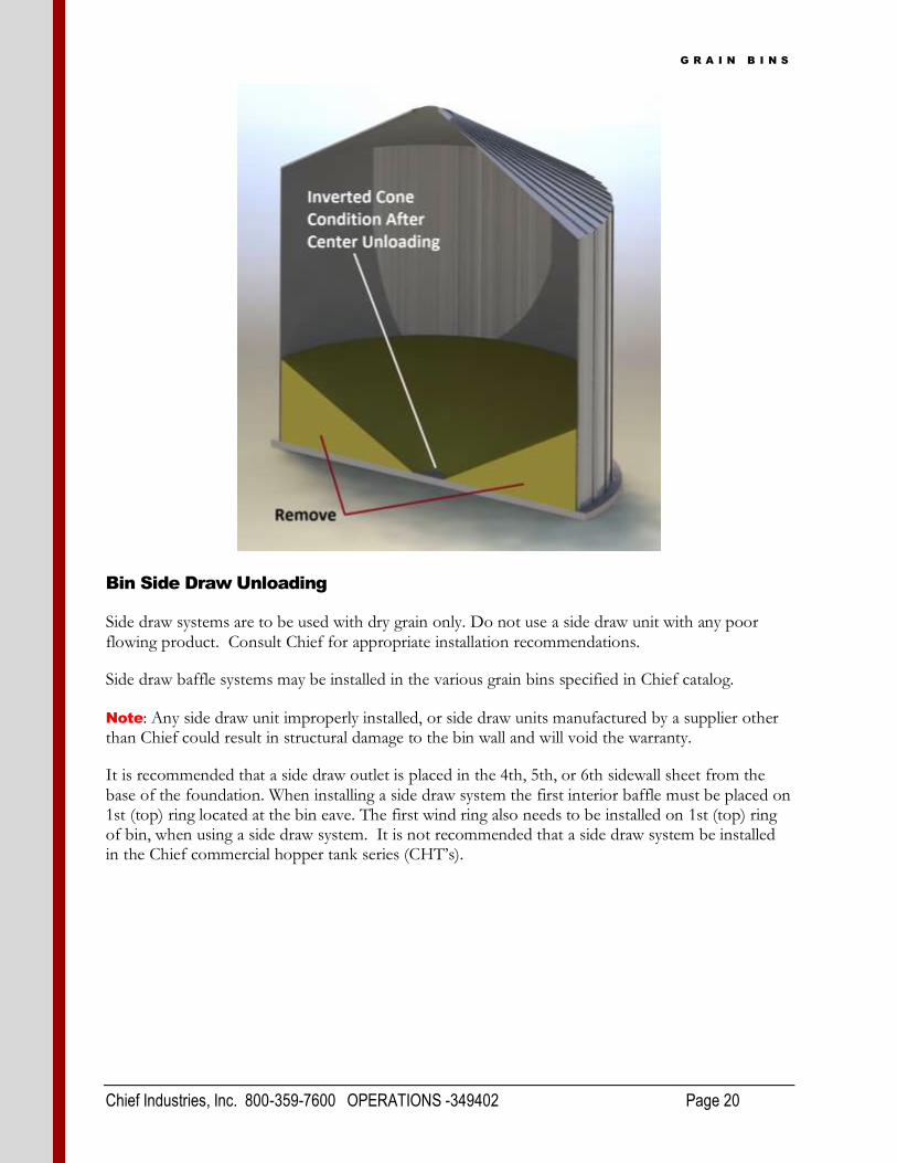
After unloading grain from the bin thru the center discharge, the remaining inverted cone of grain needs to be removed to prevent spoilage of the grain and degrading the protective zinc coating of
the sidewall sheets. Note: Running the aeration fans with the grain in this inverted cone condition will not maintain proper condition of the grain. The airflow from the fans will be discharged thru the lowest grain depth at the center of the bin and will not circulate air at the bin wall.
G R A I N B I N S
Chief Industries, Inc. 800-359-7600 OPERATIONS -349402 Page 20
Bin Side Draw Unloading
Side draw systems are to be used with dry grain only. Do not use a side draw unit with any poor flowing product. Consult Chief for appropriate installation recommendations.
Side draw baffle systems may be installed in the various grain bins specified in Chief catalog.
Note: Any side draw unit improperly installed, or side draw units manufactured by a supplier other than Chief could result in structural damage to the bin wall and will void the warranty.
It is recommended that a side draw outlet is placed in the 4th, 5th, or 6th sidewall sheet from the base of the foundation. When installing a side draw system the first interior baffle must be placed on 1st (top) ring located at the bin eave. The first wind ring also needs to be installed on 1st (top) ring of bin, when using a side draw system. It is not recommended that a side draw system be installed in the Chief commercial hopper tank series (CHT’s).

G R A I N B I N S
Chief Industries, Inc. 800-359-7600 OPERATIONS -349402 Page 21
After installing the side draw unit, the operating instruction labels must be installed in plain view at operator level at the control chain operating station. The label must be clearly visible to anyone operating the side draw. Installation of the side draw is not complete until these labels are in place.
Any downspout attached to the gate assembly or discharge spout must be supported by an independent means. The discharge spout and gate assembly are not intended to support downspout loads.
Note: Grain bins with side draw systems cannot be loaded at the peak and unloaded from the side draw simultaneously. If multiple side draw systems are installed on a grain bin, only one side draw can be used at a time. If 2 side draw systems are installed on the grain bin, they must be placed 180 degrees apart.

G R A I N B I N S
Chief Industries, Inc. 800-359-7600 OPERATIONS -349402 Page 22
After removing grain from the grain bin using the side draw system it is required that the grain is “cored” from the center discharge to level the grain in the bin before refilling. In addition, prior to prolonged storage, grain should be “cored” or taken to a level condition. “Coring” refers to removing grain from center discharge to create an inverted cone with the grain until the grain is level across the bin at the sidewall.
Note: Failure to follow the side draw operation instructions can cause structural damage and will void the warranty.

G R A I N B I N S
Chief Industries, Inc. 800-359-7600 OPERATIONS -349402 Page 23
Maintenance:
1. Base
a. Inspect base as often as possible for spoilage of grain. Spoilage of grain is a direct indication of excess moisture. If spoilage is present, thoroughly clean surface. If oxidation is present, remove oxidation and apply corrosion resistant paint. After paint has dried, apply base sealer to effected area.
2. Sidewall
a. Sidewall inspection must also be conducted at least annually. Should leaks occur or spoilage is present, thoroughly clean affected surfaces. If oxidation is present, remove oxidation and apply corrosion resistant paint. Finally apply caulk to area of concern.
b. Note: All anchor bolts must be retightened after the bin has been filled to capacity for the first time.
c. Note: Annual inspection of the sidewall structure should be made to verify bolts are tight and torque recommendation maintained, and that washer heads have maintained a proper seal. Re-tighten hardware as required.
3. Roof
a. Annual inspection of the roof structure should be made to verify there are no holes in the roof panels and all connections are water tight. If leaks should occur apply weatherproof caulk in the area of concern.
4. Doors
a. Inspect doors and manholes as often as possible to verify a proper seal is maintained.
5. Decals
a. Be sure all warning decals are installed in proper locations. Contact Chief for replacements of all damaged or unreadable warning decals.
Manual Revisions
2-13-2013
o Peak Loads
10-1-2015
o General formatting update
2-26-2016
o Sidewall Maintenance

G R A I N B I N S
Chief Industries, Inc. 800-359-7600 WARRANTY -349402 Page 24
STANDARD LIMITED WARRANTY
Chief Grain Bin Products
1. Definitions. The following terms, when they appear in the body of this Standard Limited Warranty for Grain Bin Products in initial capital letters shall have the meaning set forth below: A. Accepted Purchase Order shall mean the Purchase Order identified below. B. Chief shall mean Chief Agri/Industrial, a division of Chief Industries, Inc. C. Original Owner shall mean the original owner identified below. D. Product shall mean the Agri/Industrial Equipment as described in the Accepted Purchase
Order. E. Reseller shall mean the authorized Chief Agri/Industrial Equipment dealer identified below.
2. Limited Product Warranty. Upon and subject to the terms and conditions set forth below, Chief
hereby warrants to the Reseller, and, if different, the Original Owner as follows: A. All new Products delivered to the Reseller or the Original Owner by Chief pursuant to the
Accepted Purchase Order will, when delivered, conform to the specifications set forth in the Accepted Purchase Order;
B. All new Products delivered pursuant to the Accepted Purchase Order will, in normal use and service, be free from defects in materials or workmanship; and
C. Upon delivery, Chief will convey good and marketable title to the Products, free and clear of any liens or encumbrances except for, where applicable, a purchase money security interest in favor of Chief.
3. Duration of Warranty and Notice Requirements. Subject to the Exceptions, Exclusions
and Limitations set forth below, the warranties set forth in Section 2 above shall apply to all covered non-conforming conditions that are discovered within the first sixty (60) months following delivery of the Product to the carrier designated by the Reseller and/or the Original Owner at Chief’s manufacturing facility in Kearney, Nebraska (the “Warranty Period”) and are reported to the Chief as provided in Section 4 below within thirty (30) days following discovery (a “Notice Period”).
4. Notice Procedure. In order to make a valid warranty claim, the Reseller and/or the Original
Owner must provide Chief with a written notice of any nonconforming condition discovered during the Warranty Period within the applicable Notice Period specified in Section 3 above. Said notice must be in writing; be addressed to Chief Industries, Inc., Agri/Industrial Division, Customer Service Department, P.O. Box 848, Kearney, NE 68848; and contain the following information: (a) the Customer’s name and address; (b) the Reseller’s name and address; (c) the make and model of the Product in question; (d) the current location of the Product; (e) a brief description of the problem with respect to which warranty coverage is claimed; and (f) the date on which the Product was purchased.
5. Exceptions and Exclusions. Anything herein to the contrary notwithstanding, the warranties set
forth in Section 2 above do not cover any of the following, each of which are hereby expressly excluded: A. Defects that are not discovered during the applicable Warranty Period; B. Defects that are not reported to the Chief Agri/Industrial Division Customer Service
Department in conformity with the notice procedure set forth in Section 4 above within the applicable Notice Period specified in Section 3;
C. Any used or pre-owned Products; D. Any Chief manufactured parts that are not furnished as a part of the Accepted Purchase
Order; E. Any fixtures, equipment, materials, supplies, accessories, parts or components that have been
furnished by Chief but are manufactured by a third party; F. Any Products which have been removed from the location at which they were originally
installed; G. Any defect, loss, damage, cost or expense incurred by the Reseller or the Original Owner to
the extent the same arise out of, relate to or result, in whole or in part, from any one or more of the following:

G R A I N B I N S
Chief Industries, Inc. 800-359-7600 WARRANTY -349402 Page 25
(i) Usual and customary deterioration, wear or tear resulting from normal use, service and exposure;
(ii) Theft, vandalism, accident, war, insurrection, fire or other casualty; (iii) Any damage, shortages or missing parts which result during shipping or are otherwise
caused by the Reseller, the Original Owner and/or any third party; (iv) Exposure to marine environments, including frequent or sustained salt or fresh water
spray; (v) Exposure to corrosive, chemical, ash, smoke, fumes, or the like generated or released
either within or outside of the structure on which the Product is installed, regardless of whether or not such facilities are owned or operated by the Reseller, the Original Owner or an unrelated third party;
(vi) Exposure to or contact with animals, animal waste and/or decomposition; (vii) The effect or influence the Product may have on surrounding structures, including,
without limitation, any loss, damage or expense caused by drifting snow; (viii) Any Product or portion thereof that has been altered, modified or repaired by the
Reseller, the Original Owner or any third party without Chief’s prior written consent; (ix) Any Product or portion thereof that has been attached to any adjacent structure without
Chief’s prior written approval; (x) Any Product to which any fixtures, equipment, accessories, materials, parts or
components which were not provided as a part of the original Accepted Purchase Order have been attached without Chief’s prior written approval;
(xi) The failure on the part of the Reseller, the Original Owner or its or their third party contractors to satisfy the requirements of all applicable statutes, laws, ordinances rules, regulations and codes, (including zoning laws and/or building codes);
(xii) The use of the Product for any purpose other than the purpose for which it was designed; and/or
(xiii) The failure of the Reseller, the Original Owner and/or any third party to: (a) properly handle, transport and/or store the Product or any component part
thereof; (b) properly select and prepare a site that is adequate for the installation and/or
operation of the Product or any component part thereof; (c) properly design and construct a foundation that is adequate for the installation
and/or operation of the Product or any component part thereof; (d) properly set up, erect, construct or install the Product and/or any component part
thereof; and/or (e) properly operate, use, service and/or maintain the Product and each component
part thereof. 6. Resolution of Warranty Claims. In the event any nonconforming condition is discovered within
the Warranty Period and Chief is notified of a warranty claim as required by Section 4 prior to the end of the applicable Notice Period set forth in Section 3 above, Chief shall, with the full cooperation of the Reseller and the Original Owner, immediately undertake an investigation of such claim. To the extent Chief shall determine, in its reasonable discretion, that the warranty claim is covered by the foregoing Limited Product Warranty, the following shall apply: A. Warranty Claims With Respect to Covered Non-Conforming Conditions Discovered Within the
First Three Hundred Sixty Five (365) Days and Reported to Chief Within Thirty (30) Days of Discovery. In the case of a warranty claim which relates to a covered non-conforming condition that is discovered during the first three hundred sixty five (365) days of the Warranty Period and is reported to Chief as required by Section 4 within thirty (30) days of discovery as required by Section 3, Chief will, as Chief’s sole and exclusive obligation to the Reseller and the Original Owner, and as their sole and exclusive remedy, work in cooperation with the Reseller and the Original Owner to correct such non-conforming condition, and in connection therewith, Chief will ship any required replacement parts to the “ship to address” set forth in the Accepted Purchase Order FOB Chief’s facilities in Kearney, Nebraska, and will either provide the labor or reimburse the Reseller or the Original Owner, as may be appropriate in the circumstances, for any out of pocket expense the Original Owner may reasonably and necessarily incur for the labor that is required to correct such non-conforming condition, provided that if work is to be performed by the Reseller or a third party contractor, Chief may require at least two competitive bids to perform the labor required to repair or correct the defect and reserves the right to reject all bids and obtain additional bids. Upon acceptance of a bid by Chief, Chief will authorize the necessary repairs.

G R A I N B I N S
Chief Industries, Inc. 800-359-7600 WARRANTY -349402 Page 26
B. All Other Warranty Claims. Except as is otherwise provided in subsection 6A above, in the case of all other warranty claims which relate to covered non-conforming conditions that are discovered during the Warranty Period and are reported to Chief as required by Section 4 within thirty (30) days following discovery, Chief will, as Chief’s sole and exclusive obligation to the Reseller and the Original Owner, and as the Reseller’s and the Original Owner’s sole and exclusive remedy, ship any required replacement parts to the Original Owner at the “ship to address” specified in the Accepted Purchase Order FOB Chief’s facilities in Kearney, Nebraska; and in such event, Chief shall have no responsibility or liability to either the Reseller or the Original Owner for the cost of any labor required to repair or correct the defect.
7. Warranty Not Transferable. This Warranty applies only to the Reseller and the Original Owner
and is not transferable. As such, this Warranty does not cover any Product that is sold or otherwise transferred to any third party following its delivery to the Original Owner.
8. Limitation on Warranties, Liabilities and Damages. The Reseller and the Original Owner expressly agree that the allocation of the risk, liability, loss, damage, cost and expense arising from any Product that does not conform to the limited warranty given in Section 2 above are fair and reasonable and acknowledge that such allocation was expressly negotiated by the parties and was reflected in the Purchase Price of the Product. Accordingly the Reseller and the Original Owner expressly agree as follows: A. Disclaimer of Implied Warranties. EXCEPT AS IS OTHERWISE EXPRESSLY SET FORTH
HEREIN, CHIEF MAKES NO OTHER REPRESENTATIONS OR WARRANTIES OF ANY KIND WHATSOEVER, WHETHER EXPRESS OR IMPLIED, BY OPERATION OF LAW, COURSE OF DEALING OR OTHERWISE WITH RESPECT TO THE PRODUCT, ANY COMPONENT PART THEREOF OR ANY OTHER GOODS OR SERVICES THAT CHIEF MANUFACTURES, FABRICATES, PRODUCES, SELLS OR PROVIDES TO THE DEALER OR THE ORIGINAL OWNER PURSUANT TO THE TERMS OF ANY ACCEPTED PURCHASE ORDER, INCLUDING WITHOUT LIMITATION ANY REPRESENTATION OR WARRANTY WITH RESPECT TO DESIGN, CONDITION, MERCHANTABILITY OR FITNESS OF THE PRODUCT OR ANY OTHER GOODS OR SERVICES FOR ANY PARTICULAR PURPOSE OR USE.
B. Limitation on Liability. EXCEPT AS IS OTHERWISE EXPRESSLY SET FORTH IN SECTION 6 ABOVE, CHIEF'S LIABILITY TO THE DEALER AND/OR THE ORIGINAL OWNER WITH RESPECT TO ANY DEFECTS IN ANY PRODUCTS OR FOR ANY OTHER GOODS OR SERVICES WHICH DO NOT CONFORM TO THE WARRANTIES SET FORTH ABOVE SHALL NOT, IN ANY EVENT, EXCEED THE ACTUAL COST OF SUCH NON-CONFORMING PRODUCT, GOODS OR SERVICES AS DETERMINED PURSUANT TO THE ACCEPTED PURCHASE ORDER; AND
C. Limitation on the Nature of Damages. EXCEPT AS EXPRESSLY PROVIDED IN SECTION 6 ABOVE, CHIEF SHALL NOT, UNDER ANY CIRCUMSTANCES, BE LIABLE TO THE DEALER, THE ORIGINAL OWNER OR ANY THIRD PARTY FOR ATTORNEY FEES COURT COSTS OR ANY OTHER SPECIAL, INDIRECT, INCIDENTAL, CONSEQUENTIAL, LIQUIDATED OR PUNITIVE DAMAGES OF ANY NAME, NATURE OR DESCRIPTION AS A RESULT OF THE FAILURE OF ANY PRODUCT OR ANY OTHER GOODS OR SERVICES PURCHASED BY THE DEALER OR THE ORIGINAL OWNER FROM CHIEF PURSUANT TO THE ACCEPTED PURCHASE ORDER TO CONFORM TO THE LIMITED WARRANTIES SET FORTH IN SECTION 2 ABOVE.
8. Applicable Law. This Limited Product Warranty has been issued, accepted and entered into by
the Reseller, the Original Owner and Chief in the State of Nebraska and shall be governed by, and construed in accordance with, the internal laws of the State of Nebraska. Any legal action or proceeding with respect to any goods or services furnished to the Original Owner by Chief in connection herewith, or any document related hereto shall be brought only in the district courts of Nebraska, or the United States District Court for the District of Nebraska, and, by execution and delivery of this Limited Product Warranty, the undersigned Original Owner hereby accept for themselves and with respect to their property, generally and unconditionally, the jurisdiction of the aforesaid courts. Further, the undersigned Original Owner hereby irrevocably waives any objection, including, without limitation, any forum non conveniens, which it may now or hereafter have to the bringing of such action or proceeding in such respective jurisdictions.
ACKNOWLEDGMENT OF RECEIPT

G R A I N B I N S
Chief Industries, Inc. 800-359-7600 WARRANTY -349402 Page 27
By its signature hereto, the undersigned Reseller represents and warrants to Chief that the Reseller has provided a true, correct and complete copy of this Standard Limited Warranty to the Original Owner at the time the product was purchased. Reseller Name and Address: _______________________________ _______________________________ _______________________________ Original Owner Name and Address: _______________________________ _______________________________ _______________________________ Accepted Purchase Order No. _________________________ Original Jobsite Address: _____________________________________ _____________________________________ _____________________________________ RESELLER: By: _________________________________ Date Print name and title
4843-5948-9057, v. 1

G R A I N B I N S
Chief Industries, Inc. 800-359-7600 MANUAL - 349402 Page 28
Should you have any questions concerning assembly instructions, parts or drawings, please feel free to contact us at any of the following.
Chief Industries, Inc. Inc. 4400 East 39th Street • PO Box 848
Kearney, NE 68847 Phone 800.359.7600
For more information about Chief Industries, Inc. and additional products or services visit our website www.agri.Chiefind.com