grain drying - installation manual for …...grain level, the more efficient the drying process will...
TRANSCRIPT

Shivvers Manufacturing, Inc.614 W. English St.Corydon, IA 50060
Ph. (641) 872-1005 ** Fax (641) 872-1593www.shivvers.com
SHIVVERS
P-121199/21/2015
INSTALLATION MANUALfor
SHIVVERS HIGH TORQUE DRIVE SYSTEM


TABLE OF CONTENTS
SECTION Attention Warranty Introduction Safety Location of Safety Decals Important Site Preparation Bin Layout Installing Horizontal Unloader and Gear Basket Installing Dual Motor Drive Installing Flooring Installing Tapered Sweeps and Track Installing Center Vertical
PAGE 1 1 2 2-4 4 5 6 7-11 12-21 22-28 29 30-32 33-37

ATTENTION
The Shivvers Circu-Lator will set up flow patterns of grain which exert extra stress on the walls and floor of the drying bin. Additional floor supports are normally required for the drying floor. Bin sidewall stiffeners are often required. Consult bin and floor manufacturers for their recommendations before installing and using Shivvers Circu-Lator. Shivvers will not be responsible for structural failure of the drying floor or bin, or for any loss, damage, or injury relating to use of the Circu-Lator. Large amounts of water are removed during the drying process. A way to remove this water from inside the drying bin is required. This is usally accomplished by installing roof vents. We strongly recommend having the bin roof raised about 3/4" above the bin side wall. This is especially important while drying when outside temperatures are below freezing. Having the roof raised will keep a lot of the condensation from running down the inside of the bin wall.
WARRANTY
PRO RATEDTWO SEASON WARRANTY
Shivvers Circu-Lator is guaranteed for the first season of harvest operation, regardless of purchase date, provided it is installed and operated as directed by instructions and manuals. Under this warranty, SHIVVERS will repair or replace such parts that are returned to us, freight prepaid, and found to be defective by the factory. During the second season of harvest operation, SHIVVERS will repair or replace at 50% of retail price, such parts that are returned to us freight prepaid and found defective by the factory. Vee-Belts are not covered by this warranty. Electric motors (including spreader motors) are covered under warranty by the motormanufacturers and are not covered by the SHIVVERS warranty. SHIVVERS makes no warranty of any kind, expressed or implied, except as stated herein and buyer assumes all risk and liability resulting from the use of products manufactured by SHIVVERS, whether used singly or in combination with other products. For purposes of this warranty, "Season of Harvest" is defined as the period of time between June 1st and December 31st of a calender year.
1
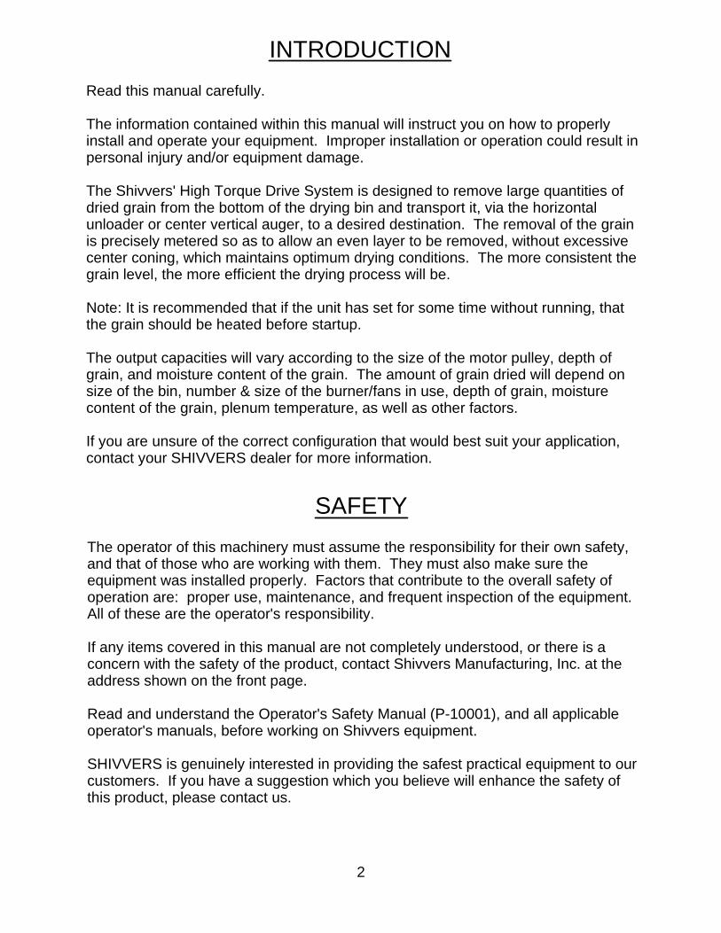
INTRODUCTIONRead this manual carefully. The information contained within this manual will instruct you on how to properly install and operate your equipment. Improper installation or operation could result inpersonal injury and/or equipment damage. The Shivvers' High Torque Drive System is designed to remove large quantities of dried grain from the bottom of the drying bin and transport it, via the horizontal unloader or center vertical auger, to a desired destination. The removal of the grain is precisely metered so as to allow an even layer to be removed, without excessive center coning, which maintains optimum drying conditions. The more consistent thegrain level, the more efficient the drying process will be. Note: It is recommended that if the unit has set for some time without running, that the grain should be heated before startup. The output capacities will vary according to the size of the motor pulley, depth of grain, and moisture content of the grain. The amount of grain dried will depend on size of the bin, number & size of the burner/fans in use, depth of grain, moisture content of the grain, plenum temperature, as well as other factors. If you are unsure of the correct configuration that would best suit your application, contact your SHIVVERS dealer for more information.
SAFETYThe operator of this machinery must assume the responsibility for their own safety, and that of those who are working with them. They must also make sure the equipment was installed properly. Factors that contribute to the overall safety of operation are: proper use, maintenance, and frequent inspection of the equipment.All of these are the operator's responsibility. If any items covered in this manual are not completely understood, or there is a concern with the safety of the product, contact Shivvers Manufacturing, Inc. at the address shown on the front page. Read and understand the Operator's Safety Manual (P-10001), and all applicable operator's manuals, before working on Shivvers equipment. SHIVVERS is genuinely interested in providing the safest practical equipment to ourcustomers. If you have a suggestion which you believe will enhance the safety of this product, please contact us.
2

SAFETY (cont'd)
TAKE NOTE ANYTIME THIS SAFETY ALERT SYMBOL APPEARS. YOUR SAFETY, AND THAT OF THE PERSONS AROUND YOU IS AT STAKE.
The safety alert symbol will be accompanied by one of three signal words whose definitions are given as: DANGER: Red and white. Indicates an imminently hazardous situation that, if not avoided, will result in death or serious injury. This signal word is to be limited to the most extreme situations, typically for machine components that, for functional purposes, cannot be guarded. WARNING: Orange and black. Indicates a potentially hazardous situation that, if not avoided, could result in death or serious injury, and includes hazards that are exposed when guards are removed. It may also be used to alert against unsafe practices. CAUTION: Yellow and black. Indicates a potentially hazardous situation that, if not avoided, may result in minor or moderate injury. It may also be used to alert against unsafe practices. Besides these, you will find: IMPORTANT: Black on white. This is not a safety decal. It is for important details pertaining to the maintenance, operation, or setup of the equipment to keep it running smoothly and/or efficiently. Anytime you are working with your drying unit, be sure to observe these common sense rules: 1.) All units must be equipped with the main power disconnect switch. This disconnect switch must shut power off to the complete drying system. It must have the capability of being locked into the OFF or OUT position. Disconnect and LOCK OUT this main power disconnect switch before conducting any inspection, maintenance, repair, adjustment, or cleaning of the drying system. When you must have the electrical power on to troubleshoot equipment, do it from a safe distance, and always from outside the bin. 2.) Keep the bin entrances locked at all times. To unlock the bin, first lower the Level-Dry (if so equipped), then shut the main power disconnect off. Take the safetylock off the bin entrance and place it on the main power disconnect before opening the bin entrance. Never enter the drying bin unless the Level-Dry (if so equipped), iscompletely lowered, and all power is disconnected and locked out.
3

3.) Always keep all shields and guards in place. If shields or guards must be removed for inspection or maintenance, replace them before unlocking and turning power back on. 4.) Be sure everyone is clear of all the drying and transferring equipment, and outside of all bins before unlocking and turning power on. Some equipment may runupon re-application of power. 5.) Make sure that all decals are in place and are easy to read. Do not operate the equipment with missing or illegible decals. If replacements are needed, contact Shivvers Manufacturing, Inc. or your dealer. 6.) Prior to use, inspect all equipment to insure that it is in good operating condition.Do not operate with missing, damaged, or worn parts. Use only SHIVVERS approved replacement parts. 7.) Metal edges can be sharp. Wear protective clothing and handle equipment and parts with care. 8.) Keep children and bystanders away from drying and transferring equipment at alltimes. 9.) If going up the bin ladder and/or performing maintenance on the top of the bin, take precautions to prevent accidental falls. When on top of the bin, wear a safety harness or other safety device. 10.) At least annually, review all operating and safety manuals with any personnel working with this equipment. Always train new employees before they operate the drying equipment. Insist that they read and understand the operating and safety manuals.
SAFETY (cont'd)
LOCATION OF SAFETY DECALSFor complete instructions as to where to find safety decals and where to place field installed safety decals, consult your Operator's Safety Manual (P-10001).
4

IMPORTANTFloor Supports: Floor LayoutSHIVVERS Floor and Floor Supports for Circu-Lator use are warranted for use with SHIVVERS circulating equipment. (If other brands are used, SHIVVERS will not be responsible for the drying floor or support system should it happen to fail). Bin Stiffeners:Bin stiffeners are required. Follow bin manufacturer's specific recommendations or use SHIVVERS Stiffeners. NOTE: Some bin manufacturers warrant heavy duty binsfor recirculation devices, but these are not warranted by SHIVVERS. Doors:Remove the Withdrawal Auger Cover Plate which is usually fastened to one of the door panels and extends into the bin. This and any other internal protrusion of substantial size (extra bulky ladders, etc.) should be removed as they would be pulled down by the flowing grain during Circu-Lator operation. All Doors must be of sound construction, and all original equipment door braces must be bolted in place during Circu-Lator operation.
5

SUPPORT POST INSTALLATION
SITE PREPARATION
Are you installing a large grain spreader? You may want to consider mounting it: 1.) During bin construction while the roof is near to the ground. 2.) Before the Center Vertical Auger and its supporting chains are installed, since these are very much in the way.
Follow the bin manufacturer's specific recommendations for a re-circulating bin.
Exit point of HTDA Unloader must be at least 24" away
from entrance door.
6

BIN LAYOUT
On new installations, mark where the centerline between the bins crosses the outer edge of the dryer bin foundation. Line up the centerline of a roof panel to the mark on the foundation, using a plumb bob if necessary. When a storage bin is being added to an existing drying bin installation, the centerline can be determined by tying a string to the center of the roof panel near the opening at the top of the bin, then stretching it outwardly from the bin and in alignment with the center of the roof panel, as shown. In most cases, the position ofthe storage bin can be adjusted to line up with the center of the roof panel.
7

BIN LAYOUTThe concrete pad for the drying bin should be as close to flat and level as possible. Make sure it is thick enough and has enough reinforcement so it will not crack and move. Consult the bin manufacturer for more information. A good, solid, flat and level foundation is required for the Circu-Lator to work properly. See fan and burner installation manuals for instructions on concrete pads for them. See suggested layouts in this manual for orientation of fans, horizontal unloader, and control boxes. The suggested layouts show pad sizes for SHIVVERS Blue Flame dryers. They also show a Compudry Command Center for the control box. Your installation may have something different, but the orientation should be similar.Try to align the bin sheets so the fan/burner entrance collar(s) do not have to be cut through a seam. The Horizontal Unloader must come out near the main entrance door of the bin. The control box must be within line of sight of the bin's main entrance door. There must be a main electrical disconnect switch. This switch must shut off all electrical power to the drying system. It must have the capability of being locked in the OFF position. It must be located near the bin's main entrance and within line of sight of the control box. A lockable disconnect switch for each Machine (Circu-Lator) motor is required near the bin entrance. These disconnect switches are NOT supplied by SHIVVERS, but can be obtained locally. Since the SHIVVERS drying system can operate at temperatures up to 200~F, all sealants in the plenum area must be able to withstand this temperature. Ordinary plastic roofing cement or tar will soften and should not be used. Possible materials to use are: 1.) Black Jack #1010, Neoprene Flashing Cement, by Gibson-Homans2.) Regular 100% Silicone Caulking3.) Stretch-a-Seal (TM), Bin and Elevator Sealant, by Farm Products Direct (Follow manufacturer's instructions) Ph (800) 669-93144.) Rubberflex Binseal Ph (800-817-2986) www.binseal.com All air leaks in the bin must be sealed off. The sealant should be applied from the inside of the plenum area, if at all possible. If it is applied from the outside, plenum pressure will probably blow it out.
8

BIN LAYOUT (cont'd)
FANLYT-1.DWG
HORIZONTALUNLOADER ENTRANCE
BIN
DOORCLEANOUT
TYPICAL
& TRANSITION
FORBLUE FLAME
VIEW OF ENTRANCE)
TURBO BOOSTERFOR
(WITH AN UNOBSTRUCTEDMAIN DISCONNECTCOMMAND CENTER/
COMPUDRY
8"
MACHINE MOTOR
DISCONNECT SWITCH
(one for each motor)
Shivvers Circulator 1-Fan Layout
BIN DIA.
3'
8'
2'
9
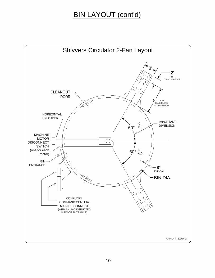
BIN LAYOUT (cont'd)
FANLYT-2.DWG
+10
-0+10
DIMENSIONIMPORTANT
HORIZONTALUNLOADER
DOORCLEANOUT
TYPICAL
& TRANSITION
FORBLUE FLAME
VIEW OF ENTRANCE)
TURBO BOOSTERFOR
(WITH AN UNOBSTRUCTEDMAIN DISCONNECTCOMMAND CENTER/
COMPUDRY
8"
-0
MACHINE MOTOR
DISCONNECT SWITCH
(one for each motor)
BIN ENTRANCE
Shivvers Circulator 2-Fan Layout
60°
60°
3'2'
8'
BIN DIA.
10

BIN LAYOUT (cont'd)
FANLYT-3.DWG
BIN ENTRANCE
MACHINE MOTOR
DISCONNECT SWITCH
(one for each motor)
-0+10
-0+10
HORIZONTALUNLOADER
DOORCLEANOUT
TYPICAL
& TRANSITION
FORBLUE FLAME
VIEW OF ENTRANCE)
TURBO BOOSTERFOR
(WITH AN UNOBSTRUCTEDMAIN DISCONNECTCOMMAND CENTER/
COMPUDRY
8"
Shivvers Circulator 3-Fan Layout
BIN DIA.
60°
60°
3'2'
8'
11

Step 1: For installations in existing bins, it is recommended that the floor be removed. If the old floor is going back in, number the individual floor pieces for convenience of re-installation. The entire concrete bin floor should be cleaned. Step 2: Determine the location where the horizontal unload tube will project through the bin sidewall. It should be within sight of the bin entrance and the dryer controller. At this location, measure down 8-1/2" from where the top of the floor will be. This will be the center of the horizontal unload tube. Hold the faceplate against the bin wall, with the control rod hole on top, and mark all holes on the bin wall. Cut a keyhole shape in the bin wall for the unload tube and control rod. Hanger bearing unloaders will require a larger hole. Make sure the faceplate will cover the hole that is cut.
INSTALLING HORIZONTAL UNLOADER ANDGEAR BASKET
8-1/2"
Top of Floor
ConcreteBin Floor
Hole forHorizontalUnload Tube
Faceplate
12

INSTALLING HORIZONTAL UNLOADER ANDGEAR BASKET (cont'd)
Step 3: Rough Locate HTDA. Place a folded towel across the bottom edge of the opening in the bin wall to protect theHTDA during installation. Be careful not to drop the unit at any time to avoid denting thetube. Put the open end of the HTDA through the bin wall and set it on the floor near theGBA. Outside the bin, assemble and install the Mounting Stand onto the HTDA. This should be clamped onto the tube 5" away from the bin wall, leaving room for the 2-piece Face Plate to be installed later. This stand is to support the HTDA during installation, leveling,as well as for the life of the machine.
Step 4: Assemble and install a second mounting stand onto the HTDA. This should be clamped to the tube at about halfway between the GBA and the bin wall. Make surethe location will not interfere with any intermediate wells. This stand is to support the HTDA during installation, leveling, as well as for the life of the machine.
MountingStand
HTDA(High Torque
Drive Assembly)
GBA(Gearbox Basket
Assembly)
F-1011-07 (4)Nut, 3/4-10
226-005W8" Stand Wldt.
226-011P (2)8" Halfband, Stand
Mounting Stand
HTDA(High Torque
Drive Assembly)
GBA(Gearbox BasketAssembly)
Transition dischargemust be to the right
13

2-15/16"
7-1/8"
5"
3/8"
1/8" - 1/4" Gap Required
656-023P (3)Housing Shims
HTDA
GBA
ChainCouplers
Drive Shaft Exposure
Flite Tube Exposure
INSTALLING HORIZONTAL UNLOADER ANDGEAR BASKET (cont'd)
Step 5: Prepare gearbox and basket for installation Check the gearbox to insure it is lubricated. Remove the shipping wire that holds the top gearbox to the bottom gearbox. Screw jam nuts, from 222-085A Basket Hardware Sack, on the 3/4" X 12" support legs approximately 9". Screw the support legs, with the jam nuts, into the basket until the top of the basket will be about the same height as the drying bin floor. Remove the Chain Coupler Guard and keep it for later re-installation. Step 6: Join HTDA to the GBA Positioning of the HTDA housing is critical to prevent binding and misalignment. Pre-assembly is necessary to determine the number of housing shims required. Fasten the HTDA to the GBA using all the shims but only four bolts and tighten snugly. The HTDA should now be supported by the mounting stand outside the bin and the GBA at the center of the bin. Outside the bin, measure the flite tube exposed from the front of the HTDA Transition, this should be: 7-1/8" ±1/32". If not, loosen set screws of the bearing, adjust as needed, and re-tighten setscrews. Measure the drive shaft exposed from the flite tube, this should be: 2-15/16" ±1/32". If not, pull or push gently to adjust.
95-020PChain CouplerGuard
F-1011-07Nut, Hex3/4-10 NC
222-037WLeg, Basket
Weldment
Approx. 4-1/2"
Height ofFloor
14

INSTALLING HORIZONTAL UNLOADER ANDGEAR BASKET (cont'd)
Step 6: Join HTDA to the GBA (cont'd) Inside the bin, measure the space between the chain couplers (this should be: 3/8" ±1/32"). If not, determine the number of shims to be removed (approximately 1 shim foreach 1/8"). Using all six bolts, re-attach the HTDA Housing to the GBA and tighten snugly. Remeasure the exposed drive shaft and chain coupler distance. Adjust until drive shaftis exposed 2-15/16" and chain coupler distance is 3/8". Important: There must also be a 1/8-1/4" gap between the flite tube and the chain coupler sprocket to avoid undue friction during operation, which could start a bin fire. The units are shipped with an "O" ring to help maintain this spacing during installation. It is not necessary that it remains in place, but it is also OK to leave it there.
15

INSTALLING HORIZONTAL UNLOADER ANDGEAR BASKET (cont'd)
Step 7: Using the 656-017A hardware sack, connect the drive shaft of the horizontal unloader to the gearbox input shaft.
Slide pins of master link through chain farthest from gearbox with chain closest to gearbox folded back. Insert 2 connecting plates betweenchains, while sliding in master link pins.
Fold inside chain back onto sprocket and completely insert master link pins.
Install spring clip onto master link pins with solid end (not split end) facing toward sprocket rotation. Make sure spring clip is securely seated into master link pin grooves.
Place another connecting plate on master link pins.
3/8"space
betweensprocket
faces
Rotation
RotationD-3226Chain, 15 Link
with Master Link#50 Double Roller
ConnectingPlate
Split End
SpringClip
MasterLink #50DoubleRoller
Connecting Plates
16

INSTALLING HORIZONTAL UNLOADER ANDGEAR BASKET (cont'd)
Step 8: Setup of HTDA/GBA Joined Unit Re-measure to confirm that the square shaft on top of the gearbox is centered in thebin. Adjust as needed. This centering should be checked at least every 90 degrees around the bin. Level the Gearbox Basket Assembly (GBA):Adjust the support legs of the GBA until the top of it is level and all four support legs are in contact with the slab. Weight must be carried by all four support legs of the GBA. This would be a good time to check that the gearbox is square to the floor using the 423-351-001A Gearbox Laser Mount Kit. Level the HTDA Transition:The top of the HTDA transition should be level. If not, loosen the HTDA housing from the front of the GBA and loosen the top clamp of the mouting stands. Rotate the HTDA until the front of the transition is level. Re-tighten the bolts that fasten the HTDA to the GBA. Level the HTDA Horizontal Unload Auger:Adjust the outside and inside mounting stand height as needed, then make sure the 5" space has been maintained on the outside stand and tighten both stands securely.
GBA
HTDAHorizontal
Unload Auger
HTDATransition
5"
Gearbox LaserMount Kit
Locking Nut(2 per side)
Locking Nut(each side)
17

INSTALLING HORIZONTAL UNLOADER ANDGEAR BASKET (cont'd)
Step 9: Assemble the lower face plate weldment and half band onto the HTDA between the mounting stand and the bin wall with minimal clamping force. Using two bolts, fasten the upper face plate to the lower face plate weldment and slide it up against the bin wall, leveling as needed. Using the face plate as a template, drill all bolt holes in the bin wall. Using a marker, draw around the faceplate to show where thumb-seal will be needed. Remove the face plate and apply a generous bead of thumb-seal just inside the face plate mark on the bin wall. Re-install the face plate assembly, making sure it is completely sealed against the bin wall. Once GBA, HTDA, and the horizontal transition are level, be sure to tighten the face plate into position. Step 10: Re-install the Chain Coupler Guard removed earlier.
LowerFace Plate
UpperFace Plate
Thumbseal-use generously-sandwich in so it oozesout during tightening
F-1239 (14)Locknut, 3/8-16with Nyloc
F-1009-03 (14)Washer, Flat, 3/8"
F-1307 (10)3/8-16 X 1-1/4Capscrew
F-1015-28 (4)3/8-16 X 1-3/4Capscrew
E-63721-3/8" Metal Plug
656-049PControl Rod
Bushing
201B-024P8" Halfband
Clamp
F-1009-03 (Ref.)F-1239 (Ref.)
95-020PChain Coupler Guard
18
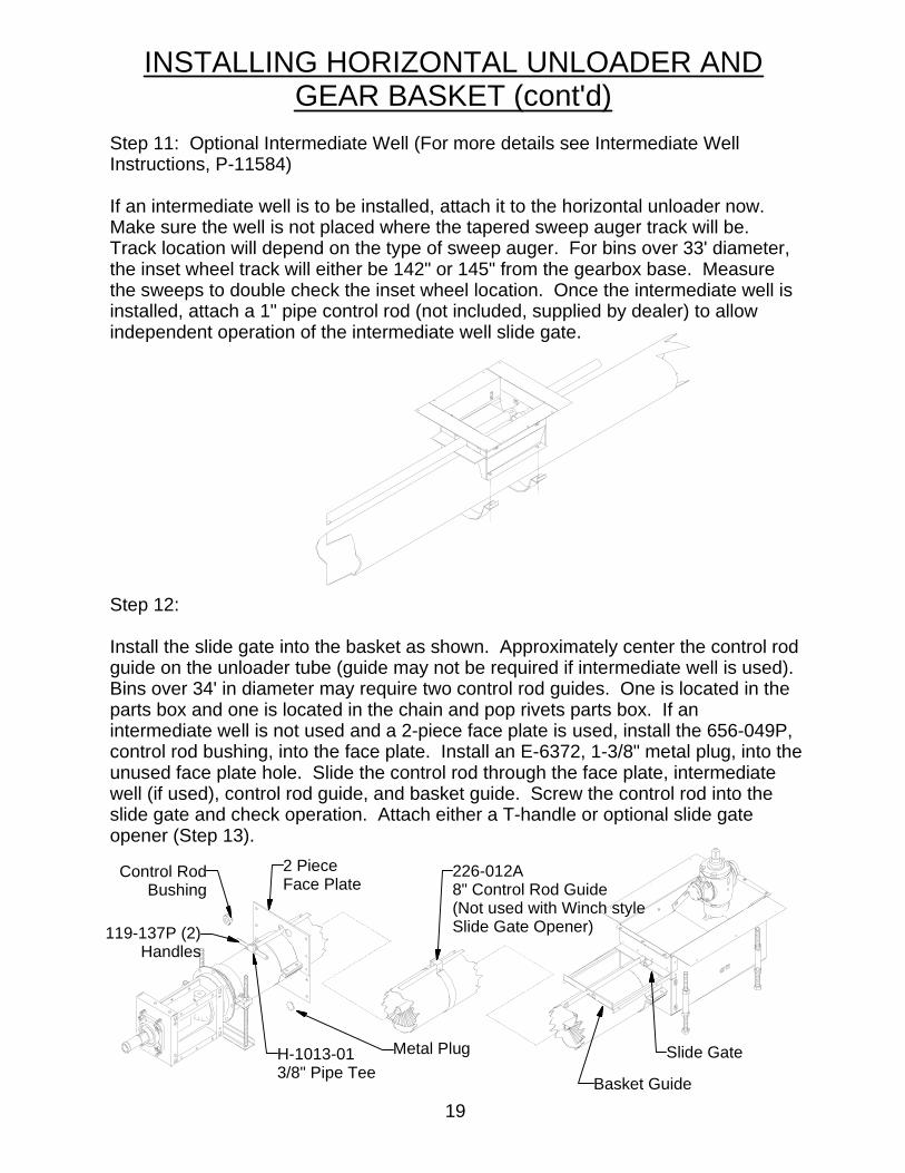
INSTALLING HORIZONTAL UNLOADER ANDGEAR BASKET (cont'd)
Step 11: Optional Intermediate Well (For more details see Intermediate Well Instructions, P-11584) If an intermediate well is to be installed, attach it to the horizontal unloader now. Make sure the well is not placed where the tapered sweep auger track will be. Track location will depend on the type of sweep auger. For bins over 33' diameter, the inset wheel track will either be 142" or 145" from the gearbox base. Measure the sweeps to double check the inset wheel location. Once the intermediate well is installed, attach a 1" pipe control rod (not included, supplied by dealer) to allow independent operation of the intermediate well slide gate. Step 12: Install the slide gate into the basket as shown. Approximately center the control rod guide on the unloader tube (guide may not be required if intermediate well is used). Bins over 34' in diameter may require two control rod guides. One is located in the parts box and one is located in the chain and pop rivets parts box. If an intermediate well is not used and a 2-piece face plate is used, install the 656-049P, control rod bushing, into the face plate. Install an E-6372, 1-3/8" metal plug, into theunused face plate hole. Slide the control rod through the face plate, intermediate well (if used), control rod guide, and basket guide. Screw the control rod into the slide gate and check operation. Attach either a T-handle or optional slide gate opener (Step 13).
Control RodBushing
2 PieceFace Plate
H-1013-013/8" Pipe Tee
Metal Plug
119-137P (2)Handles
226-012A8" Control Rod Guide(Not used with Winch styleSlide Gate Opener)
Basket Guide
Slide Gate
19

INSTALLING HORIZONTAL UNLOADER ANDGEAR BASKET (cont'd)
Step 13: Optional Slide Gate Opener (91B-001A for 8" - See P-8401 for more details.) Slide level rack over control rod and screw pipe cap on end of control rod. With the lever rack against the pipe cap, drill a 5/16" diameter hole through the control rod at the hole in the lever rack. Install the roll pin through both parts. With the slide gate closed, center the lever pivot with the center of the first hole in the lever rack and clamp halfbands securely. Slide the pivot pin through the lever pivot and lever and install cotter pins on each side.
20
Pipe Cap
Cotter Pin
Pivot Pin
Control RodBushing
Roll Pin
Lever Rack
Control Rod
91C001A (8") AND 91D-001A (6")Winch Style Slide Gate Opener (See P-13189 for Installation Instructions.)

INSTALLING HORIZONTAL UNLOADER ANDGEAR BASKET (cont'd)
Step 14: Install conduit for gearbox Hi-Limit. The gearbox Hi-limit will shut off the drying fan(s) if it gets above 240° F. What the gearbox Hi-limit will wire to depends on the type of control and how many fans are used in the installation. If a Compudry Command Center is used, the gearbox Hi-Limit will always wire to it. If 2 or more fans are used, the gearbox Hi-limit will wire to either the dryer control box or a Grain Hi-limit Control box. Only if a control other than a Compudry Command Center is used, and there is only one fan on the bin, will the gearbox Hi-limit go directly to the fan. The important thing is to get the conduit installed before the bin floor is in place. The wire can always be routed wherever it needs to go once it is on the outside of the bin. If the conduit is not going to be in-line with the horizontal unloader, it may be better to wait until the floor supports and rails are in place to route the conduit so it doesn't interfere with floor support placement. Use the high temperature wire (641-046A) supplied for under the floor. Once outside the bin, any appropriate electrical control wire can be used. Pull 2 of the high temperature wires through the conduit. Connect each wire to a gearbox Hi-limit wire in the junction box on the back of the basket. Use regular wire nuts to make the connection. Refer to installation manual for dryer control used on where to connect the other end of the gearbox Hi-limit wires.
ConcreteBin Floor
To CommandCenter or other control
Bin Wall
HorizontalUnloader
ConduitGearbox
Basket
GearboxHi-Limit
Junction Box
Conduit underBasket andHorizontalUnloader
Possible gearbox Hi-Limit conduit routing, or else wait until floor supports and rails are in place, but before floor planks are installed.
21

Step 1: Remove all contents from shipping box. Use hardware, as shown, from sack (654-330A) to secure the Front Frame Bracket (654-325P) to the 8" horizontal unloader transition. DO NOT tighten bolts completely at this time.
INSTALLING DUAL MOTOR DRIVE
Step 2: Use hardware, as shown, from sack (654-330A) to position the Rear Frame Bracket (654-324P) to the horizontal unloader transition. Do not tighten 1/2" bolt into transition. Place the Idler Bushing (654-314P) into hole in the Front Frame Bracket (654-325P). Secure with hardware, as shown, from sack (654-330A).
1/4-20 x 1" Capscrew
1/4" LockWasher
Idler Bushing
Front Frame Bracket
Rear Frame Bracket
3/8" Flat Washer
3/8-16 x 1-1/4" Capscrew
Use a T Square tosquare up side withtransition. Square sides to each other
Front and RearFrame SidesMust be Square.
1/2-13 x 1 1/4 Capscrew1/2 Lockwasher1/2 Washer
Nut, 1/2-131/2 Lockwasher1/2 Washer
1/2-13 x 1 1/4 Capscrew1/2 Washer
3/8-16 Nut3/8 Lockwasher3/8 Washer
22

G
INSTALLING DUAL MOTOR DRIVE (cont'd)Step 3: Use hardware, as shown, from sack (654-330A) to secure the following parts to the front and rear frame brackets: Upper Motor Base Plate (654-335P), Side Support Brace (654-326P) and Motor Base Plate (654-327P). All bolts can be tightened at this time except the (5) bolts that go into the long slots on the frame sides. Hardware can be placed in the direction that is most convenient for the installer. Attach Tie Rods Mounts and Tie Rods as shown below Slide Idler Rod (654-305P) through Idler Bushing. Take care to apply an anti-siezing compound to the rod where it will rest inside of the bushing. Lock in place using hardware, as shown, from sack (654-332A). Tighten these 1/4" bolts completely.
Idler Rod
Side Support Brace
Motor Base Plate
Upper Motor Base Plate
Tie Rod
Tie Rod Mount
Dual Tie Rod Mount
Tighten nuts totie rods as shown.
3/8 Washer3/8" Lockwasher3/8-16 Plain Nut
1/2-13 Capscrew1/2" Lockwasher1/2" Washer into Idler Rod
3/8 x 1 1/4" Carriage Bolt
3/8 x 1 14" Carriage BoltIn bottom Hole.1/2-13 Plain Nut
1/2" Lockwasher
5/16-18 x 1" Capscrew5/16 Washer5/16 Lockwasher5/16-18 Plain Nut
Tie Rod MountIn Middle Hole
1/4 Bolt & Lockwasher
3/8 x 1 1/4 Carriage Bolt3/8 Washer3/8 Lockwasher3/8 Nut
23

INSTALLING DUAL MOTOR DRIVE (cont'd)Step 4: Use hardware, as shown, from sack in 654-332A to secure the Motor Jack Stand (656-047W & 237-009W) to the Frame. Use the Set of holes for the Jack Stand thatis best for your application. Tighten bolts completely.
Vertical Bolt Stand Weldment
Hex Nut, 3/4-10Capscrew, 3/4-10 x 1.53/4" Lockwasher
3/8-16 Plain Nut3/8 Lockwasher3/8 Washer
Capscrew, 3/8-16 x 13/8 Washer
24

INSTALLING DUAL MOTOR DRIVE (cont'd)Step 5: Thread 3/4" Bolt Weldment (654-309W) into the adjustment nut on the Motor Base Plate (654-327P). Secure 10 HP Motors onto the Motor Mount Brackets which will then be fastened to the Motor Base Plates. (If using 15 HP motors, the 10 HP MotorMount Brackets will not be used.) Secure the Chain Guard (654-313P) to the horizontal unloader transition using the hardware shown.
Step 6: Use hardware, as shown, from sack (654-331A) to secure the Motors to the Motor Base Weldments. The 10HP motor has a separate plate that bolts on to the Motor Base Weldment as shown. Tighten bolts completely.
Capscrew, 3/8-16 x 1 1/2"3/8 Washer (2)3/8 Lockwasher3/8-16 Plain Nut
3/4" Bolt Weldment
Carriage Bolt, 1/2-13 x 1 1/4"1/2 Washer1/2 Lockwasher1/2 Plain Nut
1/2" Nyloc Nut
Chain Guard
10 HP Motor Mount Brkt.
25

INSTALLING DUAL MOTOR DRIVE (cont'd)Step 7: Use hardware, as shown, from sack in 654-332A box to secure the Belt Shield Back (654-311P) to the Chain Guard. The Belt Shield Spacer, 654-338P, should justfit through the hole in the Belt Shield Back with the front step against the belt shield. Place the Wide Idler Assembly, 654-342A over the Idler Rod, 654-305P. Lock into position with hardware, as shown, from the sack in 654-332A. Tighten bolts completely. (Apply anti-seizing compound on the shafts and set screws for ease of disassembly.) Loosen up set screws inside of 4-Groove Motor Pulley. Slide the pulley assembly and key over the Motor shafts. (Apply anti-seize compound.) Step 8: Place the Rectangular Key (655-017P) in the drive shaft. Slide the Horiz. Unload Drive Plate (656-016P) onto shaft and over the key. Tighten the set screws to the shaft. Slide the large Driven Pulley Assembly (654-322A [20"]) or 654-334A [18.75"]) onto the drive shaft. (Before assembly, apply anti-siezing compound on shaft for ease of disassembly.) Install the snap ring (H-2384), 3-Jaw Clutch (656-010P), (2) keys and roll pin. Check the 3-Jaw Clutch for proper engagement and disengagement. Step 9: Before installing belts, wire the motors and check direction to ensure both rotate in the same direction. (Counter-clockwise looking at the pulleys) Shut and lock off power after motors have
been wired and checked.
Snap Ring
3-Jaw Clutch &Roll Pin
Drive Plate
655-017P3/8 x 1/4 Key
656-051P1/4 x 5/16 Key (2)
4-Groove Pulley
Wide Idler Assembly
Capscrew, 1/2-13 x 1 1/41/2 Lockwasher1/2 Washer
Belt Shield Spacer
HTDK: BELT SHIELD BACK
Large DrivenPulley Assembly
654-224P5/16 Square Key
26

D
INSTALLING DUAL MOTOR DRIVE (cont'd)
Step 10: Using a long straight edge,align the large pulley with the two small pulleys. Install four belts as shown. Tighten the belts by adjusting the bolt weldment (654-309W) underneath the lower motor (Detail D). Test belts to make sure they will stay aligned properly. After belts are installed and aligned, tighten all four set screws holding the small pulleys on the motors. Tighten(5) 3/8 Carriage Bolts in Slots on Lower Motor Plate. (See Page 23)
3/4" Bolt Weldment
D-3860Cogged Belt, BX105
DETAIL D
27
Belt Shield removedfor Illustration purposes.

E
INSTALLING DUAL MOTOR DRIVE(cont'd)
Step 11: Install latch from the door latch kit (H-2412) in lower bolt holes on belt shield back (654-311P) and door striker from the door latch kit (H-2412) onto the belt shield cover (654-310W). Use the hardware provided in the door latch kit (H-2412). Installthe belt shield cover (654-310W) onto the belt shield back. Align the tabs on the cover with the slots of the belt shield back. Insert and let the weight of the cover lock hinges in position. Adjust the latch to keep the cover securely in place.
DOOR LATCH KIT
28

INSTALLING FLOORING
Step 1: Follow the instructions provided with the floor and supports to install the perforated drying floor. Step 2: Make sure enough of the floor planks are cut out to provide access to the gearbox hi-limit junction box and basket support legs. This would be a good time to check that the gearbox is square to the floor using the gearbox laser mount kit (423-351-001A). Bolt the two end plates (102-007P) to the basket with 3/8" hex socket button head capscrews (F-1210) from the basket sack (222-085A). Drill required holes to pop rivet the end plates (102-007P) and basket sides to the floor planks. Do NOT use self-drilling screws. NOTE: 3/8" hex socket button head capscrews must be used for sweep auger clearance.
102-007P (2)End Plate
423-351-001AGearbox LaserMount Kit (NotIncluded-SoldSeparately)
F-1095 (16)3/16" Pop Rivet
F-1210 (6)3/8-16 X 1/2"Button Head
Capscrew
29

a. Remove caplugs from tapered sweep's coupler. Remove all debris from the tapered sweep's coupler and outside surfaces of the gearbox base and flange.b. Pack the inside of the tapered sweep's coupler and coat the outside of the gearbox's base and flange with our recommended high temperature-rated grease,Chevron Ulti-Plex Synthetic Grease or equivalent. (Shivvers #C-6188-14 oz. tube.) CAUTION: USE ONLY THIS GREASE! Other greases may harden in the coupler, causing the sweeps to break. Bolt the Tapered Sweep Auger(s) to the gearbox as follows: See Figure Aa. 3/8-16 sockethead capscrew (F-2158) and locknuts (F-1005-03) or 7/16-20 x 2 (F-2175) and 7/16 jam nuts (F-2176) for 712 series sweeps, are provided in the decal packkage. This bolt and nut must be used. b. Position the sweep's coupler onto the output shaft.c. Insert Bolts into sweep's coupler, through the output shaft, and start the threadsinto the flange, then start a nut onto the end of each bolt. d. Tighten the bolts down to about 36-40 Ft/lbs.e. With a hex wrench on the head of the bolt, tighten the nut, in effect double-nutting it with the flange. The bolt should have threads seen on the outsideof the nut. As added protection from loosening, it is recommended that you hit the thread next to the nut with a punch to deform the thread, locking it in place.f. Repeat the above process to install all tapered sweeps as required. It is recommended that these bolts and nuts not be re-used. See your dealer or Shivvers for replacement of hardware sack #635-014A for 3/8 hardware or #712-010A for 7/16 hardware.
INSTALLING TAPERED SWEEPS AND TRACK(cont'd)
30

INSTALLING TAPERED SWEEPS AND TRACK(cont'd)Step 6:
There should be flex in the coupling after the sweep auger is bolted to the gearbox. Check to make sure the sweep can be lifted a minimum of 6" at the outer end of thebin without bending the sweep auger shaft. Check this in at least 4 places around the bin, especially in-line with and perpendicular to the horizontal unloader. If the amount of flex is not uniform around the bin, the basket legs will have to be adjusted, or gearbox adjusted. Step 7: Outside (Narrow) Track Bin diameters 29' - 33' do not normally use an outside track. For all other bin sizes or for all sweep augers with an outside wheel, install an outside track. Lay the tracksections so that ends butt against each other (no cracks between sections), flush and smooth (one end no higher then another), with sweep auger wheel riding the center of each bend and the center of each end. As each section is laid in place, move the tapered sweep along the track to insure that curvature and location are correct, then fasten securely with 3/16 pop rivets. Pop rivets are provided in the 450x-001A series Chain and Pop Rivet Box. Drill additional holes and pop rivet track down, as necessary, to insure a firm, smooth track. Do not use self drilling screws. They will loosen with time. Do not allow the wheel to run over a pop rivet head. The last section of track must be trimmed to size. To trim, remove a straight section out of the center of the track, as shown below. Dril 13/64" (.203) holes and pop rivet both ends down.
Cut and removecenter section.
Drill 13/64" (.203") holesand pop rivet in place.
6"
31

INSTALLING TAPERED SWEEPS AND TRACK(cont'd)Step 8: Inset Track
The tapered sweep auger for bins 29' diameter and over have an inset wheel that moves along a wide wear track mounted on the bin floor. These straight track sections must be laid so as to form a smooth, firm path along the bin floor on which the tapered sweep auger can move. Lay track sections so that ends butt up against each other (no cracks between sections), flush and smooth (one end no higher then another), with inset wheel riding the center of each end. As each section of track is placed on the floor, move the tapered sweep along the tracksection to insure that the inset wheel will be centered as it runs along the track. After checking the location, mount the track with 3/16" pop rivets. Drill additional holes and pop rivet track down, as necessary, to insure a firm, smooth track. Do notuse self drilling screws. They can loosen with time. Do not allow the wheel to runover a pop rivet head. The last section of track must usually be trimmed to size. See Illustrtion on page 34.
32

INSTALLING CENTER VERTICAL
Step 1: Measure along the bin wall to the height of your center vertical tube when installed on gearbox (18'5" or 20'3"). The chains should either go straight across from the bottom plate of the center vertical or down slightly. They should never be higher than the center vertical. Fasten either the long or short chains from the chain and pop rivets parts box to a mounting bracket on the bin sidewall or roof (as shown in P-12053 instructions sheet). Hardware for attaching chains to bin sidewall is provided in the chain and pop rivets box. Place another chain directly across the bin at the same height. Then space two more equidistant between these on each side of the bin, for a total of six chains. Connect six long or short chains to the bottom plate of the center vertical with bolts, nuts, and washers from the chain and pop rivets parts box.
Short or Long Chain (6 each)
208-025P (6)Spacer Bushing
(If required)
F-1015-27 (6)3/8 X 1-1/2"Capscrew
F-1011-03 (6)Nut, 3/8-16
F-1009-03 (6)3/8" Flat Washer
F-1019-03 (6)3/8" Lock Washer
Bottom Plate
SIDE VIEW(for chain location)
33

INSTALLING CENTER VERTICAL (cont'd)Step 2: Bolt the spreader fins on the spreader wheel of the center vertical tube as recommended for your bin diameter. Fins should be 1/2" above the center vertical bottom plate. 36' Bin: Use fin #5 & fin #1 (2 each) 42' Bin: Use fin #3 (2 each) 48' Bin: Use fin #3 (1 each) Use fin #4 (1 each) NOTE:* Always use fins #5 & 1 where flite and fin mounting plate meet. * Save the extra fins. It may be necessary to use them to adjust for more optimum spread. They may be used in any combination.
Extra Fins
34

INSTALLING CENTER VERTICAL (cont'd)Step 3: (Optional) Continuous flow boot and moisture sensor can be mounted now or after the center vertical is in place. Cut a hole in the center vertical tube for the continuous flow boot(s), following the instructions (P-8969-P) included with the boot or on Decal P-11617 for the high angle boot. Wide Spread Center Verticals are pre-cut for the moisture sensor. It is still necessary to check for moisture sensor clearance once the sensor mounting band is fastened in place. Step 4: Place the spider wheel on the gearbox. Make sure it is seated all the way down on the gearbox. The top of the spider wheel shouldbe flush with the flats of the gearbox squareshaft. Elevate the center vertical assembly andlower it onto the spider wheel, being sure thesquare coupling of the auger connects with thesquare shaft of the gearbox. Be sure the conebottom rests on the spider wheel. It may benecessary to pound the bottom of the cone in,especially where the weld seam is.
Spider Wheel223-003A (Circ. II)
711-014A (HCCV-C3)
Gearbox square shaft
Square Coupling(has flex)
Moisture SensorJunction Box
Continuous Flow Boot(usually best if near the
top of the center vertical.)
Leave enoughroom for a
second boot.
35

INSTALLING CENTER VERTICAL (cont'd)
Step 5: Connect the long chains to the short chains with the turnbuckles. Using a good level, plumb the center vertical tube vertically in all directions by adjusting turnbuckles. Step 6. Wire the turnbuckles to the chains by running wire through the turnbuckle and the chains, to prevent loosening from vibration.
F-2013Turnbuckle
Center Vertical
Level in alldirections
F-9001-01 (6)14 AWG. Wire
(cut to 18")
F-2013 (6)Turnbuckle
36

INSTALLING CENTER VERTICAL (cont'd)
Step 7: Check the tolerances on the center vertical auger.
1. All dimensions must be checked with center vertical auger in the vertical position and resting squarely on the spider wheel.
2. In the vertical position, keep the bolted on spreaderfins at 1/2" above the bottomplate.
3. The tips of fingers (first 3/4" from outside) must have3/8" to 5/8" clearance. 1/2" is ideal between the bottom of the tip and top of the spider wheel. Clearance may be larger than 5/8" at the remainder of the lower edge (inside the tips).
1/2"
3/8" Min5/8" Max
NOTE: Add or remove shims toadjust pickup finger clearance.
37
