grain orientation of nd-modified bismuth titanate ceramics ... · grain orientation of...
TRANSCRIPT

Grain orientation of Nd-modified bismuth titanate ceramicsby forming at low magnetic field
Yuya KOMATSU, Tetsuo UCHIKOSHI,* Hidenobu ITOH**,³ and Junichi TAKAHASHI
Faculty of Engineering, Hokkaido University, Kita-13 Nishi-8, Kita-ku, Sapporo 060–8628, Japan*Advanced Key Technologies Division, National Institute for Materials Science, 1–2–1 Sengen, Tsukuba, Ibaraki 305–0047, Japan**Department of Materials Science, Kitami Institute of Technology, 165 Koen-cho, Kitami, Hokkaido 090–8507, Japan
Grain-oriented Nd-modified bismuth titanate (BNIT) ceramics with the a-b-plane perpendicular to the direction of magnetic field(MF) were successfully fabricated by applying MF-assisted forming at lower field strengths. A BNIT powder, in which 25% of theBi3+-site were substituted with Nd3+, was synthesized by coprecipitation in an alkaline solution and successive calcination at600°C. Green compacts of the BNIT powder were formed by applying various MF strengths (212T) during slip casting and thensintered at 900 and 1000°C for different times. The cation substitution with Nd3+ allowed very fine BNIT particles in a slurry tobe magnetically aligned at lower field strengths. For BNIT ceramics sintered at 1000°C, the degree of grain orientation increasedwith increasing MF according to the parabolic relationship. Additionally, the grain orientation was enhanced by the preferentialgrowth of anisotropic BNIT grains occurring at later stage of the sintering.©2014 The Ceramic Society of Japan. All rights reserved.
Key-words : Bi4Ti3O12, Cation substitution with Nd3+, Magnetic-field-assisted forming, Grain orientation, Preferential grain growth
[Received August 21, 2013; Accepted November 12, 2013]
1. Introduction
Ferroelectric Aurivillius compounds (BLSFs) have a uniquecrystal structure which is composed of bismuth oxide basedlayers, (Bi2O2)2+, interleaved with pseudo-perovskite-type layers,(Am¹1BmO3m+1)2¹ where A and B are large and small cations,respectively, and m is an integer showing the number of theoctahedral BO6 unit constituting the pseudo-perovskite-typelayers.1) Most of the compounds have been promising candidatematerials for high temperature piezoelectric applications, becausethey are Pb-free and have high Curie temperatures.1),2) Amongthe Aurivillius family, Bi4Ti3O12 (BIT) with m = 3 has beenextensively studied due to its large spontaneous polarizationcharacter.1) It has a substantially large spontaneous polarization(Ps) of ³50¯C/cm2 along the a-axis of a single crystal, whereas avalue along the c-axis is much suppressed to 4¯C/cm2, showing alarge anisotropy in its ferroelectric property.3)5)
For electroceramics with very strong anisotropic properties,the production of grain-oriented ceramics is required to takeadvantage its excellent property. Several procedures have beenattempted for the production of grain-oriented BIT ceramics. Thegrain orientation was successfully achieved by applying mechan-ically uniaxial compaction to green bodies containing more orless plate-like BIT powder, i.e. by hot-forging,6) cold-forging7)
and hot-pressing8),9) processes. In addition, the usage of shearstress in a slurry consisting of a mixture of plate-like and fineBIT particles, such as tape casting, was found to be effective foraligning morphologically anisotropic BIT particles.10)12) In thegrain-oriented BIT ceramics thus fabricated, however, enlargedsurfaces of plate-like particles were aligned perpendicular to thedirection of the uniaxial compaction or parallel to the shear
stress, producing BIT ceramics with a laminated texture of well-developed c-plane. This indicated that they had a low Ps or Pr
(remnant polarization) along the laminated direction.Recently, a new method has been employed to improve the
grain orientation of the BIT ceramics.13) It is called a magnetic-field-assisted (MF-assisted) forming process and has moreadvantageous feature in controlling the orientation of a desiredcrystal plane than other procedures mentioned above. Under amagnetic field (MF) condition, the c-plane of the diamagneticBIT structure is oriented parallel to the applied field.14) This factreveals that the (h00)- or (hk0)-plane (a-b-plane) can easily alignnormal to the MF, producing BIT ceramics with a large polar-ization directed to the MF (sample thickness). After the publica-tion of the study on the application of MF-assisted forming,13)
the process has been intensively used to fabricate grain-orientedBIT and other BLSF ceramics.14)18) In most of the studies, a veryhigh MF larger than 10T has been applied in the forming process,because such a large MF, which can be generated by a super-conducting magnet, is necessarily required to cause effectively theparticle alignment in a green body consisting of diamagneticparticles. If the particle orientation with the a-b-plane stacked ina direction of the sample thickness can be readily achieved byapplying a substantially low MF for BIT ceramics, the extensiveapplication of a cost-effective and energy-saving MF-assistedforming process using a conventional electrically-inductive mag-net will be expected. In this study, therefore, grain-oriented BITceramics were fabricated by using a Nd3+-modified BIT powderand slip cast forming under various MF conditions from 2 to 12Tin order to examine the degree of the grain orientation caused bylower MFs.
2. Experimental procedure
Fixed amounts of chemically pure Bi2O3 and Nd2O3 (bothfrom Kojundo Co., Japan) were dissolved in an aqueous HNO3
solution, to which a given amount of Ti-tetraisopropoxide was
³ Corresponding author: H. Itoh; E-mail: [email protected]
‡ Preface for this article: DOI http://dx.doi.org/10.2109/jcersj2.122.P1-1
Journal of the Ceramic Society of Japan 122 [1] 58-62 2014 Paper
©2014 The Ceramic Society of Japan
DOI http://dx.doi.org/10.2109/jcersj2.122.58
58
added. A transparent HNO3 solution containing Bi3+, Nd3+, andTi4+ cations was then continuously poured into an aqueousammonia solution, producing the stoichiometric coprecipitationof the metal cations as solid particles. The coprecipitates werewashed with distilled water, dried at 120°C, and calcined at600°C for 4 h. The Bi content in the coprecipitates was adjustedto 4mol% excess for all samples to suppress the compositionaldeviation induced by Bi vaporization and to promote effectivelythe densification of a sample during sintering. Thus, calcinedBNIT powders in which 12.5mol% or 25.0mol% of the Bicomponent were substituted with Nd were obtained for sub-sequent forming and sintering processes. Hereafter, these samplesare called 12.5Nd-BIT and 25Nd-BIT samples, respectively,in this study. For comparison, a 0Nd-BIT powder, without Nd-substitution, was also prepared. The magnetic properties of cal-cined powders were evaluated by vibrating sample magnetometer(VSM) at room temperature.For slurry preparation, the calcined BNIT powder (5 g) was
dispersed in 10ml of distilled water with 0.125 g of ammoniumpolycarboxylate (ALON A-6114, Toagosei Chem.) as a disper-sant, which was then classified into two portions by sedimenta-tion in the suspended solution. A supernatant portion of thesuspension that contained very fine BNIT particles was used inthe following slip casting process. The slurry thus prepared waspoured into a plastic cylindrical mold which was placed on asheet of membrane filter (opening of 0.2¯m) set on a porousalumina support. Vertical MF ranging from 2 to 12T induced bya superconducting magnet (JMTD- 12T100NC5, Japan Super-conductor Technology Inc., Hyogo, Japan) was applied to theslurry during slip casting. The suspension was consolidated to agreen cake during the slip casting for 1214 h (overnight) in theMF. The consolidated green cakes were fully dried in air and thedried cakes were sintered at 900 and 1000°C for different times.The crystal phase and grain (particle) orientation were exam-
ined by X-ray diffraction (XRD) analysis (Rigaku, RINT 2200).The degree of grain (particle) orientation was estimated byLotgering factor, Lf = (P ¹ P0)/(1 ¹ P0) where P = I (selectedpeak)/I (hkl) and P0 = P obtained for a randomly orientedsample. In this study, the values of the denominator and numer-ator of P are the sum of intensities for all diffraction peaksranging from 2ª = 10 to 60°, and that for the diffraction peaks of(200, 020), (220), and (111), respectively. Density was measuredby the Archimedes method and the microstructure was observedfor the polished and thermally-etched samples with ScanningElectron Microscope (SEM, JEOL JSM-6300F). Dielectric per-mittivity (¾r) was measured with a digital LCR meter (HP-4274A,at 10 kHz) in a temperature range of 50700°C.
3. Results
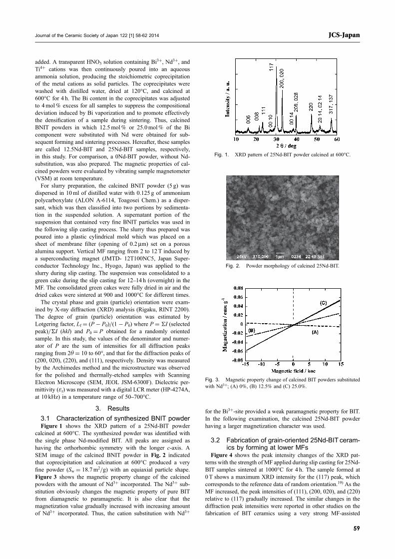
3.1 Characterization of synthesized BNIT powderFigure 1 shows the XRD pattern of a 25Nd-BIT powder
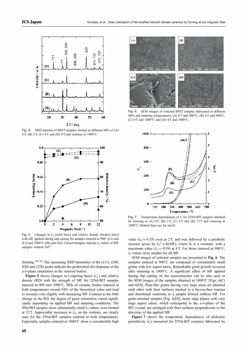
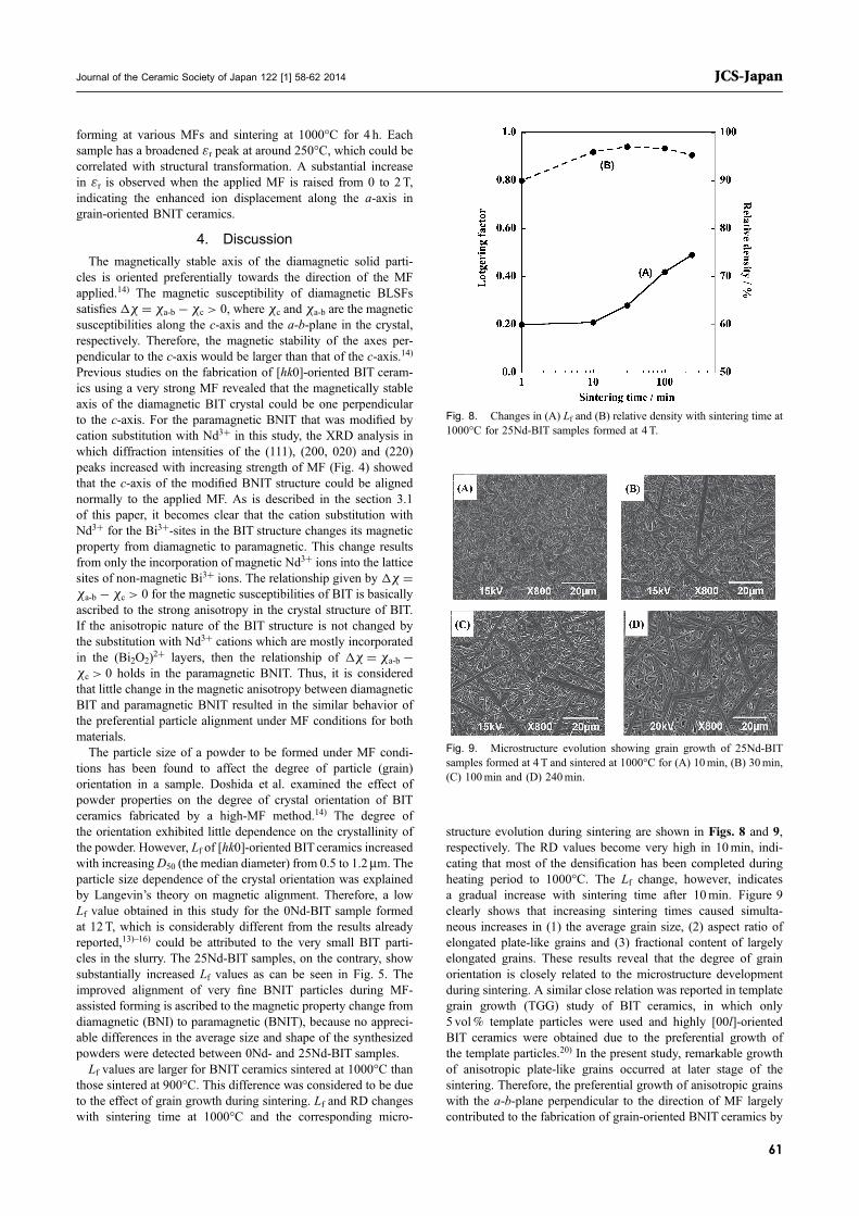
calcined at 600°C. The synthesized powder was identified withthe single phase Nd-modified BIT. All peaks are assigned ashaving the orthorhombic symmetry with the longer c-axis. ASEM image of the calcined BNIT powder in Fig. 2 indicatedthat coprecipitation and calcination at 600°C produced a veryfine powder (Sw = 18.7m2/g) with an equiaxial particle shape.Figure 3 shows the magnetic property change of the calcinedpowders with the amount of Nd3+ incorporated. The Nd3+ sub-stitution obviously changes the magnetic property of pure BITfrom diamagnetic to paramagnetic. It is also clear that themagnetization value gradually increased with increasing amountof Nd3+ incorporated. Thus, the cation substitution with Nd3+
for the Bi3+-site provided a weak paramagnetic property for BIT.In the following examination, the calcined 25Nd-BIT powderhaving a larger magnetization character was used.
3.2 Fabrication of grain-oriented 25Nd-BIT ceram-ics by forming at lower MFs
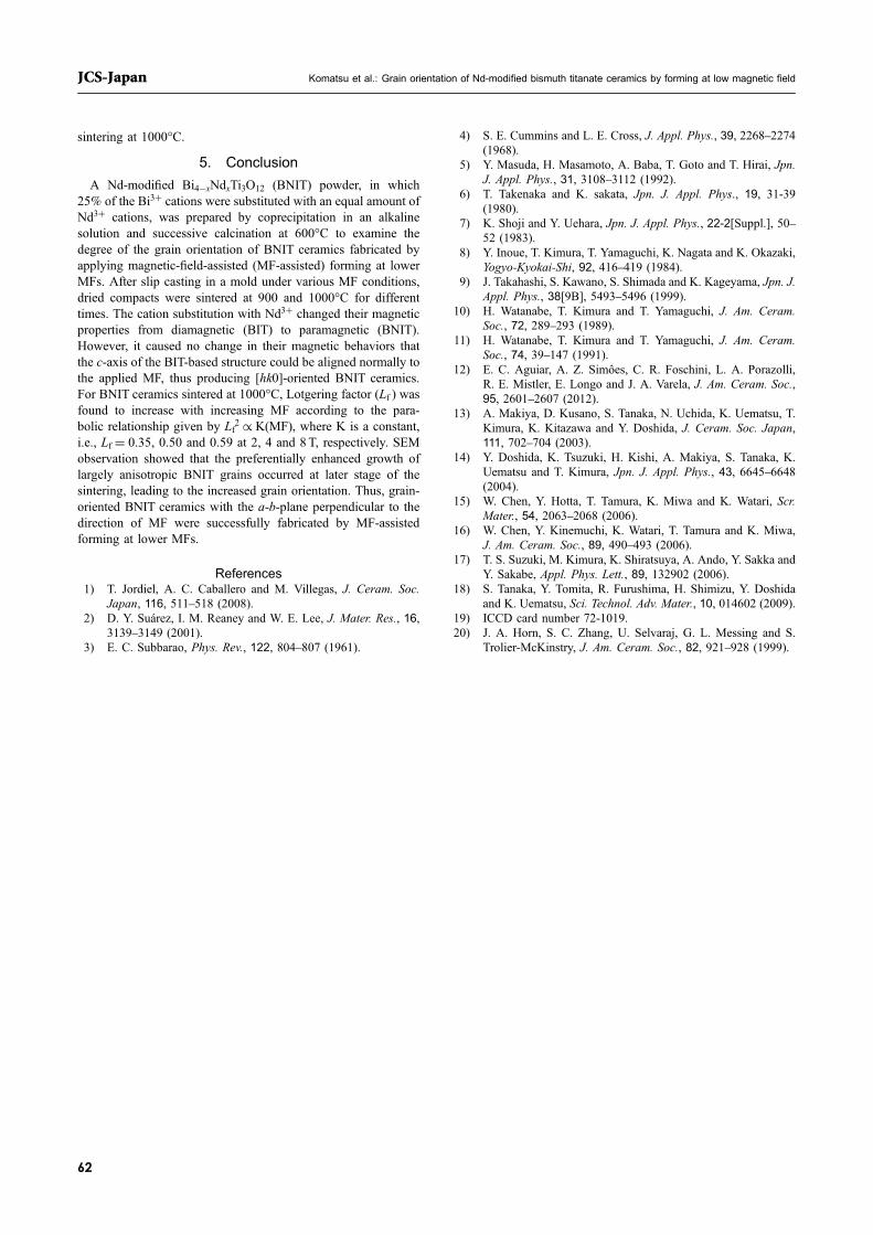
Figure 4 shows the peak intensity changes of the XRD pat-terns with the strength of MF applied during slip casting for 25Nd-BIT samples sintered at 1000°C for 4 h. The sample formed at0 T shows a maximum XRD intensity for the (117) peak, whichcorresponds to the reference data of random orientation.19) As theMF increased, the peak intensities of (111), (200, 020), and (220)relative to (117) gradually increased. The similar changes in thediffraction peak intensities were reported in other studies on thefabrication of BIT ceramics using a very strong MF-assisted
Fig. 1. XRD pattern of 25Nd-BIT powder calcined at 600°C.
Fig. 2. Powder morphology of calcined 25Nd-BIT.
Fig. 3. Magnetic property change of calcined BIT powders substitutedwith Nd3+; (A) 0%, (B) 12.5% and (C) 25.0%.
Journal of the Ceramic Society of Japan 122 [1] 58-62 2014 JCS-Japan
59
forming.14)16) The increasing XRD intensities of the (111), (200,020) and (220) peaks indicate the preferential development of thea-b-plane orientation in the sintered bodies.Figure 5 shows changes in Lotgering factor (Lf ) and relative
density (RD) with the strength of MF for 25Nd-BIT samplessintered at 900 and 1000°C. RDs of ceramic bodies sintered atboth temperatures exceed 94% of the theoretical value and tendto increase very slightly with increasing MF. Contrast to the littlechange in the RD, the degree of grain orientation varied signifi-cantly depending on applied MF and sintering conditions. The0Nd-BIT samples show substantially small Lf values, even formedat 12 T. Appreciable increases in Lf, on the contrary, are clearlyseen for the 25Nd-BIT samples sintered at both temperatures.Especially, samples sintered at 1000°C show a considerably high
value (Lf = 0.35) even at 2 T, and was followed by a parabolicincrease given by Lf2 £ K(MF), where K is a constant, with amaximum value (Lf = 0.59) at 8 T. For those sintered at 900°C,Lf values were smaller for all MF.SEM images of selected samples are presented in Fig. 6. The
samples sintered at 900°C are composed of considerably smallgrains with low aspect ratios. Remarkable grain growth occurredafter sintering at 1000°C. A significant effect of MF appliedduring slip casting on the microstructure can be also seen inthe SEM images of the samples obtained at 1000°C [Figs. 6(C)and 6(D)]. Plate-like grains having very large areas are attachedeach other with their surfaces stacked in a face-to-face mannerand distributed randomly in a sample formed without MF. Forgrain-oriented samples [Fig. 6(D)], many edge planes with verylarge aspect ratios, which correspond to the a-b-plane of theBIT crystal, are arranged with their surfaces perpendicular to thedirection of the applied MF.Figure 7 shows the temperature dependences of dielectric
permittivity (¾r) measured for 25Nd-BIT ceramics fabricated by
Fig. 4. XRD patterns of BNIT samples formed at different MFs of (A)0 T, (B) 2 T, (C) 4 T and (D) 8T and sintered at 1000°C.
Fig. 5. Changes in Lf (solid lines) and relative density (broken lines)with MF applied during slip casting for samples sintered at 900° [(A) and(C)] and 1000°C [(B) and (D)]. Closed triangles indicate Lf values of BITsamples without Nd3+.
Fig. 6. SEM images of selected BNIT samples fabricated at differentMFs and sintering temperatures; (A) 0T and 900°C, (B) 4T and 900°C,(C) 0 T and 1000°C and (D) 4T and 1000°C.
Fig. 7. Temperature dependences of ¾r for 25Nd-BIT samples obtainedby forming at (A) 0T, (B) 2 T, (C) 4 T and (D) 12T and sintering at1000°C (Dotted lines are for tan ¤).
Komatsu et al.: Grain orientation of Nd-modified bismuth titanate ceramics by forming at low magnetic fieldJCS-Japan
60
forming at various MFs and sintering at 1000°C for 4 h. Eachsample has a broadened ¾r peak at around 250°C, which could becorrelated with structural transformation. A substantial increasein ¾r is observed when the applied MF is raised from 0 to 2T,indicating the enhanced ion displacement along the a-axis ingrain-oriented BNIT ceramics.
4. Discussion
The magnetically stable axis of the diamagnetic solid parti-cles is oriented preferentially towards the direction of the MFapplied.14) The magnetic susceptibility of diamagnetic BLSFssatisfies ¦» = »a-b ¹ »c > 0, where »c and »a-b are the magneticsusceptibilities along the c-axis and the a-b-plane in the crystal,respectively. Therefore, the magnetic stability of the axes per-pendicular to the c-axis would be larger than that of the c-axis.14)
Previous studies on the fabrication of [hk0]-oriented BIT ceram-ics using a very strong MF revealed that the magnetically stableaxis of the diamagnetic BIT crystal could be one perpendicularto the c-axis. For the paramagnetic BNIT that was modified bycation substitution with Nd3+ in this study, the XRD analysis inwhich diffraction intensities of the (111), (200, 020) and (220)peaks increased with increasing strength of MF (Fig. 4) showedthat the c-axis of the modified BNIT structure could be alignednormally to the applied MF. As is described in the section 3.1of this paper, it becomes clear that the cation substitution withNd3+ for the Bi3+-sites in the BIT structure changes its magneticproperty from diamagnetic to paramagnetic. This change resultsfrom only the incorporation of magnetic Nd3+ ions into the latticesites of non-magnetic Bi3+ ions. The relationship given by ¦» =»a-b ¹ »c > 0 for the magnetic susceptibilities of BIT is basicallyascribed to the strong anisotropy in the crystal structure of BIT.If the anisotropic nature of the BIT structure is not changed bythe substitution with Nd3+ cations which are mostly incorporatedin the (Bi2O2)2+ layers, then the relationship of ¦» = »a-b ¹
»c > 0 holds in the paramagnetic BNIT. Thus, it is consideredthat little change in the magnetic anisotropy between diamagneticBIT and paramagnetic BNIT resulted in the similar behavior ofthe preferential particle alignment under MF conditions for bothmaterials.The particle size of a powder to be formed under MF condi-
tions has been found to affect the degree of particle (grain)orientation in a sample. Doshida et al. examined the effect ofpowder properties on the degree of crystal orientation of BITceramics fabricated by a high-MF method.14) The degree ofthe orientation exhibited little dependence on the crystallinity ofthe powder. However, Lf of [hk0]-oriented BIT ceramics increasedwith increasingD50 (the median diameter) from 0.5 to 1.2¯m. Theparticle size dependence of the crystal orientation was explainedby Langevin’s theory on magnetic alignment. Therefore, a lowLf value obtained in this study for the 0Nd-BIT sample formedat 12 T, which is considerably different from the results alreadyreported,13)16) could be attributed to the very small BIT parti-cles in the slurry. The 25Nd-BIT samples, on the contrary, showsubstantially increased Lf values as can be seen in Fig. 5. Theimproved alignment of very fine BNIT particles during MF-assisted forming is ascribed to the magnetic property change fromdiamagnetic (BNI) to paramagnetic (BNIT), because no appreci-able differences in the average size and shape of the synthesizedpowders were detected between 0Nd- and 25Nd-BIT samples.Lf values are larger for BNIT ceramics sintered at 1000°C than
those sintered at 900°C. This difference was considered to be dueto the effect of grain growth during sintering. Lf and RD changeswith sintering time at 1000°C and the corresponding micro-
structure evolution during sintering are shown in Figs. 8 and 9,respectively. The RD values become very high in 10min, indi-cating that most of the densification has been completed duringheating period to 1000°C. The Lf change, however, indicatesa gradual increase with sintering time after 10min. Figure 9clearly shows that increasing sintering times caused simulta-neous increases in (1) the average grain size, (2) aspect ratio ofelongated plate-like grains and (3) fractional content of largelyelongated grains. These results reveal that the degree of grainorientation is closely related to the microstructure developmentduring sintering. A similar close relation was reported in templategrain growth (TGG) study of BIT ceramics, in which only5 vol% template particles were used and highly [00l]-orientedBIT ceramics were obtained due to the preferential growth ofthe template particles.20) In the present study, remarkable growthof anisotropic plate-like grains occurred at later stage of thesintering. Therefore, the preferential growth of anisotropic grainswith the a-b-plane perpendicular to the direction of MF largelycontributed to the fabrication of grain-oriented BNIT ceramics by
Fig. 8. Changes in (A) Lf and (B) relative density with sintering time at1000°C for 25Nd-BIT samples formed at 4T.
Fig. 9. Microstructure evolution showing grain growth of 25Nd-BITsamples formed at 4 T and sintered at 1000°C for (A) 10min, (B) 30min,(C) 100min and (D) 240min.
Journal of the Ceramic Society of Japan 122 [1] 58-62 2014 JCS-Japan
61
sintering at 1000°C.
5. Conclusion
A Nd-modified Bi4¹xNdxTi3O12 (BNIT) powder, in which25% of the Bi3+ cations were substituted with an equal amount ofNd3+ cations, was prepared by coprecipitation in an alkalinesolution and successive calcination at 600°C to examine thedegree of the grain orientation of BNIT ceramics fabricated byapplying magnetic-field-assisted (MF-assisted) forming at lowerMFs. After slip casting in a mold under various MF conditions,dried compacts were sintered at 900 and 1000°C for differenttimes. The cation substitution with Nd3+ changed their magneticproperties from diamagnetic (BIT) to paramagnetic (BNIT).However, it caused no change in their magnetic behaviors thatthe c-axis of the BIT-based structure could be aligned normally tothe applied MF, thus producing [hk0]-oriented BNIT ceramics.For BNIT ceramics sintered at 1000°C, Lotgering factor (Lf ) wasfound to increase with increasing MF according to the para-bolic relationship given by Lf2 £ K(MF), where K is a constant,i.e., Lf = 0.35, 0.50 and 0.59 at 2, 4 and 8T, respectively. SEMobservation showed that the preferentially enhanced growth oflargely anisotropic BNIT grains occurred at later stage of thesintering, leading to the increased grain orientation. Thus, grain-oriented BNIT ceramics with the a-b-plane perpendicular to thedirection of MF were successfully fabricated by MF-assistedforming at lower MFs.
References1) T. Jordiel, A. C. Caballero and M. Villegas, J. Ceram. Soc.
Japan, 116, 511518 (2008).2) D. Y. Suárez, I. M. Reaney and W. E. Lee, J. Mater. Res., 16,
31393149 (2001).3) E. C. Subbarao, Phys. Rev., 122, 804807 (1961).
4) S. E. Cummins and L. E. Cross, J. Appl. Phys., 39, 22682274(1968).
5) Y. Masuda, H. Masamoto, A. Baba, T. Goto and T. Hirai, Jpn.J. Appl. Phys., 31, 31083112 (1992).
6) T. Takenaka and K. sakata, Jpn. J. Appl. Phys., 19, 31-39(1980).
7) K. Shoji and Y. Uehara, Jpn. J. Appl. Phys., 22-2[Suppl.], 5052 (1983).
8) Y. Inoue, T. Kimura, T. Yamaguchi, K. Nagata and K. Okazaki,Yogyo-Kyokai-Shi, 92, 416419 (1984).
9) J. Takahashi, S. Kawano, S. Shimada and K. Kageyama, Jpn. J.Appl. Phys., 38[9B], 54935496 (1999).
10) H. Watanabe, T. Kimura and T. Yamaguchi, J. Am. Ceram.Soc., 72, 289293 (1989).
11) H. Watanabe, T. Kimura and T. Yamaguchi, J. Am. Ceram.Soc., 74, 39147 (1991).
12) E. C. Aguiar, A. Z. Simôes, C. R. Foschini, L. A. Porazolli,R. E. Mistler, E. Longo and J. A. Varela, J. Am. Ceram. Soc.,95, 26012607 (2012).
13) A. Makiya, D. Kusano, S. Tanaka, N. Uchida, K. Uematsu, T.Kimura, K. Kitazawa and Y. Doshida, J. Ceram. Soc. Japan,111, 702704 (2003).
14) Y. Doshida, K. Tsuzuki, H. Kishi, A. Makiya, S. Tanaka, K.Uematsu and T. Kimura, Jpn. J. Appl. Phys., 43, 66456648(2004).
15) W. Chen, Y. Hotta, T. Tamura, K. Miwa and K. Watari, Scr.Mater., 54, 20632068 (2006).
16) W. Chen, Y. Kinemuchi, K. Watari, T. Tamura and K. Miwa,J. Am. Ceram. Soc., 89, 490493 (2006).
17) T. S. Suzuki, M. Kimura, K. Shiratsuya, A. Ando, Y. Sakka andY. Sakabe, Appl. Phys. Lett., 89, 132902 (2006).
18) S. Tanaka, Y. Tomita, R. Furushima, H. Shimizu, Y. Doshidaand K. Uematsu, Sci. Technol. Adv. Mater., 10, 014602 (2009).
19) ICCD card number 72-1019.20) J. A. Horn, S. C. Zhang, U. Selvaraj, G. L. Messing and S.
Trolier-McKinstry, J. Am. Ceram. Soc., 82, 921928 (1999).
Komatsu et al.: Grain orientation of Nd-modified bismuth titanate ceramics by forming at low magnetic fieldJCS-Japan
62