graphical menus for virtual environments - campus koblenzcg/studienarbeiten/sa_taekbongkim.pdf ·...
TRANSCRIPT

Student research project
Graphical Menus for Virtual Environments
Evaluation of Graphical User Interfaces for Immersive Environments
by
Taek-Bong Kim
Institute for Graphic Interfaces established by:
Fraunhofer IGD/ INI-GraphicsNet StiftungMinistry of Information and CommuntcationEwha Womans University
Tutor: Dipl. Inform. Timo Fleisch, Fraunhofer IGD DarmstadtExaminer: Prof. Dr. Stefan Müller, Universität Koblenz-Landau
July 2005

Zusammenfassung
Aus dem Einzug und der Verbreitung von Virtual Reality Anwendungen in verschiedenste Bereiche ergeben sich auch viele Probleme. Diese Umgebungen sind neu für die meisten Benutzer. Fremde Eingabegeräte, neue Ausgabegeräte und ungewohnte Interaktions-Methoden erschweren das agieren in diesen Anwendungen.
Eine wichtige Tätigkeit in jeder Computer Applikation ist die Steuerung des Systems. Befehle müssen gegeben, Zustände und Werkzeuge stetig gewechselt werden. Für diese Aktionen werden in 2D Anwendungen hauptsächlich grafische Menüs benutzt. Zusammen mit dem WIMP interface sind diese heutzutage in jeder Desktop-Applikation zu finden.
Menus sind logisch strukturiert. Sie übertreffen Kommandozeilen basierte Systeme dadurch, dass sie keine Erinnerungsleistung vom Benutzer erfordern. Alle Auswahlmöglichkeiten werden geordnet dargestellt und können unter Zuhilfenahme der Maus bequem und einfach selektiert werden. Dieses erfolgreiche Konzept macht sie heute zu einem Standart auf diesem Gebiet.
Aus diesen Gründen sind grafische Menüs eine naheliegende und interessante Option für virtuelle Umgebungen. Im Zuge dieser Studienarbeit werden 3D Interaktion und Benutzeroberflächen für diese Umgebungen untersucht und präsentiert.
Bei dem praktischen Teil handelt sich um die Erstellung des Interaktions-Moduls des Virtual Reality Frameworks AICI, welches beim Institute for Graphic Interfaces (IGI) in Seoul entwickelt wurde.
Dieses Modul erlaubt die Benutzung von 3D Menüs in virtuellen Umgebungen. Verschiedene Arten von 3D Menüs werden unterstützt, welche sich in Form, Verhalten und Bedienung voneinander unterscheiden. Die Menüs sind in erster Linie für virtuelle Umgebungen konzepiert. Das heisst, dass sie auf räumliche Eingabedaten reagieren und auf stereoskopischen Ausgabegeräten ausgegeben werden.
Sie sind aus Konfigurationsdateien erstellbar, welche keine Programmierkenntnisse erfordern. Die benutzte Syntax entspricht der, des bekannten XML. Dies gestaltet die Konzeption des Aussehens, der Struktur und der Funktionalität simpel und flexibel.
Die Studienarbeit wird abgeschlossen mit der Präsentation der Ergebnisse sowie Verbesserungsvorschlägen und einem Ausblick auf zukünfitge Arbeiten.

Table of Contents
1Introduction......................................................................................................................................... 1
2Theoretical Basics................................................................................................................................22.1Human Computer Interaction....................................................................................................... 2
2.1.1HCI in Virtual Environments...............................................................................................22.1.2Interaction in Virtual Environments.................................................................................... 3
2.1.2.1Navigation................................................................................................................... 32.1.2.2Selection/Manipulation............................................................................................... 42.1.2.3System Control............................................................................................................4
2.2The User Interface........................................................................................................................ 52.2.1A little history of User Interfaces........................................................................................ 6
2.2.1.1Command Line Interfaces........................................................................................... 62.2.1.2The WIMP metaphor...................................................................................................6
2.2.2Menus...................................................................................................................................82.2.3Graphical User Interfaces in Virtual Environments ............................................................9
3State of the Art.................................................................................................................................. 103.1Adapted 2D Menus.....................................................................................................................103.2The Pen and Tablet Metaphor.................................................................................................... 11
3.2.1Hand-held indirect Props................................................................................................... 123.2.2Hand-held direct Props...................................................................................................... 12
3.3Circular Menus........................................................................................................................... 133.3.1Pie Menus for VE.............................................................................................................. 133.3.2The Sundial Menus............................................................................................................ 14
3.4The Interaction Ball....................................................................................................................153.5Ring Menus................................................................................................................................ 153.6The Command and Control Cube ..............................................................................................173.7The TULIP Menu....................................................................................................................... 183.8Conclusion..................................................................................................................................19
4Practical realization.......................................................................................................................... 204.1Overview.................................................................................................................................... 204.2AIA - Advanced Industrial Applications....................................................................................204.3AICI – Advanced Immersive Collaborative Interaction Framework......................................... 21
4.3.1Motivation..........................................................................................................................214.3.2Structure.............................................................................................................................22
4.4Menu Module............................................................................................................................. 244.4.1Menu Items........................................................................................................................ 254.4.2The Menu ..........................................................................................................................25
4.4.2.1Identification and selection of items......................................................................... 254.4.3Menu creation.................................................................................................................... 264.4.4The Menu Configuration File............................................................................................ 274.4.5Factories.............................................................................................................................28
4.4.5.1Abstract factory.........................................................................................................284.4.6Handling of events............................................................................................................. 30
5Results and Future Work................................................................................................................. 32
i

Illustration IndexIllustration 1: HIT Lab's virtual emergency room ...................................................... 3Illustration 2: Machine-tool design review.................................................................. 3Illustration 3: Classification of system control techniques.......................................... 5Illustration 4: DIGITALs VT1000 from the late 70s...................................................6Illustration 5: A Command Line Interface...................................................................6Illustration 6: The Xerox Star System......................................................................... 7Illustration 7: Microsoft Windows XP desktop........................................................... 8Illustration 8: 3D Interaction with menu and Pinch Glove. (from [Jaco93]).............10Illustration 9: An Adapted 2D Menu in a VE............................................................ 10Illustration 10: The Personal Interaction Panel - PIP ................................................11Illustration 11: The Harlem Project. (from [Park01])................................................12Illustration 12: The 3D-fade-up menu. ( from [Deer95]).......................................... 13Illustration 13: A Pie Menu in 3D. ( from [Sant03])................................................. 14Illustration 14: Animated Icons. ( from [Sant03])..................................................... 14Illustration 15: Illustration 16: The Interaction Ball. (from [Haef99])...................... 15Illustration 16: A Sundial Menu. ( from [Shaw97]).................................................. 15Illustration 17: The Ring Menu used in JDCAD. ( from [Ljan94]) ..........................16Illustration 18: Gerbers Ring Menu in action ( from[Gerb04])................................. 16Illustration 19: Rotary Tool Chooser ( from ISAAC) ...............................................17Illustration 20: The Command and Control Cube......................................................17Illustration 21: The TULIP Menu. ( from [LiSi99]).................................................. 18Illustration 22: Structure of the ACIC core................................................................22Illustration 23: Configuration file for a Pie menu.....................................................26Illustration 24: The Abstract Factory Pattern.............................................................29Illustration 25: The menu module..............................................................................31Illustration 26: Menu in car reviewing application....................................................32Illustration 27: A pie menu........................................................................................ 34Illustration 28: Adapted 2D Menu............................................................................. 34Illustration 29: A Ring Menu ....................................................................................35Illustration 30: Ring menu with alternative look....................................................... 35
ii

1 Introduction
Designing a good User Interface is a difficult yet important defiance in every computer application. The aimed goal is to provide the user with all the functionalities a system offers, in a way that is easy to understand and intuitive to perform.
Graphical menus are an interaction technique which has been well studied and extensively used on desktop applications during the last decades.Fundamental advantages such as diminishing the cognitive load of the user by presenting all available options or easy to learn selection techniques in connection with the mouse, make menus highly effective and convenient to use for desktop applications. As a part of the popular WIMP interface it has become a self-established and standard interaction technique for 2D.
But recently more and more Virtual Environment applications find their way out of the research labs of scientists. The technique behind VR has become mature and non traditional devices and interface components are spreading rapidly. Spatial input devices such as trackers, whole-hand devices that allow gesture-based input, 3D pointing devices, stereoscopic projection displays, head-mounted displays, and haptic devices are currently widely used in many applications.But still interaction techniques in this kind of environments lack in usability. Positioning of graphical user interface elements, selection in 3D, various novel input devices, missing applicable metaphors and a lot of other problems which occur in Virtual Environments make the interaction a difficult and insufficient investigated research topic.
Therefore it would be convenient to use graphical menus in virtual environments since they have been examined and evaluated for a long time. But is the use of menus in virtual reality environments simply adoptable from desktop applications?
This student research project will try to answer this and more questions. It will introduce into relevant and basic theory, explain key terminology and will give an overview of the vast field of graphical user interfaces, especially menus used in virtual environments.
Finally, the practical implementation of a virtual reality framework module will be presented which is based on the acquired knowledge of the theory part. The module will consist of a graphical interface solution which is operated in Virtual Environments and is controlled by spatial input.
1

2 Theoretical Basics
2.1 Human Computer Interaction
The research field which focuses on the communication between the human and the computer is called Human Computer Interaction (HCI) whereas the human and human needs are in the center of interest. Following that, the basic goals of HCI are firstly, the improvement of interaction between users and computers, by making computers more user-friendly and easier to use, and secondly, to design the interaction methods in a way in that the user is able to accomplish his tasks efficiently. This research field is influenced by many interdisciplinary subjects such as design, psychology, ergonomics, human factors, cognitive science and others.
The process of HCI can be seen as users communicating actions, intents, goals, queries and other such needs to computers. Computers, in turn, respond information about the world, their internal state and answers to the user queries to the user.
2.1.1 HCI in Virtual Environments
Virtual Environments (VEs) depict environments which are simulated by a computer. VEs are interactive scenes which are seen from a first-person point of view. The most important feature of a VE is that it is immersive. That means that the sensation of being-there is created for the user. Virtual Reality (VR) is a synonym for this term and will therefore be used equally throughout this document.
With the technical advance of computer hardware a lot issues concerning tracking noise, rendering time, input devices and so on could be solved. That is to say, that the technique behind VEs is becoming sophisticated. As a consequence of that applications for VEs are spreading currently. The advantages of presenting, modifying and experiencing complicated multi dimensional datasets in these kind of environments have been recognized.
Complicated surgeries can be prepared, studied and taught without an expert locally present (see Illustration 1). Industrial product design processes can be shortened by creating and valuating digital models (see Illustration 2). Complicated and hard to conceive physical processes can be visualized. Architects can review their design results on a life-size model and form their opinions on issues like lighting and atmosphere.
2

These all are examples for existing 3D VE applications which support people from all different kind of areas.
With the propagation of these applications for VEs their use is no longer limited to computer scientists in research labs anymore. To a greater extend people get in touch with VEs. Users with no technical knowledge of the system interns have to work and solve tasks with these applications. That is why the applications have to be feasible and convenient to use, which is the challenge of the HCI research field, as stated above. HCI aspects have not yet been researched enough for VEs. Because of that users still have problems while interacting in VEs.
2.1.2 Interaction in Virtual Environments
Interaction in VEs is a domain of various different tasks. For a better overview they can be divided into three categories, like proposed in [BoKr04]:
• Navigation• Selection/Manipulation• System Control
2.1.2.1 Navigation
Navigation through 3D environments is a rudimentary action used constantly. It should provide the user with comfortable and efficient movement as well as support of spacial awareness. This task is a secondary task which means that the user should
3
Illustration 2: Machine-tool design reviewIllustration 1: HIT Lab's virtual emergency room

not have to think about how to move in order to focus on more important primary task. The navigation task is subdivided into the motor component called travel and the cognitive component called wayfinding.Travel is a conceptually simple task. The movement of the viewport from one location to another. Further, viewport orientation is usually handled in immersive VEs by headtracking. So only techniques for setting viewport positions need to be considered. Wayfinding can be described as the cognitive process of defining a path through an environment, thereby using and acquiring spatial knowledge to build up a cognitive map of an environment.
2.1.2.2 Selection/Manipulation
”Interaction techniques for 3D manipulation in VEs should provide means to accomplish at least one of three basic tasks: object selection, object positioning, and object rotation. Because direct hand manipulation is a major interaction mode not only in the 3D virtual world but also in natural physical environments, the design of interaction techniques for object selection and manipulation has a profound effect on the quality of the entire VE user interface. The classical approach to design manipulation techniques is to provide the user with a “virtual” hand – a 3D cursor, often shaped like a human hand, whose movements correspond to the movements of the hand tracker. Selection and manipulation simply involve touching an object, then positioning and orienting this virtual hand within the VE. The virtual hand technique is rather intuitive because it simulates a real-world interaction with objects, but only those objects within the area of reach can be picked up.” [BoKr04]
2.1.2.3 System Control
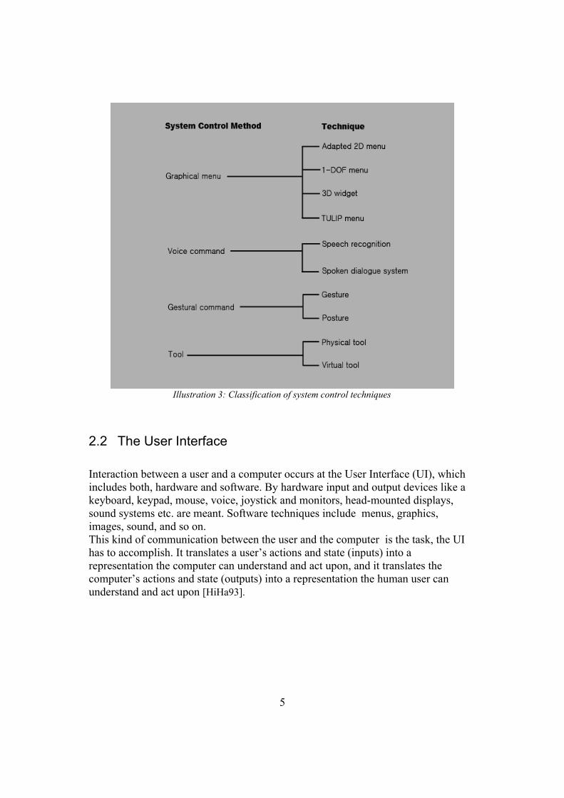
System Control can be explained as the action in which a command is applied to change either the mode of interaction or the system state [Krui00]. The issuing of a command always includes the selection of an element from a set. This can be achieved by different system control techniques like voice commands , gestural interaction (command sets accessed via gesture), tools (virtual objects with an implicit function or mode)and graphical menus (visual representations of commands) . Also, hybrid techniques exist that combine several of the types as well as multi-modal techniques which use different techniques simultaneously. All these techniques represent a User Interface of a system through which the HCI takes place. Illustration 3 shows the control technique classification from [Krui00]
4
2.2 The User Interface
Interaction between a user and a computer occurs at the User Interface (UI), which includes both, hardware and software. By hardware input and output devices like a keyboard, keypad, mouse, voice, joystick and monitors, head-mounted displays, sound systems etc. are meant. Software techniques include menus, graphics, images, sound, and so on. This kind of communication between the user and the computer is the task, the UI has to accomplish. It translates a user’s actions and state (inputs) into a representation the computer can understand and act upon, and it translates the computer’s actions and state (outputs) into a representation the human user can understand and act upon [HiHa93].
5
Illustration 3: Classification of system control techniques

2.2.1 A little history of User Interfaces
2.2.1.1 Command Line Interfaces
User interfaces have their own history and have gone through a lot of changes.
Back in the 1970s almost every interaction of the user with the computer was done by using the Command Line Interface (CLI). Basically the system displayed a prompt. The user then typed in a textual command (a sequence of characters) employing the keyboard, the only input device. The command was then executed by the machine. This interaction technique does not need high computer hardware capabilities like graphic cards. The monochrome displays and the keyboard where the hardware interface of these systems (see Illustration 4)
2.2.1.2 The WIMP metaphor
During the 1980s earlier achievements like the microprocessor and the more effective industrial production of computer hardware made the computer affordable by home users. The so called Personal Computer (PC) introduced by IBM became popular. Other technical improvements like raster graphics and the mouse as an input device paved the way for the first Graphical User Interfaces (GUIs). One of the first commercial system on the market was the Xerox Star System (Illustration 6). It supported a GUI with windows, icons and a complete desktop metaphor. In these times the research field of HCI gained more attention and importance.
6
Illustration 4: DIGITALs VT1000 from the late 70s
Illustration 5: A Command Line Interface

The design of UIs which enable the user with full control over the increasing functionality of the more and more evolved computer programs became a very important task.
This graphical interfaces with interaction based on pointing and clicking was easy to learn and effective to use. This so called WIMP interface was popularized by the Macintosh in 1984 . WIMP stands for “windows, icons, menus, pointing device” and has been the most prevalent GUI until our times. It has not changed radically until today, although it has been refined and surveyed a lot. The most popular and current example for this is the Microsoft Windows operating system used by millions of users worldwide (see Illustration 7) It has shown to be very effective and performant for 2D desktop jobs such as office tasks. Furthermore, the time required for learning of applications using the WIMP metaphor is short because they are quite self explaining. Users with almost no knowledge are able to perform simple tasks.
Due to its enormous popularity it has become the self established standard for interaction on desktop applications.
7
Illustration 6: The Xerox Star System

2.2.2 MenusOn the ongoings of these documents we are going to focus on special GUI elements, the menus.
As a crucial part of the WIMP interface, menus where jointly responsible for the success of this interface.
Menus present commands and options in a clear manner, usually in the shape of a list of commands. Menus take a lot of the cognitive load off the user. While before cryptic and long commands written in the right order had to be typed in, menus present all available options and therefore no memory effort is needed.
By using the mouse as an input device the user can easily point and click on wanted options, a very simple and fast selection technique. In most WIMP interfaces Pop-up and Pull-Down menus are supported. Moreover menus can be organized hierarchically which makes them capable for holding great numbers of commands.
As a consequence, menus offer a lot of advantages which make them also interesting as a 3D user interface for VE systems.
8
Illustration 7: Microsoft Windows XP desktop

2.2.3 Graphical User Interfaces in Virtual Environments
In desktop applications, the use of menus has received much attention.They have evolved to a fairly well understood state and exist in great number.
Unfortunately, menus are not always usable within a VE. One of the basic problems of selection in a VE and interacting in general, is that a normally one- or two-dimensional task becomes three-dimensional, which reduces the effectiveness of traditional techniques. For example, touching a menu item floating in space is much more difficult than selecting a menu item on the desktop, not only because the task has become 3D, but also because the important constraint of the physical desk on which the mouse rests is missing.
Such problems, different hardware setups and different objectives led to various graphical 3D menu approaches.
The next chapter will give an overview of interesting attempts of using old and new menu forms and selection techniques in VE.
9

3 State of the Art
3.1 Adapted 2D Menus
One approach to use 2D menus in VE is to display the menus on 3D geometry. [Jaco93] uses pull-down menus consisting of a set of text labels which are rendered on thin rectangles. The user performs a gesture and the menu appears at the users hand location. The selection of a menu item is done using a ray cast through the finger of the worn Data Glove (Illustration 8). There exist more placement possibilities of menus in 3D environments than on a 2D screen. [Fein93] introduced 2D Menus for augmented reality environments which could be displayed in three different modes. The surround-fixed windows are displayed at a fixed position in the world, display-fixed windows are displayed at a fixed location relative to the user's
head orientation and world-fixed windows are fixed locations or objects which are invocable by the user. [MiBr95] suggests the use of human proprioception for easy access to menus. He hides menus in locations fixed relative to the user's body. In that way menus are easier to find and access by the user. One example for this are the pull-down menus which are literally pulled down from above the users head. Cascading Menus are also realized in several VE applications (see [Teyl97], [Jaco93]).However the effectiveness of this traditional
10
Illustration 9: An Adapted 2D Menu in a VE
Illustration 8: 3D Interaction with menu and Pinch Glove. (from [Jaco93])
techniques is reduced in virtual 3D environments. One reason is that the normally two-dimensional selection technique used in 2D menus becomes three-dimensional. Pointing at items and menus in free space is therefore more difficult than it is on the desktop [BoKr01]. Another problem is that 3d pointers and other input devices for VE usually do not support any haptic feedback like one has with the mouse on the desk. That leads to missing precision and exhaustion.
3.2 The Pen and Tablet Metaphor
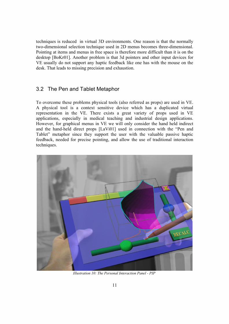
To overcome these problems physical tools (also referred as props) are used in VE. A physical tool is a context sensitive device which has a duplicated virtual representation in the VE. There exists a great variety of props used in VE applications, especially in medical teaching and industrial design applications. However, for graphical menus in VE we will only consider the hand held indirect and the hand-held direct props [LaVi01] used in connection with the “Pen and Tablet” metaphor since they support the user with the valuable passive haptic feedback, needed for precise pointing, and allow the use of traditional interaction techniques.
11
Illustration 10: The Personal Interaction Panel - PIP

3.2.1 Hand-held indirect Props
The hand-held indirect props are usually notebook sized, tracked tablets or panels. Depending on the VE system setup the tablet has to be transparent. First used in the HARP system by [LiSi99], the panel is held in the non dominant hand, on which a menu in form of text labels is projected. The dominant hand performs fine actions like picking and selecting items by using the index finger or a stylus. The non-dominant hand, which holds the panel, can bring the menu into the viewport whenever needed. This two handed interaction style is a very natural and intuitive interaction technique. Empirical tests have been made for the HARP testbed in [LiHa99]. They show that passive haptic feedback, given by the tablet, can significantly increases the user performance. This paradigm has gained a quite big popularity on Responsive Workbench applications. Transparent panels are used so that the menu mask appears on or slightly above the tablet. In addition to menus, also widgets like sliders and buttons are commonly used, like in [Schm99], [Szla99] (Illustration 10). Some approaches even support manipulation and other interaction tasks through this panel using the 2D projection of the 3D scene [Coqu99]. But since these fall out of scope they will just left mentioned here.
3.2.2 Hand-held direct Props
Another prop used in semi immersive VE are the direct hand-held props. These devices allow the user to interact in 2D on their display surfaces. 2D tasks like menu interaction are mapped to 2D devices and 3D tasks to the 3D devices. An example 2D device used for this task is a hand-held computer like a PDA (Illustration 11). It displays menus and other 2D widgets with which the user interacts directly on the display surface. The data is propagated ideally via a wireless communication with the system in order to grant an unlimited movement of the user. This technique was introduced by [Wats99] where the PDA was used to control camera, environmental and geometrical parameters. Other projects enhanced the 2D GUI but basically used the same interaction technique [Park01]. The familiarity of the user with the look
12
Illustration 11: The Harlem Project. (from [Park01])

and feel of the 2D interface is the big advantage of this concept.
3.3 Circular Menus
Other approaches use different shaped menus instead of the rectangular form. What so all, this idea is not a new one. Pie shaped menus have already been used in several 2D applications and evaluated (see [Hopk91], [Call88]). Some research has been done on these menus and a lot of approaches exist. Sub menu realization, short selection time and self explaining interfaces are just a few features of this menu types.
3.3.1 Pie Menus for VE
A simple realization of a disk formed menu is the 3D-fade-up menu system interface used in the Holosketch system [Deer95] (Illustration 12). They present the available commands in the form of 3D objects and icons. They are all arranged to the shape of a circular plate. The menu items of a same group are arranged closely together and marked in the same color. Single commands can then be selected by simply pointing on the target icon, as known from the traditional interfaces.
13
Illustration 12: The 3D-fade-up menu. ( from [Deer95])

Currently the majority of the pie menus used in VE consist of only one ring of icons. The disk is separated into equal segments which stand for a command (Illustration 13). The user pushes a button and the menu pops up. By doing a movement in a specific direction the according menu item in that direction is selected. Precise pointing at a certain area is not required anymore which is great advantage in usability since it is a troublesome task in VE as already mentioned above. More complex implementations of the pie menu support hierarchical organization of the menu entries. The sub menu is then shown with its center above the parent item. Animated icons showing 3d model icons are also used for previewing the outcome of the commands for 3d modeling application as used in the Smart Sketches project [Sant04] (Illustration 14).
3.3.2 The Sundial Menus
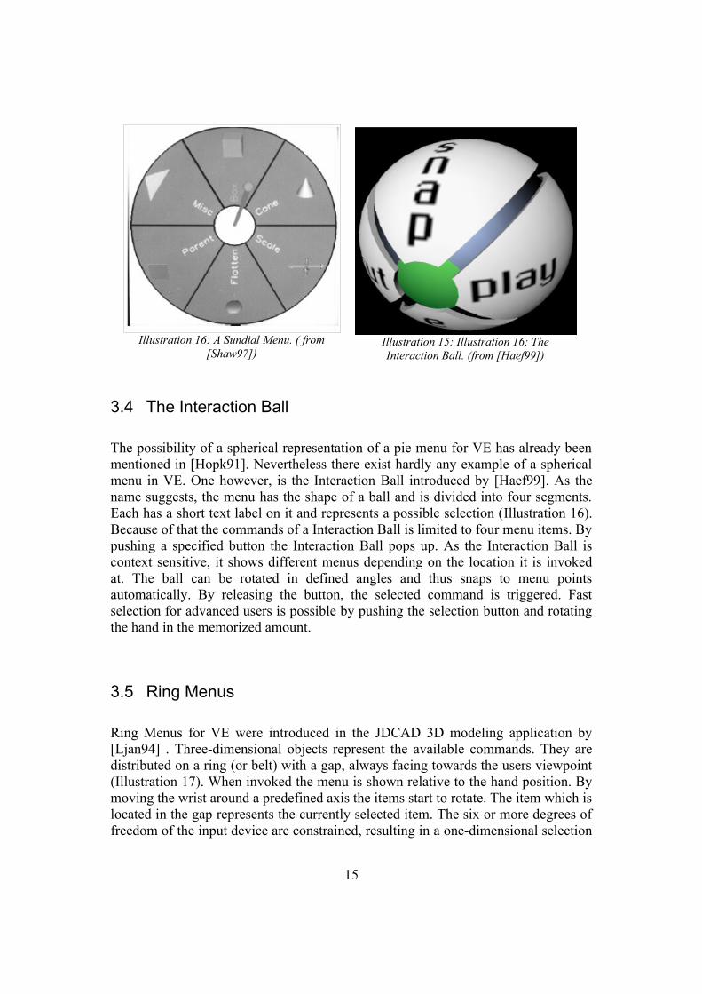
A slightly different selection technique and form is the Sundial menus which are used in several applications, e.g. in [Shaw97] or in [Eber96]. The menu choices are arrayed on the circular plate of the sundial, each on its own pie-shaped sector (Illustration 15). The desired item is picked by pivoting the shadow stick about its base so that the stick's endpoint lies visually in front of the sector. The base of the shadow stick is located at the center of the plate, and when the menu first pops up, the stick is aligned with the line of sight, pointing directly at the user. Around the base of the stick is an inner circle which the user can point the stick at to indicate no selection. The position of the sundial is fixed rigidly to the bat, and the dial lies parallel to the screen.
14
Illustration 13: A Pie Menu in 3D. ( from [Sant03])
Illustration 14: Animated Icons. ( from [Sant03])
3.4 The Interaction Ball
The possibility of a spherical representation of a pie menu for VE has already been mentioned in [Hopk91]. Nevertheless there exist hardly any example of a spherical menu in VE. One however, is the Interaction Ball introduced by [Haef99]. As the name suggests, the menu has the shape of a ball and is divided into four segments. Each has a short text label on it and represents a possible selection (Illustration 16). Because of that the commands of a Interaction Ball is limited to four menu items. By pushing a specified button the Interaction Ball pops up. As the Interaction Ball is context sensitive, it shows different menus depending on the location it is invoked at. The ball can be rotated in defined angles and thus snaps to menu points automatically. By releasing the button, the selected command is triggered. Fast selection for advanced users is possible by pushing the selection button and rotating the hand in the memorized amount.
3.5 Ring Menus
Ring Menus for VE were introduced in the JDCAD 3D modeling application by [Ljan94] . Three-dimensional objects represent the available commands. They are distributed on a ring (or belt) with a gap, always facing towards the users viewpoint (Illustration 17). When invoked the menu is shown relative to the hand position. By moving the wrist around a predefined axis the items start to rotate. The item which is located in the gap represents the currently selected item. The six or more degrees of freedom of the input device are constrained, resulting in a one-dimensional selection
15
Illustration 16: A Sundial Menu. ( from [Shaw97])
Illustration 15: Illustration 16: The Interaction Ball. (from [Haef99])

technique which is very easy to control. However, in this initial form the few items which fit into the ring is the main drawback of this system. If choosing the ring to large it is difficult to reach all the items for the user in an acceptable time, if the items are located too close together, right selection is troublesome. The ring menu implemented by [Gerb04] follows the same concept of selecting by a one-dimensional technique, but uses a slightly different graphical representation. Equally shaped boxes act as menu items. They are located into a unclosed ring of 160 degrees with its wide gap facing the user (Illustration 18). The rotation is constrained so that the boxes never occlude each other. That is done because here the selected item lies at the back end of the ring. It is enclosed by an highlighting selection frame around the box. If an item represents a parent node to a sub menu a second ring is opened behind the initial ring. Now the wrist rotation of the user is mapped onto the sub menu ring. Because of the clear arrangement of the boxes, opened sub rings are still clearly visible. In that way more commands can be provided by the ring menu and ordered hierarchically.
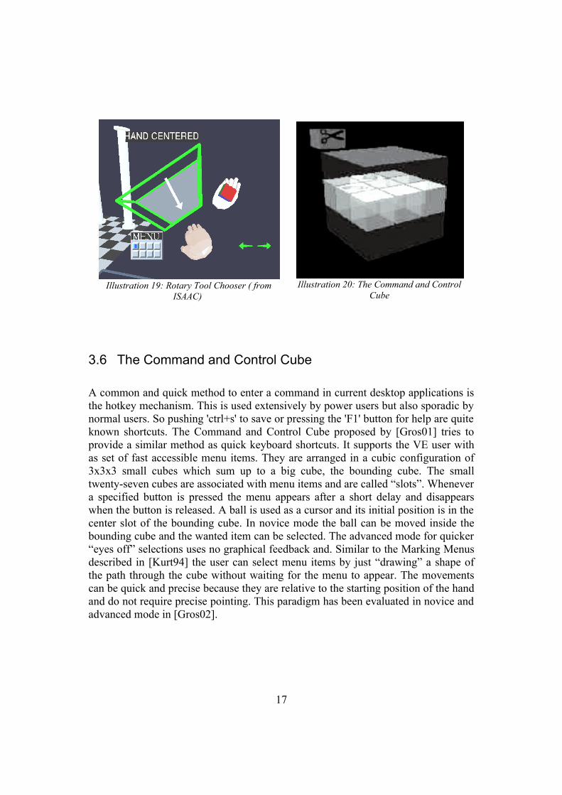
A similar one-dimensional menu example is the Rotary Tool Chooser (RTC). It was used in the ISAAC project by [Mine95] to select tools or trigger commands. The tools appear in an arc around the user's hand when a certain button is pushed. By keeping the button pushed and turning the hand around a predefined axis (like turning a dial) the tools slide past a selection box. A tool is selected when it falls within the selection box. Only changes along the chosen dimension are critical in the selection process of the tool, all other changes are ignored. Like mentioned before this one-dimensional technique simplifies interaction with the rotary tool chooser.(Illustration 19)
16
Illustration 17: The Ring Menu used in JDCAD. ( from [Ljan94])
Illustration 18: Gerbers Ring Menu in action ( from[Gerb04])
3.6 The Command and Control Cube
A common and quick method to enter a command in current desktop applications is the hotkey mechanism. This is used extensively by power users but also sporadic by normal users. So pushing 'ctrl+s' to save or pressing the 'F1' button for help are quite known shortcuts. The Command and Control Cube proposed by [Gros01] tries to provide a similar method as quick keyboard shortcuts. It supports the VE user with as set of fast accessible menu items. They are arranged in a cubic configuration of 3x3x3 small cubes which sum up to a big cube, the bounding cube. The small twenty-seven cubes are associated with menu items and are called “slots”. Whenever a specified button is pressed the menu appears after a short delay and disappears when the button is released. A ball is used as a cursor and its initial position is in the center slot of the bounding cube. In novice mode the ball can be moved inside the bounding cube and the wanted item can be selected. The advanced mode for quicker “eyes off” selections uses no graphical feedback and. Similar to the Marking Menus described in [Kurt94] the user can select menu items by just “drawing” a shape of the path through the cube without waiting for the menu to appear. The movements can be quick and precise because they are relative to the starting position of the hand and do not require precise pointing. This paradigm has been evaluated in novice and advanced mode in [Gros02].
17
Illustration 19: Rotary Tool Chooser ( from ISAAC)
Illustration 20: The Command and Control Cube

3.7 The TULIP Menu
Other solutions differ more significantly from the traditional menu metaphor like the TULIP menu proposed and evaluated by [BoWi01]. This menu requires a special input device, the Pinch Glove which tracks the position of the user's hand and manages sensitive buttons for each finger. The Non-dominant hand controls the menus while the dominant hand controls the menu items. Each item is displayed next to a finger. An item is selected by pinching the relevant finger with the thumb. By design, the number of items in one menu is 4, but menus can be split into sub-menus to allow the more items. This menu is recommended in connection with a HMD system, because the menu needs to be displayed near or above the user's fingers which complicates the occlusion problem. Empirical tests showed that the users prefer this menu due convenience reasons.
18
Illustration 21: The TULIP Menu. ( from [LiSi99])

3.8 Conclusion
Different interaction metaphors and techniques for graphical menus in VE have been presented. The great variety shows that there has not been found an perfect solution for all tasks.
Different menus are used under different conditions. Some require a special input device like the TULIP menus and others are limited in the number of accessible commands.
The hand-held direct and indirect props in connection with the pen and tablet metaphor seem to be very promising as already stated by [LaVi01].
Nevertheless, it would be highly desired to find an graphical menu interface which makes real use of spatiality and provides intuitive interaction techniques which do not depend on a specific input devices. A menu that is capable and a good choice for all kinds of VE setups.
But seeing the present variety of menus it seems that finding such a solution is a very hard and currently not possible task, because no standards neither in input and output devices nor in interaction techniques and metaphors exist.
19

4 Practical realization
4.1 Overview
For the practical part of this student research project a module, capable of presenting various menu styles used in VEs, had to be implemented. These menus form a 3D user interface for VE applications through which the user is able to control system states and trigger commands directly in a spatial context.
However, this menu module is not a separate object. It depends on other modules whose interplay form a fundamental VR framework, the Advanced Immersive Collaborative Interaction library toolkit, or short AICI. This framework is developed within the scope of the Advanced Industrial Application (AIA) Project at the Institute for Graphic Interfaces (IGI) in Seoul.
The following chapter will give an outline of the work and goals of the AIA-team. After that the AICI toolkit will be shortly introduced and finally the menu module will be described in detail.
4.2 AIA - Advanced Industrial Applications
The development cycle of a new industrial product is a tedious process. It requires a lot of expertise form various kind of specialists. Designers, engineers, managers, costumers and many other groups of people, constantly express and exchange their thoughts, ideas and concerns during this process. It is a process which consumes a lot of time as well as financial resources in a great amount.
Nowadays, VR technology has made great improvements. Hardware interfaces become more an more evolved, input and output devices accurate and usable. Computer visualizations have reached a realistic state and physical simulations feign realistic, physical correct behavior. Seeing that, VE applications can be of great use in a lot of areas, especially in the aforementioned industrial product design. Digital mockup building, design reviewing applications, and stream line visualization are just a few examples for reasonable VE applications on this sector. The goal of the AIA-team is to provide these kind of systems to the Korean industry in order to raise the effectiveness of industrial product development.
20

4.3 AICI – Advanced Immersive Collaborative Interaction Framework
4.3.1 Motivation
Since the designation of the AIA project implicates the emergence of various new VR applications, it would be highly desired to have a VR library as a framework which is capable of all basic tasks. Tasks every application for a VE will utilize like the appropriation of a UI, input and output device managing, eventhandling, and so on. For instance the developer of a 3D modeling application does not want to rack his brains how to render the graphical output stereoscopic. The AICI framework is developed for such purposes.
The AICI library consists of several modules which enable the user to create applications for VE. It is based on OpenSG which is a portable scenegraph system to create real-time graphic programs and is therefore well suited for the AICI needs. There exist other scene graph based toolkits like Performer, Open Inventor and Java3D. Nevertheless OpenSG is used in the AICI library because of the following reasons. Firstly, OpenSG is developed following Open Source principles and its source code can be freely studied and used. This accessibility makes this API easy to extend for the own needs. Furthermore heterogeneous networks are supported, in that way multiple computers with different hardware setups, namely graphic cards can run the same application. The greatest advantage is the ability to handle a cluster of rendering PCs and multi-threaded data structures in a very easy and high performant way.
However, OpenSG is not supposed to be a complete VR system. It is the rendering basis on top of which VR systems can be built. Because of that the AICI library provides additional modules in order to be a library toolkit for VR applications based on OpenSG.
21
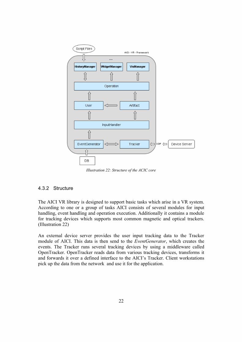
4.3.2 Structure
The AICI VR library is designed to support basic tasks which arise in a VR system. According to one or a group of tasks AICI consists of several modules for input handling, event handling and operation execution. Additionally it contains a module for tracking devices which supports most common magnetic and optical trackers. (Illustration 22)
An external device server provides the user input tracking data to the Tracker module of AICI. This data is then send to the EventGenerator, which creates the events. The Tracker runs several tracking devices by using a middleware called OpenTracker. OpenTracker reads data from various tracking devices, transforms it and forwards it over a defined interface to the AICI’s Tracker. Client workstations pick up the data from the network and use it for the application.
22
Illustration 22: Structure of the ACIC core

While raw tracker data alone is principally sufficient for 3D applications, for complex 3D interaction a more convenient programming model is desirable. Interaction programming usually relies on event distribution, so an adopted event-driven model was chosen as well. The EventGenerator creates the 3D events and passes them to the InputHandler.
The InputHandler gets 3D events containing tracking data such as position and orientation from the EventGenerator. The data can be fed into the scenegraph as a sequence of 3D-events, and can therefore be picked up and used by any other class. To distinguish different sources of the tracking data the device ID of the event source device is stored inside the event. Additionally each device has to be assigned to a dedicated user. Depending on the device the event is passed to the appropriate user and artifact event handling operations.
A tracked physical Input device can be connected with one Artifact class. The Artifact class has its own event handling mechanism. Dedicated Artifact Operations can be registered with an instance of an Artifact. Each time the Artifact receives an event it passes the event to all registered operations.For example the tracked device for the head tracking has an operation registered that updates the position of the camera each time it receives an event.
In AICI there are two types of Operation:
• UserOperation
• ArtifactOperation
The UserOperation class is the parent class for all operations executed by the user while working with the application. Examples for UserOperations are the saving of a file or drawing a curve.
While an operation is active it receives the events created by the input device assigned for interaction. By that the operation is reacting to the user input.
The UserOperation have to be registered with the OperationFactory. By that an operation can be easily created by its identification name.
An ArtifactOperation has to be registered to an Artifact. While registered the Artifact passes the received events further to the ArtifactOperation. Integrated in AICI there are already ArtifactOperations for an instance for the pen artifact, the scene navigator artifact and the head tracking artifact.
All visual elements used to control the application are called widgets. Each widget in AICI has to be registered and created by the WidgetManager. The
23

WidgetManager receives events from the specific artifact operation of the device which is supposed to run the widgets. The event is passed to each active widget unless one widget declares it as used. If a event is used, for example because of the user clicked a button, the event is not further proceeded, that means, it is not passed to an active operation.
Each registered widget will check if the received event is an action addressed to it. If yes, then it will react accordingly and mark the event as used.
The VisManager is related with all 3D visualization. Therefore, it supports window and viewport creation, scene creation, viewer-centered perspective calculations, displaying to multiple graphics channels, and transform geometry etc.
4.4 Menu Module
As stated before, system control is a sensitive task in VEs. The right UI and interaction technique is searched which enables the user to access and control the system and its state. Example tasks are the loading and saving of scenes or the activation of certain tools.
Input and output devices, the physical user interface of the system, differ highly form devices the user is accustomed to from desktop applications, like the keyboard and the mouse. The AICI library wants to stay flexible and applicable in different VE setups, hence does not want to supply a special input device for controlling the system. Instead, very general attributes of the input device are demanded; a tracked 6 DOF device and a trigger, like a button. These are requisites that almost every VE system setup features.
Following the state of the art results, different menu styles should be supported. Regarding the hardware requirements and the interaction mode a subset of the different menus used in current VE applications has been chosen. The adapted 2D menus, a Ring Menu similar to [Gerb04], and a Pie Menu supporting both, novice and advanced mode.
Because these different menu types should be supported, it is necessary to define the style and look of the menus as well as the structure in a convenient way. Therefore a configuration file in XML syntax will be used.
24

4.4.1 Menu Items
A menu item is a component of a menu. On an abstract level, the menu item is an entity in the list of items the menu administrates.
Each menu item has a geometry which represents the item graphically in virtual space. Later eventual intersection test are done on this geometry for selecting. Its geometric properties also represent the states of the item, e.g. highlighting of the material. This kind of behavior is usually defined in the onTouch() function of the item.
Of course every item can be activated after selection. The triggered action is assigned in the execute() function which is then called. Usually every item is instantiated with an string. This string is the name of a registered operation which is then created and called by the OperationFactory.
Because menu items for different kind of menus differ in form and behavior the classes are but still share the same interface they are derived from a parent class MenuItem. The concrete implementations are done in a separate classes, the RingMenuItem, PieMenuItem, and CascadeMenuItem class.
Sub menus are also derived from menu items. That is because they share the same features as the other items. The only difference is that they have the ability to hold other menu items. On demand these list of items is shown or hidden.
4.4.2 The Menu
The Menu is the central object of this module. A menu consists of a collection of menu items and sub menus. The menu is responsible for presenting these items correctly. The items and sub menus are added to the menu with the addItem() function. Another task of the menu is to manage incoming events on which it reacts according to the menu style used. All menu types have to be derived from the abstract parent class Menu. CascadingMenu, RingMenus, and PieMenu are all such concrete implementations.
In the following two main processes of menus will be explained.
4.4.2.1 Identification and selection of items
If during the runtime of the menu, geometry of a menu item is picked, the menu has to know which geometry belongs to which menu item instance. Therefore a special labeling technique is required. Every added item is given an Id from the IdServer. The use of the IdServer ensures that the given Id is unique and not assigned to any
25
other object yet. The Id is then set to the item as the node name of the geometry node. After that, the name is stored into a map the menu owns, the menuItemsMap. A map is a Standard Template Library (STL) Container storing two different kinds of elements. The first element is the search key and the second the actual data element which should be found by the key. The menuItemsMap holds the Id of an item as a key and a pointer to the menu item as the data element. In that way a geometry can be identified by searching the menu item instance by using the node's name as the key.
4.4.3 Menu creation
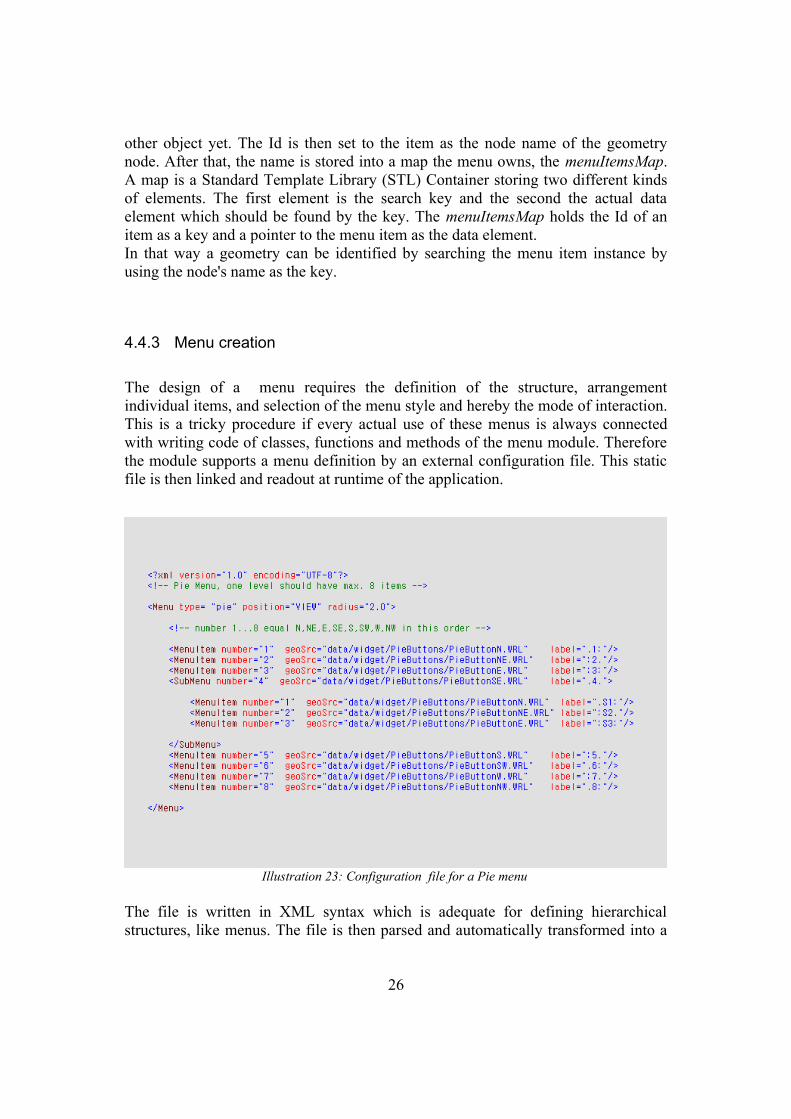
The design of a menu requires the definition of the structure, arrangement individual items, and selection of the menu style and hereby the mode of interaction. This is a tricky procedure if every actual use of these menus is always connected with writing code of classes, functions and methods of the menu module. Therefore the module supports a menu definition by an external configuration file. This static file is then linked and readout at runtime of the application.
The file is written in XML syntax which is adequate for defining hierarchical structures, like menus. The file is then parsed and automatically transformed into a
26
Illustration 23: Configuration file for a Pie menu

equivalent menu instance. In that way the complete menu creation is controlled by one file which makes this whole process convenient, uncomplicated and flexible for the application developer.
4.4.4 The Menu Configuration File
Illustration23 shows an example for a configuration file of a pie menu. It is written in the syntax of the Extensible Markup Language (XML), a language designed to describe data. It is a standard recommended by the W3C. Its syntax is well structured and easy to learn. Because of the extensive use of this language in the Internet it is well documented and there exist various tools for the use of XML. It is highly extensible by allowing the definition of own arbitrary tags and structures, and is therefore well suited for the defined purposes.
A menu definition file always begins with the start tag <Menu> and the end tag </Menu>. The start tag can have attributes which define general properties of the menu. The type attribute defines which type of menu is created, in this case a pie menu. The position attribute determines the positioning style. Available options are VIEW for view-fixed positioning, PEN or positioning depending on the input device location, and FIXED for a fixed situation in space.Additionally, there are other attributes available, depending on the kind of menu. E.g. for the pie menu of the example a radius can be specified.
The start tag is followed by a list of <MenuItem> and <SubMenu> entries. Menu items are instanced with a number starting by 1. According to this number and the chosen menu type they are located in the menu. The number 1 in a pie menu means the north position whereas in a ring menu it is the first element from the left. The item's geometry is loaded from the location of the geometry file. This path is written into the geoSrc attribute. Selectively they can carry either an icon (iconSrc) or a textual name (label ) for distinction. Sub menus poses the same attributes as the other menu items. But surrounded by their start and end tags, sub menu items and other sub menus can be defined.
<SubMenu ...></MenuItem ...>...
</SubMenu>
27

4.4.5 Factories
Another but also important issue of menu creation is to guarantee the construction of the menus with fitting items and sub menus. To assure this factories are used, oriented at the Abstract Factory pattern.
4.4.5.1 Abstract factory
The menu module supplies an UI that supports multiple look-and-feel standards, such as the Ring Menu , the Pie Menu, and other menus. Different look-and-feels define different appearances and behaviors for user interface components like menus, sub menus, and buttons. Dependencies have to be enforced between the concrete menu component classes. A ring menu e.g. should consist of ring sub menus and ring menu items.
To be portable across look-and-feel standards, an application should not hard-code its parts for a particular look and feel. Instantiating look-and-feel-specific classes of widgets throughout the application makes it hard to change the look and feel later.
Therefore the MenuFactory class is defined following the Abstract Factory pattern [GaHe95]. An abstract factory provides an interface for creating families of related or dependent objects without specifying their concrete classes. The structure of this idea is shown in Illustration 24.
Therefore the MenuFactory declares an interface for creating each basic kind of menus and its according components. MenuFactory's interface has an operation that returns a new Menu object for each abstract menu class.
Clients like the widget manager call these operations to obtain menu instances, but aren't aware of the concrete classes they are using. They just work with the interface of the abstract factory class. Thus clients stay independent of the prevailing look and feel.
28

There is a concrete sub class of MenuFactory for each look-and-feel standard. Each subclass implements the operations to create the appropriate widget for the look and feel. That means for instance that the createMenuItem() function called with a MenuFactory of the type RingMenuFactory instantiates and returns a RingMenuItem object while a PieMenuFactory would return a PieMenuItem. In that way the WidgetManager only has to commit to an interface defined by the abstract MenuFactory class, not a particular concrete class.
Each menu has to be registered and created by the WidgetManager. When initialized, the widget manager loads the specified configuration file to create the menu. The file is then parsed by an additional library, the Xerces-C++ (www.apache.org) in order to access the information of the file. The function createMenuFromXML(file) then utilizes a factory instance of the type defined in the configuration file. The other steps of menu construction are then passed to the concrete factory object, which instantiates the menu, creates the items and sub menus according to the attributes. The items and sub menus are then added to the menu and a reference pointer of the object is then returned to the WidgetManager. There it is registered and the geometry is added to the scene graph by passing the handle of its subtree to the VisManager. After that the menu is running and ready for input and eventhandling.
29
Illustration 24: The Abstract Factory Pattern

4.4.6 Handling of events
The WidgetManager receives events from the artifact operation of the input device which was assigned to operate the menu. In that way it is granted that the input comes from the designated input device. As long as no widget declares the event as used it is passed to every active widget. Otherwise the event will not be proceeded to active operations. After widgets have checked if the received event is an action addressed to it they react accordingly and mark the event as used.
In order to distinguish if the menu is addressed or not, one button of the tracking device is reserved and marked as the menu button. Whenever the eventhandling of the menu receives an event, the status of this button is checked first.
In the case in which the button is not pushed the menu stays inactive. The GUI of the menu stays hidden and input has no influence on it. The incoming events are marked unused and further proceeded to eventually other graphical widgets and operations. For the period in which the button is pressed, the menu is in active state. It reacts on the users input data provided from the pen. Usually, the GUI of the menu is made visible first. Just in the case of the Pie Menu, it stays nonetheless invisible for a split second on order to distinguish whether non graphical advanced mode or the novice mode with graphical feedback is desired.
For the next step the eventhandling updates its data for position and orientation of the input device. These are directly read out of the event. For most menu types a collision detection is made. It has to be determined if a geometry belonging to the menu has been hit or not. There are several different selection techniques. For the traditional and the pie menus a ray-casting technique has been implemented. A point intersection has not been used because exact pointing in free space without haptical feedback is a quite difficult task, as mentioned in state of the art (3.1).
The gained 3D position of the event represents the position of the input device. With its orientation and position a ray is calculated and rendered. It has the same orientation as the input device and has its origin at the tip of the device. After that a ray intersection test is done with the objects of the geometries of the menu. If something is hit, the according MenuItem instance to the geometry is identified as explained in (4.4.2). The hit item is then marked as the currently selected item and the onTouch() method of the item is executed (usually highlighting).
30

If the button is released while resting on an item, the operation assigned to this item is executed.
The RingMenu requires no collision detection, because it is uses a 1DOF selection technique. The movements of the pen are simply mapped to a rotation of the menu items. They all pass a fixed selection box. The item which is currently in the selection box is marked as selected and is triggered when the button is released.
Illustration 25 shows the main parts and the structure of the menu module and its interaction with other library components. It also illustrates the actual conversion of the abstract factory pattern.
31
Illustration 25: The menu module

5 Results and Future Work
Within the scope of this student research project, interaction in virtual environments using 3D menus has been examined in theory and has been realized practically.
An introduction has been given into the field of 3D interaction and important terminology like Human Computer Interaction and User Interfaces has been
explained. Graphical menus have been classified in the vast field of 3D interaction. And finally a complete state of the art on graphical menus for VEs has been elaborated. It shows, that various different menu types are currently in use in VE applications. It does not exist a always one fitting standard solution.
Therefore, in the practical part a subset of the 3D menus, namely traditional menus, ring menus, and pie menus, have been chosen and realized in a menu module for the virtual reality library toolkit AICI. The menus are intended to be used in VE applications, thus they react on and work with spatial input data provided from tracked input devices.
Menu definition was designed to be highly configurable and flexible. Therefore a extern configuration file in the adaptable XML syntax is used.The configuration file arranges the structural definition of a menu. Item names, sub menus, order of items and their functions can be composed freely. In addition to that different look-and-feels can be created. This cannot only be done by changing between the different menu types as mentioned above. Also the geometry of the menu and its items can be assigned in the configuration file. Virtually any 3D geometry can be used. In that way the look of the menu can change from application to application.
This module for creating and employing 3D menus has been presented. Nevertheless there are some open questions and refinements that can be done for the future. Due to the architecture of the menus and its components, it can be easily extended by other graphical menu types. Therefore it would be interesting to implement also other menu types, existing or new invented ones.
32
Illustration 26: Menu in car reviewing application

A multi-modal user interface is an interesting promising approach and still an open field of research. So in combination with the menus, other inputs like voice or gesture could be considered to be integrated into the framework.
Finally user tests and evaluations on menus have to be made. 3D menus have not been compared and evaluated sufficient yet in computer science. Since various kinds of menus can be used in the presented library, it is well suited for user tests and evaluation. Unfortunately this could not be completed during this project, because of time reasons.
33

34
Illustration 27: A pie menu
Illustration 28: Adapted 2D Menu

35
Illustration 29: A Ring Menu
Illustration 30: Ring menu with alternative look

Bibliography
[BoKr01] D. A. Bowman, E Kruijff, J LaViola and I Poupyrev: “An Introduction to 3D User Interface Design”. Teleoperators and Virtual Environments vol.10, no. 1, 2001
[BoKr04] D. A. Bowman, E Kruijff, J LaViola and I Poupyrev: “3D User Interfaces – Theory and Pratice”. Addison Wesley, 2004
[BoWi01] D. A. Bowman and C. A. Wingrave: “Design and Evaluation of Menu Systems for Immersive Virtual Environments”. Proc. of IEEE Virtual Reality, 2001.
[Call88] J. Callahan, D. Hopkins, M. Weiser and Ben Shneiderman: “An Empirical Comparison Of Pie vs. Linear Menus”. Proc. CHI'88 Conf. on Human Factors in Computing Systems, ACM Press, 1988.
[Coqu99] S. Coquillard and G. Wesche: “The Virtual Palette and the Virtual Remote Control Panel: A Device and an Interaction Paradigm for the Responsive Workbench”. IEEE Virtual Reality'99 Conference - VR'99, 1999.
[Deer95] M. F. Deering: “Holosketch: a virtual reality sketching animation tool”. ACM Transactions on Computer-Human Interaction, 1995.
[Eber96] D. Ebert, C. Shaw, A. Zwa and C. Starr: “Two-handed interactive stereoscopic visualization”. Proceedings IEEE Visualization, 1996
[Fein93] S. Feiner, B. MacIntyre, M. Haupt and E. Solomon: “Windows on the World – 2D Windows for 3D Augmented Reality”. Proceedings of the 6th annual ACM symposium on User Interface software and technology - UIST'93, ACM Press, 1993.
[GaHe95] E. Gamma, R. Helm, Ralph Johnson and John Vlissides: “Design Patterns “. Addison-Wesley Professional, 1995
[Gerb04] D. Gerber and D. Bechmann: “Design and evaluation of the ring menu in Virtual Environments”. Proc. of 8th International Immersive Projection Technology Workshop, IPT'04, 2004.
[Gros01] J. Grosjean and S. Coquillart: “Command and Control Cube: a Shortcut Paradigm for Virtual Environments”. In Immersive Projection Technology and Virtual Environments - IPT-EGVE'2001 pp. 1–12, 2001.
[Gros02] J. Grosjean, J. Burkhardt, S. Coquillart and P. Richard: “Evaluation of the Command and Control Cube. Evaluation of the Command and Control Cube” Proc. of International Conference on Multimodal Interfaces, IEEE, 2002.
[Haef99] U. Haefner, A. Simon and M. Doulis: “Evaluation of Complex CAD Data in a Virtual Environment”. International Immersive Projection Technology Workshop – IIPTW'99, 1999.
[HiHa93] D. Hix, H. Rex Hartson “Developing User Interfaces : Ensuring Usability Through Product & Process” Wiley Professional Computing, 1993

[Hopk91] D. Hopkins: “The Design and Implementation of Pie Menus”. Published in Dr. Dobb's Journal, 1991.
[Jaco93] R. H. Jacoby and S. R. Ellis: “Using virtual menus in a virtual environment”. Proceedings of SPIE, Visual Data Interpretation, 1992.
[Kurt94] G. Kurtenbacher and W. Buxton: “User Learning and Performance with Marking Menus”. Proc. of the SIGCHI conference on Human factors in Computing Systems, ACM, 1994.
[Krui00] E. Kruijff: “System Control”. Siggraph course on 3D User Interface Design, ACM Press, 2000.
[LaVi01] J. LaViola: ”Bringing 2D Interfaces into 3D Worlds”. Siggraph course – Advanced Toopics in 3D User Interface Design, 2001.
[LiHa99] R. W. Lindeman, J. L. Silbert and J. K. Hahn: “Towards Usable VR: An Empirical Study of User Interfaces for Immersive Virtual Environments”. Proc. of SIGCHI '99, ACM Press, 1999.
[LiSi99] R. W. Lindeman, J. L. Sibert and J. K. Hahn: “Hand-Held Windows: Towards Effective 2D Interaction in Immersive Virtual Environments”. Proceedings of IEEE Virtual Reality, pp. 205-212, 1999.
[Ljan94] L. Ljang, M. Green: “JDCAD: A highly interactive 3D modeling system”. Computer and Graphics 18(4) pp. 499-506, 1994.
[MiBr95] M. R. Mine, F. P. Brooks Jr. and C. H. Sequin: “Moving Objects in Space: Exploiting Proprioception in Virtual Environments”. Proc. of SIGGRAPH ‘97 Conference, 1997.
[Mine95] M. R. Mine: “ISAAC: A Virtual Environment Tool for the Interactive Construction of Virtual Worlds”. UNC Chapel Hill Computer Science Technical Report TR95-020, 1995.
[Park01] S. K. Park, J. Leigh, A. E. Johnsson, B. Carter, J. Brody, and J. Sosnoski: “Distance learning classroom using Virtual Harlem”. In Proc. of the 7th Intern. Conf. on Virtual Systems and Multimedia (VSMM 2001), pages 489–498 , 2001.
[Reid84] P. Reid: “Work Station Design”. Fundamentals of Human-Computer Interaction, Academic Press, 1984.
[Sant04] P. Santos and A.Stork: “SmartSketches: A Multimodal Approach to Improve Usability in the Early States of Product Design”. International Society Technologies Programme – IST-2000-28169, 2004.
[Schm99] D. Schmalstieg, L. Miguel Encarnacao and Z. Szalavari: “Using Transparent Props For Interaction With The Virtual Table”. ACM Symposium on Interactive 3D

Graphics – I3DG'99, 1999.
[Shaw97] C. D. Shaw and M. Green: “THRED: a two-handed design system”. Multimedia Systems, Springer Verlag, 1997.
[Szal99] Z. Szalavari: “The Personal Interaction Panel a two-handed Interface for Augmented Reality”. Dissertation, Technische Universitaet Wien, Eurographics Digital Library, 1999.
[Teyl97] R. van Teylingen, W. Ribarsky and C. van der Mast: “Virtual Data Vizualizer”. IEEE Transactions on Visualization and computer Graphics, VOL. 3, NO. 1. , 1997.
[Wats99] K. Watsen, R. P. Darken and M. Capps: “A Handheld Computer as an Interaction Device to a Virtual Environment”. Proceedings of the International Projection Technology Workshop, 1999.