graphical techniques for aircraft dynamic model development
TRANSCRIPT

American Institute of Aeronautics and Astronautics
1
Graphical Techniques for Aircraft Dynamic Model Development
Paul A. Barnard* The MathWorks, Natick, MA 01760, USA
The complexity and expense of modern aircraft development programs drives the need for mathematical models of aircraft dynamic behavior at all stages in a design cycle. The limitations of graphical tools have meant that many system engineers have continued to rely on the historical practice of developing models using FORTRAN or C, a tedious and error-prone approach. Often, the reuse of models from stage to stage is limited or difficult, creating the possibility that differences in the models could exist and leading to incorrect results. Today’s well established, commercial off-the-shelf (COTS) products free designers from the need to create, manage, and understand models written in textual programming languages. These products provide a unified environment in which designers can model all system dynamic characteristics accurately.
I. Introduction Modeling and simulation tools have been in use since the 1920s, but until recently these tools were nongraphical
in nature and inadequate to capture the entire complex dynamic behavior of modern systems. As a result, many designers continue to rely on traditional programming methods and mathematical models.
Developing models using FORTRAN or C is not only tedious but also error-prone; inadvertent changes can
occur when models are reused at different stages of the design, leading to incorrect results. Similarly, the documents typically used to communicate requirements, specifications, test scenarios, and other content between groups frequently are subject to ambiguity and misinterpretation.
With today’s well established, COTS graphical modeling tools, system designers no longer need to create,
manage, and understand models written in textual programming languages. All system dynamic characteristics can be modeled accurately in a graphical, block diagram form. The model is also the documentation, which means that designs can pass directly from the desktop to pilot training simulations without introducing errors and with minimal manual effort. Since all models used in the design process are captured in one environment, the designer can readily access them to repeat a previous analysis.
At a minimum, the model can be used as a specification that contains greater detail than text -based
specifications. When graphical models are used with Model-Based Design, they bring additional benefits. Model-Based Design provides an efficient approach to four key elements of the development process:
requirements capture, design, implementation, and test. It is not necessary to use Model-Based Design for all these elements to see measurable advantages, but when it is used to its fullest, Model-Based Design enables developers to use a single model of their entire system—both the physical system and the controller—for data analysis, model visualization, testing and validation, and product deployment, reducing error and saving development time and costs.
II. Evolution of Graphical Techniques Aircraft vehicle and system models are among the most challenging to develop. When systems are safety-
critical, the smallest error could cause catastrophic results. Because of the cost and complexity of these systems, there is less opportunity to prototype than there is in other industries and more need to “get it right” the first time.
* Control Design Automation Marketing Director, 3 Apple Hill Drive

American Institute of Aeronautics and Astronautics
2
Unlike other systems, aircraft systems must account for multiple variables—wind, turbulence, weather, etc—and six degrees of freedom that interact in sometimes unpredictable ways. The explosion of electrical systems, avionics, and software adds to the complexity.
Simulation techniques evolved to address the unique challenges of dealing with complex engineering systems.
They have been particularly valuable in aircra ft development. Until 1950, these were exclusively analog techniques1. With the development of digital computers in the mid-1950s, researchers began exploring digital simulation. By 1967, more than 23 different simulation programs were available, including MIMIC, from Wright Patterson; DYNASAR, from General Electric; DSL/90; and CSMP, from IBM.
The CSSL report commissioned by the Simulation Council Inc was a major milestone, since it unified the
concepts and language structures of the available simulation programs. Several simulation products were based on this standard, notably ACSL, which added to CSSL a macro language, built-in operators, control statements, and constructs for combined continuous and discrete modeling.
The limited input-output facilities of early digital computers made it necessary to revert to textual representations
in the digital simulators. Prototype graphical environments were available by the mid-1970s, but graphical modeling was not widely used until modern work stations and the PC with raster graphics became generally available.
Boeing’s simulator EASY5 was among the first modeling tools to be provided with a graphical user interface.
This was followed by SystemBuild (1984), VisSim (1990), Simulink® (1991), and the ACSL Graphical Modeller (1993).
The new generation of graphical tools, such as the recently released Simulink 6, covers all aspects of design.
These tools are unified graphical modeling environments that include features such as interactive graphical editors, graphical debuggers, and model analysis and diagnostics tools. They enable the designer to manage complex designs by segmenting models into hierarchies of design components. They include a customizable set of block libraries that allow engineers to accurately design, simulate, implement, and test control, signal processing, communications, and other time-varying systems.
III. Using Graphical Tools in Model-Based Design Model-Based Design is the most effective way to leverage the rich functionality provided by the new generation
of graphical tools. It can be used within any development process, such as the “V” diagram, waterfall or spiral process. It covers all aspects of development, including specifications based on requirements, high-level (system-level) design, low-level (subsystem-level) design, implementation, and testing (including verification and validation).
At the heart of Model-Based Design is a model which is not only the repository for all information about the
concept and design but also the design imp lementation. At the heart of the model is an algorithm consisting of block diagrams and state machines, each with specific timing and real-time execution characteristics. The algorithm is often combined with environmental components to produce a complete executable system. Components include sensors, actuators, mechanical devices, dynamic vehicles, electronics, and other physical elements that interact with the algorithm.
The model starts as an idealized representation during the requirement capture, and then details are added as the
design progresses. Changes or corrections to the system requirements and specifications are easily incorporated into the model, fully evaluated by simulation, and automatically reflected in the final real-time embedded software. The model can be executed at any point, so ambiguity is reduced and errors can be detected and addressed earlier in the process, when they are easier and less costly to fix. The result of the mo deling elaboration can lead directly to automatically generated implementations, documentation, test scenarios and harnesses, and other art ifacts.
A. Requirements and Specifications Using one of the new graphical modeling environments with Model-Based Design lets engineers coordinate,
track, communicate, and implement changes in design specifications throughout the development process. One can access requirements stored in formal requirements management systems, such as DOORS, or in Microsoft Word,

American Institute of Aeronautics and Astronautics
3
Microsoft Excel, or HTML-formatted files, and associate them with blocks, subsystems, states, transitions, functions, and truth tables within the models.
By associating these requirements with components of the model, designers can rapidly navigate and iterate
between requirements documentation, design, and model imple mentation. While documentation is no longer the primary way to convey information in the design process, it still has important roles in Model-Based Design. The model can be mapped to the requirements document so that it is clear what parts of a design are impacted if a requirement changes (and what requirements are impacted if component design changes).
Documentation can also be used to communicate the system behavior and intents to others in the development
process, such as test engineers.
B. Design Detailed software design begins once the system and software requirements have been specified using the
models. Graphical modeling tools like Simulink and Stateflow® work in a hierarchical fashion, enabling you to manage complex models by breaking them down into functional elements of arbitrary size and structure. Designers can achieve multiple levels of model fidelity by simply substituting one model element for another.
An open platform, such as that provided by MATLAB® and Simulink, can incorporate models of system
components and operating conditions implemented in C, FORTRAN, and specialized mo deling tools, such as mechanical dynamics for a mechatronics system or noise models in a signal processing application. This provides the designer with a richer context in which to design the system or subsystem.
The modeling tool can encapsulate legacy or highly optimized code, facilitating the reuse of that code into more
projects and enabling the use of Model-Based Design for projects in which only a portion of the system is being redesigned or added.
A key to innovative design is to be able to quickly try, evaluate, and revise a design, often through rapid
prototyping. Because the models are executable and can also be quickly converted into code to run on a real-time system, Model-Based Design is ideal for this phase. Rapid prototyping gives the designer a sandbox in which to try new ideas and evaluate their effectiveness. It can be performed in several ways: by running the simulation on a host computer in a non-real-time mode, by running a simulation on a system that executes in real time but bears little resemblance to the eventual target, to enable the evaluation of different approaches, by running on a system very similar to the eventual target or on the target itself.
C. Implementation Because the same model is being elaborated, it is easier for someone working earlier in the process (for example,
an algorithm designer) to collaborate with the person doing the implementation (such as the software engineer) and ensure that the implementation meets the goals of the design. Once the model is built and completely tested, accurate real-time software for the production embedded design is automatically generated, saving time and reducing costs.
Production code generation technology has evolved rapidly in recent years. This has resulted in more use of this
technology across embedded control and signal proces sing development. That increased usage, in turn, has driven further refinements of the technology, including tool usability, efficiency of the generated code, flexibility for tailoring the code format, and the ability to integrate automatically generated code with legacy and hand-generated code.
Often process and methodology planners try to strictly enforce a boundary between rapid prototyping and
implementation so that the design approach and the addition of implementation details are not mixed. But there has been increasing success in blurring that boundary. Organizations are finding that the ability to add implementation details – and to do prototype implementations on the production target architecture, for example – enables them to detect design flaws earlier in the development phase, when they are easier and less costly to fix2.
To be effective for both rapid prototyping and implementation, the development tools need to have the ability to
hold and utilize implementation details (for example, fixed-point representation) in the model and then allow the

American Institute of Aeronautics and Astronautics
4
user to ignore these details for simulation and analysis or to use them for implementation. Alternately, the platform must have the ability to easily swap in representations of different fidelity (with or without the implementation details).
D. Test With Model-Based Design – and its use of executable models – tes ting happens every time a model is simulated,
and thus is an integrated aspect of the design process. This leads to a broader and more encompassing role for verification and validation. (Verification confirms that work products properly reflect the requirements specified for them. Validation confirms that the product, as provided, will fulfill its intended use.)
Model-Based Design fosters design flows that move validation into the early part of a software life cycle,
reducing the risk of late error detection. For example, rapid prototyping helps tune parameters and check the functional behavior of an algorithm using a real-time computer and plant hardware.
One of the main tenets of Model-Based Design is that the model used for simulation needs to match the results
from the code execution. Advanced simulation environments such as Simulink allow engineers to create and execute bit-true simulations; integrate high-performance MATLAB algorithms ; maintain target-independence through out the design; maintain test-ready simulations; and provide direct implementation and verification paths to a multitude of hardware options through automatic prototype and production code generation, co-simulation, and hardware-in-the-loop prototyping.
Having good models of the design also impacts other aspects of testing. For example, running simulations of the
model provides information about model coverage that helps testing groups to determine which aspects of the implementations are covered by equivalent tests. Test data and vectors can be generated for use in test harnesses, either directly from the requirements or based on the design. This is particularly valuable for systems that contain large amounts of logic, where designing test sequences is particularly difficult .
IV. Example of Graphical Tools Used Within Model-Based Design In this example, the ideas presented above are applied to the development of a model and the associated control
system for the HL-20 lifting body. The HL-20 was developed as a backup system for the space shuttle and a crew return vehicle for the international space station3. In one scenario, the HL-20 was to be used as a life-boat for the crew of the international space station in the event of an emergency. In that case, this craft could be boarded and automatically flown to a safe landing on earth at a conventional runway. For the purposes of this example, a control system was developed from NASA specifications4 that implemented the final decent and landing profile for the vehicle. The vehicle model includes the aerodynamics, control logic, fault management systems (FDIR), and engine controls (FADEC). It also includes effects of the environment, such as wind profiles for the landing phase.
The development of a system as complex as the HL-20 is beyond the capability of one or two people. Solving
this control problem requires multiple design teams working together toward a common set of requirements and specifications. Subsystems are developed separately in teams before being integrated together to meet higher-level requirements. Teams designing controllers have to work with teams designing the physical system components. Model-Based Design can be invaluable in solving this type of problem, meeting schedule milestones and system performance.
Following is a description of how Model-Based Design was used in the development of this system. Particular
aspects of graphical modeling are applied to this problem. These aspects are common to other types of aerospace systems as well. Simulink 6 and the Simulink product family were used as the basis for developing this example. The top-level model for the HL-20 is shown in Fig. 1.

American Institute of Aeronautics and Astronautics
5
Figure 2. Aerospace Blockset provides aerospace component models for initial configuration design and requirements development.
A. Requirements and Specification During the requirements
definition phase of a project, models can be invaluable in capturing the thoughts and ideas of the system developers. The models can help synthesize the system in a way that is more realistic than simply sketching ideas on paper. In our example, we used blocks from the Aerospace Blockset, shown in Fig. 2, to quickly prototype ideas for modeling the HL-20. This block library contains simple models for common aerospace systems, such as equations of motion, flight dynamics, propulsion, actuators, GNC, and environmental effects. With these predefined blocks, it is straightforward to quickly create a system model from
Figure 1. The HL-20 system model expressed in Simulink.

American Institute of Aeronautics and Astronautics
6
Figure 3. Avionics subsystems capture the architecture of the system including component signal specifications. Two avionics bays are modeled here with the left bay containing redundant CPUs B and C.
which you can test out vehicle configurations and performance. In the initial stages of the project, it is common for subsystem components to be incompletely defined. The RF
Signals subsystem from Fig. 1 is an example of such a component. The RF Signals subsystem is essentially a shell that will be filled in later in development. We don’t yet know the details of how the radar altimeter will work, but we do know that it will be specified in this system component. We define inputs, outputs, and signal attributes, but not the details. The use of graphical tools that support hierarchy enable this type of flexibility when it comes to model fidelity. The ability to add detail to the model at different stages of development is key to efficient engineering.
In refining the initial requirements for this system, models can be developed that capture the thoughts and ideas
of the system architects as well. As the project moves from requirements gathering to specification, the concepts of the system architects can be included in the model –the very same model that was used by the initial configuration designers. Interfaces between components can be specified using data busses that can strictly define the signals that need to pass between components. Information about the rate of data transfer and types of signals can be specified at this point. The system can also be expressed as a series of separate models that are to be aggregated into an overall system model for testing. Breaking down the model into components facilitates component-based development, allowing several teams to work on individual components in parallel. Figure 3 shows how this was accomplished for the specification of redundant CPUs in separate avionics bays.

American Institute of Aeronautics and Astronautics
7
Figure 4. Lookup tables implementing the aerodynamic model through measured coefficients.
B. Design Leveraging graphical
models in the design phase of a project is most effective when the graphical models can be simulated. Defining the semantics of the graphical models in a way that allows complete mathematical execution of the diagrams ensures that the models correctly express the engineer’s concept. Without being able to simulate or execute the diagrams, graphical techniques are nothing more than a better way to document your ideas. Simulation verifies that your diagrams include consistent data and mathematics. It also helps ensure that critical components are included in your design – even if they are initially only placeholder components.
Because graphical models must simulate the world they represent, it is important to leverage both measured real-world data and first-principles modeling techniques. Each serves a different purpose during development. First principles modeling involves such activities as deriving equations of motion and analyzing force and moment diagrams. It also can involve simply knowing which mechanical, electrical, or hydraulic components make up a system. Modeling from measured data involves system identification methods and expressing block components as tables or polynomials. In our example, we use both types of modeling. First principles were used to model basic elements of the vehicle model, such as the combination of aerodynamic, thrust, and landing gear forces summing to the total forces and moments applied to the vehicle. In the aerodynamic subsystem, however, we used wind tunnel data applied through efficient table lookup blocks to model the flight characteristics. This data was taking from the NASA Technical Memorandum5 detailing the subsonic aerodynamics for the HL-20. Figure 4 shows the subsystem implementing the multidimensional table lookup blocks for this model. Note that common indices (AlphaIdx and BetaIdx) are calculated and applied to all the lookup tables, since the data was measured with the same angle-of-attack and sideslip values. This approach results in a highly efficient implementation of the lookup table algorithms.
Control design is a critical part of the design work at this stage in the process. The controller must be designed to
provide robust stability throughout the vehicle flight envelope. The graphical techniques used to describe the model must also extend to the control design phase to ensure that accurate models of the system are applied. Linearization and other tools are needed to extract a form of the (generally) non-linear model that can be used with linear control design tools.

American Institute of Aeronautics and Astronautics
8
Design should proceed in conjunction with simulation to derive the maximum benefit from the models built in the specification stage. The simulation, however, must work with various domains of system expression. The block diagram notation traditionally used in the control design world has found its way in to other applications, such as signal processing and communications systems. State machines have also been useful in describing logic for controllers, and many control systems are dominated by state logic. Figure 5 illustrates a Stateflow diagram depicting some of the logic used in the fault detection, isolation, and recovery algorithm for the control surface actuators of the HL-206.
As systems have become more complex7, detailed modeling of the physical systems being controlled has increased in importance. Modern graphical simulators can simulate all of these different domains together in a single environment. This is an advantage over linking multiple simulators together in a co-simulation mode because the state dynamics of one domain can radically affect another domain. It takes a single simulator to aggregate all of these effects properly to accurately model the system dynamics.
C. Implementation The implementation phase of the project is where the largest gain can be realized from Model-Based Design.
The technology of automatic code generation from graphical diagrams has evolved to the point where efficiency and readability of the code now match or exceed that of hand code for complex applications8. Software engineers can use the options and flexibility of the code generator to create the exact type of code required. Typically, these engineers must ensure that the code matches corporate standards and interfaces with modules that may still be written by hand.
In the HL-20 example, code was generated from the Simulink model using Real-Time Workshop® Embedded Coder, which generates highly efficient code for use in safety-critical and production embedded systems. The options provided by the tool allow for complete customization of the code. Options to be considered at this stage in development include: ? Datatypes and how and where the data is stored ? Execution options, such the triggering of multiple rates through interrupts ? Optimizations, such as code reuse, loop rolling, and expression folding
The final embedded target on which the code will be deployed needs consideration as well. Settings in the code generator can be explored so that the best code is generated given the type of processor (floating or fixed point), the memory available, and the speed of execution.
Figure 6 shows a portion of the guidance algorithm destine for implementation in the HL-20 guidance computer. This part of the control algorithm “zeros out” the control demands as soon as any one of the three landing gear
Figure 5. Fault-detection logic expressed in Stateflow is integrated into the overall graphical modeling environment of Simulink.

American Institute of Aeronautics and Astronautics
9
wheels touches down. This event is communicated by a weight-on-wheels (WOW) signal. While there is no WOW signal, the control demands for lift (CL_demands) are passed to the actuators. When any of the wheels touches down, the lift demands are set to zero.
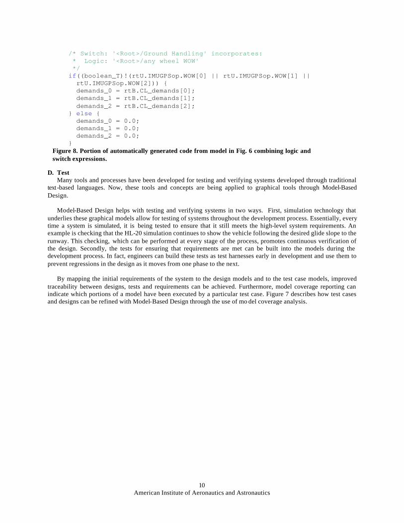
Figure 7 shows the C code that was automatically generated from this algorithm. The code generator was set to preserve the signal no_WOW during optimization. This setting results in readable code and makes is possible to log the no_WOW signal for telemetry or other purposes. In Fig. 8, however, we have set the code generator to optimize the variables as much as possible. This results in the statement for the logical signal and the switch being combined for a more efficient, but less readable, implementation. This is the kind of trade-off that software engineers need to make when using Model-Based Design. Adjusting code generation settings enables software engineers to optimize the code globally for the specific coding standards, guidelines, and hardware constraints of the project.
Figure 6. Portion of guidance flight software, which eliminates control demands when any wheel touches down.
/* Logic: '<Root>/any wheel WOW' */ rtB.no_WOW = (boolean_T)!(rtU.IMUGPSop.WOW[0] || rtU.IMUGPSop.WOW[1] || rtU.IMUGPSop.WOW[2]); /* Switch: '<Root>/Ground Handling' */ if(rtB.no_WOW) { demands_0 = rtB.CL_demands[0]; demands_1 = rtB.CL_demands[1]; demands_2 = rtB.CL_demands[2]; } else { demands_0 = 0.0; demands_1 = 0.0; demands_2 = 0.0; } Figure 7. Portion of automatically generated code from model in Fig. 6 with separate logic and switch expressions.
American Institute of Aeronautics and Astronautics
10
D. Test Many tools and processes have been developed for testing and verifying systems developed through traditional
text -based languages. Now, these tools and concepts are being applied to graphical tools through Model-Based Design.
Model-Based Design helps with testing and verifying systems in two ways. First, simulation technology that
underlies these graphical models allow for testing of systems throughout the development process. Essentially, every time a system is simulated, it is being tested to ensure that it still meets the high-level system requirements. An example is checking that the HL-20 simulation continues to show the vehicle following the desired glide slope to the runway. This checking, which can be performed at every stage of the process, promotes continuous verification of the design. Secondly, the tests for ensuring that requirements are met can be built into the models during the development process. In fact, engineers can build these tests as test harnesses early in development and use them to prevent regressions in the design as it moves from one phase to the next.
By mapping the initial requirements of the system to the design models and to the test case models, improved
traceability between designs, tests and requirements can be achieved. Furthermore, model coverage reporting can indicate which portions of a model have been executed by a particular test case. Figure 7 describes how test cases and designs can be refined with Model-Based Design through the use of mo del coverage analysis.
/* Switch: '<Root>/Ground Handling' incorporates: * Logic: '<Root>/any wheel WOW' */ if((boolean_T)!(rtU.IMUGPSop.WOW[0] || rtU.IMUGPSop.WOW[1] || rtU.IMUGPSop.WOW[2])) { demands_0 = rtB.CL_demands[0]; demands_1 = rtB.CL_demands[1]; demands_2 = rtB.CL_demands[2]; } else { demands_0 = 0.0; demands_1 = 0.0; demands_2 = 0.0; } Figure 8. Portion of automatically generated code from model in Fig. 6 combining logic and switch expressions.

American Institute of Aeronautics and Astronautics
11
V. Conclusion In this paper, we discussed the role of graphical tools in the design of complex systems. A brief review of the
evolution of graphical tools showed that today’s tools provide a unified environment that is both sophisticated and broad enough for mainstream aerospace system development. A sample aerospace design demonstrated how these tools can be effectively leveraged in Model-Based Design, enabling organizations to: ? Foster innovation by conducting rapid design iterations and ‘what-if” studies ? Improve quality by reducing design and hand-coding errors and enabling unambiguous communication among
design teams ? Reduce costs by minimizing the need for expensive prototypes ? Meet schedule milestones mo re effectively
Figure 7. Designs and test cases linked to requirements are part of Model-Based Design applied to aerospace development processes .
American Institute of Aeronautics and Astronautics
12
References
1 Astrom, K. J., Elmquist, H., and Mattsson, S. E., “Evolution of Continuous-Time Modeling and Simulation,” The 12th
European Simulation Multiconference, ESM’98, Manchester, UK, 1998. 2 Erkkinen, T., “Code Generation & High-Integrity Embedded Systems,” Dr. Dobb’s Journal, Vol. 29, Issue 6, June 2004,
pp. 68-70. 3 “HL-20 model for Personnel Launch System research,” NASA Facts on line [online journal], NF172, URL:
http://oea.larc.nasa.gov/PAIS/HL-20.html [cited 12 August 2004], April 1992. 4 MacConochie I. O.,"A Study of Lifting Body as a Space Station Crew Exigency Return Vehicle (CERV)," NASA CR-
2000-210548, October 2000. 5 Jackson E. B., and Cruz C. L.,"Preliminary Subsonic Aerodynamic Model for Simulation Studies of the HL-20 Lifting
Body," NASA TM4302, August 1992. 6 Mosterman, P., and Ghidella, J., “Model Reuse for the Training of Fault Scenarios in Aerospace,” AIAA Modeling and
Simulation Technologies Conference, AIAA-2004-4931, AIAA, Providence, RI, 2004. 7 Krasner, J., “Model-Based Design and Beyond: Solutions for Today’s Embedded Systems Requirements,” Embedded
Market Forecasters, American Technology International, Framingham, MA, January 2004. 8 Hodge, G., Ye, J., and Stuart, W., “Multi-Target Modelling for Embedded Software Development for Automotive
Applications,” 2004 SAE World Congress, 2004-01-0269, SAE International, Detroit, MI, March, 2004.
9 MATLAB, Software Package, Ver. 7.0, The MathWorks, Inc., Natick, MA, 2004.
10 Simulink, Software Package, Ver. 6.0, The MathWorks, Inc., Natick, MA, 2004.
11 Simulink Verification and Validation, Software Package, Ver. 1.0, The MathWorks, Inc., Natick, MA, 2004.
12 Simulink Report Generator, Software Package, Ver. 2.1, The MathWorks, Inc., Natick, MA, 2004.
13 SimMechanics, Software Package, Ver. 2.2, The MathWorks, Inc., Natick, MA, 2004.
14 Stateflow, Software Package, Ver 6.0, The MathWorks, Inc., Natick, MA, 2004.
15 Real-Time Workshop Embedded Coder, Software Package, Ver 4.0, The MathWorks, Inc., Natick, MA, 2004.
16 Aerospace Blockset, Software Package, Ver. 1.6, The MathWorks, Inc., Natick, MA, 2004.