graphical user interface (gui) controlled mobile robot · graphical user interface (gui) controlled...
TRANSCRIPT

Journal of Advanced Research in Computing and Applications
ISSN (online): 2462-1927 | Vol. 1, No. 1. Pages 42-49, 2015
42
Penerbit
Akademia Baru
Graphical User Interface (GUI) Controlled Mobile
Robot
M. H. Zulkefli, K. A. Mohd Annuar*,a, S. H. Joharib, M. R. Mohamad Sapieec and S. Ahmadd
Department of Electrical Engineering Technology, Faculty of Engineering Technology,
Universiti Teknikal Malaysia Melaka, Malaysia a,*[email protected], [email protected], [email protected],
Abstract – The advanced design and development of robotic technology in producing multi task are
increasingly. In this paper presents about designing and developing mobile robot model that can be
controlled using Graphical User Interface (GUI) via wireless protocol. This paper focuses on the
control mobile robot by using the GUI as navigation control and the user can get a view an image and
real time video on visual basic software. To address the problem of sired based control, XBee wireless
communication circuit was used in mobile robot through a computer command. The development of
this mobile robot consists of a chassis, a graphical user interface (GUI), XBee module, DC gear motor,
camera, track wheels and microcontroller type PIC18F4550. Differential driving method using L298
circuit was used to control movement of the robot. In mechanical design, the wheel track has been used
instead of conventional wheels to enable the robot to travel through different types of surfaces or rough
terrain. In addition, wireless cameras was attached to the robot as a system of monitoring function.
Finally, the robot will be designed to control wireless remote control that can control robots. Wireless
remote control allows the user of an environment that is unsafe or dangerous device and evades wires
or cables interfere with the movement of the robot. Copyright © 2015 Penerbit Akademia Baru -
All rights reserved.
Keywords: GUI, Monitoring system, Wireless, Image feedback, Mobile robot
1.0 INTRODUCTION
Nowadays, robotics is not a new field. It has been all over the place for a decade. For example
the car maker uses automated machine to position a car frame, joint a part with spot-weld robot,
bolt piece together, painting and priming. This project is to develop a mobile robot which is
remotely controlled by mean of wireless application. The control is to be done through a
graphical user interface (GUI). The robot must also be capable providing feedback through the
use of electronic device. This project involves hardware and software part. This project has
several applications in surveillance.
Mobile robot design is about art and skill development to create the useful robot for human
application. Each part of mechanical, electrical and software should be studies to make sure
that all mobile robot application can run smoothly and can complete the task given. In
mechanical part, each measurement of the mobile robot design must be details and fixed which
it is important factor to stability and functionality of robot. In electrical and software part also
need research in order to develop a mobile robot that low price, robust and good performance.
Journal of Advanced Research in Computing and Applications
ISSN (online): 2462-1927 | Vol. 1, No. 1. Pages 42-49, 2015
43
Penerbit
Akademia Baru
Abdellatif [1] introduce a mobile service robot with a class of robot and the tools to understand
in order to allow its motion or object conduct in such spaces like the environment at home as
well as office. The development of autonomous mobile robots is give the effect of the
decreasing prices of sensors and computer. Other while to autonomous mobile robots is in
advance much interest of it. Also, to increase the quality of live with the ascending need for
their application in human friendly surroundings.
Using the Fuzzy logic approach in robotics give many positive applications and considered as
an intelligent computational method. Fuzzy Logic Control (FLC) allows the system to hedge
the hesitation from disturbing the control actions. In other method, they propose a method by
via potential field philosophy to integrate the behaviour decisions. It proved be very well-
organized specifically for fast robots. The prototypical of imaging and measurements of aim
position from the colour image, it stated the Tone, Saturation and Intensity, HSI colour space
is used from the time when it is found previously and perceptually constant. Other advantage
is concerning the recognition of object from colour presence in the image is to get better results.
They refer to the design of fuzzy logic controller in authority and the goal is allow the mobile
robot to fulfil two objectives specifically; aim tracking behaviour, obstacle evading behaviour
and else merging both behaviours.
The testing of robot control are use the system structures. In safe and sound controlling the
robot to perceive the object by its colour, it was lead to discover the success of the control
system. Moreover, were lead for separate self-determining behaviours and then for joined
behaviours. A vision-based control system was applied and can enables a mobile robot to
footpath and trail a moving object. Addition, using the potential field theory in the fusion of
behaviour commands was successful in line for to the smooth resolutions from the specific
behaviours.
Li et al., [2] use Wireless Sensor Networks (WSNs) to sense alterations in the surroundings.
Low cost can be expend to large area can be monitored by this network. They have investigated
by “unknown environment” that are intruder detection in a previously, it mean that the
previously unknown to the WSN are the device signatures as well as forms of anomalies. To
confirm if there is an invader in the zone the robot use the camera as an extra sensors. The
important things they try to determine a systematic procedure on this network, so that it can
sensitive only to real anomalies. They must have integrated a machine knowledge system into
the WSN, so the network study to identify usual and unusual approaches of action
automatically. Furthermore, the network can keeps learn from the past and the future of events
without forgetting anything.
They have objectives to achieve in this network as to plan an accessible, well-organized and
tough abnormality recognition system via WSN and other movable robots that will be
positioned in an unidentified surroundings. The features to culture algorithm are first; capable
to notice abnormalities in an unidentified surroundings with least human supervision, second;
capable to straightforwardly scale to enormous numbers of motes, third; capable to care a
hierarchical construction, fourth; computationally inexpensive, fifth; memory efficient, sixth;
capable to identify time-related abnormalities online, seventh; modular, eighth; capable to
endlessly monitor the surroundings, ninth; robust and tenth; able to adopt feedback.
Nevertheless, several clustering systems more appropriate for some precise categories of data
or applications.
In this network, they used architecture for the sensor networks, the fuzzy ART link, and Markov
prototypical extension. On the hardware stages, wireless sensor network contains of two that

Journal of Advanced Research in Computing and Applications
ISSN (online): 2462-1927 | Vol. 1, No. 1. Pages 42-49, 2015
44
Penerbit
Akademia Baru
are fixed sensors (Crossbow motes) and movable robots (Pioneer 3 robots). The results are
from many experiment such as intruder detection system, performance metrics, temporal
change detection experiment and intruder detection experiment. This is the new approach
system from that an invader recognition system by via a wireless sensor network and movable
robots it able in the direction of detect time-related abnormalities.
In the wireless control, they have been achieve of three type wireless control. The first type of
wireless control is the Artemia gesture control by light, second wireless control via magnetic
field for underwater mechanical robot in addition the last is wireless sensor (ZigBee standard).
The mainly targeted requirement of ZigBee are battery-powered applications everywhere small
data rate, small cost and extended battery life. In command to control the gesture of Artemia
populace to arrange three types of gesture patterns that are lining, round as well as zigzag that
used in the wireless underwater robot system. That are proved Artemia group centred on
identifying to transportable light spot and Artemia group be able to be controlled to change in
any direction.
The wireless robot control system is easy to create, small cost and be able to control minor
organism in minor area with execute some patterns like a group of Artemia and which is used
as an instrument to execute a wireless control to citation behaviour of these organisms.
Sahbudin et al., [3] state security is the main issue similar to doors are the central entrance to
our house, company or else whichever sort of building, it suggested a dependable door safety
system be specifically designed. They want to achieve the improvement of a safety system with
linkage capability via microcontroller MOTOROLA MC68HC11A8. Also, to planned on a
market reasonable with a least cost. Moreover, the software part is established segment by
segment because it includes a lot of analysis and correcting. It involve of three part such as a
gathering program, server sideways program and client on the side program. They used the
Eyewatch is primarily to connect with the microcontroller and accomplish database log on
purpose. Winsock programming with Eyewatch that the client side program would
communicate to notify the user about the door situation whether the door is obstructed or not.
The mainly is the analysis actions are concentrated on communication in the middle of
computer as well as the microcontroller. Also, this system uses keypad as an input method.
The experimental design of management program crossing point with microcontroller
MC68HC11A8 as well as extra peripherals such as LCD display, private card magnetic device,
photo device as well as keypad. These peripherals are positioned close to the door. VB are the
core management program contains the subroutines that crossing point with other important
peripherals and the management program will as well act as a server.
Besides that, the management system is planned to observer persons go in or go out from
whichever rooms in a building. In this project it is planned for 4 rooms and supposing consume
only one door. Through GUI interface it also allow user to observer the status of the room door.
The important features included in this security monitoring systems are logoff or logon
program, set timer, door block, set welcome message, check staff login database, check
authorized user database, check unauthorized user database, send email, LAN chat, simulation,
help, about, exit, door database and show time control. There are two types of passwords that
are the password for spending this program and the passwords to admission to the plug-in
database.
VB communication control connects with microcontroller by sending ASCII character.
However, microcontroller consist of send and receive program (assembly language) and

Journal of Advanced Research in Computing and Applications
ISSN (online): 2462-1927 | Vol. 1, No. 1. Pages 42-49, 2015
45
Penerbit
Akademia Baru
hardware. The client plug-in is to be in user’s computer for the determination to notify the user
about the door situation. Hence, a sample door has been created and the system has been
experienced as well. It superbly accomplished the objectives. Also, it suggested the system can
be improved by using wireless application as well as smart card.
In this way, human can tell the robot to change directions, take measurements and so on. For
example, mobile robot can let security personal stay in a central office and still check out
unsupervised areas in a warehouse or other site. This is a new venture that is focused on
intelligent mobile robot that are used in flexible environment and not as automated tool set in
fixed location.
2.0 METHODOLOGY
2.1 Design Concept
Mobile robot design is about art and skill development to create the useful robot for human
application. Each part of mechanical, electrical and software should be studies to make sure
that all mobile robot application can run smoothly and can complete the task given. In
mechanical part, each measurement of the mobile robot design must be details and fixed which
it is important factor to stability and functionality of robot. In electrical and software part also
need research in order to develop a mobile robot that low price, robust and good performance.
Figure 1: Navigation control centre block diagram
Figure 2: Mobile robot block diagram
2.2 Hardware
Mechanical hardware development consists of chassis robot (Perspex), dc gear motor and dc
motor. All this parts perform the important role to the entire operation of mobile robot. Without
good design, model of this mobile robot may not comply with the condition need and not suite
in any robotic application.

Journal of Advanced Research in Computing and Applications
ISSN (online): 2462-1927 | Vol. 1, No. 1. Pages 42-49, 2015
46
Penerbit
Akademia Baru
Figure 3: Mechanical hardware
Electronic hardware development in this project, include circuit model developed in Proteus
software through the training process and then simulation will be done. After simulation phase
is done, PCB can be fabricated to assemble electronic component.
Figure 4: Electronic hardware
2.3 Software
The major software that is used to design this mobile robot is MPLAB compiler, Proteus and
Visual Basic 2010 software. This software are related each other where are used to compile the
coding and to run the simulation. Compile the coding and run the simulation are most important
before applied in the real mobile robot because the error that been occurred in coding and
design easier to trace.
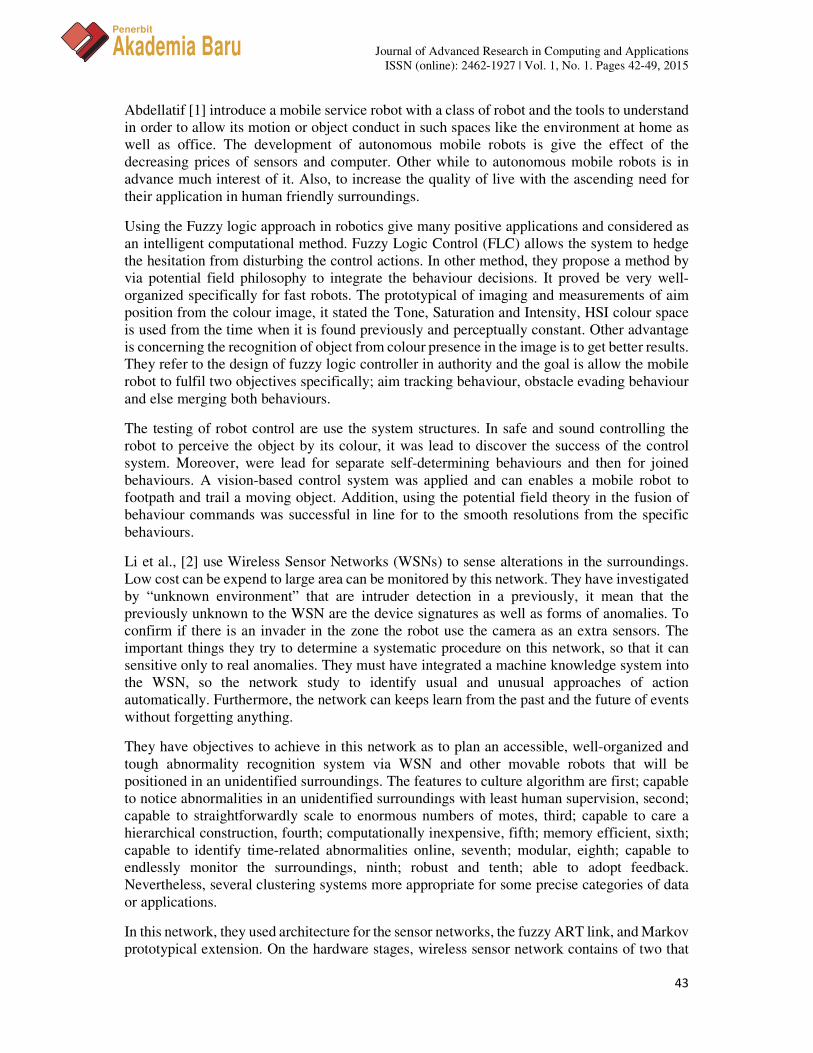
A Graphical User Interface (GUI) is a human-computer interface or simply defined as a way
for humans to interact with computer. There are many programming language that user can
choose to develop a windows application. But through this project will focus on developing
windows application using visual basic programming software.
Microsoft Visual Basic is a form of high level language that help user to create a windows
application easier because it is an object orientated programming. What make Visual Basic
famous around beginner it is drag and drop type of programming with simple coding required.
As any windows application programming, Visual Basic is Event Base Programming. An event
base programming only response when an event is triggered for example, when an event of
clicking a button is occur, then the system will response.
Journal of Advanced Research in Computing and Applications
ISSN (online): 2462-1927 | Vol. 1, No. 1. Pages 42-49, 2015
47
Penerbit
Akademia Baru
Figure 5: GUI design via Microsoft Visual Basic
The microcontroller’s CPU reads program code from memory, one instruction at a time,
decodes each instruction, and then executes it. All memory contents both program code and
data is in binary form strings of 1s and 0s. Instructions are binary codes that tell the CPU what
to do while the data values are the binary (numerical) values that the CPU adds, subtracts,
handles as address values, or otherwise operate on or processes in accordance with the
instructions.
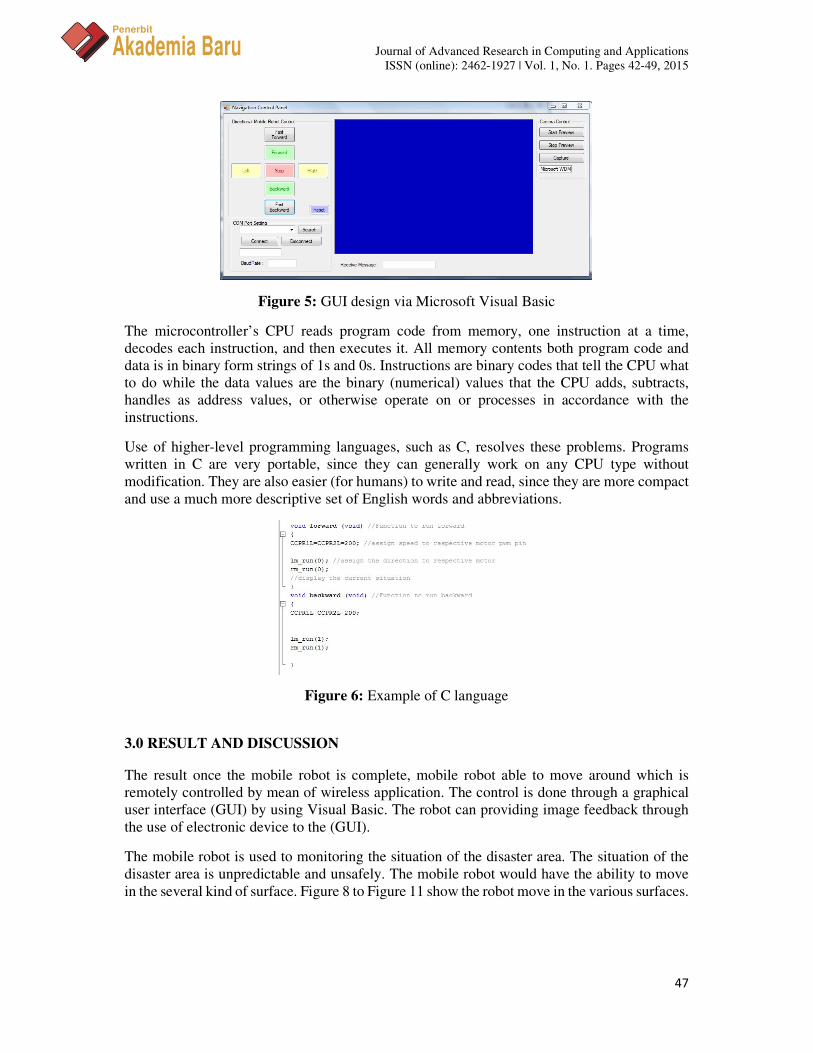
Use of higher-level programming languages, such as C, resolves these problems. Programs
written in C are very portable, since they can generally work on any CPU type without
modification. They are also easier (for humans) to write and read, since they are more compact
and use a much more descriptive set of English words and abbreviations.
Figure 6: Example of C language
3.0 RESULT AND DISCUSSION
The result once the mobile robot is complete, mobile robot able to move around which is
remotely controlled by mean of wireless application. The control is done through a graphical
user interface (GUI) by using Visual Basic. The robot can providing image feedback through
the use of electronic device to the (GUI).
The mobile robot is used to monitoring the situation of the disaster area. The situation of the
disaster area is unpredictable and unsafely. The mobile robot would have the ability to move
in the several kind of surface. Figure 8 to Figure 11 show the robot move in the various surfaces.

Journal of Advanced Research in Computing and Applications
ISSN (online): 2462-1927 | Vol. 1, No. 1. Pages 42-49, 2015
48
Penerbit
Akademia Baru
Figure 7: View of navigation control centre from user
Figure 8: Mobile robot move on dirt
Figure 9: Mobile robot climb sentence high ground
Figure 10: Mobile robot move on grass
Figure 11: Mobile robot move on road
4.0 CONCLUSION
For conclusion, to develop the GUI controlled mobile robot that can perform well, the
mechanical hardware development, electronic hardware development and software

Journal of Advanced Research in Computing and Applications
ISSN (online): 2462-1927 | Vol. 1, No. 1. Pages 42-49, 2015
49
Penerbit
Akademia Baru
development as navigation of robot play an important role. In addition, in realizing the
objective of controlled mobile robot using GUI also give the impact to the making of the robot.
In term of communication between robot and computer the Xbee is use to apply wireless
application. Suggestion from this project is need to upgrading about communication range of
GUI controlled mobile Robot. For this prototype version we use Xbee as a wireless device.
The max range for Xbee wireless device is 100 m on outdoor and 30 m for indoor. But after
we test on full scale application point to point on project the excellent range for experimental
testing is bellow than 20 m. To solve this problem replacing the Xbee WIFI wirelles device.
By using the Xbee WIFI as wireless device development cost will be save and the circuit base
not need to change.
ACKNOWLEDGMENT
The author would like to thank for the support given to this research by Ministry of Higher
Education (MOHE) and University Teknikal Malaysia Melaka (UTeM) for providing a PJP
grant (PJP/2014/FTK(3B)S01302 project), opportunity and necessary facilities to support this
research work.
REFERENCES
[1] M. Abdellatif, A vision-based navigation control system for a mobile service robot, 2007
Annual Conference SICE, IEEE, Takamatsu, 2007, pp. 1517-1522.
[2] Y. Li, L.E. Parker, Detecting and monitoring time-related abnormal events using a
wireless sensor network and mobile robot. International Conference on Intelligent Robots
and Systems (IROS), IEEE, Nice, 2008, pp. 3292-3298.
[3] R.K.Z. Sahbudin, L.C. Hooi, T.C. Guan, L.S. Liet, Room access monitoring system,
Student Conference on Research and Development (SCORED), IEEE, 2003, pp. 304-
308.