grasmannsdorf_workshop - composite simulation - 2013-09-25
TRANSCRIPT

Innovation Intelligence®
Workshop Composite Simulation
Jan Grasmannsdorf
Mittwoch, 25. September 2013
Copyright © 2012 Altair Engineering, Inc. Proprietary and Confidential. All rights reserved.Copyright © 2012 Altair Engineering, Inc. Proprietary and Confidential. All rights reserved.
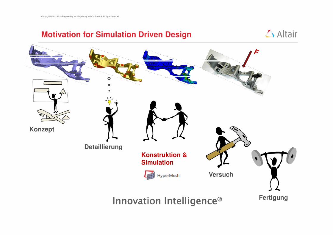
Motivation for Simulation Driven Design
Detaillierung
Fertigung
Konstruktion &
Simulation
Konzept
Versuch
Innovation IntelligenceInnovation IntelligenceInnovation IntelligenceInnovation Intelligence

Copyright © 2012 Altair Engineering, Inc. Proprietary and Confidential. All rights reserved.
Motivation Faserverstärkte Kunststoffe
• Metall hat in alle Richtungen dieselben Eigenschaften
• Struktur daher oft schwerer als benötigt
• Faserverstärkter Kunststoff kann “getunt” werden
• Material / Fasern liegen nur in Lastrichtung
• Großes Leichtbaupotential

Copyright © 2012 Altair Engineering, Inc. Proprietary and Confidential. All rights reserved.
Motivation Faserverstärkte Kunststoffe

Copyright © 2012 Altair Engineering, Inc. Proprietary and Confidential. All rights reserved.Copyright © 2012 Altair Engineering, Inc. Proprietary and Confidential. All rights reserved.
Weitere Optimierungsdisziplinen
Copyright © 2012 Altair Engineering, Inc. Proprietary and Confidential. All rights reserved.
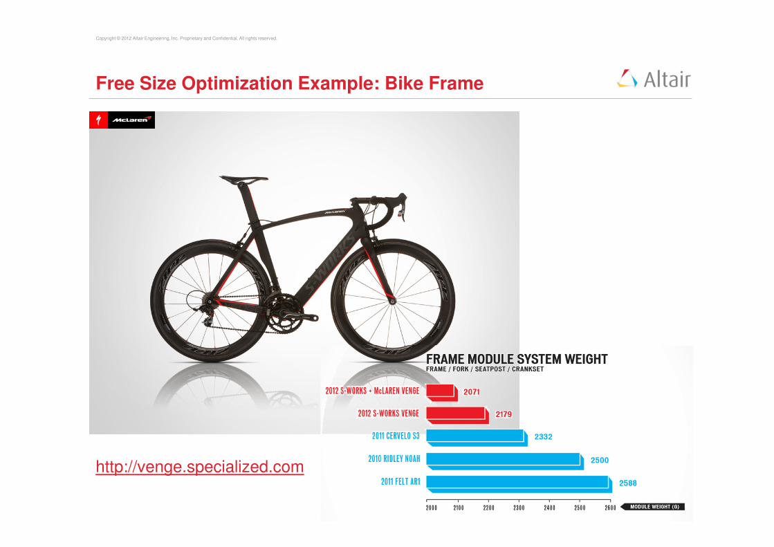
Free Size Optimization Example: Bike Frame
http://venge.specialized.com

Copyright © 2012 Altair Engineering, Inc. Proprietary and Confidential. All rights reserved.Copyright © 2012 Altair Engineering, Inc. Proprietary and Confidential. All rights reserved.
Task: Find the optimum Plybook for a Plate
Fy = - 1000NFix
• Min. Mass
• Displacement
u < 0.6 mm

Copyright © 2012 Altair Engineering, Inc. Proprietary and Confidential. All rights reserved.Copyright © 2012 Altair Engineering, Inc. Proprietary and Confidential. All rights reserved.
Exercise 1: Composite Simulation Setup
• Please note that 2D – Shell Elements are used for this type of simulation
• Define / Review a material orientation (0°°°°layer) for your finite elements
Mesh � Assign � Element Material orientation
• Define / Review the Material Law MAT 8 for orthotropic behaviour
Materials � Create � Card Image MAT 8
• Define / Review the Property for Composite Elementes
Properties � Create � Properties � Card Image PCOMPP
• Define / Review the Ply Shapes for your property
Properties � Create � Plies � Card Image Ply
• Define / Review the Layer Sequence of your plies in a LAMINATE
Properties � Create � Laminates � Card Image STACK
Copyright © 2012 Altair Engineering, Inc. Proprietary and Confidential. All rights reserved.Copyright © 2012 Altair Engineering, Inc. Proprietary and Confidential. All rights reserved.
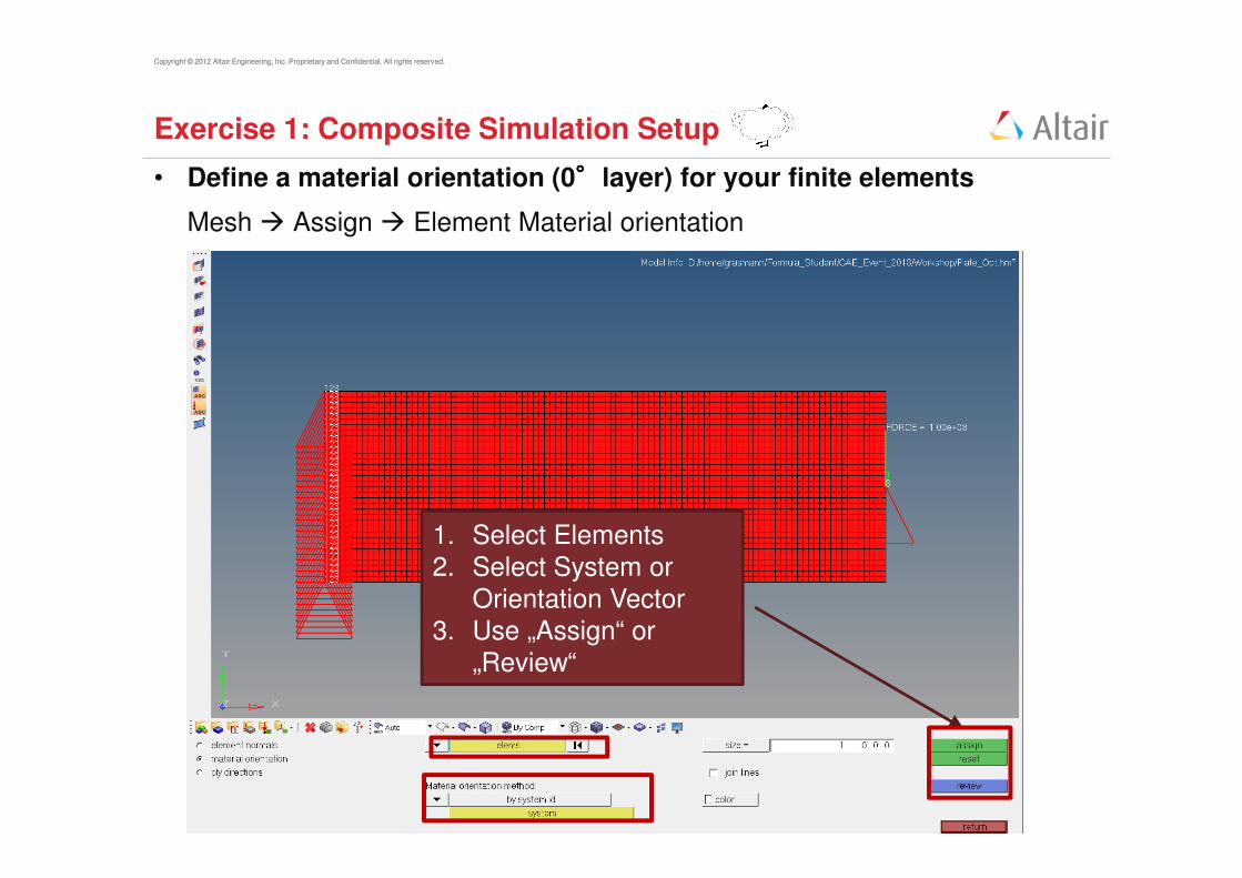
Exercise 1: Composite Simulation Setup
• Define a material orientation (0°°°°layer) for your finite elements
Mesh � Assign � Element Material orientation
1. Select Elements
2. Select System orOrientation Vector
3. Use „Assign“ or
„Review“
Copyright © 2012 Altair Engineering, Inc. Proprietary and Confidential. All rights reserved.Copyright © 2012 Altair Engineering, Inc. Proprietary and Confidential. All rights reserved.
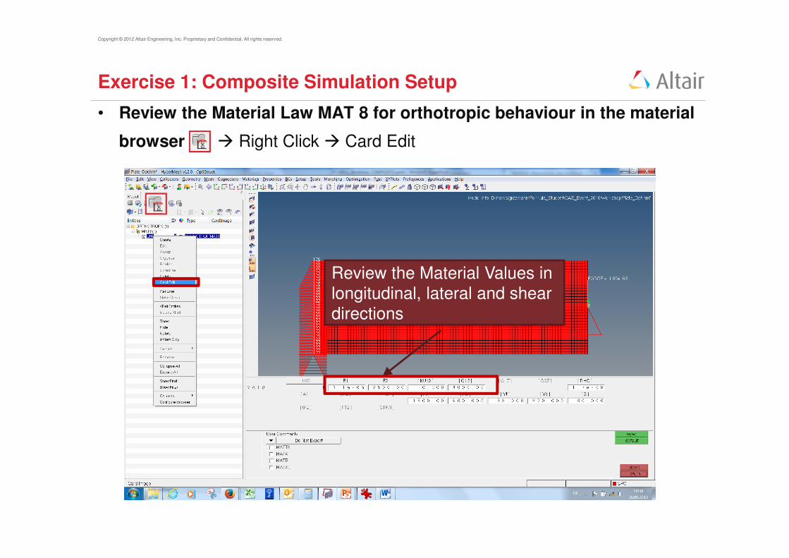
Exercise 1: Composite Simulation Setup
• Review the Material Law MAT 8 for orthotropic behaviour in the material
browser � Right Click � Card Edit
Review the Material Values in
longitudinal, lateral and sheardirections
Copyright © 2012 Altair Engineering, Inc. Proprietary and Confidential. All rights reserved.Copyright © 2012 Altair Engineering, Inc. Proprietary and Confidential. All rights reserved.
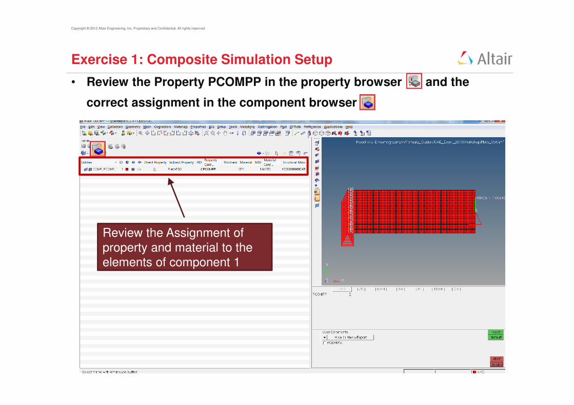
Exercise 1: Composite Simulation Setup
• Review the Property PCOMPP in the property browser and the
correct assignment in the component browser
Review the Assignment of
property and material to the
elements of component 1
Copyright © 2012 Altair Engineering, Inc. Proprietary and Confidential. All rights reserved.Copyright © 2012 Altair Engineering, Inc. Proprietary and Confidential. All rights reserved.
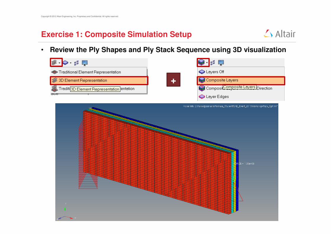
Exercise 1: Composite Simulation Setup
• Review the Ply Shapes and Ply Stack Sequence using 3D visualization
+

Copyright © 2012 Altair Engineering, Inc. Proprietary and Confidential. All rights reserved.Copyright © 2012 Altair Engineering, Inc. Proprietary and Confidential. All rights reserved.
Exercise 1: Composite Simulation Setup
• To re-define plies and laminate sequence, edit the „ply“ and „Laminate“
from the model browser � right click on Ply or Laminate and Edit

Copyright © 2012 Altair Engineering, Inc. Proprietary and Confidential. All rights reserved.Copyright © 2012 Altair Engineering, Inc. Proprietary and Confidential. All rights reserved.
Herausforderung beim Entwurf von Compositebauteilen
Forderung: Beanspruchungsgerechte Bauweise
Werkstoff mit individueller
Gestaltungsmöglichkeit
Viele Freiheitsgrade und
Variationsmöglichkeiten
Wie müssen die Zuschnitte meiner Einzellagen aussehen?
Wie viele Einzellagen des jeweiligen Zuschnittes benötige ich?
In welcher Reihenfolge baue ich mein Laminat auf?
Welche Orientierung benötige ich wo?

Copyright © 2012 Altair Engineering, Inc. Proprietary and Confidential. All rights reserved.
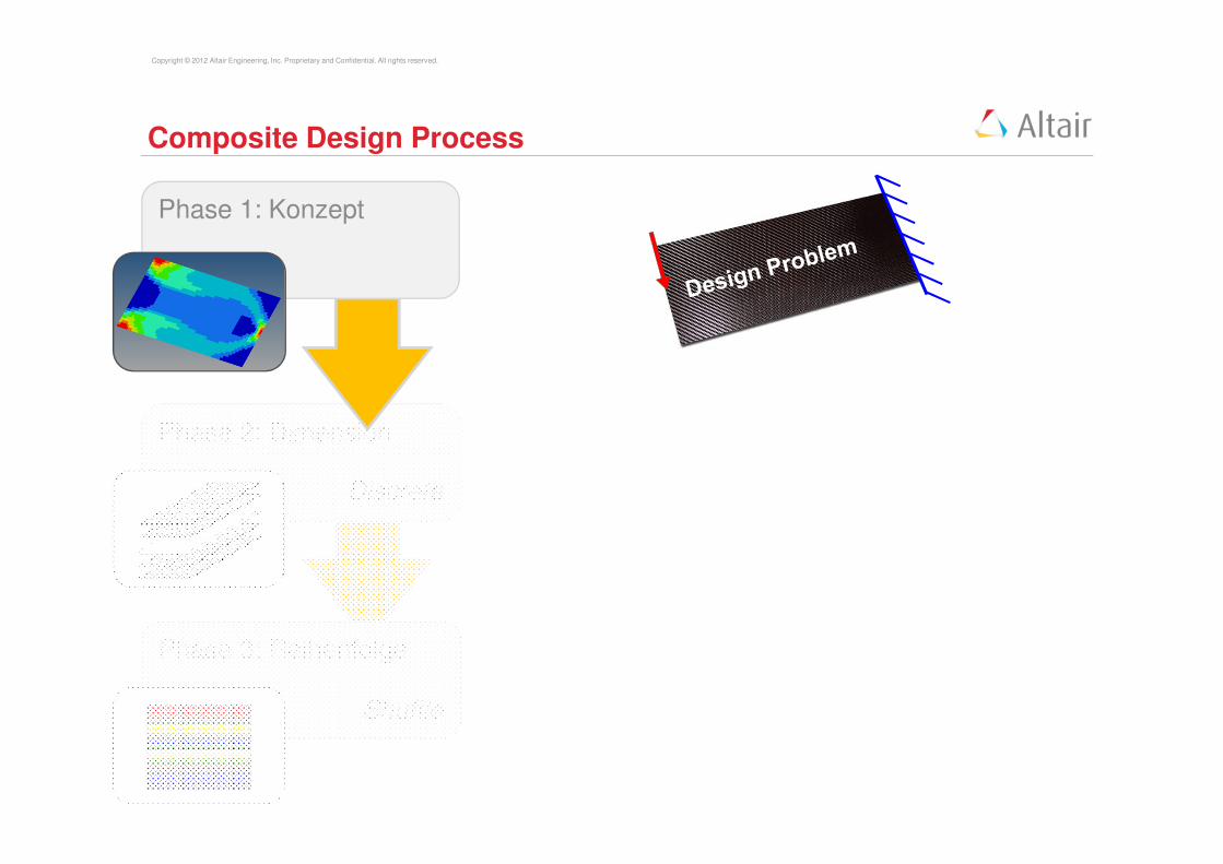
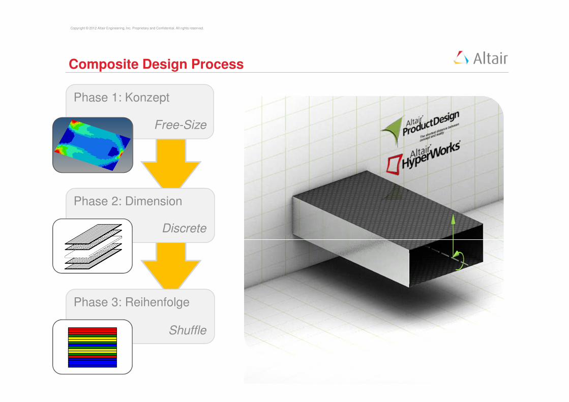
Composite Design Process
Phase 1: Konzept
Welche Faserorientierung wird wo benötigt?
� Free-Size-Optimierung erzeugt eine Dickenverteilung
für jede geplante Faserorientierung.
Diese werden für den Folgeschritt automatisch in
Zuschnitte für die Einzellagen interpretiert.
Phase 1: Konzept
Free-Size
Copyright © 2012 Altair Engineering, Inc. Proprietary and Confidential. All rights reserved.
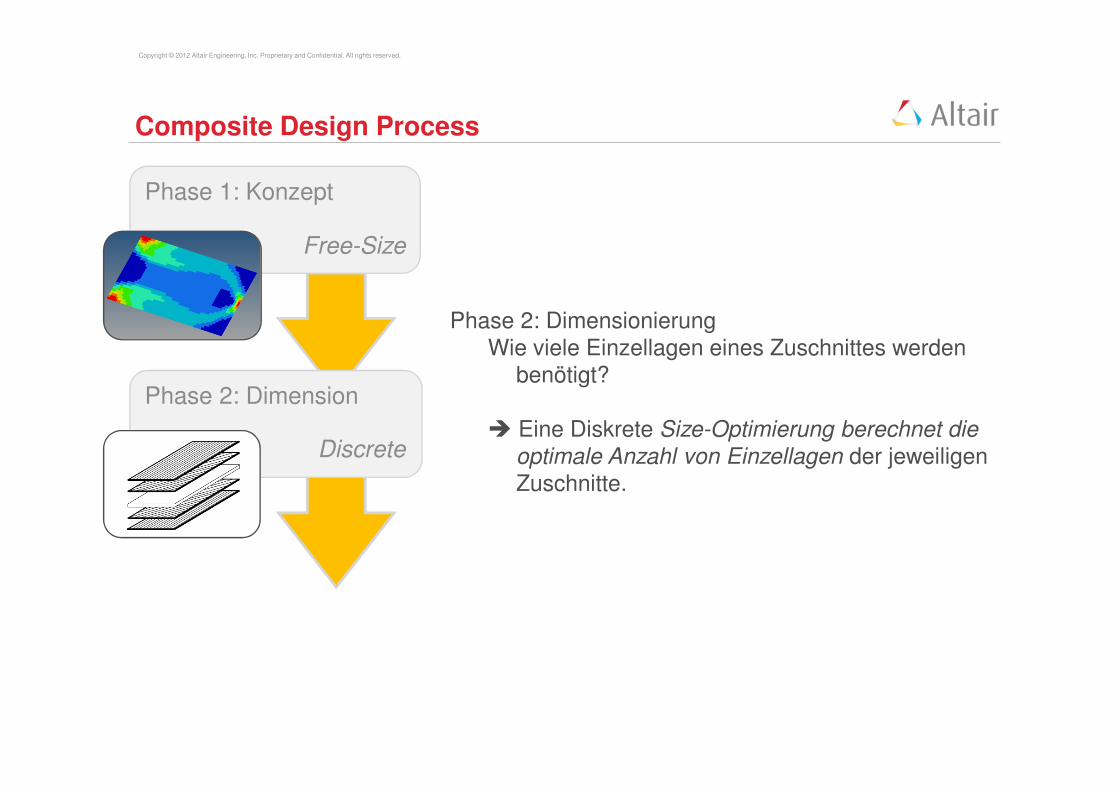
Composite Design Process
Phase 2: DimensionierungWie viele Einzellagen eines Zuschnittes werden
benötigt?
� Eine Diskrete Size-Optimierung berechnet die optimale Anzahl von Einzellagen der jeweiligen Zuschnitte.
Phase 1: Konzept
Free-Size
Phase 2: Dimension
Discrete
Copyright © 2012 Altair Engineering, Inc. Proprietary and Confidential. All rights reserved.
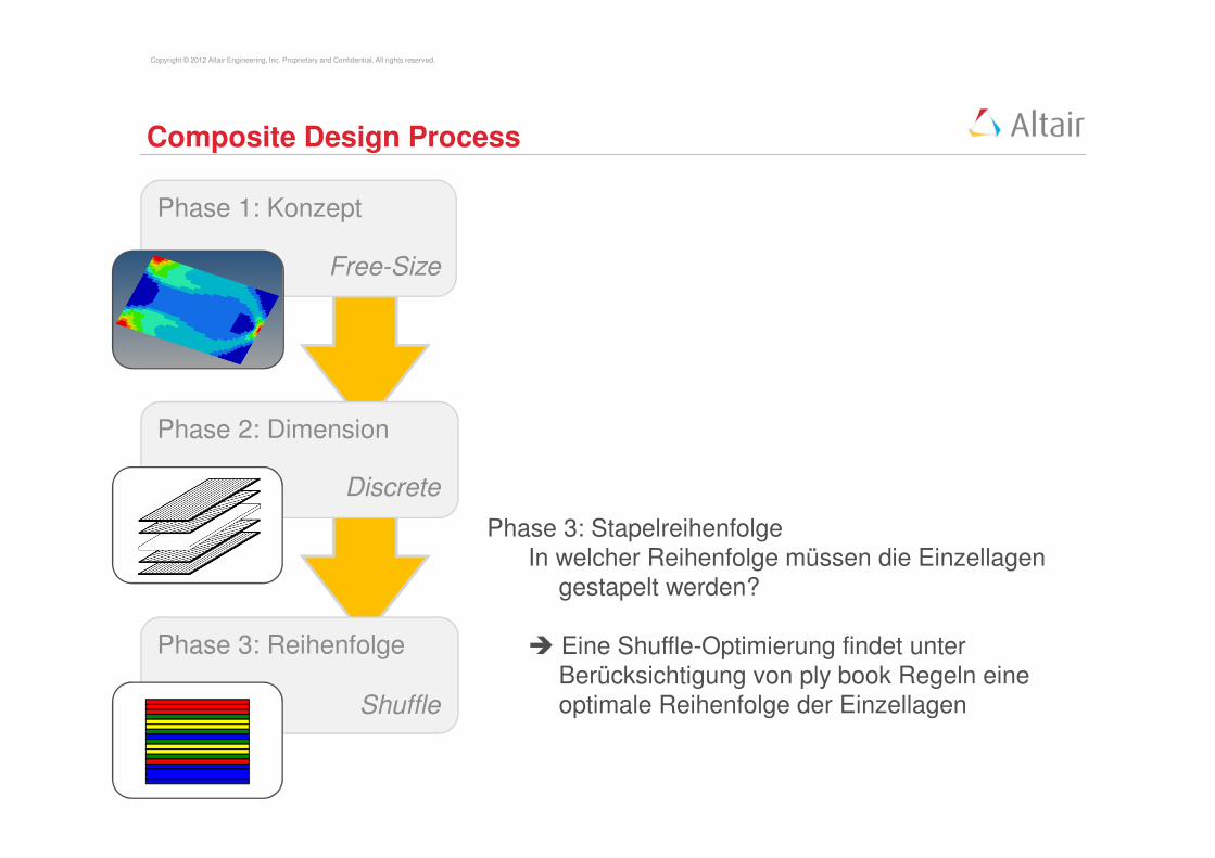
Composite Design Process
Phase 3: StapelreihenfolgeIn welcher Reihenfolge müssen die Einzellagen
gestapelt werden?
� Eine Shuffle-Optimierung findet unter Berücksichtigung von ply book Regeln eine optimale Reihenfolge der Einzellagen
Phase 1: Konzept
Free-Size
Phase 2: Dimension
Discrete
Phase 3: Reihenfolge
Shuffle
Copyright © 2012 Altair Engineering, Inc. Proprietary and Confidential. All rights reserved.
Composite Design Process
Free-Size
Phase 2: Dimension
Discrete
Phase 3: Reihenfolge
Shuffle
Phase 1: Konzept
Copyright © 2012 Altair Engineering, Inc. Proprietary and Confidential. All rights reserved.
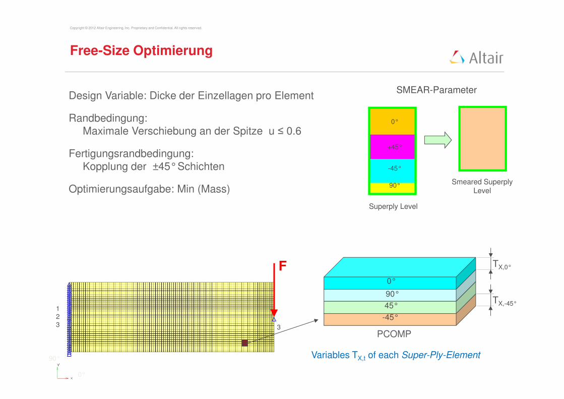
Design Variable: Dicke der Einzellagen pro Element
Randbedingung:
Maximale Verschiebung an der Spitze u ≤ 0.6
Fertigungsrandbedingung:
Kopplung der ±45°Schichten
Optimierungsaufgabe: Min (Mass)
Variables TX,t of each Super-Ply-Element
0°
90°
45°
-45°
PCOMP
TX,-45°
TX,0°F
3
1
2
3
0°
90°
Free-Size Optimierung
SMEAR-Parameter
Smeared Superply Level
Superply Level
0°
+45°
-45°
90°

Copyright © 2012 Altair Engineering, Inc. Proprietary and Confidential. All rights reserved.Copyright © 2012 Altair Engineering, Inc. Proprietary and Confidential. All rights reserved.
Exercise 2: Composite Optimization Setup
• Review the Optimization Entries through the „optimization browser“
• Start the Optimzation Run through Optimization ���� OptiStruct
• Start HyperView and have a look at the results
Review the Optimization
Variable, Objective andConstraints

Copyright © 2012 Altair Engineering, Inc. Proprietary and Confidential. All rights reserved.Copyright © 2012 Altair Engineering, Inc. Proprietary and Confidential. All rights reserved.
Exercise 2: Composite Optimization Setup
• Create a new HyperMesh Session and read „plate_opt_sizing.10.fem“
through File � Import � Solver Deck
Review the optimized ply
shapes

Copyright © 2012 Altair Engineering, Inc. Proprietary and Confidential. All rights reserved.
Total element thickness distribution T0 + T90 + T-45 + T45
0°
90°
45°
-45°
PCOMP
T-45°
T0°
Free-Size Optimization
Copyright © 2012 Altair Engineering, Inc. Proprietary and Confidential. All rights reserved.
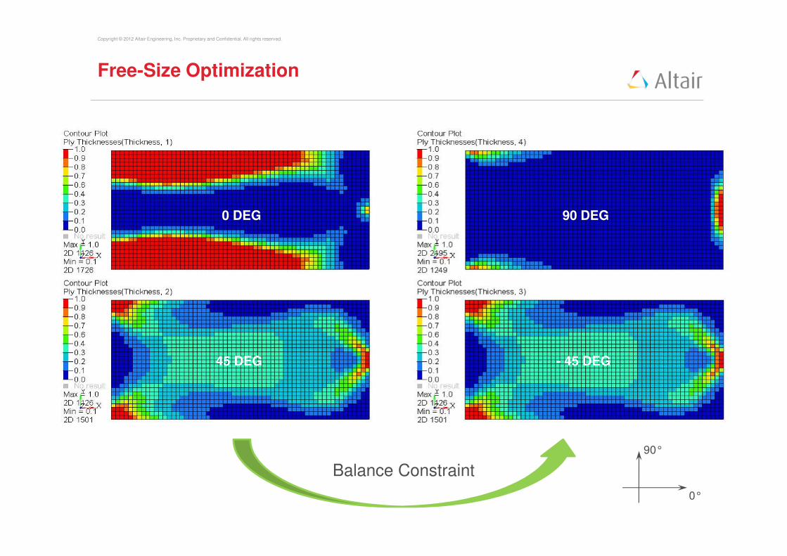
Balance Constraint
0°
90°
0 DEG
- 45 DEG45 DEG
90 DEG
Free-Size Optimization

Copyright © 2012 Altair Engineering, Inc. Proprietary and Confidential. All rights reserved.
0°
-45°45°
90°
0 DEG 90 DEG
- 45 DEG45 DEG
• Automatic extraction of patches from free-sizing optimization
• User defined number of patches per ply orientation
• Tune manufacturing complexity
Example: 4 patches
Free-Size Optimization

Copyright © 2012 Altair Engineering, Inc. Proprietary and Confidential. All rights reserved.
Discrete Size optimization
Phase 1: Konzept
Free-Size
Discrete
Phase 3: Reihenfolge
Shuffle
Phase 2: Dimension
Copyright © 2012 Altair Engineering, Inc. Proprietary and Confidential. All rights reserved.
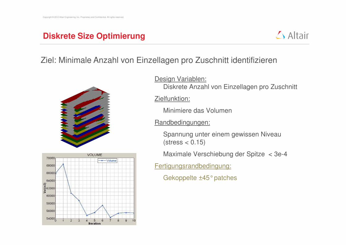
Ziel: Minimale Anzahl von Einzellagen pro Zuschnitt identifizieren
Design Variablen:
Diskrete Anzahl von Einzellagen pro Zuschnitt
Zielfunktion:
Minimiere das Volumen
Randbedingungen:
Spannung unter einem gewissen Niveau
(stress < 0.15)
Maximale Verschiebung der Spitze < 3e-4
Fertigungsrandbedingung:
Gekoppelte ±45°patches
Diskrete Size Optimierung
Copyright © 2012 Altair Engineering, Inc. Proprietary and Confidential. All rights reserved.
Shuffling Optimierung
Phase 1: Konzept
Free-Size
Phase 2: Dimension
Discrete
Phase 3: Reihenfolge
Shuffle

Copyright © 2012 Altair Engineering, Inc. Proprietary and Confidential. All rights reserved.
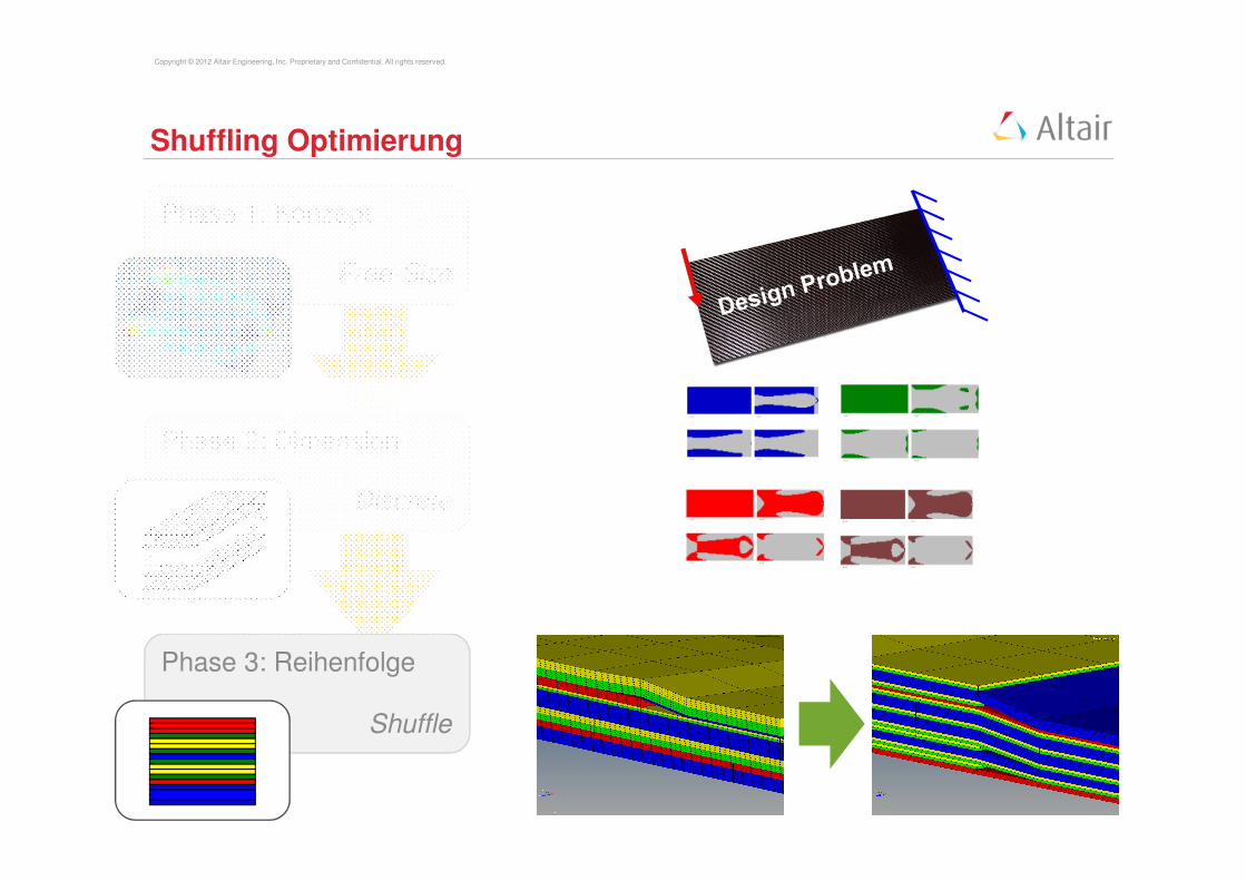
Shuffling Optimierung
Ziel: den Plybook Regeln entsprechen mit Design undFertigungsrandbedingungen
+45
-45 0 0 0
+45
-45
+45
-45 0 0 0
+45
-4500
0
45
-45
90
45 -45 0 0
45 -45 90
90 -45 45 0 0
-45 45
Beispiel: maximale Anzahl aufeinander folgender Lagen mit gleichemFaserwinkel (typisch 3 oder 4)
Kern- und DecklagendefinitionPly pairing...
Copyright © 2012 Altair Engineering, Inc. Proprietary and Confidential. All rights reserved.
Composite Design Process
Phase 1: Konzept
Free-Size
Phase 2: Dimension
Discrete
Phase 3: Reihenfolge
Shuffle

Copyright © 2012 Altair Engineering, Inc. Proprietary and Confidential. All rights reserved.
Fazit
Leichtbaustrukturen erfordern Beanspruchungsgerechtes Designs!
Altairs Composite Design Prozess stellt sicher dass:
- beanspruchungsgerechte Designs erzielt werden
- die Komplexität des Werkstoffes beherrschbar wird
- manuelle Iterationen eingespart werden
- die Auslegung von Faserverbundstrukturen
sicherer und schneller wird
… hilft das wahre Leichtbaupotential von Laminatstrukturen zu heben!
Copyright © 2012 Altair Engineering, Inc. Proprietary and Confidential. All rights reserved.
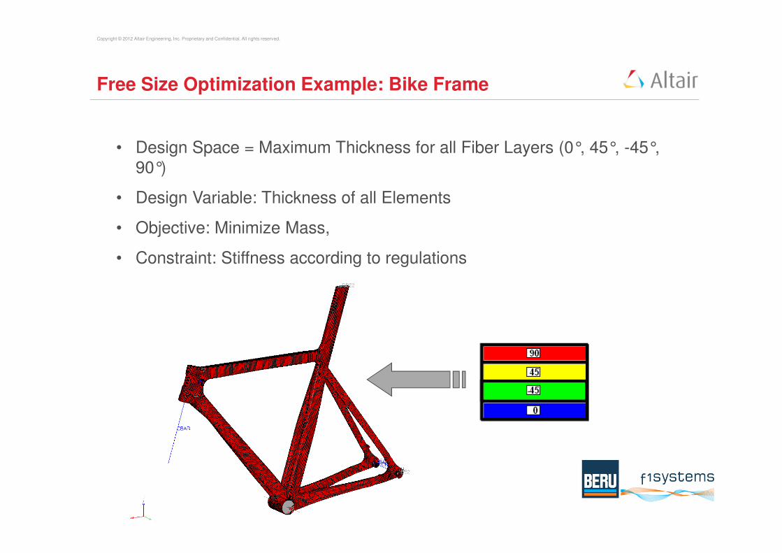
Free Size Optimization Example: Bike Frame
• Design Space = Maximum Thickness for all Fiber Layers (0°, 45°, -45°, 90°)
• Design Variable: Thickness of all Elements
• Objective: Minimize Mass,
• Constraint: Stiffness according to regulations

Copyright © 2012 Altair Engineering, Inc. Proprietary and Confidential. All rights reserved.
Free Size Optimization Example: Bike Frame
• Thickness Results for all Composite FibreLayers
• The Layer at 0°needs the most
material
0° +45°
- 45° +90°

Copyright © 2012 Altair Engineering, Inc. Proprietary and Confidential. All rights reserved.
Free Size Optimization Example: Bike Frame
• Design Interpretation and further optimization leads to 12 Composite Patches
• All regulations were met with this lightweight frame
Patch 1
Patch 2