gravity fed system team members: james brinkerhoff, christopher kulbago, patrick o’connell, lauren...
TRANSCRIPT

Gravity Fed SystemTeam Members: James Brinkerhoff, Christopher Kulbago, Patrick O’Connell, Lauren Pahls, Ted Rakiewicz, Sarah Salmon Group Number: P13631
1

Table of Contents1. Team Roles2. Project Background3. Schedule MSD II4. High Level Customer Needs5. Budget and Costs6. Bill of Materials7. Engineering Specifications8. Concept Generation9. Feasibility Analysis10. Original System Architecture11. Original P&ID12. Original Cart Layout13. MSD I vs. MSD II Comparison14. Final P&ID15. Final Cart Layout16. Test Results Data17. Labview Layout18. Risk Assessment19. Successes and Failures20. Issues and Actions MSD I21. Issues and Actions MSD II22. Questions
2
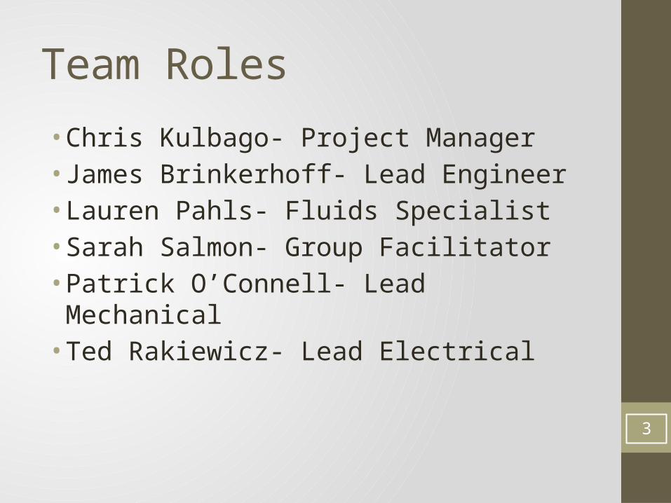
Team Roles
• Chris Kulbago- Project Manager• James Brinkerhoff- Lead Engineer• Lauren Pahls- Fluids Specialist• Sarah Salmon- Group Facilitator• Patrick O’Connell- Lead Mechanical• Ted Rakiewicz- Lead Electrical
3
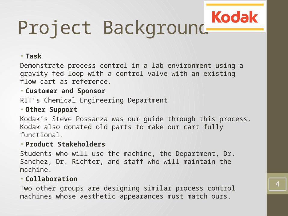
Project Background• TaskDemonstrate process control in a lab environment using a gravity fed loop with a control valve with an existing flow cart as reference.• Customer and SponsorRIT’s Chemical Engineering Department• Other SupportKodak’s Steve Possanza was our guide through this process. Kodak also donated old parts to make our cart fully functional.• Product StakeholdersStudents who will use the machine, the Department, Dr. Sanchez, Dr. Richter, and staff who will maintain the machine.• CollaborationTwo other groups are designing similar process control machines whose aesthetic appearances must match ours.
4
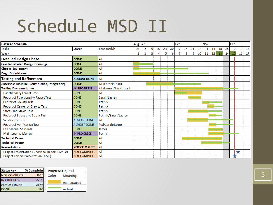
Schedule MSD II
5

Customer Needs• Did we meet them?
Customer need: Does project fulfill need?
Safety Yes
Ergonomics Yes
Mobility Yes
Teaching Manually Yes
Teaching Auto-Controls Yes
Ease of Assembly Yes
Low Cost Yes
Use of LabVIEW Yes
Drained Tank Dynamics Yes 6

High Level Customer Needs• Machine Design Needs:• A way for students to manually manipulate flow. • A way to manually measure flow. • Easily operated by 3 students.• A safely operating machine.• Interface of machine with LabVIEW.• A way to demonstrate main concepts of process control.• A way to demonstrate noise and time lag in sensors.
• Student Learning Needs:• A lab manual that guides students through lab in a way that
engenders learning. • Discussion questions within lab manual that test understanding
of process control. • Lab manual that focuses on PID control, noise, filtration, data
modeling, disturbances, and/or hysteresis.
7

Budget & Costs
0
200
400
600
800
1000
1200
1400
1600
1086.74
1206.28
1500
Budget Tracking
Actual SpentAnticipated SpendingOriginal Request
Mon
ey ($
)
8
Bill of Materials
9
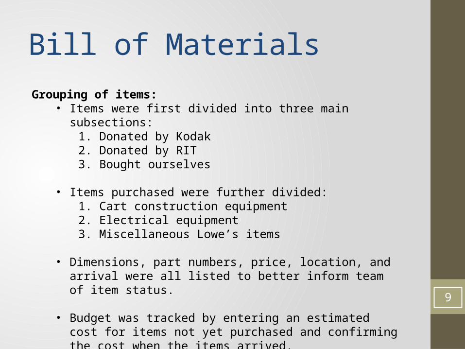
Grouping of items:• Items were first divided into three main subsections:
1. Donated by Kodak2. Donated by RIT3. Bought ourselves
• Items purchased were further divided:1. Cart construction equipment2. Electrical equipment3. Miscellaneous Lowe’s items
• Dimensions, part numbers, price, location, and arrival were all listed to better inform team of item status.
• Budget was tracked by entering an estimated cost for items not yet purchased and confirming the cost when the items arrived.
• Our bill of materials is very large and can be viewed on our Edge site.
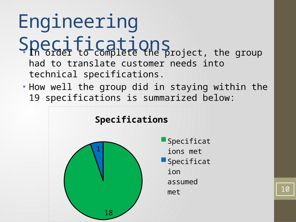
Engineering Specifications• In order to complete the project, the group had to translate
customer needs into technical specifications.• How well the group did in staying within the 19 specifications is
summarized below:
18
1
Specifications
Specifications met
Specification assumed met
Specification not met 10

Specifications Met: Part 1
11

Specifications Met: Part 2
12

Specifications Met: Part 3
13

Specification Assumed Met
14

Contingency Plan for Assumed Specification
• Contact 4th year Chemical Engineering students to test cart.• Conduct time and operation trials on all contacted persons with cart
and lab manual.
15

Concept Generation
16

Feasibility Analysis• Line pressure confirmation• With one faucet received around 50 psi• With all faucets on decreased to about 45 psi
17
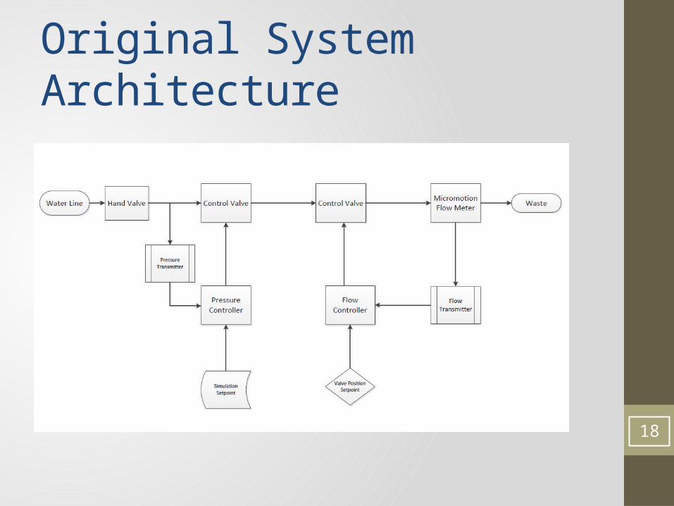
Original System Architecture
18
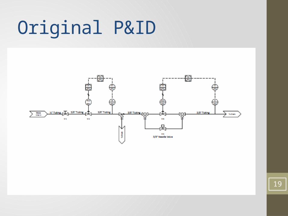
Original P&ID
19
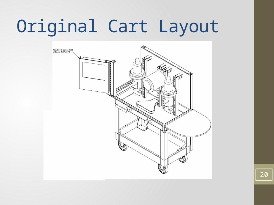
Original Cart Layout
20

MSD I vs. MSD II ComparisonItem MSD I MSD II
Overall goal Concept Generation Building and Integration
Deliverables Theoretical; Organization and charts
As-built final documents
Time 10 weeks 16 weeks
Individual Contributions About equal More work from EE and ME
Grading Throughout; Several milestones
Only a Functional Review and a Final Review
21

Final P&ID
22
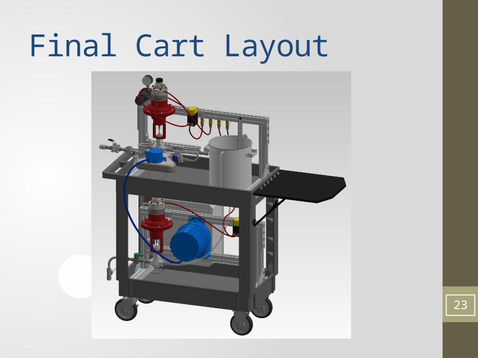
Final Cart Layout
23

Test Results Data
24
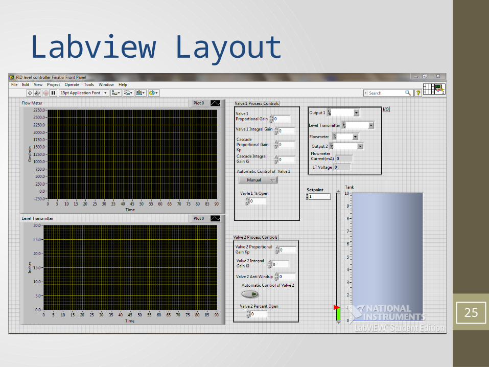
Labview Layout
25

Risk Assessment
26

Successes & Failures• Successes• Cart is aesthetically constructed, and highly functional.• LabVIEW provides accurate data collection and adequately allows
for student interaction for real-time process control of a dynamic system.
• Group overcame an equipment failure, and adapted to prevent project hindrance.
• Project is under budget.• All deliverables submitted on time.
• Failures• Digital-to-Analog Converter operation is deviated from design
intent (as of right now).• Cart water usage is not optimized. 27
Issues/Actions MSD I• Gravity fed to line feed• We initially were going to have a project that was “gravity fed to a
line feed,” where we had a permanent height for a gravity feed stream.
• Instead of this, we decided to use a second control loop and set of code in order to be able to be more versatile and mimic different heights with different water pressures from a water line.
• Coordinating cart purchase• We discussed a cart design that fits the needs of all three groups.• After negotiating, we came up with a final cart to be used by all
three groups.• Slow start to project• Edge was not readily available for students at the start of MSD I.• The lab learning portion was in progress
28

Issues/Actions MSD II• Misinterpreted Pressure Loss• Water pressure loss across flow tube was greater than calculated, and therefore
the water flow rate out in preliminary testing was too low.• We rearranged the cart layout to use potential energy to make our cart drain at
the required flow rate.
• Delicate Level Transmitter• The original mounting design for the level transmitter damaged it. After
mounting, it gave erroneous readings.• A new level transmitter was rush delivered and mounted with electrical tape.
Special handling instructions were noted in manual.
• Interface Issues• The equipment given to us by Kodak was very used and worn. At first, we did
not know how to properly control the 2 I/P circuits, preventing control valve operation.
• Through rigorous testing, this problem was solved and our I/P’s are now fully functional as anticipated.
29

Future Suggestions• Recycle Loop• Install a pump with a recycle stream and an additional tank or vessel in
order to reduce water usage.• Time Study• Have 4th year Chemical Engineering students perform the lab procedure
and measure time it takes for students to complete the lab.• Switch Microcontroller• Replace the msp430 Microcontroller with a more reliable National
Instruments Data Acquisition for increased accuracy, ease of assembly and use.
• Newer and More Robust Parts• The Level Transmitter we purchased was low in cost but carries a risk. A
differential pressure cell would minimize this risk.• Parts donated by Kodak are used and worn, and if these are replaced the
robustness of the cart can improve.
30

Questions?
31