green building design - taco - hvac · primary-secondary pumping. the new technology consists of...
TRANSCRIPT
green
R E A L W O R L D H Y D R O N I C S Y S T E M T E C H N O L O G Y
buildingdesign
Taco LoadMatch® Real world hydronic system technology for Green Building design.
LoadMatch®
System.
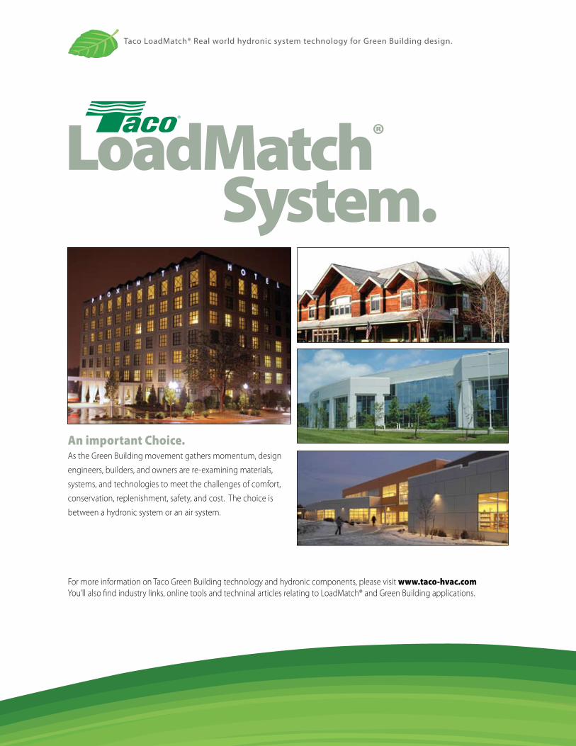
An important Choice.As the Green Building movement gathers momentum, design
engineers, builders, and owners are re-examining materials,
systems, and technologies to meet the challenges of comfort,
conservation, replenishment, safety, and cost. The choice is
between a hydronic system or an air system.
For more information on Taco Green Building technology and hydronic components, please visit www.taco-hvac.comYou’ll also find industry links, online tools and techninal articles relating to LoadMatch® and Green Building applications.
Taco LoadMatch® Real world hydronic system technology for Green Building design.
Hydronic Systems Save Energy And Materials.Both kinds of HVAC systems impact
the environment in two ways: 1) Each
consumes non-regenerative raw materi-
als in construction. 2) Each consumes
energy to operate. Again, hydronic sys-
tems win. Advanced LoadMatch® single
pipe hydronic systems require less raw
materials for construction by virtue of
a reduction in pipe, fittings, insulation,
control valves, and balancing valves. To
move BTUs around a building, hydronic
systems require about half the energy
of a comparable air system, because
water has a higher specific heat and
higher density than air.
Hydronic Systems Are More Comfortable.Because of the higher thermal inertia
of water, the temperature in a room
heated or cooled by hydronics will be
more even and thus more comfortable.
Additionally, when the room is heated
or cooled by a LoadMatch® single pipe
system, the temperature will be more
consistent and, therefore, even more
comfortable. A LoadMatch® system is
self balancing; tweaking balance valves
to get the water to the right location in
the right quantity isn’t necessary.
Hydronic Systems Are Healthier.Airborne contaminants are a constant
concern to building dwellers and own-
ers alike. Because a hydronic system is
a sealed system, molds, viruses, pollen,
dust, and bacteria can’t be blown
around the building.
The Taco LoadMatch® System: Next Generation Hydronics For Green Building Design.Essentially, the LoadMatch® single pipe
system replaces all the expensive and
energy-consuming control valves and
most balancing valves with small, low
kW circulators. The circulators HELP
deliver the water to where it needs to
go, as opposed to FORCING the water
to go where it doesn’t want to. The
savings in raw material, installation
costs, and energy consumption are
substantial.
LoadMatch® Means Better Comfort.Because a LoadMatch® system is self
balancing, consistent temperature
delivers better comfort. All loads oper-
ate separately from one another. The
secondary flow that circulates through
each terminal is independent of the
system’s primary distribution pumps.
LoadMatch® Saves More EnergyIn addition to the energy savings
inherent in hydronic systems, Load-
Match® eliminates head loss by elimi-
nating control valves, balance valves,
and some pipe (when compared to a
conventional reverse return system).
The result is lower pump head and
less energy consumption to move the
water.
Taco LoadMatch® Real world hydronic system technology for Green Building design.
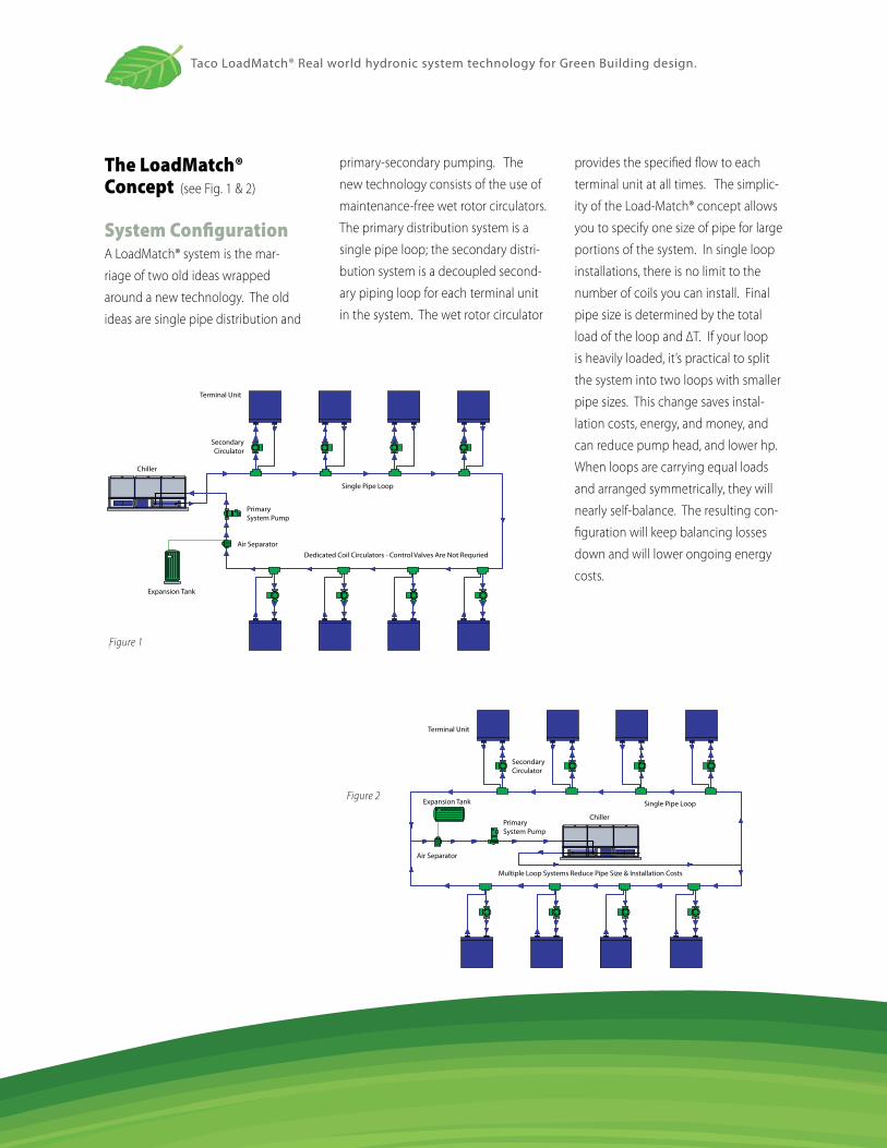
The LoadMatch® Concept (see Fig. 1 & 2)
System ConfigurationA LoadMatch® system is the mar-
riage of two old ideas wrapped
around a new technology. The old
ideas are single pipe distribution and
primary-secondary pumping. The
new technology consists of the use of
maintenance-free wet rotor circulators.
The primary distribution system is a
single pipe loop; the secondary distri-
bution system is a decoupled second-
ary piping loop for each terminal unit
in the system. The wet rotor circulator
provides the specified flow to each
terminal unit at all times. The simplic-
ity of the Load-Match® concept allows
you to specify one size of pipe for large
portions of the system. In single loop
installations, there is no limit to the
number of coils you can install. Final
pipe size is determined by the total
load of the loop and ∆T. If your loop
is heavily loaded, it’s practical to split
the system into two loops with smaller
pipe sizes. This change saves instal-
lation costs, energy, and money, and
can reduce pump head, and lower hp.
When loops are carrying equal loads
and arranged symmetrically, they will
nearly self-balance. The resulting con-
figuration will keep balancing losses
down and will lower ongoing energy
costs.
FIGURE 1
Terminal Unit
SecondaryCirculator
Expansion Tank
PrimarySystem Pump
Chiller
Single Pipe Loop
Air SeparatorDedicated Coil Circulators - Control Valves Are Not Requried
Figure 1
FIGURE 2
Terminal Unit
SecondaryCirculator
Expansion Tank
PrimarySystem Pump
Chiller
Single Pipe Loop
Air Separator
Multiple Loop Systems Reduce Pipe Size & Installation Costs
Figure 2
Taco LoadMatch® Real world hydronic system technology for Green Building design.
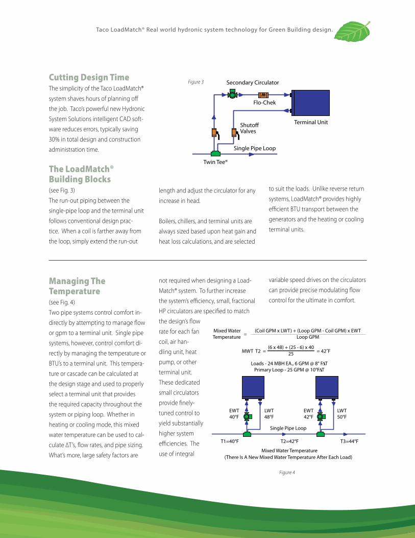
Cutting Design TimeThe simplicity of the Taco LoadMatch®
system shaves hours of planning off
the job. Taco’s powerful new Hydronic
System Solutions intelligent CAD soft-
ware reduces errors, typically saving
30% in total design and construction
administration time.
The LoadMatch® Building Blocks
(see Fig. 3)
The run-out piping between the
single-pipe loop and the terminal unit
follows conventional design prac-
tice. When a coil is farther away from
the loop, simply extend the run-out
Secondary Circulator
Flo-Chek
Terminal UnitShutoffValves
Twin Tee®
Single Pipe Loop
FIGURE 3Figure 3
length and adjust the circulator for any
increase in head.
Boilers, chillers, and terminal units are
always sized based upon heat gain and
heat loss calculations, and are selected
to suit the loads. Unlike reverse return
systems, LoadMatch® provides highly
efficient BTU transport between the
generators and the heating or cooling
terminal units.
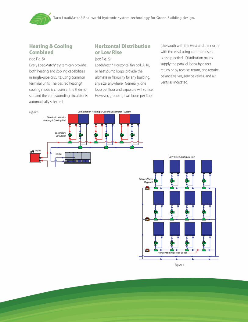
Managing The Temperature (see Fig. 4)
Two pipe systems control comfort in-
directly by attempting to manage flow
or gpm to a terminal unit. Single pipe
systems, however, control comfort di-
rectly by managing the temperature or
BTU’s to a terminal unit. This tempera-
ture or cascade can be calculated at
the design stage and used to properly
select a terminal unit that provides
the required capacity throughout the
system or piping loop. Whether in
heating or cooling mode, this mixed
water temperature can be used to cal-
culate ∆T’s, flow rates, and pipe sizing.
What’s more, large safety factors are
not required when designing a Load-
Match® system. To further increase
the system’s efficiency, small, fractional
HP circulators are specified to match
the design’s flow
rate for each fan
coil, air han-
dling unit, heat
pump, or other
terminal unit.
These dedicated
small circulators
provide finely-
tuned control to
yield substantially
higher system
efficiencies. The
use of integral
variable speed drives on the circulators
can provide precise modulating flow
control for the ultimate in comfort.
Single Pipe Loop
Mixed WaterTemperature
(Coil GPM x LWT) + (Loop GPM - Coil GPM) x EWTLoop GPM
Loads - 24 MBH EA., 6 GPM @ 8° F TPrimary Loop - 25 GPM @ 10°F T
EWT40°F
LWT48°F
EWT42°F
LWT50°F
T1=40°F T2=42°F T3=44°F
Mixed Water Temperature(There Is A New Mixed Water Temperature After Each Load)
MWT T2 = = 42˚F(6 x 48) + (25 - 6) x 40
25
Figure 4
Taco LoadMatch® Real world hydronic system technology for Green Building design.
Heating & Cooling Combined (see Fig. 5)
Every LoadMatch® system can provide
both heating and cooling capabilities
in single-pipe circuits, using common
terminal units. The desired heating/
cooling mode is chosen at the thermo-
stat and the corresponding circulator is
automatically selected.
Horizontal Distribution or Low Rise (see Fig. 6)
LoadMatch® Horizontal fan coil, AHU,
or heat pump loops provide the
ultimate in flexibility for any building,
any size, anywhere. Generally, one
loop per floor and exposure will suffice.
However, grouping two loops per floor
(the south with the west and the north
with the east) using common risers
is also practical. Distribution mains
supply the parallel loops by direct
return or by reverse-return, and require
balance valves, service valves, and air
vents as indicated.
Balance Valve(Typical)
Horizontal Single Pipe Loops
Low Rise Configuration
FIGURE 5 Combination Heating & Cooling LoadMatch® System
Terminal Unit withHeating & Cooling Coil
SecondaryCirculator
BoilerChiller
Figure 5
Figure 6
Taco LoadMatch® Real world hydronic system technology for Green Building design.
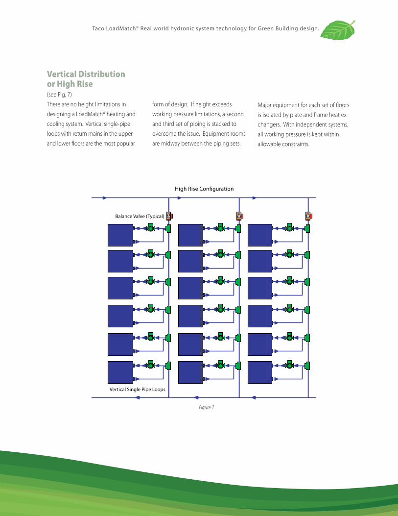
Vertical Distribution or High Rise
(see Fig. 7)
There are no height limitations in
designing a LoadMatch® heating and
cooling system. Vertical single-pipe
loops with return mains in the upper
and lower floors are the most popular
form of design. If height exceeds
working pressure limitations, a second
and third set of piping is stacked to
overcome the issue. Equipment rooms
are midway between the piping sets.
Major equipment for each set of floors
is isolated by plate and frame heat ex-
changers. With independent systems,
all working pressure is kept within
allowable constraints.
High Rise Configuration
Vertical Single Pipe Loops
FIGURE 7
Balance Valve (Typical)
Figure 7
Taco LoadMatch® Real world hydronic system technology for Green Building design.
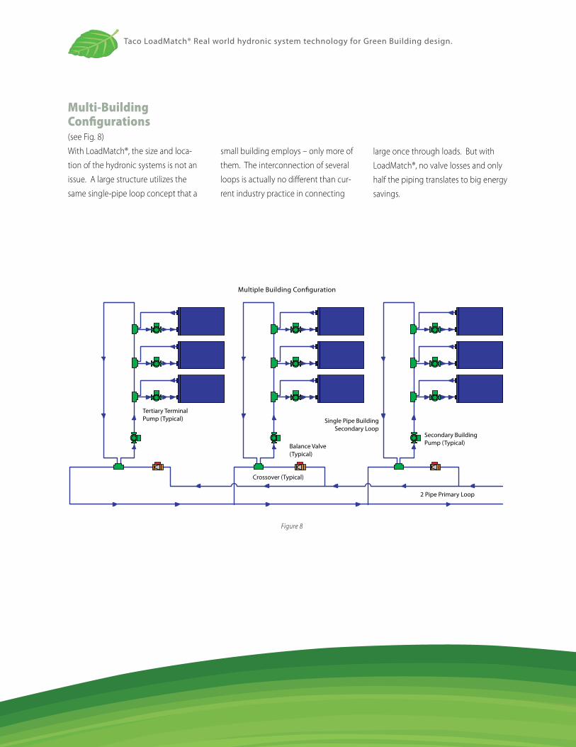
Multi-Building Configurations
(see Fig. 8)
With LoadMatch®, the size and loca-
tion of the hydronic systems is not an
issue. A large structure utilizes the
same single-pipe loop concept that a
small building employs – only more of
them. The interconnection of several
loops is actually no different than cur-
rent industry practice in connecting
large once through loads. But with
LoadMatch®, no valve losses and only
half the piping translates to big energy
savings.
Tertiary TerminalPump (Typical)
FIGURE 8
Balance Valve(Typical)
Crossover (Typical)
Secondary BuildingPump (Typical)
Single Pipe BuildingSecondary Loop
2 Pipe Primary Loop
Multiple Building Configuration
Figure 8
Taco LoadMatch® Real world hydronic system technology for Green Building design.
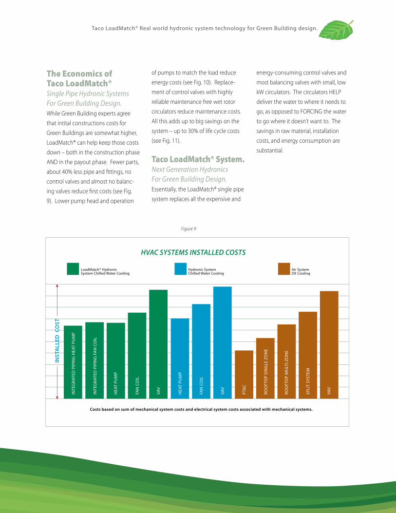
The Economics of Taco LoadMatch® Single Pipe Hydronic Systems For Green Building Design.While Green Building experts agree
that intital constructions costs for
Green Buildings are somewhat higher,
LoadMatch® can help keep those costs
down – both in the construction phase
AND in the payout phase. Fewer parts,
about 40% less pipe and fittings, no
control valves and almost no balanc-
ing valves reduce first costs (see Fig.
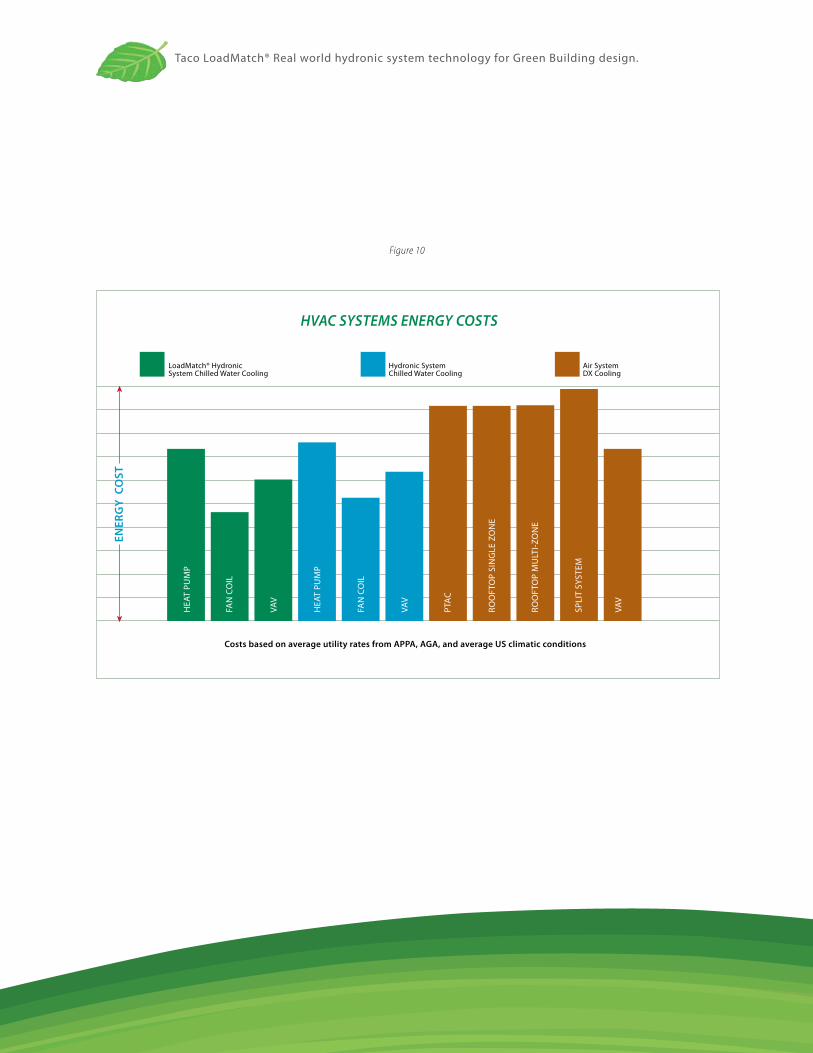
9). Lower pump head and operation
of pumps to match the load reduce
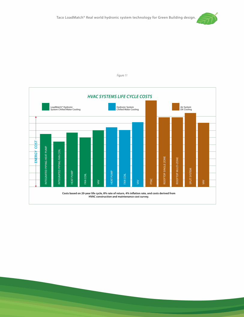
energy costs (see Fig. 10). Replace-
ment of control valves with highly
reliable maintenance free wet rotor
circulators reduce maintenance costs.
All this adds up to big savings on the
system – up to 30% of life cycle costs
(see Fig. 11).
Taco LoadMatch® System. Next Generation Hydronics For Green Building Design.Essentially, the LoadMatch® single pipe
system replaces all the expensive and
energy-consuming control valves and
most balancing valves with small, low
kW circulators. The circulators HELP
deliver the water to where it needs to
go, as opposed to FORCING the water
to go where it doesn’t want to. The
savings in raw material, installation
costs, and energy consumption are
substantial.
Figure 9
Taco LoadMatch® Real world hydronic system technology for Green Building design.
Figure 10
Taco LoadMatch® Real world hydronic system technology for Green Building design.
Figure 11
You’ll be more comfortable.LoadMatch® provides better comfort than all air-systems, as well as conventional hydronic systems. LoadMatch® is a self balancing system and assures the required flow to all heating and cooling units at all times. Your heating and air conditioning system will deliver BTU’s where they’re needed, and when they’re needed.
You’ll save energy. With less pipe and the elimination of control valves and most balancing valves, lower pump head and less power is required to move the water.
You’ll save money.Fewer parts, about 40% less pipe and fittings, no control valves and almost no balancing valves reduce first costs. Lower pump head and operation of pumps to match the load reduce operating and maintenance costs. All this adds up to big savings on the system, typically up to 30% of life cycle costs.
Contact UsTaco engineers are at the forefront of Green Building hydronics, designing components and systems to help you meet the challenges of environmentally sensitive – and budget conscious – design and build. Visit our web site at taco-hvac.com or e-mail greenteam@taco-hvac for more information or to talk to a Taco Green Building professional.
Taco, Inc., 1160 Cranston Street, Cranston, RI 02920 (401) 942-8000 / Fax (401) 942-2360 Taco (Canada) Ltd. 6180 Ordan Drive, Mississauga, Ontario L5T 2B3 (905) 564-9422 / Fax (905) 564-9436
©Taco Catalog #100-13 Effective Date: 07/25/08Supersedes: 06/01/05 Printed in USA
www.taco-hvac.com
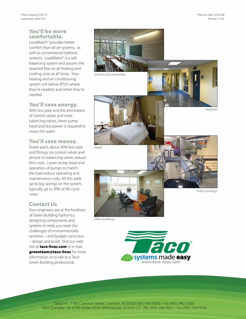
Schools and Universities
Hospitals
Hotels
Public buildings
Office buildings