greenwich academic literature archive (gala) academic literature archive (gala) – the university...
TRANSCRIPT

Greenwich Academic Literature Archive (GALA)– the University of Greenwich open access repository
http://gala.gre.ac.uk
__________________________________________________________________________________________
Citation:
Mason, David John (1991) A study of the modes of gas-solids flow in pipelines. PhD thesis, Thames Polytechnic.
__________________________________________________________________________________________
Please note that the full text version provided on GALA is the final published version awarded
by the university. “I certify that this work has not been accepted in substance for any degree,
and is not concurrently being submitted for any degree other than that of (name of research
degree) being studied at the University of Greenwich. I also declare that this work is the result
of my own investigations except where otherwise identified by references and that I have not
plagiarised the work of others”.
Mason, David John (1991) A study of the modes of gas-solids flow in pipelines . ##thesis _type## ,
##institution##
Available at: http://gala.gre.ac.uk/8686/
__________________________________________________________________________________________
Contact: [email protected]

1502335A THESIS
entitled
A STUDY OF THE MODES OF GAS-SOLIDS FLOW IN
PIPELINES
Submitted in partial fulfilment of the requirements for the award of the
;:y
DEGREE OF DOCTOR OF PHILOSOPHY ^
of the
COUNCIL FOR NATIONAL ACADEMIC AWARDS
by
DAVID JOHN MASON, BSc (Eng),
Centre For Numerical Modelling And Process AnalysisSchool Of Mathematics, Statistics And Computing
And School Of EngineeringFaculty Of Technology
Thames PolytechnicLONDON
November 1991

So what you think? I ast.
I think us here to wonder, myself. To wonder. To ast. And that in wondering bout the big things and asting bout the big things, you learn about the little ones, almost by accident.
From The Color Purple by Alice Walker.

ABSTRACT
A variety of gas-solids flows can be observed in the pipeline of a pneumatic conveying system. These flows may be classified as one of three modes:
i. suspension flow;ii. non-suspension moving-bed type flow;iii. non-suspension plug type flow.
The modes of flow that a bulk material can achieve are dependent upon its particle and bulk properties as well as the pipeline conditions. This work describes the development of mathematical models for these modes of flow as well as experimental investigations to determine the validity of the models proposed.
The modelling technique was based upon the solution of the conservation equations for inter-dispersed continua. Mathematical models for phenomena, such as the aerodynamic drag force between the conveying gas and particles, were added to the general mathematical model so that the flow of the gas-solids mixture could be simulated. This resulted in successful development of models for the prediction of suspension flow and non-suspension moving-bed type flow.
In addition to providing data for validation of the mathematical models, the experimental programme produced a number of other observations. For example, it was found that the solids velocity in non-suspension moving-bed type flow could be determined non-intrusively by pressure measurements due to the variation in height of the moving-bed with time at a fixed location. More importantly, observation of plug type flow has led to the proposal of a mechanism to describe the development of the flow along a pipeline.
11

AUTHOR'S NOTE
All the work in this thesis is the sole and original work of the author, except where stated otherwise by acknowledgement or reference.
in
ACKNOWLEDGEMENTS
Numerous people have provided me with invaluable support throughout this work. Firstly, I would like to thank all those involved in the supervision of this project at various stages: Professor M Cross, Professor AR Reed, Professor NC Markatos and Dr MK Patel. I would also like to thank all my fellow reseach students in both the School of Mathematics and School of Engineering, especially Nicole and Cos whose managed to survive three years in the same office.
This work would not have been possible without the support of the staff of Computer Centre, and the technicians at the Laboratory. In particular I would like to acknowledge the support of Robert Painter and Andrew Mason.
Finally I would thank my Mum and Dad for their constant support during the production of this thesis.
This work was funded from the Science and Engineering Research Council's Specially Promoted Programme in Particulate Technology.
IV

CONTENTS
NOMENCLATURE ................................. x
1 INTRODUCTIONpage
1.1 PNEUMATIC CONVEYING ...................... 2
1.2 CURRENT SYSTEM DESIGN PRACTICE ............. 4
1.3 OBJECTIVES OF THIS STUDY .................... 6
1.4 STRUCTURE AND SCOPE OF THE THESIS ........... 7
2 REVIEWpage
2.1 INTRODUCTION ............................. 9
2.2 MODES OF GAS SOLIDS FLOW IN PIPELINES ........ 9
2.3 CLASSIFICATION OF BULK MATERIALS ACCORDINGTO MODES OF FLOW ......................... 16
2.4 MATHEMATICAL MODELS ..................... 232.4.1 INTRODUCTION ......................... 232.4.2 EXPERIMENTAL INVESTIGATIONS ........... 232.4.3 MATHEMATICAL MODELS FOR MULTI-PHASE
GAS-SOLIDS FLOW ...................... 272.4.3.1 INTRODUCTION ................. 272.4.3.2 CRITERIA FOR ANALYSING GAS-SOLIDS
FLOW MODELS ................. 282.4.3.3 LOW SOLIDS CONCENTRATION
FLOWS ....................... 292.4.3.4 HIGH SOLIDS CONCENTRATION
FLOWS ....................... 35
2.5 SUMMARY ................................ 37
v

3 THE MATHEMATICAL MODELpage
3.1 INTRODUCTION ............................ 39
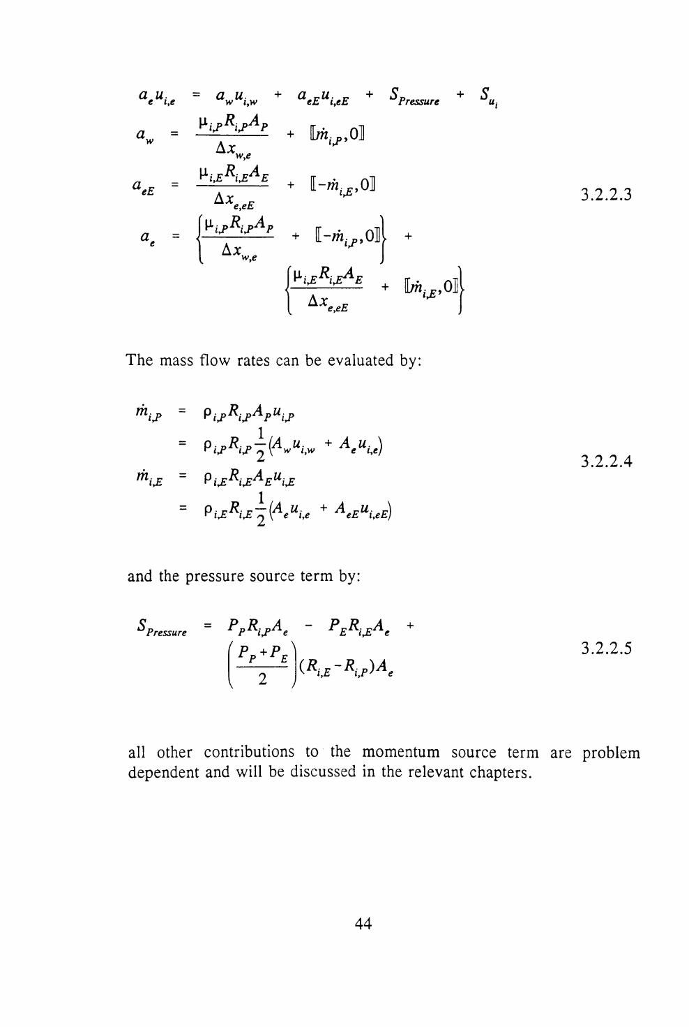
3.2 THE CONSERVATION EQUATIONS ............... 393.2.1 THE CONSERVATION OF MASS .............. 403.2.2 THE CONSERVATION OF MOMENTUM ........ 433.2.3 THE GENERAL CONSERVATION EQUATION .... 453.2.4 PROBLEM SPECIFIC RELATIONSHIPS ......... 46
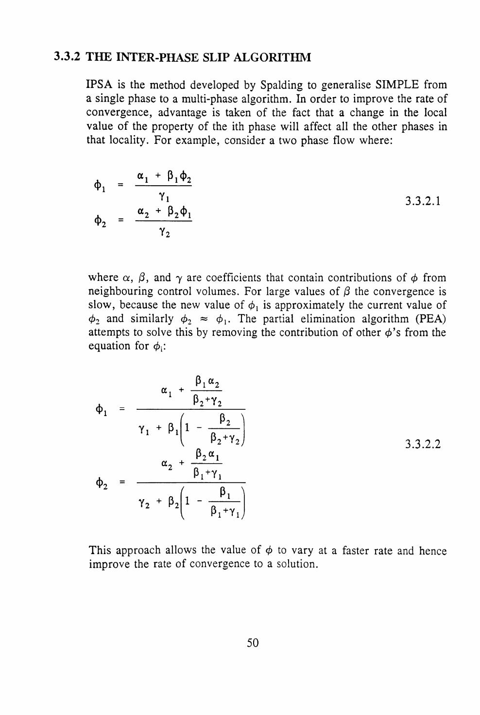
3.3 THE SOLUTION PROCEDURE ................... 483.3.1 SOLVING THE CONSERVATION EQUATIONS .... 483.3.2 THE INTER-PHASE SLIP ALGORITHM ......... 50
3.4 SUMMARY ................................ 52
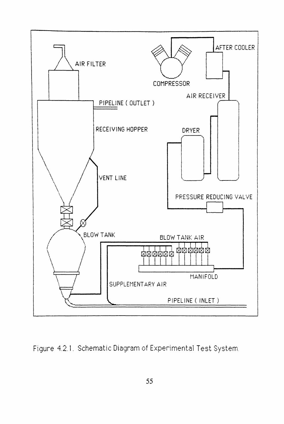
4 EXPERIMENTAL EQUIPMENTpage
4.1 INTRODUCTION ............................ 54
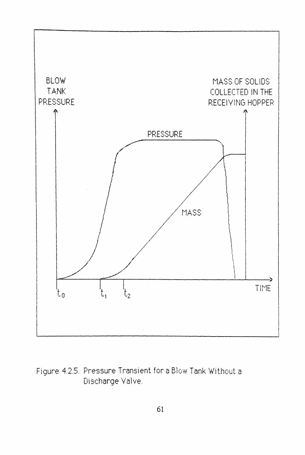
4.2 SYSTEM OVERVIEW ......................... 544.2.1 THE SUPPLY OF COMPRESSED GAS .......... 564.2.2 THE SOLIDS FEED DEVICE ................. 564.2.3 THE PIPELINE .......................... 604.2.4 THE RECEIVING HOPPER .................. 63
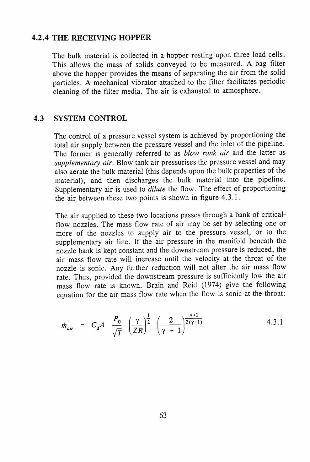
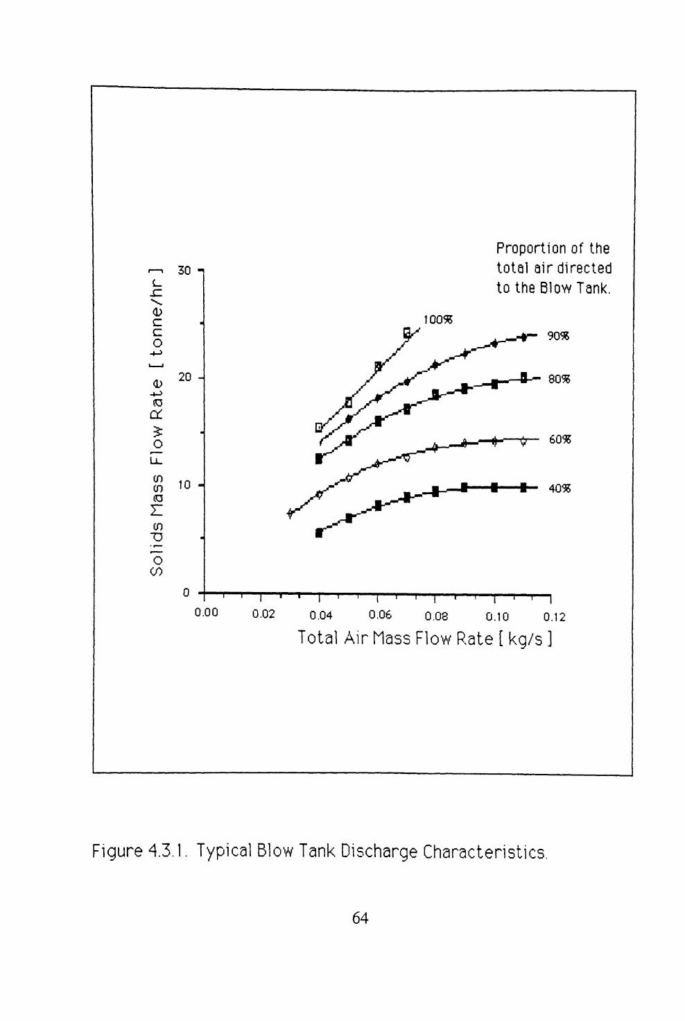
4.3 SYSTEM CONTROL .......................... 63
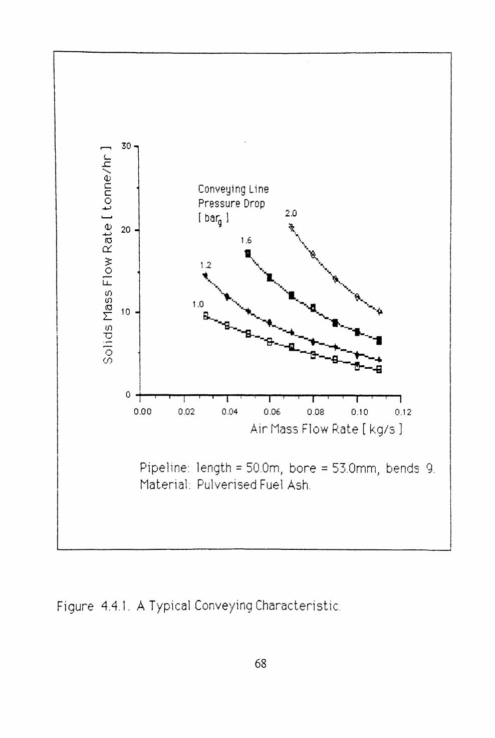
4.4 DATA MEASUREMENT AND COLLECTION .......... 67
4.5 SUMMARY ................................ 72
VI

5 MODELLING OF SUSPENSION FLOWpage
5.1 INTRODUCTION ............................ 74
5.2 RELATIONSHIP BETWEEN FLOW CONDITIONS ANDSLIP VELOCITY ............................ 75
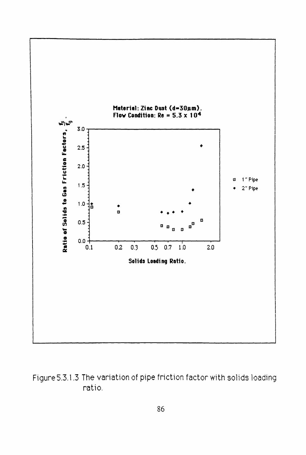
5.3 GAS SOLIDS INTERACTIONS ................... 795.3.1 HEAT AND MASS TRANSFER ............... 795.3.2 MOMENTUM TRANSFER ................... 83
5.4 OTHER RELATIONSHIPS ...................... 875.4.1 WALL EFFECTS ......................... 875.4.2 DESCRIPTION OF THE PHASES .............. 87
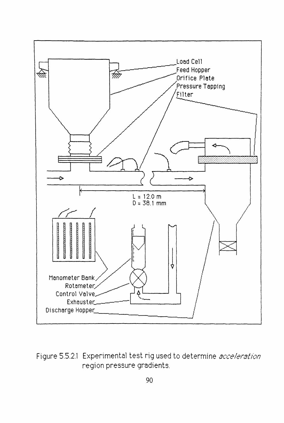
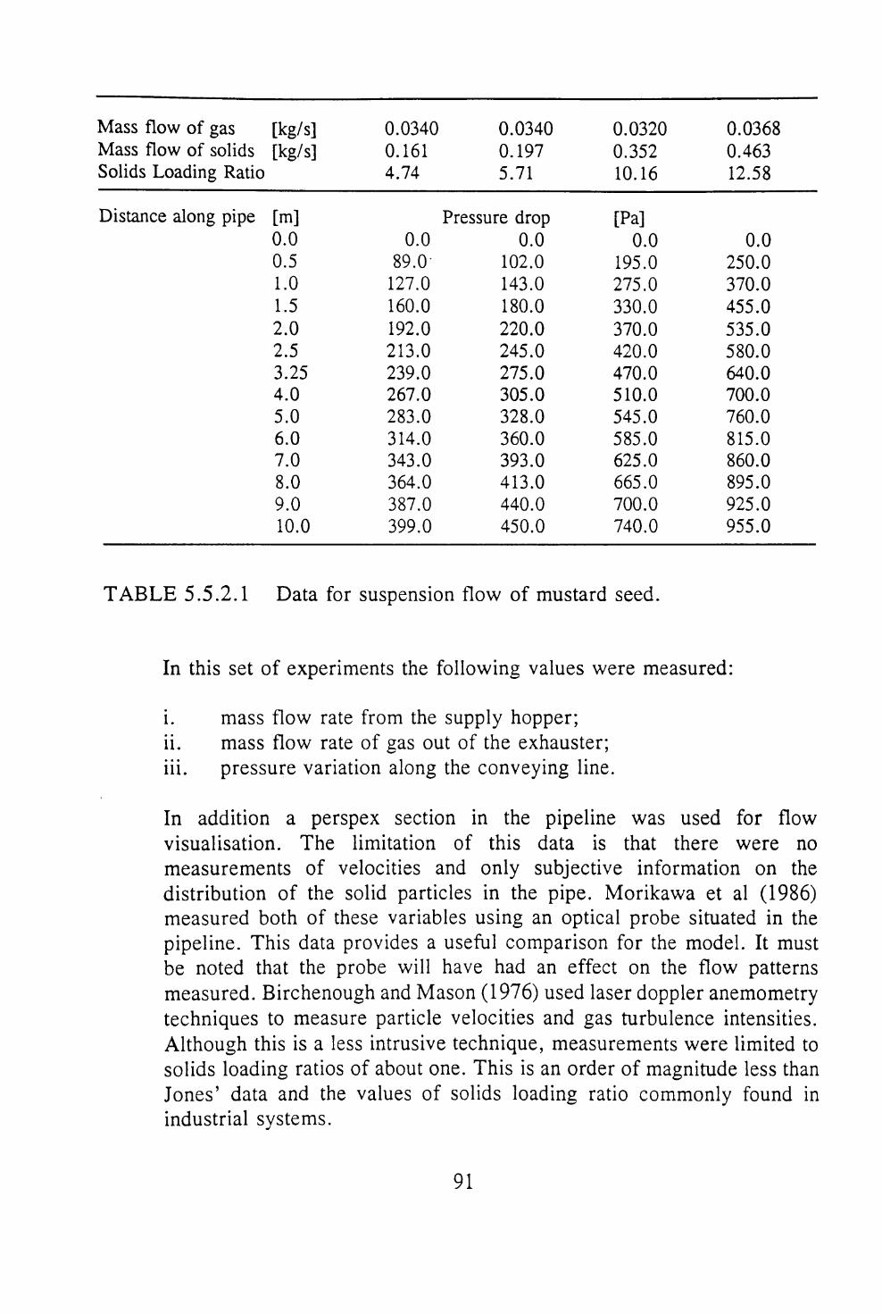
5.5 COMPARISON WITH EXPERIMENTAL DATA ........5.5.1 INTRODUCTION .........................5.5.2 EXPERIMENTAL DATA .................... 895.5.3 DISCRETISATION OF THE FLOW DOMAIN, AND
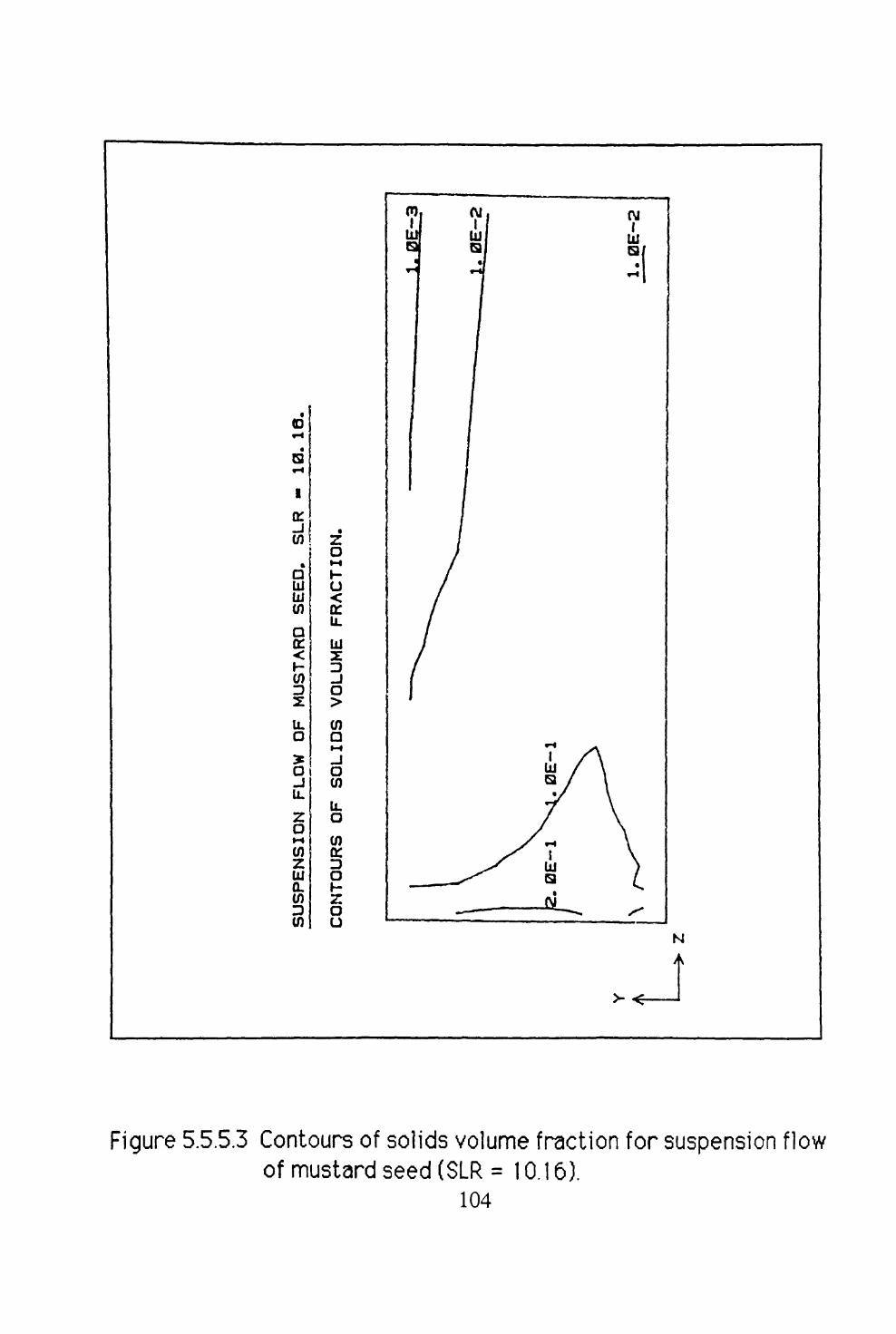
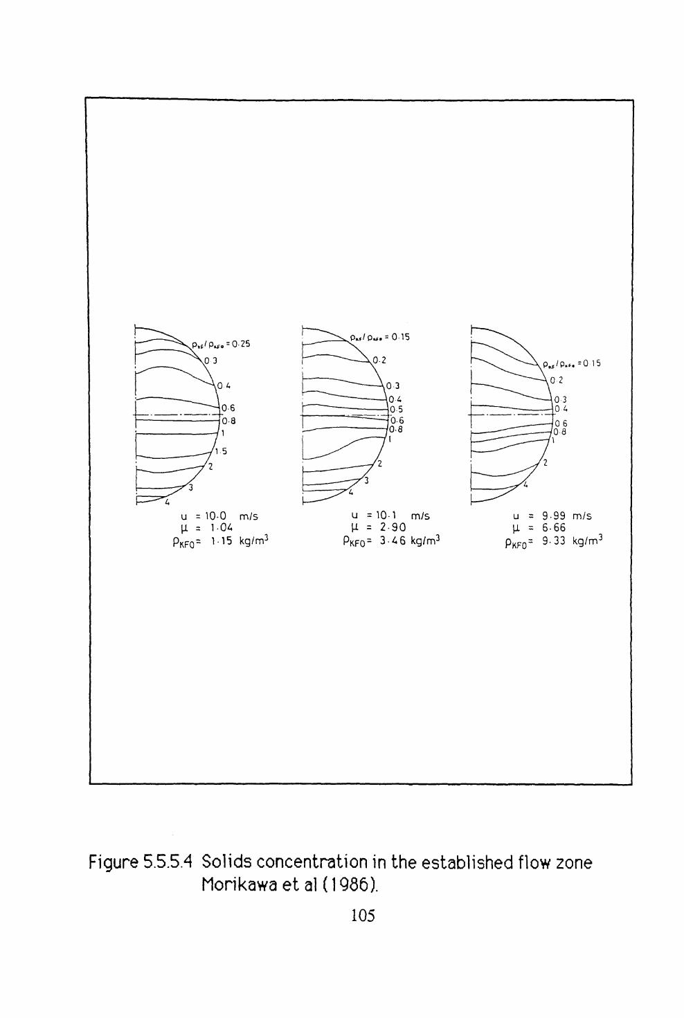
CALCULATION PROCEDURE ................ 935.5.4 PREDICTION OF THE PRESSURE DROP ........ 955.5.5 THE PREDICTION OF SOLIDS CONCENTRATIONS 100
5.6 SUMMARY OF MODEL PERFORMANCE ............ 109
6 NON-SUSPENSION MOVING-BED FLOWpage
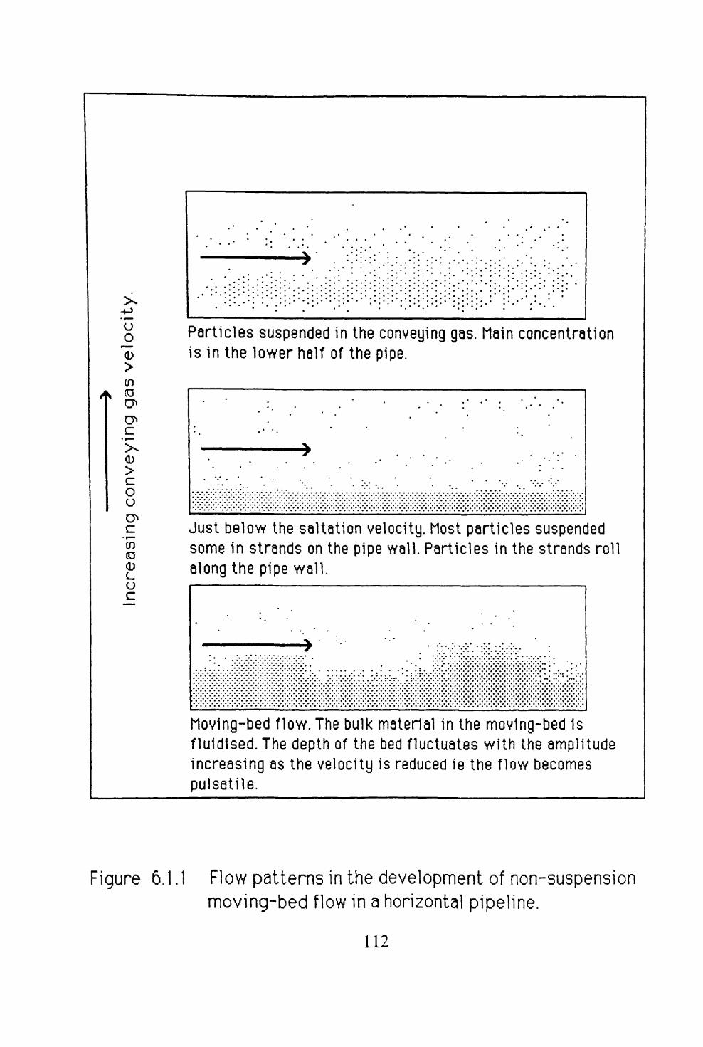
6.1 INTRODUCTION ............................ Ill
6.2 DEVELOPMENT OF THE MATHEMATICAL MODEL ... 1146.2.1 DEFICIENCIES OF THE SUSPENSION FLOW
MODEL ............................... 1146.2.2 PARTICLE-PARTICLE EFFECTS .............. 1156.2.3 PARTICLE-WALL EFFECTS ................. 1166.2.4 PARTICLE PACKING ..................... 1206.2.5 DIFFUSION OF THE GAS OUT OF THE BULK
MATERIAL ............................ 1206.2.6 PARTICLE PRESSURE ..................... 122
vn

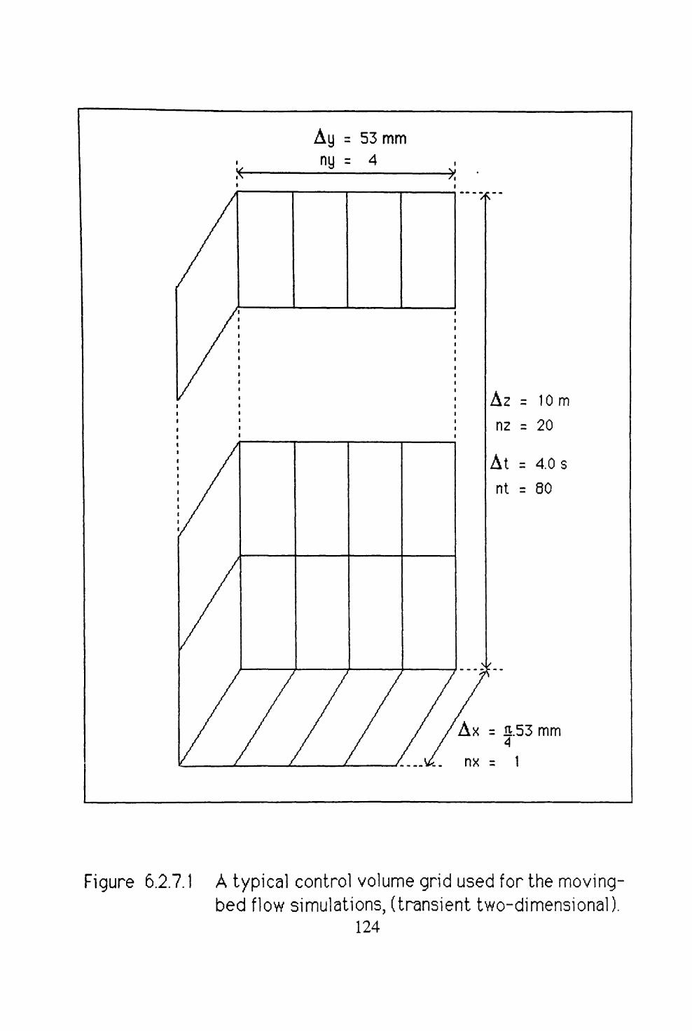
6.2.7 DISCRETISATION OF THE FLOW DOMAIN ...... 123
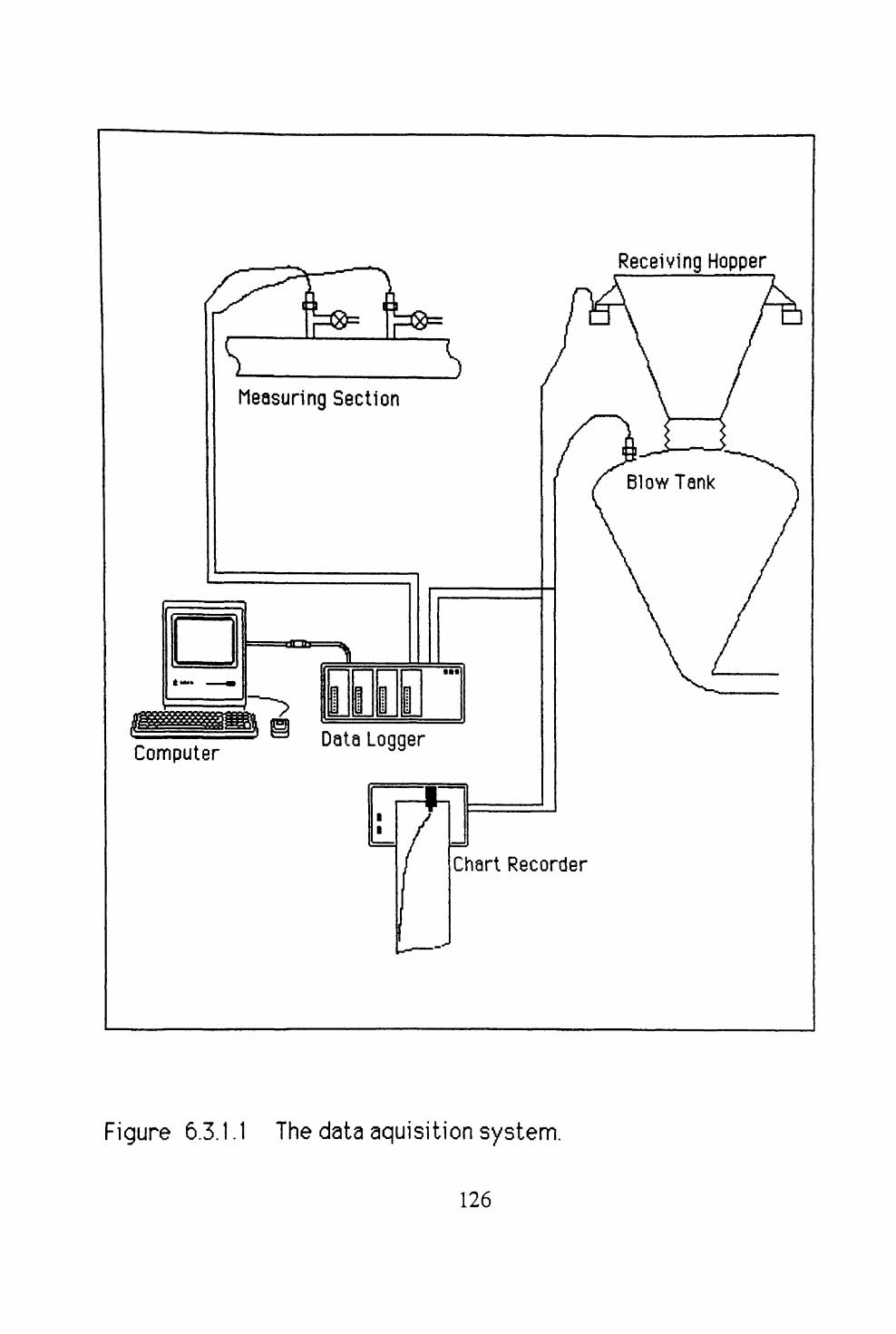
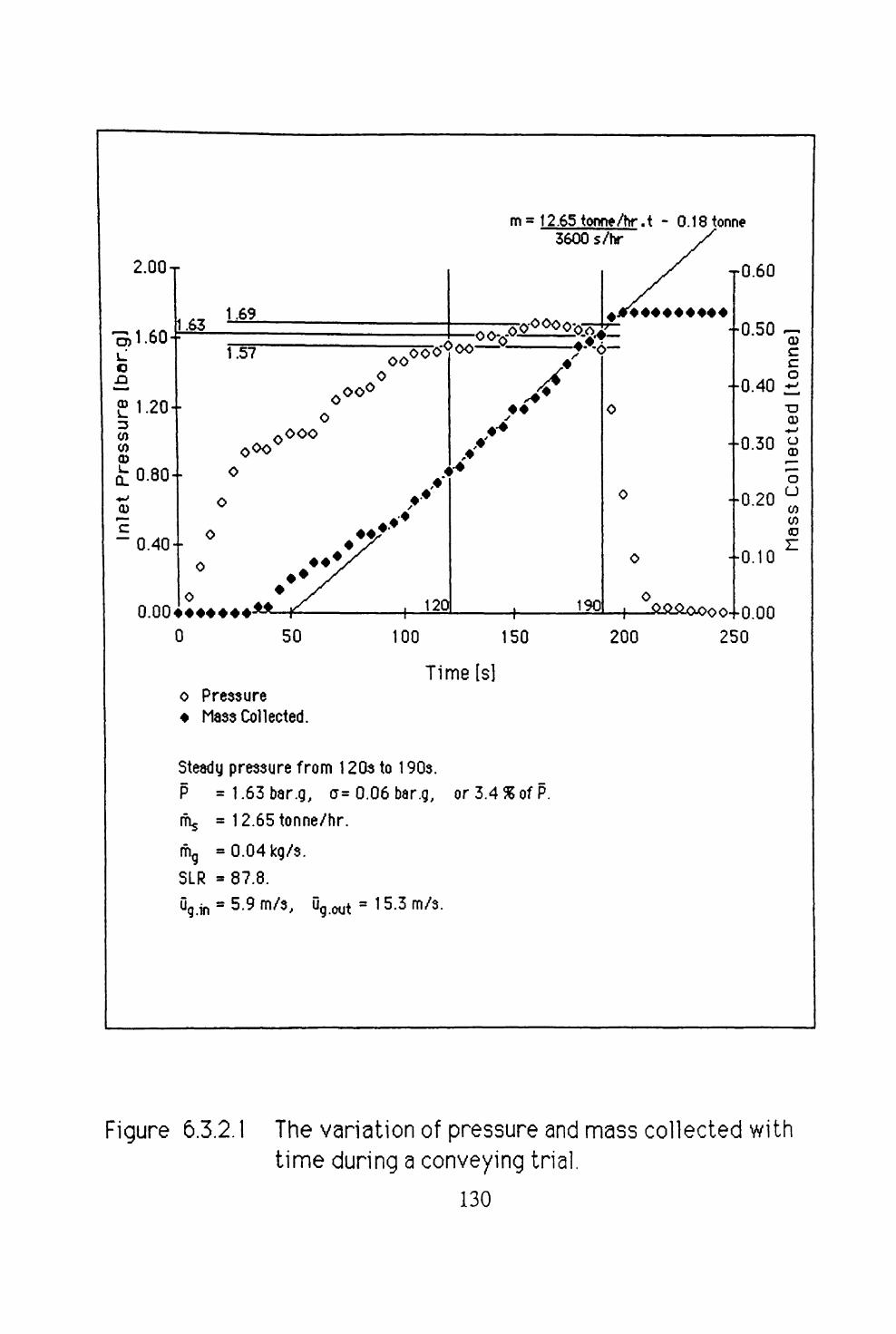
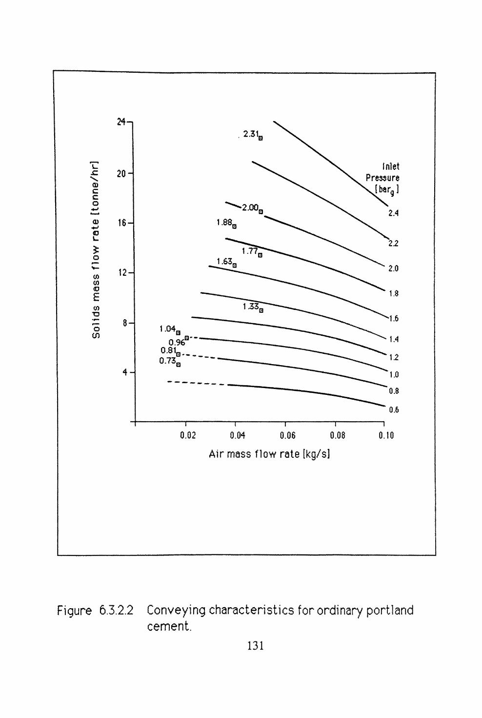
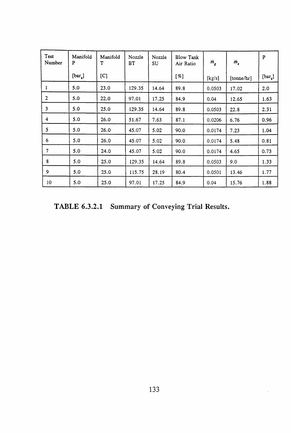
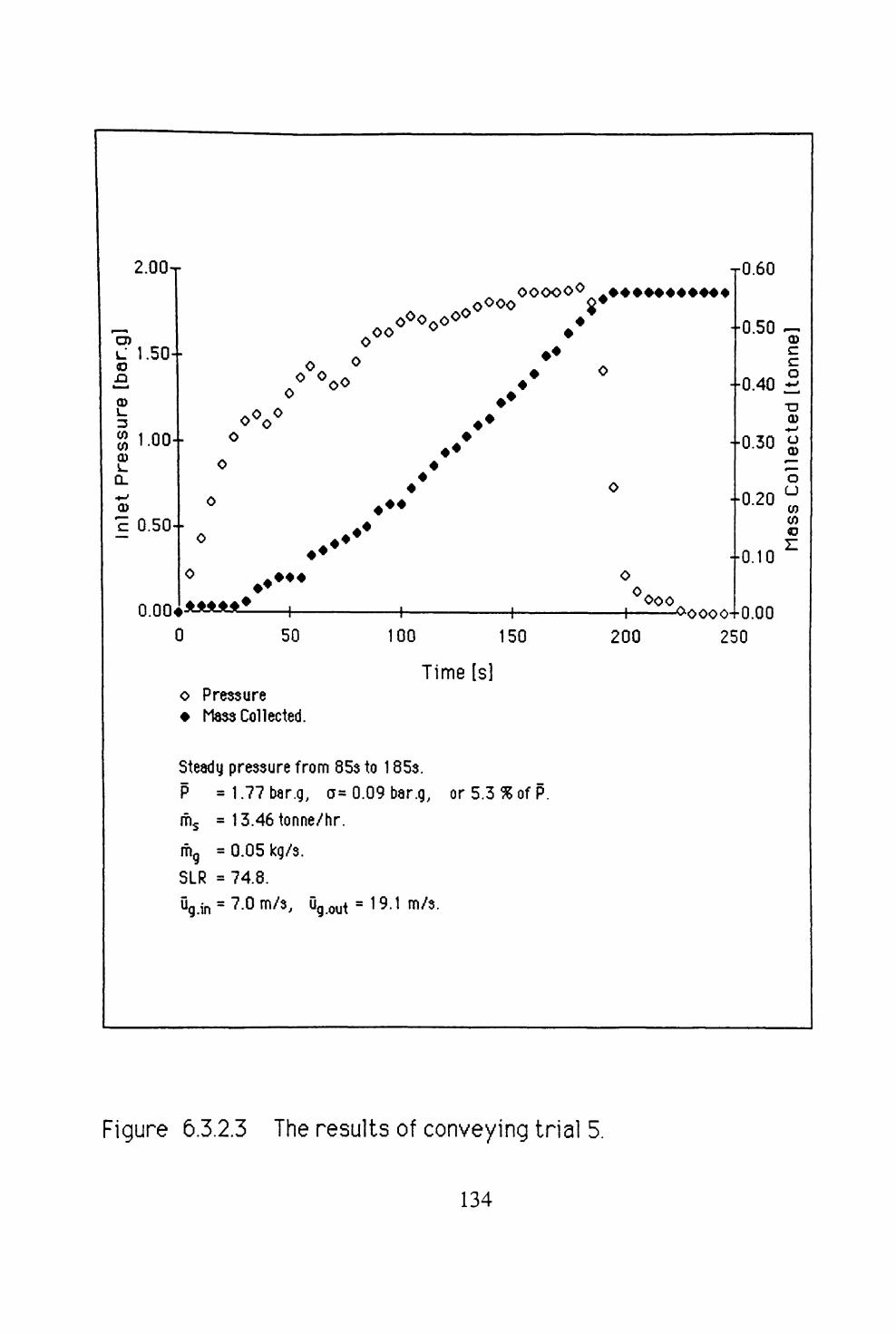
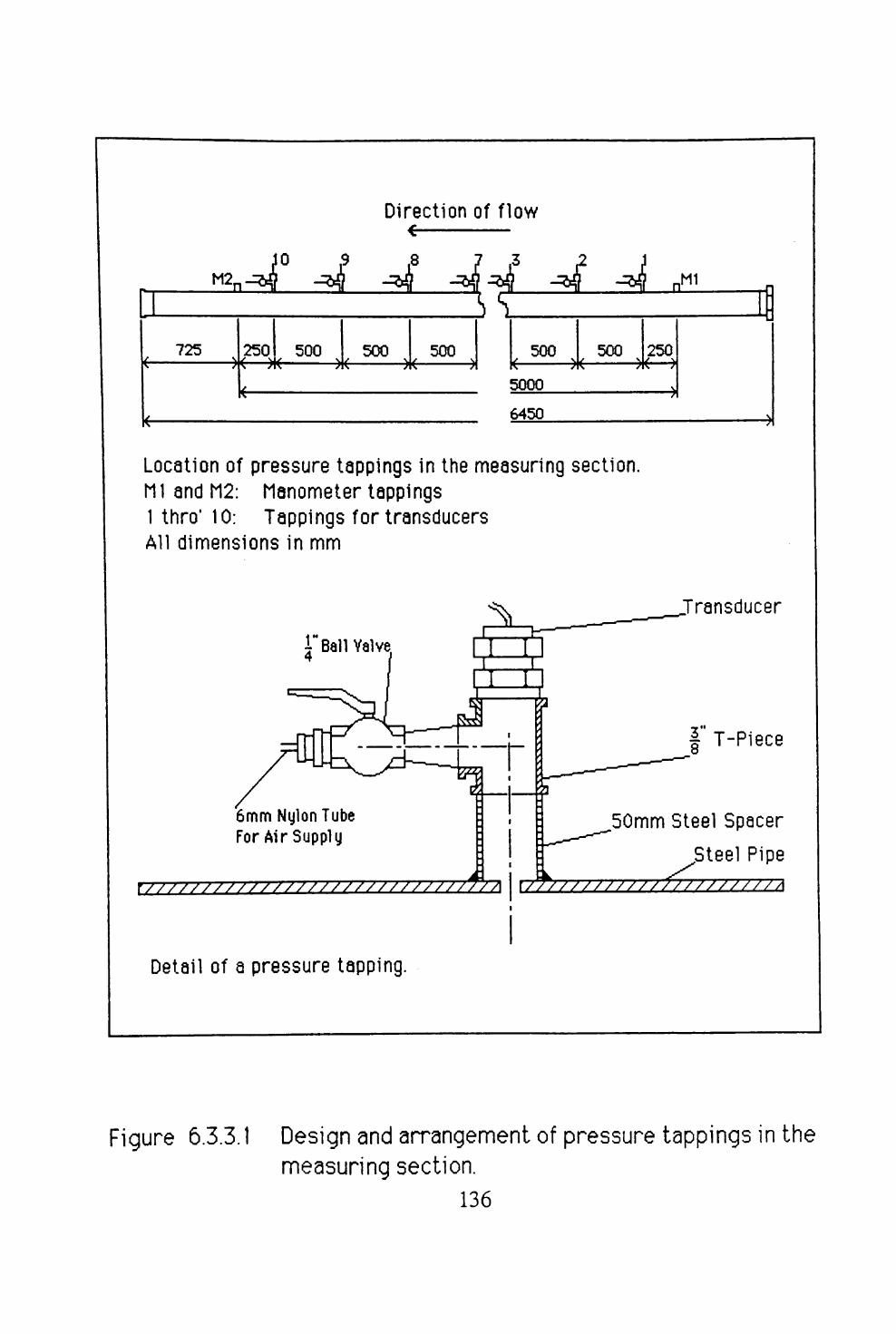
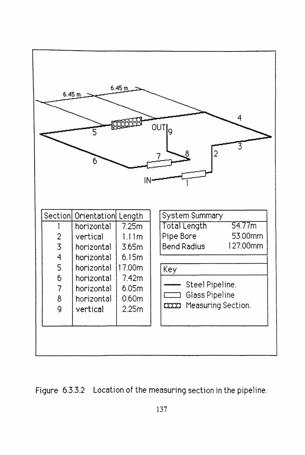
6.3 EXPERIMENTAL INVESTIGATION ................ 1256.3.1 INTRODUCTION ......................... 1256.3.2 GLOBAL DATA ......................... 1256.3.3 LOCAL DATA .......................... 1356.3.4 INTERPRETATION OF DATA FROM A FAST SCAN
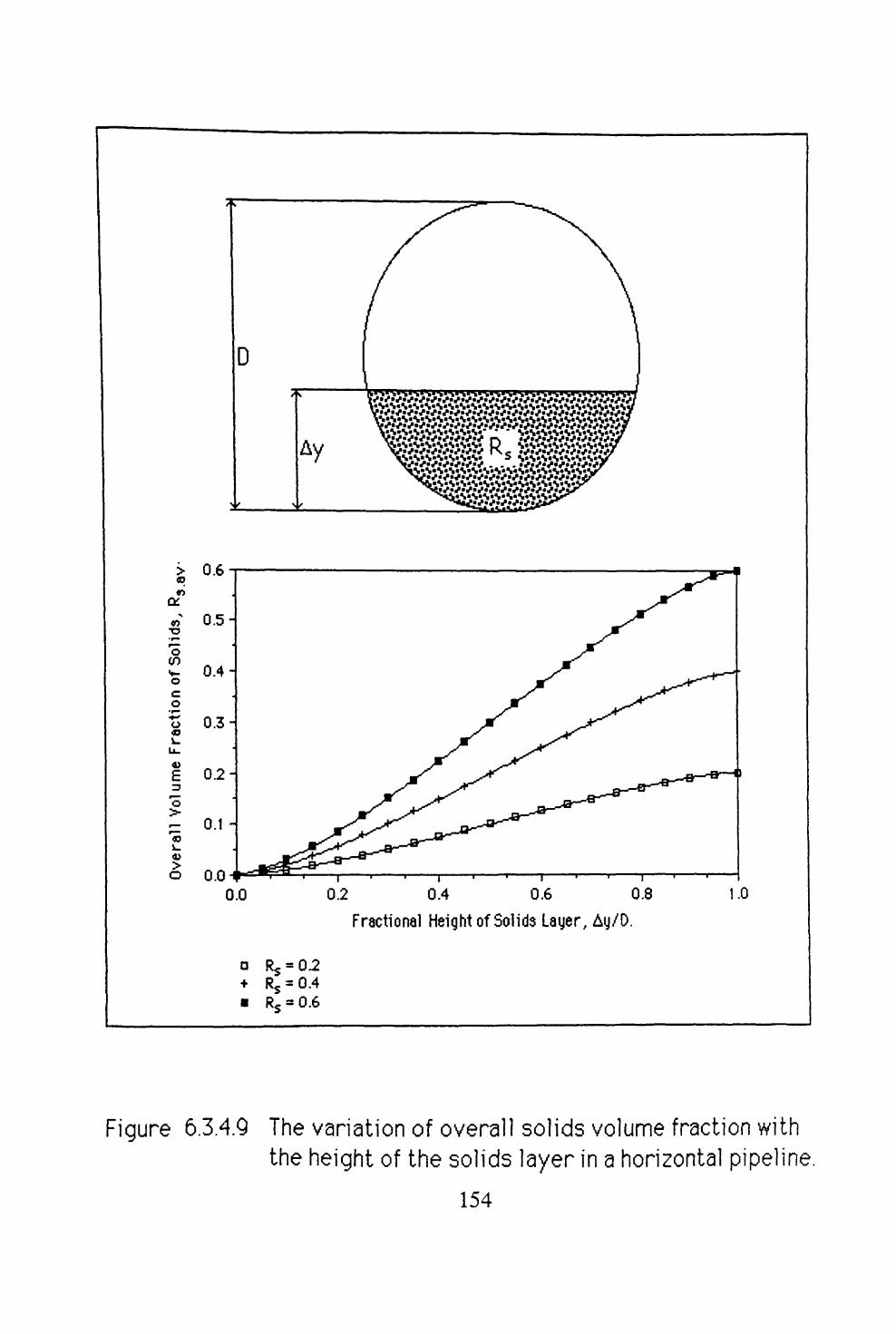
TEST ................................. 1406.3.5 SUMMARY OF TEST RESULTS .............. 153
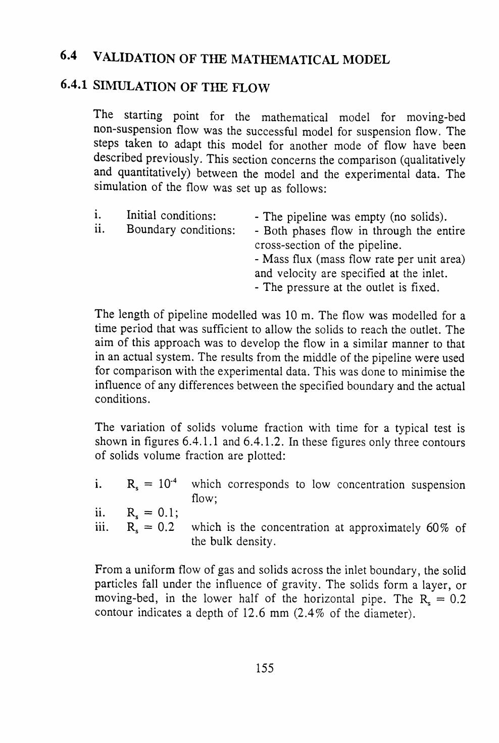
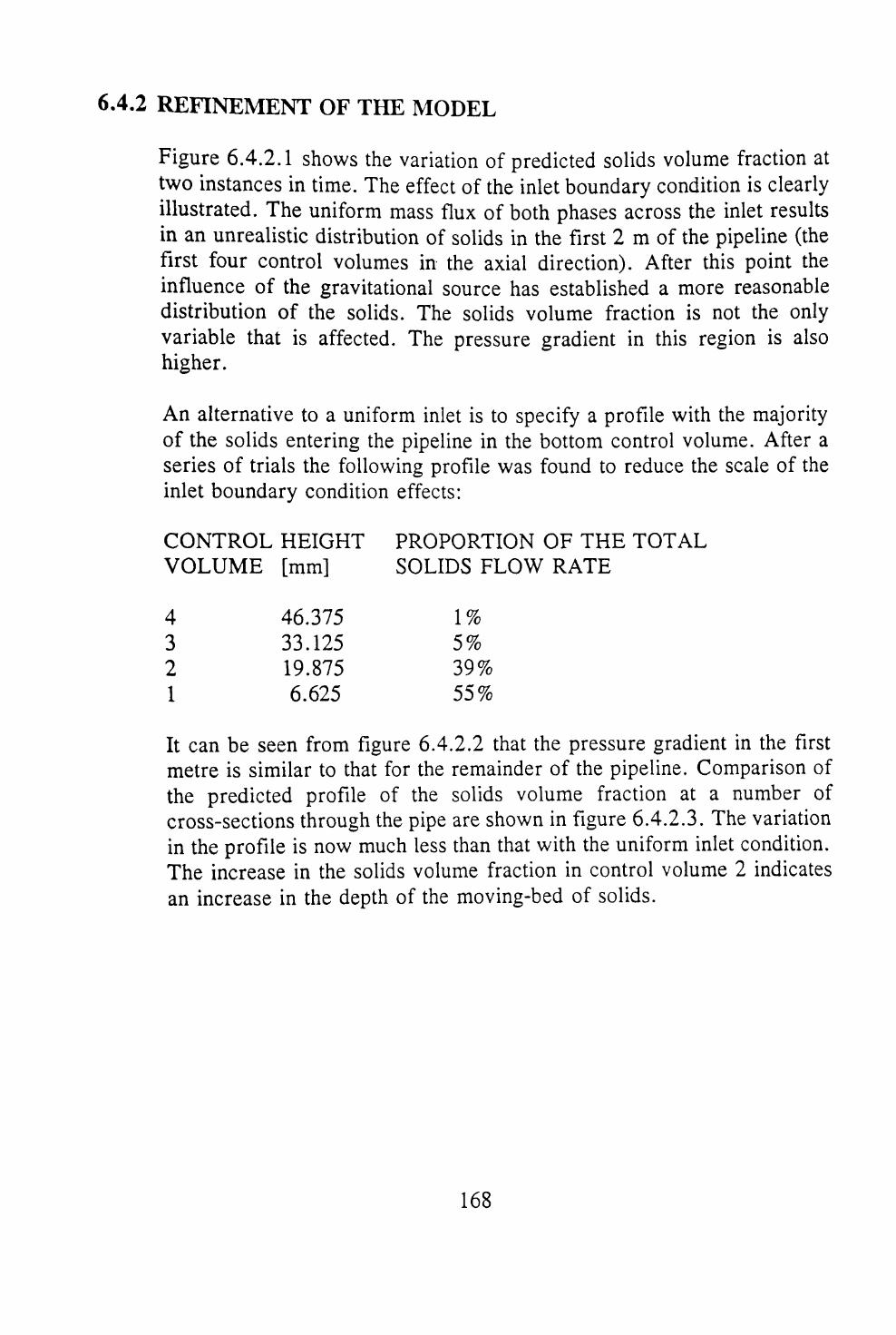
6.4 VALIDATION OF THE MATHEMATICAL MODEL ..... 1556.4.1 SIMULATION OF THE FLOW ................ 1556.4.2 REFINEMENT OF THE MODEL .............. 168
6.5 SUMMARY ................................ 179
7. NON-SUSPENSION PLUG TYPE FLOWpage
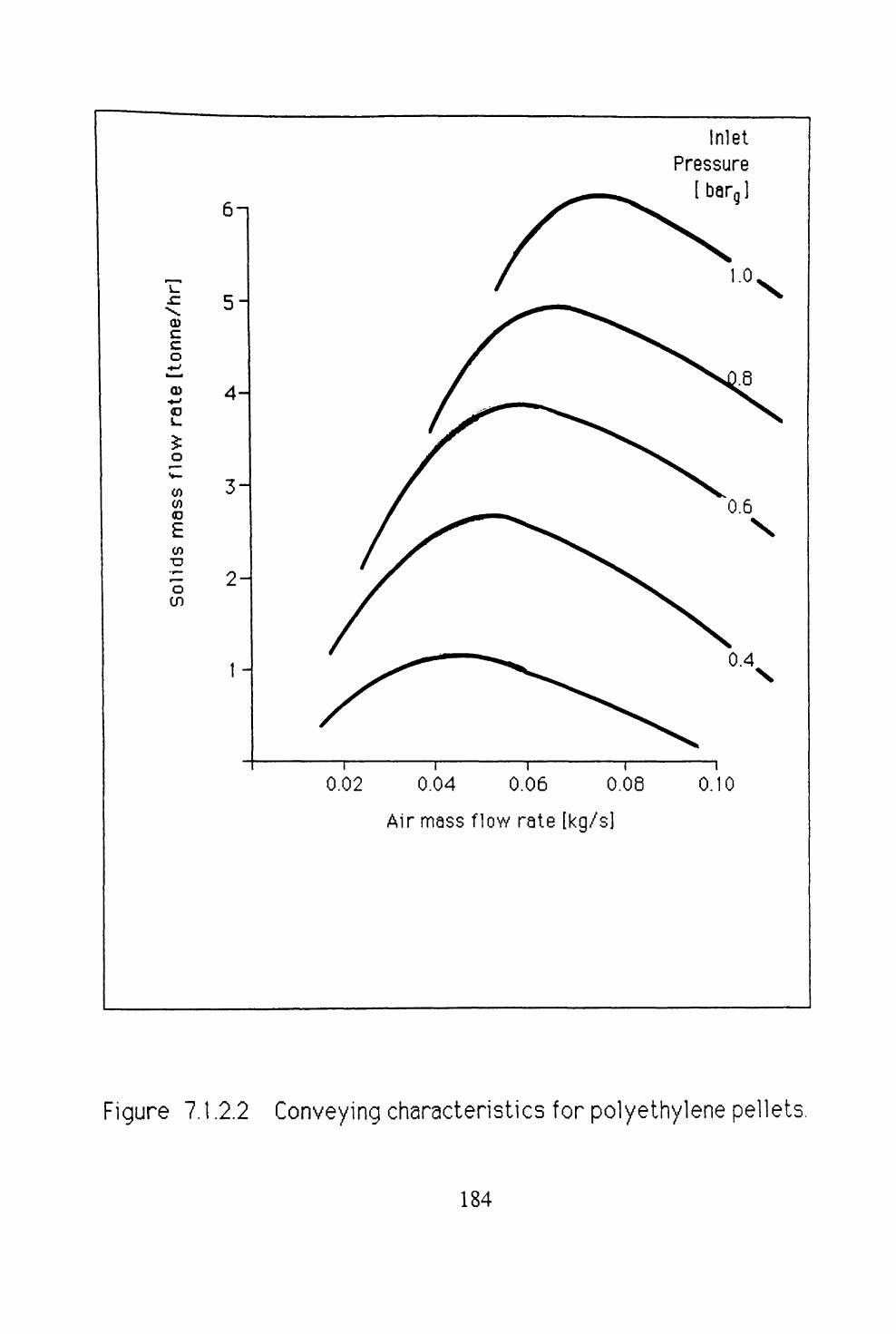
7.1 INTRODUCTION ............................ 1817.1.1 PLUG FLOW MATERIALS .................. 1817.1.2 A DEFINITION OF PLUG FLOW .............. 181
7.2 MODELS FOR PLUG FLOW ..................... 1857.2.1 ANALYSIS OF A SINGLE PLUG .............. 1857.2.2 ANALYSIS OF SHEARING TYPE FLOW ......... 1887.2.3 DISCRETE VERSUS CONTINUUM MODELS ...... 190
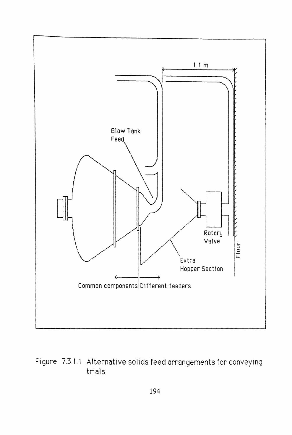
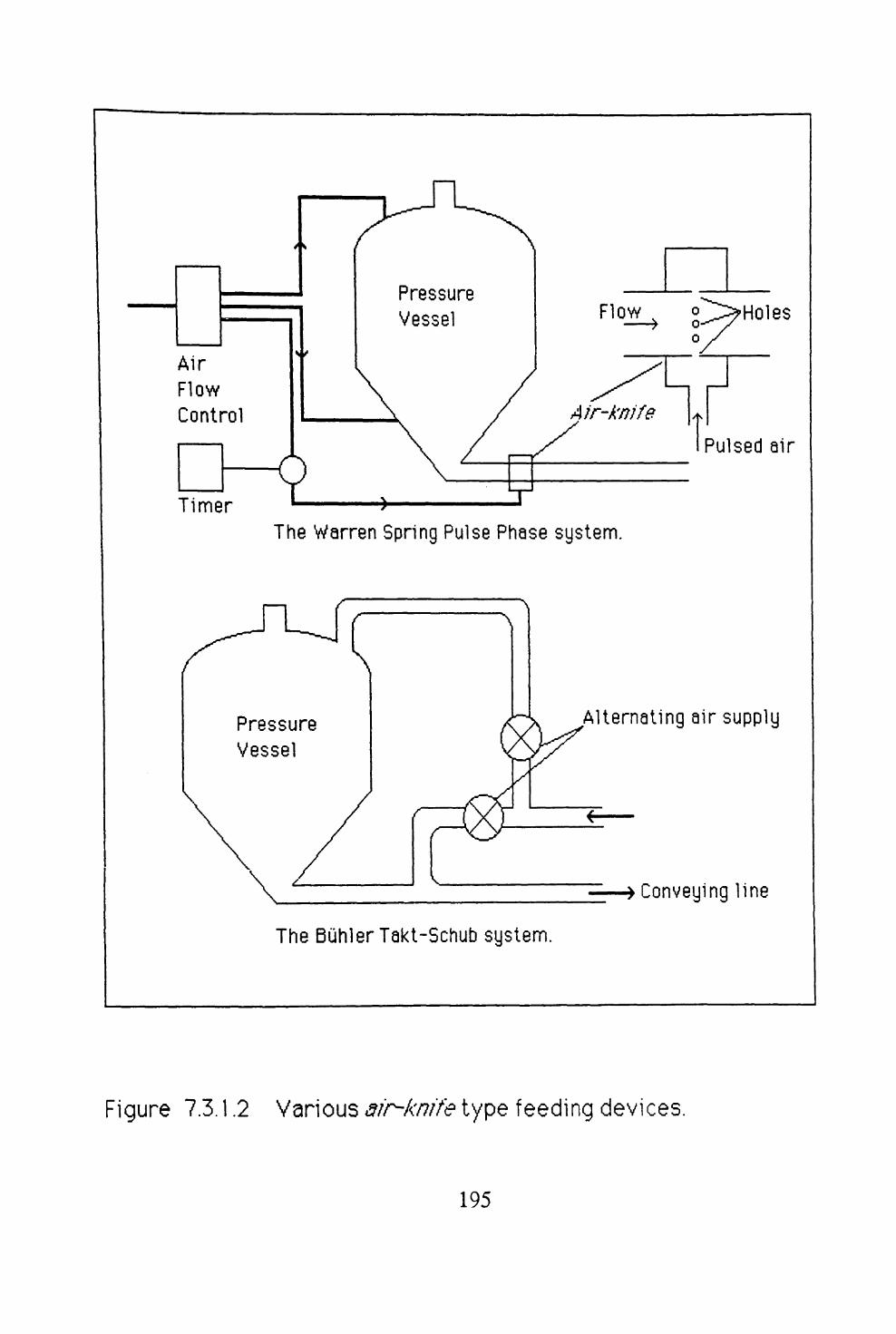
7.3 EXPERIMENTAL OBSERVATIONS ................ 1937.3.1 FLOW VISUALISATION AND TRIALS WITH
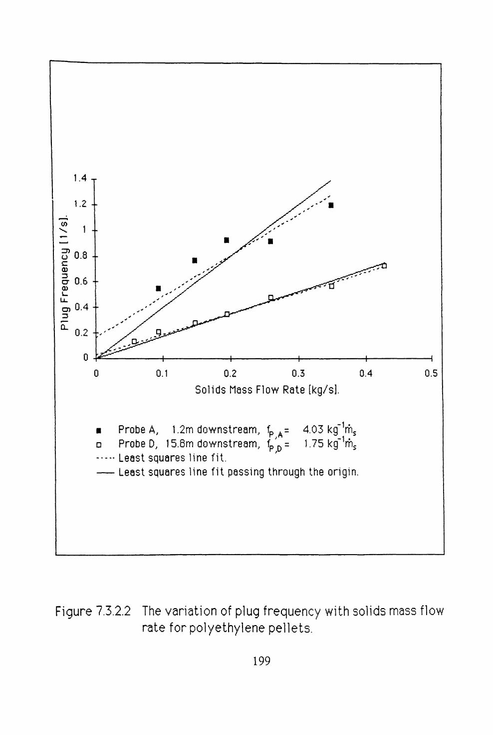
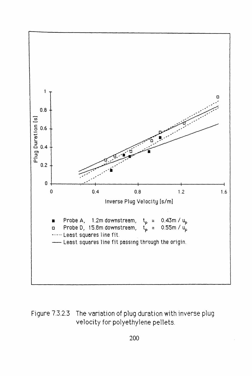
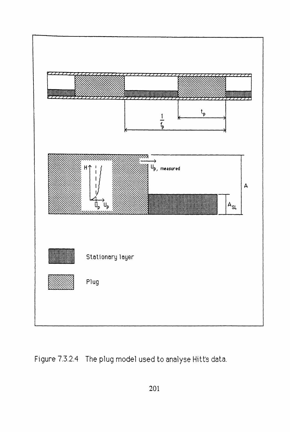
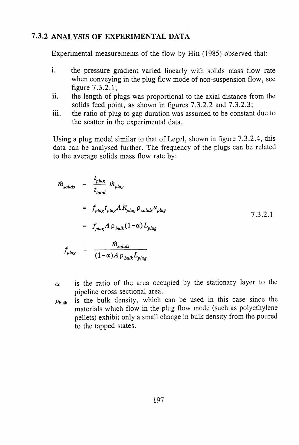
DIFFERENT FEEDERS ..................... 1937.3.2 ANALYSIS OF EXPERIMENTAL DATA ......... 197
7.4 SUMMARY ................................ 203
Vlll
8 CONCLUSIONpage
8.1 SUMMARY OF ACHIEVEMENTS ................. 2058.1.1 GENERAL SUMMARY ..................... 2058.1.2 SUSPENSION FLOW ...................... 2058.1.3 NON-SUSPENSION MOVING-BED FLOW ........ 2058.1.4 NON-SUSPENSION PLUG FLOW .............. 206
8.2 AREAS FOR FURTHER INVESTIGATION ........... 207
REFERENCES .................................. 209
IX

NOMENCLATURE
A Flow area normal to the direction of flow. A Pr0j Projected area of an object used in the calculation of
aerodynamic drag (equation 5.3.2.1), defined in equation
a Coefficient in conservation equation.b Coefficient in conservation equation.CD Coefficient of drag for an object.Cd Coefficient of dischage from an orifice.CP Specific heat at constant pressure.C^ Coefficient used in the linearisation of a source term, defined
in equation 3.2.4.2.G! Variable defined by equation 2.4.3.3.2.c2 Variable defined by equation 2.4.3.3.3.D Pipe diameter.ds Particle diameter.FD Drag force on an object.Fi Shear force due to the viscosity of the ith phase.Fr Froude number, defined by equation 2.4.3.3.3.fe Gas pipe friction factor.fs Solids pipe friction factor.G Multiplier used in the linearisation of a source term, defined
in equation 3.2.4.2.g Acceleration due to gravity. k Turbulent kinetic energy. rhe Gas mass flow rate.rhi Mass flow rate of the ith phase.rhm Mass flow rate of gas-solids mixture, defined in equation
5.3.1.1.ms Solids mass flow rate.P Pressure.R Gas constant from the ideal gas equation (equation 3.2.4.1).Rg Volume fraction of gas.Rj Volume fraction of ith phase, defined by equation 3.2.1.Rs Volume fraction of solids.Re Reynolds number.ReD Pipe Reynolds number, defined in equation 5.4.1.2.Res Particle Reynolds number, defined in equation 5.3.2.3.SRi Source term for the conservation of mass equation for the ith
phase.

Sp Term used in the linearisation of a source term (equation3.2.4.2), defined in equation 3.2.4.3.
SPressure Pressure source term in the conservation of momentumequation.
Sui Source term for the conservation of momentum equation forthe ith phase.
S0 Source term in the general conservation equation. SLR Solids loading ratio, defined by equation 2.2.1. Tg Temperature of gas. Tm Temperature of gas-solids mixture, defined in equation
^J ^J
Ts Temperature of solids.Ug Superficial gas velocity, Ug = Rgug.ug Velocity of gas.Uj Velocity of the ith phase.us Velocity of solid particles.Usiip Slip velocity, uslip = ug - us.ust Terminal velocity of a single particle.V cv Volume of a control volume.Vj Volume occupied the ith phase in a control volume.V^ Value used in the linearisation of a source term, defined in
equation 3.2.4.2.Z Compressibility factor (Z = l for an ideal gas).a. Solids pressure drop function, defined by equation 2.4.2.1./3 Variable defined by equation 2.4.2.4b.T^ Diffusion coefficient.7 Ratio of specific heats, 7 = CP/CV .AP Pressure drop.APg Pressure drop due to gas only.APS Pressure drop due to solids only.Ax Distance between two points in x direction,e Turbulence dissipation rate.X s Solids friction factor, defined by 2.4.3.3.2.
Dynamic viscosity of fluid.Effective dynamic viscosity used in turbulence models.
PL Kinematic viscosity of fluid. £ Variable defined by equation 2.4.2.4c. pbulk Density of bulk material, pbulk = R,ps . pe Density of gas.
o
p- Density of the ith phase.pmixture Density of gas-solids mixture, defined by equation 2.4.3.3.1.
XI

ps Density of solid particle.rs Intergranular shear stress.<j> Conserved variable in the general conservation equation.
xn

1 INTRODUCTION

1.1 PNEUMATIC CONVEYING
Pneumatic conveying is the transportation of solid particles by a gas (generally air) through a pipeline. The origins of pneumatic conveying can be traced to the latter end of the nineteenth century. One of the earliest successful applications being the Duckham pneumatic grain elevator for ship unloading Anon.O (1887). Pneumatic conveying systems are highly flexible, yet simple systems that may be used to transport a wide range of powdered and granular materials. A pneumatic conveying system may be considered as comprising of four elements, as illustrated in figure 1.1.1:
i. a source of compressed gas;ii. a device to feed solid particles into the pipeline;iii. the conveying pipeline;iv. a device to separate the solids from the gas.
A multiplicity of industries employ pneumatic conveying. The following list indicates a small sample of these and some bulk particulate materials that are transported:
i. food industry floor, sugar, tea, fish;ii. agriculture grain, rice, animal feed pellets;iii. oil industry barytes, cement, bentonite;iv. power generation pulverised coal, ash;v. chemical industry polyethylene pellets, PVC powder.
The first trials to determine relationships between the properties of the gas and solid particles, and those of the flowing suspension were reported in the early nineteen-twenties, for example, the work of Cramp and Priestly (1925). These early systems transported solid particles in suspension, in the gas stream. By the late forties workers such as Albright et al (1949) had started to investigate alternative conveying systems employing modes of flow in which the solid particles were not suspended in the gas stream. Resistance to the adoption of these new systems was due to the frequency with which pipelines became blocked. This was especially true with poorly designed systems.


Some advantages of systems characterised by non-suspension modes of flow are:
i. lower energy consumption;ii. reduced particle degradation;Hi. less pipeline erosion.
The second two effects result primarily from the lower velocities encountered in such systems. The first effect is dependent largely upon the type of bulk particulate material conveyed and the actual mode of flow achieved. The drawback to such systems is the increased complexity of the design procedure.
1.2 CURRENT SYSTEM DESIGN PRACTICE
When considering the design of a pneumatic conveying system, the designer starts with the following information:
i. the type of bulk particulate material to be conveyed;ii. the required delivery rate for the bulk particulate material;iii. the distance the bulk particulate material is to be transported.
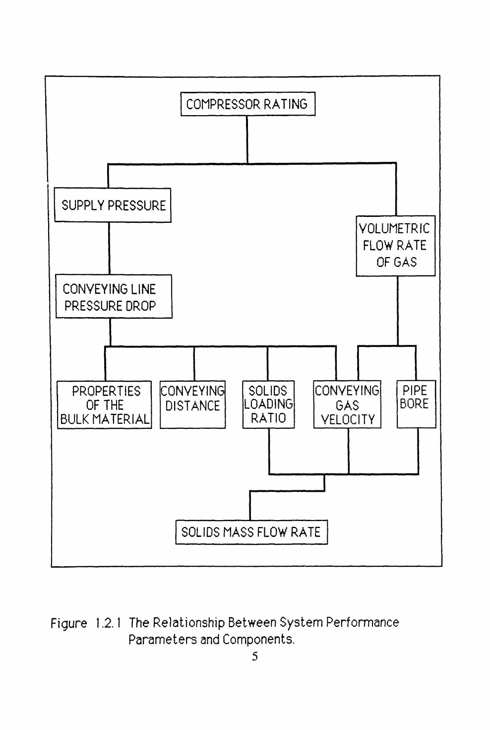
Figure 1.2.1 shows the interdependence of the various parameters of the conveying system upon each other. This illustrates the importance of determining the pressure drop necessary to convey the bulk particulate material for a given set of operational parameters. From a knowledge of the gas requirements of the system the four system elements (illustrated in figure 1.1.1) may be selected. Current design practice employs one of the following methods to obtain this information:
i. the application of an empirical correlation, for example Rose andBarnacle (1957);
ii. the use of data acquired from similar existing systems; iii. the use of data from tests on pilot size plant, for example Mills
(1979).

The difficulty with all these methods, to varying degrees, is the need to scale the data in order for it to be applicable to the actual system. The parameters involved in such a scaling process are:
i. the pipe diameter;ii. the length and orientation of the pipeline;iii. the number of bends in the pipeline.
From the results of this scaling procedure a suitable set of operating conditions may be used to define a system which can successfully transport the bulk material as specified.
1.3 OBJECTIVES OF THIS STUDY
While the procedure outlined in the previous section has proved reliable, considerable care is required when the actual system differs significantly from the pilot plant. The current demand for:
i. longer pipelines;ii. higher throughputs;iii. lower energy costs;iv. better product quality (ie less particle degradation);
has exacerbated an already complex situation to a point which encourages the development of new design procedures. Consequently, those workers involved in the design of such systems have begun to explore alternative methods. The minimum requirement of any new design procedure is that it must provide a confidence check on the system parameters produced by a conventional design method. Therefore the aims of this research programme may be summarised as follows:
i. to analyse the physical phenomena that influence the flow of gas-solids mixtures in pipelines, with particular reference to situations in which the solid particles are not suspended in the gas;
ii. to develop mathematical models for these phenomena, and to use the models to predict the performance of a pneumatic conveying system;
iii. to acquire sufficient experimental data to validate these models.

1.4 STRUCTURE AND SCOPE OF THE THESIS
In accordance with the first objective of the research programme previously published work was reviewed to identify:
i. the possible modes of gas-solids flow in pipelines;ii. a means of characterising bulk particulate materials according to
their physical properties; iii. the methods employed to develop models of gas-solids flow in
pipelines.
A description of the general mathematical model employed in this programme is then given. An outline of the procedure used to solve the system of equations resulting from the general model is presented. Thus the tool for the computational simulations has been introduced. Subsequently the tool for the experimental element of the programme is described. Once the basic tools have been described, their application to the problem of gas-solids flow in pipelines is presented. Finally, comment is made on the success, or otherwise, of these experiments (computational and physical) and suggestions are made for further work.

2 REVIEW
2.1 INTRODUCTION
The starting point for the development of a mathematical model to describe a physical process is a conceptual view of the process. This conceptual view facilitates the identification of the important physical phenomena involved in the process. In the field of pneumatic conveying, this has led to numerous procedures for the classification of bulk particulate materials. These procedures use properties of both the bulk and the individual particles of the material to predict the potential modes of flow of the bulk material. This review assesses the various techniques, and demonstrates the reasoning behind the adoption of one of these methods.
The second part of this review considers the various methods available to analyse the process in light of the conceptual view of the process. The aim of this programme was to gain an insight into the mechanisms involved when a bulk material is transported through a pipeline by a gas. This insight also suggests certain types of mathematical approach for analysing the process.
2.2 MODES OF GAS SOLIDS FLOW IN PIPELINES
Pneumatic conveying systems have been classified traditionally according to the concentration of the bulk material in the pipeline. So-called dilute phase systems exhibit low solids concentrations, whilst dense phase systems have high solids concentrations. In general, dilute phase systems operate with gas velocities of sufficient magnitude to keep the majority of the bulk material suspended in the conveying gas. The dense phase description covers all other systems which operate generally at lower velocities. There is considerable ambiguity in the definition of dense phase according to the: classification method employed; the bulk material considered; and the type of system that is commercially marketed!
In order to avoid confusion by the use of the word phase to describe the components of the mixture flowing in the pipeline dilute phase systems will be referred to as suspension flow systems. This definition is different from that of Crowe (1982), who describes dilute gas-solids flow as a flow in which the particle motion is controlled by local aerodynamic forces and dense gas-solids flow as a flow in which particle motion is governed by particle-particle collisions. Both of these types of flow occur in suspension

flow systems, with the former characteristics dominating.
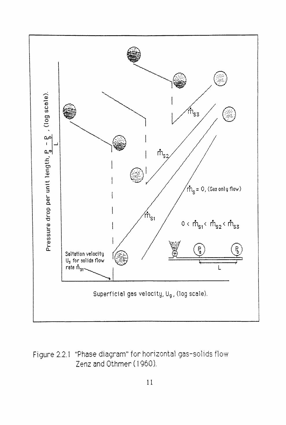
Zenz and Othmer (1960), show qualitative phase diagrams for the transport of bulk materials in both horizontal and vertical pipelines. These are reproduced in figures 2.2.1 and 2.2.2.
The saltation velocity, us, in the horizontal pipeline is the boundary between suspension and non-suspension flow. The choking velocity, uc , in the vertical pipeline is the boundary between flow and no-flow. For a vertical pipeline the boundary between suspension and non-suspension flow is the velocity at which counter-flow of solids begins.
All other flowing gas-solid systems will be referred to as non-suspension flow systems. These operate in the region below us in horizontal pipelines. It should be noted that since the mass flow rate of the conveying gas is constant and the gas density falls as the pipeline exit is approached, a system may exhibit first non-suspension flow and then suspension flow as the gas expands. Numerous workers have used the dimensionless quantity, phase density, also known as the solids loading ratio, to define the boundary between suspension and non-suspension flow.
Solids Loading Ratio, SLR = 2.2.1
The following illustrate the variations that have occurred by using this approach:
i. Ramachandran et al (1970), SLR > 25 to 100 for non-suspensionflow;
ii. Schuchart (1970), SLR > 100 for non-suspension flow; iii. Klinzing and Mathur (1981), SLR > 10 for non-suspension flow.
10
03
O CO
O)
Q.OI
I
O)
0)
CO CD
11

*CD
O
CLP I
QjJO
CD
CDCL
Q. O
0)
^^^^^s
12

The use of SLR is clearly limited since it takes no account of the volumetric concentration, or the properties of the bulk material. Dixon (1979) identified this fact by describing the maximum SLR as a function of:
i. bulk material properties;ii. pipeline geometry;iii. system operating condition.
Zenz and Rowe (1976) emphasized this point, stating that there is no simple numerical division between suspension and non-suspension modes of flow.
Most workers subsequently subdivide the non-suspension flow mode according to the flow regimes that may be observed within the pipeline. Wen and Simons (1959) identify three modes of non-suspension flow. These are described in order of decreasing conveying gas velocity:
i. segregation into a dense formation;ii. intermittent slugs of solids and gas;iii. a stationary layer with ripples travelling along its surface.
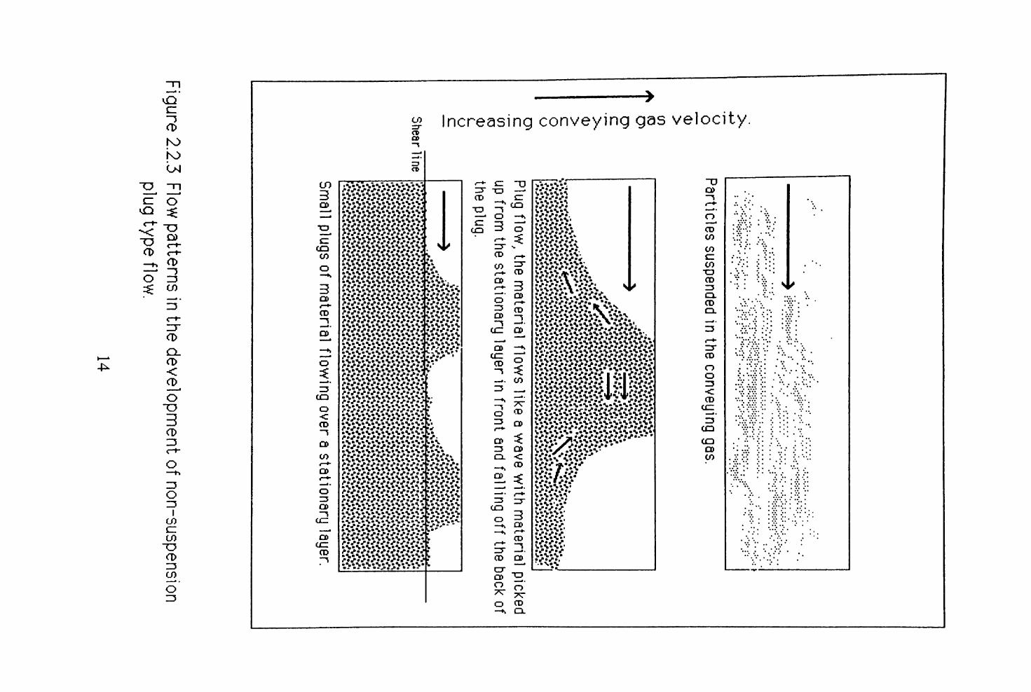
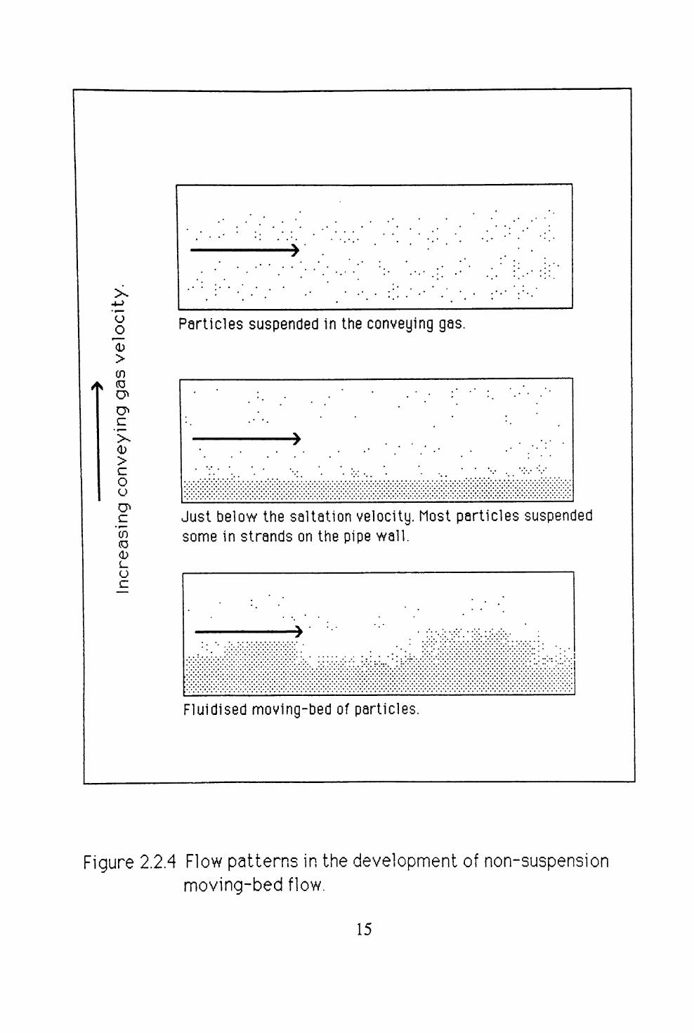
This type of classification is both material and pipeline dependent, and is subjective in nature. Furthermore, Wirth and Molerus (1982) reverses the order of modes (ii) and (iii), and further subdivide mode (i). The most common subdivision of non-suspension flow is into moving-bed type flow and plug-type flow. Konrad et al (1980), Hitt (1985), and Legel and Schwedes (1984) all describe plug-type flow. Figure 2.2.3 illustrates the main features of this mode of flow. Moving-bed type flow encompasses the Wen and Simons groups (i) to (iii), and is illustrated in figure 2.2.4. In summary, the following modes of flow have been identified:
i. Suspension flow;ii. Non-Suspension (moving-bed flow and plug flow).
13

H)
O)
0) O
<D
0>


/ / / 7 // ////////////////


4.4 DATA MEASUREMENT AND COLLECTION


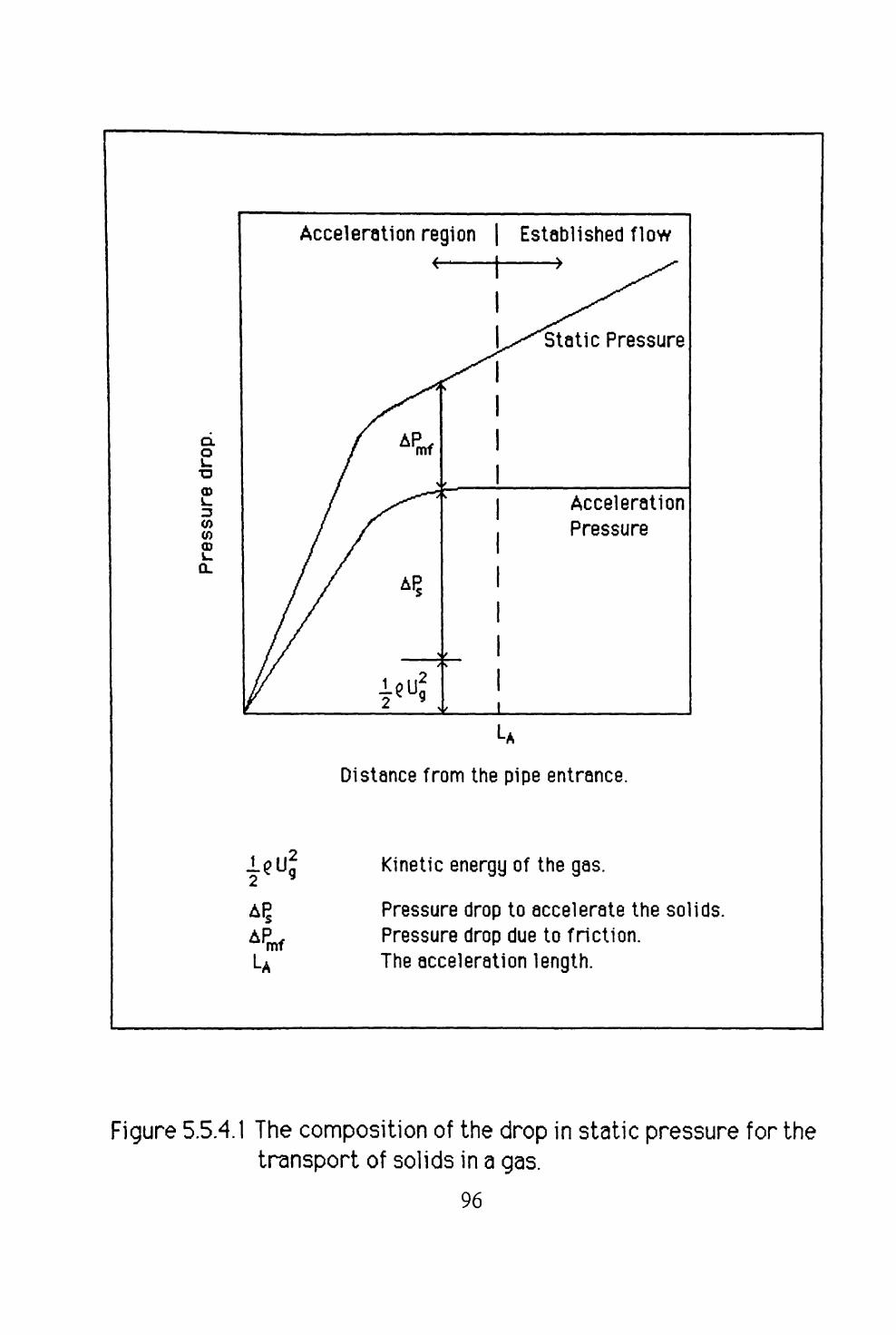
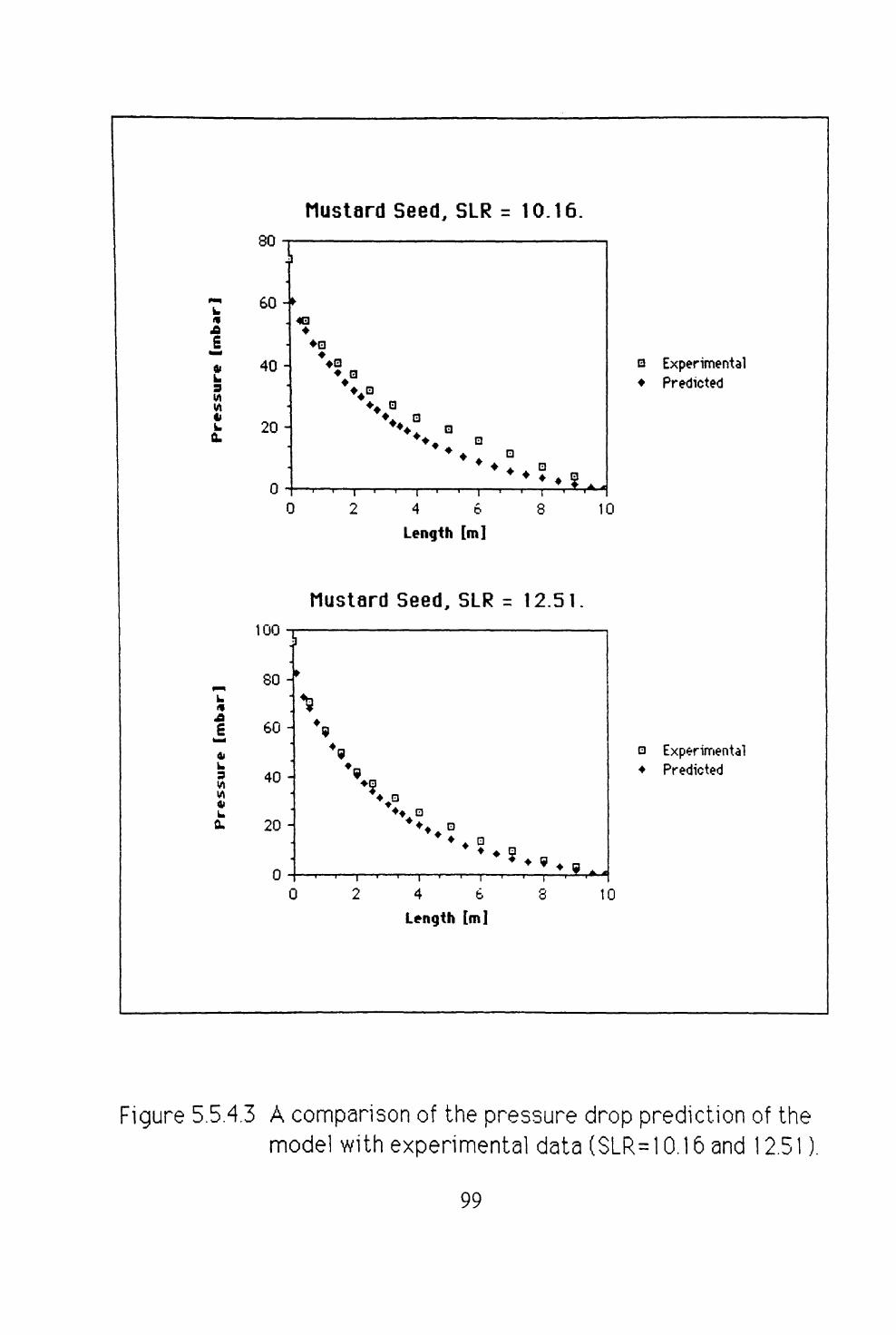
5.5.4 PREDICTION OF THE PRESSURE DROP


o <^+
CO
CO
1. 0E-1
1. 0E-2


CO
40


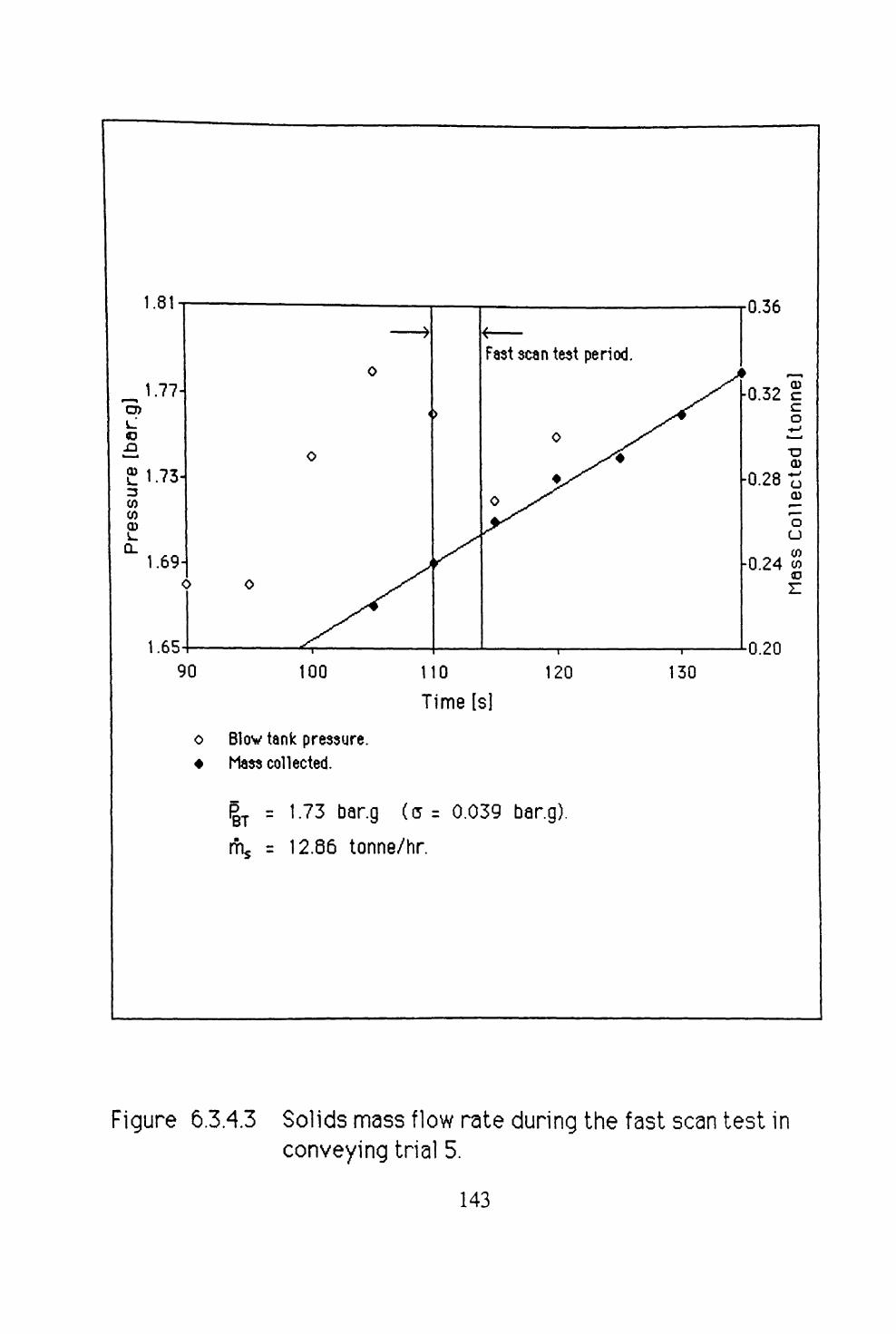
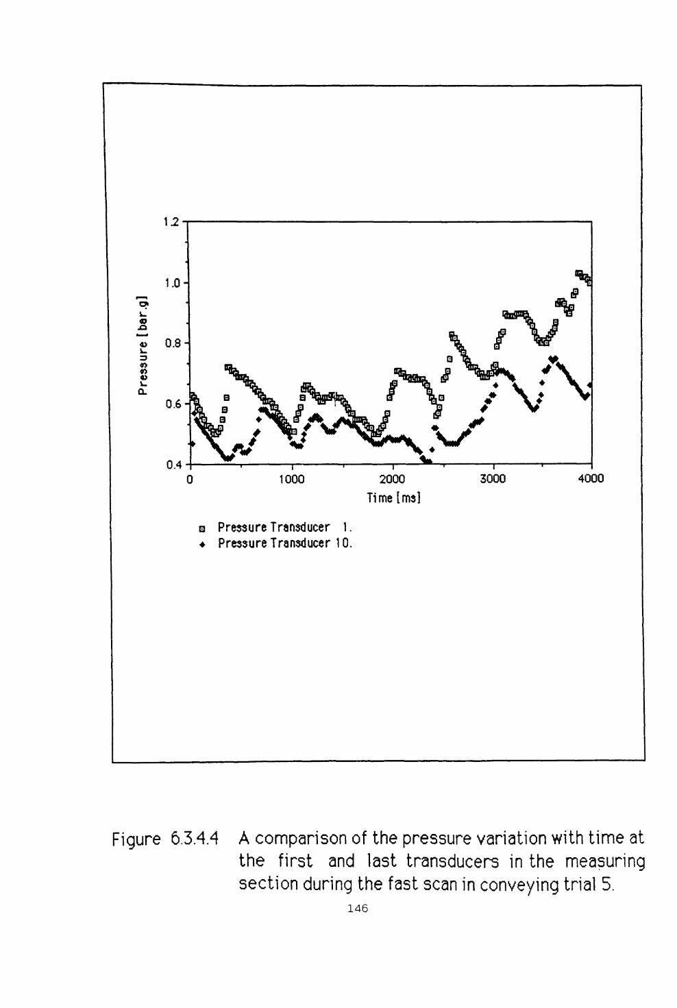
6.3.4 INTERPRETATION OF DATA FROM A FAST SCAN TEST


4.0 5.0
a P + a =0.82209- 4.1145E-2.X, p2 = 0.%7.
* P = 0.68640 -3.0612E-2.X, p2= 0.961.
P - (J = 0.55071 - 2.0079E-2.X, P2 = 0.914.


CD
<D


Key:
-4.3667, increase by 1.13 when Rs = 0.2.-4.5894, increase by 1.41 when Rs = 0.35.


ANALYSIS OF EXPERIMENTAL DATA