grid code - welcome to the central electricity board …ceb.intnet.mu/msdg/document/msdg grid code...
TRANSCRIPT

0 | P a g e
GRID CODE
MEDIUM SCALE DISTRIBUTED
GENERATION (MSDG)
Greater than 200kW but not exceeding 2MW
Version 2.1
December 2013
CENTRAL ELECTRICITY BOARD Royal Road Curepipe
Mauritius Tel No.: (230) 601 1100 Fax No.: (230) 601 1180

i | P a g e
Foreword
The purpose of this document is to assist the public to better understand the procedure
for application, the requirements of the Grid Code, the Feed-in-Tariffs and other related
issues regarding Medium Scale Distributed Generation (MSDG).
Any prospective applicant willing to take advantage of the Medium Scale Distributed
Generation (MSDG) Scheme is informed that:
I. Compliance to this Grid Code is mandatory
II. The provisions of the Electricity Act shall be adhered to.
III. This Grid Code will be reviewed and updated when the need arises.

ii | P a g e
TABLE OF CONTENTS
CHAPTER 1 Purpose of the Grid Code……………………………………………………....... 1
CHAPTER 2 Connecting Medium Scale Distributed Generation to the Grid…………… 2
CHAPTER 3 MSDG Interconnection Requirements and Safety Aspects………………… 4
3.1 Interconnection Facility Characteristics ...……………………………………… 4
3.2 22kV System Parameters…………………………………………………………. 4
3.3 MSDG High Voltage Switchgear………………………………………………... 4
3.4 MSDG Interconnection transformer…………………………………………….. 5
3.5 Earthing Arrangement……………………………………………………………. 5
3.6 Protection Requirements…………………………………………………………. 5
3.6.1 Interconnection protection scheme……………………………………… 6
3.6.2 Anti-Islanding protection………………………………………………… 6
3.6.3 Inter-tripping protection for MSDG of capacity greater than 500kW.. 7
3.6.4 Protection against relay malfunction……………………………………. 7
3.6.5 Protection Study…………………………………………………………... 7
3.7 Synchronising AC generators……………………………………………………. 7
3.8 Re-connection…………………………………………………………………….... 8
3.9 Uninterruptible Power Supply…………………………………………………... 8
3.10 Indication, Alarms and Instrumentation……………………………………….. 8
3.11 Communication Requirements…………………………………………………... 8
3.12 Metering…………………………………………………………………………….. 9
3.13 Safety, Isolation and Switching…………………………………………………... 9
3.13.1 Safety Procedures regarding the operation of High Voltage
Switchgear………………………………………………………………………….
9
3.13.2 Safety Concerns………………………………………………………….. 10
3.13.3 Electromagnetic emission/Immunity………………………………….. 11
3.13.4 Labels……………………………………………………………………... 11
3.14 Documentation……………………………………………………………………. 11
3.15 Information Plate…………………………………………………………………... 12
3.16 Electrical Contractor/Installer…………………………………………………….. 12
3.17 Standard and Regulation…………………………………………………………. 13
CHAPTER 4 Guarantee Operating Characteristic……………………………………………. 15
4.1 Fault Ride Through Requirements………………………………………………. 15
4.2 Frequency Response……………………………………………………………..... 15
4.3 Reactive Power Capability………………………………………………………… 16
4.4 Power Quality……………………………………………………………………… 17
4.4.1 Limitation of voltage flicker induced by the MSDG…………………. 17
4.4.2 Harmonics ………………………………………………………………... 17
4.4.3 Voltage step change…………………………………………………....... 17

iii | P a g e
4.4.4 Surge Withstand Capability……………………………………………. 18
4.4.5 Voltage and Current Unbalance……………………………………….. 18
4.5 Ramp Rate Limits………………………………………………………………….. 18
CHAPTER 5 Testing and Commissioning…………………………………………………….. 19
5.0 Introduction…………………………………………………………………………. 19
5.1 Testing of MSDG Facility………………………………………………………….. 19
5.2 Commissioning of electrical system…………………………………………….... 20
5.3 Power Quality………………………………………………………………………. 20
Annex 1 Abbreviations and Definitions…………………………………………………… 21
Annex 2 CEB Feed-In-Tariff………………………………………………………………… 23
Annex 3 CEB Fees……………………………………………………………………………. 24
Annex 4 Application Form………………………………………………………………….. 25
Annex 5 Certificate of Installation………………………………………………………...... 32
Annex 6 Certificate of Compliance…………………………………………………………. 33
Annex 7 22kV Switchgear Arrangement…………………………………………………... 34
Annex 8 Interconnection Facility Description…………………………………………….. 35
Annex 9 Interconnection Transformer Specifications……………………………………. 43
Annex 10 Mineral Insulating Oil for Transformers………………………………………... 48
Annex 11 Typical Medium Voltage Switchgear Panel and Protection Arrangement…. 50
Annex 12 Protection Specifications………………………………………………………….. 51
Annex 13 Communication Requirement……………………………………………………. 52
Annex 14 Typical 22kV Switchgear Room………………………………………………….. 54

1 | P a g e
CHAPTER 1 Purpose of the Grid Code
This Grid Code describes the technical criteria and requirements for the connection of
distributed generation unit (s) of capacity greater than 200 kW but not exceeding 2MW
to the CEB’s 22 kV distribution network.
The aggregate capacity of all medium-scale distributed generation (MSDG) facilities
that can be interconnected to a 22kV distributed feeder is termed as the hosting capacity
and is taken as 100% of the minimum load demand on that feeder.
The aggregate capacity of all MSDG facilities of capacity less than 200 kW that can be
interconnected to a 22kV distributed feeder is limited to 50 % of the hosting capacity of
that feeder.
The application for the interconnection of any MSDG facility to a 22kV distribution
feeder shall be considered provided that with the proposed MSDG facility, the
aggregate installed capacity of the MSDG facilities connected to the 22kV distribution
feeder does not exceed the hosting capacity of that feeder.
Notwithstanding the above limits, the feasibility to connect any MSDG to CEB 22 kV
distribution network will need to be confirmed by a system impact study which will be
conducted by the CEB on a case to case basis. In addition, the possibility of
interconnecting any MSDG facility with variable power output shall be subject to the
maximum amount of variable renewable energy-based power generation that can be
accommodated in the CEB’s power system while maintaining the system stability and
security not being exceeded with the proposed MSDG facility.
The Grid Code caters for the production of electricity by the following list of renewable
energy technologies (RETs):
1. Photovoltaic (PV)
2. Wind Turbine Generator (WTG)
3. Hydroelectric Generator
4. Biomass-based generator
2 | P a g e
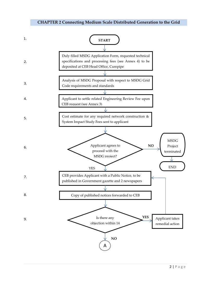
CHAPTER 2 Connecting Medium Scale Distributed Generation to the Grid
START
Analysis of MSDG Proposal with respect to MSDG Grid
Code requirements and standards
CEB provides Applicant with a Public Notice, to be
published in Government gazette and 2 newspapers
Copy of published notices forwarded to CEB
Is there any
objection within 14
days?
Applicant takes
remedial action
NO
YES
Duly filled MSDG Application Form, requested technical
specifications and processing fees (see Annex 4) to be
deposited at CEB Head Office, Curepipe
Cost estimate for any required network construction &
System Impact Study Fees sent to applicant
Applicant agrees to
proceed with the
MSDG project?
NO
MSDG
Project
terminated
YES END
1.
2.
3.
4.
5.
6.
7.
8.
9.
Applicant to settle related Engineering Review Fee upon
CEB request (see Annex 3)
A
3 | P a g e
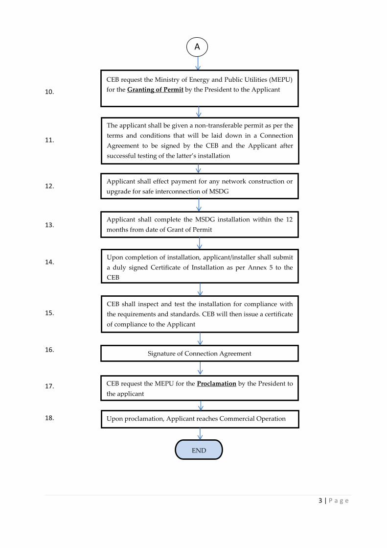
Applicant shall complete the MSDG installation within the 12
months from date of Grant of Permit
CEB shall inspect and test the installation for compliance with
the requirements and standards. CEB will then issue a certificate
of compliance to the Applicant
CEB request the MEPU for the Proclamation by the President to
the applicant
Upon proclamation, Applicant reaches Commercial Operation
END
Applicant shall effect payment for any network construction or
upgrade for safe interconnection of MSDG
The applicant shall be given a non-transferable permit as per the
terms and conditions that will be laid down in a Connection
Agreement to be signed by the CEB and the Applicant after
successful testing of the latter’s installation
Upon completion of installation, applicant/installer shall submit
a duly signed Certificate of Installation as per Annex 5 to the
CEB
Signature of Connection Agreement
11.
12.
13.
14.
15.
16.
17.
18.
CEB request the Ministry of Energy and Public Utilities (MEPU)
for the Granting of Permit by the President to the Applicant 10.
A
4 | P a g e
CHAPTER 3 MSDG Interconnection Requirements and Safety Aspects
3.1 Interconnection Facility Characteristics
The facility is described hereunder:
The facility is connected to CEB’s 22 kV network through a step up interconnection
transformer.
The “CEB Interconnection Facilities” which shall be the facilities required to
interconnect the Generation Facility to the CEB 22kV Distribution System located on
the CEB side of the Point of Common Coupling(PCC) /Point of Delivery,(A), as shown
in Annex 7.
The “MSDG Interconnection Facilities” which shall be the facilities required to
interconnect the Generation Facility to the CEB System located on the Generation
Facility side of the Point of Common Coupling (PCC)/ Point of Delivery (A) as shown
in Annex 7.
3.2 22kV System Parameters
The MSDG has the following design parameters. The MSDG has to function and protect itself
within the following range of the voltages, currents and frequencies existing in the CEB grid.
Service Voltage : 22 kV ± 6%
Emergency Voltage : 22 kV ± 10%
System Earthing : Effectively earthed/Non-effectively earthed
Frequency : 50 Hz ± 1.5%
Fault Level : 600 MVA
Operating Frequency : 47 Hz – 52Hz
3.3 MSDG High Voltage Switchgear
The switchgears shall be arranged as illustrated in Annex 7 - , consisting of CEB interconnection
facilities and MSDG interconnection facilities demarcated by a metallic barrier.
The applicant shall construct, install, test and commission the complete 22kV switchboard as
Annex 7 - , i.e. the CEB as well as the MSDG side. CEB will take ownership of its side after the
guarantee period.
The switchgear shall have the following characteristic:
Insulation rated voltage : 24 kV
Impulse test voltage 1, 2/50 µs : 125 kV peak
Rated short circuit capacity : 16 kA rms 1 sec
Electro-dynamic withstand : 40 kA peak
Busbar rating : 400 A
The detailed technical characteristics and responsibilities of the 22kV switchgear are given in
Annex 8. The 22kV switchgear shall be approved by the CEB prior to ordering.

5 | P a g e
3.4 MSDG Interconnection transformer
The MSDG interconnection transformer shall be of vector group Dyn11 (Delta on High Voltage
Side and Star on MSDG Side). The delta winding on the CEB side ensures that:
(i) The performance and sensitivity of the earth fault protection scheme at CEB substation
are not affected;
(ii) Triplen harmonics from the MSDG do no reach CEB’s network
(iii) The MSDG is provided some isolation from voltage sags due to single-line-to- ground
faults, allowing it to better ride through voltage sags.
The detailed specifications of the interconnection transformer are given in Annex 9. The
transformer shall be approved by the CEB prior to ordering.
3.5 Earthing Arrangement
The earthing arrangement of the generating plant must be designed to ensure compatibility
with Earthing system of the CEB distribution network. The actual earthing arrangements will
also be dependent on the number of generating units in use and the generators system
configuration and method of operation. The system earth connection shall have adequate
electrical and mechanical capability for the duty.
In the event that the Applicant wishes to operate independently and isolated from the CEB’s
system, the Applicant shall ensure that the electrical and protection systems of the facility are
designed to support such mode of operation. Safety of personnel and integrity of equipment
shall be guaranteed at all times during both parallel and isolated modes of operation.
Earthing systems shall be designed, installed, tested and maintained according to BS 7354 (Code
of Practice for Design of high voltage open terminal stations) and BS 7430 (Code of Practice for
Protective Earthing of electrical installations). Steps must be taken to prevent the appearance of
hazardous step and touch potential when earth faults occur on the 22 kV network. The 22 kV
earth electrodes and low voltage earth electrodes shall be adequately separated to prevent
dangerous earth potentials being transferred to the low voltage network.
3.6 Protection Requirements
The protection system, made up of two schemes, shall provide protection against fault
occurring on both the CEB’s network and the MSDG facility. The first protection scheme is to
provide protection against short circuit, earth faults and overloading conditions while the
second scheme is to prevent islanding operation of the CEB distribution feeder whereby the
MSDG is connected.
Both schemes shall incorporate a watchdog function that monitors relay status. Note that the
relays used shall be of modern numerical type and of utility grade. The two schemes are
detailed in the subsections 3.6.1 and 3.6.2 as interconnection protection scheme and anti-
islanding protection scheme respectively. A typical protection diagram for any MSDG is
illustrated in Annex 11.

6 | P a g e
In addition, the applicant must provide any additional protection functions necessary to
adequately protect all equipment and personnel. The settings of the additional protection
systems must be appropriately graded to prevent unnecessary trips during disturbances that
affect voltage and frequency on the CEB system.
3.6.1 Interconnection protection scheme
The Interconnection Protection Scheme must provide protection against short circuit, earth fault
and overloading conditions. This scheme shall consist of the following protection functions:
(i) instantaneous/time delayed overcurrent (50/51)
(ii) instantaneous/time delayed earth fault (50/51N)
(iii) Neutral Voltage Displacement (59N).
The characteristics for these protection functions are detailed in Annex 12. The protection shall
act on the line circuit breaker of the CEB Interconnection facilities(Circuit Breaker 1 (CB1) as
shown in Annex 7).
The settings for the protection functions 50/51 and 50/51N shall be determined by the applicant,
through a proper protection study, and submitted to CEB for approval. The setting for the
neutral voltage displacement is to be calculated as follows:
Table 1 Short circuit protection trip settings
Parameter Symbol Trip setting Clearance
Neutral Voltage Displacement (59N) NVD 1270V t0*+ 0.5s
*t0 is the maximum time delay for the CEB interconnecting feeder earth fault protection
Note: The protection requirement for the step-up transformer shall be determined by the
applicant.
3.6.2 Anti-islanding protection
The MSDG shall not supply power to the CEB’s network during any outages of the system. The
MSDG may only be operated during such outages to supply the applicant’s own load (isolated
generation) with a visibly open tie to the CEB’s network. The MSDG shall cease to energise the
CEB’s network within 0.5 seconds of the formation of an island. The following protection
functions and settings are required.
Over and under frequency (functions 81O and 81U)
Three-phase under-voltage and overvoltage (functions 27 and 59)
Rate of Change Of Frequency (ROCOF)
Voltage vector shift (VVS)

7 | P a g e
Table 2 Anti-islanding protection trip settings
Parameter Symbol Trip setting* Clearance
Overvoltage (27) U>> Vφ-φ + 7% 0.2s
Overvoltage (27) U> Vφ-φ + 5% 1.5s
Undervoltage (59) U< Vφ-φ – 6% 1.5s
Overfrequency (81O) f> 51.5 Hz 0.5 s
Underfrequency (81U) f< 47 Hz 0.5s
Loss of mains LoM 2.5 Hz/s
10 degrees
0.5s
0.5s
* The above trip settings are indicative and may be subject to change upon request of the CEB
for safe interconnection to the network.
The anti-islanding protection shall act on CB4 (LV interconnection circuit breaker) as shown in
the typical switchgear and protection arrangement in Annex 7.
For MSDG facilities of capacity equal to or greater than 500 kW, inter-tripping facility using
fibre optic cables will be required. This is detailed further in section 3.6.3.
3.6.3 Inter-tripping protection for MSDG of capacity equal to or greater than 500 kW
The inter-tripping scheme shall be designed such that tripping of the interconnecting feeder
circuit breaker in the CEB 22 kV substation results in the tripping of CB1 (see Annex 7). The
tripping of CEB’s 22 kV circuit breaker shall be a tripping due to protective relay action at CEB
22 kV substation level. Manual tripping of CB1 shall not cause tripping of corresponding circuit
breaker at CEB 22 kV substation.
3.6.4 Protection against relay malfunction
The watchdog function of the protection relay protection must issue an alarm and trip the
circuit breaker on which the protection relay normally acts in case the there is a malfunction.
For MSDG of capacity equal to or greater than 500 kW, this alarm signal shall be transmitted to
the interconnecting CEB substation via the fibre optic channel.
3.6.5 Protection study
For MSDG of capacity above 200 kW, the Applicant shall submit to CEB a complete protection
study report showing the following:
All protection calculations complete with graphs
Grading of the interconnection protection with CEB substation protection
Grading of the interconnection protection with MSDG protection scheme.
3.7 Synchronising AC generators
The MSDG shall provide and install automatic synchronizing. Check Synchronizing shall be
provided on all generator circuit breakers and any other circuit breakers, unless interlocked,
that are capable of connecting the MSDG plant to the CEB’s network. Check Synchronising
Interlocks shall include a feature such that circuit breaker closure via the Check Synchronising

8 | P a g e
Interlock is not possible if the permissive closing contact is closed prior to the circuit breaker
close signal being generated.
3.8 Re-connection
Following a protection initiated disconnection, the MSDG is to remain disconnected from the
network until the voltage and frequency at the supply terminals has remained within the
nominal limits for at least 3 minutes. Automatic reconnection is only allowed when
disconnection was due to operating parameters being outside the normal operating range stated
in Table 2, not if disconnection was caused by malfunctioning of any devices within the MSDG
installation.
3.9 Uninterruptible Power Supply
An uninterruptible power supply is required and it shall have adequate capacity to ensure that
the protection, measurement, control and communication systems operate without interruption
for a minimum duration of at least 30 minutes after loss of CEB power supply.
3.10 Indication, Alarms and Instrumentation
The alarm and trip facilities shall have local indication and, for MSDG equal to or greater than
500 kW, an additional set of potential-free contacts for onward transmission of the alarm/trip
signals to the CEB Substation.
The following panel instrumentation and other fittings are required in addition to other
standard equipment required or implied for the type of panel and scheme functionality:
a. Transducer fed voltmeter, ammeter, MW, MVAr, indicating import and export, and
appropriate test blocks for current and voltage circuits.
b. Suitable test facilities shall be provided for the secondary injection of current/relay
testing and for any other tests as reasonably required by CEB.
External indicator lamps shall be installed to indicate parallel operation of the MSDG facility
with CEB distribution network.
3.11 Communication Requirements
MSDG, of capacity equal to or greater than 500 kW , shall install communication equipment for
secured transfer of operating data and protection and control signals via fibre optics cables as
per Annex 13. The connection of the fibre optics to the RTU of the CEB‟s substation shall be
solely the responsibility of the CEB. Note that the Applicant shall bear the cost for the
installation of fibre optic cables from the MSDG plant to the corresponding substation.
Relevant information for the operation of the electrical system will be transmitted in real time to
the System Control through the RTU (remote terminal unit) available at the substation.
i. One-Way communication from the CEB Substation to the Generation Facility via the
fibre-optic link of:
- 22kV Circuit breaker status at the CEB substation(open/close);

9 | P a g e
ii. One – Way communication from the Generation Facility to the CEB Substation via the
fibre optics
- Cubicle 1 Circuit Breaker Status (open/close)
- Cubicle 4 Circuit Breaker Status (open/close)
- Alarms
- MW, MVAr
- Voltage level of the Generation Facility 22kV Busbar
iii. Remote control facilities shall be provided:
- Cubicle 1 circuit breaker open;
- Cubicle 1 circuit breaker close.
iv. Optical Fibre
The Optical fibre shall connect the generation facility and the 22kV feeder’s
Substation on which the MSDG is interconnected. The applicant shall bear the cost of
the procurement, installation and commissioning of the fibre optic link.
3.12 Metering
CEB Meters will have an accuracy class of 0.2 and shall measure the electrical energy delivered
to CEB by the MSDG as well as Import Energy imported by the MSDG from the CEB System. A
cubicle shall be ordered by CEB to house the CEB Meters.
The CEB metering circuits shall be totally separate from the MSDG metering circuits. This is to
be achieved through cabling directly from the metering current transformers (CTS) and voltage
transformers (VTs). CEB shall be fully responsible for the commissioning of the metering
circuits associated with CEB Meters, i.e. all pre-commissioning and final commissioning
involving cabling and other circuit verification, CT and VT checks and certification, functional
testing, as well as meter calibration, secondary injection and final documentation.
In addition the panel shall also provide for the accommodation of a digital 3-phase power
recorder/monitor with the remote communication capabilities, for power quality analysis,
energy management, data transfer and supervisory control needs.
The applicant may install at his own cost a backup meter capable of recording both the export
of electrical energy from Facility to the CEB Interconnection Facilities and the import of
electrical energy by the Facility from the CEB Interconnection Facilities. In this respect, an
optional cubicle housing the CTs and VTs will be required in the MSDG Interconnection
Facilities (see Annex 7).
3.13 Safety, Isolation and Switching
3.13.1 Safety Procedures regarding the operation of High Voltage Switchgear
In order to ensure the safety of personnel while operating or working on High Voltage
Switchgear installed for the purpose of supplying electricity to your premises, the following
requirements and procedures shall be adhered to:-

10 | P a g e
(a) To comply with Section 7(a) of the Occupational Safety, Health and Welfare Act of 2005
which states “Where the total power used or generated by the machinery installed at any
place of work exceeds 750 kilowatts, the employer shall employ a Registered Professional
Engineer to be in general charge of all such machinery”.
(b) The Applicant shall appoint and train competent person/s who shall be responsible for the
operation of the High Voltage Switchgear. He/they shall be fully conversant with the
electrical set-up, including that of the Switchgear belonging to CEB.
(c) An up-to-date schematic diagram of the switchgear set-up shall be displayed in the
switchgear room (See Annex 7).
(d) All switchgear panels shall be clearly numbered and labelled.
(e) Before any work can be performed on either side of the switchgear panel appropriate
switching operations shall be carried out by the respective competent person in the
presence of his respective counterpart. The competent person performing the operations
shall certify the operations carried out on the approved form and shall remit the original
to his counterpart, who may then proceed with the work in accordance with the Safety
Rules.
Note:
The person receiving the above information shall ensure that the switchgear involved
shall not be inadvertently operated by securing them by means of personal padlocks and
by affixing proper warning signs.
(f) In case of private generation, the client shall ensure that his system is completely isolated
from CEB system.
3.13.2 Safety Concerns
The applicant shall observe the following safety concerns which include:
(a) Persons must be warned that the installation includes an MSDG so that precautions can be
taken to avoid the risk of electric shock. Both the mains supply and the electric generator
must be securely isolated before electrical work is performed on any part of the
installation. Adequate labelling must be available to warn that the installation includes
another source of energy.
(b) Photovoltaic (PV) cells will produce an output whenever they are exposed to light, and
wind turbines are likely to produce an output whenever they are turning. Additional
precautions such as covering the PV cells or restraining the turbine from turning will be
necessary when working on those parts of the circuit close to the source of energy and
upstream of the means of isolation.
(c) The manufacturer or supplier of the MSDG is required to certify compliance with the
Electrical Equipment Safety Regulations and the Electromagnetic Compatibility
Regulations. The MSDG will be CE marked or tested by equivalent accredited testing
11 | P a g e
agencies to confirm this. This should ensure that the MSDG is satisfactory in a domestic
installation in terms of the power factor, generation of harmonics and voltage
disturbances arising from starting current and synchronisation.
(d) CEB personnel must be warned of the safety procedures pertaining to switching operation
applicable to the MSDG. These procedures must clearly be displayed and visible at the
MSDG site.
3.13.3 Electromagnetic emission/Immunity
The MSDG shall comply with the requirements of the EMC Directive and in particular the
product family emission standards.
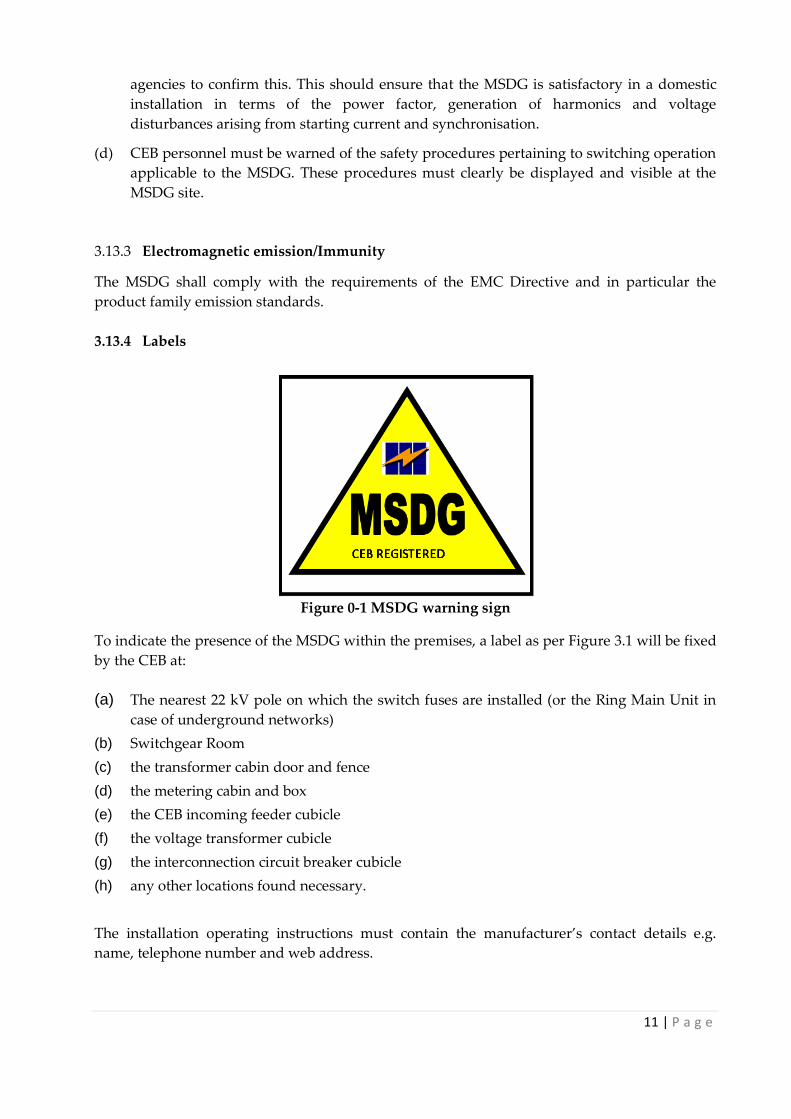
3.13.4 Labels
Figure 0-1 MSDG warning sign
To indicate the presence of the MSDG within the premises, a label as per Figure 3.1 will be fixed
by the CEB at:
(a) The nearest 22 kV pole on which the switch fuses are installed (or the Ring Main Unit in
case of underground networks)
(b) Switchgear Room
(c) the transformer cabin door and fence
(d) the metering cabin and box
(e) the CEB incoming feeder cubicle
(f) the voltage transformer cubicle
(g) the interconnection circuit breaker cubicle
(h) any other locations found necessary.
The installation operating instructions must contain the manufacturer’s contact details e.g.
name, telephone number and web address.

12 | P a g e
3.14 Documentation
Up-to-date information must be displayed at the MSDG as follows:
(a) A circuit diagram showing the relationship between the MSDG and the CEB’s incoming
feeder as shown in Annex 7 - . This diagram is also required to show by whom the
generator is owned and maintained.
(b) A summary of the interconnection and anti-islanding protection settings. The Annex 11 - is
an example of the type of circuit diagram that needs to be displayed.
(c) Switching operation at the MSDG facility
(d) In addition the maintenance requirements and maintenance services available shall be
documented.
(e) The applicant shall keep a certificate signed by the maintenance contractor containing at
least the following:
A statement confirming that the solar PV system/wind turbine/hydro, switchgear
and interconnection transformer meets the requirements of this standard.
Client’s name and address.
Site address (if different).
Contractors name, address etc.
List of key components installed.
Estimation of system performance
3.15 Information plate
The following information shall appear on the information plate:
(a) manufacturer’s name or trade mark;
(b) type designation or identification number, or any other means of identification making
it possible to obtain relevant information from the manufacturer;
(c) rated power;
(d) nominal voltage;
(e) nominal frequency,
(f) phases;
(g) power factor.
3.16 Electrical contractor / Installer
The MSDG shall be installed in accordance with the instructions issued by the manufacturer.
In designing a connection for any MSDG, the electrical contractor /installer must consider all
the issues that would need to be covered for a conventional final circuit, including:
the maximum demand (and the generator output);
the type of earthing arrangement;
the nature of the supply;
external influences;

13 | P a g e
compatibility, maintainability and accessibility;
protection against electric shock;
protection against thermal effects;
protection against overcurrent;
isolation and switching;
selection and installation issues.
The installer must affix a label clearly indicating the next scheduled maintenance of the
installations and inform the CEB, who will add the information to the MSDG-register.
The installer must be skilled in the field of MSDG installations and possess an approved
certificate.
3.17 Standard and Regulations
All electrical apparatus, materials and wiring supplied shall comply with the Electricity Act,
the Central Electricity Board Act, Electricity Regulations, this code and the following
standards:
EN 50380 Datasheet and nameplate information of photovoltaic module.
EN 50438 Requirements for the connection of micro-generators in parallel with public
low-voltage distribution networks
EN 50521 Connectors for photovoltaic systems - Safety.
EN 50524 Data sheet and name plate for photovoltaic inverters
IEC 60068-2 Environmental testing of specimen to withstand specific severities of
repetitive and non- repetitive nature
IEC 60228 Conductors of Insulated Cables
IEC 60364-1 Electrical installations of buildings - Part 1: Scope, object and fundamental
principles
IEC 60364-5-54 Electrical installations of buildings. Part 5: Selection and erection of
electrical equipment. Chapter 54: Earthing arrangements and protective
conductors
IEC 60364-5-55 Electrical installations of buildings
IEC 60502-1
Power Cables with extruded insulation and their accessories for rated
voltages from 1 kV (Um – 1.2 kV) up to 30 kV (Um = 36 kV)
Part 1 - Cables for rated voltages for 1 kV (Um=1.2 kV) and 3
IEC 60664-1 Insulation coordination for equipment within low-voltage systems – Part 1:
Principles, requirements and tests
IEC 60904-1 Photovoltaic devices: Part 1 Measurement of Photovoltaic current-voltage
characteristics
IEC 60909-1 Short circuit calculation in three-phase ac systems.
IEC 60947 Connectors for photovoltaic systems - Safety.
IEC 61000-3-3
Limits – Limitation of voltage changes, voltage fluctuations and flicker in
public low-voltage supply systems, for equipment with rated current ≤ 16 A
per phase and not subject to conditional connection
IEC 61000-3-7 Assessment of emission limits for the connection of the connection of
fluctuating installations to MV, HV and EHV power systems.
14 | P a g e
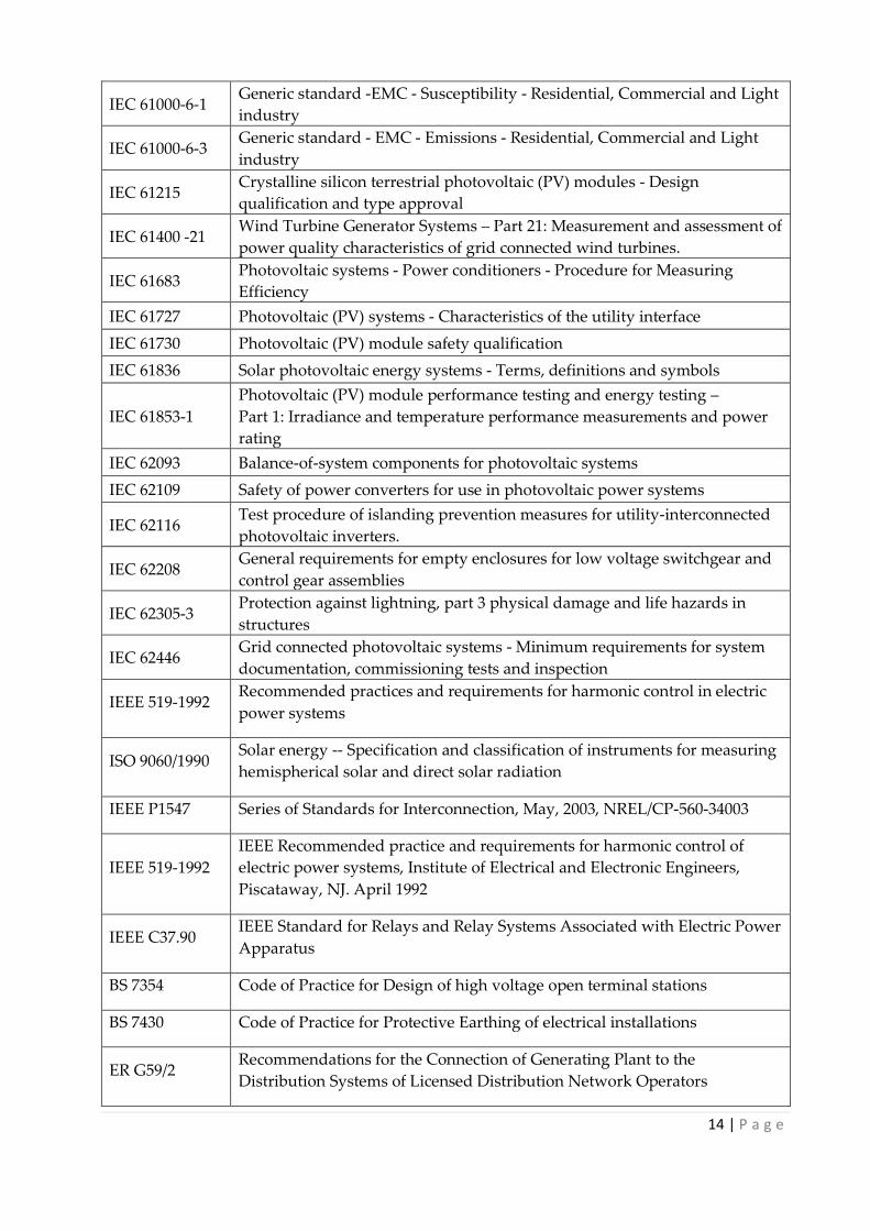
IEC 61000-6-1 Generic standard -EMC - Susceptibility - Residential, Commercial and Light
industry
IEC 61000-6-3 Generic standard - EMC - Emissions - Residential, Commercial and Light
industry
IEC 61215 Crystalline silicon terrestrial photovoltaic (PV) modules - Design
qualification and type approval
IEC 61400 -21 Wind Turbine Generator Systems – Part 21: Measurement and assessment of
power quality characteristics of grid connected wind turbines.
IEC 61683 Photovoltaic systems - Power conditioners - Procedure for Measuring
Efficiency
IEC 61727 Photovoltaic (PV) systems - Characteristics of the utility interface
IEC 61730 Photovoltaic (PV) module safety qualification
IEC 61836 Solar photovoltaic energy systems - Terms, definitions and symbols
IEC 61853-1
Photovoltaic (PV) module performance testing and energy testing –
Part 1: Irradiance and temperature performance measurements and power
rating
IEC 62093 Balance-of-system components for photovoltaic systems
IEC 62109 Safety of power converters for use in photovoltaic power systems
IEC 62116 Test procedure of islanding prevention measures for utility-interconnected
photovoltaic inverters.
IEC 62208 General requirements for empty enclosures for low voltage switchgear and
control gear assemblies
IEC 62305-3 Protection against lightning, part 3 physical damage and life hazards in
structures
IEC 62446 Grid connected photovoltaic systems - Minimum requirements for system
documentation, commissioning tests and inspection
IEEE 519-1992 Recommended practices and requirements for harmonic control in electric
power systems
ISO 9060/1990 Solar energy -- Specification and classification of instruments for measuring
hemispherical solar and direct solar radiation
IEEE P1547 Series of Standards for Interconnection, May, 2003, NREL/CP-560-34003
IEEE 519-1992
IEEE Recommended practice and requirements for harmonic control of
electric power systems, Institute of Electrical and Electronic Engineers,
Piscataway, NJ. April 1992
IEEE C37.90 IEEE Standard for Relays and Relay Systems Associated with Electric Power
Apparatus
BS 7354 Code of Practice for Design of high voltage open terminal stations
BS 7430 Code of Practice for Protective Earthing of electrical installations
ER G59/2 Recommendations for the Connection of Generating Plant to the
Distribution Systems of Licensed Distribution Network Operators
15 | P a g e
CHAPTER 4: Guarantee Operating Characteristic
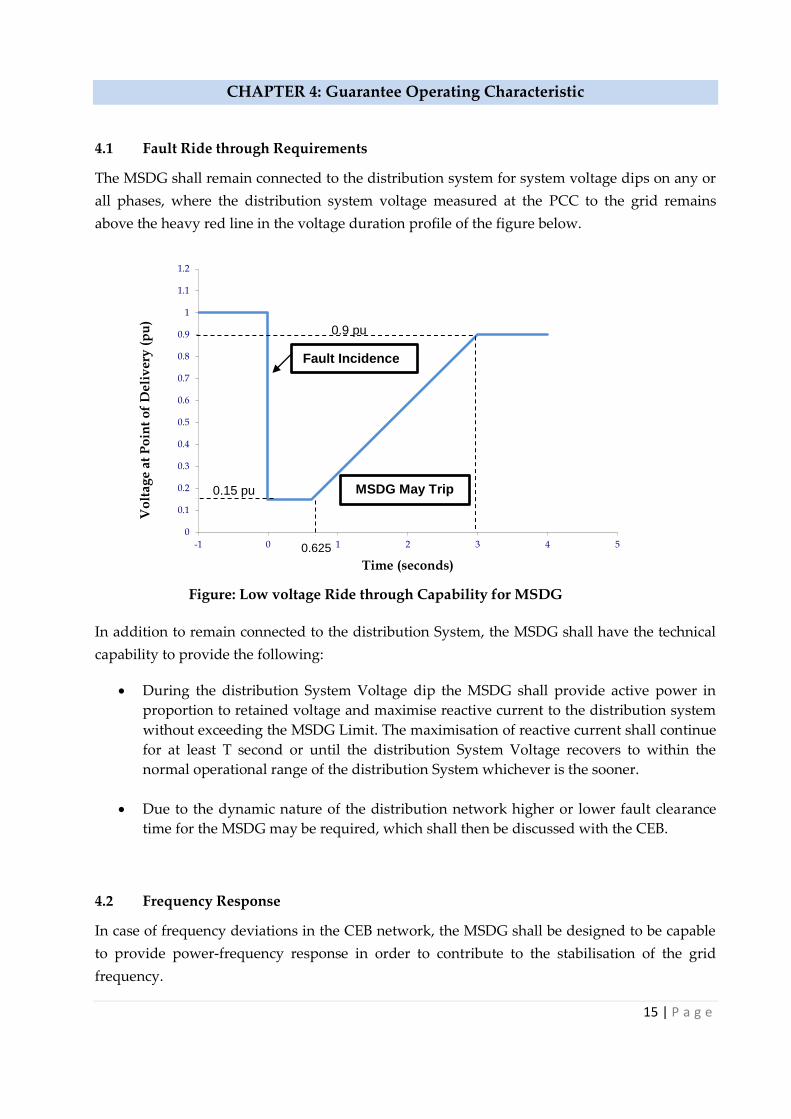
4.1 Fault Ride through Requirements
The MSDG shall remain connected to the distribution system for system voltage dips on any or
all phases, where the distribution system voltage measured at the PCC to the grid remains
above the heavy red line in the voltage duration profile of the figure below.
In addition to remain connected to the distribution System, the MSDG shall have the technical
capability to provide the following:
During the distribution System Voltage dip the MSDG shall provide active power in
proportion to retained voltage and maximise reactive current to the distribution system
without exceeding the MSDG Limit. The maximisation of reactive current shall continue
for at least T second or until the distribution System Voltage recovers to within the
normal operational range of the distribution System whichever is the sooner.
Due to the dynamic nature of the distribution network higher or lower fault clearance
time for the MSDG may be required, which shall then be discussed with the CEB.
4.2 Frequency Response
In case of frequency deviations in the CEB network, the MSDG shall be designed to be capable
to provide power-frequency response in order to contribute to the stabilisation of the grid
frequency.
0
0.1
0.2
0.3
0.4
0.5
0.6
0.7
0.8
0.9
1
1.1
1.2
-1 0 1 2 3 4 5
Vo
lta
ge
at
Po
int
of
De
liv
ery
(p
u)
Time (seconds)
0.9 pu
0.15 pu
0.625
Fault Incidence
MSDG May Trip
Figure: Low voltage Ride through Capability for MSDG
16 | P a g e
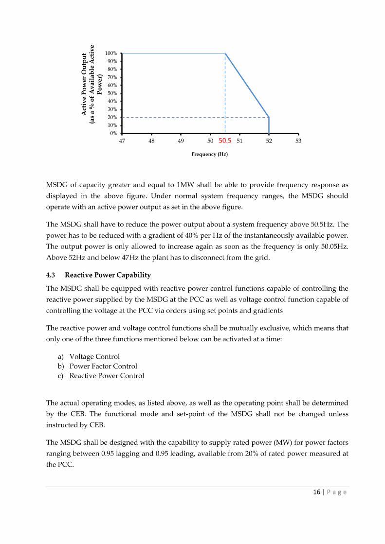
MSDG of capacity greater and equal to 1MW shall be able to provide frequency response as
displayed in the above figure. Under normal system frequency ranges, the MSDG should
operate with an active power output as set in the above figure.
The MSDG shall have to reduce the power output about a system frequency above 50.5Hz. The
power has to be reduced with a gradient of 40% per Hz of the instantaneously available power.
The output power is only allowed to increase again as soon as the frequency is only 50.05Hz.
Above 52Hz and below 47Hz the plant has to disconnect from the grid.
4.3 Reactive Power Capability
The MSDG shall be equipped with reactive power control functions capable of controlling the
reactive power supplied by the MSDG at the PCC as well as voltage control function capable of
controlling the voltage at the PCC via orders using set points and gradients
The reactive power and voltage control functions shall be mutually exclusive, which means that
only one of the three functions mentioned below can be activated at a time:
a) Voltage Control
b) Power Factor Control
c) Reactive Power Control
The actual operating modes, as listed above, as well as the operating point shall be determined
by the CEB. The functional mode and set-point of the MSDG shall not be changed unless
instructed by CEB.
The MSDG shall be designed with the capability to supply rated power (MW) for power factors
ranging between 0.95 lagging and 0.95 leading, available from 20% of rated power measured at
the PCC.
0%
10%
20%
30%
40%
50%
60%
70%
80%
90%
100%
47 48 49 50 51 52 53
Act
ive
Po
we
r O
utp
ut
(a
s a
% o
f A
va
ila
ble
Act
ive
P
ow
er)
Frequency (Hz)
50.5

17 | P a g e
4.4 Power Quality
The MSDG facilities and equipment shall not cause excessive voltage excursions nor cause the
voltage to drop below or rise above the range maintained by CEB. The MSDG facility and
equipment shall not introduce excessive distortion to the sinusoidal voltage or current waves.
4.4.1 Limitation of voltage flicker induced by the MSDG
The MSDG installation shall not cause abnormal flicker beyond the limits defined by the
“Maximum Borderline of Irritation Curve” specified in the IEEE 519-1992.
4.4.2 Harmonics
The total harmonic distortion will depend on the injected harmonic current and the system
impedance seen from the PCC.
The MSDG system output should have low current-distortion levels to ensure that no adverse
effects are caused to other equipment connected to the utility system. The MSDG system
electrical output at the PCC should comply with Clause 10 of IEEE Std. 519-1992 and should be
used to define the acceptable distortion levels for PV systems connected to a utility. The key
requirements of this clause are summarized in the following:
(a) Total harmonic current distortion (Total demand distortion, TDD) shall be less than
5% of the fundamental frequency current at rated current output.
(b) Each individual harmonic shall be limited to the percentages listed in Table 3. The
limits in Table 3 are a percentage of the fundamental frequency current at rated
current output.
(c) Even harmonics in these ranges shall be <25% of the odd harmonic limits listed.
Table 3 Distortion limits as recommended in IEEE Std. 519-1992
4.4.3 Voltage step change
The process of starting a medium scale distributed generation (MSDG) can sometimes cause
step changes in voltage levels in the distribution network. These step changes are caused by
inrush currents, which may occur when transformers or induction generators are energised
Odd Harmonics Maximum Harmonic Current Distortion
3rd -9th 4.0%
11th -15th 2.0%
17th -21st 1.5%
23rd -33rd 0.6%
Above the 33rd 0.3%
18 | P a g e
from the network. Step voltage changes will also occur whenever a loaded generator is
suddenly disconnected from the network due to faults or other occurrences.
Step voltage changes caused by the connection and disconnection of generating plants at the
distribution level should not exceed +/- 3% for infrequent planned switching events or outages
and +/-6% of the nominal voltage of 22kV for unplanned outages such as faults.
4.4.4 Surge Withstand Capability
The interconnection system shall have a surge withstand capability, both oscillatory and fast
transient, in accordance with IEC 62305-3. The design of control systems shall meet or exceed
the surge withstand capability requirements of IEEE C37.90.
4.4.5 Voltage and Current Unbalance
The contribution to the level of unbalance of the voltage at the point of common coupling of
any installation with generation should be less than or equal to 1%.
4.5 Ramp Rate Limits
MSDG greater than and equal to 1MW shall have ramp up/down capability for all ranges of
operation including positive ramp rate during start up, positive ramp rate only during normal
operation and negative ramp rate during shut down of the MSDG facility. The MSDG shall
have two ramp rates
a) 10 minute maximum ramp rate (Installed Capacity divided by 1.5)
b) 1 minute maximum ramp rate (Installed Capacity divided by 5)
The ramp rate averaged over one minute should not exceed 3 times the average ramp rate over
10 minutes. The ramp rate settings shall be approved by CEB prior to testing and
commissioning of the system on the network. For any subsequent change, a minimum of two
weeks’ notice shall be given. Implementation by the Promoter shall be done within two weeks
of formal request.

19 | P a g e
CHAPTER 5: Testing and Commissioning
5.0 Introduction
The Applicant shall notify the CEB in advance of the testing and commissioning as per IEC
norms. The Applicant shall keep written records of test results and protection settings. The
Applicant shall regularly maintain the protection systems in accordance with good electrical
industry practice.
The interconnection protection of the MSDG shall be regularly tested by the owner. In addition,
it may be necessary to perform tests on ad-hoc basis for purposes such as ascertaining level of
harmonic emissions, voltage rise, protection operation in the context of system changes, fault
investigation and protection changes etc.
5.1 Testing and Commissioning
The Applicant shall submit appropriate testing and commissioning procedures and plans as per
IEC norms for the MSDG Facility to CEB for approval at least 3 (three) months prior to the
Schedule Commercial Operation Date of the MSDG Facility.
5.1.1 Testing Phase
A number of typical tests among others for PV and WTG MSDG Facility have been identified
by the CEB in this Grid Code. However it is the responsibility of the MSDG owner to ensure
that all required tests are performed to ensure compliance with this grid code. The tests
identified are as follows:
a) Photovoltaic facility
Earthing continuity of array frame to earth and connection to main earthing
terminal
Polarity of each module string
PV string Open-Circuit Voltage (Voc) Test;
PV Short Circuit current (Isc) Test;
PV array insulation Test;
Operational Test PV string current;
Functional Test;
Irradiance Test;
Insulation resistance Testing; and
Performance verifications;
b) Wind TG Facility
6 hour test run with the generator connected to the grid
Demonstration of WTG vibration level below acceptable level.
Test of trip function when WTG is generation and grid loss occurs
Test of over speed trip of each WTG
Test of yaw drives
Functional test

20 | P a g e
Performance verification
5.1.2 Commissioning Phase
The Commissioning tests shall be performed in the presence of the CEB. CEB reserve the right
to request the applicant to perform additional tests which CEB may find necessary to ensure
integrity of its network.
The commissioning of the electrical system shall include at least the followings:
a) Demonstration of satisfactory operation of power measurement
equipment
b) Functional tests of the relay protection and verification of settings
c) Demonstration of satisfactory operation of internal reticulation
d) Demonstration of satisfactory operation of the transformer cooling
equipment in pooling substation.
e) Pressure tests on 22kV switchgear
f) Reactive Power Capability.
g) Power Quality Test as per IEC 61400-21
h) Anti-islanding
i) Test of the facility to withstand step load change
5.3 Power Quality
CEB will perform tests to ensure that the facility is compliant with Section 4.4 of this Grid Code.

21 | P a g e
Annex 1 - Abbreviations and Definitions
“AC” means Alternating Current;
“Applicant” means a producer of electricity through an MSDG installation;
“CEB” means the Central Electricity Board;
“Circuit breaker” means a switching device capable of making, carrying, and
breaking currents under normal circuit conditions and also making, carrying for a
specified time, and breaking currents under specified abnormal conditions such as
those of short circuit;
“DC” means Direct Current;
“DG” means Distributed Generation
“Distributed generation” means electric generation facilities connected to the Utility
network at the PCC;
“Flicker” means a variation of input voltage sufficient in duration to allow visual
observation of a change in electric light source intensity;
“Fault” means a physical condition that causes a device, a component, or an element
to fail to perform in a required manner, for example a short-circuit, a broken wire, an
intermittent connection;
“Frequency” means the number of complete cycles of sinusoidal variations per unit
time;
“Grid” means CEB’s network that brings electricity from power stations to
consumers”
“THD” means Total Harmonic Distortion
“Harmonic distortion” means continuous distortion of the normal sine wave;
typically caused by nonlinear loads or by inverters, measured in Total Harmonic
Distortion (THD);
“Islanding” means a condition in which a portion of the CEB’s network is energised
by one or more MSDGs through their PCC(s) while electrically separated from the
rest of the system;
“Isolated Generation” means a condition where the electrical path at the PCC is open
and the MSDG continues to energise local loads;
“kV” means kilovolt;
“kVA” means Kilovolt Ampere
“kW” means Kilo Watt (1,000 W = 1,000 J/s);
“kWh” means Kilowatt hour (1,000 watt hours);
22 | P a g e
“LV” means Low Voltage (refers to systems normally operating at a voltage not
exceeding 1000 volts A.C. or 1500 volt D.C.);
“HT” means High Tension (refers to systems normally operating at a voltage
exceeding 1000 volts A.C. or 1500 volt D.C.)
“HV” means High Voltage (see “HT”)
“MW” means megawatt (1,000,000 W = 1,000,000 J/s);
“Parallel operation” means a condition where the MSDG is operating while
connected to CEB’s network;
“PCC” means point of common coupling;
“Point of Common Coupling (PCC)” means the point at which an MSDG is
connected to the CEB’s network
“Power factor” means ratio of real to total apparent power (kW/kVA) expressed as a
decimal or percentage;
“Producer” means a producer of electricity through any MSDG installation or the
owner thereof;
“PV” means photovoltaic;
“RE” means renewable energy;
“MSDG” means Medium Scale Distributed Generation greater than 200 kW up to
2000 kW
“SWC” means Surge Withstand Capability, the immunity of this equipment to fast
and repetitive electrical transients;

23 | P a g e
Annex 2 - CEB Feed-In-Tariff
Tariff, if applicable, will be determined subject to discussion with the CEB. However for MSDG
projects designed to meet their own local consumption, a charge may be applicable.

24 | P a g e
Annex 3 - CEB Fees
Interconnection facility and cost
The MSDG will be connected to CEB 22kV network through a Medium Voltage switchgear and
metered on the medium-voltage side.
In addition, the applicant shall bear fees for processing applications and preparation of cost
estimate for network construction or modification as shown below.
Fees for processing of application:
Processing of the Application Rs 375
Connection Fees:
Connection for Three Phase Rs 3,000
Engineering Review/ Distribution Study
Preparation of estimate for network modification Rs 25,000
Revision of Estimate Rs 3,000
System Impact Study Fee Rs **
Network construction / modification
The cost for network construction or modification will be determined after carrying out the
engineering review.
** A system impact study will be performed for all MSDG projects to ensure safe integration on the
network. The applicable fee will be determined on a case-to-case basis.
25 | P a g e
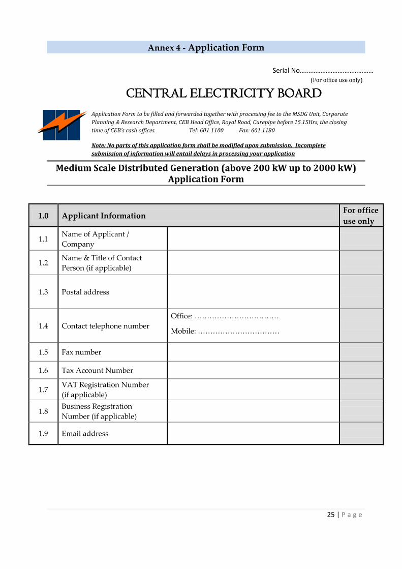
Serial No….………………………………… (For office use only)
Annex 4 - Application Form
Medium Scale Distributed Generation (above 200 kW up to 2000 kW) Application Form
1.0 Applicant Information For office
use only
1.1 Name of Applicant /
Company
1.2 Name & Title of Contact
Person (if applicable)
1.3 Postal address
1.4 Contact telephone number
Office: …………………………….
Mobile: ……………………………
1.5 Fax number
1.6 Tax Account Number
1.7 VAT Registration Number
(if applicable)
1.8 Business Registration
Number (if applicable)
1.9 Email address
CENTRAL ELECTRICITY BOARD
Application Form to be filled and forwarded together with processing fee to the MSDG Unit, Corporate
Planning & Research Department, CEB Head Office, Royal Road, Curepipe before 15.15Hrs, the closing
time of CEB’s cash offices. Tel: 601 1100 Fax: 601 1180
Note: No parts of this application form shall be modified upon submission. Incomplete
submission of information will entail delays in processing your application
26 | P a g e
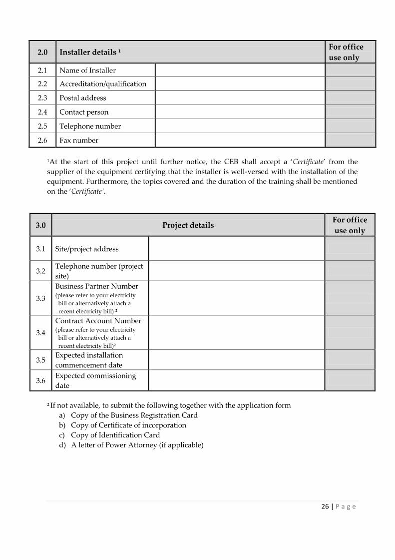
2.0 Installer details 1 For office
use only
2.1 Name of Installer
2.2 Accreditation/qualification
2.3 Postal address
2.4 Contact person
2.5 Telephone number
2.6 Fax number
1At the start of this project until further notice, the CEB shall accept a ‘Certificate’ from the
supplier of the equipment certifying that the installer is well-versed with the installation of the
equipment. Furthermore, the topics covered and the duration of the training shall be mentioned
on the ‘Certificate’.
3.0 Project details For office
use only
3.1 Site/project address
3.2 Telephone number (project
site)
3.3
Business Partner Number (please refer to your electricity
bill or alternatively attach a
recent electricity bill) 2
3.4
Contract Account Number (please refer to your electricity
bill or alternatively attach a
recent electricity bill)2
3.5 Expected installation
commencement date
3.6 Expected commissioning
date
2 If not available, to submit the following together with the application form
a) Copy of the Business Registration Card
b) Copy of Certificate of incorporation
c) Copy of Identification Card
d) A letter of Power Attorney (if applicable)
27 | P a g e
4.0 MSDG details For office
use only
4.1 MSDG location within the installation To submit site and location plan
4.2 Type of RE technology
(photovoltaic/ hydro/ wind/biomass) To submit manufacturer data sheet
4.3
Type of generator
(synchronous/induction/ inverter-
based)
To submit manufacturer data sheet
4.4
Total number of MSDG units to be
installed under this project, to include
MSDG installation capacity in kW and
kVA
No. of Units: ………………..of ………kW
each
Total kW: ……………
Total kVA: ………….
4.5 Expected annual generation (kWh)
4.6 Any other SSDG/MSDG on installation
site (Yes/No)
If yes, to specify
Total kW : …………… Total kVA :
……………
5.0 Other information to be submitted For office
use only
5.1 Type test certificate of RE technology (photovoltaic/ hydro/ wind/biomass)
thereon including the following information:
Manufacturer and model type
Country of origin
Standard of compliance 3
Contact details of Certifying Laboratory– telephone number, web address
etc
5.2 Type test certificate of generator (synchronous/induction/ inverter-based) thereon
including the following information:
Manufacturer and model type
Country of origin
MSDG current rating (A), voltage rating (V), rated power factor and
frequency (Hz)
Maximum peak short circuit current (A)
Standard of compliance 3
Contact details of Certifying Laboratory – telephone number, web address
etc

28 | P a g e
Other information to be submitted (Cont.) For office
use only
5.3
Copy of system circuit diagram (single line diagram) within the installation
including the proposed grid connection and the associated metering points/
supply points
5.4 Single Line Diagram illustrating the protection schemes of the MSDG
(including relay positioning, protection functions and related circuit breaker)
5.5 Earthing arrangements (Single Line Diagram)
5.6 Site layout plan showing location of MSDGs and other major electrical
equipment installed including the Joint Use Facility –
5.7 Procedures for the isolation of MSDG installation
5.8
Complete sequence of operations:
(a) In normal mode
(b) Upon loss of mains (operation of MSDG protections; changeover
sequence; starting of standby sets; interlocking between changeover &
MSDG; where is decoupling performed)
(c) On restoration of grid power
5.9 Complete set of specifications of the equipment to be used in the Joint Use
Facility (busbar, isolators, circuit breakers, enclosure, etc…)
3 All MSDGs to submit certificate of compliance with the Electrical Equipment Safety
Regulations and the Electromagnetic Compatibility Regulations (CE Marked). PV
installations to submit certificates that the panels are to IEC 61215 for crystalline silicon and
IEC 61646 for thin film silicon. Wind installations to submit certificates that the wind turbine
is as per IEC 61400-2.

29 | P a g e
MSDG Guaranteed Particulars
(All information given hereunder should be substantiated by documents from the Manufacturer)
6.0 MSDG Guaranteed Particulars
Item.
No. Protection Parameters Settings
Required settings To specify System settings
Trip Setting Clearance
Time
Trip
Setting
Clearance
Time
Trip
Indication
Provided
6.1 Over Voltage (22kV + 10 %) 24.2 kV 0,2 s
6.2 Over Voltage (22kV + 6 %) 23.3k V 1,5 s
6.3 Under Voltage (22kV – 6 %) 20.7 V 1,5 s
6.4 Over Frequency (50 Hz + 2 %) 51 Hz 0,5 s
6.5 Under Frequency (50 Hz - 6 %) 47 Hz 0,5 s
6.6 Loss of Mains(df/dt - Vector
shift)
2.5 Hz / s
10 degrees 0,5 s
6.7 Islanding Detection Yes
6.8 Isolated Generation possible Yes / No
6.9 Reconnection Time 3 minutes
6.10 Rated AC output Current per phase To specify
6.11 Total Harmonics Distortion (Voltage) at PCC To specify
6.12 Total Harmonics Distortion (Current) at PCC To specify
6.13 Surge Withstand Capability (kV) To specify
6.14 Power Factor (leading & lagging) 0.95
6.15 Will Production Meter be installed? Yes / No
6.16 Will a Backup Meter be installed? Yes / No
6.17 Will Battery Storage be Installed?
If yes, to specify purpose. Yes / No
6.18 Fault-ride through capability
(in case of inverter-based) Yes / No
6.19 Documentation on relays to be used on low-
voltage side To submit
6.20 Likely load profile and generation profile To submit
6.21 Is inverter equipped with Maximum Power
Point Tracking (MPPT) (in case of inverter) Yes / No
6.22
Will a technical staff be available on a round
the clock basis with whom CEB can
communicate whenever required?
Yes / No

30 | P a g e
7.0 Interconnection Transformer Details
Item. No. Parameter Value
7.1 Rated voltage (HV/LV)
7.2 Rated Power (MVA rating)
7.3 Positive sequence impedance in %
7.4 Zero sequence impedance in %
7.5 Positive sequence losses in kW
7.6 No load losses in kW
7.7 No load current in %
9.0 Synchronous Generator Details
Item. No. Parameter Value
9.1 Nominal apparent power (MVA)
9.2 Nominal voltage (kV)
9.3 Power factor
9.4 Connection (Star or delta)
9.5 Direct axis synchronous reactance, xd (p.u)
9.6 Quadrature axis synchronous reactance, xq (p.u)
9.7 Zero sequence reactance, x0 (p.u)
9.8 Zero sequence resistance, r0 (p.u)
9.9 Negative sequence reactance, x2 (p.u)
9.10 Negative sequence resistance, r2 (p.u)
9.11 Transient reactance, xd’ (p.u)
9.12 Sub transient reactance (saturated value), xd’’ sat (p.u)
9.13 Stator resistance, ratio X/R
9.14 Inertia constant, H
9.15 Time constant, T’d
9.16 Time constant, T’’d
8.0 Inverter details ( The table must be filled in for each type of inverter)
Item. No. Parameter Value
8.1 Make
8.2 Model
8.3 Rated Apparent Power /kVA
8.4 Number of inverters
8.5 Rated output voltage (V)
8.6 Power factor range of operation
8.7 Inverter efficiency at full load (%)
8.8 Total Harmonic Distortion (THD) (%)

31 | P a g e
11.0 Declaration – to be completed by applicant*
Comments (use separate
sheet if necessary)
(a) I declare that this installation will be designed to comply with the requirements of CEB.
(b) I declare that I shall adhere to the Grant of Permit and Proclamation procedures for
MSDG installation as shown in Chapter 2
(c) I declare that I have been informed by the CEB that
1) The tariff, if applicable, for the energy sold to the CEB by the proposed MSDG
installation will be determined subject to discussion with the CEB.
2) A charge may be applicable if the MSDG project has been designed to meet my
own local consumption.
Name (BLOCK
LETTERS):
Signature:
Date:
* This field is mandatory to complete before submission.
10 Induction Generator Details
Item. No Parameter Value
10.1 Nominal apparent power (MVA)
10.2 Nominal voltage (kV)
10.3 Rated apparent power (kVA)
10.4 Nominal frequency (Hz)
10.5 No. of pole pairs
10.6 Connection (Star or delta)
10.7 Rotor (single or double cage)
10.8 Stator resistance, Rs (p.u.)
10.9 Stator reactance, Xs (p.u.)
10.10 Magnetising reactance, Xm (p.u.)
10.11 Rotor leakage reactance, Xl (p.u.)
10.12 Operating Rotor resistance, RrA (p.u.)
10.13 Operating Rotor reactance, XrA (p.u.)
10.14 Starting cage rotor resistance, RrB (p.u.)
10.15 Starting cage rotor reactance, XrB (p.u.)

32 | P a g e
Annex 5 - Certificate of Installation
Applicant/installer to submit duly signed certificate (as shown below) to the CEB.
CERTIFICATE OF INSTALLATION
I hereby certify that the installation of the MSDG of capacity …………….kW, situated at
(address) for (name of Applicant) has been done as per the requirements of the GRID CODE
FOR MEDIUM SCALE DISTRIBUTED GENERATION (MSDG) Greater than 200kW but not
exceeding 2MW and as per attached detailed schematic diagram.
Name (BLOCK LETTERS) of Qualified Installer:
……………………..……………………….………………………………………………………………
…………………………….….
Signature of Installer:…………………………………………………..……..
Date:……………..…………….…….
Name (BLOCK LETTERS) of Applicant:
……………………..……………………….………………………………………………………………
…………………………….….
Signature of Applicant:……………………………………………..………….
Date:……………………………….

33 | P a g e
Annex 6 - Certificate of Compliance
Prior to commissioning, the CEB will issue a Certificate of Compliance to the applicant.
Certificate of Compliance
This is to certify that on [date] the MSDG installation with an installed capacity of
…………….kW, situated at [address] in the name of [Applicant name]bearing Serial No.
[……]has been found compliant with the requirements of the MSDG Grid Code by the
Representatives of the CEB Sections found hereunder and it has been found to be fit for the
connection to the Grid. The installation shall be commissioned after the signature of the
Connection Agreement and the Publication of the Proclamation.
Representative of Distribution Network Name (Block Letters): ……………………………………………………………. Signature: ……………………….…. Representative of Meter Installation Name (Block Letters):: ……………………………………………………………. Signature: …………………………. Representative of MSDG Unit
Name (Block Letters):: …………………………………………………..………. Signature: …………………….………. Representative of Health and Safety Officer Name(Block Letters):: ………………………………………………………….. Signature: ………………………….….
Date: …………………….………..

34 | P a g e
CEB Incoming
Synchronous generator/induction gen./inverter
CEB MSDG Owner
CB1
A
GS
CB1 MV Interconnection circuit breaker
CB3 LV Main circuit breaker
CB4 LV Interconnection circuit breaker
Circuit breakers
CB2 MV Transformer circuit breaker
CB5 Generator circuit breaker
CEB Incoming Feeder(1)
VT for Metering & Protection
(2)
Circuit Breaker with double Sectionaliser and CTs for protection and metering
(3)
CT and PT for Seller Back Up metre (Optional)
(4)
Circuit breaker(5)
CB2
CB3
CB4
CB5
Demarcating wall or fence
Essential load
Non-essential load
Annex 7 - 22KV Switchgear Arrangement

35 | P a g e
Annex 8 - Interconnection Facility Description
A.1 Responsibility and Cost of Installation of Interconnection Facilities:
(1) CEB shall be responsible for the construction, installation and commissioning of the
22kV network forming part of the CEB Interconnection Facilities. CEB shall own and be
responsible for the operation, maintenance and repair of the CEB Interconnection
Facilities.
(2) For installation of 1MW and above the applicant shall be responsible for the acquisition
of the right of way for CEB with regard to the interconnection 22kV line with CEB 22 kV
existing network.
(3) The Applicant shall be responsible for the construction, installation, testing and
commissioning of the complete 22kV switchboard as per Annex 7, i.e. the CEB as well as
the MSDG side. CEB will take ownership of its side after the guarantee period.
(4) The Applicant shall bear the cost of the procurement, installation, testing and
commissioning of both CEB and MSDG’s Interconnection Facilities.
(5) The Applicant shall be responsible for all civil works inclusive of cable trench, draw-
pits, laying of PVC pipes and construction of switchgear room as per CEB specifications
(see Annex 14). All Civil Works shall be approved by the CEB prior to implementation.
(6) The Applicant shall own and be responsible for the operation, maintenance and repair of
MSDG’s Interconnection Facilities.
A.2 CEB Interconnection Facilities
A2.1 Scope of CEB Interconnection Facilities
The CEB Interconnection Facilities shall include the following:
A.2.1.1 Arrangement of Cubicles under CEB’s responsibility
The cubicles under Central Electricity Board’s responsibility and those under the Applicant’s
responsibility shall form one single switchboard. However, Central Electricity Board’s liability
shall stop at the point of delivery found at the incoming terminals, denoted (A) in Cubicle 3
referred as both the Point of Delivery and the Circuit Breaker 1 (See to Annex 7 - ). The
switchgear room shall be equipped with air conditioner (A/C) units.
The Applicant shall install a metallic demarcation barrier between CEB Circuit Breaker panel
and client incoming panel. These demarcation barriers shall be installed at the front and back of
the switchgear panels. The height of the demarcation barrier shall be from floor to roof level.
The fixation points shall only be accessible from the CEB side of the building. In addition the
switchgear room and the meter cabin shall be equipped with fool-proof padlocking facilities
(see Annex 14).
36 | P a g e
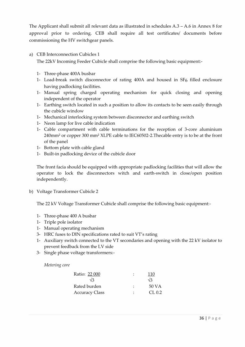
The Applicant shall submit all relevant data as illustrated in schedules A.3 – A.6 in Annex 8 for
approval prior to ordering. CEB shall require all test certificates/ documents before
commissioning the HV switchgear panels.
a) CEB Interconnection Cubicles 1
The 22kV Incoming Feeder Cubicle shall comprise the following basic equipment:-
1- Three-phase 400A busbar
1- Load-break switch disconnector of rating 400A and housed in SF6 filled enclosure
having padlocking facilities.
1- Manual spring charged operating mechanism for quick closing and opening
independent of the operator
1- Earthing switch located in such a position to allow its contacts to be seen easily through
the cubicle window
1- Mechanical interlocking system between disconnector and earthing switch
1- Neon lamp for live cable indication
1- Cable compartment with cable terminations for the reception of 3-core aluminium
240mm² or copper 300 mm² XLPE cable to IEC60502-2.Thecable entry is to be at the front
of the panel
1- Bottom plate with cable gland
1- Built-in padlocking device of the cubicle door
The front facia should be equipped with appropriate padlocking facilities that will allow the
operator to lock the disconnectors witch and earth-switch in close/open position
independently.
b) Voltage Transformer Cubicle 2
The 22 kV Voltage Transformer Cubicle shall comprise the following basic equipment:-
1- Three-phase 400 A busbar
1- Triple pole isolator
1- Manual operating mechanism
3- HRC fuses to DIN specifications rated to suit VT’s rating
1- Auxiliary switch connected to the VT secondaries and opening with the 22 kV isolator to
prevent feedback from the LV side
3- Single phase voltage transformers:-
Metering core
Ratio: 22 000 : 110
√3 √3
Rated burden : 50 VA
Accuracy Class : CL 0.2

37 | P a g e
Protection core
Ratio: 22 000 : 110 or 110 depending on star/delta
√3 √3 3
Rated burden : 30 VA
Accuracy Class : 3P
Burden Range : 0.25 – 1.0 ×Rated burden at 0.8 p.f
Primary voltage range : 0.05 - Vf × rated primary voltage
Rated voltage factor Vf: : 1.9
Time rating (for Vf) : 30 s
1- LV fuse box containing 3 LV fuses + 3 neutral links
1- Built-in padlocking facility on the cubicle door
c) Circuit breaker Cubicle No.3
The circuit breaker shall be of double isolation and comprise the following basic equipment
1- Three-phase 400 A busbar
2- Triple pole isolator
1- SF6 Gas Circuit Breaker
1- Motor operated spring charging mechanism for quick closing and opening both locally
by push button and remotely.
1- Closing coil voltage to harmonise with auxiliary supply of MSDG installation.
1- Spring charging motor voltage to harmonise with auxiliary supply of MSDG
installation.
1- Tripping coil voltage to harmonise with auxiliary supply of MSDG installation.
1- Trip release device to work in conjunction with the relay mentioned below
2- Current transformers with dual primaries of 50/100 rated amp with secondaries of 5A,
Class 5P10, 15 VA burden for protection and two separate cores of 5A Class 0.2, 15 VA
burden for main and back up metering
1- Voltage test terminal box
1- Mechanical interlocking between earthing switch and triple pole isolator
1- Earthing switch located in a position to allow its contacts or position to be seen easily
preferably through the cubicle window
1- Bottom plate with cable gland
1- Neon lamp for live cable indication
1- Built-in padlocking device for the cubicle door
The front facia shall be equipped with appropriate padlocking facilities that will allow the
operator to lock the disconnector switch and earth switch in close/open position
independently. A key interlocking system shall be provided for the safe operation of the
22kV switchgears.
Note:
The current and voltage transformers have to be removed and sent to CEB Meter Laboratory
for necessary tests before commissioning.
Toroidal CTs WILL NOT BE ACCEPTED for metering purpose

38 | P a g e
d) Degree of Protection
IP 3X.
e) Safety equipment for switching operations
Client should provide the following safety equipment:-
i) 22 kV insulating mat
ii) One pair of 22 kV insulating gloves.
Specification of the equipment shall be approved by the CEB prior to ordering
f) Spares
The client shall provide the following spares for the cubicles that shall be under Central
Electricity Board’s responsibility:-
1 set Voltage Transformer as specified in item (b).
1 set Current Transformer as specified in item (c).
1 set HRC fuses as specified in item (b)
g) Standards
The switchboard shall conform to the following standards or the relevant parts thereof: -
(i) IEC 129 : AC Disconnectors (Isolators) and Earthing
Switches
(ii) IEC 265 : HV Switches
(iii) IEC 62271-200 : HV Metal-Enclosed Switchgear and Control Gear
(iv) IEC 282 : High Voltage Fuses
(v) IEC 420 : HV AC Fuse Switch combination and Fuse Circuit Breaker
combinations

39 | P a g e
SCHEDULE A.3 INCOMING FEEDER PANEL
Item No. Description Units Value
1. Rated Voltage kV
2. Rated Current A
3. Rated short time current, IS kA(rms)
4. Making Capacity kApeak
5. Arc quenching medium e.g .SF6 To specify
6. Is double or single break? To specify
7. Type of operating mechanism(manual
spring charged; manual)
To specify
8. Minimum clearance:
(a) Between phases
(b) Live part to earth
mm
mm
9. Type of design contacts:
(a) Movable contacts
(b) Fixed contacts
To specify
10. Type of metal used for contacts:
(a) Movable contacts (b) Fixed contacts
To specify
11. Padlocking facility to allow locking of
disconnector and earth switch in
close/open positions independently
Yes/No
Name of Supplier(s):…………………………………………………………………………
Contact Person:…………………………………………Phone No:………….…..………….
Signature of authorised signatory:………………………………………………………….
Position of authorised signatory:…………….……..………………………………………
Name of authorised signatory:……………….………………………………....................
Date: …………………… Company Seal(Mandatory)

40 | P a g e
SCHEDULE A.4 VOLTAGE TRANSFORMER PANEL
Item No. Description Units Value
1. Rated Voltage kV
2. Rated Current A
3. Type of Disconnector To specify
4. Type of operating mechanism of
Disconnector To specify
5. Standard of HRC fuselinks To specify
6.
Voltage Transformer:-
(a) Number of units installed
(b) Type
(c) Model/Make
(d) Burden
(e) Rated primary voltage
(f) Rated secondary voltage
(g) Accuracy class
(h) Transformation ratio
(i) Rated thermal output
VA
kV
V
VA
7.
Padlocking facility to allow locking of
disconnector and earth switch in
close/open positions independently
Yes/No
Name of Supplier(s):…………………………………………………………………………
Contact Person:……………………………………………Phone No:………….…..………….
Signature of authorised signatory:……………………………………………………………
Position of authorised signatory :…………….……..………………………………………
Name of authorised signatory:……………….………………………………....................
Date: …………………… Company Seal(Mandatory)

41 | P a g e
SCHEDULE A.5 OUTGOING FEEDER/METERING PANEL
Item No. Description Units Value
1. Rated Voltage kV
2. Rated Current A
3. Rated short time current, IS kA(rms)
4. Making Capacity kApeak
5. Arc quenching medium e.g. SF6 To specify
6. Is double or single break? To specify
7. Type of operating
mechanism(manual spring charged;
manual)
To specify
8.
Minimum
clearance:- (a)
Between phases
(b) Live part to earth
mm
mm
9.
Type of design
contacts:- (a) Movable
contacts
(b) Fixed contacts
10.
Type of metal used for
contacts:- (a) Movable contacts
(b) Fixed contacts
To specify
11.
Padlocking facility to allow locking
of disconnector and earth
switch in
close/open positions independently
Yes/No
12.
Current Transformer:-
(a) No. of CT provided
(b) Type (c) Model/Make
(d) Burden for protection
(e) Burden for metering
(f) Accuracy class for protection
(g) Accuracy class for metering
(h) Rated primary current
(i) Rated secondary current
(j) No. of primaries
VA
VA
A
A
Name of Supplier(s):………………………………………………………………………………
Contact Person:………………………………………………Phone No:………….…..………….
Signature of authorised signatory:……………………………………………………………
Position of authorised signatory:…………….……..………………………………………
Name of authorised signatory :……………….………………………………....................
Date: …………………… Company Seal(Mandatory)
42 | P a g e
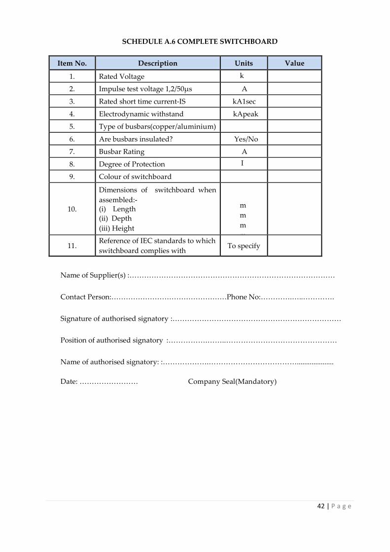
SCHEDULE A.6 COMPLETE SWITCHBOARD
Item No. Description Units Value
1. Rated Voltage k
V
2. Impulse test voltage 1,2/50µs A
3. Rated short time current-IS kA1sec
4. Electrodynamic withstand kApeak
5. Type of busbars(copper/aluminium)
6. Are busbars insulated? Yes/No
7. Busbar Rating A
8. Degree of Protection I
P
9. Colour of switchboard
10.
Dimensions of switchboard when
assembled:- (i) Length
(ii) Depth
(iii) Height
m
m
m
m
m
m
11. Reference of IEC standards to which
switchboard complies with To specify
Name of Supplier(s) :…………………………………………………………………………
Contact Person:…………………………………………Phone No:………….…..………….
Signature of authorised signatory :……………………………………………………………
Position of authorised signatory :…………….……..………………………………………
Name of authorised signatory: :……………….………………………………....................
Date: …………………… Company Seal(Mandatory)

43 | P a g e
Annex 9 - Interconnection Transformer Specifications
(a) Characteristics of the Interconnection Transformer
No. of phases
3
High voltage side
22 kV
Low voltage side
As per MSDG low voltage
Frequency
50 Hz
Type
Oil immersed, hermetically sealed, non-
gas cushion *
Cooling
Natural
Construction
Core type double wound or shell type
Vector Group
Dyn 11
Winding
Enamelled Copper Wire
Standard IEC 60076
* Customers wishing to purchase cast resin transformers (for indoor use), should submit
all detailed characteristics of the proposed units including Type Test Report from an
independent and recognised institution.
(b) Other Requirements
The transformer shall be:-
1. Supplied with oil as per specifications contained in Schedule B.2 – Mineral Insulating
Oil for Transformers and Switchgear.
2. Fitted with:-
(a) Oil level indicator
(b) Oil filling hole with plug
(c) Lifting lugs
(d) Earthing terminal for tank
(e) Drain plug with sampler cock
(f) Diagram and rating plate
(g) Terminal marking plate
(h) Off-circuit tap changer with ± 2 ½% and ± 5% taps (as per the above
mentioned standard)
3. Supplied with detachable top yoke to allow removal of windings for repairs.
4. Externally hot dip galvanised to BS EN ISO 1461.
5. Designed for ground mounting with rollers.
6. Designed with a bolted cover.
7. Designed with the following terminations:-
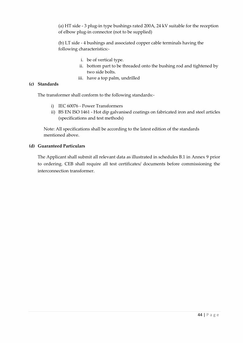
44 | P a g e
(a) HT side - 3 plug-in type bushings rated 200A, 24 kV suitable for the reception
of elbow plug-in connector (not to be supplied)
(b) LT side - 4 bushings and associated copper cable terminals having the
following characteristics:-
i. be of vertical type.
ii. bottom part to be threaded onto the bushing rod and tightened by
two side bolts.
iii. have a top palm, undrilled
(c) Standards
The transformer shall conform to the following standards:-
i) IEC 60076 - Power Transformers
ii) BS EN ISO 1461 - Hot dip galvanised coatings on fabricated iron and steel articles
(specifications and test methods)
Note: All specifications shall be according to the latest edition of the standards
mentioned above.
(d) Guaranteed Particulars
The Applicant shall submit all relevant data as illustrated in schedules B.1 in Annex 9 prior
to ordering. CEB shall require all test certificates/ documents before commissioning the
interconnection transformer.

45 | P a g e
SCHEDULE B.1 INTERCONNECTION TRANSFORMER
Item No. Description Units Value
1. Continuous maximum rating (CMR)
At rated voltage with ONAN cooling
kVA
2. Is transformer totally oil-filled with no gas cushion?
Yes/No
3. Current rating–Amps H.V L.V A
4. Winding connection Vector Group Symbol
5. Impedance Voltage %
6. Normal ratio of transformation at no load
7. Total range of variation of transformation
ratio
±%
8. Size of steps %
9. Tappings on H.V. winding Yes/No
10. Regulation at75°C and at full load as percentage of
normal voltage (a) At unity p.f.
(b) At 0.8p.f.lagging
%
%
11. Fixed losses at normal ratio and 75°C kW
12. Load losses at normal ratio and 75°C
At full rated power
kW
13. Ratio on Inrush Current to Primary Current at 0.3
sec after energising transformer
14. Efficiencyatnormalratioand75°Cat: (a) Rated power at unity powerfactor
(b) Rated power at 0.8 powerfactor
(c) Natural circulation rating
%
%
%
15. Winding temperature:-
Hottest spot temperature at full rated
power(assuming an air temperature at 32°C approx.)
°C

46 | P a g e
Item No. Description Units Value
16. Maximum observable top oil
temperature at:-
(a) Full rated power (assuming an air
temperature at 32°C approx. ) (b) Natural circulation rating
(assuming an air temperature 32°C approx. )
ºC
ºC
17. Calculated ONAN thermal time
constant
Hrs
18. Type of transformer–shell or core
19. Type of core joint-butt or mitred
20. Type of core sheet-cold rolled or hot rolled
21. Maximum current density in
windings:-
H.V.
L.V.
kAsq.m
kAsq.m
22. Whether special surge protection is
provided in conjunction with modified end-
turn reinforcement
Yes/No
23. Type of axial coil supports:-
(a) H.V. winding
(b) L.V. winding
24. Type of radial coil supports:-
(a) H.V. winding (b) L.V. winding
25. Can winding be removed for repairs?
26. Total quantity of oil required to fill
complete transformer
27. Standard specifications of oil used for filling
transformer
28. Is transformer externally hot dip
galvanised?
Yes/No
29. Required for each transformer:- (a) Weight of copper(W)
(b) Weight of cores heets
(c) Weight of all other ferrous parts
kg
kg
kg
30. Approximate weight of core and
winding assembly
kg
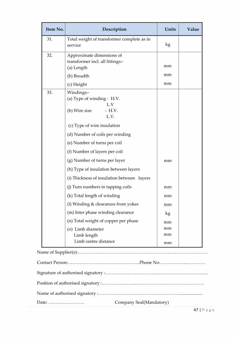
47 | P a g e
Item No. Description Units Value
31. Total weight of transformer complete as in
service
kg
32. Approximate dimensions of
transformer incl. all fittings:-
(a) Length (b) Breadth
(c) Height
mm
mm
mm
33. Windings:-
(a) Type of winding - H.V.
L.V
(b) Wire size - H.V.
L.V.
(c) Type of wire insulation
(d) Number of coils per winding (e) Number of turns per coil
(f) Number of layers per coil
(g) Number of turns per layer
(h) Type of insulation between layers
(i) Thickness of insulation between layers
(j) Turn numbers in tapping coils
(k) Total length of winding (l) Winding & clearances from yokes
(m) Inter phase winding clearance
(n) Total weight of copper per phase
(o) Limb diameter
Limb length
Limb centre distance (p) Top yoke clearance from tank cover
(q) Whether tapping connection are of the
crimped type?
mm
mm
mm
mm
kg
mm
mm
mm
mm
Yes/No
Name of Supplier(s):……………………………………………………………………………
Contact Person:………………………………………….Phone No:………….…..………….
Signature of authorised signatory :……………………………………………………………
Position of authorised signatory :…………….……..………………………………………
Name of authorised signatory :……………….………………………………....................
Date: …………………… Company Seal(Mandatory)
48 | P a g e
Annex 10 - Mineral Insulating Oil For Transformers
The insulating oil shall be for use in transformers and shall comply to IEC 60296 and 60156 or
equivalent.
The oil shall be free of PCB and be of such quality that it shall not require any user
precautionary labelling as defined by the EEC Dangerous Substances Directive 67/548/EEC.
The polycyclic aromatic content by IP 346 shall be maintained below 3%.
GUARANTEED PARTICULARS
The Applicant shall submit all relevant data as illustrated in schedules B.2 in Annex 10 prior to
ordering. CEB shall require all test certificates/ documents before commissioning the
interconnection transformer.

49 | P a g e
SCHEDULE B.2 MINERAL INSULATING OIL FOR TRANSFORMER SWITCHGEAR
Item No. Description Units Value
1. Sludge Value (max.) %
2. Acidity after oxidization (max.) mgKOH/g
3. Flashpoint(closed)–min. ºC
4. Viscosity:- (a) At 15ºC(max.) (b)
At 20ºC (max.)
mm²/s
mm²/s
5. Pour point (max.) ºC
6. Electric strength(breakdown)min. for oil
received in Mauritius in drums
KV/mm
7. Acidity (neutralization value)–max. mgKOH/g
8. Corrosive sulphur
9. Water content (max.)for oil received in
Mauritius in drums
p.p.m.
10. Densityat20ºC(max.0 G/ml
11. Losstangentat90ºC (max.)
12. Resistivity
13. Polycyclic aromatic content(IP346) %
14. Polychlorinated Biphenyls (mg/kg)
15. Reference of standard specifications
16. Are any precautions to be taken incompliance
with the EEC Dangerous Substance Directive 67/548/EEC?
Yes/No
Name of Supplier(s):…………………………………………………………………………
Contact Person:…………………………………………Phone No:………….…..………….
Signature of authorised signatory:……………………………………………………………
Position of authorised signatory :…………….……..………………………………………
Name of authorised signatory:……………….………………………………....................
Date: …………………… Company Seal(Mandatory)
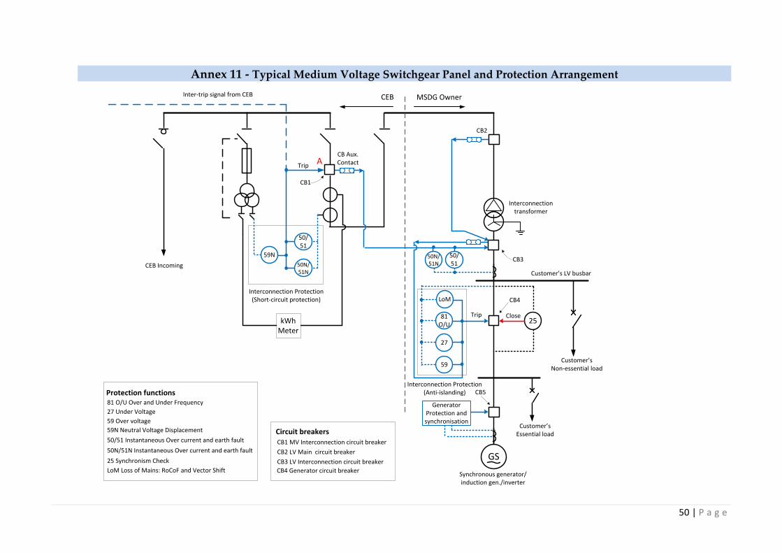
50 | P a g e
Annex 11 - Typical Medium Voltage Switchgear Panel and Protection Arrangement
GS
Interconnection Protection(Short-circuit protection)
CEB Incoming
Synchronous generator/induction gen./inverter
CEB MSDG Owner
Interconnection transformer
50/51
50N/51N
kWhMeter
Inter-trip signal from CEB
Protection functions81 O/U Over and Under Frequency
27 Under Voltage
59 Over voltage
59N Neutral Voltage Displacement
50/51 Instantaneous Over current and earth fault
50N/51N Instantaneous Over current and earth fault
59
27
81 O/U
Trip
Trip
25
Customer’s LV busbar
Customer’s Non-essential load
25 Synchronism Check
Close
Interconnection Protection(Anti-islanding)
GeneratorProtection and synchronisation
LoM
LoM Loss of Mains: RoCoF and Vector Shift
CB Aux. Contact
50/51
50N/51N
CB1
CB3
CB4
CB5
CB1 MV Interconnection circuit breaker
CB2 LV Main circuit breaker
CB3 LV Interconnection circuit breaker
CB4 Generator circuit breaker
Circuit breakers
59N
A
CB2
Customer’s Essential load

51 | P a g e
Annex 12 - Protection Specifications
Interconnection protection
The short circuit protection relay shall have the following characteristics
i. The relay shall comprise an earth fault (EF) protection, at least two over current (OC)
protection and neutral voltage displacement (NVD) protection.
ii. For the EF and OC functions, the relay should comprise the following functions:
- Inverse Definite Minimum Time – Normal Inverse (NI), Very Inverse (VI),
Extremely Inverse (EI)
- Definite Time (DT)
- High Set Instantaneous elements
iii. The setting ranges should be as follows:
a. Start current (overcurrent)
- At definite time: 0.5...... 5 x In and high set 0.5...... 40 x In & ∞
- At Inverse time: 0.5 ….. 2 x In with time multiplier 0.05 …..1
- Operating time at Definite Time: 0.01.....10s
b. Start current (earth fault)
- At Definite time: 0.1 ….. 0.8 x In and high set 0.1 ….. 10 x In & ∞
- At inverse time: 0.05 …..0.8x In with time multiplier 0.05....1
- Operating time at Definite time: 0.01.....10s
iv. The NVD protection function is activated if the residual voltage V0 is greater than a
threshold voltage Vr and incorporates a definite time delay T. The residual voltage is
either obtained by calculation from the three phase voltages or measured using an
external voltage transformer. Note that the voltage transformers used for the purpose
of NVD protection need to be of single phase type connected in star on the primary side
and star or delta on secondary.
a. Threshold voltage, Vr
Range: From 2 % of Unp to 80 % Unp
Precision: ±2 % or ±0.005Unp
Resolution: 1 %
Where, is the line voltage of 22 kV
b. Clearance time Range: 0 s to 300 s Precision: ±2 % or ±25ms Resolution: 10 ms or 1 digit
These shall operate without auxiliary supply, with independent time settings for each type of
protection as detailed hereunder.

52 | P a g e
Annex 13 - Communication Requirement
Figure A - 1 Communication channel setup
MW analog inputs analog outputs
Mvar
kV 4-20mA signals 4-20mA signals
CB positions digital inputs digital outputs
& alarms
potential free contacts
for CB positions and alarms
CB open digital outputs digital inputs
CB closed
commands
customer premises CEB substation
optical fibres
single mode
ST connectors
Transducer
OpticalConverter
OpticalConverter
Existing substation
RTU
power supply
power supply
Pat
ch p
ane
ls
Pat
ch p
ane
ls
53 | P a g e
A. Analog / Digital Fiber Optic Converter
At least 4 uni-directional analog channels for monitoring of MW, MVAr and voltage + 1
spare
At least 10 digital channels for circuit breaker positions/status, alarm monitoring and for
telecontrol of circuit breakers
Sampling method: True simultaneous sampling for all Inputs and Outputs.
The I/O board for connecting external signals to the module should be included.
Analog outputs : 4-20mA
Digital outputs: volt free contacts
B. Optical Fiber
Single mode Fiber with ST connectors. Corresponding patch cords and patch panels
complete with accessories to be included.
C. Power Supply:
48Vdc / 12V dc Volts, 3A low noise, linear, regulated power supply on CEB side

54 | P a g e
Annex 14 - Typical 22 kV Switchgear Room