griggs-walnut ground water plume sitedbsa-client-access.com/gp/_vol i_griggs-walnut...
TRANSCRIPT

GRIGGS-WALNUT GROUND WATER PLUME SITE
PROJECT NO. 11-12-154
VOLUME I OF II CITY COUNCILORS FOR THE BOARD OF COUNTY COMMISSIONERS OF CITY OF LAS CRUCES, NEW MEXICO DOÑA ANA COUNTY, NEW MEXICO MIGUEL SILVA DOLORES SALDAÑA-CAVINESS DOLORES CONNOR KAREN G. PEREZ OLGA PEDROZA SCOTT A. KRAHLING NATHAN SMALL LETICIA DUARTE-BENAVIDEZ GILL SORG BILLY G. GARRETT SHARON THOMAS
CITY OF LAS CRUCES MAYOR, KEN MIYAGISHIMA
FUNDING PROVIDED BY: SAP 07-4453-GF NMFA 1974-DW SAP 07-3228-GF SAP 08-3855-GF
PREPARED BY: DANIEL B. STEPHENS & ASSOCIATES, INC.
GUNDAR PETERSON, P.E.
CITY OF LAS CRUCES 700 NORTH MAIN, ROOM 3134 (3RD FLOOR)
LAS CRUCES, NEW MEXICO 88004

Griggs-Walnut Ground Water Plume Site Las Cruces, New Mexico
Project Manual
Bidding Documents
Invitation to Bid
Instructions to Bidders for Construction Contracts
Bid Form for Construction Contracts
Bid Bond
Contract Documents
Notice of Award
Agreement Between Owner and Contractor for Construction Contract (Stipulated Price)
Notice to Proceed
Performance Bond
Payment Bond
Contractor’s Application for Payment
Certificate of Substantial Completion
Standard General Conditions of the Construction Contract
Change Order
Field Order
Supplementary Conditions
US EPA Region 6 Supplemental Conditions for Federally Assisted Water/Wastewater Infrastructures under the FY 2006 Federal Appropriations Act (P.L. 109-54) as Amended
Wage Rate Information
List of Subcontractors Form
New Mexico Finance Authority Sign Template
Geotechnical Engineering Report
Drawings
Specifications

Bidding Documents

INVITATION TO BID
PROJECT NAME: Griggs-Walnut Ground Water Plume Site
PROJECT NUMBER: 11-12-154
BID DUE DATE/TIME July 14, 2011
COVER OF BID ENVELOPES MUST STATE THE FOLLOWING:
Project Number 11-12-154

2
New Mexico State Labor Enforcement Fund Registration Number of Contractors & Subcontractors:
Except as otherwise provided, a Contractor or Subcontractor that submits a Bid valued at more than sixty thousand dollars ($60,000) for a public works project that is subject to the Public Works Minimum Wage Act must be registered with the New Mexico Department of Labor (NMDOL), Labor And Industrial Division, before Bid opening. All tiers of Subcontractors shall be subject to the requirements of this subsection. Bids will not be accepted on public works projects subject to the Public Works Minimum Wage Act, from a Contractor that does not provide proof of required registration for itself or its Subcontractors.
Contractors and Subcontractors may register with the Department of Labor division on a form provided by the NMDOL and in accordance with Labor Department rules. The NMDOL shall charge an annual registration fee of two hundred dollars ($200). The NMDOL shall issue to the applicant a certificate of registration within fifteen days after receiving from the applicant the completed registration form and the registration fee. Contractors and subcontractors may register at www.dol.state.nm.us. Additional information my be obtained by contacting the NMDOL at (505) 827-6837. This project is wholly or partially funded with United States Environmental Protection Agency (EPA) funds, and therefore must comply with all federal cross cutter requirements. Neither the United States, nor its departments, agencies, nor employees, is or will be party to this invitation for Bids or any resulting contract. This procurement will be subject to regulations contained in 40CFR part 31 including the Davis Bacon Act requirements. All qualified applicants will receive consideration for employment without regard to race, color, religion, sex or national origin. Bidders on this work will be required to comply with the President's Executive Order No. 11246, as amended.

EJCDC C-200 Suggested Instructions to Bidders for Construction Contracts Copyright © 2007 National Society of Professional Engineers for EJCDC. All rights reserved.
INSTRUCTIONS TO BIDDERS FOR
CONSTRUCTION CONTRACTS
Prepared by
ENGINEERS JOINT CONTRACT DOCUMENTS COMMITTEE
and
Issued and Published Jointly by
AMERICAN COUNCIL OF ENGINEERING COMPANIES ______________________
ASSOCIATED GENERAL CONTRACTORS OF AMERICA
______________________
AMERICAN SOCIETY OF CIVIL ENGINEERS _______________________
PROFESSIONAL ENGINEERS IN PRIVATE PRACTICE
A Practice Division of the NATIONAL SOCIETY OF PROFESSIONAL ENGINEERS
Endorsed by
CONSTRUCTION SPECIFICATIONS INSTITUTE

EJCDC C-200 Suggested Instructions to Bidders for Construction Contracts Copyright © 2007 National Society of Professional Engineers for EJCDC. All rights reserved.
Copyright © 2007 National Society of Professional Engineers 1420 King Street, Alexandria, VA 22314-2794
(703) 684-2882 www.nspe.org
American Council of Engineering Companies
1015 15th Street N.W., Washington, DC 20005 (202) 347-7474 www.acec.org
American Society of Civil Engineers
1801 Alexander Bell Drive, Reston, VA 20191-4400 (800) 548-2723 www.asce.org
Associated General Contractors of America
2300 Wilson Boulevard, Suite 400, Arlington, VA 22201-3308 (703) 548-3118 www.agc.org
The copyright for this EJCDC document is owned jointly by the four EJCDC sponsoring organizations and held in trust for their benefit by NSPE.

EJCDC C-200 Suggested Instructions to Bidders for Construction Contracts Copyright © 2007 National Society of Professional Engineers for EJCDC. All rights reserved.
Page iii
INSTRUCTIONS TO BIDDERS
TABLE OF CONTENTS
Page
Article 1 – Defined Terms................................................................................................................................. 1
Article 2 – Copies of Bidding Documents........................................................................................................ 1
Article 3 – Qualifications of Bidders ................................................................................................................ 1
Article 4 – Examination of Bidding Documents, Other Related Data, and Site.............................................. 2
Article 5 – Pre-Bid Conference......................................................................................................................... 4
Article 6 – Site and Other Areas ....................................................................................................................... 5
Article 7 – Interpretations and Addenda........................................................................................................... 6
Article 8 – Bid Security..................................................................................................................................... 6
Article 9 – Contract Times ................................................................................................................................ 6
Article 10 – Liquidated Damages ..................................................................................................................... 6
Article 11 – Substitute and “Or-Equal” Items .................................................................................................. 7
Article 12 – Subcontractors, Suppliers and Others........................................................................................... 7
Article 13 – Preparation of Bid ......................................................................................................................... 8
Article 14 – Basis of Bid; Comparison of Bids ................................................................................................ 9
Article 15 – Submittal of Bid .......................................................................................................................... 10
Article 16 – Modification and Withdrawal of Bid.......................................................................................... 10
Article 17 – Opening of Bids .......................................................................................................................... 10
Article 18 – Bids to Remain Subject to Acceptance....................................................................................... 10
Article 19 – Evaluation of Bids and Award of Contract ................................................................................ 11
Article 20 – Contract Security and Insurance................................................................................................. 12
Article 21 – Signing of Agreement ................................................................................................................. 12
Article 22 – Sales and Use Taxes.................................................................................................................... 12
Article 23 – Retainage ..................................................................................................................................... 12
Article 24 – Contracts to be Assigned ............................................................................................................ 12
Article 25 – Partnering .................................................................................................................................... 12

EJCDC C-200 Suggested Instructions to Bidders for Construction Contracts Copyright © 2007 National Society of Professional Engineers for EJCDC. All rights reserved.
Page 00200 - 1 of 12
ARTICLE 1 – DEFINED TERMS
1.01 Terms used in these Instructions to Bidders have the meanings indicated in the General Conditions and Supplementary Conditions. Additional terms used in these Instructions to Bidders have the meanings indicated below:
A. Issuing Office – The office from which the Bidding Documents are to be issued and where the bidding procedures are to be administered. The Issuing Office for the Work described in these documents is City of Las Cruces Purchasing Department, 700 North Main, Room 3134 (3rd Floor), Las Cruces, New Mexico 88001.
B. Owner - The individual or entity with whom Contractor has entered into the Agreement and for whom the Work is to be performed. The Owner for the Work described in these documents is the City of Las Cruces on behalf of itself and as fiscal agent for the County Doña Ana for the Joint Superfund Project.
ARTICLE 2 – COPIES OF BIDDING DOCUMENTS
2.01 Complete sets of the Bidding Documents in the number and for the deposit sum, if any, stated in the advertisement or invitation to bid may be obtained from the Issuing Office. The deposit will be refunded to each document holder of record who returns a complete set of Bidding Documents in good condition within 30 daystwo weeks after opening of Bids.
2.02 Complete sets of Bidding Documents shall be used in preparing Bids; neither Owner nor Engineer assumes any responsibility for errors or misinterpretations resulting from the use of incomplete sets of Bidding Documents.
2.03 Owner and Engineer, in making copies of Bidding Documents available on the above terms, do so only for the purpose of obtaining Bids for the Work and do not authorize or confer a license for any other use.
ARTICLE 3 – QUALIFICATIONS OF BIDDERS
3.01 To demonstrate Bidder’s qualifications to perform the Work, within ten days of Owner’s request, Bidder shall submit written evidence such as financial data, previous experience, present commitments, and such other data as may be called for below.
A. Bidder shall provide evidence of possession of the required state contractor license, including License Number, Expiration Date, and the Classification applying to the Bid. Otherwise, Bidder shall provide evidence of its ability to obtain possession of the required state contractor license.
B. Bidder shall provide with the Bid a list of Subcontractors. The listing shall include the name and nature of the work for each Subcontractor performing work or labor or rendering service to the Bidder in an amount in excess of ½ of 1 percent of the total Bid amount.
C. Bond Requirements to perform the Work:

EJCDC C-200 Suggested Instructions to Bidders for Construction Contracts Copyright © 2007 National Society of Professional Engineers for EJCDC. All rights reserved.
Page 00200 - 2 of 12
1. Bid Bond
2. Performance Bond
3. Payment Bond
D. Certificates of insurance.
E. It is hereby confirmed that gross receipts taxes are not included in the bid pricing; however, pay requests relating to this project submitted by the successful Bidder shall include New Mexico Gross Receipts Tax at the local prevailing rate per Paragraph 6.10 of the General Conditions.
3.02 Bidder is advised to carefully review those portions of the Bid Form requiring Bidder’s representations and certifications. At the request of the Owner, the Bidder shall provide documentation reflecting the genuineness of the Bid.
ARTICLE 4 – EXAMINATION OF BIDDING DOCUMENTS, OTHER RELATED DATA, AND SITE
4.01 Subsurface and Physical Conditions
A. The Supplementary Conditions identify:
1. Those reports known to Owner of explorations and tests of subsurface conditions at or contiguous to the Site.
2. Those drawings known to Owner of physical conditions relating to existing surface or subsurface structures at the Site (except Underground Facilities).
B. Copies of reports and drawings referenced in Paragraph 4.01.A will be made available by Owner to any Bidder on request. Those reports and drawings are not part of the Contract Documents, but the “technical data” contained therein upon which Bidder is entitled to rely as provided in Paragraph 4.02 of the General Conditions has been identified and established in Paragraph 4.02 of the Supplementary Conditions. Bidder is responsible for any interpretation or conclusion Bidder draws from any “technical data” or any other data, interpretations, opinions, or information contained in such reports or shown or indicated in such drawings.
4.02 Underground Facilities
A. Information and data shown or indicated in the Bidding Documents with respect to existing Underground Facilities at or contiguous to the Site is based upon information and data furnished to Owner and Engineer by owners of such Underground Facilities, including Owner, or others.
4.03 Hazardous Environmental Condition
A. The Supplementary Conditions identify any reports and drawings known to Owner relating to a Hazardous Environmental Condition identified at the Site.

EJCDC C-200 Suggested Instructions to Bidders for Construction Contracts Copyright © 2007 National Society of Professional Engineers for EJCDC. All rights reserved.
Page 00200 - 3 of 12
B. Copies of reports and drawings referenced in Paragraph 4.03.A will be made available by Owner to any Bidder on request. Those reports and drawings are not part of the Contract Documents, but the “technical data” contained therein upon which Bidder is entitled to rely as provided in Paragraph 4.06 of the General Conditions has been identified and established in Paragraph 4.06 of the Supplementary Conditions. Bidder is responsible for any interpretation or conclusion Bidder draws from any “technical data” or any other data, interpretations, opinions, or information contained in such reports or shown or indicated in such drawings.
4.04 Provisions concerning responsibilities for the adequacy of data furnished to prospective Bidders with respect to subsurface conditions, other physical conditions, and Underground Facilities, and possible changes in the Bidding Documents due to differing or unanticipated subsurface or physical conditions appear in Paragraphs 4.02, 4.03, and 4.04 of the General Conditions. Provisions concerning responsibilities for the adequacy of data furnished to prospective Bidders with respect to a Hazardous Environmental Condition at the Site, if any, and possible changes in the Contract Documents due to any Hazardous Environmental Condition uncovered or revealed at the Site which was not shown or indicated in the Drawings or Specifications or identified in the Contract Documents to be within the scope of the Work, appear in Paragraph 4.06 of the General Conditions.
4.05 On request, Owner will provide Bidder access to the Site to conduct such examinations, investigations, explorations, tests, and studies as Bidder deems necessary for submission of a Bid. Bidder shall fill all holes and clean up and restore the Site to its former condition upon completion of such explorations, investigations, tests, and studies. Bidder shall comply with all applicable Laws and Regulations relative to excavation and utility locates.
4.06 A. Reference is made to Article 7 of the Supplementary Conditions for the identification of the general nature of other work that is to be performed at the Site by Owner or others (such as utilities and other prime contractors) that relates to the Work contemplated by these Bidding Documents. On request, Owner will provide to each Bidder for examination access to or copies of contract documents (other than portions thereof related to price) for such other work.
B. Paragraph 6.13.C of the General Conditions indicates that if an Owner safety program exists, it will be noted in the Supplementary Conditions.
4.07 It is the responsibility of each Bidder before submitting a Bid to:
A. examine and carefully study the Bidding Documents, and the other related data identified in the Bidding Documents;
B. visit the Site and become familiar with and satisfy Bidder as to the general, local, and Site conditions that may affect cost, progress, and performance of the Work;
C. become familiar with and satisfy Bidder as to all federal, state, and local Laws and Regulations that may affect cost, progress, and performance of the Work;

EJCDC C-200 Suggested Instructions to Bidders for Construction Contracts Copyright © 2007 National Society of Professional Engineers for EJCDC. All rights reserved.
Page 00200 - 4 of 12
D. carefully study all: (1) reports of explorations and tests of subsurface conditions at or contiguous to the Site and all drawings of physical conditions relating to existing surface or subsurface structures at the Site (except Underground Facilities) that have been identified in Paragraph 4.02 of the Supplementary Conditions as containing reliable "technical data," and (2) reports and drawings of Hazardous Environmental Conditions, if any, at the Site that have been identified in the Paragraph 4.06 of the Supplementary Conditions as containing reliable "technical data";
E. consider the information known to Bidder; information commonly known to contractors doing business in the locality of the Site; information and observations obtained from visits to the Site; the Bidding Documents; and the Site-related reports and drawings identified in the Bidding Documents, with respect to the effect of such information, observations, and documents on (1) the cost, progress, and performance of the Work; (2) the means, methods, techniques, sequences, and procedures of construction to be employed by Bidder, including applying any specific means, methods, techniques, sequences, and procedures of construction expressly required by the Bidding Documents; and (3) Bidder’s safety precautions and programs;
F. agree at the time of submitting its Bid that no further examinations, investigations, explorations, tests, studies, or data are necessary for the determination of its Bid for performance of the Work at the price(s) bid and within the times required, and in accordance with the other terms and conditions of the Bidding Documents;
G. become aware of the general nature of the work to be performed by Owner and others at the Site that relates to the Work as indicated in the Bidding Documents;
H. promptly give Engineer Issuing Office written notice of all conflicts, errors, ambiguities, or discrepancies that Bidder discovers in the Bidding Documents and confirm that the written resolution thereof by Engineer is acceptable to Bidder; and
I. determine that the Bidding Documents are generally sufficient to indicate and convey understanding of all terms and conditions for the performance of the Work.
4.08 The submission of a Bid will constitute an incontrovertible representation by Bidder that Bidder has complied with every requirement of this Article 4, that without exception the Bid is premised upon performing and furnishing the Work required by the Bidding Documents and applying any specific means, methods, techniques, sequences, and procedures of construction that may be shown or indicated or expressly required by the Bidding Documents, that Bidder has given Engineer written notice of all conflicts, errors, ambiguities, and discrepancies that Bidder has discovered in the Bidding Documents and the written resolutions thereof by Engineer are acceptable to Bidder, and that the Bidding Documents are generally sufficient to indicate and convey understanding of all terms and conditions for performing and furnishing the Work.
ARTICLE 5 – PRE-BID CONFERENCE
5.01 A pre-Bid conference will be held at 11:00 a.m. local time on Thursday, June 23, 2011, at City Utilities Office Conference Room 150, 680 N. Motel Blvd., Las Cruces, New Mexico.

EJCDC C-200 Suggested Instructions to Bidders for Construction Contracts Copyright © 2007 National Society of Professional Engineers for EJCDC. All rights reserved.
Page 00200 - 5 of 12
Representatives of Owner and Engineer will be present to discuss the Project. Bidders are required encouraged to attend and participate in the conference. Engineer Issuing Office will transmit to all prospective Bidders of record such Addenda as Engineer considers necessary in response to questions arising at the conference. Oral statements may not be relied upon and will not be binding or legally effective. Issuing Office will record prospective Bidders in attendance and keep a record of the proceedings. Questions or clarifications related to Bid requirements will be addressed at this meeting and in subsequent written Addenda, if applicable.
ARTICLE 6 – SITE AND OTHER AREAS
6.01 The Site is identified in the Bidding Documents. Easements for permanent structures or permanent changes in existing facilities are to be obtained and paid for by Owner unless otherwise provided in the Bidding Documents. All additional lands and access thereto required for temporary construction facilities, construction equipment, or storage of materials and equipment to be incorporated in the Work are to be obtained and paid for by Contractor.

EJCDC C-200 Suggested Instructions to Bidders for Construction Contracts Copyright © 2007 National Society of Professional Engineers for EJCDC. All rights reserved.
Page 00200 - 6 of 12
ARTICLE 7 – INTERPRETATIONS AND ADDENDA
7.01 All questions about the meaning or intent of the Bidding Documents are to be submitted to Engineer Issuing Office in writing. Interpretations or clarifications considered necessary by Engineer in response to such questions will be issued by Addenda mailed or delivered to all parties recorded by Engineer Issuing Office as having received the Bidding Documents. Questions received less than ten days prior to the date for opening of Bids may not be answered. Only questions answered by Addenda will be binding. Oral and other interpretations or clarifications will be without legal effect.
7.02 Addenda may be issued to clarify, correct, or change the Bidding Documents as deemed advisable by Owner or Engineer.
ARTICLE 8 – BID SECURITY
8.01 A Bid must be accompanied by Bid security made payable to Owner in an amount of five percent (5%) of Bidder’s maximum Bid price and in the form of a certified check, bank money order, or a Bid bond (on the form attached) issued by a surety meeting the requirements of Paragraphs 5.01 and 5.02 of the General Conditions.
8.02 The Bid security of the Successful Bidder will be retained until such Bidder has executed the Contract Documents, furnished the required contract security and met the other conditions of the Notice of Award, whereupon the Bid security will be returned. If the Successful Bidder fails to execute and deliver the Contract Documents and furnish the required contract security within 15 days after the Notice of Award, Owner may consider Bidder to be in default, annul the Notice of Award, and the Bid security of that Bidder will be forfeited. Such forfeiture shall be Owner’s exclusive remedy if Bidder defaults. The Bid security of other Bidders whom Owner believes to have a reasonable chance of receiving the award may be retained by Owner until the earlier of seven days after the Effective Date of the Agreement or 61 days after the Bid opening, whereupon Bid security furnished by such Bidders will be returned.
8.03 Bid security of other Bidders whom Owner believes do not have a reasonable chance of receiving the award will be returned within seven daystwo weeks after the Bid opening.
ARTICLE 9 – CONTRACT TIMES
9.01 The number of days within which, or the dates by which, [Milestones are to be achieved and] the Work is to be substantially completed and ready for final payment are set forth in the Agreement.
9.01 The times by which Milestones are to be achieved and for Substantial Completion and readiness for final payment are to be set forth by Bidder in the Bid and will be entered into the Agreement (or incorporated therein by reference to the specific language of the Bid). Substantial Completion is desired within days [on or before ]. The times will be taken into consideration by Owner during the evaluation of Bids, and it will be necessary for the apparent Successful Bidder to satisfy Owner that it will be able to achieve Substantial Completion and be ready for final payment within the times designated in the Bid.
ARTICLE 10 – LIQUIDATED DAMAGES

EJCDC C-200 Suggested Instructions to Bidders for Construction Contracts Copyright © 2007 National Society of Professional Engineers for EJCDC. All rights reserved.
Page 00200 - 7 of 12
10.01 Provisions for liquidated damages, if any, are set forth in the Agreement.
ARTICLE 11 – SUBSTITUTE AND “OR-EQUAL” ITEMS
11.01 The Contract, if awarded, will be on the basis of materials and equipment specified or described in the Bidding Documents without consideration of possible substitute or “or-equal” items. Whenever it is specified or described in the Bidding Documents that a substitute or “or-equal” item of material or equipment may be furnished or used by Contractor if acceptable to Engineer, application for such acceptance will not be considered by Engineer until after the Effective Date of the Agreement.
11.01 The Contract, if awarded, will be on the basis of materials and equipment specified or described in the Bidding Documents, or those substitute or “or-equal” materials and equipment approved by Engineer and identified by Addendum. The materials and equipment described in the Bidding Documents establish a standard of required type, function and quality to be met by any proposed substitute or “or-equal” item. No item of material or equipment will be considered by Engineer as a substitute or “or-equal” unless written request for approval has been submitted by Bidder and has been received by Engineer Issuing Office at least 15 days prior to the date for receipt of Bids. Each such request shall conform to the requirements of Paragraph 6.05 of the General Conditions. The burden of proof of the merit of the proposed item is upon Bidder. Engineer’s decision of approval or disapproval of a proposed item will be final. If Engineer approves any proposed item, such approval will be set forth in an Addendum issued to all prospective Bidders. Bidders shall not rely upon approvals made in any other manner.
ARTICLE 12 – SUBCONTRACTORS, SUPPLIERS AND OTHERS
12.01 If the Supplementary Conditions require the identity of certain Subcontractors, Suppliers, individuals, or entities to be submitted to Owner in advance of a specified date prior to the Effective Date of the Agreement, the apparent Successful Bidder, and any other Bidder so requested, shall within five days after Bid opening, submit to Owner a list of all such Subcontractors, Suppliers, individuals, or entities proposed for those portions of the Work for which such identification is required. Such list shall be accompanied by an experience statement with pertinent information regarding similar projects and other evidence of qualification for each such Subcontractor, Supplier, individual, or entity if requested by Owner. If Owner or Engineer, after due investigation, has reasonable objection to any proposed Subcontractor, Supplier, individual, or entity, Owner may, before the Notice of Award is given, request apparent Successful Bidder to submit a substitute, in which case apparent Successful Bidder shall submit an acceptable substitute, Bidder’s Bid price will be increased (or decreased) by the difference in cost occasioned by such substitution, and Owner may consider such price adjustment in evaluating Bids and making the Contract award.
[without an increase in the Bid.]
12.02 If apparent Successful Bidder declines to make any such substitution, Owner may award the Contract to the next lowest Bidder that proposes to use acceptable Subcontractors, Suppliers, individuals, or entities. Declining to make requested substitutions will not constitute grounds for forfeiture of the Bid security of any Bidder. Any Subcontractor, Supplier, individual, or entity so

EJCDC C-200 Suggested Instructions to Bidders for Construction Contracts Copyright © 2007 National Society of Professional Engineers for EJCDC. All rights reserved.
Page 00200 - 8 of 12
listed and against which Owner or Engineer makes no written objection prior to the giving of the Notice of Award will be deemed acceptable to Owner and Engineer subject to revocation of such acceptance after the Effective Date of the Agreement as provided in Paragraph 6.06 of the General Conditions.
12.03 Contractor shall not be required to employ any Subcontractor, Supplier, individual, or entity against whom Contractor has reasonable objection.
ARTICLE 13 – PREPARATION OF BID
13.01 The Bid Form is included with the Bidding Documents. Additional copies may be obtained from [Engineer or].
13.02 All blanks on the Bid Form shall be completed in ink and the Bid Form signed in ink. Erasures or alterations shall be initialed in ink by the person signing the Bid Form. A Bid price shall be indicated for each section, Bid item, alternative, adjustment unit price item, and unit price item listed therein. In the case of optional alternatives the words “No Bid,” “No Change,” or “Not Applicable” may be entered.
13.03 A Bid by a corporation shall be executed in the corporate name by the president or a vice-president or other corporate officer accompanied by evidence of authority to sign. The corporate seal shall be affixed and attested by the secretary or an assistant secretary. The corporate address and state of incorporation shall be shown.
13.04 A Bid by a partnership shall be executed in the partnership name and signed by a partner (whose title must appear under the signature), accompanied by evidence of authority to sign. The official address of the partnership shall be shown.
13.05 A Bid by a limited liability company shall be executed in the name of the firm by a member and accompanied by evidence of authority to sign. The state of formation of the firm and the official address of the firm shall be shown.
13.06 A Bid by an individual shall show the Bidder’s name and official address.
13.07 A Bid by a joint venture shall be executed by each joint venturer in the manner indicated on the Bid Form. The official address of the joint venture shall be shown.
13.08 All names shall be printed in ink below the signatures.
13.09 The Bid shall contain an acknowledgment of receipt of all Addenda, the numbers of which shall be filled in on the Bid Form.
13.10 Postal and e-mail addresses and telephone number for communications regarding the Bid shall be shown.
13.11 The Bid shall contain evidence of Bidder’s authority and qualification to do business in the state where the Project is located, or Bidder shall covenant in writing to obtain such authority and

EJCDC C-200 Suggested Instructions to Bidders for Construction Contracts Copyright © 2007 National Society of Professional Engineers for EJCDC. All rights reserved.
Page 00200 - 9 of 12
qualification prior to award of the Contract and attach such covenant to the Bid. Bidder’s state contractor license number, if any, shall also be shown on the Bid Form.
ARTICLE 14 – BASIS OF BID; COMPARISON OF BIDS
14.01 Lump Sum
A. Bidders shall submit a Bid on a lump sum basis as set forth in the Bid Form.
A. Bidders shall submit a Bid on a lump sum basis for the base Bid and include a separate price for each alternate described in the Bidding Documents as provided for in the Bid Form. The price for each alternate will be the amount added to or deleted from the base Bid if Owner selects the alternate. In the comparison of Bids, alternates will be applied in the same order as listed in the Bid form.
A. Bidders shall submit a Bid on individual sections or any combination of sections as set forth in the Bid Form.
1. Bidders may submit a Bid for any of the separate sections or any combination of sections as provided in the Bid Form. Submission of a Bid on any section signifies Bidder’s willingness to enter into a Contract for that section alone at the price offered.
1. Bidders offering a Bid on one or more sections shall be capable of completing the Work within the time period stated in the Agreement.
14.02 Unit Price
A. Bidders shall submit a Bid on a unit price basis for each item of Work listed in the Bid schedule.
B. The total of all estimated prices will be the sum of the products of the estimated quantity of each item and the corresponding unit price. The final quantities and Contract Price will be determined in accordance with Paragraph 11.03 of the General Conditions.
C. Discrepancies between the multiplication of units of Work and unit prices will be resolved in favor of the unit prices. Discrepancies between the indicated sum of any column of figures and the correct sum thereof will be resolved in favor of the correct sum.
14.03 Allowances
A. For cash allowances the Bid price shall include such amounts as the Bidder deems proper for Contractor's overhead, costs, profit, and other expenses on account of cash allowances, if any, named in the Contract Documents, in accordance with Paragraph 11.02.B of the General Conditions.
14.04 Completion Time Comparisons

EJCDC C-200 Suggested Instructions to Bidders for Construction Contracts Copyright © 2007 National Society of Professional Engineers for EJCDC. All rights reserved.
Page 00200 - 10 of 12
A. Bid prices will be compared after adjusting for differences in the time designated by Bidders for Substantial Completion. The adjusting amount will be determined at the rate set forth in the Contract Documents for liquidated damages for failing to achieve Substantial Completion for each day before or after the desired date appearing in Article 9 above.
ARTICLE 15 – SUBMITTAL OF BID
15.01 With each copy of the Bidding Documents, a Bidder is furnished one separate unbound copy of the Bid Form, and, if required, the Bid Bond Form. The unbound copy of the Bid Form is to be completed and submitted with the Bid security and the following documents:
A. Required attachments to the Bid as specified in Article 7 of the Bid Form.
15.02 A Bid shall be submitted no later than the date and time prescribed and at the place indicated in the advertisement or invitation to bid and shall be enclosed in a plainly marked package with the Project title (and, if applicable, the designated portion of the Project for which the Bid is submitted), the name and address of Bidder, and shall be accompanied by the Bid security and other required documents. If a Bid is sent by mail or other delivery system, the sealed envelope containing the Bid shall be enclosed in a separate package plainly marked on the outside with the notation “BID ENCLOSED.” A mailed Bid shall be addressed to the Issuing Office.
ARTICLE 16 – MODIFICATION AND WITHDRAWAL OF BID
16.01 A Bid may be modified or withdrawn by an appropriate document duly executed in the same manner that a Bid must be executed and delivered to the place where Bids are to be submitted prior to the date and time for the opening of Bids.
16.02 If within 24 hours after Bids are opened any Bidder files a duly signed written notice with Owner and promptly thereafter demonstrates to the reasonable satisfaction of Owner that there was a material and substantial mistake in the preparation of its Bid, that Bidder may withdraw its Bid, and the Bid security will be returned. Thereafter, if the Work is rebid, that Bidder will be disqualified from further bidding on the Work.
ARTICLE 17 – OPENING OF BIDS
17.01 Bids will be opened at the time and place indicated in the Advertisement or Invitation to Bid and, unless obviously non-responsive, read aloud publicly. An abstract of the amounts of the base Bids and major alternates, if any, will be made available to Bidders after the opening of Bids.
17.01 Bids will be opened privately.
ARTICLE 18 – BIDS TO REMAIN SUBJECT TO ACCEPTANCE
18.01 All Bids will remain subject to acceptance for the period of time stated in the Bid Form, but Owner may, in its sole discretion, release any Bid and return the Bid security prior to the end of this period.

EJCDC C-200 Suggested Instructions to Bidders for Construction Contracts Copyright © 2007 National Society of Professional Engineers for EJCDC. All rights reserved.
Page 00200 - 11 of 12
ARTICLE 19 – EVALUATION OF BIDS AND AWARD OF CONTRACT
19.01 Owner reserves the right to reject any or all Bids, including without limitation, nonconforming, nonresponsive, unbalanced, or conditional Bids. Owner further reserves the right to reject the Bid of any Bidder whom it finds, after reasonable inquiry and evaluation, to not be responsible. Owner may also reject the Bid of any Bidder if Owner believes that it would not be in the best interest of the Project to make an award to that Bidder. Owner also reserves the right to waive all informalities not involving price, time, or changes in the Work and to negotiate contract terms with the Successful Bidder.
19.02 More than one Bid for the same Work from an individual or entity under the same or different names will not be considered. Reasonable grounds for believing that any Bidder has an interest in more than one Bid for the Work may be cause for disqualification of that Bidder and the rejection of all Bids in which that Bidder has an interest.
19.03 In evaluating Bids, Owner will consider whether or not the Bids comply with the prescribed requirements, and such alternates, unit prices and other data, as may be requested in the Bid Form or prior to the Notice of Award.
19.04 In evaluating Bidders, Owner will consider the qualifications of Bidders and may consider the qualifications and experience of Subcontractors, Suppliers, and other individuals or entities proposed for those portions of the Work for which the identity of Subcontractors, Suppliers, and other individuals or entities must be submitted as provided in the Supplementary Conditions.
19.05 Owner may conduct such investigations as Owner deems necessary to establish the responsibility, qualifications, and financial ability of Bidders, proposed Subcontractors, Suppliers, individuals, or entities proposed for those portions of the Work in accordance with the Contract Documents.
19.06 If the Contract is to be awarded, Owner will award the Contract to the Bidder submitting the lowest, responsive, and responsible Bid whose Bid is in the best interests of the Project.

EJCDC C-200 Suggested Instructions to Bidders for Construction Contracts Copyright © 2007 National Society of Professional Engineers for EJCDC. All rights reserved.
Page 00200 - 12 of 12
ARTICLE 20 – CONTRACT SECURITY AND INSURANCE
20.01 Article 5 of the General Conditions, as may be modified by the Supplementary Conditions, sets forth Owner’s requirements as to performance and payment bonds and insurance. When the Successful Bidder delivers the executed Agreement to Owner, it shall be accompanied by such bonds.
ARTICLE 21 – SIGNING OF AGREEMENT
21.01 When Owner issues a Notice of Award to the Successful Bidder, it shall be accompanied by the required number of unsigned counterparts of the Agreement along with the other Contract Documents which are identified in the Agreement as attached thereto. Within 15 days thereafter, Successful Bidder shall sign and deliver the required number of counterparts of the Agreement and attached documents to Owner. Within ten days thereafter, Owner shall deliver one fully signed counterpart to Successful Bidder with a complete set of the Drawings with appropriate identification.
Article 22 – SALES AND USE TAXES
22.01 Owner is exempt from state sales and use taxes on materials and equipment to be incorporated in the Work. (Exemption No. ). Said taxes shall not be included in the Bid. Refer to Paragraph 6.10 of the Supplementary Conditions for additional information.
Article 23 – RETAINAGE
Article 24 – PROVISIONS CONCERNING CONTRACTOR’S RIGHTS TO DEPOSIT SECURITIES IN LIEU OF RETAINAGE ARE SET FORTH IN THE AGREEMENT.CONTRACTS TO BE ASSIGNED
24.01 Owner as “Buyer” [has executed] [will execute] a contract with as “Seller” for the procurement of goods and special services for . The materials and equipment provided for in the procurement contract are to be furnished and delivered to the Site [or other location] for installation by Contractor. The said procurement contract will be assigned by Owner to Contractor as set forth in the Agreement. Contractor will accept the assignment and assume responsibility for the “Seller,” who will become a Supplier to Contractor.
24.02 Bidders may examine the contract documents used by the Owner for the procurement of goods and special services for at .
Article 25 – PARTNERING
25.01 Owner intends to participate in a partnering process with Contractor. The process is intended to help develop better and more effective communication and mutual understanding of common goals. The objectives of the process will be to achieve effective and efficient performance of the Work and completion of the Work within the Contract Price and Contract Times, all in accordance with the Contract Documents.

EJCDC C-200 Suggested Instructions to Bidders for Construction Contracts Copyright © 2007 National Society of Professional Engineers for EJCDC. All rights reserved.
Page 00200 - 13 of 12
25.02 Participation in the partnering process will be voluntary. To initiate the process, within ____days after the Notice to Proceed the key personnel of Owner, Engineer, Contractor, and Contractor’s major Subcontractors will be invited to attend a one-day seminar followed by a one-day team building workshop to develop a partnering statement. The seminar and the workshop will be conducted by a neutral facilitator at a time and location agreed to by Owner and Contractor in the general vicinity of the Site.
25.03 The facilitator will be selected by Owner, subject to approval by Contractor. Costs of the facilitator and facilities for the initial seminar and workshop will be paid by Owner. Thereafter, all facilitator-related and facilities costs will be shared equally by Owner and Contractor with no change in the Contract Price. Each party will pay all costs associated with the participation of its own personnel.
25.04 It is intended that the initial seminar and workshop sessions be followed by periodic half-day evaluation sessions approximately every 90 days as agreed to by Owner and Contractor.
25.05 A primary objective of the partnering process is to maximize the potential for resolution of disputes in a timely and non-adversarial manner. The use of alternative dispute resolution (ADR) methods will be encouraged in order to promote and maintain amicable working relationships among the parties. In the event that ADR procedures are unsuccessful, the dispute resolution provisions set forth in the Contract Documents will be employed.
21.02 These provisions express the intent and spirit of the partnering process, and nothing stated herein or in the partnering statement shall change in any way the rights, responsibilities, and obligations of the parties as set forth in the Contract Documents. The partnering statement will not be a part of the Contract Documents and will not modify any defense, claim, obligation, or right that otherwise exists.

EJCDC C-410 Suggested Bid Form for Construction Contracts Copyright © 2007 National Society of Professional Engineers for EJCDC. All rights reserved.
This document has important legal consequences; consultation with an attorney is encouraged with respect to its use or modification. This document should be adapted to the particular circumstances of the contemplated Project and the controlling Laws and Regulations.
BID FORM FOR CONSTRUCTION CONTRACTS
Prepared by
ENGINEERS JOINT CONTRACT DOCUMENTS COMMITTEE
and
Issued and Published Jointly by
AMERICAN COUNCIL OF ENGINEERING COMPANIES ______________________
ASSOCIATED GENERAL CONTRACTORS OF AMERICA
______________________
AMERICAN SOCIETY OF CIVIL ENGINEERS _______________________
PROFESSIONAL ENGINEERS IN PRIVATE PRACTICE
A Practice Division of the NATIONAL SOCIETY OF PROFESSIONAL ENGINEERS
Endorsed by
CONSTRUCTION SPECIFICATIONS INSTITUTE

EJCDC C-410 Suggested Bid Form for Construction Contracts Copyright © 2007 National Society of Professional Engineers for EJCDC. All rights reserved.
Copyright © 2007 National Society of Professional Engineers 1420 King Street, Alexandria, VA 22314-2794
(703) 684-2882 www.nspe.org
American Council of Engineering Companies
1015 15th Street N.W., Washington, DC 20005 (202) 347-7474 www.acec.org
American Society of Civil Engineers
1801 Alexander Bell Drive, Reston, VA 20191-4400 (800) 548-2723 www.asce.org
Associated General Contractors of America
2300 Wilson Boulevard, Suite 400, Arlington, VA 22201-3308 (703) 548-3118 www.agc.org
The copyright for this EJCDC document is owned jointly by the four EJCDC sponsoring organizations and held in trust for their benefit by NSPE.

EJCDC C-410 Suggested Bid Form for Construction Contracts Copyright © 2007 National Society of Professional Engineers for EJCDC. All rights reserved.
Page iii
BID FORM
PROJECT NAME: Griggs-Walnut Ground Water Plume Site
PROJECT NUMBER: 11-12-154
BID DUE DATE/TIME July 5, 2011
Item No. Description Unit
EstimatedQuantity Bid Unit Price Bid Price
1 Contractor mobilization and demobilization LS 1 $ $ 2 Site work and grading LS 1 $ $ 3 Construction surveying and staking LS 1 $ $ 4 Traffic control and barricading LS 1 $ $
5 Construction permitting, inspections, and SWPPP
LS 1 $ $
6 Site improvements, including drainage pond construction, gravel parking area, fencing, and gates
LS 1 $ $
7 Site demolition LS 1 $ $
8
Submersible pumps SP-1 and SP-2, including wire, drop pipe, check valves, electrical connections, PVC sounding tube, and appurtenances, CIP
LS 1 $ $
9 Well head completion modifications, including fittings, valves, meters, and appurtenances, CIP
EA 2 $ $
10 8-inch-diameter C900 PVC pipe, including fittings, restraints, trenching, backfill, compaction, and asphalt repaving, CIP
LF 1,372 $ $
11 6-inch-diameter C900 PVC pipe including fittings, restraints, trenching, backfill, compaction, and asphalt repaving, CIP
LF 1,372 $ $
12 Yard piping, 4-inch- to 8-inch-diameter, including valves, valve vaults, fittings, restraints, and appurtenances, CIP
LS 1 $ $
13 Influent equalization tank with viton gaskets, including appurtenances
LS 1 $ $
14 Effluent equalization tank, including appurtenances
LS 1 $ $
15 Building and tank foundations, CIP LS 1 $ $
16
Pre-engineered metal building, including interior walls, ceilings, doors, windows, HVAC, plumbing (OSHA-compliant eyewash/shower station, jockey pump, pneumatic tank, etc.), and appurtenances, CIP
LS 1 $ $
17
Process plumbing and piping, including valves, meters and gauges, static mixers, fittings, heat tape, jacketing, insulation, labeling and appurtenances, CIP
LS 1 $ $

EJCDC C-410 Suggested Bid Form for Construction Contracts Copyright © 2007 National Society of Professional Engineers for EJCDC. All rights reserved.
Page iv
Item No. Description Unit
EstimatedQuantity Bid Unit Price Bid Price
18 Influent pump P-1 duplex skid, CIP LS 1 $ $ 19 Effluent pump P-4 duplex skid, CIP LS 1 $ $ 20 Low-profile tray air stripper package EA 2 $ $
21 Chemical feed pumps CFP-1 and CFP-2 and associated appurtenances
EA 2 $ $
22 Sixty day chemical supply (anti-scalant and sodium hypochlorite)
LS 1 $ $
23 Building and wellhouse electrical LS 1 $ $ 24 Instrumentation and Controls, including SCADA LS 1 $ $ Testing: soil and concrete CA 1 $ 1000.00 $ 1000.00
Total of All Bid Prices $ Abbreviations CA Cash allowance CIP Complete in place EA Each LF Linear foot LS Lump sum SWPPP Stormwater pollution prevention plan

EJCDC C-410 Suggested Bid Form for Construction Contracts Copyright © 2007 National Society of Professional Engineers for EJCDC. All rights reserved.
Page v
TABLE OF CONTENTS
Page
Article 1 – Bid Recipient................................................................................................................................... 1
Article 2 – Bidder’s Acknowledgements.......................................................................................................... 1
Article 3 – Bidder’s Representations ................................................................................................................ 1
Article 4 – Bidder’s Certification...................................................................................................................... 2
Article 5 – Basis of Bid ..................................................................................................................................... 3
Article 6 – Time of Completion ........................................................................................................................ 7
Article 7 – Attachments to This Bid ................................................................................................................. 5
Article 8 – Defined Terms................................................................................................................................. 6
Article 9 – Bid Submittal................................................................................................................................... 7

EJCDC C-410 Suggested Bid Form for Construction Contracts Copyright © 2007 National Society of Professional Engineers for EJCDC. All rights reserved.
Page 00410 - 1 of 12
ARTICLE 1 – BID RECIPIENT
1.01 This Bid is submitted to:
City of Las Cruces Purchasing Department 700 North Main, Room 3134 (3rd Floor) Las Cruces, NM 88001
1.02 The undersigned Bidder proposes and agrees, if this Bid is accepted, to enter into an Agreement with Owner in the form included in the Bidding Documents to perform all Work as specified or indicated in the Bidding Documents for the prices and within the times indicated in this Bid and in accordance with the other terms and conditions of the Bidding Documents.
ARTICLE 2 – BIDDER’S ACKNOWLEDGEMENTS
2.01 Bidder accepts all of the terms and conditions of the Instructions to Bidders, including without limitation those dealing with the disposition of Bid security. This Bid will remain subject to acceptance for 60 days after the Bid opening, or for such longer period of time that Bidder may agree to in writing upon request of Owner.
ARTICLE 3 – BIDDER’S REPRESENTATIONS
3.01 In submitting this Bid, Bidder represents that:
A. Bidder has examined and carefully studied the Bidding Documents, other related data identified in the Bidding Documents, and the following Addenda, receipt of which is hereby acknowledged:
Addendum No. Addendum Date
B. Bidder has visited the Site and become familiar with and is satisfied as to the general, local, and
Site conditions that may affect cost, progress, and performance of the Work.
C. Bidder is familiar with and is satisfied as to all Laws and Regulations that may affect cost, progress, and performance of the Work.
D. Bidder has carefully studied all: (1) reports of explorations and tests of subsurface conditions at or contiguous to the Site and all drawings of physical conditions relating to existing surface or subsurface structures at the Site (except Underground Facilities) that have been identified in SC-4.02 as containing reliable "technical data," and (2) reports and drawings of Hazardous Environmental Conditions, if any, at the Site that have been identified in SC-4.06 as containing reliable "technical data."

EJCDC C-410 Suggested Bid Form for Construction Contracts Copyright © 2007 National Society of Professional Engineers for EJCDC. All rights reserved.
Page 00410 - 2 of 12
E. Bidder has considered the information known to Bidder; information commonly known to contractors doing business in the locality of the Site; information and observations obtained from visits to the Site; the Bidding Documents; and the Site-related reports and drawings identified in the Bidding Documents, with respect to the effect of such information, observations, and documents on (1) the cost, progress, and performance of the Work; (2) the means, methods, techniques, sequences, and procedures of construction to be employed by Bidder, including applying the specific means, methods, techniques, sequences, and procedures of construction expressly required by the Bidding Documents; and (3) Bidder’s safety precautions and programs.
F. Based on the information and observations referred to in Paragraph 3.01.E above, Bidder does not consider that further examinations, investigations, explorations, tests, studies, or data are necessary for the determination of this Bid for performance of the Work at the price(s) bid and within the times required, and in accordance with the other terms and conditions of the Bidding Documents.
G. Bidder is aware of the general nature of work to be performed by Owner and others at the Site that relates to the Work as indicated in the Bidding Documents.
H. Bidder has given Engineer Issuing Office written notice of all conflicts, errors, ambiguities, or discrepancies that Bidder has discovered in the Bidding Documents, and the written resolution thereof by Engineer is acceptable to Bidder.
1. The Bidding Documents are generally sufficient to indicate and convey understanding of all terms and conditions for the performance of the Work for which this Bid is submitted.
ARTICLE 4 – BIDDER’S CERTIFICATION
4.01 Bidder certifies that:
A. This Bid is genuine and not made in the interest of or on behalf of any undisclosed individual or entity and is not submitted in conformity with any collusive agreement or rules of any group, association, organization, or corporation;
B. Bidder has not directly or indirectly induced or solicited any other Bidder to submit a false or sham Bid;
C. Bidder has not solicited or induced any individual or entity to refrain from bidding; and
D. Bidder has not engaged in corrupt, fraudulent, collusive, or coercive practices in competing for the Contract. For the purposes of this Paragraph 4.01.D:
1. “corrupt practice” means the offering, giving, receiving, or soliciting of any thing of value likely to influence the action of a public official in the bidding process;
2. “fraudulent practice” means an intentional misrepresentation of facts made (a) to influence the bidding process to the detriment of Owner, (b) to establish bid prices at artificial non-competitive levels, or (c) to deprive Owner of the benefits of free and open competition;

EJCDC C-410 Suggested Bid Form for Construction Contracts Copyright © 2007 National Society of Professional Engineers for EJCDC. All rights reserved.
Page 00410 - 3 of 12
3. “collusive practice” means a scheme or arrangement between two or more Bidders, with or without the knowledge of Owner, a purpose of which is to establish bid prices at artificial, non-competitive levels; and
4. “coercive practice” means harming or threatening to harm, directly or indirectly, persons or their property to influence their participation in the bidding process or affect the execution of the Contract.
E. Bidder has not been debarred, suspended, or otherwise made ineligible for participation in City of Las Cruces, State, or Federal Assistance programs under Executive Order 12549 “Debarment and Suspension” as described in the Federal Register Rules and Regulations. No Contractor or Subcontractor may perform services for this Work if such entity has been suspended or debarred from submitting a Bid for City of Las Cruces, State, or Federal Work during the time such debarment is in effect.
ARTICLE 5 – BASIS OF BID
5.01 Bidder will complete the Work in accordance with the Contract Documents for the following price(s):
FORMAT FOR UNIT PRICE BID
Item No. Description Unit
EstimatedQuantity Bid Unit Price Bid Price
1 Contractor mobilization and demobilization LS 1 $ $ 2 Site work and grading LS 1 $ $ 3 Construction surveying and staking LS 1 $ $ 4 Traffic control and barricading LS 1 $ $
5 Construction permitting, inspections, and SWPPP
LS 1 $ $
6 Site improvements, including drainage pond construction, gravel parking area, fencing, and gates
LS 1 $ $
7 Site demolition LS 1 $ $
8
Submersible pumps SP-1 and SP-2, including wire, drop pipe, check valve, electrical connections, PVC sounding tube, and appurtenances, CIP
LS 1 $ $
9 Well head completion modifications, including fittings, valves, meters, and appurtenances, EA 2 $ $
10 8-inch-diameter C900 PVC pipe including fittings, restraints, trenching, backfill, compaction, and asphalt repaving, CIP
LF 1,372 $ $
11 6-inch-diameter C900 PVC pipe including fittings, restraints, trenching, backfill, compaction, and asphalt repaving, CIP
LF 1,372 $ $

EJCDC C-410 Suggested Bid Form for Construction Contracts Copyright © 2007 National Society of Professional Engineers for EJCDC. All rights reserved.
Page 00410 - 4 of 12
Item No. Description Unit
EstimatedQuantity Bid Unit Price Bid Price
12 Yard piping, 4-inch- to 8-inch-diameter, including valves, valve vaults, fittings, restraints, and appurtenances, CIP
LS 1 $ $
13 Influent equalization tank with viton gaskets, including appurtenances
LS 1 $ $
14 Effluent equalization tank, including appurtenances
LS 1 $ $
15 Building and tank foundations, CIP LS 1 $ $
16
Pre-engineered metal building, including interior walls, ceilings, doors, windows, HVAC, plumbing (OSHA-compliant eyewash/shower station, jockey pump, pneumatic tank, etc.), and appurtenances, CIP
LS 1 $ $
17
Process plumbing and piping, including valves, meters and gauges, static mixers, fittings, heat tape, jacketing, insulation, labeling and appurtenances, CIP
LS 1 $ $
18 Influent pump P-1 duplex skid, CIP LS 1 $ $ 19 Effluent pump P-4 duplex skid, CIP LS 1 $ $ 20 Low-profile tray air stripper package EA 2 $ $
21 Chemical feed pumps CFP-1 and CFP-2 and associated appurtenances
EA 2 $ $
22 Sixty day chemical supply (anti-scalant and sodium hypochlorite)
LS 1 $ $
23 Building and wellhouse electrical LS 1 $ $ 24 Instrumentation and Controls, including SCADA LS 1 $ $ Testing: soil and concrete CA 1 $ $
Total of All Bid Prices $ Abbreviations CA Cash allowance CIP Complete in place EA Each LF Linear foot LS Lump sum SWPPP Stormwater pollution prevention plan
Unit Prices have been computed in accordance with Paragraph 11.03.B of the General Conditions.
Bidder acknowledges that estimated quantities are not guaranteed, and are solely for the purpose of comparison of Bids, and final payment for all unit price Bid items will be based on actual quantities, determined as provided in the Contract Documents.

EJCDC C-410 Suggested Bid Form for Construction Contracts Copyright © 2007 National Society of Professional Engineers for EJCDC. All rights reserved.
Page 00410 - 5 of 12
ARTICLE 6 – TIME OF COMPLETION
6.01 Bidder agrees that the Work will be substantially complete and will be completed and ready for final payment in accordance with Paragraph 14.07 of the General Conditions on or before the dates or within the number of calendar days indicated in the Agreement.
6.01 Bidder agrees that the Work will be substantially complete on or before , and will be completed and ready for final payment in accordance with Paragraph 14.07 of the General Conditions on or before .
6.01 Bidder agrees that the Work will be substantially complete within calendar days after the date when the Contract Times commence to run as provided in Paragraph 2.03 of the General Conditions, and will be completed and ready for final payment in accordance with Paragraph 14.07 of the General Conditions within calendar days after the date when the Contract Times commence to run.
6.02 Bidder accepts the provisions of the Agreement as to liquidated damages.
ARTICLE 7 – ATTACHMENTS TO THIS BID
7.01 The following documents are submitted with and made a condition of this Bid:
A. Required Bid security in the form of EJCDC document number C-430;
B. List of Proposed Subcontractors using the form provided in the Supplementary Conditions modified from City of Las Cruces Standard Bidding Documents;
C. List of Proposed Suppliers;
D. List of Project References;
E. Evidence of authority to do business in the state of the Project; or a written covenant to obtain such license within the time for acceptance of Bids;
F. Contractor’s License No.; Evidence of Bidder’s ability to obtain a State Contractor’s License and a covenant by Bidder to obtain said license within the time for acceptance of Bids;
G. State Labor Enforcement Fund Registration No.;Required Bidder Qualification Statement with Supporting Data; and
H. Required Federal Forms per US EPA Region 6 Supplemental Conditions for Federally Assisted Water/Wastewater Infrastructures under the FY 2006 Federal Appropriations Act (P.L. 109-54) as Amended; and
I. Affidavit of Non-Collusion

EJCDC C-410 Suggested Bid Form for Construction Contracts Copyright © 2007 National Society of Professional Engineers for EJCDC. All rights reserved.
Page 00410 - 6 of 12
ARTICLE 8 – DEFINED TERMS
8.01 The terms used in this Bid with initial capital letters have the meanings stated in the Instructions to Bidders, the General Conditions, and the Supplementary Conditions.

EJCDC C-410 Suggested Bid Form for Construction Contracts Copyright © 2007 National Society of Professional Engineers for EJCDC. All rights reserved.
Page 00410 - 7 of 12
ARTICLE 9 – BID SUBMITTAL
9.01 This Bid is submitted by:
If Bidder is: An Individual Name (typed or printed): By:
(Individual’s signature) Doing business as: A Partnership Partnership Name: By: (Signature of general partner -- attach evidence of authority to sign) Name (typed or printed): A Corporation Corporation Name: (SEAL) State of Incorporation: Type (General Business, Professional, Service, Limited Liability):_______ By: (Signature -- attach evidence of authority to sign) Name (typed or printed): Title: (CORPORATE SEAL) Attest
Date of Qualification to do business in New Mexico is ____/____/____.

EJCDC C-410 Suggested Bid Form for Construction Contracts Copyright © 2007 National Society of Professional Engineers for EJCDC. All rights reserved.
Page 00410 - 8 of 12
A Joint Venture Name of Joint Venture: First Joint Venturer Name: (SEAL) By: (Signature of first joint venture partner -- attach evidence of authority to sign) Name (typed or printed): Title: Second Joint Venturer Name: (SEAL) By: (Signature of second joint venture partner -- attach evidence of authority to sign) Name (typed or printed): Title:
(Each joint venturer must sign. The manner of signing for each individual, partnership, and corporation that is a party to the joint venture should be in the manner indicated above.)
Bidder's Business Address Phone No. _____________________________________ Fax No. E-mail ______________________________ _______ SUBMITTED on , 20____. State Contractor License No. . State Labor Enforcement Fund Registration No. .

PENAL SUM FORM
EJCDC C-430 Bid Bond (Penal Sum Form) Prepared by the Engineers Joint Contract Documents Committee.
Page 00430 - 1 of 2
BID BOND
Any singular reference to Bidder, Surety, Owner or other party shall be considered plural where applicable.
BIDDER (Name and Address): SURETY (Name and Address of Principal Place of Business): OWNER (Name and Address): City of Las Cruces 700 North Main, Room 3134 Las Cruces, NM 88001 BID Bid Due Date: July 14, 2011 Description (Project Name and Include Location): Griggs-Walnut Ground Water Plume Site, Las Cruces, New Mexico BOND Bond Number: Date (Not earlier than Bid due date): Penal sum $ (Words) (Figures) Surety and Bidder, intending to be legally bound hereby, subject to the terms set forth below, do each cause this Bid Bond to be duly executed by an authorized officer, agent, or representative. BIDDER SURETY (Seal) (Seal) Bidder’s Name and Corporate Seal Surety’s Name and Corporate Seal By: By: Signature Signature (Attach Power of Attorney) Print Name Print Name Title Title Attest: Attest: Signature Signature Title Title Note: Above addresses are to be used for giving any required notice. Provide execution by any additional parties, such as joint venturers, if necessary.

PENAL SUM FORM
EJCDC C-430 Bid Bond (Penal Sum Form) Prepared by the Engineers Joint Contract Documents Committee.
Page 00430 - 2 of 2
1. Bidder and Surety, jointly and severally, bind themselves, their heirs, executors, administrators, successors, and assigns to pay to Owner upon default of Bidder the penal sum set forth on the face of this Bond. Payment of the penal sum is the extent of Bidder’s and Surety’s liability. Recovery of such penal sum under the terms of this Bond shall be Owner’s sole and exclusive remedy upon default of Bidder.
2. Default of Bidder shall occur upon the failure of Bidder to deliver within the time required by the Bidding Documents (or any extension thereof agreed to in writing by Owner) the executed Agreement required by the Bidding Documents and any performance and payment bonds required by the Bidding Documents.
3. This obligation shall be null and void if:
3.1 Owner accepts Bidder’s Bid and Bidder delivers within the time required by the Bidding Documents (or any extension thereof agreed to in writing by Owner) the executed Agreement required by the Bidding Documents and any performance and payment bonds required by the Bidding Documents, or
3.2 All Bids are rejected by Owner, or
3.3 Owner fails to issue a Notice of Award to Bidder within the time specified in the Bidding Documents (or any extension thereof agreed to in writing by Bidder and, if applicable, consented to by Surety when required by Paragraph 5 hereof).
4. Payment under this Bond will be due and payable upon default of Bidder and within 30 calendar days after receipt by Bidder and Surety of written notice of default from Owner, which notice will be given with reasonable promptness, identifying this Bond and the Project and including a statement of the amount due.
5. Surety waives notice of any and all defenses based on or arising out of any time extension to issue Notice of Award agreed to in writing by Owner and Bidder, provided that the total time for issuing Notice of Award including extensions shall not in the aggregate exceed 120 days from Bid due date without Surety’s written consent.
6. No suit or action shall be commenced under this Bond prior to 30 calendar days after the notice of default required in Paragraph 4 above is received by Bidder and Surety and in no case later than one year after Bid due date.
7. Any suit or action under this Bond shall be commenced only in a court of competent jurisdiction located in the state in which the Project is located.
8. Notices required hereunder shall be in writing and sent to Bidder and Surety at their respective addresses shown on the face of this Bond. Such notices may be sent by personal delivery, commercial courier, or by United States Registered or Certified Mail, return receipt requested, postage pre-paid, and shall be deemed to be effective upon receipt by the party concerned.
9. Surety shall cause to be attached to this Bond a current and effective Power of Attorney evidencing the authority of the officer, agent, or representative who executed this Bond on behalf of Surety to execute, seal, and deliver such Bond and bind the Surety thereby.
10. This Bond is intended to conform to all applicable statutory requirements. Any applicable requirement of any applicable statute that has been omitted from this Bond shall be deemed to be included herein as if set forth at length. If any provision of this Bond conflicts with any applicable statute, then the provision of said statute shall govern and the remainder of this Bond that is not in conflict therewith shall continue in full force and effect.
11. The term “Bid” as used herein includes a Bid, offer, or proposal as applicable.

Contract Documents

EJCDC C-510 Notice of Award Prepared by the Engineers Joint Contract Documents Committee and endorsed by the Construction Specifications Institute.
Page 00510 - 1 of 1
Notice of Award
Date: __________________ Project:
Owner: Owner's Contract No.:
Contract: Engineer's Project No.:
Bidder:
Bidder's Address:
You are notified that your Bid dated July 14, 2011 for the above Contract has been considered. You are the Successful Bidder and are awarded a Contract for
The Contract Price of your Contract is Dollars ($ ).
copies of the proposed Contract Documents (except Drawings) accompany this Notice of Award.
sets of the Drawings will be delivered separately or otherwise made available to you immediately.
You must comply with the following conditions precedent within 15 days of the date you receive this Notice of Award.
1. Deliver to the Owner fully executed counterparts of the Contract Documents.
2. Deliver with the executed Contract Documents the Contract security [Bonds] as specified in the Instructions to Bidders (Article 20), General Conditions (Paragraph 5.01), and Supplementary Conditions (Paragraph SC-5.01).
3. Other conditions precedent:
Failure to comply with these conditions within the time specified will entitle Owner to consider you in default, annul this Notice of Award, and declare your Bid security forfeited.
Within ten days after you comply with the above conditions, Owner will return to you one fully executed counterpart of the Contract Documents.
Owner By: Authorized Signature Title Copy to Engineer

EJCDC C-521 Suggested Form of Agreement Between Owner and Contractor for Construction Contract (Stipulated Price)
Funding Agency Edition Copyright © 2002 National Society of Professional Engineers for EJCDC. All rights reserved.
This document has important legal consequences; consultation with an attorney is encouraged with respect to its use or modification. This document should be adapted to the particular circumstances of the contemplated Project and the Controlling Law.
FORM OF AGREEMENT BETWEEN OWNER AND CONTRACTOR FOR
CONSTRUCTION CONTRACT (STIPULATED PRICE) FUNDING AGENCY EDITION
Prepared by
ENGINEERS JOINT CONTRACT DOCUMENTS COMMITTEE
and
Issued and Published Jointly By
PROFESSIONAL ENGINEERS IN PRIVATE PRACTICE a practice division of the
NATIONAL SOCIETY OF PROFESSIONAL ENGINEERS ___________________
AMERICAN COUNCIL OF ENGINEERING COMPANIES
___________________
AMERICAN SOCIETY OF CIVIL ENGINEERS
___________________
This document has been approved and endorsed by
The Associated General Contractors of America
and the
Construction Specification Institute
This document has been accepted by United States Department of Agriculture
Rural Utilities Service, Water and Waste Programs

EJCDC C-521 Suggested Form of Agreement Between Owner and Contractor for Construction Contract (Stipulated Price)
Funding Agency Edition Copyright © 2002 National Society of Professional Engineers for EJCDC. All rights reserved.
This Suggested Form of Agreement has been prepared for use with the Standard General Conditions of the Construction Contract, Funding Agency Edition (No. C-710, 2002 Edition). Their provisions are interrelated, and a change in one may necessitate a change in the other. The language contained in the Suggested Instructions to Bidders (No. C-200, 2002 Edition) is also carefully interrelated with the language of this Agreement. Their usage is discussed in the Commentary on EJCDC Construction Documents. See also Guide to the Preparation of Supplementary Conditions (No. C-800, 2002 Edition).
Copyright © 2002 National Society of Professional Engineers 1420 King Street, Alexandria, VA 22314-2794
(703) 684-2882
American Council of Consulting Engineers 1015 15th Street N.W., Washington, DC 20005
(202) 347-7474
American Society of Civil Engineers 1801 Alexander Bell Drive, Reston, VA 20191-4400
(800) 548-2723

EJCDC C-521 Suggested Form of Agreement Between Owner and Contractor for Construction Contract (Stipulated Price)
Funding Agency Edition Copyright © 2002 National Society of Professional Engineers for EJCDC. All rights reserved.
Page 00521 - 1 of 7
FORM OF AGREEMENT BETWEEN OWNER AND CONTRACTOR
FOR CONSTRUCTION CONTRACT (STIPULATED PRICE) FUNDING AGENCY EDITION
THIS AGREEMENT is by and between City of Las Cruces on behalf of itself and as fiscal agent for the
County of Doña Ana for the Joint Superfund Project (“Owner”) and
(“Contractor”).
Owner and Contractor, in consideration of the mutual covenants hereinafter set forth, agree as follows: ARTICLE 1 – WORK
1.01 Contractor shall complete all Work as specified or indicated in the Contract Documents. The Work is generally described as follows:
The Work consists of installation of a water treatment system to remediate tetrachloroethene (PCE) contamination found in ground water using a modified pump and treat strategy. The project involves the construction of a PCE treatment facility and a conveyance system to transport contaminated water from the extraction wells through the treatment facility to the Upper Griggs Reservoir. The treatment facility includes a centralized low-profile tray aeration system housed within a new 3,500-square foot building, influent and effluent equalization tanks, process pumps, HVAC, electrical, instrumentation and controls, plumbing and appurtenances, and associated earthwork. The conveyance system consists of polyvinyl chloride (PVC) C900 raw water lines from wells CLC 18 and CLC 27 to the treatment facility and a PVC C900 treated water line. Refitting the well heads at CLC 18 and 27 with new plumbing, electrical, and instrumentation and controls is also included.
ARTICLE 2 – THE PROJECT
2.01 The Project for which the Work under the Contract Documents may be the whole or only a part is generally described as follows:
Griggs-Walnut Ground Water Plume Site, Las Cruces, New Mexico
ARTICLE 3 – ENGINEER
3.01 The Project has been designed by Daniel B. Stephens & Associates, Inc. (Engineer), who is to act as Owner’s representative, assume all duties and responsibilities, and have the rights and authority assigned to Engineer in the Contract Documents in connection with the completion of the Work in accordance with the Contract Documents.
ARTICLE 4 – CONTRACT TIMES
4.01 Time of the Essence
A. All time limits for Milestones, if any, Substantial Completion, and completion and readiness for final payment as stated in the Contract Documents are of the essence of the Contract.
4.02 Days to Achieve Substantial Completion and Final Payment
A. The Work will be substantially completed within 210 days after the date when the Contract Times commence to run as provided in Paragraph 2.03 of the General Conditions, and completed and ready for final payment in

EJCDC C-521 Suggested Form of Agreement Between Owner and Contractor for Construction Contract (Stipulated Price)
Funding Agency Edition Copyright © 2002 National Society of Professional Engineers for EJCDC. All rights reserved.
Page 00521 - 2 of 7
accordance with Paragraph 14.07 of the General Conditions within 255 days after the date when the Contract Times commence to run.
4.03 Liquidated Damages
A. Contractor and Owner recognize that time is of the essence of this Agreement and that Owner will suffer financial loss if the Work is not completed within the times specified in Paragraph 4.02 above, plus any extensions thereof allowed in accordance with Article 12 of the General Conditions. The parties also recognize the delays, expense, and difficulties involved in proving in a legal or arbitration proceeding the actual loss suffered by Owner if the Work is not completed on time. Accordingly, instead of requiring any such proof, Owner and Contractor agree that as liquidated damages for delay (but not as a penalty), Contractor shall pay Owner $2,500.00 for each day that expires after the time specified in Paragraph 4.02 for Substantial Completion until the Work is substantially complete. After Substantial Completion, if Contractor shall neglect, refuse, or fail to complete the remaining Work within the Contract Time or any proper extension thereof granted by Owner, Contractor shall pay Owner $2,500.00 for each day that expires after the time specified in Paragraph 4.02 for completion and readiness for final payment until the Work is completed and ready for final payment.
ARTICLE 5 – CONTRACT PRICE
5.01 Owner shall pay Contractor for completion of the Work in accordance with the Contract Documents an amount in current funds equal to the sum of the amounts determined pursuant to Paragraphs 5.01.A, 5.01.B, and 5.01.C below:
A. For all Work other than Unit Price Work, a Lump Sum of:
($ ) (words) (figure)
All specific cash allowances are included in the above price and have been computed in accordance with paragraph 11.02 of the General Conditions.
B. For all Unit Price Work, an amount equal to the sum of the established unit price for each separately identified item of Unit Price Work times the estimated quantity of that item as indicated in this paragraph 5.01.B:
As provided in Paragraph 11.03 of the General Conditions, estimated quantities are not guaranteed, and determinations of actual quantities and classifications are to be made by Engineer as provided in Paragraph 9.07 of the General Conditions. Unit prices have been computed as provided in Paragraph 11.03 of the General Conditions.
UNIT PRICE WORK
Item No. Description Unit
Estimated Quantity Unit Price
Total Estimated Price
ESTIMATED TOTAL OF ALL UNIT PRICE WORK $ $( ) (use words) (figure)
C. For all Work, at the prices stated in Contractor’s Bid, attached hereto as an exhibit.

EJCDC C-521 Suggested Form of Agreement Between Owner and Contractor for Construction Contract (Stipulated Price)
Funding Agency Edition Copyright © 2002 National Society of Professional Engineers for EJCDC. All rights reserved.
Page 00521 - 3 of 7
ARTICLE 6 – PAYMENT PROCEDURES
6.01 Submittal and Processing of Payments
A. Contractor shall submit Applications for Payment in accordance with Article 14 of the General Conditions. Applications for Payment will be processed by Engineer as provided in the General Conditions.
6.02 Progress Payments; Retainage
A. Owner shall make progress payments on account of the Contract Price on the basis of Contractor’s Applications for Payment on or about the fifteenth day of each month during performance of the Work as provided in Paragraphs 6.02.A.1 and 6.02.A.2 below. All such payments will be measured by the schedule of values established as provided in Paragraph 2.07.A of the General Conditions (and in the case of Unit Price Work based on the number of units completed) or, in the event there is no schedule of values, as provided in the General Requirements:
1. Prior to Substantial Completion, progress payments will be made in an amount equal to the percentage indicated below but, in each case, less the aggregate of payments previously made and less such amounts as Engineer may determine or Owner may withhold, including but not limited to liquidated damages, in accordance with Paragraph 14.02 of the General Conditions:
a. 95 100 percent of Work completed (with the balance being retainage); and
b. 95 100 percent of cost of materials and equipment not incorporated in the Work (with the balance being retainage).
2. Upon Substantial Completion, Owner shall pay an amount sufficient to increase total payments to Contractor to 95 100 percent of the Work completed, less such amounts as Engineer shall determine in accordance with Paragraph 14.02.B.5 of the General Conditions.
6.03 Final Payment
A. Upon receipt of the final Application for Payment accompanied by Engineer’s recommendation of payment in accordance with Paragraph 14.07 of the General Conditions, Owner shall pay Contractor as provided in Paragraph 14.07 of the General Conditions the remainder of the Contract Price as recommended by Engineer as provided in said Paragraph 14.07, less any sum Owner is entitled to set off against Engineer’s recommendation, including but not limited to liquidated damages.
ARTICLE 7 – INTEREST
7.01 All moneys not paid when due as provided in Article 14 of the General Conditions shall bear interest at the maximum current State legal rate.
ARTICLE 8 – CONTRACTOR’S REPRESENTATIONS
8.01 In order to induce Owner to enter into this Agreement Contractor makes the following representations:
A. Contractor has examined and carefully studied the Contract Documents and the other related data identified in the Bidding Documents.
B. Contractor has visited the Site and become familiar with and is satisfied as to the general, local, and Site conditions that may affect cost, progress, and performance of the Work.
C. Contractor is familiar with and is satisfied as to all federal, state, and local Laws and Regulations that may affect cost, progress, and performance of the Work.

EJCDC C-521 Suggested Form of Agreement Between Owner and Contractor for Construction Contract (Stipulated Price)
Funding Agency Edition Copyright © 2002 National Society of Professional Engineers for EJCDC. All rights reserved.
Page 00521 - 4 of 7
D. Contractor has carefully studied all: (1) reports of explorations and tests of subsurface conditions at or contiguous to the Site and all drawings of physical conditions in or relating to existing surface or subsurface structures at or contiguous to the Site (except Underground Facilities) which have been identified in the Supplementary Conditions as provided in Paragraph 4.02 of the General Conditions and (2) reports and drawings of a Hazardous Environmental Condition, if any, at the Site which has been identified in the Supplementary Conditions as provided in Paragraph 4.06 of the General Conditions.
E. Contractor has obtained and carefully studied (or assumes responsibility for doing so) all additional or supplementary examinations, investigations, explorations, tests, studies, and data concerning conditions (surface, subsurface, and Underground Facilities) at or contiguous to the Site which may affect cost, progress, or performance of the Work or which relate to any aspect of the means, methods, techniques, sequences, and procedures of construction to be employed by Contractor, including any specific means, methods, techniques, sequences, and procedures of construction expressly required by the Bidding Documents, and safety precautions and programs incident thereto.
F. Contractor does not consider that any further examinations, investigations, explorations, tests, studies, or data are necessary for the performance of the Work at the Contract Price, within the Contract Times, and in accordance with the other terms and conditions of the Contract Documents.
G. Contractor is aware of the general nature of work to be performed by Owner and others at the Site that relates to the Work as indicated in the Contract Documents.
H. Contractor has correlated the information known to Contractor, information and observations obtained from visits to the Site, reports and drawings identified in the Contract Documents, and all additional examinations, investigations, explorations, tests, studies, and data with the Contract Documents.
I. Contractor has given Engineer written notice of all conflicts, errors, ambiguities, or discrepancies that Contractor has discovered in the Contract Documents, and the written resolution thereof by Engineer is acceptable to Contractor.
J. The Contract Documents are generally sufficient to indicate and convey understanding of all terms and conditions for performance and furnishing of the Work.
ARTICLE 9 – CONTRACT DOCUMENTS
9.01 Contents
A. The Contract Documents consist of the following:
1. This Agreement (pages 00521-1 to 00521-7, inclusive).
2. Performance bond (pages 00610-1 to 00610-3, inclusive).
3. Payment bond (pages 00615-1 to 00615-3, inclusive).
4. Bid bond (pages 00430-1 to 00430-2, inclusive).
5. General Conditions (pages 00710-1 to 00710-57, inclusive).
6. Supplementary Conditions (pages 00800-1 to 00800-10, inclusive, and U.S. Environmental Protection Agency Region 6 Supplemental conditions for Federally Assisted Water/Wastewater Infrastructures under the FY 2006 Federal Appropriations Act [P.L. 109-54] as Amended, consisting of 23 pages).
7. Specifications as listed in the table of contents of the Project Manual.

EJCDC C-521 Suggested Form of Agreement Between Owner and Contractor for Construction Contract (Stipulated Price)
Funding Agency Edition Copyright © 2002 National Society of Professional Engineers for EJCDC. All rights reserved.
Page 00521 - 5 of 7
8. Drawings consisting of 58 sheets with each sheet bearing the following general title: Griggs-Walnut Ground Water Plume Site, Las Cruces, New Mexico.
9. Addenda (numbers to , inclusive).
10. Exhibits to this Agreement (enumerated as follows):
a. Contractor’s Bid (pages 00410-1 to 00410-12, inclusive).
b. Documentation submitted by Contractor prior to Notice of Award (pages to , inclusive).
11. The following which may be delivered or issued on or after the Effective Date of the Agreement and are not attached hereto:
a. Notice to Proceed (page 00550-1, inclusive).
b. Work Change Directives.
c. Change Order(s).
B. The documents listed in Paragraph 9.01.A are attached to this Agreement (except as expressly noted otherwise above).
C. There are no Contract Documents other than those listed above in this Article 9.
D. The Contract Documents may only be amended, modified, or supplemented as provided in Paragraph 3.04 of the General Conditions.
ARTICLE 10 – MISCELLANEOUS
10.01 Terms
A. Terms used in this Agreement will have the meanings stated in the General Conditions and the Supplementary Conditions.
10.02 Assignment of Contract
A. No assignment by a party hereto of any rights under or interests in the Contract will be binding on another party hereto without the written consent of the party sought to be bound; and, specifically but without limitation, moneys that may become due and moneys that are due may not be assigned without such consent (except to the extent that the effect of this restriction may be limited by law), and unless specifically stated to the contrary in any written consent to an assignment, no assignment will release or discharge the assignor from any duty or responsibility under the Contract Documents.
10.03 Successors and Assigns
A. Owner and Contractor each binds itself, its partners, successors, assigns, and legal representatives to the other party hereto, its partners, successors, assigns, and legal representatives in respect to all covenants, agreements, and obligations contained in the Contract Documents.
10.04 Severability
A. Any provision or part of the Contract Documents held to be void or unenforceable under any Law or Regulation shall be deemed stricken, and all remaining provisions shall continue to be valid and binding upon Owner and

EJCDC C-521 Suggested Form of Agreement Between Owner and Contractor for Construction Contract (Stipulated Price)
Funding Agency Edition Copyright © 2002 National Society of Professional Engineers for EJCDC. All rights reserved.
Page 00521 - 6 of 7
Contractor, who agree that the Contract Documents shall be reformed to replace such stricken provision or part thereof with a valid and enforceable provision that comes as close as possible to expressing the intention of the stricken provision.

EJCDC C-521 Suggested Form of Agreement Between Owner and Contractor for Construction Contract (Stipulated Price)
Funding Agency Edition Copyright © 2002 National Society of Professional Engineers for EJCDC. All rights reserved.
Page 00521 - 7 of 7
IN WITNESS WHEREOF, Owner and Contractor have signed this Agreement in four copies. One counterpart each has been delivered to Owner, Contractor, Engineer, and Agency. All portions of the Contract Documents have been signed, initialed, or identified by Owner and Contractor or identified by Engineer on their behalf.
Note(s) to User See I-21 and correlate procedures for format and signing between the two documents.
This Agreement is dated August 12, 2011. This Agreement shall not be effective unless and until Agency's designatedrepresentative concurs. OWNER: CONTRACTOR
By: By:
Title: Title:
[CORPORATE SEAL] [CORPORATE SEAL]
Attest: Attest:
Title: Title:
Address for giving notices: Address for giving notices:
Agent for service of process:
(If Contractor is a corporation or a partnership, attach evidence of authority to sign.)
Agency Concurrence: As lender or insurer of funds to defray the costs of this Contract, and without liability for any payments thereunder, the Agencyhereby concurs in the form, content, and execution of this Agreement.
Agency: By:
Date: Title:

EJCDC C-550 Notice to Proceed Prepared by the Engineers Joint Contract Documents Committee and endorsed by the Construction Specifications Institute.
Page 00550 - 1 of 1
Notice to Proceed
Date: _________________ Project:
Owner: Owner's Contract No.:
Contract: Engineer's Project No.:
Contractor:
Contractor's Address:
You are notified that the Contract Times under the above Contract will commence to run on September 2, 2011. On or before that date, you are to start performing your obligations under the Contract Documents. In accordance with Article 4 of the Agreement, the date of Substantial Completion is , and the date of readiness for final payment is [(or) the number of days to achieve Substantial Completion is 210, and the number of days to achieve readiness for final payment is 255. Before you may start any Work at the Site, Paragraph 2.01.B of the General Conditions provides that you and Owner must each deliver to the other (with copies to Engineer and other identified additional insureds and loss payees) certificates of insurance which each is required to purchase and maintain in accordance with the Contract Documents. Also, before you may start any Work at the Site, you must: __________________________________.
Owner
Given by:
Authorized Signature
Title
Date
Copy to Engineer

EJCDC C-610 Performance Bond Prepared by the Engineers Joint Contract Documents Committee.
Page 00610 - 1 of 3
PERFORMANCE BOND
Any singular reference to Contractor, Surety, Owner, or other party shall be considered plural where applicable.
CONTRACTOR (Name and Address): SURETY (Name, and Address of Principal Place of Business): OWNER (Name and Address): City of Las Cruces 700 North Main, Room 3134 Las Cruces, NM 88001 CONTRACT Effective Date of Agreement: August 15, 2011 Amount: Description (Name and Location): Griggs-Walnut Ground Water Plume Site, Las Cruces, New Mexico BOND Bond Number:
Date (Not earlier than Effective Date of Agreement):
Amount: Modifications to this Bond Form: Surety and Contractor, intending to be legally bound hereby, subject to the terms set forth below, do each cause this Performance Bond to be duly executed by an authorized officer, agent, or representative. CONTRACTOR AS PRINCIPAL SURETY (Seal) (Seal) Contractor's Name and Corporate Seal Surety’s Name and Corporate Seal By: By: Signature Signature (Attach Power of Attorney) Print Name Print Name Title Title Attest: Attest: Signature Signature Title Title Note: Provide execution by additional parties, such as joint venturers, if necessary.

EJCDC C-610 Performance Bond Prepared by the Engineers Joint Contract Documents Committee.
Page 00610 - 2 of 3
Contractor and Surety, jointly and severally, bind themselves, their heirs, executors, administrators, successors, and assigns to Owner for the performance of the Contract, which is incorporated herein by reference. 1. If Contractor performs the Contract, Surety and Contractor have no obligation under this Bond, except to participate in conferences as provided in Paragraph 2.1. 2. If there is no Owner Default, Surety’s obligation under this Bond shall arise after:
2.1 Owner has notified Contractor and Surety, at the addresses described in Paragraph 9 below, that Owner is considering declaring a Contractor Default and has requested and attempted to arrange a conference with Contractor and Surety to be held not later than 15 days after receipt of such notice to discuss methods of performing the Contract. If Owner, Contractor, and Surety agree, Contractor shall be allowed a reasonable time to perform the Contract, but such an agreement shall not waive Owner’s right, if any, subsequently to declare a Contractor Default; and
2.2 Owner has declared a Contractor Default and formally terminated Contractor’s right to complete the Contract. Such Contractor Default shall not be declared earlier than 20 days after Contractor and Surety have received notice as provided in Paragraph 2.1; and
2.3 Owner has agreed to pay the Balance of the Contract Price to: 1. Surety in accordance with the terms of the Contract; or 2. Another contractor selected pursuant to Paragraph 3.3 to perform the Contract.
3. When Owner has satisfied the conditions of Paragraph 2, Surety shall promptly, and at Surety’s expense, take one of the following actions:
3.1 Arrange for Contractor, with consent of Owner, to perform and complete the Contract; or 3.2 Undertake to perform and complete the Contract itself, through its agents or through independent
contractors; or 3.3 Obtain bids or negotiated proposals from qualified contractors acceptable to Owner for a contract
for performance and completion of the Contract, arrange for a contract to be prepared for execution by Owner and contractor selected with Owner’s concurrence, to be secured with performance and payment bonds executed by a qualified surety equivalent to the bonds issued on the Contract, and pay to Owner the amount of damages as described in Paragraph 5 in excess of the Balance of the Contract Price incurred by Owner resulting from Contractor Default; or
3.4 Waive its right to perform and complete, arrange for completion, or obtain a new contractor, and with reasonable promptness under the circumstances:
1. After investigation, determine the amount for which it may be liable to Owner and, as soon as practicable after the amount is determined, tender payment therefor to Owner; or
2. Deny liability in whole or in part and notify Owner citing reasons therefor.
4. If Surety does not proceed as provided in Paragraph 3 with reasonable promptness, Surety shall be deemed to be in default on this Bond 15 days after receipt of an additional written notice from Owner to Surety demanding that Surety perform its obligations under this Bond, and Owner shall be entitled to enforce any remedy available to Owner. If Surety proceeds as provided in Paragraph 3.4, and Owner refuses the payment tendered or Surety has denied liability, in whole or in part, without further notice Owner shall be entitled to enforce any remedy available to Owner. 5. After Owner has terminated Contractor’s right to complete the Contract, and if Surety elects to act under Paragraph 3.1, 3.2, or 3.3 above, then the responsibilities of Surety to Owner shall not be greater than those of Contractor under the Contract, and the responsibilities of Owner to Surety shall not be greater than those of Owner under the Contract. To the limit of the amount of this Bond, but subject to commitment by Owner of the Balance of the Contract Price to mitigation of costs and damages on the Contract, Surety is obligated without duplication for:

EJCDC C-610 Performance Bond Prepared by the Engineers Joint Contract Documents Committee.
Page 00610 - 3 of 3
5.1 The responsibilities of Contractor for correction of defective Work and completion of the Contract; 5.2 Additional legal, design professional, and delay costs resulting from Contractor’s Default, and
resulting from the actions of or failure to act of Surety under Paragraph 3; and 5.3 Liquidated damages, or if no liquidated damages are specified in the Contract, actual damages
caused by delayed performance or non-performance of Contractor.
6. Surety shall not be liable to Owner or others for obligations of Contractor that are unrelated to the Contract, and the Balance of the Contract Price shall not be reduced or set off on account of any such unrelated obligations. No right of action shall accrue on this Bond to any person or entity other than Owner or its heirs, executors, administrators, or successors. 7. Surety hereby waives notice of any change, including changes of time, to Contract or to related subcontracts, purchase orders, and other obligations. 8. Any proceeding, legal or equitable, under this Bond may be instituted in any court of competent jurisdiction in the location in which the Work or part of the Work is located, and shall be instituted within two years after Contractor Default or within two years after Contractor ceased working or within two years after Surety refuses or fails to perform its obligations under this Bond, whichever occurs first. If the provisions of this paragraph are void or prohibited by law, the minimum period of limitation available to sureties as a defense in the jurisdiction of the suit shall be applicable. 9. Notice to Surety, Owner, or Contractor shall be mailed or delivered to the address shown on the signature page. 10. When this Bond has been furnished to comply with a statutory requirement in the location where the Contract was to be performed, any provision in this Bond conflicting with said statutory requirement shall be deemed deleted herefrom and provisions conforming to such statutory requirement shall be deemed incorporated herein. The intent is that this Bond shall be construed as a statutory bond and not as a common law bond. 11. Definitions.
11.1 Balance of the Contract Price: The total amount payable by Owner to Contractor under the Contract after all proper adjustments have been made, including allowance to Contractor of any amounts received or to be received by Owner in settlement of insurance or other Claims for damages to which Contractor is entitled, reduced by all valid and proper payments made to or on behalf of Contractor under the Contract.
11.2 Contract: The agreement between Owner and Contractor identified on the signature page, including all Contract Documents and changes thereto.
11.3 Contractor Default: Failure of Contractor, which has neither been remedied nor waived, to perform or otherwise to comply with the terms of the Contract.
11.4 Owner Default: Failure of Owner, which has neither been remedied nor waived, to pay Contractor as required by the Contract or to perform and complete or otherwise comply with the other terms thereof.
FOR INFORMATION ONLY – (Name, Address and Telephone) Surety Agency or Broker: Owner’s Representative (Engineer or other party): Daniel B. Stephens & Associates, Inc. - 6020 Academy Road NE, Albuquerque, NM 87109 - (505) 822-9400

{MW001504;1} EJCDC C-615(A) Payment Bond March 2008 Prepared by the Engineers Joint Contract Documents Committee.
Page 00615 - 1 of 3
PAYMENT BOND
Any singular reference to Contractor, Surety, Owner, or other party shall be considered plural where applicable.
CONTRACTOR (Name and Address): SURETY (Name, and Address of Principal Place of Business):
OWNER (Name and Address): City of Las Cruces
700 North Main, Room 3134 Las Cruces, NM 88001
CONTRACT Effective Date of Agreement: August 15, 2011 Amount: Description (Name and Location): Griggs-Walnut Ground Water Plume Site, Las Cruces, New Mexico BOND Bond Number:
Date (Not earlier than Effective Date of Agreement):
Amount: Modifications to this Bond Form: Surety and Contractor, intending to be legally bound hereby, subject to the terms set forth below, do each cause this Payment Bond to be duly executed by an authorized officer, agent, or representative. CONTRACTOR AS PRINCIPAL SURETY (Seal) (Seal) Contractor's Name and Corporate Seal Surety’s Name and Corporate Seal By: By: Signature Signature (Attach Power of Attorney) Print Name Print Name Title Title Attest: Attest: Signature Signature Title Title Note: Provide execution by additional parties, such as joint venturers, if necessary.

{MW001504;1} EJCDC C-615(A) Payment Bond March 2008 Prepared by the Engineers Joint Contract Documents Committee.
Page 00615 - 2 of 3
1. Contractor and Surety, jointly and severally, bind themselves, their heirs, executors, administrators, successors, and assigns to Owner to pay for labor, materials, and equipment furnished by Claimants for use in the performance of the Contract, which is incorporated herein by reference.
2. With respect to Owner, this obligation shall be null and void if Contractor:
2.1 Promptly makes payment, directly or indirectly, for all sums due Claimants, and
2.2 Defends, indemnifies, and holds harmless Owner from all claims, demands, liens, or suits alleging non-payment by Contractor by any person or entity who furnished labor, materials, or equipment for use in the performance of the Contract, provided Owner has promptly notified Contractor and Surety (at the addresses described in Paragraph 12) of any claims, demands, liens, or suits and tendered defense of such claims, demands, liens, or suits to Contractor and Surety, and provided there is no Owner Default.
3. With respect to Claimants, this obligation shall be null and void if Contractor promptly makes payment, directly or indirectly, for all sums due.
4. Surety shall have no obligation to Claimants under this Bond until:
4.1 Claimants who are employed by or have a direct contract with Contractor have given notice to Surety (at the address described in Paragraph 12) and sent a copy, or notice thereof, to Owner, stating that a claim is being made under this Bond and, with substantial accuracy, the amount of the claim.
4.2 Claimants who do not have a direct contract with Contractor:
1. Have furnished written notice to Contractor and sent a copy, or notice thereof, to Owner, within 90 days after having last performed labor or last furnished materials or equipment included in the claim stating, with substantial accuracy, the amount of the claim and the name of the party to whom the materials or equipment were furnished or supplied, or for whom the labor was done or performed; and
2. Have either received a rejection in whole or in part from Contractor, or not received within 30 days of furnishing the above notice any communication from Contractor by which Contractor had indicated the claim will be paid directly or indirectly; and
3. Not having been paid within the above 30 days, have sent a written notice to Surety (at the address described in Paragraph 12) and sent a copy, or notice thereof, to Owner, stating that a claim is being made under this Bond and enclosing a copy of the previous written notice furnished to Contractor.
5. If a notice by a Claimant required by Paragraph 4 is provided by Owner to Contractor or to Surety, that is sufficient compliance.
6. Reserved.
7. Surety’s total obligation shall not exceed the amount of this Bond, and the amount of this Bond shall be credited for any payments made in good faith by Surety.
8. Amounts owed by Owner to Contractor under the Contract shall be used for the performance of the Contract and to satisfy claims, if any, under any performance bond. By Contractor furnishing and Owner accepting this Bond, they agree that all funds earned by Contractor in the performance of the Contract are dedicated to satisfy obligations of Contractor and Surety under this Bond, subject to Owner’s priority to use the funds for the completion of the Work.
9. Surety shall not be liable to Owner, Claimants, or others for obligations of Contractor that are unrelated to the Contract. Owner shall not be liable for payment of any costs or expenses of any Claimant under this Bond, and shall have under this Bond no obligations to make payments to, give notices on behalf of, or

{MW001504;1} EJCDC C-615(A) Payment Bond March 2008 Prepared by the Engineers Joint Contract Documents Committee.
Page 00615 - 3 of 3
otherwise have obligations to Claimants under this Bond.
10. Surety hereby waives notice of any change, including changes of time, to the Contract or to related subcontracts, purchase orders, and other obligations.
11. No suit or action shall be commenced by a Claimant under this Bond other than in a court of competent jurisdiction in the location in which the Work or part of the Work is located or after the expiration of one year from the date (1) on which the Claimant gave the notice required by Paragraph 4.1 or Paragraph 4.2.3, or (2) on which the last labor or service was performed by anyone or the last materials or equipment were furnished by anyone under the Contract, whichever of (1) or (2) first occurs. If the provisions of this paragraph are void or prohibited by law, the minimum period of limitation available to sureties as a defense in the jurisdiction of the suit shall be applicable.
12. Notice to Surety, Owner, or Contractor shall be mailed or delivered to the addresses shown on the signature page. Actual receipt of notice by Surety, Owner, or Contractor, however accomplished, shall be sufficient compliance as of the date received at the address shown on the signature page.
13. When this Bond has been furnished to comply with a statutory requirement in the location where the Contract was to be performed, any provision in this Bond conflicting with said statutory requirement shall be deemed deleted herefrom and provisions conforming to such statutory requirement shall be deemed incorporated herein. The intent is that this Bond shall be construed as a statutory Bond and not as a common law bond.
14. Upon request of any person or entity appearing to be a potential beneficiary of this Bond, Contractor shall promptly furnish a copy of this Bond or shall permit a copy to be made.
15. Definitions
15.1 Claimant: An individual or entity having a direct contract with Contractor, or with a first-tier subcontractor of Contractor, to furnish labor, materials, or equipment for use in the performance of the Contract. The intent of this Bond shall be to include without limitation in the terms “labor, materials or equipment” that part of water, gas, power, light, heat, oil, gasoline, telephone service, or rental equipment used in the Contract, architectural and engineering services required for performance of the Work of Contractor and Contractor’s subcontractors, and all other items for which a mechanic’s lien may be asserted in the jurisdiction where the labor, materials, or equipment were furnished.
15.2 Contract: The agreement between Owner and Contractor identified on the signature page, including all Contract Documents and changes thereto.
15.3 Owner Default: Failure of Owner, which has neither been remedied nor waived, to pay Contractor as required by the Contract, or to perform and complete or otherwise comply with the other terms thereof.
FOR INFORMATION ONLY – (Name, Address, and Telephone) Surety Agency or Broker: Owner’s Representative (Engineer or other): Daniel B. Stephens & Associates, Inc. - 6020 Academy Road NE, Albuquerque, NM 87109 - (505) 822-9400

Contractor's Application for Payment No.Application Period: Application Date:
To (Owner): From (Contractor): Via (Engineer):
Project: Contract:
Owner's Contract No.: Contractor's Project No.: Engineer's Project No.:
1. ORIGINAL CONTRACT PRICE............................................................ $
2. Net change by Change Orders................................................................... $
3. Current Contract Price (Line 1 ± 2).......................................................... $
4. TOTAL COMPLETED AND STORED TO DATE
(Column F on Progress Estimate)............................................................. $
5. RETAINAGE:
a. 0% X Work Completed.......... $
b. 0% X Stored Material............ $
c. Total Retainage (Line 5a + Line 5b)................................ $
6. AMOUNT ELIGIBLE TO DATE (Line 4 - Line 5c).............................. $
7. LESS PREVIOUS PAYMENTS (Line 6 from prior Application)......... $
8. AMOUNT DUE THIS APPLICATION................................................... $
9. BALANCE TO FINISH, PLUS RETAINAGE
(Column G on Progress Estimate + Line 5 above).................................... $
Contractor's Certification
Payment of: $
is recommended by:
Payment of: $
is approved by:
By: Date: Approved by:
Approved Change Orders
Additions
NET CHANGE BY
CHANGE ORDERS
TOTALS
Number
Change Order Summary
Deductions
(Line 8 or other - attach explanation of the other amount)
(Date)
(Engineer)
(Owner)
Endorsed by the Construction Specifications Institute.
Application For Payment
Funding Agency (if applicable)
(Line 8 or other - attach explanation of the other amount)
(Date)
(Date)
The undersigned Contractor certifies that to the best of its knowledge: (1) all previous progress paymentsreceived from Owner on account of Work done under the Contract have been applied on account to discharge Contractor's legitimate obligations incurred in connection with Work covered by prior Applications for Payment; (2) title of all Work, materials and equipment incorporated in said Work or otherwise listed in or covered by this Application for Payment will pass to Owner at time of payment freeand clear of all Liens, security interests and encumbrances (except such as are covered by a Bond acceptable to Owner indemnifying Owner against any such Liens, security interest or encumbrances); and (3) all Work covered by this Application for Payment is in accordance with the Contract Documents and is not defective.
EJCDC C-620 Contractor's Application for Payment© 2007 National Society of Professional Engineers for EJCDC. All rights reserved.
Page 1 of 4

Progress Estimate
For (contract): Application Number:
Application Period: Application Date:
Item C D Materials Presently Total Completed Balance to Finish
This Period Stored (not in C or D) and Stored to Date (B - F)
(C + D + E)
F
From Previous Application (C+D)
B Work Completed
Contractor's Application
Totals
% (F) B
A GE
Specification Section No.
DescriptionScheduled Value
EJCDC C-620 Contractor's Application for Payment© 2007 National Society of Professional Engineers for EJCDC. All rights reserved.
Page 2 of 4

Progress Estimate Contractor's Application
For (contract): Application Number:
Application Period: Application Date:
Balance to Finish
(B - F)
E F
Total Completed and Stored to Date
(D + E)
% (F) B
A B C D
Item
Bid Quantity Unit Price Bid ValueEstimated Quantity Installed
ValueMaterials Presently Stored (not in C)Bid Item No. Description
Totals
EJCDC C-620 Contractor's Application for Payment© 2007 National Society of Professional Engineers for EJCDC. All rights reserved.
Page 3 of 4

Stored Material Summary Contractor's Application
For (contract): Application Number:
Application Period: Application Date:
A B GMaterials Remaining
in Storage ($)(D + E - F)
C D E FStored Previously Stored this Month Incorporated in Work
Date (Month/Year)
Amount ($)
Amount ($)
SubtotalInvoice No.
Shop Drawing Transmittal No.
Materials Description Date (Month/Year)
Amount ($)
Totals
EJCDC C-620 Contractor's Application for Payment© 2007 National Society of Professional Engineers for EJCDC. All rights reserved.
Page 4 of 4

EJCDC C-625 Certificate of Substantial Completion Prepared by the Engineers Joint Contract Documents Committee and endorsed by the Construction Specifications Institute.
Page 00625 - 1 of 2
Certificate of Substantial Completion
Project: Griggs-Walnut Ground Water Plume Site
Owner: City of Las Cruces Owner's Contract No.:
Contract: Engineer's Project No.: ES09.0306
This [tentative] [definitive] Certificate of Substantial Completion applies to:
� All Work under the Contract Documents: �The following specified portions of the Work:
Date of Substantial Completion
The Work to which this Certificate applies has been inspected by authorized representatives of Owner, Contractor, and Engineer, and found to be substantially complete. The Date of Substantial Completion of the Project or portion thereof designated above is hereby declared and is also the date of commencement of applicable warranties required by the Contract Documents, except as stated below. A [tentative] [definitive] list of items to be completed or corrected is attached hereto. This list may not be all-inclusive, and the failure to include any items on such list does not alter the responsibility of the Contractor to complete all Work in accordance with the Contract Documents. The responsibilities between Owner and Contractor for security, operation, safety, maintenance, heat, utilities, insurance and warranties shall be as provided in the Contract Documents except as amended as follows:
� Amended Responsibilities �Not Amended
Owner's Amended Responsibilities:
Contractor's Amended Responsibilities:

EJCDC C-625 Certificate of Substantial Completion Prepared by the Engineers Joint Contract Documents Committee and endorsed by the Construction Specifications Institute.
Page 00625 - 2 of 2
The following documents are attached to and made part of this Certificate:
This Certificate does not constitute an acceptance of Work not in accordance with the Contract Documents nor is it a release of Contractor's obligation to complete the Work in accordance with the Contract Documents.
Executed by Engineer Date
Accepted by Contractor Date
Accepted by Owner Date

EJCDC C-710 Standard General Conditions of the Construction Contract, Funding Agency Edition
Copyright © 2002 National Society of Professional Engineers for EJCDC. All rights reserved. 00710 - 1
This document has important legal consequences; consultation with an attorney is encouraged with respect to its use or modification. This document should be adapted to the particular circumstances of the contemplated Project and the Controlling Law.
STANDARD GENERAL CONDITIONS OF THE CONSTRUCTION CONTRACT
FUNDING AGENCY EDITION
Prepared by
ENGINEERS JOINT CONTRACT DOCUMENTS COMMITTEE
and
Issued and Published Jointly By
PROFESSIONAL ENGINEERS IN PRIVATE PRACTICE a practice division of the
NATIONAL SOCIETY OF PROFESSIONAL ENGINEERS ___________________
AMERICAN COUNCIL OF ENGINEERING COMPANIES
___________________
AMERICAN SOCIETY OF CIVIL ENGINEERS
___________________
This document has been approved and endorsed by
The Associated General Contractors of America
and the
Construction Specification Institute

EJCDC C-710 Standard General Conditions of the Construction Contract, Funding Agency Edition
Copyright © 2002 National Society of Professional Engineers for EJCDC. All rights reserved. 00710 - 2
These General Conditions have been prepared for use with the Suggested Forms of Agreement Between Owner and Contractor Funding Agency Edition No. C-521 (2002 Edition). Their provisions are interrelated and a change in one may necessitate a change in the other. Comments concerning their usage are contained in the EJCDC Construction Documents, General and Instructions (No. C-001, 2002 Edition). For guidance in the preparation of Supplementary Conditions, see Guide to the Preparation of Supplementary Conditions (No. C-800, 2002 Edition).
Copyright © 2002 National Society of Professional Engineers 1420 King Street, Alexandria, VA 22314-2794
(703) 684-2882
American Council of Engineering Companies 1015 15th Street N.W., Washington, DC 20005
(202) 347-7474
American Society of Civil Engineers 1801 Alexander Bell Drive, Reston, VA 20191-4400
(800) 548-2723

EJCDC C-710 Standard General Conditions of the Construction Contract, Funding Agency Edition
Copyright © 2002 National Society of Professional Engineers for EJCDC. All rights reserved. 00710 - 3
TABLE OF CONTENTS
Page
Article 1 – Definitions and Terminology ........................................................................................................................................... 6 1.01 Defined Terms............................................................................................................................................................ 6 1.02 Terminology............................................................................................................................................................... 9
Article 2 – Preliminary Matters ........................................................................................................................................................ 10 2.01 Delivery of Bonds and Evidence of Insurance........................................................................................................ 10 2.02 Copies of Documents............................................................................................................................................... 10 2.03 Commencement of Contract Times; Notice to Proceed.......................................................................................... 10 2.04 Starting the Work..................................................................................................................................................... 11 2.05 Before Starting Construction ................................................................................................................................... 11 2.06 Preconstruction Conference..................................................................................................................................... 11 2.07 Initial Acceptance of Schedules............................................................................................................................... 11
Article 3 – Contract Documents: Intent, Amending, Reuse ........................................................................................................... 11 3.01 Intent......................................................................................................................................................................... 11 3.02 Reference Standards ................................................................................................................................................ 12 3.03 Reporting and Resolving Discrepancies.................................................................................................................. 12 3.04 Amending and Supplementing Contract Documents.............................................................................................. 13 3.05 Reuse of Documents ................................................................................................................................................ 13 3.06 Electronic Data......................................................................................................................................................... 13
Article 4 – Availability of Lands; Subsurface and Physical Conditions; Hazardous Environmental Conditions; Reference Points........................................................................................................................................................................................................... 13
4.01 Availability of Lands ............................................................................................................................................... 13 4.02 Subsurface and Physical Conditions ....................................................................................................................... 14 4.03 Differing Subsurface or Physical Conditions.......................................................................................................... 14 4.04 Underground Facilities ............................................................................................................................................ 15 4.05 Reference Points ...................................................................................................................................................... 16 4.06 Hazardous Environmental Condition at Site ........................................................................................................... 16
Article 5 – Bonds and Insurance....................................................................................................................................................... 18 5.01 Performance, Payment, and Other Bonds ............................................................................................................... 18 5.02 Licensed Sureties and Insurers ................................................................................................................................ 18 5.03 Certificates of Insurance .......................................................................................................................................... 18 5.04 Contractor’s Liability Insurance .............................................................................................................................. 18 5.05 Owner’s Liability Insurance .................................................................................................................................... 19 5.06 Property Insurance ................................................................................................................................................... 20 5.07 Waiver of Rights ...................................................................................................................................................... 21 5.08 Receipt and Application of Insurance Proceeds...................................................................................................... 21 5.09 Acceptance of Bonds and Insurance; Option to Replace........................................................................................ 22 5.10 Partial Utilization, Acknowledgment of Property Insurer ...................................................................................... 22
Article 6 – Contractor’s Responsibilities.......................................................................................................................................... 22 6.01 Supervision and Superintendence............................................................................................................................ 22 6.02 Labor; Working Hours............................................................................................................................................. 22 6.03 Services, Materials, and Equipment ........................................................................................................................ 22 6.04 Progress Schedule .................................................................................................................................................... 23 6.05 Substitutes and “Or-Equals” .................................................................................................................................... 23 6.06 Concerning Subcontractors, Suppliers, and Others ................................................................................................ 25 6.07 Patent Fees and Royalties ........................................................................................................................................ 26 6.08 Permits...................................................................................................................................................................... 26 6.09 Laws and Regulations.............................................................................................................................................. 26 6.10 Taxes ........................................................................................................................................................................ 27

EJCDC C-710 Standard General Conditions of the Construction Contract, Funding Agency Edition
Copyright © 2002 National Society of Professional Engineers for EJCDC. All rights reserved. 00710 - 4
6.11 Use of Site and Other Areas .................................................................................................................................... 27 6.12 Record Documents................................................................................................................................................... 28 6.13 Safety and Protection ............................................................................................................................................... 28 6.14 Safety Representative............................................................................................................................................... 28 6.15 Hazard Communication Programs .......................................................................................................................... 28 6.16 Emergencies ............................................................................................................................................................. 29 6.17 Shop Drawings and Samples ................................................................................................................................... 29 6.18 Continuing the Work ............................................................................................................................................... 30 6.19 Contractor’s General Warranty and Guarantee....................................................................................................... 30 6.20 Indemnification ........................................................................................................................................................ 31 6.21 Delegation of Professional Design Services ........................................................................................................... 31
Article 7 – Other Work at the Site.................................................................................................................................................... 32 7.01 Related Work at Site ................................................................................................................................................ 32 7.02 Coordination............................................................................................................................................................. 32 7.03 Legal Relationships.................................................................................................................................................. 33
Article 8 – Owner’s Responsibilities................................................................................................................................................ 33 8.01 Communications to Contractor................................................................................................................................ 33 8.02 Replacement of Engineer......................................................................................................................................... 33 8.03 Furnish Data............................................................................................................................................................. 33 8.04 Pay When Due ......................................................................................................................................................... 33 8.05 Lands and Easements; Reports and Tests................................................................................................................ 33 8.06 Insurance .................................................................................................................................................................. 33 8.07 Change Orders ......................................................................................................................................................... 34 8.08 Inspections, Tests, and Approvals ........................................................................................................................... 34 8.09 Limitations on Owner’s Responsibilities ................................................................................................................ 34 8.10 Undisclosed Hazardous Environmental Condition ................................................................................................. 34 8.11 Evidence of Financial Arrangements ...................................................................................................................... 34
Article 9 – Engineer’s Status During Construction.......................................................................................................................... 34 9.01 Owner’s Representative........................................................................................................................................... 34 9.02 Visits to Site ............................................................................................................................................................. 34 9.03 Project Representative ............................................................................................................................................. 35 9.04 Authorized Variations in Work ............................................................................................................................... 35 9.05 Rejecting Defective Work ....................................................................................................................................... 35 9.06 Shop Drawings, Change Orders and Payments ...................................................................................................... 35 9.07 Determinations for Unit Price Work ....................................................................................................................... 35 9.08 Decisions on Requirements of Contract Documents and Acceptability of Work.................................................. 35 9.09 Limitations on Engineer’s Authority and Responsibilities ..................................................................................... 36
Article 10 – Changes in the Work; Claims....................................................................................................................................... 36 10.01 Authorized Changes in the Work ............................................................................................................................ 36 10.02 Unauthorized Changes in the Work ........................................................................................................................ 37 10.03 Execution of Change Orders.................................................................................................................................... 37 10.04 Notification to Surety............................................................................................................................................... 37 10.05 Claims....................................................................................................................................................................... 37
Article 11 – Cost of the Work; Allowances; Unit Price Work ........................................................................................................ 38 11.01 Cost of the Work...................................................................................................................................................... 38 11.02 Allowances............................................................................................................................................................... 40 11.03 Unit Price Work ....................................................................................................................................................... 40
Article 12 – Change of Contract Price; Change of Contract Times ................................................................................................ 41 12.01 Change of Contract Price......................................................................................................................................... 41 12.02 Change of Contract Times ....................................................................................................................................... 42 12.03 Delays....................................................................................................................................................................... 42

EJCDC C-710 Standard General Conditions of the Construction Contract, Funding Agency Edition
Copyright © 2002 National Society of Professional Engineers for EJCDC. All rights reserved. 00710 - 5
Article 13 – Tests and Inspections; Correction, Removal or Acceptance of Defective Work........................................................ 43 13.01 Notice of Defects ..................................................................................................................................................... 43 13.02 Access to Work........................................................................................................................................................ 43 13.03 Tests and Inspections ............................................................................................................................................... 43 13.04 Uncovering Work .................................................................................................................................................... 43 13.05 Owner May Stop the Work...................................................................................................................................... 44 13.06 Correction or Removal of Defective Work ............................................................................................................. 44 13.07 Correction Period ..................................................................................................................................................... 44 13.08 Acceptance of Defective Work ............................................................................................................................... 45 13.09 Owner May Correct Defective Work ...................................................................................................................... 45
Article 14 – Payments to Contractor and Completion ..................................................................................................................... 46 14.01 Schedule of Values .................................................................................................................................................. 46 14.02 Progress Payments ................................................................................................................................................... 46 14.03 Contractor’s Warranty of Title ................................................................................................................................ 48 14.04 Substantial Completion............................................................................................................................................ 48 14.05 Partial Utilization ..................................................................................................................................................... 49 14.06 Final Inspection........................................................................................................................................................ 49 14.07 Final Payment .......................................................................................................................................................... 49 14.08 Final Completion Delayed....................................................................................................................................... 50 14.09 Waiver of Claims ..................................................................................................................................................... 51
Article 15 – Suspension of Work and Termination ......................................................................................................................... 51 15.01 Owner May Suspend Work ..................................................................................................................................... 51 15.02 Owner May Terminate for Cause ............................................................................................................................ 51 15.03 Owner May Terminate For Convenience................................................................................................................ 52 15.04 Contractor May Stop Work or Terminate ............................................................................................................... 52
Article 16 – Dispute Resolution ....................................................................................................................................................... 53 16.01 Methods and Procedures.......................................................................................................................................... 53
Article 17 – Miscellaneous ............................................................................................................................................................... 53 17.01 Giving Notice........................................................................................................................................................... 53 17.02 Computation of Times ............................................................................................................................................. 53 17.03 Cumulative Remedies .............................................................................................................................................. 53 17.04 Survival of Obligations............................................................................................................................................ 54 17.05 Controlling Law....................................................................................................................................................... 54 17.06 Headings................................................................................................................................................................... 54
Article 18 – Federal Requirements................................................................................................................................................... 54 18.01 Agency Not a Party.................................................................................................................................................. 54 18.02 Contract Approval.................................................................................................................................................... 54 18.03 Conflict of Interest ................................................................................................................................................... 54 18.04 Gratuities .................................................................................................................................................................. 54 18.05 Audit and Access to Records................................................................................................................................... 55 18.06 Small, Minority and Women’s Businesses.............................................................................................................. 55 18.07 Anti-Kickback.......................................................................................................................................................... 55 18.08 Clean Air and Pollution Control Acts ..................................................................................................................... 55 18.09 State Energy Policy.................................................................................................................................................. 55 18.10 Equal Opportunity Requirements ............................................................................................................................ 55 18.11 Restrictions on Lobbying......................................................................................................................................... 56 18.12 Environmental Requirements .................................................................................................................................. 56

EJCDC C-710 Standard General Conditions of the Construction Contract, Funding Agency Edition
Copyright © 2002 National Society of Professional Engineers for EJCDC. All rights reserved. 00710 - 6
GENERAL CONDITIONS ARTICLE 1 – DEFINITIONS AND TERMINOLOGY
1.01 Defined Terms
A. Wherever used in the Bidding Requirements or Contract Documents and printed with initial capital letters, the terms listed below will have the meanings indicated which are applicable to both the singular and plural thereof. In addition to terms specifically defined, terms with initial capital letters in the Contract Documents include references to identified articles and paragraphs, and the titles of other documents or forms.
1. Addenda – Written or graphic instruments issued prior to the opening of Bids which clarify, correct, or change the Bidding Requirements or the proposed Contract Documents.
2. Agency – The Federal or state agency named as such in the Agreement.
3. Agreement – The written instrument which is evidence of the agreement between Owner and Contractor covering the Work.
4. Application for Payment – The form acceptable to Engineer which is to be used by Contractor during the course of the Work in requesting progress or final payments and which is to be accompanied by such supporting documentation as is required by the Contract Documents.
5. Asbestos – Any material that contains more than one percent asbestos and is friable or is releasing asbestos fibers into the air above current action levels established by the United States Occupational Safety and Health Administration.
6. Bid – The offer or proposal of a Bidder submitted on the prescribed form setting forth the prices for the Work to be performed.
7. Bidder – The individual or entity who submits a Bid directly to Owner.
8. Bidding Documents – The Bidding Requirements and the proposed Contract Documents (including all Addenda).
9. Bidding Requirements – The Advertisement or Invitation to Bid, Instructions to Bidders, bid security of acceptable form, if any, and the Bid Form with any supplements.
10. Change Order – A document recommended by Engineer which is signed by Contractor and Owner and Agency and authorizes an addition, deletion, or revision in the Work or an adjustment in the Contract Price or the Contract Times, issued on or after the Effective Date of the Agreement.
11. Claim – A demand or assertion by Owner or Contractor seeking an adjustment of Contract Price or Contract Times, or both, or other relief with respect to the terms of the Contract. A demand for money or services by a third party is not a Claim.
12. Contract – The entire and integrated written agreement between the Owner and Contractor concerning the Work. The Contract supersedes prior negotiations, representations, or agreements, whether written or oral.
13. Contract Documents – Those items so designated in the Agreement. Only printed or hard copies of the items listed in the Agreement are Contract Documents. Approved Shop Drawings, other Contractor’s submittals, and the reports and drawings of subsurface and physical conditions are not Contract Documents.

EJCDC C-710 Standard General Conditions of the Construction Contract, Funding Agency Edition
Copyright © 2002 National Society of Professional Engineers for EJCDC. All rights reserved. 00710 - 7
14. Contract Price – The moneys payable by Owner to Contractor for completion of the Work in accordance with the Contract Documents as stated in the Agreement (subject to the provisions of Paragraph 11.03 in the case of Unit Price Work).
15. Contract Times – The number of days or the dates stated in the Agreement to: (i) achieve Milestones, if any, (ii) achieve Substantial Completion; and (iii) complete the Work so that it is ready for final payment as evidenced by Engineer’s written recommendation of final payment.
16. Contractor – The individual or entity with whom Owner has entered into the Agreement.
17. Cost of the Work – See Paragraph 11.01.A for definition.
18. Drawings – That part of the Contract Documents prepared or approved by Engineer which graphically shows the scope, extent, and character of the Work to be performed by Contractor. Shop Drawings and other Contractor submittals are not Drawings as so defined.
19. Effective Date of the Agreement – The date indicated in the Agreement on which it becomes effective, but if no such date is indicated, it means the date on which the Agreement is signed and delivered by the last of the two parties to sign and deliver.
20. Engineer – The individual or entity named as such in the Agreement.
21. Field Order – A written order issued by Engineer which requires minor changes in the Work but which does not involve a change in the Contract Price or the Contract Times.
22. General Requirements – Sections of Division 1 of the Specifications. The General Requirements pertain to all sections of the Specifications.
23. Hazardous Environmental Condition – The presence at the Site of Asbestos, PCBs, Petroleum, Hazardous Waste, or Radioactive Material in such quantities or circumstances that may present a substantial danger to persons or property exposed thereto in connection with the Work.
24. Hazardous Waste – The term Hazardous Waste shall have the meaning provided in Section 1004 of the Solid Waste Disposal Act (42 USC Section 6903) as amended from time to time.
25. Laws and Regulations; Laws or Regulations – Any and all applicable laws, rules, regulations, ordinances, codes, and orders of any and all governmental bodies, agencies, authorities, and courts having jurisdiction.
26. Liens – Charges, security interests, or encumbrances upon Project funds, real property, or personal property.
27. Milestone – A principal event specified in the Contract Documents relating to an intermediate completion date or time prior to Substantial Completion of all the Work.
28. Notice of Award – The written notice by Owner to the Successful Bidder stating that upon timely compliance by the Successful Bidder with the conditions precedent listed therein, Owner will sign and deliver the Agreement.
29. Notice to Proceed – A written notice given by Owner to Contractor fixing the date on which the Contract Times will commence to run and on which Contractor shall start to perform the Work under the Contract Documents.
30. Owner – The individual or entity with whom Contractor has entered into the Agreement and for whom the Work is to be performed.
31. PCBs – Polychlorinated biphenyls.

EJCDC C-710 Standard General Conditions of the Construction Contract, Funding Agency Edition
Copyright © 2002 National Society of Professional Engineers for EJCDC. All rights reserved. 00710 - 8
32. Petroleum – Petroleum, including crude oil or any fraction thereof which is liquid at standard conditions of temperature and pressure (60 degrees Fahrenheit and 14.7 pounds per square inch absolute), such as oil, petroleum, fuel oil, oil sludge, oil refuse, gasoline, kerosene, and oil mixed with other non-Hazardous Waste and crude oils.
33. Progress Schedule – A schedule, prepared and maintained by Contractor, describing the sequence and duration of the activities comprising the Contractor’s plan to accomplish the Work within the Contract Times.
34. Project – The total construction of which the Work to be performed under the Contract Documents may be the whole, or a part.
35. Project Manual – The bound documentary information prepared for bidding and constructing the Work. A listing of the contents of the Project Manual, which may be bound in one or more volumes, is contained in the table(s) of contents.
36. Radioactive Material – Source, special nuclear, or byproduct material as defined by the Atomic Energy Act of 1954 (42 USC Section 2011 et seq.) as amended from time to time.
37. Related Entity – An officer, director, partner, employee, agent, consultant, or subcontractor.
38. Resident Project Representative – The authorized representative of Engineer who may be assigned to the Site or any part thereof.
39. Samples – Physical examples of materials, equipment, or workmanship that are representative of some portion of the Work and which establish the standards by which such portion of the Work will be judged.
40. Schedule of Submittals – A schedule, prepared and maintained by Contractor, of required submittals and the time requirements to support scheduled performance of related construction activities.
41. Schedule of Values – A schedule, prepared and maintained by Contractor, allocating portions of the Contract Price to various portions of the Work and used as the basis for reviewing Contractor’s Applications for Payment.
42. Shop Drawings – All drawings, diagrams, illustrations, schedules, and other data or information which are specifically prepared or assembled by or for Contractor and submitted by Contractor to illustrate some portion of the Work.
43. Site – Lands or areas indicated in the Contract Documents as being furnished by Owner upon which the Work is to be performed, including rights-of-way and easements for access thereto, and such other lands furnished by Owner which are designated for the use of Contractor.
44. Specifications – That part of the Contract Documents consisting of written requirements for materials, equipment, systems, standards and workmanship as applied to the Work, and certain administrative requirements and procedural matters applicable thereto.
45. Subcontractor – An individual or entity having a direct contract with Contractor or with any other Subcontractor for the performance of a part of the Work at the Site.
46. Substantial Completion – The time at which the Work (or a specified part thereof) has progressed to the point where, in the opinion of Engineer, the Work (or a specified part thereof) is sufficiently complete, in accordance with the Contract Documents, so that the Work (or a specified part thereof) can be utilized for the purposes for which it is intended. The terms “substantially complete” and “substantially completed” as applied to all or part of the Work refer to Substantial Completion thereof.
47. Successful Bidder – The Bidder submitting a responsive Bid to whom Owner makes an award.

EJCDC C-710 Standard General Conditions of the Construction Contract, Funding Agency Edition
Copyright © 2002 National Society of Professional Engineers for EJCDC. All rights reserved. 00710 - 9
48. Supplementary Conditions – That part of the Contract Documents which amends or supplements these General Conditions.
49. Supplier – A manufacturer, fabricator, supplier, distributor, materialman, or vendor having a direct contract with Contractor or with any Subcontractor to furnish materials or equipment to be incorporated in the Work by Contractor or any Subcontractor.
50. Underground Facilities – All underground pipelines, conduits, ducts, cables, wires, manholes, vaults, tanks, tunnels, or other such facilities or attachments, and any encasements containing such facilities, including those that convey electricity, gases, steam, liquid petroleum products, telephone or other communications, cable television, water, wastewater, storm water, other liquids or chemicals, or traffic or other control systems.
51. Unit Price Work – Work to be paid for on the basis of unit prices.
52. Work – The entire construction or the various separately identifiable parts thereof required to be provided under the Contract Documents. Work includes and is the result of performing or providing all labor, services, and documentation necessary to produce such construction, and furnishing, installing, and incorporating all materials and equipment into such construction, all as required by the Contract Documents.
53. Work Change Directive – A written statement to Contractor issued on or after the Effective Date of the Agreement and signed by Owner and Agency upon recommendation of the Engineer ordering an addition, deletion, or revision in the Work, or responding to differing or unforeseen subsurface or physical conditions under which the Work is to be performed or to emergencies. A Work Change Directive will not change the Contract Price or the Contract Times but is evidence that the parties expect that the change ordered or documented by a Work Change Directive will be incorporated in a subsequently issued Change Order following negotiations by the parties as to its effect, if any, on the Contract Price or Contract Times.
1.02 Terminology
A. The following words or terms are not defined but, when used in the Bidding Requirements or Contract Documents, have the following meaning.
B. Intent of Certain Terms or Adjectives
1. The Contract Documents include the terms “as allowed,” “as approved,” “as ordered”, “as directed” or terms of like effect or import to authorize an exercise of professional judgment by Engineer. In addition, the adjectives “reasonable,” “suitable,” “acceptable,” “proper,” “satisfactory,” or adjectives of like effect or import are used to describe an action or determination of Engineer as to the Work. It is intended that such exercise of professional judgment, action or determination will be solely to evaluate, in general, the Work for compliance with the requirements of and information in the Contract Documents and conformance with the design concept of the completed Project as a functioning whole as shown or indicated in the Contract Documents (unless there is a specific statement indicating otherwise). The use of any such term or adjective is not intended to and shall not be effective to assign to Engineer any duty or authority to supervise or direct the performance of the Work or any duty or authority to undertake responsibility contrary to the provisions of Paragraph 9.09 or any other provision of the Contract Documents.
C. Day
1. The word “day” means a calendar day of 24 hours measured from midnight to the next midnight.

EJCDC C-710 Standard General Conditions of the Construction Contract, Funding Agency Edition
Copyright © 2002 National Society of Professional Engineers for EJCDC. All rights reserved. 00710 - 10
D. Defective
1. The word “defective,” when modifying the word “Work,” refers to Work that is unsatisfactory, faulty, or deficient in that it:
a. does not conform to the Contract Documents, or
b. does not meet the requirements of any applicable inspection, reference standard, test, or approval referred to in the Contract Documents, or
c. has been damaged prior to Engineer’s recommendation of final payment (unless responsibility for the protection thereof has been assumed by Owner at Substantial Completion in accordance with Paragraph 14.04 or 14.05).
E. Furnish, Install, Perform, Provide
1. The word “furnish,” when used in connection with services, materials, or equipment, shall mean to supply and deliver said services, materials, or equipment to the Site (or some other specified location) ready for use or installation and in usable or operable condition.
2. The word “install,” when used in connection with services, materials, or equipment, shall mean to put into use or place in final position said services, materials, or equipment complete and ready for intended use.
3. The words “perform” or “provide,” when used in connection with services, materials, or equipment, shall mean to furnish and install said services, materials, or equipment complete and ready for intended use.
4. When “furnish,” “install,” “perform,” or “provide” is not used in connection with services, materials, or equipment in a context clearly requiring an obligation of Contractor, “provide” is implied.
F. Unless stated otherwise in the Contract Documents, words or phrases which have a well-known technical or construction industry or trade meaning are used in the Contract Documents in accordance with such recognized meaning.
ARTICLE 2 – PRELIMINARY MATTERS
2.01 Delivery of Bonds and Evidence of Insurance
A. When Contractor delivers the executed counterparts of the Agreement to Owner, Contractor shall also deliver to Owner such bonds as Contractor may be required to furnish.
B. Evidence of Insurance: Before any Work at the Site is started, Contractor and Owner shall each deliver to the other, with copies to each additional insured identified in the Supplementary Conditions, certificates of insurance (and other evidence of insurance which either of them or any additional insured may reasonably request) which Contractor and Owner respectively are required to purchase and maintain in accordance with Article 5.
2.02 Copies of Documents
A. Owner shall furnish to Contractor up to ten printed or hard copies of the Drawings and Project Manual. Additional copies will be furnished upon request at the cost of reproduction.
2.03 Commencement of Contract Times; Notice to Proceed
A. The Contract Times will commence to run on the thirtieth day after the Effective Date of the Agreement or, if a Notice to Proceed is given, on the day indicated in the Notice to Proceed. A Notice to Proceed may be given at any time within 30 days after the Effective Date of the Agreement.

EJCDC C-710 Standard General Conditions of the Construction Contract, Funding Agency Edition
Copyright © 2002 National Society of Professional Engineers for EJCDC. All rights reserved. 00710 - 11
2.04 Starting the Work
A. Contractor shall start to perform the Work on the date when the Contract Times commence to run. No Work shall be done at the Site prior to the date on which the Contract Times commence to run.
2.05 Before Starting Construction
A. Preliminary Schedules: Within 10 days after the Effective Date of the Agreement (unless otherwise specified in the General Requirements), Contractor shall submit to Engineer for timely review:
1. a preliminary Progress Schedule;
2. a preliminary Schedule of Submittals; and
3. a preliminary Schedule of Values for all of the Work which includes quantities and prices of items which when added together equal the Contract Price and subdivides the Work into component parts in sufficient detail to serve as the basis for progress payments during performance of the Work. Such prices will include an appropriate amount of overhead and profit applicable to each item of Work.
2.06 Preconstruction Conference
A. Before any Work at the Site is started, a conference attended by Owner, Contractor, Engineer, Agency, and others as appropriate will be held to establish a working understanding among the parties as to the Work and to discuss the schedules referred to in Paragraph 2.05.A, procedures for handling Shop Drawings and other submittals, processing Applications for Payment, and maintaining required records.
2.07 Initial Acceptance of Schedules
A. At least 10 days before submission of the first Application for Payment a conference attended by Contractor, Engineer, and others as appropriate will be held to review for acceptability to Engineer as provided below the schedules submitted in accordance with Paragraph 2.05.A. Contractor shall have an additional 10 days to make corrections and adjustments and to complete and resubmit the schedules. No progress payment shall be made to Contractor until acceptable schedules are submitted to Engineer.
1. The Progress Schedule will be acceptable to Engineer if it provides an orderly progression of the Work to completion within the Contract Times. Such acceptance will not impose on Engineer responsibility for the Progress Schedule, for sequencing, scheduling, or progress of the Work nor interfere with or relieve Contractor from Contractor’s full responsibility therefor.
2. Contractor’s Schedule of Submittals will be acceptable to Engineer if it provides a workable arrangement for reviewing and processing the required submittals.
3. Contractor’s Schedule of Values will be acceptable to Engineer as to form and substance if it provides a reasonable allocation of the Contract Price to component parts of the Work.
ARTICLE 3 – CONTRACT DOCUMENTS: INTENT, AMENDING, REUSE
3.01 Intent
A. The Contract Documents are complementary; what is required by one is as binding as if required by all.
B. It is the intent of the Contract Documents to describe a functionally complete Project (or part thereof) to be constructed in accordance with the Contract Documents. Any labor, documentation, services, materials, or equipment that may reasonably be inferred from the Contract Documents or from prevailing custom or trade usage

EJCDC C-710 Standard General Conditions of the Construction Contract, Funding Agency Edition
Copyright © 2002 National Society of Professional Engineers for EJCDC. All rights reserved. 00710 - 12
as being required to produce the intended result will be provided whether or not specifically called for at no additional cost to Owner.
C. Clarifications and interpretations of the Contract Documents shall be issued by Engineer as provided in Article 9.
3.02 Reference Standards
A. Standards, Specifications, Codes, Laws, and Regulations
1. Reference to standards, specifications, manuals, or codes of any technical society, organization, or association, or to Laws or Regulations, whether such reference be specific or by implication, shall mean the standard, specification, manual, code, or Laws or Regulations in effect at the time of opening of Bids (or on the Effective Date of the Agreement if there were no Bids), except as may be otherwise specifically stated in the Contract Documents.
2. No provision of any such standard, specification, manual or code, or any instruction of a Supplier shall be effective to change the duties or responsibilities of Owner, Contractor, or Engineer, or any of their subcontractors, consultants, agents, or employees from those set forth in the Contract Documents. No such provision or instruction shall be effective to assign to Owner, or Engineer, or any of their Related Entities, any duty or authority to supervise or direct the performance of the Work or any duty or authority to undertake responsibility inconsistent with the provisions of the Contract Documents.
3.03 Reporting and Resolving Discrepancies
A. Reporting Discrepancies
1. Contractor’s Review of Contract Documents Before Starting Work: Before undertaking each part of the Work, Contractor shall carefully study and compare the Contract Documents and check and verify pertinent figures therein and all applicable field measurements. Contractor shall promptly report in writing to Engineer any conflict, error, ambiguity, or discrepancy which Contractor may discover and shall obtain a written interpretation or clarification from Engineer before proceeding with any Work affected thereby.
2. Contractor’s Review of Contract Documents During Performance of Work: If, during the performance of the Work, Contractor discovers any conflict, error, ambiguity, or discrepancy within the Contract Documents or between the Contract Documents and any provision of any Law or Regulation applicable to the performance of the Work or of any standard, specification, manual or code, or of any instruction of any Supplier, Contractor shall promptly report it to Engineer in writing. Contractor shall not proceed with the Work affected thereby (except in an emergency as required by Paragraph 6.16.A) until an amendment or supplement to the Contract Documents has been issued by one of the methods indicated in Paragraph 3.04.
3. Contractor shall not be liable to Owner or Engineer for failure to report any conflict, error, ambiguity, or discrepancy in the Contract Documents unless Contractor knew or reasonably should have known thereof.
B. Resolving Discrepancies
1. Except as may be otherwise specifically stated in the Contract Documents, the provisions of the Contract Documents shall take precedence in resolving any conflict, error, ambiguity, or discrepancy between the provisions of the Contract Documents and:
a. the provisions of any standard, specification, manual, code, or instruction (whether or not specifically incorporated by reference in the Contract Documents); or
b. the provisions of any Laws or Regulations applicable to the performance of the Work (unless such an interpretation of the provisions of the Contract Documents would result in violation of such Law or Regulation).

EJCDC C-710 Standard General Conditions of the Construction Contract, Funding Agency Edition
Copyright © 2002 National Society of Professional Engineers for EJCDC. All rights reserved. 00710 - 13
3.04 Amending and Supplementing Contract Documents
A. The Contract Documents may be amended to provide for additions, deletions, and revisions in the Work or to modify the terms and conditions thereof by either a Change Order or a Work Change Directive.
B. The requirements of the Contract Documents may be supplemented, and minor variations and deviations in the Work may be authorized, by one or more of the following ways:
1. A Field Order;
2. Engineer’s approval of a Shop Drawing or Sample; (Subject to the provisions of Paragraph 6.17.D.3) or
3. Engineer’s written interpretation or clarification.
3.05 Reuse of Documents
A. Contractor and any Subcontractor or Supplier shall not:
1. have or acquire any title to or ownership rights in any of the Drawings, Specifications, or other documents (or copies of any thereof) prepared by or bearing the seal of Engineer or Engineer’s consultants, including electronic media editions; or
2. reuse any of such Drawings, Specifications, other documents, or copies thereof on extensions of the Project or any other project without written consent of Owner and Engineer and specific written verification or adaption by Engineer.
B. The prohibition of this Paragraph 3.05 will survive final payment, or termination of the Contract. Nothing herein shall preclude Contractor from retaining copies of the Contract Documents for record purposes.
3.06 Electronic Data
A. Copies of data furnished by Owner or Engineer to Contractor or Contractor to Owner or Engineer that may be relied upon are limited to the printed copies (also known as hard copies). Files in electronic media format of text, data, graphics, or other types are furnished only for the convenience of the receiving party. Any conclusion or information obtained or derived from such electronic files will be at the user’s sole risk. If there is a discrepancy between the electronic files and the hard copies, the hard copies govern.
B. Because data stored in electronic media format can deteriorate or be modified inadvertently or otherwise without authorization of the data’s creator, the party receiving electronic files agrees that it will perform acceptance tests or procedures within 60 days, after which the receiving party shall be deemed to have accepted the data thus transferred. Any errors detected within the 60-day acceptance period will be corrected by the transferring party.
C. When transferring documents in electronic media format, the transferring party makes no representations as to long term compatibility, usability, or readability of documents resulting from the use of software application packages, operating systems, or computer hardware differing from those used by the data’s creator.
ARTICLE 4 – AVAILABILITY OF LANDS; SUBSURFACE AND PHYSICAL CONDITIONS; HAZARDOUS ENVIRONMENTAL CONDITIONS; REFERENCE POINTS
4.01 Availability of Lands
A. Owner shall furnish the Site. Owner shall notify Contractor of any encumbrances or restrictions not of general application but specifically related to use of the Site with which Contractor must comply in performing the Work. Owner will obtain in a timely manner and pay for easements for permanent structures or permanent changes in existing facilities. If Contractor and Owner are unable to agree on entitlement to or on the amount or extent, if any,

EJCDC C-710 Standard General Conditions of the Construction Contract, Funding Agency Edition
Copyright © 2002 National Society of Professional Engineers for EJCDC. All rights reserved. 00710 - 14
of any adjustment in the Contract Price or Contract Times, or both, as a result of any delay in Owner’s furnishing the Site or a part thereof, Contractor may make a Claim therefor as provided in Paragraph 10.05.
B. Upon reasonable written request, Owner shall furnish Contractor with a current statement of record legal title and legal description of the lands upon which the Work is to be performed and Owner’s interest therein as necessary for giving notice of or filing a mechanic’s or construction lien against such lands in accordance with applicable Laws and Regulations.
C. Contractor shall provide for all additional lands and access thereto that may be required for temporary construction facilities or storage of materials and equipment.
4.02 Subsurface and Physical Conditions
A. Reports and Drawings: The Supplementary Conditions identify:
1. those reports of explorations and tests of subsurface conditions at or contiguous to the Site that Engineer has used in preparing the Contract Documents; and
2. those drawings of physical conditions in or relating to existing surface or subsurface structures at or contiguous to the Site (except Underground Facilities) that Engineer has used in preparing the Contract Documents.
B. Limited Reliance by Contractor on Technical Data Authorized: Contractor may rely upon the general accuracy of the “technical data” contained in such reports and drawings, but such reports and drawings are not Contract Documents. Such “technical data” is identified in the Supplementary Conditions. Except for such reliance on such “technical data,” Contractor may not rely upon or make any claim against Owner or Engineer, or any of their Related Entities with respect to:
1. the completeness of such reports and drawings for Contractor’s purposes, including, but not limited to, any aspects of the means, methods, techniques, sequences, and procedures of construction to be employed by Contractor, and safety precautions and programs incident thereto; or
2. other data, interpretations, opinions, and information contained in such reports or shown or indicated in such drawings; or
3. any Contractor interpretation of or conclusion drawn from any “technical data” or any such other data, interpretations, opinions, or information.
4.03 Differing Subsurface or Physical Conditions
A. Notice: If Contractor believes that any subsurface or physical condition at or contiguous to the Site that is uncovered or revealed either:
1. is of such a nature as to establish that any “technical data” on which Contractor is entitled to rely as provided in Paragraph 4.02 is materially inaccurate; or
2. is of such a nature as to require a change in the Contract Documents; or
3. differs materially from that shown or indicated in the Contract Documents; or
4. is of an unusual nature, and differs materially from conditions ordinarily encountered and generally recognized as inherent in work of the character provided for in the Contract Documents;
then Contractor shall, promptly after becoming aware thereof and before further disturbing the subsurface or physical conditions or performing any Work in connection therewith (except in an emergency as required by

EJCDC C-710 Standard General Conditions of the Construction Contract, Funding Agency Edition
Copyright © 2002 National Society of Professional Engineers for EJCDC. All rights reserved. 00710 - 15
Paragraph 6.16.A), notify Owner and Engineer in writing about such condition. Contractor shall not further disturb such condition or perform any Work in connection therewith (except as aforesaid) until receipt of written order to do so.
B. Engineer’s Review: After receipt of written notice as required by Paragraph 4.03.A, Engineer will promptly review the pertinent condition, determine the necessity of Owner’s obtaining additional exploration or tests with respect thereto, and advise Owner in writing (with a copy to Contractor) of Engineer’s findings and conclusions.
C. Possible Price and Times Adjustments
1. The Contract Price or the Contract Times, or both, will be equitably adjusted to the extent that the existence of such differing subsurface or physical condition causes an increase or decrease in Contractor’s cost of, or time required for, performance of the Work; subject, however, to the following:
a. such condition must meet any one or more of the categories described in Paragraph 4.03.A; and
b. with respect to Work that is paid for on a Unit Price Basis, any adjustment in Contract Price will be subject to the provisions of Paragraphs 9.07 and 11.03.
2. Contractor shall not be entitled to any adjustment in the Contract Price or Contract Times if:
a. Contractor knew of the existence of such conditions at the time Contractor made a final commitment to Owner with respect to Contract Price and Contract Times by the submission of a Bid or becoming bound under a negotiated contract; or
b. the existence of such condition could reasonably have been discovered or revealed as a result of any examination, investigation, exploration, test, or study of the Site and contiguous areas required by the Bidding Requirements or Contract Documents to be conducted by or for Contractor prior to Contractor’s making such final commitment; or
c. Contractor failed to give the written notice as required by Paragraph 4.03.A.
3. If Owner and Contractor are unable to agree on entitlement to or on the amount or extent, if any, of any adjustment in the Contract Price or Contract Times, or both, a Claim may be made therefor as provided in Paragraph 10.05. However, Owner and Engineer, and any of their Related Entities shall not be liable to Contractor for any claims, costs, losses, or damages (including but not limited to all fees and charges of engineers, architects, attorneys, and other professionals and all court or arbitration or other dispute resolution costs) sustained by Contractor on or in connection with any other project or anticipated project.
4.04 Underground Facilities
A. Shown or Indicated: The information and data shown or indicated in the Contract Documents with respect to existing Underground Facilities at or contiguous to the Site is based on information and data furnished to Owner or Engineer by the owners of such Underground Facilities, including Owner, or by others. Unless it is otherwise expressly provided in the Supplementary Conditions:
1. Owner and Engineer shall not be responsible for the accuracy or completeness of any such information or data; and
2. the cost of all of the following will be included in the Contract Price, and Contractor shall have full responsibility for:
a. reviewing and checking all such information and data,
b. locating all Underground Facilities shown or indicated in the Contract Documents,

EJCDC C-710 Standard General Conditions of the Construction Contract, Funding Agency Edition
Copyright © 2002 National Society of Professional Engineers for EJCDC. All rights reserved. 00710 - 16
c. coordination of the Work with the owners of such Underground Facilities, including Owner, during construction, and
d. the safety and protection of all such Underground Facilities and repairing any damage thereto resulting from the Work.
B. Not Shown or Indicated
1. If an Underground Facility is uncovered or revealed at or contiguous to the Site which was not shown or indicated, or not shown or indicated with reasonable accuracy in the Contract Documents, Contractor shall, promptly after becoming aware thereof and before further disturbing conditions affected thereby or performing any Work in connection therewith (except in an emergency as required by Paragraph 6.16.A), identify the owner of such Underground Facility and give written notice to that owner and to Owner and Engineer. Engineer will promptly review the Underground Facility and determine the extent, if any, to which a change is required in the Contract Documents to reflect and document the consequences of the existence or location of the Underground Facility. During such time, Contractor shall be responsible for the safety and protection of such Underground Facility.
2. If Engineer concludes that a change in the Contract Documents is required, a Work Change Directive or a Change Order will be issued to reflect and document such consequences. An equitable adjustment shall be made in the Contract Price or Contract Times, or both, to the extent that they are attributable to the existence or location of any Underground Facility that was not shown or indicated or not shown or indicated with reasonable accuracy in the Contract Documents and that Contractor did not know of and could not reasonably have been expected to be aware of or to have anticipated. If Owner and Contractor are unable to agree on entitlement to or on the amount or extent, if any, of any such adjustment in Contract Price or Contract Times, Owner or Contractor may make a Claim therefor as provided in Paragraph 10.05.
4.05 Reference Points
A. Owner shall provide engineering surveys to establish reference points for construction which in Engineer’s judgment are necessary to enable Contractor to proceed with the Work. Contractor shall be responsible for laying out the Work, shall protect and preserve the established reference points and property monuments, and shall make no changes or relocations without the prior written approval of Owner. Contractor shall report to Engineer whenever any reference point or property monument is lost or destroyed or requires relocation because of necessary changes in grades or locations, and shall be responsible for the accurate replacement or relocation of such reference points or property monuments by professionally qualified personnel.
4.06 Hazardous Environmental Condition at Site
A. Reports and Drawings: Reference is made to the Supplementary Conditions for the identification of those reports and drawings relating to a Hazardous Environmental Condition identified at the Site, if any, that have been utilized by the Engineer in the preparation of the Contract Documents.
B. Limited Reliance by Contractor on Technical Data Authorized: Contractor may rely upon the general accuracy of the “technical data” contained in such reports and drawings, but such reports and drawings are not Contract Documents. Such “technical data” is identified in the Supplementary Conditions. Except for such reliance on such “technical data,” Contractor may not rely upon or make any claim against Owner or Engineer, or any of their Related Entities with respect to:
1. the completeness of such reports and drawings for Contractor’s purposes, including, but not limited to, any aspects of the means, methods, techniques, sequences and procedures of construction to be employed by Contractor and safety precautions and programs incident thereto; or
2. other data, interpretations, opinions and information contained in such reports or shown or indicated in such drawings; or

EJCDC C-710 Standard General Conditions of the Construction Contract, Funding Agency Edition
Copyright © 2002 National Society of Professional Engineers for EJCDC. All rights reserved. 00710 - 17
3. any Contractor interpretation of or conclusion drawn from any “technical data” or any such other data, interpretations, opinions or information.
C. Contractor shall not be responsible for any Hazardous Environmental Condition uncovered or revealed at the Site which was not shown or indicated in Drawings or Specifications or identified in the Contract Documents to be within the scope of the Work. Contractor shall be responsible for a Hazardous Environmental Condition created with any materials brought to the Site by Contractor, Subcontractors, Suppliers, or anyone else for whom Contractor is responsible.
D. If Contractor encounters a Hazardous Environmental Condition or if Contractor or anyone for whom Contractor is responsible creates a Hazardous Environmental Condition, Contractor shall immediately: (i) secure or otherwise isolate such condition; (ii) stop all Work in connection with such condition and in any area affected thereby (except in an emergency as required by Paragraph 6.16.A); and (iii) notify Owner and Engineer (and promptly thereafter confirm such notice in writing). Owner shall promptly consult with Engineer concerning the necessity for Owner to retain a qualified expert to evaluate such condition or take corrective action, if any.
E. Contractor shall not be required to resume Work in connection with such condition or in any affected area until after Owner has obtained any required permits related thereto and delivered to Contractor written notice: (i) specifying that such condition and any affected area is or has been rendered safe for the resumption of Work; or (ii) specifying any special conditions under which such Work may be resumed safely. If Owner and Contractor cannot agree as to entitlement to or on the amount or extent, if any, of any adjustment in Contract Price or Contract Times, or both, as a result of such Work stoppage or such special conditions under which Work is agreed to be resumed by Contractor, either party may make a Claim therefor as provided in Paragraph 10.05.
F. If after receipt of such written notice Contractor does not agree to resume such Work based on a reasonable belief it is unsafe, or does not agree to resume such Work under such special conditions, then Owner may order the portion of the Work that is in the area affected by such condition to be deleted from the Work. If Owner and Contractor cannot agree as to entitlement to or on the amount or extent, if any, of an adjustment in Contract Price or Contract Times as a result of deleting such portion of the Work, then either party may make a Claim therefor as provided in Paragraph 10.05. Owner may have such deleted portion of the Work performed by Owner’s own forces or others in accordance with Article 7.
G. To the fullest extent permitted by Laws and Regulations, Owner shall indemnify and hold harmless Contractor, Subcontractors, and Engineer, and the officers, directors, partners, employees, agents, consultants, and subcontractors of each and any of them from and against all claims, costs, losses, and damages (including but not limited to all fees and charges of engineers, architects, attorneys, and other professionals and all court or arbitration or other dispute resolution costs) arising out of or relating to a Hazardous Environmental Condition, provided that such Hazardous Environmental Condition: (i) was not shown or indicated in the Drawings or Specifications or identified in the Contract Documents to be included within the scope of the Work, and (ii) was not created by Contractor or by anyone for whom Contractor is responsible. Nothing in this Paragraph 4.06.G shall obligate Owner to indemnify any individual or entity from and against the consequences of that individual’s or entity’s own negligence.
H. To the fullest extent permitted by Laws and Regulations, Contractor shall indemnify and hold harmless Owner and Engineer, and the officers, directors, partners, employees, agents, consultants, and subcontractors of each and any of them from and against all claims, costs, losses, and damages (including but not limited to all fees and charges of engineers, architects, attorneys, and other professionals and all court or arbitration or other dispute resolution costs) arising out of or relating to a Hazardous Environmental Condition created by Contractor or by anyone for whom Contractor is responsible. Nothing in this Paragraph 4.06. H shall obligate Contractor to indemnify any individual or entity from and against the consequences of that individual’s or entity’s own negligence.
I. The provisions of Paragraphs 4.02, 4.03, and 4.04 do not apply to a Hazardous Environmental Condition uncovered or revealed at the Site.

EJCDC C-710 Standard General Conditions of the Construction Contract, Funding Agency Edition
Copyright © 2002 National Society of Professional Engineers for EJCDC. All rights reserved. 00710 - 18
ARTICLE 5 – BONDS AND INSURANCE
5.01 Performance, Payment, and Other Bonds
A. Contractor shall furnish performance and payment bonds, each in an amount at least equal to the Contract Price as security for the faithful performance and payment of all of Contractor’s obligations under the Contract Documents. These bonds shall remain in effect until one year after the date when final payment becomes due or until completion of the correction period specified in Paragraph 13.07, whichever is later, except as provided otherwise by Laws or Regulations or by the Contract Documents. Contractor shall also furnish such other bonds as are required by the Contract Documents.
B. All bonds shall be in the form prescribed by the Contract Documents except as provided otherwise by Laws or Regulations, and shall be executed by such sureties as are named in the current list of “Companies Holding Certificates of Authority as Acceptable Sureties on Federal Bonds and as Acceptable Reinsuring Companies” as published in Circular 570 (amended) by the Financial Management Service, Surety Bond Branch, U.S. Department of the Treasury. All bonds signed by an agent must be accompanied by a certified copy of the agent’s authority to act.
C. If the surety on any bond furnished by Contractor is declared bankrupt or becomes insolvent or its right to do business is terminated in any state where any part of the Project is located or it ceases to meet the requirements of Paragraph 5.01.B, Contractor shall promptly notify Owner and Engineer and shall, within 20 days after the event giving rise to such notification, provide another bond and surety, both of which shall comply with the requirements of Paragraphs 5.01.B and 5.02.
5.02 Licensed Sureties and Insurers
A. All bonds and insurance required by the Contract Documents to be purchased and maintained by Owner or Contractor shall be obtained from surety or insurance companies that are duly licensed or authorized in the jurisdiction in which the Project is located to issue bonds or insurance policies for the limits and coverages so required. Such surety and insurance companies shall also meet such additional requirements and qualifications as may be provided in the Supplementary Conditions.
5.03 Certificates of Insurance
A. Contractor shall deliver to Owner, with copies to each additional insured identified in the Supplementary Conditions, certificates of insurance (and other evidence of insurance requested by Owner or any other additional insured) which Contractor is required to purchase and maintain.
B. Owner shall deliver to Contractor, with copies to each additional insured identified in the Supplementary Conditions, certificates of insurance (and other evidence of insurance requested by Contractor or any other additional insured) which Owner is required to purchase and maintain.
5.04 Contractor’s Liability Insurance
A. Contractor shall purchase and maintain such liability and other insurance as is appropriate for the Work being performed and as will provide protection from claims set forth below which may arise out of or result from Contractor’s performance of the Work and Contractor’s other obligations under the Contract Documents, whether it is to be performed by Contractor, any Subcontractor or Supplier, or by anyone directly or indirectly employed by any of them to perform any of the Work, or by anyone for whose acts any of them may be liable:
1. claims under workers’ compensation, disability benefits, and other similar employee benefit acts;
2. claims for damages because of bodily injury, occupational sickness or disease, or death of Contractor’s employees;

EJCDC C-710 Standard General Conditions of the Construction Contract, Funding Agency Edition
Copyright © 2002 National Society of Professional Engineers for EJCDC. All rights reserved. 00710 - 19
3. claims for damages because of bodily injury, sickness or disease, or death of any person other than Contractor’s employees;
4. claims for damages insured by reasonably available personal injury liability coverage which are sustained:
a. by any person as a result of an offense directly or indirectly related to the employment of such person by Contractor, or
b. by any other person for any other reason;
5. claims for damages, other than to the Work itself, because of injury to or destruction of tangible property wherever located, including loss of use resulting therefrom; and
6. claims for damages because of bodily injury or death of any person or property damage arising out of the ownership, maintenance or use of any motor vehicle.
B. The policies of insurance required by this Paragraph 5.04 shall:
1. with respect to insurance required by Paragraphs 5.04.A.3 through 5.04.A.6 inclusive, include as additional insureds (subject to any customary exclusion regarding professional liability) Owner and Engineer, and any other individuals or entities identified in the Supplementary Conditions, all of whom shall be listed as additional insureds, and include coverage for the respective officers, directors, partners, employees, agents, consultants and subcontractors of each and any of all such additional insureds, and the insurance afforded to these additional insureds shall provide primary coverage for all claims covered thereby;
2. include at least the specific coverages and be written for not less than the limits of liability provided in the Supplementary Conditions or required by Laws or Regulations, whichever is greater;
3. include completed operations insurance;
4. include contractual liability insurance covering Contractor’s indemnity obligations under Paragraphs 6.11 and 6.20;
5. contain a provision or endorsement that the coverage afforded will not be canceled, materially changed or renewal refused until at least 30 days prior written notice has been given to Owner and Contractor and to each other additional insured identified in the Supplementary Conditions to whom a certificate of insurance has been issued (and the certificates of insurance furnished by the Contractor pursuant to Paragraph 5.03 will so provide);
6. remain in effect at least until final payment and at all times thereafter when Contractor may be correcting, removing, or replacing defective Work in accordance with Paragraph 13.07; and
7. with respect to completed operations insurance, and any insurance coverage written on a claims-made basis, remain in effect for at least two years after final payment.
a. Contractor shall furnish Owner and each other additional insured identified in the Supplementary Conditions, to whom a certificate of insurance has been issued, evidence satisfactory to Owner and any such additional insured of continuation of such insurance at final payment and one year thereafter.
5.05 Owner’s Liability Insurance
A. In addition to the insurance required to be provided by Contractor under Paragraph 5.04, Owner, at Owner’s option, may purchase and maintain at Owner’s expense Owner’s own liability insurance as will protect Owner against claims which may arise from operations under the Contract Documents.

EJCDC C-710 Standard General Conditions of the Construction Contract, Funding Agency Edition
Copyright © 2002 National Society of Professional Engineers for EJCDC. All rights reserved. 00710 - 20
5.06 Property Insurance
A. Unless otherwise provided in the Supplementary Conditions, Contractor shall purchase and maintain property insurance upon the Work at the Site in the amount of the full replacement cost thereof (Contractor shall be responsible for any deductible or self-insured retention.). This insurance shall:
1. include the interests of Owner, Contractor, Subcontractors, and Engineer, and any other individuals or entities identified in the Supplementary Conditions, and the officers, directors, partners, employees, agents, consultants and subcontractors of any of them, each of whom is deemed to have an insurable interest and shall be listed as an insured or additional insured;
2. be written on a Builder’s Risk “all-risk” or open peril or special causes of loss policy form that shall at least include insurance for physical loss or damage to the Work, temporary buildings, falsework, and materials and equipment in transit, and shall insure against at least the following perils or causes of loss: fire, lightning, extended coverage, theft, vandalism and malicious mischief, earthquake, collapse, debris removal, demolition occasioned by enforcement of Laws and Regulations, water damage (other than caused by flood), and such other perils or causes of loss as may be specifically required by the Supplementary Conditions;
3. include expenses incurred in the repair or replacement of any insured property (including but not limited to fees and charges of engineers and architects);
4. cover materials and equipment stored at the Site or at another location that was agreed to in writing by Owner prior to being incorporated in the Work, provided that such materials and equipment have been included in an Application for Payment recommended by Engineer;
5. allow for partial utilization of the Work by Owner;
6. include testing and startup; and
7. be maintained in effect until final payment is made unless otherwise agreed to in writing by Owner, Contractor, and Engineer with 30 days written notice to each other additional insured to whom a certificate of insurance has been issued.
B. Contractor shall purchase and maintain such boiler and machinery insurance or additional property insurance as may be required by the Supplementary Conditions or Laws and Regulations which will include the interests of Owner, Contractor, Subcontractors, and Engineer, and any other individuals or entities identified in the Supplementary Conditions, and the officers, directors, partners, employees, agents, consultants and subcontractors of each and any of them, each of whom is deemed to have an insurable interest and shall be listed as an insured or additional insured.
C. All the policies of insurance (and the certificates or other evidence thereof) required to be purchased and maintained in accordance with Paragraph 5.06 will contain a provision or endorsement that the coverage afforded will not be canceled or materially changed or renewal refused until at least 30 days prior written notice has been given to Owner and Contractor and to each other additional insured to whom a certificate of insurance has been issued and will contain waiver provisions in accordance with Paragraph 5.07.
D. Owner shall not be responsible for purchasing and maintaining any property insurance specified in this Paragraph 5.06 to protect the interests of Contractor, Subcontractors, or others in the Work to the extent of any deductible amounts that are identified in the Supplementary Conditions. The risk of loss within such identified deductible amount will be borne by Contractor, Subcontractors, or others suffering any such loss, and if any of them wishes property insurance coverage within the limits of such amounts, each may purchase and maintain it at the purchaser’s own expense.

EJCDC C-710 Standard General Conditions of the Construction Contract, Funding Agency Edition
Copyright © 2002 National Society of Professional Engineers for EJCDC. All rights reserved. 00710 - 21
5.07 Waiver of Rights
A. Owner and Contractor intend that all policies purchased in accordance with Paragraph 5.06 will protect Owner, Contractor, Subcontractors, and Engineer, and all other individuals or entities identified in the Supplementary Conditions to be listed as insureds or additional insureds (and the officers, directors, partners, employees, agents, consultants and subcontractors of each and any of them) in such policies and will provide primary coverage for all losses and damages caused by the perils or causes of loss covered thereby. All such policies shall contain provisions to the effect that in the event of payment of any loss or damage the insurers will have no rights of recovery against any of the insureds or additional insureds thereunder. Owner and Contractor waive all rights against each other and their respective officers, directors, partners, employees, agents, consultants and subcontractors of each and any of them for all losses and damages caused by, arising out of or resulting from any of the perils or causes of loss covered by such policies and any other property insurance applicable to the Work; and, in addition, waive all such rights against Subcontractors, and Engineer, and all other individuals or entities identified in the Supplementary Conditions to be listed as insured or additional insured (and the officers, directors, partners, employees, agents, consultants and subcontractors of each and any of them) under such policies for losses and damages so caused. None of the above waivers shall extend to the rights that any party making such waiver may have to the proceeds of insurance held by Contractor as trustee or otherwise payable under any policy so issued.
B. Owner waives all rights against Contractor, Subcontractors, and Engineer, and the officers, directors, partners, employees, agents, consultants and subcontractors of each and any of them for:
1. loss due to business interruption, loss of use, or other consequential loss extending beyond direct physical loss or damage to Owner’s property or the Work caused by, arising out of, or resulting from fire or other perils whether or not insured by Owner; and
2. loss or damage to the completed Project or part thereof caused by, arising out of, or resulting from fire or other insured peril or cause of loss covered by any property insurance maintained on the completed Project or part thereof by Owner during partial utilization pursuant to Paragraph 14.05, after Substantial Completion pursuant to Paragraph 14.04, or after final payment pursuant to Paragraph 14.07.
C. Any insurance policy maintained by Owner covering any loss, damage or consequential loss referred to in Paragraph 5.07.B shall contain provisions to the effect that in the event of payment of any such loss, damage, or consequential loss, the insurers will have no rights of recovery against Contractor, Subcontractors, or Engineer, and the officers, directors, partners, employees, agents, consultants and subcontractors of each and any of them.
5.08 Receipt and Application of Insurance Proceeds
A. Any insured loss under the policies of insurance required by Paragraph 5.06 will be adjusted with Contractor and made payable to Contractor as fiduciary for the insureds, as their interests may appear, subject to the requirements of any applicable mortgage clause and of Paragraph 5.08.B. Contractor shall deposit in a separate account any money so received and shall distribute it in accordance with such agreement as the parties in interest may reach. If no other special agreement is reached, the damaged Work shall be repaired or replaced, the moneys so received applied on account thereof.
B. Contractor as fiduciary shall have power to adjust and settle any loss with the insurers unless one of the parties in interest shall object in writing within 15 days after the occurrence of loss to Contractor’s exercise of this power. If such objection be made, Contractor as fiduciary shall make settlement with the insurers in accordance with such agreement as the parties in interest may reach. If no such agreement among the parties in interest is reached, Contractor as fiduciary shall adjust and settle the loss with the insurers and, if required in writing by any party in interest, Contractor as fiduciary shall give bond for the proper performance of such duties.

EJCDC C-710 Standard General Conditions of the Construction Contract, Funding Agency Edition
Copyright © 2002 National Society of Professional Engineers for EJCDC. All rights reserved. 00710 - 22
5.09 Acceptance of Bonds and Insurance; Option to Replace
A. If either Owner or Contractor has any objection to the coverage afforded by or other provisions of the bonds or insurance required to be purchased and maintained by the other party in accordance with Article 5 on the basis of non-conformance with the Contract Documents, the objecting party shall so notify the other party in writing within 10 days after receipt of the certificates (or other evidence requested) required by Paragraph 2.01.B. Owner and Contractor shall each provide to the other such additional information in respect of insurance provided as the other may reasonably request. If either party does not purchase or maintain all of the bonds and insurance required of such party by the Contract Documents, such party shall notify the other party in writing of such failure to purchase prior to the start of the Work, or of such failure to maintain prior to any change in the required coverage. Without prejudice to any other right or remedy, the other party may elect to obtain equivalent bonds or insurance to protect such other party’s interests at the expense of the party who was required to provide such coverage, and a Change Order shall be issued to adjust the Contract Price accordingly.
5.10 Partial Utilization, Acknowledgment of Property Insurer
A. If Owner finds it necessary to occupy or use a portion or portions of the Work prior to Substantial Completion of all the Work as provided in Paragraph 14.05, no such use or occupancy shall commence before the insurers providing the property insurance pursuant to Paragraph 5.06 have acknowledged notice thereof and in writing effected any changes in coverage necessitated thereby. The insurers providing the property insurance shall consent by endorsement on the policy or policies, but the property insurance shall not be canceled or permitted to lapse on account of any such partial use or occupancy.
ARTICLE 6 – CONTRACTOR’S RESPONSIBILITIES
6.01 Supervision and Superintendence
A. Contractor shall supervise, inspect, and direct the Work competently and efficiently, devoting such attention thereto and applying such skills and expertise as may be necessary to perform the Work in accordance with the Contract Documents. Contractor shall be solely responsible for the means, methods, techniques, sequences, and procedures of construction. Contractor shall not be responsible for the negligence of Owner or Engineer in the design or specification of a specific means, method, technique, sequence, or procedure of construction which is shown or indicated in and expressly required by the Contract Documents.
B. At all times during the progress of the Work, Contractor shall assign a competent resident superintendent who shall not be replaced without written notice to Owner and Engineer except under extraordinary circumstances. The superintendent will be Contractor’s representative at the Site and shall have authority to act on behalf of Contractor. All communications given to or received from the superintendent shall be binding on Contractor.
6.02 Labor; Working Hours
A. Contractor shall provide competent, suitably qualified personnel to survey and lay out the Work and perform construction as required by the Contract Documents. Contractor shall at all times maintain good discipline and order at the Site.
B. Except as otherwise required for the safety or protection of persons or the Work or property at the Site or adjacent thereto, and except as otherwise stated in the Contract Documents, all Work at the Site shall be performed during regular working hours. Contractor will not permit the performance of Work on a Saturday, Sunday, or any legal holiday without Owner’s written consent (which will not be unreasonably withheld) given after prior written notice to Engineer.
6.03 Services, Materials, and Equipment
A. Unless otherwise specified in the Contract Documents, Contractor shall provide and assume full responsibility for all services, materials, equipment, labor, transportation, construction equipment and machinery, tools, appliances,

EJCDC C-710 Standard General Conditions of the Construction Contract, Funding Agency Edition
Copyright © 2002 National Society of Professional Engineers for EJCDC. All rights reserved. 00710 - 23
fuel, power, light, heat, telephone, water, sanitary facilities, temporary facilities, and all other facilities and incidentals necessary for the performance, testing, start-up, and completion of the Work.
B. All materials and equipment incorporated into the Work shall be as specified or, if not specified, shall be of good quality and new, except as otherwise provided in the Contract Documents. All special warranties and guarantees required by the Specifications shall expressly run to the benefit of Owner. If required by Engineer, Contractor shall furnish satisfactory evidence (including reports of required tests) as to the source, kind, and quality of materials and equipment.
C. All materials and equipment shall be stored, applied, installed, connected, erected, protected, used, cleaned, and conditioned in accordance with instructions of the applicable Supplier, except as otherwise may be provided in the Contract Documents.
6.04 Progress Schedule
A. Contractor shall adhere to the Progress Schedule established in accordance with Paragraph 2.07 as it may be adjusted from time to time as provided below.
1. Contractor shall submit to Engineer for acceptance (to the extent indicated in Paragraph 2.07) proposed adjustments in the Progress Schedule that will not result in changing the Contract Times. Such adjustments will comply with any provisions of the General Requirements applicable thereto.
2. Proposed adjustments in the Progress Schedule that will change the Contract Times shall be submitted in accordance with the requirements of Article 12. Adjustments in Contract Times may only be made by a Change Order.
6.05 Substitutes and “Or-Equals”
A. Whenever an item of material or equipment is specified or described in the Contract Documents by using the name of a proprietary item or the name of a particular Supplier, the specification or description is intended to establish the type, function, appearance, and quality required. Unless the specification or description contains or is followed by words reading that no like, equivalent, or “or-equal” item or no substitution is permitted, other items of material or equipment or material or equipment of other Suppliers may be submitted to Engineer for review under the circumstances described below.
1. “Or-Equal” Items: If in Engineer’s sole discretion an item of material or equipment proposed by Contractor is functionally equal to that named and sufficiently similar so that no change in related Work will be required, it may be considered by Engineer as an “or-equal” item, in which case review and approval of the proposed item may, in Engineer’s sole discretion, be accomplished without compliance with some or all of the requirements for approval of proposed substitute items. For the purposes of this Paragraph 6.05.A.1, a proposed item of material or equipment will be considered functionally equal to an item so named if:
a. in the exercise of reasonable judgment Engineer determines that:
1) it is at least equal in materials of construction, quality, durability, appearance, strength, and design characteristics;
2) it will reliably perform at least equally well the function and achieve the results imposed by the design concept of the completed Project as a functioning whole;
3) it has a proven record of performance and availability of responsive service; and
b. Contractor certifies that, if approved and incorporated into the Work:
1) there will be no increase in cost to the Owner or increase in Contract Times, and

EJCDC C-710 Standard General Conditions of the Construction Contract, Funding Agency Edition
Copyright © 2002 National Society of Professional Engineers for EJCDC. All rights reserved. 00710 - 24
2) it will conform substantially to the detailed requirements of the item named in the Contract Documents.
2. Substitute Items
a. If in Engineer’s sole discretion an item of material or equipment proposed by Contractor does not qualify as an “or-equal” item under Paragraph 6.05.A.1, it will be considered a proposed substitute item.
b. Contractor shall submit sufficient information as provided below to allow Engineer to determine that the item of material or equipment proposed is essentially equivalent to that named and an acceptable substitute therefor. Requests for review of proposed substitute items of material or equipment will not be accepted by Engineer from anyone other than Contractor.
c. The procedure requirements for review by Engineer will be as set forth in Paragraph 6.05.A.2.d, as supplemented in the General Requirements and as Engineer may decide is appropriate under the circumstances.
d. Contractor shall make written application to Engineer for review of a proposed substitute item of material or equipment that Contractor seeks to furnish or use. The application:
1) shall certify that the proposed substitute item will:
a) will perform adequately the functions and achieve the results called for by the general design,
b) be similar in substance to that specified, and
c) be suited to the same use as that specified;
2) will state:
a) the extent, if any, to which the use of the proposed substitute item will prejudice Contractor’s achievement of Substantial Completion on time;
b) whether or not use of the proposed substitute item in the Work will require a change in any of the Contract Documents (or in the provisions of any other direct contract with Owner for other work on the Project) to adapt the design to the proposed substitute item; and
c) whether or not incorporation or use of the proposed substitute item in connection with the Work is subject to payment of any license fee or royalty;
3) will identify:
a) all variations of the proposed substitute item from that specified , and
b) available engineering, sales, maintenance, repair, and replacement services;
4) and shall contain an itemized estimate of all costs or credits that will result directly or indirectly from use of such substitute item, including costs of redesign and claims of other contractors affected by any resulting change.
B. Substitute Construction Methods or Procedures: If a specific means, method, technique, sequence, or procedure of construction is expressly required by the Contract Documents, Contractor may furnish or utilize a substitute means, method, technique, sequence, or procedure of construction approved by Engineer. Contractor shall submit sufficient information to allow Engineer, in Engineer’s sole discretion, to determine that the substitute proposed is

EJCDC C-710 Standard General Conditions of the Construction Contract, Funding Agency Edition
Copyright © 2002 National Society of Professional Engineers for EJCDC. All rights reserved. 00710 - 25
equivalent to that expressly called for by the Contract Documents. The requirements for review by Engineer will be similar to those provided in Paragraph 6.05.A.2.
C. Engineer’s Evaluation: Engineer will be allowed a reasonable time within which to evaluate each proposal or submittal made pursuant to Paragraphs 6.05.A and 6.05.B. Engineer may require Contractor to furnish additional data about the proposed substitute item. Engineer will be the sole judge of acceptability. No “or equal” or substitute will be ordered, installed or utilized until Engineer’s review is complete, which will be evidenced by either a Change Order for a substitute or an approved Shop Drawing for an “or equal.” Engineer will advise Contractor in writing of any negative determination.
D. Special Guarantee: Owner may require Contractor to furnish at Contractor’s expense a special performance guarantee or other surety with respect to any substitute.
E. Engineer’s Cost Reimbursement: Engineer will record Engineer’s costs in evaluating a substitute proposed or submitted by Contractor pursuant to Paragraphs 6.05.A.2 and 6.05.B. Whether or not Engineer approves a substitute item so proposed or submitted by Contractor, Contractor shall reimburse Owner for the charges of Engineer for evaluating each such proposed substitute. Contractor shall also reimburse Owner for the charges of Engineer for making changes in the Contract Documents (or in the provisions of any other direct contract with Owner) resulting from the acceptance of each proposed substitute.
F. Contractor’s Expense: Contractor shall provide all data in support of any proposed substitute or “or-equal” at Contractor’s expense.
6.06 Concerning Subcontractors, Suppliers, and Others
A. Contractor shall not employ any Subcontractor, Supplier, or other individual or entity (including those acceptable to Owner as indicated in Paragraph 6.06.B), whether initially or as a replacement, against whom Owner may have reasonable objection. Contractor shall not be required to employ any Subcontractor, Supplier, or other individual or entity to furnish or perform any of the Work against whom Contractor has reasonable objection.
B. If the Supplementary Conditions require the identity of certain Subcontractors, Suppliers, or other individuals or entities to be submitted to Owner in advance for acceptance by Owner by a specified date prior to the Effective Date of the Agreement, and if Contractor has submitted a list thereof in accordance with the Supplementary Conditions, Owner’s acceptance (either in writing or by failing to make written objection thereto by the date indicated for acceptance or objection in the Bidding Documents or the Contract Documents) of any such Subcontractor, Supplier, or other individual or entity so identified may be revoked on the basis of reasonable objection after due investigation. Contractor shall submit an acceptable replacement for the rejected Subcontractor, Supplier, or other individual or entity, and the Contract Price will be adjusted by the difference in the cost occasioned by such replacement, and an appropriate Change Order will be issued. No acceptance by Owner of any such Subcontractor, Supplier, or other individual or entity, whether initially or as a replacement, shall constitute a waiver of any right of Owner or Engineer to reject defective Work.
C. Contractor shall be fully responsible to Owner and Engineer for all acts and omissions of the Subcontractors, Suppliers, and other individuals or entities performing or furnishing any of the Work just as Contractor is responsible for Contractor’s own acts and omissions. Nothing in the Contract Documents:
1. shall create for the benefit of any such Subcontractor, Supplier, or other individual or entity any contractual relationship between Owner or Engineer and any such Subcontractor, Supplier or other individual or entity, nor
2. shall anything in the Contract Documents create any obligation on the part of Owner or Engineer to pay or to see to the payment of any moneys due any such Subcontractor, Supplier, or other individual or entity except as may otherwise be required by Laws and Regulations.

EJCDC C-710 Standard General Conditions of the Construction Contract, Funding Agency Edition
Copyright © 2002 National Society of Professional Engineers for EJCDC. All rights reserved. 00710 - 26
D. Contractor shall be solely responsible for scheduling and coordinating the Work of Subcontractors, Suppliers, and other individuals or entities performing or furnishing any of the Work under a direct or indirect contract with Contractor.
E. Contractor shall require all Subcontractors, Suppliers, and such other individuals or entities performing or furnishing any of the Work to communicate with Engineer through Contractor.
F. The divisions and sections of the Specifications and the identifications of any Drawings shall not control Contractor in dividing the Work among Subcontractors or Suppliers or delineating the Work to be performed by any specific trade.
G. All Work performed for Contractor by a Subcontractor or Supplier will be pursuant to an appropriate agreement between Contractor and the Subcontractor or Supplier which specifically binds the Subcontractor or Supplier to the applicable terms and conditions of the Contract Documents for the benefit of Owner and Engineer. Whenever any such agreement is with a Subcontractor or Supplier who is listed as an additional insured on the property insurance provided in Paragraph 5.06, the agreement between the Contractor and the Subcontractor or Supplier will contain provisions whereby the Subcontractor or Supplier waives all rights against Owner, Contractor, and Engineer, and all other individuals or entities identified in the Supplementary Conditions to be listed as insureds or additional insureds (and the officers, directors, partners, employees, agents, consultants and subcontractors of each and any of them) for all losses and damages caused by, arising out of, relating to, or resulting from any of the perils or causes of loss covered by such policies and any other property insurance applicable to the Work. If the insurers on any such policies require separate waiver forms to be signed by any Subcontractor or Supplier, Contractor will obtain the same.
6.07 Patent Fees and Royalties
A. Contractor shall pay all license fees and royalties and assume all costs incident to the use in the performance of the Work or the incorporation in the Work of any invention, design, process, product, or device which is the subject of patent rights or copyrights held by others. If a particular invention, design, process, product, or device is specified in the Contract Documents for use in the performance of the Work and if to the actual knowledge of Owner or Engineer its use is subject to patent rights or copyrights calling for the payment of any license fee or royalty to others, the existence of such rights shall be disclosed by Owner in the Contract Documents.
B. To the fullest extent permitted by Laws and Regulations, Contractor shall indemnify and hold harmless Owner and Engineer, and the officers, directors, partners, employees, agents, consultants and subcontractors of each and any of them from and against all claims, costs, losses, and damages (including but not limited to all fees and charges of engineers, architects, attorneys, and other professionals and all court or arbitration or other dispute resolution costs) arising out of or relating to any infringement of patent rights or copyrights incident to the use in the performance of the Work or resulting from the incorporation in the Work of any invention, design, process, product, or device not specified in the Contract Documents.
6.08 Permits
A. Unless otherwise provided in the Supplementary Conditions, Contractor shall obtain and pay for all construction permits and licenses. Owner shall assist Contractor, when necessary, in obtaining such permits and licenses. Contractor shall pay all governmental charges and inspection fees necessary for the prosecution of the Work which are applicable at the time of opening of Bids, or, if there are no Bids, on the Effective Date of the Agreement. Owner shall pay all charges of utility owners for connections for providing permanent service to the Work.
6.09 Laws and Regulations
A. Contractor shall give all notices required by and shall comply with all Laws and Regulations applicable to the performance of the Work. Except where otherwise expressly required by applicable Laws and Regulations, neither Owner nor Engineer shall be responsible for monitoring Contractor’s compliance with any Laws or Regulations.

EJCDC C-710 Standard General Conditions of the Construction Contract, Funding Agency Edition
Copyright © 2002 National Society of Professional Engineers for EJCDC. All rights reserved. 00710 - 27
B. If Contractor performs any Work knowing or having reason to know that it is contrary to Laws or Regulations, Contractor shall bear all claims, costs, losses, and damages (including but not limited to all fees and charges of engineers, architects, attorneys, and other professionals and all court or arbitration or other dispute resolution costs) arising out of or relating to such Work. However, it shall not be Contractor’s primary responsibility to make certain that the Specifications and Drawings are in accordance with Laws and Regulations, but this shall not relieve Contractor of Contractor’s obligations under Paragraph 3.03.
C. Changes in Laws or Regulations not known at the time of opening of Bids (or, on the Effective Date of the Agreement if there were no Bids) having an effect on the cost or time of performance of the Work shall be the subject of an adjustment in Contract Price or Contract Times. If Owner and Contractor are unable to agree on entitlement to or on the amount or extent, if any, of any such adjustment, a Claim may be made therefor as provided in Paragraph 10.05.
6.10 Taxes
A. Contractor shall pay all sales, consumer, use, and other similar taxes required to be paid by Contractor in accordance with the Laws and Regulations of the place of the Project which are applicable during the performance of the Work.
6.11 Use of Site and Other Areas
A. Limitation on Use of Site and Other Areas
1. Contractor shall confine construction equipment, the storage of materials and equipment, and the operations of workers to the Site and other areas permitted by Laws and Regulations, and shall not unreasonably encumber the Site and other areas with construction equipment or other materials or equipment. Contractor shall assume full responsibility for any damage to any such land or area, or to the owner or occupant thereof, or of any adjacent land or areas resulting from the performance of the Work.
2. Should any claim be made by any such owner or occupant because of the performance of the Work, Contractor shall promptly settle with such other party by negotiation or otherwise resolve the claim by arbitration or other dispute resolution proceeding or at law.
3. To the fullest extent permitted by Laws and Regulations, Contractor shall indemnify and hold harmless Owner and Engineer, and the officers, directors, partners, employees, agents, consultants and subcontractors of each and any of them from and against all claims, costs, losses, and damages (including but not limited to all fees and charges of engineers, architects, attorneys, and other professionals and all court or arbitration or other dispute resolution costs) arising out of or relating to any claim or action, legal or equitable, brought by any such owner or occupant against Owner, Engineer, or any other party indemnified hereunder to the extent caused by or based upon Contractor’s performance of the Work.
B. Removal of Debris During Performance of the Work: During the progress of the Work Contractor shall keep the Site and other areas free from accumulations of waste materials, rubbish, and other debris. Removal and disposal of such waste materials, rubbish, and other debris shall conform to applicable Laws and Regulations.
C. Cleaning: Prior to Substantial Completion of the Work, Contractor shall clean the Site and the Work and make it ready for utilization by Owner. At the completion of the Work Contractor shall remove from the Site all tools, appliances, construction equipment and machinery, and surplus materials and shall restore to original condition all property not designated for alteration by the Contract Documents.
D. Loading Structures: Contractor shall not load nor permit any part of any structure to be loaded in any manner that will endanger the structure, nor shall Contractor subject any part of the Work or adjacent property to stresses or pressures that will endanger it.

EJCDC C-710 Standard General Conditions of the Construction Contract, Funding Agency Edition
Copyright © 2002 National Society of Professional Engineers for EJCDC. All rights reserved. 00710 - 28
6.12 Record Documents
A. Contractor shall maintain in a safe place at the Site one record copy of all Drawings, Specifications, Addenda, Change Orders, Work Change Directives, Field Orders, and written interpretations and clarifications in good order and annotated to show changes made during construction. These record documents together with all approved Samples and a counterpart of all approved Shop Drawings will be available to Engineer for reference. Upon completion of the Work, these record documents, Samples, and Shop Drawings will be delivered to Engineer for Owner.
6.13 Safety and Protection
A. Contractor shall be solely responsible for initiating, maintaining and supervising all safety precautions and programs in connection with the Work. Contractor shall take all necessary precautions for the safety of, and shall provide the necessary protection to prevent damage, injury or loss to:
1. all persons on the Site or who may be affected by the Work;
2. all the Work and materials and equipment to be incorporated therein, whether in storage on or off the Site; and
3. other property at the Site or adjacent thereto, including trees, shrubs, lawns, walks, pavements, roadways, structures, utilities, and Underground Facilities not designated for removal, relocation, or replacement in the course of construction.
B. Contractor shall comply with all applicable Laws and Regulations relating to the safety of persons or property, or to the protection of persons or property from damage, injury, or loss; and shall erect and maintain all necessary safeguards for such safety and protection. Contractor shall notify owners of adjacent property and of Underground Facilities and other utility owners when prosecution of the Work may affect them, and shall cooperate with them in the protection, removal, relocation, and replacement of their property.
C. All damage, injury, or loss to any property referred to in Paragraph 6.13.A.2 or 6.13.A.3 caused, directly or indirectly, in whole or in part, by Contractor, any Subcontractor, Supplier, or any other individual or entity directly or indirectly employed by any of them to perform any of the Work, or anyone for whose acts any of them may be liable, shall be remedied by Contractor (except damage or loss attributable to the fault of Drawings or Specifications or to the acts or omissions of Owner or Engineer or , or anyone employed by any of them, or anyone for whose acts any of them may be liable, and not attributable, directly or indirectly, in whole or in part, to the fault or negligence of Contractor or any Subcontractor, Supplier, or other individual or entity directly or indirectly employed by any of them).
D. Contractor’s duties and responsibilities for safety and for protection of the Work shall continue until such time as all the Work is completed and Engineer has issued a notice to Owner and Contractor in accordance with Paragraph 14.07.B that the Work is acceptable (except as otherwise expressly provided in connection with Substantial Completion).
6.14 Safety Representative
A. Contractor shall designate a qualified and experienced safety representative at the Site whose duties and responsibilities shall be the prevention of accidents and the maintaining and supervising of safety precautions and programs.
6.15 Hazard Communication Programs
A. Contractor shall be responsible for coordinating any exchange of material safety data sheets or other hazard communication information required to be made available to or exchanged between or among employers at the Site in accordance with Laws or Regulations.

EJCDC C-710 Standard General Conditions of the Construction Contract, Funding Agency Edition
Copyright © 2002 National Society of Professional Engineers for EJCDC. All rights reserved. 00710 - 29
6.16 Emergencies
A. In emergencies affecting the safety or protection of persons or the Work or property at the Site or adjacent thereto, Contractor is obligated to act to prevent threatened damage, injury, or loss. Contractor shall give Engineer prompt written notice if Contractor believes that any significant changes in the Work or variations from the Contract Documents have been caused thereby or are required as a result thereof. If Engineer determines that a change in the Contract Documents is required because of the action taken by Contractor in response to such an emergency, a Work Change Directive or Change Order will be issued.
6.17 Shop Drawings and Samples
A. Contractor shall submit Shop Drawings and Samples to Engineer for review and approval in accordance with the acceptable Schedule of Submittals (as required by Paragraph 2.07). Each submittal will be identified as Engineer may require.
1. Shop Drawings
a. Submit number of copies specified in the General Requirements.
b. Data shown on the Shop Drawings will be complete with respect to quantities, dimensions, specified performance and design criteria, materials, and similar data to show Engineer the services, materials, and equipment Contractor proposes to provide and to enable Engineer to review the information for the limited purposes required by Paragraph 6.17.D.
2. Samples
a. Submit number of Samples specified in the Specifications.
b. Clearly identify each Sample as to material, Supplier, pertinent data such as catalog numbers, the use for which intended and other data as Engineer may require to enable Engineer to review the submittal for the limited purposes required by Paragraph 6.17.D.
B. Where a Shop Drawing or Sample is required by the Contract Documents or the Schedule of Submittals, any related Work performed prior to Engineer’s review and approval of the pertinent submittal will be at the sole expense and responsibility of Contractor.
C. Submittal Procedures
1. Before submitting each Shop Drawing or Sample, Contractor shall have determined and verified:
a. all field measurements, quantities, dimensions, specified performance and design criteria, installation requirements, materials, catalog numbers, and similar information with respect thereto;
b. the suitability of all materials with respect to intended use, fabrication, shipping, handling, storage, assembly, and installation pertaining to the performance of the Work;
c. all information relative to Contractor’s responsibilities for means, methods, techniques, sequences, and procedures of construction, and safety precautions and programs incident thereto; and
d. shall also have reviewed and coordinated each Shop Drawing or Sample with other Shop Drawings and Samples and with the requirements of the Work and the Contract Documents.
2. Each submittal shall bear a stamp or specific written certification that Contractor has satisfied Contractor’s obligations under the Contract Documents with respect to Contractor’s review and approval of that submittal.

EJCDC C-710 Standard General Conditions of the Construction Contract, Funding Agency Edition
Copyright © 2002 National Society of Professional Engineers for EJCDC. All rights reserved. 00710 - 30
3. With each submittal, Contractor shall give Engineer specific written notice of any variations, that the Shop Drawing or Sample may have from the requirements of the Contract Documents. This notice shall be both a written communication separate from the Shop Drawings or Sample submittal; and, in addition, by a specific notation made on each Shop Drawing or Sample submitted to Engineer for review and approval of each such variation.
D. Engineer’s Review
1. Engineer will provide timely review of Shop Drawings and Samples in accordance with the Schedule of Submittals acceptable to Engineer. Engineer’s review and approval will be only to determine if the items covered by the submittals will, after installation or incorporation in the Work, conform to the information given in the Contract Documents and be compatible with the design concept of the completed Project as a functioning whole as indicated by the Contract Documents.
2. Engineer’s review and approval will not extend to means, methods, techniques, sequences, or procedures of construction (except where a particular means, method, technique, sequence, or procedure of construction is specifically and expressly called for by the Contract Documents) or to safety precautions or programs incident thereto. The review and approval of a separate item as such will not indicate approval of the assembly in which the item functions.
3. Engineer’s review and approval shall not relieve Contractor from responsibility for any variation from the requirements of the Contract Documents unless Contractor has complied with the requirements of Paragraph 6.17.C.3 and Engineer has given written approval of each such variation by specific written notation thereof incorporated in or accompanying the Shop Drawing or Sample. Engineer’s review and approval shall not relieve Contractor from responsibility for complying with the requirements of Paragraph 6.17.C.1.
E. Resubmittal Procedures
1. Contractor shall make corrections required by Engineer and shall return the required number of corrected copies of Shop Drawings and submit, as required, new Samples for review and approval. Contractor shall direct specific attention in writing to revisions other than the corrections called for by Engineer on previous submittals.
6.18 Continuing the Work
A. Contractor shall carry on the Work and adhere to the Progress Schedule during all disputes or disagreements with Owner. No Work shall be delayed or postponed pending resolution of any disputes or disagreements, except as permitted by Paragraph 15.04 or as Owner and Contractor may otherwise agree in writing.
6.19 Contractor’s General Warranty and Guarantee
A. Contractor warrants and guarantees to Owner that all Work will be in accordance with the Contract Documents and will not be defective. Engineer and its Related Entities shall be entitled to rely on representation of Contractor’s warranty and guarantee.
B. Contractor’s warranty and guarantee hereunder excludes defects or damage caused by:
1. abuse, modification, or improper maintenance or operation by persons other than Contractor, Subcontractors, Suppliers, or any other individual or entity for whom Contractor is responsible; or
2. normal wear and tear under normal usage.
C. Contractor’s obligation to perform and complete the Work in accordance with the Contract Documents shall be absolute. None of the following will constitute an acceptance of Work that is not in accordance with the Contract

EJCDC C-710 Standard General Conditions of the Construction Contract, Funding Agency Edition
Copyright © 2002 National Society of Professional Engineers for EJCDC. All rights reserved. 00710 - 31
Documents or a release of Contractor’s obligation to perform the Work in accordance with the Contract Documents:
1. observations by Engineer;
2. recommendation by Engineer or payment by Owner of any progress or final payment;
3. the issuance of a certificate of Substantial Completion by Engineer or any payment related thereto by Owner;
4. use or occupancy of the Work or any part thereof by Owner;
5. any review and approval of a Shop Drawing or Sample submittal or the issuance of a notice of acceptability by Engineer;
6. any inspection, test, or approval by others; or
7. any correction of defective Work by Owner.
6.20 Indemnification
A. To the fullest extent permitted by Laws and Regulations, Contractor shall indemnify and hold harmless Owner and Engineer, and the officers, directors, partners, employees, agents, consultants and subcontractors of each and any of them from and against all claims, costs, losses, and damages (including but not limited to all fees and charges of engineers, architects, attorneys, and other professionals and all court or arbitration or other dispute resolution costs) arising out of or relating to the performance of the Work, provided that any such claim, cost, loss, or damage is attributable to bodily injury, sickness, disease, or death, or to injury to or destruction of tangible property (other than the Work itself), including the loss of use resulting therefrom but only to the extent caused by any negligent act or omission of Contractor, any Subcontractor, any Supplier, or any individual or entity directly or indirectly employed by any of them to perform any of the Work or anyone for whose acts any of them may be liable.
B. In any and all claims against Owner or Engineer or any of their respective consultants, agents, officers, directors, partners, or employees by any employee (or the survivor or personal representative of such employee) of Contractor, any Subcontractor, any Supplier, or any individual or entity directly or indirectly employed by any of them to perform any of the Work, or anyone for whose acts any of them may be liable, the indemnification obligation under Paragraph 6.20.A shall not be limited in any way by any limitation on the amount or type of damages, compensation, or benefits payable by or for Contractor or any such Subcontractor, Supplier, or other individual or entity under workers’ compensation acts, disability benefit acts, or other employee benefit acts.
C. The indemnification obligations of Contractor under Paragraph 6.20.A shall not extend to the liability of Engineer and Engineer’s officers, directors, partners, employees, agents, consultants and subcontractors arising out of:
1. the preparation or approval of, or the failure to prepare or approve, maps, Drawings, opinions, reports, surveys, Change Orders, designs, or Specifications; or
2. giving directions or instructions, or failing to give them, if that is the primary cause of the injury or damage.
6.21 Delegation of Professional Design Services
A. Contractor will not be required to provide professional design services unless such services are specifically required by the Contract Documents for a portion of the Work or unless such services are required to carry out Contractor’s responsibilities for construction means, methods, techniques, sequences and procedures. Contractor shall not be required to provide professional services in violation of applicable law.
B. If professional design services or certifications by a design professional related to systems, materials or equipment are specifically required of Contractor by the Contract Documents, Owner and Engineer will specify all

EJCDC C-710 Standard General Conditions of the Construction Contract, Funding Agency Edition
Copyright © 2002 National Society of Professional Engineers for EJCDC. All rights reserved. 00710 - 32
performance and design criteria that such services must satisfy. Contractor shall cause such services or certifications to be provided by a properly licensed professional, whose signature and seal shall appear on all drawings, calculations, specifications, certifications, Shop Drawings and other submittals prepared by such professional. Shop Drawings and other submittals related to the Work designed or certified by such professional, if prepared by others, shall bear such professional’s written approval when submitted to Engineer.
C. Owner and Engineer shall be entitled to rely upon the adequacy, accuracy and completeness of the services, certifications or approvals performed by such design professionals, provided Owner and Engineer have specified to Contractor all performance and design criteria that such services must satisfy.
D. Pursuant to this Paragraph 6.21, Engineer’s review and approval of design calculations and design drawings will be only for the limited purpose of checking for conformance with performance and design criteria given and the design concept expressed in the Contract Documents. Engineer’s review and approval of Shop Drawings and other submittals (except design calculations and design drawings) will be only for the purpose stated in Paragraph 6.17.D.1.
E. Contractor shall not be responsible for the adequacy of the performance or design criteria required by the Contract Documents.
ARTICLE 7 – OTHER WORK AT THE SITE
7.01 Related Work at Site
A. Owner may perform other work related to the Project at the Site with Owner’s employees, or via other direct contracts therefor, or have other work performed by utility owners. If such other work is not noted in the Contract Documents, then:
1. written notice thereof will be given to Contractor prior to starting any such other work; and
2. if Owner and Contractor are unable to agree on entitlement to or on the amount or extent, if any, of any adjustment in the Contract Price or Contract Times that should be allowed as a result of such other work, a Claim may be made therefor as provided in Paragraph 10.05.
B. Contractor shall afford each other contractor who is a party to such a direct contract, each utility owner and Owner, if Owner is performing other work with Owner’s employees, proper and safe access to the Site, a reasonable opportunity for the introduction and storage of materials and equipment and the execution of such other work, and shall properly coordinate the Work with theirs. Contractor shall do all cutting, fitting, and patching of the Work that may be required to properly connect or otherwise make its several parts come together and properly integrate with such other work. Contractor shall not endanger any work of others by cutting, excavating, or otherwise altering their work and will only cut or alter their work with the written consent of Engineer and the others whose work will be affected. The duties and responsibilities of Contractor under this Paragraph are for the benefit of such utility owners and other contractors to the extent that there are comparable provisions for the benefit of Contractor in said direct contracts between Owner and such utility owners and other contractors.
C. If the proper execution or results of any part of Contractor’s Work depends upon work performed by others under this Article 7, Contractor shall inspect such other work and promptly report to Engineer in writing any delays, defects, or deficiencies in such other work that render it unavailable or unsuitable for the proper execution and results of Contractor’s Work. Contractor’s failure to so report will constitute an acceptance of such other work as fit and proper for integration with Contractor’s Work except for latent defects and deficiencies in such other work.
7.02 Coordination
A. If Owner intends to contract with others for the performance of other work on the Project at the Site, the following will be set forth in Supplementary Conditions:

EJCDC C-710 Standard General Conditions of the Construction Contract, Funding Agency Edition
Copyright © 2002 National Society of Professional Engineers for EJCDC. All rights reserved. 00710 - 33
1. the individual or entity who will have authority and responsibility for coordination of the activities among the various contractors will be identified;
2. the specific matters to be covered by such authority and responsibility will be itemized; and
3. the extent of such authority and responsibilities will be provided.
B. Unless otherwise provided in the Supplementary Conditions, Owner shall have sole authority and responsibility for such coordination.
7.03 Legal Relationships
A. Paragraphs 7.01.A and 7.02 are not applicable for utilities not under the control of Owner.
B. Each other direct contract of Owner under Paragraph 7.01.A shall provide that the other contractor is liable to Owner and Contractor for the reasonable direct delay and disruption costs incurred by Contractor as a result of the other contractor’s actions or inactions.
C. Contractor shall be liable to Owner and any other contractor for the reasonable direct delay and disruption costs incurred by such other contractor as a result of Contractor’s action or inactions.
ARTICLE 8 – OWNER’S RESPONSIBILITIES
8.01 Communications to Contractor
A. Except as otherwise provided in these General Conditions, Owner shall issue all communications to Contractor through Engineer.
8.02 Replacement of Engineer
A. In case of termination of the employment of Engineer, Owner shall appoint an engineer to whom Contractor makes no reasonable objection, whose status under the Contract Documents shall be that of the former Engineer.
8.03 Furnish Data
A. Owner shall promptly furnish the data required of Owner under the Contract Documents.
8.04 Pay When Due
A. Owner shall make payments to Contractor when they are due as provided in Paragraphs 14.02.C and 14.07.C.
8.05 Lands and Easements; Reports and Tests
A. Owner’s duties in respect of providing lands and easements and providing engineering surveys to establish reference points are set forth in Paragraphs 4.01 and 4.05. Paragraph 4.02 refers to Owner’s identifying and making available to Contractor copies of reports of explorations and tests of subsurface conditions and drawings of physical conditions in or relating to existing surface or subsurface structures at or contiguous to the Site that have been utilized by Engineer in preparing the Contract Documents.
8.06 Insurance
A. Owner’s responsibilities, if any, in respect to purchasing and maintaining liability and property insurance are set forth in Article 5.

EJCDC C-710 Standard General Conditions of the Construction Contract, Funding Agency Edition
Copyright © 2002 National Society of Professional Engineers for EJCDC. All rights reserved. 00710 - 34
8.07 Change Orders
A. Owner is obligated to execute Change Orders as indicated in Paragraph 10.03.
8.08 Inspections, Tests, and Approvals
A. Owner’s responsibility in respect to certain inspections, tests, and approvals is set forth in Paragraph 13.03.B.
8.09 Limitations on Owner’s Responsibilities
A. The Owner shall not supervise, direct, or have control or authority over, nor be responsible for, Contractor’s means, methods, techniques, sequences, or procedures of construction, or the safety precautions and programs incident thereto, or for any failure of Contractor to comply with Laws and Regulations applicable to the performance of the Work. Owner will not be responsible for Contractor’s failure to perform the Work in accordance with the Contract Documents.
8.10 Undisclosed Hazardous Environmental Condition
A. Owner’s responsibility in respect to an undisclosed Hazardous Environmental Condition is set forth in Paragraph 4.06.
8.11 Evidence of Financial Arrangements
A. If and to the extent Owner has agreed to furnish Contractor reasonable evidence that financial arrangements have been made to satisfy Owner’s obligations under the Contract Documents, Owner’s responsibility in respect thereof will be as set forth in the Supplementary Conditions.
ARTICLE 9 – ENGINEER’S STATUS DURING CONSTRUCTION
9.01 Owner’s Representative
A. Engineer will be Owner’s representative during the construction period. The duties and responsibilities and the limitations of authority of Engineer as Owner’s representative during construction are set forth in the Contract Documents and will not be changed without written consent of Owner and Engineer.
9.02 Visits to Site
A. Engineer will make visits to the Site at intervals appropriate to the various stages of construction as Engineer deems necessary in order to observe as an experienced and qualified design professional the progress that has been made and the quality of the various aspects of Contractor’s executed Work. Based on information obtained during such visits and observations, Engineer, for the benefit of Owner, will determine, in general, if the Work is proceeding in accordance with the Contract Documents. Engineer will not be required to make exhaustive or continuous inspections on the Site to check the quality or quantity of the Work. Engineer’s efforts will be directed toward providing for Owner a greater degree of confidence that the completed Work will conform generally to the Contract Documents. On the basis of such visits and observations, Engineer will keep Owner informed of the progress of the Work and will endeavor to guard Owner against defective Work.
B. Engineer’s visits and observations are subject to all the limitations on Engineer’s authority and responsibility set forth in Paragraph 9.09. Particularly, but without limitation, during or as a result of Engineer’s visits or observations of Contractor’s Work Engineer will not supervise, direct, control, or have authority over or be responsible for Contractor’s means, methods, techniques, sequences, or procedures of construction, or the safety precautions and programs incident thereto, or for any failure of Contractor to comply with Laws and Regulations applicable to the performance of the Work.

EJCDC C-710 Standard General Conditions of the Construction Contract, Funding Agency Edition
Copyright © 2002 National Society of Professional Engineers for EJCDC. All rights reserved. 00710 - 35
9.03 Project Representative
A. If Owner and Engineer agree, Engineer will furnish a Resident Project Representative to assist Engineer in providing more extensive observation of the Work. The authority and responsibilities of any such Resident Project Representative and assistants will be as provided in the Supplementary Conditions, and limitations on the responsibilities thereof will be as provided in Paragraph 9.09. If Owner designates another representative or agent to represent Owner at the Site who is not Engineer’s consultant, agent or employee, the responsibilities and authority and limitations thereon of such other individual or entity will be as provided in the Supplementary Conditions.
9.04 Authorized Variations in Work
A. Engineer may authorize minor variations in the Work from the requirements of the Contract Documents which do not involve an adjustment in the Contract Price or the Contract Times and are compatible with the design concept of the completed Project as a functioning whole as indicated by the Contract Documents. These may be accomplished by a Field Order and will be binding on Owner and also on Contractor, who shall perform the Work involved promptly. If Owner or Contractor believes that a Field Order justifies an adjustment in the Contract Price or Contract Times, or both, and the parties are unable to agree on entitlement to or on the amount or extent, if any, of any such adjustment, a Claim may be made therefor as provided in Paragraph 10.05.
9.05 Rejecting Defective Work
A. Engineer will have authority to reject Work which Engineer believes to be defective, or that Engineer believes will not produce a completed Project that conforms to the Contract Documents or that will prejudice the integrity of the design concept of the completed Project as a functioning whole as indicated by the Contract Documents. Engineer will also have authority to require special inspection or testing of the Work as provided in Paragraph 13.04, whether or not the Work is fabricated, installed, or completed.
9.06 Shop Drawings, Change Orders and Payments
A. In connection with Engineer’s authority, and limitations thereof, as to Shop Drawings and Samples, see Paragraph 6.17.
B. In connection with Engineer’s authority, and limitations thereof, as to design calculations and design drawings submitted in response to a delegation of professional design services, if any, see Paragraph 6.21.
C. In connection with Engineer’s authority as to Change Orders, see Articles 10, 11, and 12.
D. In connection with Engineer’s authority as to Applications for Payment, see Article 14.
9.07 Determinations for Unit Price Work
A. Engineer will determine the actual quantities and classifications of Unit Price Work performed by Contractor. Engineer will review with Contractor the Engineer’s preliminary determinations on such matters before rendering a written decision thereon (by recommendation of an Application for Payment or otherwise). Engineer’s written decision thereon will be final and binding (except as modified by Engineer to reflect changed factual conditions or more accurate data) upon Owner and Contractor, subject to the provisions of Paragraph 10.05.
9.08 Decisions on Requirements of Contract Documents and Acceptability of Work
A. Engineer will be the initial interpreter of the requirements of the Contract Documents and judge of the acceptability of the Work thereunder. All matters in question and other matters between Owner and Contractor arising prior to the date final payment is due relating to the acceptability of the Work, and the interpretation of the requirements of the Contract Documents pertaining to the performance of the Work, will be referred initially to Engineer in writing within 30 days of the event giving rise to the question.

EJCDC C-710 Standard General Conditions of the Construction Contract, Funding Agency Edition
Copyright © 2002 National Society of Professional Engineers for EJCDC. All rights reserved. 00710 - 36
B. Engineer will, with reasonable promptness, render a written decision on the issue referred. If Owner or Contractor believe that any such decision entitles them to an adjustment in the Contract Price or Contract Times or both, a Claim may be made under Paragraph 10.05. The date of Engineer’s decision shall be the date of the event giving rise to the issues referenced for the purposes of Paragraph 10.05.B.
C. Engineer’s written decision on the issue referred will be final and binding on Owner and Contractor, subject to the provisions of Paragraph 10.05.
D. When functioning as interpreter and judge under this Paragraph 9.08, Engineer will not show partiality to Owner or Contractor and will not be liable in connection with any interpretation or decision rendered in good faith in such capacity.
9.09 Limitations on Engineer’s Authority and Responsibilities
A. Neither Engineer’s authority or responsibility under this Article 9 or under any other provision of the Contract Documents nor any decision made by Engineer in good faith either to exercise or not exercise such authority or responsibility or the undertaking, exercise, or performance of any authority or responsibility by Engineer shall create, impose, or give rise to any duty in contract, tort, or otherwise owed by Engineer to Contractor, any Subcontractor, any Supplier, any other individual or entity, or to any surety for or employee or agent of any of them.
B. Engineer will not supervise, direct, control, or have authority over or be responsible for Contractor’s means, methods, techniques, sequences, or procedures of construction, or the safety precautions and programs incident thereto, or for any failure of Contractor to comply with Laws and Regulations applicable to the performance of the Work. Engineer will not be responsible for Contractor’s failure to perform the Work in accordance with the Contract Documents.
C. Engineer will not be responsible for the acts or omissions of Contractor or of any Subcontractor, any Supplier, or of any other individual or entity performing any of the Work.
D. Engineer’s review of the final Application for Payment and accompanying documentation and all maintenance and operating instructions, schedules, guarantees, bonds, certificates of inspection, tests and approvals, and other documentation required to be delivered by Paragraph 14.07.A will only be to determine generally that their content complies with the requirements of, and in the case of certificates of inspections, tests, and approvals that the results certified indicate compliance with the Contract Documents.
E. The limitations upon authority and responsibility set forth in this Paragraph 9.09 shall also apply to the Resident Project Representative, if any, and assistants, if any.
ARTICLE 10 – CHANGES IN THE WORK; CLAIMS
10.01 Authorized Changes in the Work
A. Without invalidating the Contract and without notice to any surety, Owner may, subject to written approval by Agency at any time or from time to time, order additions, deletions, or revisions in the Work by a Change Order, or a Work Change Directive. Upon receipt of any such document, Contractor shall promptly proceed with the Work involved which will be performed under the applicable conditions of the Contract Documents (except as otherwise specifically provided).
B. If Owner and Contractor are unable to agree on entitlement to, or on the amount or extent, if any, of an adjustment in the Contract Price or Contract Times, or both, that should be allowed as a result of a Work Change Directive, a Claim may be made therefor as provided in Paragraph 10.05.

EJCDC C-710 Standard General Conditions of the Construction Contract, Funding Agency Edition
Copyright © 2002 National Society of Professional Engineers for EJCDC. All rights reserved. 00710 - 37
10.02 Unauthorized Changes in the Work
A. Contractor shall not be entitled to an increase in the Contract Price or an extension of the Contract Times with respect to any work performed that is not required by the Contract Documents as amended, modified, or supplemented as provided in Paragraph 3.04, except in the case of an emergency as provided in Paragraph 6.16 or in the case of uncovering Work as provided in Paragraph 13.04.B.
10.03 Execution of Change Orders
A. Owner and Contractor shall execute appropriate Change Orders recommended by Engineer covering:
1. changes in the Work which are: (i) ordered by Owner pursuant to Paragraph 10.01.A, (ii) required because of acceptance of defective Work under Paragraph 13.08.A or Owner’s correction of defective Work under Paragraph 13.09, or (iii) agreed to by the parties;
2. changes in the Contract Price or Contract Times which are agreed to by the parties, including any undisputed sum or amount of time for Work actually performed in accordance with a Work Change Directive; and
3. changes in the Contract Price or Contract Times which embody the substance of any written decision rendered by Engineer pursuant to Paragraph 10.05; provided that, in lieu of executing any such Change Order, an appeal may be taken from any such decision in accordance with the provisions of the Contract Documents and applicable Laws and Regulations, but during any such appeal, Contractor shall carry on the Work and adhere to the Progress Schedule as provided in Paragraph 6.18.A.
10.04 Notification to Surety
A. If notice of any change affecting the general scope of the Work or the provisions of the Contract Documents (including, but not limited to, Contract Price or Contract Times) is required by the provisions of any bond to be given to a surety, the giving of any such notice will be Contractor’s responsibility. The amount of each applicable bond will be adjusted to reflect the effect of any such change.
10.05 Claims
A. Engineer’s Decision Required: All Claims, except those waived pursuant to Paragraph 14.09, shall be referred to the Engineer for decision. A decision by Engineer shall be required as a condition precedent to any exercise by Owner or Contractor of any rights or remedies either may otherwise have under the Contract Documents or by Laws and Regulations in respect of such Claims.
B. Notice: Written notice stating the general nature of each Claim shall be delivered by the claimant to Engineer and the other party to the Contract promptly (but in no event later than 30 days) after the start of the event giving rise thereto. The responsibility to substantiate a Claim shall rest with the party making the Claim. Notice of the amount or extent of the Claim, with supporting data shall be delivered to the Engineer and the other party to the Contract within 60 days after the start of such event (unless Engineer allows additional time for claimant to submit additional or more accurate data in support of such Claim). A Claim for an adjustment in Contract Price shall be prepared in accordance with the provisions of Paragraph 12.01.B. A Claim for an adjustment in Contract Time shall be prepared in accordance with the provisions of Paragraph 12.02.B. Each Claim shall be accompanied by claimant’s written statement that the adjustment claimed is the entire adjustment to which the claimant believes it is entitled as a result of said event. The opposing party shall submit any response to Engineer and the claimant within 30 days after receipt of the claimant’s last submittal (unless Engineer allows additional time).
C. Engineer’s Action: Engineer will review each Claim and, within 30 days after receipt of the last submittal of the claimant or the last submittal of the opposing party, if any, take one of the following actions in writing:
1. deny the Claim in whole or in part,

EJCDC C-710 Standard General Conditions of the Construction Contract, Funding Agency Edition
Copyright © 2002 National Society of Professional Engineers for EJCDC. All rights reserved. 00710 - 38
2. approve the Claim, or
3. notify the parties that the Engineer is unable to resolve the Claim if, in the Engineer’s sole discretion, it would be inappropriate for the Engineer to do so. For purposes of further resolution of the Claim, such notice shall be deemed a denial.
D. In the event that Engineer does not take action on a Claim within said 30 days, the Claim shall be deemed denied.
E. Engineer’s written action under Paragraph 10.05.C or denial pursuant to Paragraphs 10.05.C.3 or 10.05.D will be final and binding upon Owner and Contractor, unless Owner or Contractor invoke the dispute resolution procedure set forth in Article 16 within 30 days of such action or denial.
F. No Claim for an adjustment in Contract Price or Contract Times will be valid if not submitted in accordance with this Paragraph 10.05.
ARTICLE 11 – COST OF THE WORK; ALLOWANCES; UNIT PRICE WORK
11.01 Cost of the Work
A. Costs Included: The term Cost of the Work means the sum of all costs, except those excluded in Paragraph 11.01.B, necessarily incurred and paid by Contractor in the proper performance of the Work. When the value of any Work covered by a Change Order or when a Claim for an adjustment in Contract Price is determined on the basis of Cost of the Work, the costs to be reimbursed to Contractor will be only those additional or incremental costs required because of the change in the Work or because of the event giving rise to the Claim. Except as otherwise may be agreed to in writing by Owner, such costs shall be in amounts no higher than those prevailing in the locality of the Project, shall include only the following items, and shall not include any of the costs itemized in Paragraph 11.01.B.
1. Payroll costs for employees in the direct employ of Contractor in the performance of the Work under schedules of job classifications agreed upon by Owner and Contractor. Such employees shall include, without limitation, superintendents, foremen, and other personnel employed full time at the Site. Payroll costs for employees not employed full time on the Work shall be apportioned on the basis of their time spent on the Work. Payroll costs shall include, but not be limited to, salaries and wages plus the cost of fringe benefits, which shall include social security contributions, unemployment, excise, and payroll taxes, workers’ compensation, health and retirement benefits, bonuses, sick leave, vacation and holiday pay applicable thereto. The expenses of performing Work outside of regular working hours, on Saturday, Sunday, or legal holidays, shall be included in the above to the extent authorized by Owner.
2. Cost of all materials and equipment furnished and incorporated in the Work, including costs of transportation and storage thereof, and Suppliers’ field services required in connection therewith. All cash discounts shall accrue to Contractor unless Owner deposits funds with Contractor with which to make payments, in which case the cash discounts shall accrue to Owner. All trade discounts, rebates and refunds and returns from sale of surplus materials and equipment shall accrue to Owner, and Contractor shall make provisions so that they may be obtained.
3. Payments made by Contractor to Subcontractors for Work performed by Subcontractors. If required by Owner, Contractor shall obtain competitive bids from subcontractors acceptable to Owner and Contractor and shall deliver such bids to Owner, who will then determine, with the advice of Engineer, which bids, if any, will be acceptable. If any subcontract provides that the Subcontractor is to be paid on the basis of Cost of the Work plus a fee, the Subcontractor’s Cost of the Work and fee shall be determined in the same manner as Contractor’s Cost of the Work and fee as provided in this Paragraph 11.01.
4. Costs of special consultants (including but not limited to Engineers, architects, testing laboratories, surveyors, attorneys, and accountants) employed for services specifically related to the Work.

EJCDC C-710 Standard General Conditions of the Construction Contract, Funding Agency Edition
Copyright © 2002 National Society of Professional Engineers for EJCDC. All rights reserved. 00710 - 39
5. Supplemental costs including the following:
a. The proportion of necessary transportation, travel, and subsistence expenses of Contractor’s employees incurred in discharge of duties connected with the Work.
b. Cost, including transportation and maintenance, of all materials, supplies, equipment, machinery, appliances, office, and temporary facilities at the Site, and hand tools not owned by the workers, which are consumed in the performance of the Work, and cost, less market value, of such items used but not consumed which remain the property of Contractor.
c. Rentals of all construction equipment and machinery, and the parts thereof whether rented from Contractor or others in accordance with rental agreements approved by Owner with the advice of Engineer, and the costs of transportation, loading, unloading, assembly, dismantling, and removal thereof. All such costs shall be in accordance with the terms of said rental agreements. The rental of any such equipment, machinery, or parts shall cease when the use thereof is no longer necessary for the Work.
d. Sales, consumer, use, and other similar taxes related to the Work, and for which Contractor is liable, imposed by Laws and Regulations.
e. Deposits lost for causes other than negligence of Contractor, any Subcontractor, or anyone directly or indirectly employed by any of them or for whose acts any of them may be liable, and royalty payments and fees for permits and licenses.
f. Losses and damages (and related expenses) caused by damage to the Work, not compensated by insurance or otherwise, sustained by Contractor in connection with the performance of the Work (except losses and damages within the deductible amounts of property insurance established in accordance with Paragraph 5.06.D), provided such losses and damages have resulted from causes other than the negligence of Contractor, any Subcontractor, or anyone directly or indirectly employed by any of them or for whose acts any of them may be liable. Such losses shall include settlements made with the written consent and approval of Owner. No such losses, damages, and expenses shall be included in the Cost of the Work for the purpose of determining Contractor’s fee.
g. The cost of utilities, fuel, and sanitary facilities at the Site.
h. Minor expenses such as telegrams, long distance telephone calls, telephone service at the Site, expressages, and similar petty cash items in connection with the Work.
i. The costs of premiums for all bonds and insurance Contractor is required by the Contract Documents to purchase and maintain.
B. Costs Excluded: The term Cost of the Work shall not include any of the following items:
1. Payroll costs and other compensation of Contractor’s officers, executives, principals (of partnerships and sole proprietorships), general managers, safety managers, engineers, architects, estimators, attorneys, auditors, accountants, purchasing and contracting agents, expediters, timekeepers, clerks, and other personnel employed by Contractor, whether at the Site or in Contractor’s principal or branch office for general administration of the Work and not specifically included in the agreed upon schedule of job classifications referred to in Paragraph 11.01.A.1 or specifically covered by Paragraph 11.01.A.4, all of which are to be considered administrative costs covered by the Contractor’s fee.
2. Expenses of Contractor’s principal and branch offices other than Contractor’s office at the Site.
3. Any part of Contractor’s capital expenses, including interest on Contractor’s capital employed for the Work and charges against Contractor for delinquent payments.

EJCDC C-710 Standard General Conditions of the Construction Contract, Funding Agency Edition
Copyright © 2002 National Society of Professional Engineers for EJCDC. All rights reserved. 00710 - 40
4. Costs due to the negligence of Contractor, any Subcontractor, or anyone directly or indirectly employed by any of them or for whose acts any of them may be liable, including but not limited to, the correction of defective Work, disposal of materials or equipment wrongly supplied, and making good any damage to property.
5. Other overhead or general expense costs of any kind and the costs of any item not specifically and expressly included in Paragraphs 11.01.A and 11.01.B.
C. Contractor’s Fee: When all the Work is performed on the basis of cost-plus, Contractor’s fee shall be determined as set forth in the Agreement. When the value of any Work covered by a Change Order or when a Claim for an adjustment in Contract Price is determined on the basis of Cost of the Work, Contractor’s fee shall be determined as set forth in Paragraph 12.01.C.
D. Documentation: Whenever the Cost of the Work for any purpose is to be determined pursuant to Paragraphs 11.01.A and 11.01.B, Contractor will establish and maintain records thereof in accordance with generally accepted accounting practices and submit in a form acceptable to Engineer an itemized cost breakdown together with supporting data.
11.02 Allowances
A. It is understood that Contractor has included in the Contract Price all allowances so named in the Contract Documents and shall cause the Work so covered to be performed for such sums and by such persons or entities as may be acceptable to Owner and Engineer.
B. Cash Allowances
1. Contractor agrees that:
a. the cash allowances include the cost to Contractor (less any applicable trade discounts) of materials and equipment required by the allowances to be delivered at the Site, and all applicable taxes; and
b. Contractor’s costs for unloading and handling on the Site, labor, installation, overhead, profit, and other expenses contemplated for the cash allowances have been included in the Contract Price and not in the allowances, and no demand for additional payment on account of any of the foregoing will be valid.
C. Contingency Allowance
1. Contractor agrees that a contingency allowance, if any, is for the sole use of Owner to cover unanticipated costs.
D. Prior to final payment, an appropriate Change Order will be issued as recommended by Engineer to reflect actual amounts due Contractor on account of Work covered by allowances, and the Contract Price shall be correspondingly adjusted.
11.03 Unit Price Work
A. Where the Contract Documents provide that all or part of the Work is to be Unit Price Work, initially the Contract Price will be deemed to include for all Unit Price Work an amount equal to the sum of the unit price for each separately identified item of Unit Price Work times the estimated quantity of each item as indicated in the Agreement.
B. The estimated quantities of items of Unit Price Work are not guaranteed and are solely for the purpose of comparison of Bids and determining an initial Contract Price. Determinations of the actual quantities and classifications of Unit Price Work performed by Contractor will be made by Engineer subject to the provisions of Paragraph 9.07.

EJCDC C-710 Standard General Conditions of the Construction Contract, Funding Agency Edition
Copyright © 2002 National Society of Professional Engineers for EJCDC. All rights reserved. 00710 - 41
C. Each unit price will be deemed to include an amount considered by Contractor to be adequate to cover Contractor’s overhead and profit for each separately identified item.
D. Owner or Contractor may make a Claim for an adjustment in the Contract Price in accordance with Paragraph 10.05 if:
1. the Bid price of a particular item of Unit Price Work amounts to more than 5 percent of the Contract Price and the variation in the quantity of that particular item of Unit Price Work performed by Contractor differs by more than 25 percent from the estimated quantity of such item indicated in the Agreement; and
2. there is no corresponding adjustment with respect to any other item of Work; and
3. Contractor believes that Contractor is entitled to an increase in Contract Price as a result of having incurred additional expense or Owner believes that Owner is entitled to a decrease in Contract Price and the parties are unable to agree as to the amount of any such increase or decrease.
ARTICLE 12 – CHANGE OF CONTRACT PRICE; CHANGE OF CONTRACT TIMES
12.01 Change of Contract Price
A. The Contract Price may only be changed by a Change Order. Any Claim for an adjustment in the Contract Price shall be based on written notice submitted by the party making the Claim to the Engineer and the other party to the Contract in accordance with the provisions of Paragraph 10.05.
B. The value of any Work covered by a Change Order or of any Claim for an adjustment in the Contract Price will be determined as follows:
1. where the Work involved is covered by unit prices contained in the Contract Documents, by application of such unit prices to the quantities of the items involved (subject to the provisions of Paragraph 11.03); or
2. where the Work involved is not covered by unit prices contained in the Contract Documents, by a mutually agreed lump sum (which may include an allowance for overhead and profit not necessarily in accordance with Paragraph 12.01.C.2); or
3. where the Work involved is not covered by unit prices contained in the Contract Documents and agreement to a lump sum is not reached under Paragraph 12.01.B.2, on the basis of the Cost of the Work (determined as provided in Paragraph 11.01) plus a Contractor’s fee for overhead and profit (determined as provided in Paragraph 12.01.C).
C. Contractor’s Fee: The Contractor’s fee for overhead and profit shall be determined as follows:
1. a mutually acceptable fixed fee; or
2. if a fixed fee is not agreed upon, then a fee based on the following percentages of the various portions of the Cost of the Work:
a. for costs incurred under Paragraphs 11.01.A.1 and 11.01.A.2, the Contractor’s fee shall be 15 percent;
b. for costs incurred under Paragraph 11.01.A.3, the Contractor’s fee shall be five percent;
c. where one or more tiers of subcontracts are on the basis of Cost of the Work plus a fee and no fixed fee is agreed upon, the intent of Paragraph 12.01.C.2.a is that the Subcontractor who actually performs the Work, at whatever tier, will be paid a fee of 15 percent of the costs incurred by such Subcontractor under Paragraphs 11.01.A.1 and 11.01.A.2 and that any higher tier Subcontractor and Contractor will each be paid a fee of five percent of the amount paid to the next lower tier Subcontractor;

EJCDC C-710 Standard General Conditions of the Construction Contract, Funding Agency Edition
Copyright © 2002 National Society of Professional Engineers for EJCDC. All rights reserved. 00710 - 42
d. no fee shall be payable on the basis of costs itemized under Paragraphs 11.01.A.4, 11.01.A.5, and 11.01.B;
e. the amount of credit to be allowed by Contractor to Owner for any change which results in a net decrease in cost will be the amount of the actual net decrease in cost plus a deduction in Contractor’s fee by an amount equal to five percent of such net decrease; and
f. when both additions and credits are involved in any one change, the adjustment in Contractor’s fee shall be computed on the basis of the net change in accordance with Paragraphs 12.01.C.2.a through 12.01.C.2.e, inclusive.
12.02 Change of Contract Times
A. The Contract Times may only be changed by a Change Order. Any Claim for an adjustment in the Contract Times shall be based on written notice submitted by the party making the Claim to the Engineer and the other party to the Contract in accordance with the provisions of Paragraph 10.05.
B. Any adjustment of the Contract Times covered by a Change Order or any Claim for an adjustment in the Contract Times will be determined in accordance with the provisions of this Article 12.
12.03 Delays
A. Where Contractor is prevented from completing any part of the Work within the Contract Times due to delay beyond the control of Contractor, the Contract Times will be extended in an amount equal to the time lost due to such delay if a Claim is made therefor as provided in Paragraph 12.02.A. Delays beyond the control of Contractor shall include, but not be limited to, acts or neglect by Owner, acts or neglect of utility owners or other contractors performing other work as contemplated by Article 7, fires, floods, epidemics, abnormal weather conditions, or acts of God.
B. If Owner, Engineer, or other contractors or utility owners performing other work for Owner as contemplated by Article 7, or anyone for whom Owner is responsible, delays, disrupts, or interferes with the performance or progress of the Work, then Contractor shall be entitled to an equitable adjustment in the Contract Price or the Contract Times, or both. Contractor’s entitlement to an adjustment of the Contract Times is conditioned on such adjustment being essential to Contractor’s ability to complete the Work within the Contract Times.
C. If Contractor is delayed in the performance or progress of the Work by fire, flood, epidemic, abnormal weather conditions, acts of God, acts or failures to act of utility owners not under the control of Owner, or other causes not the fault of and beyond control of Owner and Contractor, then Contractor shall be entitled to an equitable adjustment in Contract Times, if such adjustment is essential to Contractor’s ability to complete the Work within the Contract Times. Such an adjustment shall be Contractor’s sole and exclusive remedy for the delays described in this Paragraph 12.03.B.
1. delays caused by or within the control of Contractor; or
D. Owner, Engineer and the Related Entities of each of them shall not be liable to Contractor for any claims, costs, losses, or damages (including but not limited to all fees and charges of Engineers, architects, attorneys, and other professionals and all court or arbitration or other dispute resolution costs) sustained by Contractor on or in connection with any other project or anticipated project.
E. Contractor shall not be entitled to an adjustment in Contract Price or Contract Times for delays within the control of Contractor. Delays attributable to and within the control of a Subcontractor or Supplier shall be deemed to be delays within the control of Contractor.

EJCDC C-710 Standard General Conditions of the Construction Contract, Funding Agency Edition
Copyright © 2002 National Society of Professional Engineers for EJCDC. All rights reserved. 00710 - 43
ARTICLE 13 – TESTS AND INSPECTIONS; CORRECTION, REMOVAL OR ACCEPTANCE OF DEFECTIVE WORK
13.01 Notice of Defects
A. Prompt notice of all defective Work of which Owner or Engineer has actual knowledge will be given to Contractor. All defective Work may be rejected, corrected, or accepted as provided in this Article 13.
13.02 Access to Work
A. Owner, Engineer, their consultants and other representatives and personnel of Owner, independent testing laboratories, and governmental agencies with jurisdictional interests will have access to the Site and the Work at reasonable times for their observation, inspecting, and testing. Contractor shall provide them proper and safe conditions for such access and advise them of Contractor’s Site safety procedures and programs so that they may comply therewith as applicable.
13.03 Tests and Inspections
A. Contractor shall give Engineer timely notice of readiness of the Work for all required inspections, tests, or approvals and shall cooperate with inspection and testing personnel to facilitate required inspections or tests.
B. Owner shall employ and pay for the services of an independent testing laboratory to perform all inspections, tests, or approvals required by the Contract Documents except:
1. for inspections, tests, or approvals covered by Paragraphs 13.03.C and 13.03.D below;
2. that costs incurred in connection with tests or inspections conducted pursuant to Paragraph 13.04.B shall be paid as provided in said Paragraph 13.04.C; and
3. as otherwise specifically provided in the Contract Documents.
C. If Laws or Regulations of any public body having jurisdiction require any Work (or part thereof) specifically to be inspected, tested, or approved by an employee or other representative of such public body, Contractor shall assume full responsibility for arranging and obtaining such inspections, tests, or approvals, pay all costs in connection therewith, and furnish Engineer the required certificates of inspection or approval.
D. Contractor shall be responsible for arranging and obtaining and shall pay all costs in connection with any inspections, tests, or approvals required for Owner’s and Engineer’s acceptance of materials or equipment to be incorporated in the Work; or acceptance of materials, mix designs, or equipment submitted for approval prior to Contractor’s purchase thereof for incorporation in the Work. Such inspections, tests, or approvals shall be performed by organizations acceptable to Owner and Engineer.
E. If any Work (or the work of others) that is to be inspected, tested, or approved is covered by Contractor without written concurrence of Engineer, it must, if requested by Engineer, be uncovered for observation.
F. Uncovering Work as provided in Paragraph 13.03.E shall be at Contractor’s expense unless Contractor has given Engineer timely notice of Contractor’s intention to cover the same and Engineer has not acted with reasonable promptness in response to such notice.
13.04 Uncovering Work
A. If any Work is covered contrary to the written request of Engineer, it must, if requested by Engineer, be uncovered for Engineer’s observation and replaced at Contractor’s expense.

EJCDC C-710 Standard General Conditions of the Construction Contract, Funding Agency Edition
Copyright © 2002 National Society of Professional Engineers for EJCDC. All rights reserved. 00710 - 44
B. If Engineer considers it necessary or advisable that covered Work be observed by Engineer or inspected or tested by others, Contractor, at Engineer’s request, shall uncover, expose, or otherwise make available for observation, inspection, or testing as Engineer may require, that portion of the Work in question, furnishing all necessary labor, material, and equipment.
C. If it is found that the uncovered Work is defective, Contractor shall pay all claims, costs, losses, and damages (including but not limited to all fees and charges of engineers, architects, attorneys, and other professionals and all court or arbitration or other dispute resolution costs) arising out of or relating to such uncovering, exposure, observation, inspection, and testing, and of satisfactory replacement or reconstruction (including but not limited to all costs of repair or replacement of work of others); and Owner shall be entitled to an appropriate decrease in the Contract Price. If the parties are unable to agree as to the amount thereof, Owner may make a Claim therefor as provided in Paragraph 10.05.
D. If, the uncovered Work is not found to be defective, Contractor shall be allowed an increase in the Contract Price or an extension of the Contract Times, or both, directly attributable to such uncovering, exposure, observation, inspection, testing, replacement, and reconstruction. If the parties are unable to agree as to the amount or extent thereof, Contractor may make a Claim therefor as provided in Paragraph 10.05.
13.05 Owner May Stop the Work
A. If the Work is defective, or Contractor fails to supply sufficient skilled workers or suitable materials or equipment, or fails to perform the Work in such a way that the completed Work will conform to the Contract Documents, Owner may order Contractor to stop the Work, or any portion thereof, until the cause for such order has been eliminated; however, this right of Owner to stop the Work shall not give rise to any duty on the part of Owner to exercise this right for the benefit of Contractor, any Subcontractor, any Supplier, any other individual or entity, or any surety for, or employee or agent of any of them.
13.06 Correction or Removal of Defective Work
A. Promptly after receipt of notice, Contractor shall correct all defective Work, whether or not fabricated, installed, or completed, or, if the Work has been rejected by Engineer, remove it from the Project and replace it with Work that is not defective. Contractor shall pay all claims, costs, losses, and damages (including but not limited to all fees and charges of engineers, architects, attorneys, and other professionals and all court or arbitration or other dispute resolution costs) arising out of or relating to such correction or removal (including but not limited to all costs of repair or replacement of work of others).
B. When correcting defective Work under the terms of this Paragraph 13.06 or Paragraph 13.07, Contractor shall take no action that would void or otherwise impair Owner’s special warranty and guarantee, if any, on said Work.
13.07 Correction Period
A. If within one year after the date of Substantial Completion (or such longer period of time as may be prescribed by the terms of any applicable special guarantee required by the Contract Documents) or by any specific provision of the Contract Documents, any Work is found to be defective, or if the repair of any damages to the land or areas made available for Contractor’s use by Owner or permitted by Laws and Regulations as contemplated in Paragraph 6.11.A is found to be defective, Contractor shall promptly, without cost to Owner and in accordance with Owner’s written instructions:
1. repair such defective land or areas; or
2. correct such defective Work; or
3. if the defective Work has been rejected by Owner, remove it from the Project and replace it with Work that is not defective, and

EJCDC C-710 Standard General Conditions of the Construction Contract, Funding Agency Edition
Copyright © 2002 National Society of Professional Engineers for EJCDC. All rights reserved. 00710 - 45
4. satisfactorily correct or repair or remove and replace any damage to other Work, to the work of others or other land or areas resulting therefrom.
B. If Contractor does not promptly comply with the terms of Owner’s written instructions, or in an emergency where delay would cause serious risk of loss or damage, Owner may have the defective Work corrected or repaired or may have the rejected Work removed and replaced. All claims, costs, losses, and damages (including but not limited to all fees and charges of engineers, architects, attorneys, and other professionals and all court or arbitration or other dispute resolution costs) arising out of or relating to such correction or repair or such removal and replacement (including but not limited to all costs of repair or replacement of work of others) will be paid by Contractor.
C. In special circumstances where a particular item of equipment is placed in continuous service before Substantial Completion of all the Work, the correction period for that item may start to run from an earlier date if so provided in the Specifications.
D. Where defective Work (and damage to other Work resulting therefrom) has been corrected or removed and replaced under this Paragraph 13.07, the correction period hereunder with respect to such Work will be extended for an additional period of one year after such correction or removal and replacement has been satisfactorily completed.
E. Contractor’s obligations under this Paragraph 13.07 are in addition to any other obligation or warranty. The provisions of this Paragraph 13.07 shall not be construed as a substitute for or a waiver of the provisions of any applicable statute of limitation or repose.
13.08 Acceptance of Defective Work
A. If, instead of requiring correction or removal and replacement of defective Work, Owner (and, prior to Engineer’s recommendation of final payment, Engineer) prefers to accept it, Owner may do so. Contractor shall pay all claims, costs, losses, and damages (including but not limited to all fees and charges of engineers, architects, attorneys, and other professionals and all court or arbitration or other dispute resolution costs) attributable to Owner’s evaluation of and determination to accept such defective Work (such costs to be approved by Engineer as to reasonableness) and the diminished value of the Work to the extent not otherwise paid by Contractor pursuant to this sentence. If any such acceptance occurs prior to Engineer’s recommendation of final payment, a Change Order will be issued incorporating the necessary revisions in the Contract Documents with respect to the Work, and Owner shall be entitled to an appropriate decrease in the Contract Price, reflecting the diminished value of Work so accepted. If the parties are unable to agree as to the amount thereof, Owner may make a Claim therefor as provided in Paragraph 10.05. If the acceptance occurs after such recommendation, an appropriate amount will be paid by Contractor to Owner.
13.09 Owner May Correct Defective Work
A. If Contractor fails within a reasonable time after written notice from Engineer to correct defective Work or to remove and replace rejected Work as required by Engineer in accordance with Paragraph 13.06.A, or if Contractor fails to perform the Work in accordance with the Contract Documents, or if Contractor fails to comply with any other provision of the Contract Documents, Owner may, after seven days written notice to Contractor, correct or remedy any such deficiency.
B. In exercising the rights and remedies under this Paragraph 13.09, Owner shall proceed expeditiously. In connection with such corrective or remedial action, Owner may exclude Contractor from all or part of the Site, take possession of all or part of the Work and suspend Contractor’s services related thereto, take possession of Contractor’s tools, appliances, construction equipment and machinery at the Site, and incorporate in the Work all materials and equipment stored at the Site or for which Owner has paid Contractor but which are stored elsewhere. Contractor shall allow Owner, Owner’s representatives, agents and employees, Owner’s other contractors, and Engineer and Engineer’s consultants access to the Site to enable Owner to exercise the rights and remedies under this Paragraph.

EJCDC C-710 Standard General Conditions of the Construction Contract, Funding Agency Edition
Copyright © 2002 National Society of Professional Engineers for EJCDC. All rights reserved. 00710 - 46
C. All claims, costs, losses, and damages (including but not limited to all fees and charges of engineers, architects, attorneys, and other professionals and all court or arbitration or other dispute resolution costs) incurred or sustained by Owner in exercising the rights and remedies under this Paragraph 13.09 will be charged against Contractor, and a Change Order will be issued incorporating the necessary revisions in the Contract Documents with respect to the Work; and Owner shall be entitled to an appropriate decrease in the Contract Price. If the parties are unable to agree as to the amount of the adjustment, Owner may make a Claim therefor as provided in Paragraph 10.05. Such claims, costs, losses and damages will include but not be limited to all costs of repair, or replacement of work of others destroyed or damaged by correction, removal, or replacement of Contractor’s defective Work.
D. Contractor shall not be allowed an extension of the Contract Times because of any delay in the performance of the Work attributable to the exercise by Owner of Owner’s rights and remedies under this Paragraph 13.09.
ARTICLE 14 – PAYMENTS TO CONTRACTOR AND COMPLETION
14.01 Schedule of Values
A. The Schedule of Values established as provided in Paragraph 2.07.A will serve as the basis for progress payments and will be incorporated into a form of Application for Payment acceptable to Engineer. Progress payments on account of Unit Price Work will be based on the number of units completed.
14.02 Progress Payments
A. Applications for Payments
1. At least 20 days before the date established in the Agreement for each progress payment (but not more often than once a month), Contractor shall submit to Engineer for review an Application for Payment filled out and signed by Contractor covering the Work completed as of the date of the Application and accompanied by such supporting documentation as is required by the Contract Documents. If payment is requested on the basis of materials and equipment not incorporated in the Work but delivered and suitably stored at the Site or at another location agreed to in writing, the Application for Payment shall also be accompanied by a bill of sale, invoice, or other documentation warranting that Owner has received the materials and equipment free and clear of all Liens and evidence that the materials and equipment are covered by appropriate property insurance or other arrangements to protect Owner’s interest therein, all of which must be satisfactory to Owner.
2. Beginning with the second Application for Payment, each Application shall include an affidavit of Contractor stating that all previous progress payments received on account of the Work have been applied on account to discharge Contractor’s legitimate obligations associated with prior Applications for Payment.
3. The amount of retainage with respect to progress payments will be as stipulated in the Agreement.
B. Review of Applications
1. Engineer will, within 10 days after receipt of each Application for Payment, either indicate in writing a recommendation of payment and present the Application to Owner or return the Application to Contractor indicating in writing Engineer’s reasons for refusing to recommend payment. In the latter case, Contractor may make the necessary corrections and resubmit the Application.
2. Engineer’s recommendation of any payment requested in an Application for Payment will constitute a representation by Engineer to Owner, based on Engineer’s observations on the Site of the executed Work as an experienced and qualified design professional and on Engineer’s review of the Application for Payment and the accompanying data and schedules, that to the best of Engineer’s knowledge, information and belief:
a. the Work has progressed to the point indicated;

EJCDC C-710 Standard General Conditions of the Construction Contract, Funding Agency Edition
Copyright © 2002 National Society of Professional Engineers for EJCDC. All rights reserved. 00710 - 47
b. the quality of the Work is generally in accordance with the Contract Documents (subject to an evaluation of the Work as a functioning whole prior to or upon Substantial Completion, to the results of any subsequent tests called for in the Contract Documents, to a final determination of quantities and classifications for Unit Price Work under Paragraph 9.07, and to any other qualifications stated in the recommendation); and
c. the conditions precedent to Contractor’s being entitled to such payment appear to have been fulfilled in so far as it is Engineer’s responsibility to observe the Work.
3. By recommending any such payment Engineer will not thereby be deemed to have represented that:
a. inspections made to check the quality or the quantity of the Work as it has been performed have been exhaustive, extended to every aspect of the Work in progress, or involved detailed inspections of the Work beyond the responsibilities specifically assigned to Engineer in the Contract Documents; or
b. that there may not be other matters or issues between the parties that might entitle Contractor to be paid additionally by Owner or entitle Owner to withhold payment to Contractor.
4. Neither Engineer’s review of Contractor’s Work for the purposes of recommending payments nor Engineer’s recommendation of any payment, including final payment, will impose responsibility on Engineer:
a. to supervise, direct, or control the Work, or
b. for the means, methods, techniques, sequences, or procedures of construction, or the safety precautions and programs incident thereto, or
c. for Contractor’s failure to comply with Laws and Regulations applicable to Contractor’s performance of the Work, or
d. to make any examination to ascertain how or for what purposes Contractor has used the moneys paid on account of the Contract Price, or
e. to determine that title to any of the Work, materials, or equipment has passed to Owner free and clear of any Liens.
5. Engineer may refuse to recommend the whole or any part of any payment if, in Engineer’s opinion, it would be incorrect to make the representations to Owner stated in Paragraph 14.02.B.2. Engineer may also refuse to recommend any such payment or, because of subsequently discovered evidence or the results of subsequent inspections or tests, revise or revoke any such payment recommendation previously made, to such extent as may be necessary in Engineer’s opinion to protect Owner from loss because:
a. the Work is defective, or completed Work has been damaged, requiring correction or replacement;
b. the Contract Price has been reduced by Change Orders;
c. Owner has been required to correct defective Work or complete Work in accordance with Paragraph 13.09; or
d. Engineer has actual knowledge of the occurrence of any of the events enumerated in Paragraph 15.02.A.
C. Payment Becomes Due
1. Ten days after presentation of the Application for Payment to Owner with Engineer’s recommendation, the amount recommended will (subject to the provisions of Paragraph 14.02.D) become due, and when due will be paid by Owner to Contractor.

EJCDC C-710 Standard General Conditions of the Construction Contract, Funding Agency Edition
Copyright © 2002 National Society of Professional Engineers for EJCDC. All rights reserved. 00710 - 48
D. Reduction in Payment
1. Owner may refuse to make payment of the full amount recommended by Engineer because:
a. claims have been made against Owner on account of Contractor’s performance or furnishing of the Work;
b. Liens have been filed in connection with the Work, except where Contractor has delivered a specific bond satisfactory to Owner to secure the satisfaction and discharge of such Liens;
c. the Contractor's performance or furnishing of the Work is inconsistent with funding Agency requirements;
d. there are other items entitling Owner to a set-off against the amount recommended; or
e. Owner has actual knowledge of the occurrence of any of the events enumerated in Paragraphs 14.02.B.5.a through 14.02.B.5.c or Paragraph 15.02.A.
2. If Owner refuses to make payment of the full amount recommended by Engineer, Owner will give Contractor immediate written notice (with a copy to Engineer) stating the reasons for such action and promptly pay Contractor any amount remaining after deduction of the amount so withheld. Owner shall promptly pay Contractor the amount so withheld, or any adjustment thereto agreed to by Owner and Contractor, when Contractor corrects to Owner’s satisfaction the reasons for such action.
3. If it is subsequently determined that Owner’s refusal of payment was not justified, the amount wrongfully withheld shall be treated as an amount due as determined by Paragraph 14.02.C.1.
14.03 Contractor’s Warranty of Title
A. Contractor warrants and guarantees that title to all Work, materials, and equipment covered by any Application for Payment, whether incorporated in the Project or not, will pass to Owner no later than the time of payment free and clear of all Liens.
14.04 Substantial Completion
A. When Contractor considers the entire Work ready for its intended use Contractor shall notify Owner and Engineer in writing that the entire Work is substantially complete (except for items specifically listed by Contractor as incomplete) and request that Engineer issue a certificate of Substantial Completion.
B. Promptly after Contractor’s notification, Owner, Agency, Contractor, and Engineer shall make a prefinal inspection of the Work to determine the status of completion. If Engineer does not consider the Work substantially complete, Engineer will notify Contractor in writing giving the reasons therefor.
C. If Engineer considers the Work substantially complete, Engineer will deliver to Owner a tentative certificate of Substantial Completion which shall fix the date of Substantial Completion. There shall be attached to the certificate a tentative list of items to be completed or corrected before final payment. Owner shall have seven days after receipt of the tentative certificate during which to make written objection to Engineer as to any provisions of the certificate or attached list. If, after considering such objections, Engineer concludes that the Work is not substantially complete, Engineer will within 14 days after submission of the tentative certificate to Owner notify Contractor in writing, stating the reasons therefor. If, after consideration of Owner’s objections, Engineer considers the Work substantially complete, Engineer will within said 14 days execute and deliver to Owner and Contractor a definitive certificate of Substantial Completion (with a revised tentative list of items to be completed or corrected) reflecting such changes from the tentative certificate as Engineer believes justified after consideration of any objections from Owner.

EJCDC C-710 Standard General Conditions of the Construction Contract, Funding Agency Edition
Copyright © 2002 National Society of Professional Engineers for EJCDC. All rights reserved. 00710 - 49
D. At the time of delivery of the tentative certificate of Substantial Completion, Engineer will deliver to Owner and Contractor a written recommendation as to division of responsibilities pending final payment between Owner and Contractor with respect to security, operation, safety, and protection of the Work, maintenance, heat, utilities, insurance, and warranties and guarantees. Unless Owner and Contractor agree otherwise in writing and so inform Engineer in writing prior to Engineer’s issuing the definitive certificate of Substantial Completion, Engineer’s aforesaid recommendation will be binding on Owner and Contractor until final payment.
E. Owner shall have the right to exclude Contractor from the Site after the date of Substantial Completion subject to allowing Contractor reasonable access to complete or correct items on the tentative list.
14.05 Partial Utilization
A. Prior to Substantial Completion of all the Work, Owner may use or occupy any substantially completed part of the Work which has specifically been identified in the Contract Documents, or which Owner, Engineer, and Contractor agree constitutes a separately functioning and usable part of the Work that can be used by Owner for its intended purpose without significant interference with Contractor’s performance of the remainder of the Work, subject to the following conditions.
1. Owner at any time may request Contractor in writing to permit Owner to use or occupy any such part of the Work which Owner believes to be ready for its intended use and substantially complete. If and when Contractor agrees that such part of the Work is substantially complete, Contractor will certify to Owner and Engineer that such part of the Work is substantially complete and request Engineer to issue a certificate of Substantial Completion for that part of the Work.
2. Contractor at any time may notify Owner and Engineer in writing that Contractor considers any such part of the Work ready for its intended use and substantially complete and request Engineer to issue a certificate of Substantial Completion for that part of the Work.
3. Within a reasonable time after either such request, Owner, Contractor, and Engineer shall make an inspection of that part of the Work to determine its status of completion. If Engineer does not consider that part of the Work to be substantially complete, Engineer will notify Owner and Contractor in writing giving the reasons therefor. If Engineer considers that part of the Work to be substantially complete, the provisions of Paragraph 14.04 will apply with respect to certification of Substantial Completion of that part of the Work and the division of responsibility in respect thereof and access thereto.
4. No use or occupancy or separate operation of part of the Work may occur prior to compliance with the requirements of Paragraph 5.10 regarding property insurance.
14.06 Final Inspection
A. Upon written notice from Contractor that the entire Work or an agreed portion thereof is complete, Engineer will promptly make a final inspection with Owner, Agency, and Contractor and will notify Contractor in writing of all particulars in which this inspection reveals that the Work is incomplete or defective. Contractor shall immediately take such measures as are necessary to complete such Work or remedy such deficiencies.
14.07 Final Payment
A. Application for Payment
1. After Contractor has, in the opinion of Engineer, satisfactorily completed all corrections identified during the final inspection and has delivered, in accordance with the Contract Documents, all maintenance and operating instructions, schedules, guarantees, bonds, certificates or other evidence of insurance certificates of inspection, marked-up record documents (as provided in Paragraph 6.12), and other documents, Contractor may make application for final payment following the procedure for progress payments.

EJCDC C-710 Standard General Conditions of the Construction Contract, Funding Agency Edition
Copyright © 2002 National Society of Professional Engineers for EJCDC. All rights reserved. 00710 - 50
2. The final Application for Payment shall be accompanied (except as previously delivered) by:
a. all documentation called for in the Contract Documents, including but not limited to the evidence of insurance required by Paragraph 5.04.B.7;
b. consent of the surety, if any, to final payment;
c. a list of all Claims against Owner that Contractor believes are unsettled; and
d. complete and legally effective releases or waivers (satisfactory to Owner) of all Lien rights arising out of or Liens filed in connection with the Work.
3. In lieu of the releases or waivers of Liens specified in Paragraph 14.07.A.2 and as approved by Owner, Contractor may furnish receipts or releases in full and an affidavit of Contractor that: (i) the releases and receipts include all labor, services, material, and equipment for which a Lien could be filed; and (ii) all payrolls, material and equipment bills, and other indebtedness connected with the Work for which Owner or Owner’s property might in any way be responsible have been paid or otherwise satisfied. If any Subcontractor or Supplier fails to furnish such a release or receipt in full, Contractor may furnish a bond or other collateral satisfactory to Owner to indemnify Owner against any Lien.
B. Engineer’s Review of Application and Acceptance
1. If, on the basis of Engineer’s observation of the Work during construction and final inspection, and Engineer’s review of the final Application for Payment and accompanying documentation as required by the Contract Documents, Engineer is satisfied that the Work has been completed and Contractor’s other obligations under the Contract Documents have been fulfilled, Engineer will, within ten days after receipt of the final Application for Payment, indicate in writing Engineer’s recommendation of payment and present the Application for Payment to Owner for payment. At the same time Engineer will also give written notice to Owner and Contractor that the Work is acceptable subject to the provisions of Paragraph 14.09. Otherwise, Engineer will return the Application for Payment to Contractor, indicating in writing the reasons for refusing to recommend final payment, in which case Contractor shall make the necessary corrections and resubmit the Application for Payment.
C. Payment Becomes Due
1. Thirty days after the presentation to Owner of the Application for Payment and accompanying documentation, the amount recommended by Engineer, less any sum Owner is entitled to set off against Engineer’s recommendation, including but not limited to liquidated damages, will become due and will be paid by Owner to Contractor.
14.08 Final Completion Delayed
A. If, through no fault of Contractor, final completion of the Work is significantly delayed, and if Engineer so confirms, Owner shall, upon receipt of Contractor’s final Application for Payment (for Work fully completed and accepted) and recommendation of Engineer, and without terminating the Contract, make payment of the balance due for that portion of the Work fully completed and accepted. If the remaining balance to be held by Owner for Work not fully completed or corrected is less than the retainage stipulated in the Agreement, and if bonds have been furnished as required in Paragraph 5.01, the written consent of the surety to the payment of the balance due for that portion of the Work fully completed and accepted shall be submitted by Contractor to Engineer with the Application for such payment. Such payment shall be made under the terms and conditions governing final payment, except that it shall not constitute a waiver of Claims. The remaining balance of any sum included in the final Application for Payment but held by OWNER for Work not fully completed and accepted will become due when the Work is fully completed and accepted.

EJCDC C-710 Standard General Conditions of the Construction Contract, Funding Agency Edition
Copyright © 2002 National Society of Professional Engineers for EJCDC. All rights reserved. 00710 - 51
14.09 Waiver of Claims
A. The making and acceptance of final payment will constitute:
1. a waiver of all Claims by Owner against Contractor, except Claims arising from unsettled Liens, from defective Work appearing after final inspection pursuant to Paragraph 14.06, from failure to comply with the Contract Documents or the terms of any special guarantees specified therein, or from Contractor’s continuing obligations under the Contract Documents; and
2. a waiver of all Claims by Contractor against Owner other than those previously made in accordance with the requirements herein and expressly acknowledged by Owner in writing as still unsettled.
ARTICLE 15 – SUSPENSION OF WORK AND TERMINATION
15.01 Owner May Suspend Work
A. At any time and without cause, Owner may suspend the Work or any portion thereof for a period of not more than 90 consecutive days by notice in writing to Contractor and Engineer which will fix the date on which Work will be resumed. Contractor shall resume the Work on the date so fixed. Contractor shall be granted an adjustment in the Contract Price or an extension of the Contract Times, or both, directly attributable to any such suspension if Contractor makes a Claim therefor as provided in Paragraph 10.05.
15.02 Owner May Terminate for Cause
A. The occurrence of any one or more of the following events will justify termination for cause:
1. Contractor’s persistent failure to perform the Work in accordance with the Contract Documents (including, but not limited to, failure to supply sufficient skilled workers or suitable materials or equipment or failure to adhere to the Progress Schedule established under Paragraph 2.07 as adjusted from time to time pursuant to Paragraph 6.04);
2. Contractor’s disregard of Laws or Regulations of any public body having jurisdiction;
3. Contractor’s disregard of the authority of Engineer; or
4. Contractor’s violation in any substantial way of any provisions of the Contract Documents.
B. If one or more of the events identified in Paragraph 15.02.A occur, Owner may, after giving Contractor (and surety) seven days written notice of its intent to terminate the services of Contractor:
1. exclude Contractor from the Site, and take possession of the Work and of all Contractor’s tools, appliances, construction equipment, and machinery at the Site, and use the same to the full extent they could be used by Contractor (without liability to Contractor for trespass or conversion),
2. incorporate in the Work all materials and equipment stored at the Site or for which Owner has paid Contractor but which are stored elsewhere, and
3. complete the Work as Owner may deem expedient.
C. If Owner proceeds as provided in Paragraph 15.02.B, Contractor shall not be entitled to receive any further payment until the Work is completed. If the unpaid balance of the Contract Price exceeds all claims, costs, losses, and damages (including but not limited to all fees and charges of engineers, architects, attorneys, and other professionals and all court or arbitration or other dispute resolution costs) sustained by Owner arising out of or relating to completing the Work, such excess will be paid to Contractor. If such claims, costs, losses, and damages exceed such unpaid balance, Contractor shall pay the difference to Owner. Such claims, costs, losses, and damages

EJCDC C-710 Standard General Conditions of the Construction Contract, Funding Agency Edition
Copyright © 2002 National Society of Professional Engineers for EJCDC. All rights reserved. 00710 - 52
incurred by Owner will be reviewed by Engineer as to their reasonableness and, when so approved by Engineer, incorporated in a Change Order. When exercising any rights or remedies under this Paragraph Owner shall not be required to obtain the lowest price for the Work performed.
D. Notwithstanding Paragraphs 15.02.B and 15.02.C, Contractor’s services will not be terminated if Contractor begins within seven days of receipt of notice of intent to terminate to correct its failure to perform and proceeds diligently to cure such failure within no more than 30 days of receipt of said notice.
E. Where Contractor’s services have been so terminated by Owner, the termination will not affect any rights or remedies of Owner against Contractor then existing or which may thereafter accrue. Any retention or payment of moneys due Contractor by Owner will not release Contractor from liability.
F. If and to the extent that Contractor has provided a performance bond under the provisions of Paragraph 5.01.A, the termination procedures of that bond shall supersede the provisions of Paragraphs 15.02.B, and 15.02.C.
15.03 Owner May Terminate For Convenience
A. Upon seven days written notice to Contractor and Engineer, Owner may, without cause and without prejudice to any other right or remedy of Owner, terminate the Contract. In such case, Contractor shall be paid for (without duplication of any items):
1. completed and acceptable Work executed in accordance with the Contract Documents prior to the effective date of termination, including fair and reasonable sums for overhead and profit on such Work;
2. expenses sustained prior to the effective date of termination in performing services and furnishing labor, materials, or equipment as required by the Contract Documents in connection with uncompleted Work, plus fair and reasonable sums for overhead and profit on such expenses;
3. all claims, costs, losses, and damages (including but not limited to all fees and charges of engineers, architects, attorneys, and other professionals and all court or arbitration or other dispute resolution costs) incurred in settlement of terminated contracts with Subcontractors, Suppliers, and others; and
4. reasonable expenses directly attributable to termination.
B. Contractor shall not be paid on account of loss of anticipated profits or revenue or other economic loss arising out of or resulting from such termination.
15.04 Contractor May Stop Work or Terminate
A. If, through no act or fault of Contractor, (i) the Work is suspended for more than 90 consecutive days by Owner or under an order of court or other public authority, or (ii) Engineer fails to act on any Application for Payment within 30 days after it is submitted, or (iii) Owner fails for 30 days to pay Contractor any sum finally determined to be due, then Contractor may, upon seven days written notice to Owner and Engineer, and provided Owner or Engineer do not remedy such suspension or failure within that time, terminate the Contract and recover from Owner payment on the same terms as provided in Paragraph 15.03.
B. In lieu of terminating the Contract and without prejudice to any other right or remedy, if Engineer has failed to act on an Application for Payment within 30 days after it is submitted, or Owner has failed for 30 days to pay Contractor any sum finally determined to be due, Contractor may, seven days after written notice to Owner and Engineer, stop the Work until payment is made of all such amounts due Contractor, including interest thereon. The provisions of this Paragraph 15.04 are not intended to preclude Contractor from making a Claim under Paragraph 10.05 for an adjustment in Contract Price or Contract Times or otherwise for expenses or damage directly attributable to Contractor’s stopping the Work as permitted by this Paragraph.

EJCDC C-710 Standard General Conditions of the Construction Contract, Funding Agency Edition
Copyright © 2002 National Society of Professional Engineers for EJCDC. All rights reserved. 00710 - 53
ARTICLE 16 – DISPUTE RESOLUTION
16.01 Methods and Procedures
A. Owner and Contractor may mutually request mediation of any Claim submitted to Engineer for a decision under Paragraph 10.05 before such decision becomes final and binding. The mediation will be governed by the Construction Industry Mediation Rules of the American Arbitration Association in effect as of the Effective Date of the Agreement. The request for mediation shall be submitted in writing to the American Arbitration Association. Timely submission of the request shall stay the effect of Paragraph 10.05.E.
B. Owner and Contractor shall participate in the mediation process in good faith. The process hall be concluded within 60 days of filing of the request. The date of termination of the mediation shall be determined by application of the mediation rules referenced above.
C. If the claim is not resolved by mediation, Engineer’s action under Paragraph 10.05.C or a denial pursuant to Paragraphs 10.05.C.3 or 10.05.D shall become final and binding 30 days after termination of the mediation unless, within that time period, Owner or Contractor:
1. elects in writing to invoke any dispute resolution process provided for in the Supplementary Conditions, or
2. agrees with the other party to submit the Claim to another dispute resolution process, or
3. gives written notice to the other party of their intent to submit the Claim to a court of competent jurisdiction.
ARTICLE 17 – MISCELLANEOUS
17.01 Giving Notice
A. Whenever any provision of the Contract Documents requires the giving of written notice, it will be deemed to have been validly given if:
1. delivered in person to the individual or to a member of the firm or to an officer of the corporation for whom it is intended, or
2. delivered at or sent by registered or certified mail, postage prepaid, to the last business address known to the giver of the notice.
17.02 Computation of Times
A. When any period of time is referred to in the Contract Documents by days, it will be computed to exclude the first and include the last day of such period. If the last day of any such period falls on a Saturday or Sunday or on a day made a legal holiday by the law of the applicable jurisdiction, such day will be omitted from the computation.
17.03 Cumulative Remedies
A. The duties and obligations imposed by these General Conditions and the rights and remedies available hereunder to the parties hereto are in addition to, and are not to be construed in any way as a limitation of, any rights and remedies available to any or all of them which are otherwise imposed or available by Laws or Regulations, by special warranty or guarantee, or by other provisions of the Contract Documents. The provisions of this Paragraph will be as effective as if repeated specifically in the Contract Documents in connection with each particular duty, obligation, right, and remedy to which they apply.

EJCDC C-710 Standard General Conditions of the Construction Contract, Funding Agency Edition
Copyright © 2002 National Society of Professional Engineers for EJCDC. All rights reserved. 00710 - 54
17.04 Survival of Obligations
A. All representations, indemnifications, warranties, and guarantees made in, required by, or given in accordance with the Contract Documents, as well as all continuing obligations indicated in the Contract Documents, will survive final payment, completion, and acceptance of the Work or termination or completion of the Contract or termination of the services of Contractor.
17.05 Controlling Law
A. This Contract is to be governed by the law of the state in which the Project is located.
17.06 Headings
A. Article and paragraph headings are inserted for convenience only and do not constitute parts of these General Conditions.
ARTICLE 18 – FEDERAL REQUIREMENTS
18.01 Agency Not a Party
A. This Contract is expected to be funded in part with funds provided by Agency. Neither Agency, nor any of its departments, entities, or employees is a party to this Contract.
18.02 Contract Approval
A. Owner and Contractor will furnish Owner’s attorney such evidence as required so that Owner’s attorney can complete and execute the following “Certificate of Owner’s Attorney” (Exhibit GC-A) before Owner submits the executed Contract Documents to Agency for approval.
B. Concurrence by Agency in the award of the Contract is required before the Contract is effective.
18.03 Conflict of Interest
A. Contractor may not knowingly contract with a supplier or manufacturer if the individual or entity who prepared the plans and specifications has a corporate or financial affiliation with the supplier or manufacturer.
B. Owner’s officers, employees, or agents shall not engage in the award or administration of this Contract if a conflict of interest, real or apparent, would be involved. Such a conflict would arise when: (i) the employee, officer or agent; (ii) any member of their immediate family; (iii) their partner or (iv) an organization that employs, or is about to employ, any of the above, has a financial interest in Contractor. Owner’s officers, employees, or agents shall neither solicit nor accept gratuities, favors or anything of monetary value from Contractor or subcontractors.
18.04 Gratuities
A. If Owner finds after a notice and hearing that Contractor, or any of Contractor’s agents or representatives, offered or gave gratuities (in the form of entertainment, gifts, or otherwise) to any official, employee, or agent of Owner or Agency in an attempt to secure this Contract or favorable treatment in awarding, amending, or making any determinations related to the performance of this Contract, Owner may, by written notice to Contractor, terminate this Contract. Owner may also pursue other rights and remedies that the law or this Contract provides. However, the existence of the facts on which Owner bases such findings shall be an issue and may be reviewed in proceedings under the dispute resolution provisions of this Contract.
B. In the event this Contract is terminated as provided in paragraph 18.04.A, Owner may pursue the same remedies against Contractor as it could pursue in the event of a breach of this Contract by Contractor. As a penalty, in addition to any other damages to which it may be entitled by law, Owner may pursue exemplary damages in an

EJCDC C-710 Standard General Conditions of the Construction Contract, Funding Agency Edition
Copyright © 2002 National Society of Professional Engineers for EJCDC. All rights reserved. 00710 - 55
amount (as determined by Owner) which shall not be less than three nor more than ten times the costs Contractor incurs in providing any such gratuities to any such officer or employee.
18.05 Audit and Access to Records
A. For all negotiated contracts and negotiated modifications (except those of $10,000 or less), Owner, Agency, the Comptroller General, or any of their duly authorized representatives, shall have access to any books, documents, papers, and records of the Contractor, which are pertinent to the Contract, for the purpose of making audits, examinations, excerpts and transcriptions. Contractor shall maintain all required records for three years after final payment is made and all other pending matters are closed.
18.06 Small, Minority and Women’s Businesses
A. If Contractor intends to let any subcontracts for a portion of the work, Contractor shall take affirmative steps to assure that small, minority and women’s businesses are used when possible as sources of supplies, equipment, construction, and services. Affirmative steps shall consist of: (1) including qualified small, minority and women’s businesses on solicitation lists; (2) assuring that small, minority and women’s businesses are solicited whenever they are potential sources; (3) dividing total requirements when economically feasible, into small tasks or quantities to permit maximum participation of small, minority, and women’s businesses; (4) establishing delivery schedules, where the requirements of the work permit, which will encourage participation by small, minority and women’s businesses; (5) using the services and assistance of the Small Business Administration and the Minority Business Development Agency of the U.S. Department of Commerce; (6) requiring each party to a subcontract to take the affirmative steps of this section; and (7) Contractor is encouraged to procure goods and services from labor surplus area firms.
18.07 Anti-Kickback
A. Contractor shall comply with the Copeland Anti-Kickback Act (18 USC 874 and 40 USC 276c) as supplemented by Department of Labor regulations (29 CFR Part 3, “Contractors and Subcontractors on Public Buildings or Public Works Financed in Whole or in Part by Loans or Grants of the United States”). The Act provides that Contractor or subcontractor shall be prohibited from inducing, by any means, any person employed in the construction, completion, or repair of public facilities, to give up any part of the compensation to which they are otherwise entitled. Owner shall report all suspected or reported violations to Agency.
18.08 Clean Air and Pollution Control Acts
A. If this Contract exceeds $100,000, Contractor shall comply with all applicable standards, orders or regulations issued pursuant to the Clean Air Act (42 USC 7401 et seq.) and the Federal Water Pollution Control Act as amended (33 USC 1251 et seq.). Contractor will report violations to the Agency and the Regional Office of the EPA.
18.09 State Energy Policy
A. Contractor shall comply with the Energy Policy and Conservation Act (P.L. 94-163). Mandatory standards and policies relating to energy efficiency, contained in any applicable State Energy Conservation Plan, shall be utilized.
18.10 Equal Opportunity Requirements
A. If this Contract exceeds $10,000, Contractor shall comply with Executive Order 11246, “Equal Employment Opportunity,” as amended by Executive Order 11375, “Amending Executive Order 11246 Relating to Equal Employment Opportunity,” and as supplemented by regulations at 41 CFR part 60, “Office of Federal Contract Compliance Programs, Equal Employment Opportunity, Department of Labor.”
B. Contractor’s compliance with Executive Order 11246 shall be based on its implementation of the Equal Opportunity Clause, specific affirmative active obligations required by the Standard Federal Equal Employment

EJCDC C-710 Standard General Conditions of the Construction Contract, Funding Agency Edition
Copyright © 2002 National Society of Professional Engineers for EJCDC. All rights reserved. 00710 - 56
Opportunity Construction Contract Specifications, as set forth in 41 CFR Part 60-4 and its efforts to meet the goals established for the geographical area where the Contract is to be performed. The hours of minority and female employment and training must be substantially uniform throughout the length of the Contract, and in each trade, and Contractor shall make a good faith effort to employ minorities and women evenly on each of its projects. The transfer of minority or female employees or trainees from Contractor to Contractor or from project to project for the sole purpose of meeting Contractor’s goals shall be a violation of the Contract, the Executive Order, and the regulations in 41 CFR Part 60-4. Compliance with the goals will be measured against the total work hours performed.
C. Contractor shall provide written notification to the Director of the Office of Federal Contract Compliance Programs within 10 working days of award of any construction subcontract in excess of $10,000 at any tier for construction work under the Contract resulting from this solicitation. The notification shall list the name, address, and telephone number of the subcontractor; employer identification number; estimated dollar amount of subcontract; estimated starting and completion dates of the subcontract; and the geographical area in which the Contract is to be performed.
18.11 Restrictions on Lobbying
A. Contractor and each subcontractor shall comply with Restrictions on Lobbying (Public Law 101-121, Section 319) as supplemented by applicable Agency regulations. This Law applies to the recipients of contracts and subcontracts that exceed $100,000 at any tier under a Federal loan that exceeds $150,000 or a Federal grant that exceeds $100,000. If applicable, Contractor must complete a certification form on lobbying activities related to a specific Federal loan or grant that is a funding source for this Contract. Each tier certifies to the tier above that it will not and has not used Federal appropriated funds to pay any person or organization for influencing or attempting to influence an officer or employee of any agency, a member of Congress, or an employee of a member of Congress in connection with obtaining any Federal contract, grant, or any other award covered by 31 USC 1352. Each tier shall disclose any lobbying with non-Federal funds that takes place in connection with obtaining any Federal award. Certifications and disclosures are forwarded from tier to tier up to the Owner. Necessary certification and disclosure forms shall be provided by Owner.
18.12 Environmental Requirements
A. When constructing a project involving trenching and/or other related earth excavations, Contractor shall comply with the following environmental constraints:
1. Wetlands – When disposing of excess, spoil, or other construction materials on public or private property, Contractor shall not fill in or otherwise convert wetlands.
2. Floodplains – When disposing of excess, spoil, or other construction materials on public or private property, Contractor shall not fill in or otherwise convert 100 year floodplain areas delineated on the latest Federal Emergency Management Agency Floodplain Maps, or other appropriate maps, i.e., alluvial soils on NRCS Soil Survey Maps.
3. Historic Preservation – Any excavation by Contractor that uncovers an historical or archaeological artifact shall be immediately reported to Owner and a representative of Agency. Construction shall be temporarily halted pending the notification process and further directions issued by Agency after consultation with the State Historic Preservation Officer (SHPO).
4. Endangered Species – Contractor shall comply with the Endangered Species Act, which provides for the protection of endangered and/or threatened species and critical habitat. Should any evidence of the presence of endangered and/or threatened species or their critical habitat be brought to the attention of Contractor, Contractor will immediately report this evidence to Owner and a representative of Agency. Construction shall be temporarily halted pending the notification process and further directions issued by Agency after consultation with the U.S. Fish and Wildlife Service.

EJCDC C-710 Standard General Conditions of the Construction Contract, Funding Agency Edition
Copyright © 2002 National Society of Professional Engineers for EJCDC. All rights reserved. 00710 - 57
EXHIBIT GC-A
Certificate of Owner’s Attorney
I, the undersigned, ___________________________________, the duly authorized and acting legal representative of ___________________________________________________________, do hereby certify as follows:
I have examined the attached Contract(s) and performance and payment bond(s) and the manner of execution thereof, and I am of the opinion that each of the aforesaid agreements is adequate and has been duly executed by the proper parties thereto acting through their duly authorized representatives; that said representatives have full power and authority to execute said agreements on behalf of the respective parties named thereon; and that the foregoing agreements constitute valid and legally binding obligations upon the parties executing the same in accordance with the terms, conditions, and provisions thereof.
__________________________________________________
Date: ____________________________

EJCDC C-941 Change Order Prepared by the Engineers Joint Contract Documents Committee and endorsed by the Construction Specifications Institute.
Page 1 of 2
Change Order No.
Date of Issuance: Effective Date:
Project: Owner: Owner's Contract No.:
Contract: Date of Contract:
Contractor: Engineer's Project No.:
The Contract Documents are modified as follows upon execution of this Change Order: Description:
Attachments (list documents supporting change):
CHANGE IN CONTRACT PRICE: CHANGE IN CONTRACT TIMES:
Original Contract Price: Original Contract Times: Working days Calendar days
Substantial completion (days or date): $ Ready for final payment (days or date): [Increase] [Decrease] from previously approved Change Orders No. to No. :
[Increase] [Decrease] from previously approved Change OrdersNo. to No. :
Substantial completion (days): $ Ready for final payment (days): Contract Price prior to this Change Order: Contract Times prior to this Change Order: Substantial completion (days or date): $ Ready for final payment (days or date): [Increase] [Decrease] of this Change Order: [Increase] [Decrease] of this Change Order: Substantial completion (days or date): $ Ready for final payment (days or date): Contract Price incorporating this Change O d
Contract Times with all approved Change Orders: Substantial completion (days or date): $ Ready for final payment (days or date):
RECOMMENDED: ACCEPTED: ACCEPTED: By: By: By: Engineer (Authorized Signature) Owner (Authorized Signature) Contractor (Authorized Signature)
Date: Date: Date: Approved by Funding Agency (if applicable):
____________________________________________________________
Date:

EJCDC C-941 Change Order Prepared by the Engineers Joint Contract Documents Committee and endorsed by the Construction Specifications Institute.
Page 2 of 2
Change Order Instructions
A. GENERAL INFORMATION
This document was developed to provide a uniform format for handling contract changes that affect Contract Price or Contract Times. Changes that have been initiated by a Work Change Directive must be incorporated into a subsequent Change Order if they affect Price or Times.
Changes that affect Contract Price or Contract Times should be promptly covered by a Change Order. The practice of accumulating Change Orders to reduce the administrative burden may lead to unnecessary disputes.
If Milestones have been listed in the Agreement, any effect of a Change Order thereon should be addressed.
For supplemental instructions and minor changes not involving a change in the Contract Price or Contract Times, a Field Order should be used.
B. COMPLETING THE CHANGE ORDER FORM
Engineer normally initiates the form, including a description of the changes involved and attachments based upon documents and proposals submitted by Contractor, or requests from Owner, or both.
Once Engineer has completed and signed the form, all copies should be sent to Owner or Contractor for approval, depending on whether the Change Order is a true order to the Contractor or the formalization of a negotiated agreement for a previously performed change. After approval by one contracting party, all copies should be sent to the other party for approval. Engineer should make distribution of executed copies after approval by both parties.
If a change only applies to price or to times, cross out the part of the tabulation that does not apply.

EJCDC C-942 Field Order Prepared by the Engineers Joint Contract Documents Committee and endorsed by the Construction Specifications Institute.
Page 1 of 1
Field Order No.
Date of Issuance: Effective Date:
Project: Owner: Owner's Contract No.:
Contract: Date of Contract:
Contractor: Engineer's Project No.:
Attention: You are hereby directed to promptly execute this Field Order issued in accordance with GeneralConditions Paragraph 9.04.A, for minor changes in the Work without changes in Contract Price or Contract Times. If you consider that a change in Contract Price or Contract Times is required, please notify the Engineer immediately and before proceeding with this Work.
Reference:
(Specification Section(s)) (Drawing(s) / Detail(s))
Description:
Attachments:
Engineer:
Receipt Acknowledged by Contractor: Date:
Copy to Owner

Page 00800 - 1 of 11
SUPPLEMENTARY CONDITIONS These Supplementary Conditions amend or supplement the Standard General Conditions of the Construction Contract Funding Agency Edition, EJCDC C-710 (2002 Edition). All provisions which are not so amended or supplemented remain in full force and effect.
The terms used in these Supplementary Conditions have the meanings stated in the General Conditions. Additional terms used in these Supplementary Conditions have the meanings stated below, which are applicable to both the singular and plural thereof.
The address system used in these Supplementary Conditions is the same as the address system used in the General Conditions, with the prefix "SC" added thereto.
SC-4.02 Subsurface and Physical Conditions
SC-4.02 Add the following new paragraphs immediately after Paragraph 4.02.B:
C. The following reports of explorations and tests of subsurface conditions at or contiguous to the Site are known to Owner. All of the information in such reports constitutes “technical data” on which Contractor may rely.
1. Report dated July 12, 2010, prepared by Terracon Consultants, Inc., entitled “Geotechnical Engineering Report, Remediation Building and Related Structures, Griggs-Walnut Ground Water Plume Superfund Site, Las Cruces, New Mexico”. This report has been incorporated into the Contract Documents and contains “technical data” on which the Contractor should rely.
The following drawings of physical conditions relating to existing surface or subsurface structures at the Site (except Underground Facilities) are known to Owner:
2. Not applicable
E. The following reports of surveys of physical site conditions prepared during the planning phase of this project:
1. Report dated July 7, 2010, prepared by Daniel B. Stephens & Associates, Inc., entitled “Preliminary Engineering Report, Griggs and Walnut Ground Water Plume Superfund Site,”, consisting of 608 pages. This report is listed for project background information only and does not specifically contain “technical data” upon which Contractor may rely.
2. Report dated July 29, 2010, prepared by Daniel B. Stephens & Associates, Inc., entitled “Preliminary Remedial Design Report, Griggs and Walnut Ground Water Plume Superfund Site, Las

Page 00800 - 2 of 11
Cruces, Doña Ana County, New Mexico”, consisting of 421 pages. This report is listed for project background information only and does not specifically contain “technical data” upon which Contractor may rely.
3. Report dated February 2011, prepared by Marron & Associates and Daniel B. Stephens & Associates, Inc., entitled “Environmental Information Document, Las Cruces, New Mexico”, consisting of 174 pages. This report is listed for project background information only and does not specifically contain “technical data” upon which Contractor may rely.
4. Report dated April 7, 2011, prepared by Daniel B. Stephens & Associates, Inc., entitled “Final Remedial Design Report, Griggs-Walnut Ground Water Plume Site, Las Cruces, Doña Ana County, New Mexico”. Any “technical data” obtained from this report should be verified with Engineer prior to use by Contractor.
F. Unless otherwise noted, the reports and drawings identified above are not part of the Contract Documents, but the “technical data” contained therein upon which Contractor may rely, as expressly identified and established above, are incorporated in the Contract Documents by reference. Contractor is not entitled to rely upon any other information and data known to or identified by Owner or Engineer.
SC-4.06 Hazardous Environmental Conditions
SC-4.06 Delete Paragraphs 4.06.A and 4.06.B in their entirety and insert the following:
A. No reports or drawings related to Hazardous Environmental Conditions at the Site are known to Owner.
B. Not Used.
SC-5.04 Contractor’s Liability Insurance
SC-5.04 Add the following new paragraph immediately after Paragraph 5.04.B:
C. The limits of liability for the insurance required by Paragraph 5.04 of the General Conditions shall provide coverage for not less than the following amounts or greater where required by Laws and Regulations:
1. Workers’ Compensation, and related coverages under Paragraphs 5.04.A.1 and A.2 of the General Conditions:
a. State: Not applicable to firms with less than one employee, or, to

Page 00800 - 3 of 11
out-of-state firms unless hiring in New Mexico. When applicable: Statutory
b. Applicable Federal (e.g., Longshoreman’s): Statutory
c. Employer’s Liability: $1,000,000.00
2. Contractor’s General Liability under Paragraphs 5.04.A.3 through A.6 of the General Conditions which shall include completed operations and product liability coverages and eliminate the exclusion with respect to property under the care, custody and control of Contractor:
a. General Aggregate $2,000,000.00
b. Products - Completed Operations Aggregate (per occurrence) $1,000,000.00
c. Personal and Advertising Injury (per occurrence) $1,000,000.00
d. Each Occurrence (Bodily Injury and Property Damage) $1,000,000.00
e. Property Damage liability insurance will provide Explosion, Collapse, and Under-ground coverages where applicable.
f. Excess or Umbrella Liability
General Aggregate $2,000,000.00 Each Occurrence $1,000,000.00
3. Automobile Liability under Paragraph 5.04.A.6 of the General Conditions:
a. Combined Single Limit By Accident – Each Accident: $1,000,000.00
4. The Contractual Liability coverage required by Paragraph 5.04.B.4 of the General Conditions shall provide coverage for not less than the following amounts:
a. Bodily Injury: Each person $1,000,000.00 Each Accident $1,000,000.00

Page 00800 - 4 of 11
b. Property Damage: Each Accident $1,000,000.00 Annual Aggregate $2,000,000.00
5. City of Las Cruces and Doña Ana County Named as Additionally Insured:
a. This condition is required for General Liability and Auto Liability.
b. This coverage must be as broad as the coverage provided to the insured.
c. Coverage must be primary and non-contributory before any other insurance or self-insurance.
d. A copy of endorsement for this coverage must be provided.
6. Waiver of Subrogation: This condition is required on all coverage and must be stated on proof of insurance certificate.
7. Notification: The certificate must state that coverage afforded under the policies will not be canceled or allowed to expire until at least 30 days prior written notice has been given to the City.
8. Coverage must remain in force for the duration of the project.
SC-5.06 Property Insurance
In the event that the Contractor, rather than the Owner, will purchase the Builder's Risk property insurance, use the following SC-5.06.A:
SC-5.06.A. Delete Paragraph 5.06.A in its entirety and insert the following in its place:
A. Contractor shall purchase and maintain property insurance upon the Work at the Site in the amount of the full replacement cost thereof, excluding land costs. Contractor shall be responsible for any deductible or self-insured retention. This insurance shall:
1. include the interests of Owner, Contractor, Subcontractors, and Engineer, and the officers, directors, partners, employees, agents and other consultants and subcontractors of any of them, each of whom is deemed to have an insurable interest and shall be listed as an insured or loss payee;

Page 00800 - 5 of 11
2. be written on a Builder’s Risk “all-risk” policy form that shall at least include insurance for physical loss and damage to the Work, temporary buildings, falsework, and materials and equipment in transit and shall insure against at least the following perils or causes of loss: fire, lightning, extended coverage, theft, vandalism and malicious mischief, earthquake, collapse, debris removal, demolition occasioned by enforcement of Laws and Regulations, water damage (other than that caused by flood), and such other perils or causes of loss as may be specifically required by these Supplementary Conditions.
3. include expenses incurred in the repair or replacement of any insured property (including but not limited to fees and charges of engineers and architects);
4. cover materials and equipment stored at the Site or at another location that was agreed to in writing by Owner prior to being incorporated in the Work, provided that such materials and equipment have been included in an Application for Payment recommended by Engineer;
5. allow for partial utilization of the Work by Owner;
6. include testing and startup;
7. be maintained in effect until final payment is made unless otherwise agreed to in writing by Owner, Contractor, and Engineer with 30 days written notice to each other loss payee to whom a certificate of insurance has been issued; and
8. comply with the requirements of Paragraph 5.06.C of the General Conditions.
SC-6.05 Substitutes and “Or-Equals”
SC-6.05.A Amend the first sentence of Paragraph 6.05.A.1 to read as follows:
1. If in Engineer’s sole discretion an item of material or equipment proposed by Bidder is functionally equal to that named and sufficiently similar so that no change in related Work will be required, it may be considered by Engineer as an “or equal” item, in which case review and approval of the proposed item may, in Engineer’s sole discretion, be accomplished without compliance with some or all of the requirements for approval of proposed substitute items.
SC-6.05.A.1 Amend Paragraph 6.05.A.1.b to read as follows:

Page 00800 - 6 of 11
b. Bidder certifies that, if approved and incorporated into the Work:
SC-6.05.A.2 Amend Paragraphs 6.05.A.2.a, 6.05.A.2.b, and 6.05.A.2.d to read as follows:
a. If in Engineer’s sole discretion an item of material or equipment proposed by Bidder does not qualify as an “or equal” item under Paragraph 6.05.A.1, it will be considered a proposed substitute item.
b. Bidder shall submit sufficient information as provided below to allow Engineer to determine that the item of material or equipment proposed is essentially equivalent to that named and an acceptable substitute therefor. Requests for review of proposed substitute items of material or equipment will not be accepted by Engineer from anyone other than Bidder.
d. Bidder shall make written application to Engineer for review of a proposed substitute item of material or equipment that Bidder seeks to furnish or use. The application:
SC-6.05.A.2.d Amend Paragraph 6.05.A.2.d(2)(a) to read as follows:
a) the extent, if any, to which the use of the proposed substitute item will prejudice Bidder’s achievement of Substantial Completion on time;
SC-6.05.A.2.d Amend Paragraph 6.05.A.2.d(4) to read as follows:
4) and shall contain an itemized estimate of all costs or credits that will result directly or indirectly from use of such substitute item, including costs of redesign and claims of other Bidders affected by any resulting change.
SC-6.17 Shop Drawings and Samples
SC-6.17 Add the following new paragraphs immediately after Paragraph 6.17.E:
F. Contractor shall furnish required submittals with sufficient information and accuracy in order to obtain required approval of an item with no more than three submittals. Engineer will record Engineer’s time for reviewing subsequent submittals of Shop Drawings, samples, or other items requiring approval and Contractor shall reimburse Owner for Engineer’s charges for such time.

Page 00800 - 7 of 11
SC-9.03 Project Representative
SC-9.03 Add the following new paragraphs immediately after Paragraph 9.03.A:
B. The Resident Project Representative (RPR) will be Engineer's employee or agent at the Site, will act as directed by and under the supervision of Engineer, and will confer with Engineer regarding RPR's actions. RPR's dealings in matters pertaining to the Work in general shall be with Engineer and Contractor. RPR's dealings with Subcontractors shall be through or with the full knowledge and approval of Contractor. The RPR shall:
1. Schedules: Review the progress schedule, schedule of Shop Drawing and Sample submittals, and schedule of values prepared by Contractor and consult with Engineer concerning acceptability.
2. Conferences and Meetings: Attend meetings with Contractor, such as preconstruction conferences, progress meetings, job conferences and other project-related meetings, and prepare and circulate copies of minutes thereof.
3. Liaison:
a. Serve as Engineer’s liaison with Contractor, working principally through Contractor’s authorized representative, assist in providing information regarding the intent of the Contract Documents.
b. Assist Engineer in serving as Owner’s liaison with Contractor when Contractor’s operations affect Owner’s on-Site operations.
c. Assist in obtaining from Owner additional details or information, when required for proper execution of the Work.
4. Interpretation of Contract Documents: Report to Engineer when clarifications and interpretations of the Contract Documents are needed and transmit to Contractor clarifications and interpretations as issued by Engineer.
5. Shop Drawings and Samples:
a. Record date of receipt of Samples and approved Shop Drawings.
b. Receive Samples which are furnished at the Site by Contractor, and notify Engineer of availability of Samples for examination.
6. Modifications: Consider and evaluate Contractor’s suggestions for modifications in Drawings or Specifications and report such

Page 00800 - 8 of 11
suggestions, together with RPR’s recommendations, to Engineer. Transmit to Contractor in writing decisions as issued by Engineer.
7. Review of Work and Rejection of Defective Work:
a. Conduct on-Site observations of Contractor’s work in progress to assist Engineer in determining if the Work is in general proceeding in accordance with the Contract Documents.
b. Report to Engineer whenever RPR believes that any part of Contractor’s work in progress will not produce a completed Project that conforms generally to the Contract Documents or will imperil the integrity of the design concept of the completed Project as a functioning whole as indicated in the Contract Documents, or has been damaged, or does not meet the requirements of any inspection, test or approval required to be made; and advise Engineer of that part of work in progress that RPR believes should be corrected or rejected or should be uncovered for observation, or requires special testing, inspection or approval.
8. Inspections, Tests, and System Startups:
a. Verify that tests, equipment, and systems start-ups and operating and maintenance training are conducted in the presence of appropriate Owner’s personnel, and that Contractor maintains adequate records thereof.
b. Observe, record, and report to Engineer appropriate details relative to the test procedures and systems start-ups.
9. Records:
a. Record names, addresses, fax numbers, e-mail addresses, web site locations, and telephone numbers of all Contractors, Subcontractors, and major Suppliers of materials and equipment.
b. Maintain records for use in preparing Project documentation.
10. Reports:
a. Furnish to Engineer periodic reports as required of progress of the Work and of Contractor’s compliance with the progress schedule and schedule of Shop Drawing and Sample submittals.
b. Draft and recommend to Engineer proposed Change Orders, Work Change Directives, and Field Orders. Obtain backup material from Contractor.

Page 00800 - 9 of 11
c. Immediately notify Engineer of the occurrence of any Site accidents, emergencies, acts of God endangering the Work, damage to property by fire or other causes, or the discovery of any Hazardous Environmental Condition.
11. Payment Requests: Review Applications for Payment with Contractor for compliance with the established procedure for their submission and forward with recommendations to Engineer, noting particularly the relationship of the payment requested to the schedule of values, Work completed, and materials and equipment delivered at the Site but not incorporated in the Work.
12. Certificates, Operation and Maintenance Manuals: During the course of the Work, verify that materials and equipment certificates, operation and maintenance manuals and other data required by the Specifications to be assembled and furnished by Contractor are applicable to the items actually installed and in accordance with the Contract Documents, and have these documents delivered to Engineer for review and forwarding to Owner prior to payment for that part of the Work.
13. Completion:
a. Participate in a Substantial Completion inspection, assist in the determination of Substantial Completion and the preparation of lists of items to be completed or corrected.
b. Participate in a final inspection in the company of Engineer, Owner, and Contractor and prepare a final list of items to be completed and deficiencies to be remedied.
c. Observe whether all items on the final list have been completed or corrected and make recommendations to Engineer concerning acceptance and issuance of the Notice of Acceptability of the Work.
C. The RPR shall not:
1. Authorize any deviation from the Contract Documents or substitution of materials or equipment (including “or-equal” items).
2. Exceed limitations of Engineer’s authority as set forth in the Contract Documents.
3. Undertake any of the responsibilities of Contractor, Subcontractors, Suppliers, or Contractor’s superintendent.

Page 00800 - 10 of 11
4. Advise on, issue directions relative to, or assume control over any aspect of the means, methods, techniques, sequences or procedures of Contractor’s work unless such advice or directions are specifically required by the Contract Documents.
5. Advise on, issue directions regarding, or assume control over safety practices, precautions, and programs in connection with the activities or operations of Owner or Contractor.
6. Participate in specialized field or laboratory tests or inspections conducted off-site by others except as specifically authorized by Engineer.
7. Accept Shop Drawing or Sample submittals from anyone other than Contractor.
8. Authorize Owner to occupy the Project in whole or in part.
SC-11.03 Unit Price Work
SC-11.03.D Delete Paragraph 11.03.D in its entirety and insert the following in its place:
D. The unit price of an item of Unit Price Work shall be subject to reevaluation and adjustment under the following conditions:
1. if the Bid price of a particular item of Unit Price Work amounts to five percent (5%) or more of the Contract Price and the variation in the quantity of that particular item of Unit Price Work performed by Contractor differs by more than twenty percent (20%) from the estimated quantity of such item indicated in the Agreement; and
2. if there is no corresponding adjustment with respect to any other item of Work; and
3. if Contractor believes that Contractor has incurred additional expense as a result thereof or if Owner believes that the quantity variation entitles Owner to an adjustment in the unit price, either Owner or Contractor may make a Claim for an adjustment in the Contract Price in accordance with Article 10 if the parties are unable to agree as to the effect of any such variations in the quantity of Unit Price Work performed.
SC-14.02 Progress Payments
SC-14.02.A Amend the first sentence of Paragraph 14.02.A.1 to read as follows:
1. At least 45 days before the date established in the Agreement for each progress payment (but not more often than once a month),

Page 00800 - 11 of 11
Contractor shall submit to Engineer for review an Application for Payment filled out and signed by Contractor covering the Work completed as of the date of the Application and accompanied by such supporting documentation as is required by the Contract Documents.
SC-14.02.C Amend the first sentence of Paragraph 14.02.C.1 to read as follows:
1. Thirty five days after presentation of the Application for Payment to Owner with Engineer’s recommendation, the amount recommended will (subject to the provisions of Paragraph 14.02.D) become due, and when due will be paid by Owner to Contractor.

1
(3-11)
UNITED STATES ENVIRONMENTAL PROTECTION AGENCYREGION 6
Supplemental conditionsfor
Federally Assisted Water/Wastewater Infrastructures under the
FY 2006 FEDERAL APPROPRIATIONS ACT (P.L. 109-54)AS AMENDED
REPRODUCTION OF THIS GUIDANCESHOULD BE ON COLORED PAPER,PREFERABLY PINK.

REQUIRED FEDERAL FORMS
Forms that must be submitted within bidder’s proposal:
1. XP-211 Certifications Regarding Contr act under Equal Oppor tunity Clause & Non-Segregated Facilities
2. XP-215 MBW/WBE/SBRA Utilization Form along with proof of solicitation (i.e. newspaper advertisement, letters of solicitation)
3. XP-315 Davis Bacon Certification 4. 5700-49 Certification Regarding Debarm ent, Suspension & Other Responsibility
Matters Form to be provided with every construction pay application:
5. XP-214 Labor Standards Certification Forms 6100-2, 3 and 4 have been rem oved from this package p er United States Environmental Protection Agency guidance. These forms, or their replacements, may be required by the end of the project, and the Contractor wi ll be notified as soon as possible if this is the case.


XP-214
CERTIFICATION BY CONTRACTORSTATEMENT OF COMPLIANCE
WITH LABOR STANDARDS
In accordance with Title 29, Subtitle A, Part 5, Section 5.6(a)(1), each monthly payapplication must be accompanied by the following certification executed by each primecontractor employing mechanics and laborers at the site on work in which the New MexicoFinance Authority Drinking Water State Revolving Loan makes funds available to participate: Pay Application No. for period to
Name of Project Location
Contract No. Date Contract Awarded
Project No.
I hereby certify that all of the contract requirements as specified under the applicablelabor standards as set forth in the Davis-Bacon Act, the Copeland “Anti-Kickback” Act and theContract Work Hours and Safety Standards Act, have been complied with by as principal contractor and by each ____________________________________ (Name of Contractor) subcontractor employing mechanics or laborers at the site of the work, or there is a substantialdispute with the respect to the required provisions. I also certify that I have submitted all weeklypayroll to __________________________________(Name of grantee). Typed Name & Title of Contractor's Authorized Representative
Signature of Contractor's Authorized Representative Date
Owner/Grantee Certification
I hereby certify that the above is true to the best of my knowledge and that I have reviewed all certified payroll supplied by the prime contractor and certify that it meets all labor standards as set forth in the Davis Bacon Act.
_________________________________________________________________________ Signature of Grantee Authorized Representative Date I understand that the falsification of any of the above certifications may subject the contractor or subcontractor to civil or criminal prosecution under section 1001 of title 18 and section 231 of title 31 of the United States Code.


XP-315
Davis-Bacon Act Certification The Contractor acknowledges to and for the benefit of the Owner ______________ ("Purchaser") and the State of New Mexico (the "State") that it understands the goods and services under this Agreement are being funded with monies made available by the New Mexico Finance Authority Drinking Water State Revolving Loan Fund and such law contains provisions commonly known as the Davis-Bacon Act that requires all contractors and subcontractors performing work on federal construction contracts or federally assisted contracts in excess of $2,000 to pay their laborers and mechanics not less than the federal prevailing wage rates and fringe benefits for corresponding classes of laborers and mechanics employed on similar projects in the area as determined by the Secretary of Labor. The Contractor hereby represents and warrants to and for the benefit of the Purchaser and the State that (a) the Contractor has reviewed and understands the Davis-Bacon Act, (b) as such has compensated all contractors and sub-contractors performing work on this project not less than the prevailing wage rate and fringe benefits for corresponding classes as determined by the Secretary of Labor, and (c) the Contractor will provide any further verified information, certification or assurance of compliance with this paragraph, as may be requested by the Purchaser or the State. Notwithstanding any other provision of this Agreement, any failure to comply with this paragraph by the Contractor shall permit the Purchaser or State to recover as damages against the Contractor any loss, expense or cost (including without limitation attorney's fees) incurred by the Purchaser or State resulting from any such failure (including without limitation any impairment or loss of funding, whether in whole or in part, from the State or any damages owed to the State by the Purchaser). While the Contractor has no direct contractual privity with the State, as a lender to the Purchaser for the funding of its project, the Purchaser and the Contractor agree that the State is a third-party beneficiary and neither this paragraph (nor any other provision of this Agreement necessary to give this paragraph force or effect) shall be amended or waived without the prior written consent of the State.
___________________________ ____________________________
(Contractor Signature & Date) (Owner Signature & Date)

_________________________ EPA Project Control Number
_________________________
United States Environmental Protection Agency Washington, DC 20460
Certification Regarding Debarment, Suspension, and Other Responsibility Matters
The prospective participant certifies to the best of its knowledge and belief that it and the principals:
(a) Are not presently debarred, suspended, proposed for debarment, declared ineligible, or voluntarily excluded fro m covered transactions b y any Federal department or agency;
(b) Have not within a three year period preceding this proposal been convicted of or had a civil judgment t rendered against them for com mission o f fraud or a criminal offense in connection with obtaining, attempting to obtain, or performing a public (Federal, State, or local) transaction or contract under a public transaction: violation of Federal or State antitrust statutes or commission of embezzlement, theft, forgery, bribery, falsification or destruction of record s, making false statements, or receiving stolen property;
(c) Are not presently indicted for otherwise criminally or civilly charged by a government entity (Federal, State, or local) with commission of any o f the offenses enumerated in paragraph (1) (b) o f this certification; and
(d) Have not within a three-year period preceding this application/proposal had one or more public transaction s (Federal, State, or local) terminated or cause o r default.
I understand that a false statement on this certification may be ground for rejection of this proposal or termination of the award. In addition, under 18 U SC Sec. 10 01, a false statement ma y result in a fine of up to $10,000 or imprisonment for up to 5 years, or both.
Typed Name & Title of Authorized Representative
Signature of Bidder's Authorized Representative Date
I am unable to certify to the above statements. My explanation is attached.
EPA Form 5700-49 (11-88)
103


Fed_wage_rate.txt GENERAL DECISION: NM20100001 12/03/2010 NM1
Date: December 3, 2010General Decision Number: NM20100001 12/03/2010
Superseded General Decision Number: NM20080001
State: New Mexico
Construction Type: Building
Counties: Bernalillo, Catron, Chaves, Cibola, Colfax, Curry, De Baca, Dona Ana, Grant, Guadalupe, Harding, Hidalgo, Lincoln, Los Alamos, Luna, McKinley, Mora, Otero, Quay, Rio Arriba, Roosevelt, San Juan, San Miguel, Sandoval, Santa Fe, Sierra, Socorro, Taos, Torrance, Union and Valencia Counties in New Mexico.
BUILDING CONSTRUCTION PROJECTS (does not include single familyhomes or apartments up to and including 4 stories).
Modification Number Publication Date 0 03/12/2010 1 04/09/2010 2 05/14/2010 3 06/04/2010 4 10/15/2010 5 11/05/2010 6 12/03/2010
ASBE0066-003 03/01/2009
CURRY, HARDING, LEA, QUAY, ROOSEVELT & UNION
Rates Fringes
Asbestos Workers/Insulator (Includes application of all insulating materials, protective coverings, coatings and finishings to all types of mechanical systems and asbestos removal)....$ 18.38 8.13---------------------------------------------------------------- ASBE0076-001 01/09/2010
Remaining Counties
Rates Fringes
Asbestos Workers/Insulator (Includes application of all insulating materials, protective coverings, coatings and finishings to all types of mechanical systems and asbestos removal)....$ 28.16 11.06Asbestos Workers/Insulator LOS ALAMOS COUNTY...........$ 30.59 11.06---------------------------------------------------------------- BOIL0627-001 04/01/2010
Page 1

Fed_wage_rate.txtSTATEWIDE, EXCLUDING BERNALILLO, CIBOLA, MCKINLEY, RIO ARRIBA,SANDOVAL AND SOCORRO
Rates Fringes
BOILERMAKER......................$ 31.92 21.42---------------------------------------------------------------- BRAZ0003-015 11/23/2009
Rates Fringes
BRICKLAYER (Bricklayer, Stone & Marble Mason, Pointer/Caulker).................$ 24.62 4.57---------------------------------------------------------------- BRAZ0003-016 11/23/2009
Rates Fringes
Mosaic & Terrazzo Worker, Tile Layer.......................$ 24.62 4.57---------------------------------------------------------------- CARP0092-001 01/01/2008
Rates Fringes
Carpenters: (Including Lathers and Piledrivermen).......$ 22.26 6.20---------------------------------------------------------------- CARP1607-001 06/01/2009
Rates Fringes
MILLWRIGHT.......................$ 26.38 8.42---------------------------------------------------------------- ELEC0583-001 12/01/2009
Dona Ana, Hidalgo, Luna and Otero Counties
Rates Fringes
Cable Splicer....................$ 19.69 4.25%+6.13ELECTRICIAN......................$ 27.30 4.25%+6.23----------------------------------------------------------------* ELEC0611-002 11/01/2010
Bernalillo, Catron, Chaves, Cibola, Colfax, Curry, DeBaca,Grant, Guadalupe, Harding, Lincoln, McKinley, Mora, Quay, RioArriba, Roosevelt, San Juan, San Miguel, Sandoval, Santa Fe,Sierra, Socorro, Taos, Torrance, Union and Valencia Counties
Rates Fringes
CABLE SPLICER Zone A......................$ 30.58 5%+8.00Electrician Zone A......................$ 28.30 9.52
Zone A shall be designated 12 miles from the Main Post Office of Artesia, Carlsbad, Hobbs and Lovington, New Mexico.
Zone B extending up to ten (10) miles beyond Zone A, rates shall be increased by 9% of Zone A wage rate
Page 2

Fed_wage_rate.txt
Zone C extending up to twenty eight (28) miles beyond Zone A, rates shall be increased by 15% of Zone A wage rate
Zone D anything beyond twenty eight (28) miles beyond Zone A, rates shall be increased by 26% of Zone A wage rate----------------------------------------------------------------* ELEC0611-003 11/01/2010
Los Alamos County
Rates Fringes
CABLE SPLICER....................$ 34.75 5%+8.00ELECTRICIAN......................$ 32.55 9.73---------------------------------------------------------------- ELEV0131-001 01/01/2010
Rates Fringes
Elevator Constructor Mechanic....................$ 34.84 20.24
FOOTNOTE: a. Under 5 years service 6%; over 5 years service 8%. 8-Paid Holidays: New Years Day, Memorial Day, July 4th, Labor Day, Veterans' Day, Thansksgiving Day, Friday after Thanksgiving Day, Christmas Day.---------------------------------------------------------------- ENGI0953-004 11/01/2008
Rates Fringes
Power Equipment Operator GROUP 1.....................$ 19.21 5.70 GROUP 2.....................$ 21.06 5.70 GROUP 3.....................$ 21.45 5.70 GROUP 4.....................$ 21.83 5.70 GROUP 5.....................$ 21.99 5.70 GROUP 6.....................$ 22.17 5.70 GROUP 7.....................$ 22.27 5.70 GROUP 8.....................$ 24.85 5.70 GROUP 9.....................$ 26.90 5.70 GROUP10.....................$ 29.80 5.70
POWER EQUIPMENT OPERATOR CLASSIFICATIONS
GROUP 1: Fireman, Oiler, Screedman, Scale op. such as Bin-a-Batch, Rubber Tired Farm Type Tractor, Tractors under 50 hp w/o Attachments, Brakeman, Concrete Curing Machine(Bridge Type).
GROUP 2: Rollers, Sheepsfoot or Pneumatic Self-Propelled w/o Dozer, Concrete Conveyor, Service Truck op. (Head Oiler), Air Compressor (600 CFM & Over), Pumps (6" & Over), Screening Plants, Concrete Mixers (Under 1 CY), Concrete Saw or Grinder-Span Type, 1 Drum Hoists, Elevating Belt Type Loaders, Lumber Stacker (Tractor Farm Type under 50 HP w/Attachments), Winch Trucks, Front End Loader (under 2 CY), Welding Machines, Cat Head Winch, Power Plants which generate over 15 KW, Oiler with CDL, Concrete Curbing Machine.
Page 3

Fed_wage_rate.txt GROUP 3: Bituminous Distributors, Boilers, Retort & Hot Oil Heaters Concrete Mixers, (1 CY & Over), Concrete Paver-Single Drum, Drilling Equipment, Shaft and Tunnel Equipment: Refrigeration, Slusher, Jumbo forms, Trenching Machines (all Types), Pump Crete & Gunite Machines, Slipfrom Paver, Mechanical Bullfloats, Concrete Slab Spreading Machine, Concrete Slab Finishing Machine, Asphalt Plants, Bituminous Finishing Machines, Crushing Plants, Certfied Forklift.
GROUP 4: Front End Loaders (2 thru 10 CY), Rollers Steel Wheeled-All Types, Bulldozer, Scrapers (Motor or Towed), Elevating Graders; Concrete Batching Plants, Self-Propelled Rollers - Equipped W/Dozer, Twin-Bowl Scrapers and Quad 8 or 9 Pushers ($.35 Over Basic Rate), Three Bowl Scrapers ($.60 Over Basic Rate), Bobcat w/Hydraulic Backhoes with buckets up to one and one quarter cubic yards, Motor Grader (Rough), Small Articulating Trucks.
GROUP 5: Concrete Paver, Double Drum, Two Drum Hoist, Auto Fine Grader, Cat Crane, Hysters, Forklift over 2,000 lbs. Lifting Capacity
GROUP 6: Mucking Machines-All Types, Tractor with Hydraulic Backhoe, Backhoes with Buckets up to one and one quarter cubic yards.
GROUP 7: Steam Engineers, Loaders (Front end over 10 cubic yards), Concrete Pump (Snorkel Type), Heavy Equipment Low Boy Driver with CDL, Mining Machine, Roof Bolting Machine, Shuttle Car.
GROUP 8: All Shovel Type Equipment, Side Boom Cats, Cranes, Draglines, Track or Excavator Backhoe, Backhoes with Buckets over one and one quarter cubic yards, Derricks, Guy and Stiff Leg, Pipemobile (No.2 Operator), Pile Driver, Shovel (wheel type), Boring Machine (tunnel or shaft mode), Pipe Mobile, Motor Grader (finish), Mechanic, Welder, Mobile Pipeline Inspection Camera, Operator/Rigger, Continuous Mining Machine, VAC Jet Rodder
GROUP 9: Hydraulic Cranes with less than 50 feet of boom (20 tons & under) including Boom Trucks
GROUP 10: Hydraulic Cranes and Boom Trucks (20 tons & over), Cranes and Draglines with booms and jibs over 150 feet through 199 feet, Cranes 200 feet and over---------------------------------------------------------------- IRON0495-001 12/01/2009
Rates Fringes
IRONWORKER Ornamental; Structural and Reinforcing.................$ 25.50 10.98---------------------------------------------------------------- LABO0016-001 06/01/2009
Rates Fringes
LABORER GROUP 1.....................$ 15.44 4.86 GROUP 2.....................$ 16.09 4.86
Page 4

Fed_wage_rate.txt GROUP 3.....................$ 17.06 4.86 GROUP 4.....................$ 19.29 4.86
LABORER CLASSIFICATIONS
GROUP 1: Chainmen, Stakedrivers, Stake Hopper, Heater Tenders, Window Cleaning and Clean Up, Unloading of Furniture and Fixtures. (Chainman and Stakedrivers working solely for an engineering firm are not subject to this agreement.)
GROUP 2: Carpenter Tenders, Concrete Workers, Concrete Buggy Operators, Industrial and Plant Laborers, Fire Watch, Swinging Scaffolds Tender, Flagman, Landscaping and Planter, Fence Builder, Guardrail Builder, Fine Grader, Form Stripper, Gabian Basket Builders, Rip Rap Stoneman, Drywall Stocking and Handling, Fly Ash Vacuum Operator, Man Hole Builder, Tool Room Person and Checker on Jobsite.
GROUP 3: Electric Air and Gas Operated Power Tools, Asphalt Rakers, Chain Saw Operators, Oxy Gasoline Torch Operators, Cutting Torch Operators or Burner Person, Gunite Rebound Men, Fog Machine Operators, Power Buggy Operators, Rodmen, Sandblasters (potmen), Wagon Drill and Diamond Core Driller, Air Track, Drill Operator Hydraulic Core Drill Diamond, Tenders Outside with Pumps under 6", Concrete Burners, Cement Mason Tenders, Plasterers Hodcarriers, Mortar Mixer, Plaster Spreader Operators, Plaster Tenders, Gunite Nozzlemen, Pipelayer, Pumpcrete Nozzlemen, Powdermen Tender Demolition, Grade Checker, Vibrator Operator, Concrete Saw Operators, Stone Mason Tender, Jack Hammer and Chipping Hammer Operator, Green Cutter High Pressure Air and Water on Concrete Blaster, Pipelayer (includes but not limited to water pipe, sewer pipe, drainage pipe, pvc, and all underground tile, pipe), Cast Iron Concrete pipe, unloading, handling, distribution, and installation, Scaffold Worker.
GROUP 4: Asbestos Abatement Laborer, Toxic and Hazardous Waste Removal Laborer, Lead Base Paint Removal Laborer, Laborer/Concrete Specialist, Pest Technician (Licensed by the Bureau of Rodent Management), State Licensed Powder man and, Blaster, Laborers AGC Certified Scaffold Builder Laborer, or Hydromobile Scaffold Builder, Radiation Worker II.---------------------------------------------------------------- PAIN0823-002 04/01/2007
Rates Fringes
GLAZIER..........................$ 20.55 4.61----------------------------------------------------------------* PAIN0823-003 04/01/2010
Rates Fringes
FLOOR LAYER: Carpet Zone I......................$ 20.74 5.03 Zone II.....................$ 21.74 5.03 Zone III....................$ 23.865 5.03
SOFT FLOOR LAYER ZONE DEFINITIONS
Page 5

Fed_wage_rate.txt Free Zone: An area within a 30 mile radius of the main post office in the city or town where an employee permanently resides at the time of hire shall be considered Zone I. All jobs beyond the 30 mile radius shall be covered by the zone schedule below:
ZONE I -- Up to 30 miles ZONE II -- 30 to 75 miles ZONE III - 75 miles and beyond
Albuquerque, Santa Fe and Belen shall be considered Zone I.----------------------------------------------------------------* PAIN0823-004 04/01/2010
Rates Fringes
PAINTER Brush, roller, spray and special coatings; Sand blaster, Striping machine operator, Sign painter and Wall coverer Zone 1.....................$ 16.60 4.40 Zone 2.....................$ 17.60 4.40 Zone 3.....................$ 19.10 4.40
PAINTERS ZONE DEFINITIONS
Free Zone: An area within a 30 mile radius of the main post office of the city or town where an employee permanently resides at the time of hire shall be considered Zone I. All jobs beyond the 30 mile radius shall be covered by the zone schedule below:
ZONE 1 - BASE PAY UP TO 30 MILES ZONE 2 - EXTENDING 30 MILES TO 75 MILES BEYOND ZONE I ZONE 3 - EXTENDING 75 MILES AND BEYOND
Albuquerque, Santa Fe and Belen shall be considered in Zone I.---------------------------------------------------------------- PAIN0823-006 04/01/2010
Rates Fringes
DRYWALL FINISHER/TAPER Ames Tool Operator..........$ 23.64 4.35 Hand Finisher/Machine Texture.....................$ 22.64 4.35
PAINTERS ZONE DEFINITIONS
Free Zone: An area within a 30 mile radius of the main post office of the city or town where an employee permanently resides at the time of hire shall be considered Zone I. All jobs beyond the 30 mile radius shall be covered by the zone schedule below:
ZONE 1 - BASE PAY UP TO 30 MILES ZONE 2 - EXTENDING 30 MILES TO 75 MILES BEYOND ZONE I ZONE 3 - EXTENDING 75 MILES AND BEYOND
Albuquerque, Santa Fe and Belen shall be considered in Zone I.----------------------------------------------------------------
Page 6

Fed_wage_rate.txt PLAS0254-001 06/01/2009
Rates Fringes
CEMENT MASON/CONCRETE FINISHER...$ 19.42 8.70---------------------------------------------------------------- PLAS0254-002 06/01/2009
Rates Fringes
PLASTERER........................$ 21.17 7.15---------------------------------------------------------------- PLUM0412-001 04/01/2010
Rates Fringes
Plumbers and Pipefitters LOS ALAMOS, SOUTH MESA, McGREGOR RANGE, WHITE SANDS MISSILE RANGE AND/OR PROVING GROUNDS.............$ 29.10 11.05 REMAINING COUNTIES..........$ 28.30 11.05---------------------------------------------------------------- ROOF0123-003 10/01/2009
STATEWIDE EXCEPT FOR NAVAJO RESERVATION
Rates Fringes
ROOFER, Including Built Up, Composition and Single Ply Roofs............................$ 19.59 6.13---------------------------------------------------------------- ROOF0135-003 06/01/2005
NAVAJO RESERVATION ONLY
Rates Fringes
ROOFER, Including Built Up, Composition and Single Ply Roofs............................$ 13.50 2.30---------------------------------------------------------------- SHEE0049-001 04/01/2010
REMAINING COUNTIES
Rates Fringes
Sheet metal worker Zone 1......................$ 27.78 14.56 Zone 2......................$ 28.78 14.59
Zone 1 - All Other Work
Zone 2 - Work on Electrical generation plants, Co-generation plants 50 megawatts and over, Refineries, Natural & LP Gas plants, Mills, Mines & Concentrators---------------------------------------------------------------- SHEE0049-002 04/01/2010
LOS ALAMOS
Page 7

Fed_wage_rate.txt Rates Fringes
Sheet metal worker...............$ 29.78 14.62---------------------------------------------------------------- SUNM1993-001 08/11/1993
Rates Fringes
SPRINKLER FITTER Bernalillo, Los Alamos & Santa Fe Counties...........$ 15.55 Otero County................$ 17.45 3.75 Remaining Counties (Except Dona Ana)...................$ 16.06 2.95----------------------------------------------------------------* TEAM0492-002 10/10/2010
Rates Fringes
TRUCK DRIVER (Light Commercial-Zone 1) GROUP 1.....................$ 11.35 6.00 GROUP 2.....................$ 11.54 6.00 GROUP 3.....................$ 11.92 6.00 GROUP 4.....................$ 11.94 6.00 GROUP 5.....................$ 12.00 6.00 GROUP 6.....................$ 12.12 6.00 GROUP 7.....................$ 12.23 6.00 GROUP 8.....................$ 12.39 6.00 GROUP 9.....................$ 12.55 6.00TRUCK DRIVER (Light Commercial-Zone 2) GROUP 1.....................$ 13.05 6.00 GROUP 2.....................$ 13.25 6.00 GROUP 3.....................$ 13.62 6.00 GROUP 4.....................$ 13.64 6.00 GROUP 5.....................$ 13.70 6.00 GROUP 6.....................$ 13.83 6.00 GROUP 8.....................$ 14.08 6.00 GROUP 9.....................$ 14.34 6.00TRUCK DRIVER (Light Commercial-Zone 3) GROUP 1.....................$ 13.55 6.00 GROUP 2.....................$ 13.75 6.00 GROUP 3.....................$ 14.12 6.00 GROUP 4.....................$ 14.12 6.00 GROUP 5.....................$ 14.20 6.00 GROUP 6.....................$ 14.31 6.00 GROUP 7.....................$ 14.41 6.00 GROUP 8.....................$ 14.57 6.00 GROUP 9.....................$ 14.75 6.00TRUCK DRIVER (Zone 1) GROUP 1.....................$ 14.76 6.25 GROUP 2.....................$ 15.00 6.25 GROUP 3.....................$ 15.50 6.25 GROUP 4.....................$ 15.51 6.25 GROUP 5.....................$ 15.60 6.25 GROUP 6.....................$ 15.75 6.25 GROUP 7.....................$ 15.90 6.25 GROUP 8.....................$ 16.11 6.25 GROUP 9.....................$ 16.32 6.25TRUCK DRIVER (Zone 2) GROUP 1.....................$ 16.97 6.25
Page 8

Fed_wage_rate.txt GROUP 2.....................$ 17.25 6.25 GROUP 3.....................$ 17.72 6.25 GROUP 4.....................$ 17.74 6.25 GROUP 5.....................$ 17.80 6.25 GROUP 6.....................$ 17.97 6.25 GROUP 7.....................$ 18.11 6.25 GROUP 8.....................$ 18.31 6.25 GROUP 9.....................$ 18.54 6.25TRUCK DRIVER (Zone 3) GROUP 1.....................$ 17.62 6.25 GROUP 2.....................$ 17.87 6.25 GROUP 3.....................$ 18.36 6.25 GROUP 4.....................$ 18.36 6.25 GROUP 5.....................$ 18.45 6.25 GROUP 6.....................$ 18.61 6.25 GROUP 7.....................$ 18.74 6.25 GROUP 8.....................$ 18.94 6.25 GROUP 9.....................$ 19.17 6.25
TRUCK DRIVER CLASSIFICATIONS
GROUP 1: Pickup 3/4 Ton and Under, Lubrication, Light Tire Repair and Washer, Swamper, 2 or 4 and up.
GROUP 2: Dump or Batch Truck Under 8 C.Y.W.L.: Flat Bed (bobtail) 2 Ton and Under, Warehouseman including Material Check, Fork Lift Under 5 Tons
GROUP 3: Dump Trucks (Including All Highway and Off Highway) 8 up to 16 C.Y.W.L.C.; Water, Fuel or Oil Trucks Less Than 3,000 gallon Flat Bed (bobtail) Over 2 Tons.
GROUP 4: Distributor Driver, Heavy Tire Repair, Lumber Carrier Driver, Young Buggy or Similar Equipment, Transit Mix or Agitator 2 or 3 Axle Bobtail Equipment, Scissor Truck, Bulk Cement Bobtail 2 or 3 Axle, Semi-Trailer ( Flat Bed or Van Single Axle) Forklift 5 Ton and over.
GROUP 5: Dumpsters and Dumpcrete Driver; Water, Fuel or Oil Trucks 3,000 to 6,000 Gallons; Lowboys and Light Equipment Driver; Euclid Type Tank Wagon Under 6,000 Gallons.
GROUP 6: Vacuum Truck; Dump Trucks (including all highway and off-highway 16 up to 22 C.Y.W.L.C.)
GROUP 7: Transit Mix or Agitator Semi or 4 Axle Equipment Driver; Flaherty Truck Type Spreader Box Driver; Slurry Truck Driver Bulk Cement Driver; Semi-Doubles; 4 Axle Bobtail; Winch Truck and "A" Frame; Dump Truck (including all Highway and Off-Highway) 22 CY up to 35 C.Y.W.L.C.
GROUP 8: Euclid Diesel Power Turnarocker; Terra Cobra-DW20-Tourneau Pulls and Similar Diesel Powered Equipment when used to haul Materials and Assigned to a Teamster-Lowboy Heavy Equipment Driver; Water, Fuel and Oil Trucks 6,000 Gallons and Over Including Tank Wagon Drivers, Semi-Trailer Driver (Flat-Bed or Van Tandems); Light Equipment Mechanic; Dump Trucks (Including All Highway and Off-Highway) 35 C.Y.W.L.C. and Over; Truck and Trailer or Semi-Trailer (Flated); eject all.
GROUP 9: Lowboy (Heavy Equipment Double Gooseneck); Heavy Equipment Mechanic; Welder (Body and Fender Men).
Page 9

Fed_wage_rate.txt
TRUCK DRIVERS ZONE PAY BASING POINTS AND DEFINITIONS LISTED BELOW FOR BUILDING AND HEAVY CONSTRUCTION - BASING POINTS ARE AS FOLLOWS:
ALAMOGORDO, ALBUQUERQUE, ARTESIA, BAYARD, BELEN, CARLSBAD, CLOVIS, DEMING, ESPANOLA, EUNICE, FARMINGTON, GALLUP, GRANTS, HOBBS, LAS CRUCES, LAS VEGS, LORDSBURG, LOVINGTON, PORTALES, RATON, ROSWELL, RUIDOSO, SANTA FE, SANTA ROSE, SILVER CITY, SOCORRO, TAOS, TUCUMCARI
ZONE I Projects within 15 miles from the starting points above.
ZONE II Projects 15 or more road miles but less than 35 miles from above, includes all of Los Alamos County.
ZONE III Projects more than 35 road miles, or more from above.-----------------------------------------------------------FOOTNOTE:
**LIGHT COMMERCIAL DEFINITION structures for which the major support system is wood frame construction also includeS convenience stores, fast food restaurants, service stations & motels up to 2 stories high.----------------------------------------------------------------
WELDERS - Receive rate prescribed for craft performingoperation to which welding is incidental.================================================================
Unlisted classifications needed for work not included withinthe scope of the classifications listed may be added afteraward only as provided in the labor standards contract clauses(29CFR 5.5 (a) (1) (ii)).
----------------------------------------------------------------
In the listing above, the "SU" designation means that rateslisted under the identifier do not reflect collectivelybargained wage and fringe benefit rates. Other designationsindicate unions whose rates have been determined to beprevailing.
----------------------------------------------------------------
WAGE DETERMINATION APPEALS PROCESS
1.) Has there been an initial decision in the matter? This canbe:
* an existing published wage determination* a survey underlying a wage determination* a Wage and Hour Division letter setting forth a position on a wage determination matter* a conformance (additional classification and rate) ruling
On survey related matters, initial contact, including requestsfor summaries of surveys, should be with the Wage and HourRegional Office for the area in which the survey was conductedbecause those Regional Offices have responsibility for theDavis-Bacon survey program. If the response from this initial
Page 10

Fed_wage_rate.txtcontact is not satisfactory, then the process described in 2.)and 3.) should be followed.
With regard to any other matter not yet ripe for the formalprocess described here, initial contact should be with theBranch of Construction Wage Determinations. Write to:
Branch of Construction Wage DeterminationsWage and Hour DivisionU.S. Department of Labor200 Constitution Avenue, N.W.Washington, DC 20210
2.) If the answer to the question in 1.) is yes, then aninterested party (those affected by the action) can requestreview and reconsideration from the Wage and Hour Administrator(See 29 CFR Part 1.8 and 29 CFR Part 7). Write to:
Wage and Hour AdministratorU.S. Department of Labor200 Constitution Avenue, N.W.Washington, DC 20210
The request should be accompanied by a full statement of theinterested party's position and by any information (wagepayment data, project description, area practice material,etc.) that the requestor considers relevant to the issue.
3.) If the decision of the Administrator is not favorable, aninterested party may appeal directly to the AdministrativeReview Board (formerly the Wage Appeals Board). Write to:
Administrative Review BoardU.S. Department of Labor200 Constitution Avenue, N.W.Washington, DC 20210
4.) All decisions by the Administrative Review Board are final.
================================================================
END OF GENERAL DECISION
Page 11

NEW MEXICO DEPARTMENT OF WORKFORCE SOLUTIONS - PUBLIC WORKS BUREAU QUESTIONS?? Call OR E-mail:
Patricia Barela @ (505) 841-4409 OR [email protected] or Lori Griego @ (505) 841-4408 OR [email protected] or
Michael Fanestiel @ (505) 841-8995 OR [email protected] fax (505) 841-4423
Contracting Agency/Owner County Decision Date Decision No.
City of Las Cruces Dona Ana 04/08/11 DA-11-0480 H
Expires for Bids
Type of Construction: H Upon approval of 2011 rates
Description of Work: Griggs Walnut Ground Water Plume Remediation compound and associated treatment equipment and controls, two underground water pipelines, electrical work, and submersible well pumps.
REMINDER to those preparing BID documents: If bids are not opened by the above “Expires for Bids”
date, a NEW wage decision may be required. If bids are NOT submitted before new wage rates go into effect, a
NEW wage decision WILL be required. Call the Public Works Bureau at (505) 841-8995 to check status of new
wage rates.
N O T I C E S
ALL contractors MUST have an active registration with the Labor Enforcement Fund before bidding on any public works project. Bids from contractors who are not registered will be considered INVALID. The General/Prime Contractor selected for this project MUST submit a completed Statement of Intent to Pay Prevailing Wages to the Contracting Agency (or it’s agent) before any work is started. Sub-contractors & 2nd/3rd Tier Contractors MUST also submit Statements through their General/Prime before they start work. The General/Prime is responsible for informing the Contracting Agency or it’s agent whenever there is a change to the subcontractors on the project. The Contracting Agency or it’s agent MUST fill out and submit the Notification of Award and Subcontractor list to the Public Works Bureau and forward the remainder of this wage decision package to the General/Prime Contractor that is awarded the project contract. That contractor is also responsible for making certain that all subcontractors have copies of the wage decision and other needed forms. The General/Prime Contractor MUST post the wage rate table at the job site outside the Superintendent’s trailer/office in an easily accessible place. Workers MUST be classified & paid according to the work they perform, regardless of qualifications. These wage rates are good for the life of a project. 8/10/07

New Mexico Department of Workforce Solutions
Public Works Bureau
625 Silver Ave SW, Suite 410, Albuquerque, NM 87102 Michael Fanestiel (505) 841-8995 OR [email protected] Patricia Barela (505) 841-4409 OR [email protected]
Lori Griego (505) 841-4408 OR [email protected] fax (505) 841-4423
Wage Decision # DA-11-0480 H
NOTIFICATION OF AWARD (NOA)
Description and Location of Work: Griggs Walnut Ground Water Plume
Remediation compound and associated treatment equipment and controls, two underground water pipelines, electrical work, and submersible well pumps.
City of Las Cruces Dona Ana County 2025 E Griggs
REMINDER for Agency Conducting BID Process: If bids are NOT submitted before new wage rates go into
effect, a NEW wage decision WILL be required. When the Contract is awarded for this project the Wage Rate Poster and the Wage Rate Packet, excluding this NOA and
Subcontractor List, must be delivered to the GENERAL/PRIME CONTRACTOR. The Contracting Agency or its agent must
complete this form (including the next page listing all of the subcontractors including 2nd
tier subcontractors) and fax or mail it to
the address above. If the project is canceled, this form must be completed by the agency conducting the bid process. Failure to
submit the NOA in a timely manner is a violation of paragraph 11.1.2.10.B (3) of the Public Works Minimum Wage Act Policy
Manual.
General/Prime Contractor Company Name:________________________________________ License#:_______________
Address:__________________________________ City:__________________________ State:_______ Zip:___________
Telephone: _________________________________________ Fax:___________________________________________
Project Contact’s name:__________________________________________________E-Mail:_________________________
Approximate Date Work to Start:_________________________________________________________________
Estimated Completion Date:_____________________________________________________________________
Estimated Cost of Project:______________________________________________________________________
Bid Opening Date:____________________________________________________________________________
Note: The General/Prime Contractor MUST mail/fax in their Statement of Intent to Pay Prevailing Wages to the Contracting
Agency or its agent before beginning work on the project. Each Subcontractor (and all tiers of subcontractors) MUST also mail/fax
their Statement of Intent to Pay Prevailing Wages through the General/Prime Contractor before they start work. After work on the
project is completed (but before final payments), subcontractors and all tiers of subcontractors must mail/fax (through the
General/Prime Contractor) an Affidavit of Wages Paid.
Signature for Contracting Agency (or agent) _____________________________________
Printed Name____________________________________________
Date ____________________________________
8/10/07

SUBCONTRACTOR LIST
Do NOT list suppliers or professional services (such as surveyors)
INCLUDE individual subcontractor dollar amount for project
Please include 2nd & 3rd Tier subcontractors. Make extra copies of form if necessary.
Wage Dec. # DA-11-0480 H
General Contractor:______________________________________________
Company Name:__________________________________________________________________________
Address:____________________________________City:________________State:____Zip:______________
E-Mail Address:______________________________ License No.:___________________
Phone No.:______________________Fax No.:____________________ Sub ____ 2nd
TIER ____ 3rd
TIER ___ (To Whom) (To Whom)
Work to be performed: Amount ($):
Company Name:__________________________________________________________________________
Address:____________________________________City:________________State:____Zip:______________
E-Mail Address:______________________________ License No.:___________________
Phone No.:______________________Fax No.:____________________ Sub ____ 2ne
TIER ____ 3rd
TIER ___ (To Whom) (To Whom)
Work to be performed: Amount ($):
Company Name:__________________________________________________________________________
Address:____________________________________City:________________State:____Zip:______________
E-Mail Address:______________________________ License No.:___________________
Phone No.:______________________Fax No.:____________________ Sub ____ 2nd
TIER ____ 3rd
TIER ___ (To Whom) (To Whom)
Work to be performed: Amount ($):
Company Name:__________________________________________________________________________
Address:____________________________________City:________________State:____Zip:______________
E-Mail Address:______________________________ License No.:___________________
Phone No.:______________________Fax No.:____________________ Sub ____ 2ne
TIER ____ 3rd
TIER ___ (To Whom) (To Whom)
Work to be performed: Amount ($):

SUSANA MARTINEZ GOVERNOR
. JOHN SANCHEZ LT. GOVERNOR
STATE OF NEW MEXICO DEPARTMENT OF WORKFORCE SOLUTIONS
Public Works Bureau 625 Silver Ave SW, Suite 410 AJbuquerque,~ 87102
(505) 841-4400/ FAX (505) 841-4423
Dear Owner/Contracting Agency:
CELINA BUSSEY SECRETARY
The enclosed wage decision packet must be used in the contract resulting from the bid opening on this project and, excluding the Notification of Award, and Subcontractor List, MUST BE FORWARDED to the prospective general contractor that has been awarded the bid. The general contractor must post the complete wage decision at the job site in an easily accessible place. Failure to do so may result in fines. Furthermore, each subcontractor must receive a copy of the wage decision and use these rates to pay all employees.
LABOR ENFORCEMENT FUND - STRICTLY ENFORCED
NOTE: Any general contractors must be registered with the Labor Enforcement Fund prior to the bidding process or the bid shall be deemed invalid. All subcontractors or tier subcontractors bidding more than $60,000 on a Public Works contract MUST be registered with the Labor & Industrial Division. Visit our website at www.dws.state.nm.us.click "Public Works" for a Labor Enforcement Fund Form and other forms. REMINDER TO THOSE PREPARING BID DOCUMENTS: IF BIDS ARE NOT OPENED BEFORE NEW WAGE RATES FOR 2011 ARE APPROVED; NEW WAGE RATES MAY BE REQUIRED. IF YOU HAVE ANY QUESTIONS, PLEASE CALL 505-841-8995.
Weekly certified payrolls are required on all public works projects. All certified payrolls must be submitted to the general contractor and the owner/contracting agency. The general contractor must have copies of certified payrolls available to this office within ten days of a written request. Please do NOT submit any certified payrolls to our office unless our office requests them.
NM Apprenticeship and Training Fund payments are paid by each general contractor/subcontractor/tier(s) to either an approved apprenticeship program or to our office (NMDWS, Public Works Bureau, PO Box 27428, Albuquerque, NM 87125-7428). Payments are due for all hours in each trade a company has on the job site that has an apprenticeship contribution rate on the state wage decision. These payments are for the hours worked by bothjoumeyman and apprentices, regardless of whether the company has apprentices or not. If the project has both Federal and State funding, the payments are still required. Only when the project has all Federal funds, is the project exempt. On Type "A" proj ects, where there are no contribution rates, apprenticeship payments do not apply. On proj ects with two types of construction, the contribution applies for the work under the type construction with contribution rates. Failure to pay Apprenticeship contributions is a violation of the Apprentice and Training Act and may result in penalties. If you have any Apprenticeship questions, please feel free to call (505) 841-4403.
"AN EQUAL OPPORTUNITY EMPLOYER"

SUSANA MARTINEZ GOVERNOR
JOHN SANCHEZ LT. GOVERNOR
STATE OF NEW MEXICO DEPARTMENT OF WORKFORCE SOLUTIONS
Public Works Bureau 625 Silver Ave SW, Suite 410
Albuquerque, NM 87102 (505) 841-4400 / FAX (505) 841-4423
NOTICE TO ALL PUBLIC WORKS CONTRACTORS
CELINA BUSSEY SECRETARY
PERTINENT INFORMATION IN ACCORDANCE WITH THE NM PUBLIC WORKS MINIMUM WAGE ACT
The Public Works Bureau insures compliance of the Public Works Minimum Wage Act (13-4-11 through 13-4-17, NMSA 78). This office issues prevailing wage rates for each project for inclusion in the bid documents. After a project contract is signed, the Notification of Award (NOA) and Subcontractor List must be completed and sent to the Public Works Bureau by the Contracting Agency or it's agent. The Statement of Intent to Pay Prevailing Wages must be completed by the contractors performing work on the project and sent through the General Contractor to the Public Works Bureau. A Statement of Intent to Pay Prevailing Wages is required from each construction contractor before they start work on a state or locally funded construction project costing a total of $60,000 or more. Every contractor (general, sub, second tier, etc.) must pay those rates through weekly payment and payroll.
Wage rates include a base rate and a fringe rate of pay. In many cases, an additional cost to the contractor is an apprenticeship contribution rate per hour for both journeyman and apprentices. A monthly apprenticeship contribution compliance form and check for payment (when applicable) is required and should be sent to NMDWS, Public Works Bureau, PO Box 27428, Albuquerque, NM 87125-7428. After a contractor completes work on a project, but before his final payment, an Affidavit of Wages Paid must be completed and sent to the Public Works Bureau - through the General Contractor.
Each employee must receive the full base and fringe rate per hour for all hours worked in their job classification, regardless of the qualifications or license held. The only exception is for workers with a current certification in approved apprenticeship programs. The apprentice must also receive the full benefit of the fringe rate. Fringe benefits may also be paid into approved health benefit programs, pension programs, life insurance programs, company holiday and vacation programs and/or training programs that are not apprenticeship programs (i.e.: an OSHA 10 safety program). If fringe benefits are paid to a third-party account, the employee must have quarterly statements provided to them. The third way of paying fringe benefits, is to pay as a combination of cash and into approved programs. This office will sometimes ask for complete breakdowns of all payment to insure total compliance.
The minimum wage, or greater, as shown on individual wage decisions must be paid. "In addition, the contractor, subcontractor employer or any person acting as a contractor shall be liable to any affected employee for liquidated damages in the sum of one hundred dollars ($100.00) for each calendar day on which a contractor, subcontractor, employer or any person acting as a contractor has willfully required or permitted an individual laborer or mechanic to work in violation of the provisions of the Public Works Minimum Wage Act" (13-4-14.C, NMSA 78). When questions arise about the requirements of the Act or the Public Works Minimum Wage Act Policy Manual they must be resolved as soon as possible. If you have questions, please call (505) 841-8995.
"AN EQUAL OPPORTUNITY EMPLOYER"

LABOR ENFORCEMENT FUND (STRICTL Y ENFORCED)
13-4-13.1 Public works contracts; registration of contractors and subcontractors.
A. Except as otherwise provided in this subsection, in order to submit a bid valued at more than sixty thousand dollars ($60,000) in order to respond to a request for proposals or to be considered for award of any portion of a public works project greater than sixty thousand dollars ($60,000) for a public works project that is subject to the Public Works Minimum Wage Act [13-4-10 NMSA 1978], the contractor, serving as a prime contractor or not, shall be registered with the division. Bidding documents issued or released by a state agency or political subdivision of the state shall include a clear notification that each contractor, prime contractor or subcontractor is required to be registered pursuant to this subsection. The provisions of this section do not apply to vocational classes in public schools or public post-secondary educational institutions. .
B. The state or any political subdivision of the state shall not accept a bid on a public works project subject to the Public Works Minimum Wage Act from a prime contractor that does not provide proof or required registration for itself.
C. Contractors and subcontractors may register with the division on a form provided by the division and in accordance with workforce solutions department rules. The division shall charge an annual registration fee of two' hundred dollars ($200). The division shall issue to the applicant a certificate of registration within fifteen days after receiving from the applicant the completed registration form and the registration fee.
D. Registration fees collected by the division shall be deposited in the labor enforcement fund.
13-4-14.1 Labor enforcement fund; creation; use.
The "labor enforcement fund" is created in the state treasury. The fund shall consist of contractor and subcontractor registration fees collected by the labor and industrial division of the labor department and all investment and interest income from the fund. The fund shall be administered by the division, and money in the fund is appropriated to the division for administration and enforcement of the Public Works Minimum Wage Act [13-4-10 NMSA 1978]. Money in the fund shall not revert to the general fund at the end of a fiscal year.
13-4-14.2 Registration cancellation, revocation, suspension; injunctive relief.
The director may: A. cancel, revoke or suspend with conditions, including probation, the registration of
any party required to be registered pursuant to the Public Works Minimum Wage Act [13-4-10 NMSA 1978] for failure to comply with the registration provisions or for good cause, subject to appeal pursuant to Section 13-4-15 NMSA 1978; and
B. seek injunctive relief in district court for failure to comply with the registration provisions of the Public Works Minimum Wage Act.

LABOR ENFORCEMENT FUND NEW MEXICO DEPARTMENT OF WORKFORCE SOLUTIONS
LABOR RELATIONS DIVISION APPLICATION FOR PUBLIC WORKS
CONTRACTOR REGISTRATION All applications must be accompanied by $200 payable to the ''LABOR ENFORCEMENT FUND"
Do Not Send Cash
Send to: Labor Enforcement Fund PO Box 27679
Alb., NM 87125-7679
1. Contractor/Subcontractor - Company Trade Name
Mailing Address City State Zip Code
Area Code / Telephone Number
E-Mail Address or Fax Number
2. Printed Name of First Qualifying Party (Owner of Company)
3. Type of Business DIndividual/Sole Proprietor DPartnership DCorporation DOther ______ _
4. INCOMPLETE APPLICATIONS WILL BE RETURNED TO SENDER
APPLICANT STATEMENT As the responsible applicant-contractor, I understand: • the application is subject to verification and that I agree to provide any additional documentation as
requested by the Labor Relations Division director. • failure to provide full and timely disclosure of any required information or documentation may result in
the denial ofthis application for registration. • that payment in the exact amount of Two Hundred Dollars USD ($200.00) is due with this application. • that registration is for one calendar year (365 days) from the date notice of registration is posted on the
Department of Workforce Solutions website. <www.dws.state.nm.us> • that I am submitting this application for the purpose of a legal transaction with the State of New Mexico
Department of Workforce Solutions. • that failure to send this application and payment to the address shown above will result in delayed or
denied registration. • that it is my (the contractor's) responsibility to ensure that my registration is current.
I certify, under penalty of perjury, that the information contained in this application for
registration is accurate, true, and complete to the best of my knowledge.
Signature Date
Print Name and Title
Revised July 16,2007

STATEMENT OF INTENT TO PA Y PREVAILING WAGES To Be Filled Before Construction Starts
Please type or print in ink. Incomplete forms will be returned without approval.
Mail or fax to: Public Works Bureau, 625 Silver Ave SW, Ste 410, Albuquerque, NM 87102 \
Call: 841-4409 - Fax: 841-4423 transmission
INFORMATION
State: Zi
State:
RE: Start Date of Work on This ect::
State: Zi: Fax:
IGNATURE:
hereby certify that the above information is correct and that all workers I employ on this public works project were paid no less
an the Prevailing Wage Rate(s) as determined by the Department of Workforce Solutions, Public Works Bureau for this project identified by the State Wage Decision No. I understand that contractors who violate Prevailing Wage Laws (Le., incorrect job
lassification, improper payment of prevailing wages, and/or overtime, etc.), are subject to debarment procedures and shall be
uired to pay any back wages due to workers. (Ref. LID Public Works Minimum Wage Act Policy Manual (11.1.2 NMAC) Public Minimum Wage Act (13-4-11 through 13-4-18, NMSA 78)).
LID Approval of This Form Date
OTE: After 7/01/09, ALL tiers of contractors with contracts over $60,000, MUST be registered with the Department of rce Solutions, Public Works Bureau. The registration form is available on our web page at
.dws.state.nm.us under Public Works and Additional Forms. Fill in the Labor Enforcement Fund form and mail to e post office box listed at the top of the form. Go to the same page that the form is on to check the list of Registered ntractors.
(See IMPORTANT information on back!) Revised 1/25/10

INSTRUCTIONS FOR FILLING OUT STATEMENT OF INTENT
FOR GENERAL CONTRACTOR: 1. Fill in general contractor information and provide signature. 2. State Wage Dec. No. as listed in bid documents. (example: BE-07-0123 B) 3. Project Title - Listed in bid documents. Whatever the project is. 4. Project Physical Address - Exact location of project Gob site). 5. Estimated Start & Completion Dates of project 6. General Contractor's Contract Amount - Project cost.
FOR SUBCONTRACTOR: 1. Fill in general contractor information, but general contractor signature is not
needed. 2. Fill in subcontractor section as indicated and provide signature. Send to GC.
Sub-contract amount -list subcontract amount. PLEASE NOTE: A SEPARATE SIGNED FORM IS NEEDED FOR EACH CONTRACTOR.
FOR 2ND. TIER SUB: 1. Fill in general contractor information, but general contractor signature is not
needed. 2. Fill in subcontractor section; subcontractor signature not needed. Send to GC. 3. Fill in 2nd. Tier sub section and provide signature. 4. 2nd Tier contract amount -list amount.
For 3rd TIER & HIGHER: Attach a cop: of this completed form & list the 3rd tier contractor info under the 2n tier contractor with a note.
Effective July 1,2009 - ALL contractors bidding on public works contracts for $60,000 or more MUST be registered with the Labor & Industrial Division prior to bidding the project. The registration form may be found on the DWS web page at www.dws.state.nm.us under Public Works and Forms. Print the Labor Enforcement Fund Form and mail it along with a check for $200 to the address at the top of the form. A list of registered contractors may be reviewed on the same page as the registration form. Registration is good for one year, and after registration, contractors may bid as many contracts as they wish. Upon expiration of the registration, contractors may complete projects, but in order to bid new ones after the expiration, they must register again. NOTE: All Statements of Intent to Pay Prevailing Wages must go to the GC to submit to the Department of Workforce Solutions for approval. _DWS will return approved Affidavits to the GC who should forward to the subs.
NOTE: If form is faxed, we do not need the originals, unless the fax is not legible.

AFFIDAVIT OF WAGES PAID To Be Filled After Construction Is Complete
Please type or print in ink. Incomplete forms will be returned without approval. Mail or fax to: Public Works Bureau, 625 Silv,er Ave SW, Ste 410, Albuquerque, NM 87102
Call 841-4409 Fax: transmission is
CONTRACTOR INFORMATION
State: Zi
etion Date:
State:
State:
IGNATURE:
hereby certify that the above information is correct and that all workers I employ on this public works project were paid no less
the Prevailing Wage Rate(s) as determined by the Department of Workforce Solutions, Public Works Bureau for this project identified by the State Wage Decision No. I understand that contractors who violate Prevailing Wage Laws (Le., incorrect job
assification, improper payment of prevailing wages, and/or overtime, etc.), are subject to debarment procedures and shall be
uired to pay any back wages due to workers. (Ref. LID Public Works Minimum Wage Act Policy Manual (11.1.2 NMAC) Public Minimum Wage Act (13-4-11 through 13-4-18, NMSA 78)).
LID Approval of this Form Date NOTE: After 7/01/09, ALL tiers of contractors with contracts over $60,000, MUST be registered with the Department of
rce Solutions, Public Works Bureau. The registration form is available on our web page at .dws.state.nm.us under Public Works and Additional Forms. Fill in the Labor Enforcement Fund form and mail to
e post office box listed at the top of the form. Go to the same page that the form is on to check the list of Registered
(See IMPORTANT information on back!) Revised 1/25/10

INSTRUCTIONS FOR FILLING OUT AFFIDAVIT OF WAGES PAID
FOR GENERAL CONTRACTOR: 1. Fill in general contractor information and provide signature. 2. State Wage Dec. No. as listed in bid documents. (example: BE-07-01238) 3. Project Title - Listed in bid documents. Whatever the project is. 4. Project Physical Address - Exact location of project Gob site). 5. Estimated Completion Date of Project
FOR SUBCONTRACTOR: 1. Fill in general contractor information, but general contractor signature is not
needed. 2. Fill in subcontractor section as indicated and provide signature. Send to GC.
PLEASE NOTE: A SEPARATE SIGNED FORM IS NEEDED FOR EACH CONTRACTOR
FOR 2ND. TIER SUB: 1. Fill in general contractor information, but general contractor signature is not
needed. 2. Fill in subcontractor section; subcontractor signature not needed. Send to GC. 3. Fill in 2nd. Tier sub section and provide signature. 4. 2nd Tier contract amount - list amount.
For 3rd TIER & HIGHER: Attach a cop), of this completed form & list the 3rd tier contractor info under the 2n tier contractor with a note.
Effective July 1,2009 - ALL contractors bidding on public works contracts for $60,000 or more MUST be registered with the Labor & Industrial Division prior to bidding the project. The registration form may be found on the DWS web page at www.dws.state.nm.us under Public Works and Forms. Print the Labor Enforcement Fund Form and mail it along with a check for $200 to the address at the top of the form. A list of registered contractors may be reviewed on the same page as the registration form. Registration is good for one year, and after registration, contractors may bid as many contracts as they want. Upon expiration of the registration, contractors may complete projects, but in order to bid new ones after the expiration, they must register again. NOTE: All Affidavits of Wages Paid must go to the GC to submit to the Department of Workforce Solutions for approval. DWS will return approved Affidavits to the GC who should forward them to the subs.
NOTE: If form is faxed, originals are not required to be sent, unless the fax is illegible.

SUSANA MARTINEZ CELINA BUSSEY GOVERNOR SECRETARY
JOHN SANCHEZ STATE OF NEW MEXICO LT. GOVERNOR DEPARTMENT OF WORKFORCE SOLUTIONS
Public Works Bureau 625 Silver Ave SW, Suite 410
Albuquerque, NM 87102 (505) 222-4669 / FAX (505) 222-4780
NOTICE
Public Works Apprenticeship and Training Act
Statute 13-4D-4.B states:
"Public works construction projects, except for street, highway, bridge, road, utility or maintenance contracts with employers who elect not to participate in training, shall not be constructed unless an employer agrees to make contributions to approved apprentice and training programs in New Mexico in which the employer is a participant or to the public works apprentice and training fund administered by the public works bureau of the labor and industrial division of the labor department. Contributions shall be made in the same manner and in the same amount as apprentice and training contributions required pursuant to wage rate determinations made by the director."
For a copy of the above-mentioned act, please contact our office at (505) 841-4403.
For contractors that are not participants in an approved apprenticeship program, submit Apprenticeship & Training Contribution Compliance Statement and Payment to:
NMDWS Public Works Bureau
PO Box 27428 Albuquerque, NM 87125-7428

The following are easy reminders regarding this program:
1. For "B", "C", & "H" Projects: Whenever you have any workers on the job (even if you-are not using apprentices), you are required to pay into the Apprenticeship Training Program as outlined in the Apprenticeship & Training Act. This applies to all contractors, subcontractors, 2nd tiers, etc. Your wage rates will show which jobs have apprenticeship contributions.
2. If you have apprentices on the job, they must have . a Journeyman working with them. The ratio must be one-to-one.
3. The Apprenticeship Contribution is not considered part of the fringe benefits. It is totally separate.
4. The Apprenticeship Compliance Statement from our office (or our website) is the only form you may use. Do NOT modify our form or generate your own.
5. As noted on the Apprenticeship Compliance Statement, these forms are due on the 15th of every month for the length of the project. If no work was done for that month, send us a copy letting us know there was no work done.
6. Submit Apprenticeship Compliance Statements with payments to: NMDWS, Public Works Bureau, PO Box 27428, Albuquerque, NM 87125-7428
New Mexico Department of Workforce Solutions - Public Works Bureau . 625 Silver Ave Sw, Suite 410 - Albuquerque, NM 87102
Phone:(505) 841-4408 Fax: (505) 841-4423

Susana Martinez Governor
Celina Bussey Department of Workforce
Solutions Secretary
CHECK OUT THE DEPARTMENT OF
WORKFORCE SOLUTIONS WEBSITE FOR VALUABLE
INFORMATION
www.dws.state.nm.us
Click on "Public Works"
-OR-
PHONE:
Public Works Questions: Patricia - (505) 841- 4409
Lori - (505) 841-4408 Nicolina - (505) 841 - 4403 Michael-(505)841-8995
FAX Number: (505) 841- 4423
Apprenticeship Questions: (505) 841- 4403
New Mexico Public Works
Construction

The NM Public Works Minimum Wage Act applies to employers and employees working on state/locally funded public works construction jobs. Information here is not an official interpretation of the Act, but this pamphlet can serve as a general guide to the law. You may find additional information and Rules & Regulations derived from the Act on the NMDWS web page at www.dws.state.nm.us
1. How does the Act apply? The Act and the Public Works Bureau's Policy Manual govern all public works (PW) construction projects costing more than $60,000 and funded in part or in whole by state/local funds. Wages set by LID must be paid as a minimum. Employees must be paid weekly. If the project has federal funding as well, the pay is figured by comparing the total rate in each trade from the state and federal wage decisions and paying the higher of the two.
2. What is a Wage Decision? A wage decision is the set of wage rates for a specific public works construction project. The person putting together project bid documents requests a wage decision by submitting a request on our website that describes the scope of work. The type of work determines the type of rates issued. The four sets of rates are for:
"A" - Street, Highway, Utility and Light Engineering;
"B" - General Building; "C" - Residential; and "H" - Heavy Engineering.
If 80% of the project is not in one type of construction, two or more types of rates may be issued. A wage decision expires when ,new wage rates are approved - unless the bid opening takes place, or is within 10 days of taking place. When the bids are opened before the expiration, those rates are good for the life of the project.
3. When is a new Wage Decision required? A new wage decision is required when the bids are not opened within 10 days after the approval of new wage rates. Then both a new wage decision and new rates will apply.
4. What is sent along with a Wage Decision? Several forms are sent out with the wage decision that must be used by contractors: a. A Notification of Award must be sent
to the Public Works Bureau from the contracting agency or general contractor listing all subcontractors before work starts;
b. A Statement of Intent to Pay Prevailing Wages must be sent to the contracting agency from each contractor, subcontractor and second tier contractor before work starts;
c. An Apprenticeship Contribution Compliance Statement (for all except Type "A" projects) is due by the 15th
of each month from all contractors,
subcontractors, and second tier contractors;
d. A wage rate poster must be displayed in an easily accessible place at the job site to show all employees what their minimum rates of pay are; and
e. An Affidavit of Wages Paid must be submitted to the contracting agency after a contractor finishes work but before the final payment.
5. When does overtime pay start? Overtime pay starts after 40 hours of work in a seven-day workweek for the same employer, regardless of how many projects the employee works on.
6. How is overtime pay computed? Overtime pay is 1.5 times the base pay with fringes added back. For example, if the base is $12/hr. and the fringe benefit is $2/hr., the total overtime rate is 12 x 1.5 + 2 or 18 + 2 = 20.
7. How can I file a wage claim? If you think your employer owes you more wages, you may file a wage claim at any NMDWS office, or call our Hotline at 1-888-370-0013. You should keep copies of pay stubs, a diary of when and where you worked, and the work performed.
8. What does the term "at will State" mean? New Mexico is an "at will State" and the term means that an employer may hire and fire employees at will.

PAYROLL STATEMENT OF COMPLIANCE Wage Decision No .: _____________ _
I, __________________________________ do hereby state:
(Name of Signatory Party) (Title) (1) that I payor supervise the payment of the persons employed by: _________________ _
(Contractor or Subcontractor) onthe, _______________________________________ _
(Name of Project) that during the payroll period commencing on the __ day of , 20_and ending the __ day of , 20_, all persons employed on said project have been paid the full weekly wages earned, that no deductions have been or will be made either directly or indirectly to or on behalf of said _________________________ from the full weekly wages earned by any
(Contractor or Subcontractor) person, other than deductions permitted by law. Anyone found in violation of the NM Public Works Minimum Wage Act [13-4-11 to 13-4-17 N MSA 1978] could be subject to penalties and debarment.
(2) That any payrolls otherwise under this contract required to be submitted for the above period are correct and complete; that the wage rates for laborer or mechanic conform with the work he performed.
(3) That any apprentice(s) employed in the above period are duly registered in a bona fide apprenticeship program registered with the State Apprenticeship agency recognized by the Bureau of Apprenticeship & Trng., US Dept. of Labor, or properly enrolled in a bona fide training program approved for application on public works construction projects by the appropriate state (SAC) and/or federal agency(ies) (BAT) if and as required by law & applicable federal regulation.
(4) FRINGE BENEFITS: (Please Spell Out Any/All Acronyms) _(a) ARE PAID TO APPROVED PLAN, FUND, OR PROGRAM in addition to the basic hourly wage rates
paid to each laborer or mechanic listed in the above-referenced payroll, payments of fringe benefits as listed in the contract have been or will be made to appropriate program for the benefit of such employees.
If paid to an approved plan, fund, or program, please fill out name of program wlfringe breakdown per hour below:
Name of Program Used for Fringe Benefits:
Pension = IHealth/Welfare = I HolidaylVac. = ILife Ins. = ITraining* = (If additional space is needed for more programslfringe breakdowns, please attach a separate page.)
FRINGE BENEFITS: 1. Pension FRINGE BREAKDOWN SAMPLE: 2. Health/Welfare 3. HolidayNacation 4. Life Insurance 5. Training (not Apprenticeship) *
_(b) Paid to Union Program - If paid to a Union and fringe benefits differ from employee to employee, and/ or job contract, please provide fringe breakdown for each employee and attach copy of Union contract.
_(c) ARE PAID IN CASH, each laborer or mechanic listed in the above-referenced payroll has been paid as , indicated on the payroll, an amount not less than the sum of the applicable basic hourly wage rate plus the amount of the required fringe benefits as listed in the contract.
Section 13-1 D-1 to Section 13-1 D-8, NMSA 1978 provides for employers to agree to make contributions to approved apprentice & training programs in New Mexico in which the employer is a participant to the public works apprentice and training fund administered by the Public Works Bureau of the Labor & Industrial Division of the New Mexico State Department of Labor. Contributions shall be made in the same manner and in the same amount as apprentice and training contributions required pursuant to wage rate determinations made by the Labor & Industrial Division Director.
APPRENTICESHIP CONTRIBUTIONS: (Please check applicable blank) _Check paid to: NM Public Works Apprenticeship & Training Fund - Public Works Bureau, Labor & Industrial Div. _Checkpaidto: _____________________________________________ _
(Name & address ot approved Apprenticeship & Training Program (Program No.)
Print Name of Certifying Official: Signature of Certifying Official: Title & Phone No.: Date: The willful falsification of any of the above statements may subject the contractor or subcontractor to civil or criminal prosecution. See Section 1001 otTitle 18 and Section 231 otTitle 31 of the United States Code.
Revised April/2006

New Mexico Department of Workforce Solutions - Public Works Section P.o. Box 27428, Albuquerque, NM 87125-7428 (new address for payments only)
(505) 841-4403 (505) 841-4420 - Fax
(Payment is not required for Type "A" Proj ects - Street, Highway, Utility & Light Engineering)
Apprenticeship & Training Contribution Compliance Statement For the Month of: ,20
(Circle One) Contractor / Sub / 2nd
• Tier Sub: ------------------------------------------------------
Address~: ____________________ ~C~jtyy~:~----------~S~ta~t~e:~ _____ Z~ip~:------------~P~b~on~e~----
Endin
Classification( s)
PLEASE CHECK APPROPRIATE BLANK:
Total Hours
-il.Paid to: PUBLIC WORKS APPRENTICESHlP & TRAINING FUND (Mail to P.O. BOX) Check No Check Amt_· __________ _
Payroll Clerk's (PRINT) Name: Signature: Phone:
Appr. Rate per
Hour
Total Classif.
Contr.Amt
Forms due by 15th of each month on every public works project that has apprenticeship contribution on the wage decision. In accordance with the NM Apprenticeship & Training Act, payment is due for each journey person, even if your company has no apprentices.
(WE WILL NOT ACCEPT CREDITS WHEN PAYMENT IS OVER PAID)
',,:pij2k:ii/ag¢,fl{(;#¥~'~:,~'~~iU;~,~~p~rqt~i;i~qrfriI1~~flf~':it2ttf{fiJ/¢~t~:'::,:" .. (When paying to an approved program, complete section below & mail this form along with a copy of the check to the
following address: Public Works Bureau, 625 Silver Ave SW, Ste 410, Albuquerque, NM 87102
__ Paid to: Name of Approved NM Apprenticeship Program Address: ___________________________ .Phone: _______________________ _
Apprenticeship Program No.: _______________ __ (If in doubt, ca11841-4403)
Print Name of Certifying Official: _______________________________ Phone: __________ __
Signature of Certifying Official: _________________________________ D.ate: ______________ _
Revised 9/2008

TYPE "H" - HEAVY ENGINEERING
Effective January 26, 2010
Trade Classification. Base Rate Fringe Rate
Asbestos Worker - Heat & Frost Insulator 27.35 10.23 Boilermaker 18.50 3.31 Bricklayer/Blocklayer/StoneMason 20.78 4.73 Carpenter/Lather 20.86 6.00 Millwright/Piledriver 26.38 5.96 Cement Mason 21.83 6.98 Electricians
Outside Classifications Groundman 21.14 10.23 Equipment Operator 23.96 10.23 Lineman/Tech 24.55 10.23 Cable Splicer 25.73 10.23
Inside Classifications Wireman/T ech 26.85 8.36 Cable Splicer 28.58 8.36
Sound Classifications Installer 0.00 0.00 Technician 0.00 0.00 Sound man 0.00 0.00
Glazier 0.00 0.00 Ironworker 31.04 9AO Painter (Brush/Roller/Spray) 16.00 3.78 Plumber/Pi~efitter 28.30 11.00 Roofer 19.56 11.34 SheetmetalWorker 27.56 14.20 Operators
Group I 33.08 6.98 Group II 33.28 6.98 Group III 33.86 6.98 Group IV 33.88 6.98 Group V 33.88 6.98 Group VI 34.03 6.98 Group VII 34.08 6.98 Group VIII 34.23 6.98 Group IX 34.73 6.98 Group X 35.53 6.98
Apprenticeship
0.20 0.56 0.54 0.35 OAO OAO
0.25 0.25 0.25 0.25
0.54 0.54
0.00 0.00 0.00 0.00 OA2 0.00 . 0.32 0.23 OA2
0.35 0.35 0.35 0.35 0.35 0.35 0.35 0.35 0.35 0.35

TYPE "H" - HEAVY ENGINEERING
Effective January 26, 2010
Trade Classification Base Rate Fringe Rate Apprenticeship
Laborers Group' 14.95 4.27 $0.26 Group II 15.25 4.27 $0.26
Group "' 15.55 4.27 $0.26 Group 'V 16.12 4.27 $0.26 Group V 16.37 4.27 $0.26 Group V, 15.10 4.27 $0.26 Group VII 15.04 4.27 $0.26 Group VII' 15.50 4.27 $0.26 Group 'X 15.70 4.27 $0.26 Group X 16.37 4.27 $0.26
Truck Drivers Group' 15.05 4.94 $0.26 Group II 15.25 4.94 $0.26
Group "' 15.45 4.94 $0.26 Group 'V 15.65 4.94 $0.26
NOTE: SUBSISTENCE AND INCENTIVE PAY DO NOT APPLY TO TYPE "H" CONSTRUCTION.

Type H Construction: Laborers, Operators, and Truck Drivers
Laborer classification groups and wage spreads for type "H" heavy engineering construction:
(1) Group I (unskilled): -$0.30: building and common laborer; carpenter tender; chainman; rodman; stakedriver; concr. buggy opr. (hand); concr. workers; flagmen; soil sample tester;
(2) Group II (semi-skilled): (base): wagon, air tract, drill and diamond drillers' tender (outside); air and power tool opr. (not a carpenter's tool); asbestos remover; asph. heaterman; asph. j ointman; asph.raker; batching plant scaleman; tenderers (to cement mason and plasterer); chain sawman; concr. power buggyman opr.; concr. touch-up man; concr. sawman - coring mach.; curbing mach., asph. or cement; cutting torchman; metal form setterroad; grade setter; hod carrier; mortar mixer and mason tender; powderman or blaster helper; sandblaster; scaler; vibratorman (hand type); vibratory compactor (hand type); window washer; nurseryman-gardener; wagon, air tract, drill and diamond driller (outside); roadway hardware worker;
(3) Group III (miscellaneous): +$0.30: gunite pumpcreteman and nozzleman; multi-plate setter; manhole builder; pipelayer; powderman - blaster - makeup; landscaper; traffic control technician; laboratory technician;
(4) Group IV (shaft workers): +$0.87: air tugger opr.; concr. workers (incl. all cement chipping and finish, underground); drillers; form setters and handlers; hand muckers; miners; powdermen; timbermen (wood or steel); reinforcing steel setters; tunnel liner; plate setters, all cutting and welding incidental to miner's work; toplanders; bottomlanders;
(5) Group V (shaft workers): +$1.12: shifters; (6) Group VI (tunnel workers): -$0.15: laborers and handmuckers; (7) Group VII (tunnel workers): +$0.00: groutmen; nippers; trackmen; (8) Group VIII (tunnel workers): +$0.25: drillers; form setters and handlers;
scalers; miners; timbermen; brakemen; concr. workers (incl. all cement chipping and finishing underground); reinforcing steel setters; timbermen (wood or steel); tunnel liner plate setters; all cutting and welding incidental to miner's work;
(9) Group IX (tunnel workers): +$0.45: powdermen; (10) Group X (tunnel workers): +$1.12: shifters.
Equipment operator classification groups and wage spreads for type "H" - heavy engineering construction: -
(1) Group I: -$0.80: concr. paving curing machine; (2) Group II: -$0.60: belt type conveyors (material and concr.); broom (self
prop.); forklift; greases truck oper.; head oiler; hydro lift; tractor (under 50 drawbar HP with or without attach.); indus. loco. brakeman; front end loader (2 CY or less); fireman; oiler; screedman; roller (pull type); mulching machine, roller (self propelled);
(3) Group III: -$0.02: concr. paving form grader; concr. paving gang vibrator; concr. paving joint or saw mach.; concr. paving sub grader; tractor with backhoe attachment; sub grade or base finisher; power plant (elec. gen. or welding mach.);
(4) Group IV: (base): bulldozer (including self-propelled roller with dozer

attachment); batch or continuous mix plant (concr., soil-cement, or asph.); roller (steel wheel); front end loader (2 through 10 CY); scraper oper.; motor grader;
(5) Group V: +$0.00: asph. distr.; paving or laydown mach.; asph. retort heater; mixer, heavy duty, asph. or soil cement; trenching mach.; clam type shaftmucker; backhoe, clamshell, dragline, gradall, shovel (under 3/4 CY); elevating grader or belt loader; cranes (crawler or mobile) under 20 ton; air compressor (300 CFM and over); crushing screening and washing plants; drlg. mach. (cable core or rotary); mixer, concr. (1 CY and less); pump (6 in. intake or over); winch truck; hoist (1 drum); indus. loco. motorman; lumber stacker; tractor (50 drawbar HP or over);
(6) Group VI: +$0.15: concr. paver mixer; hoist (2 drums and over); side boom; traveling crane; piledriver; backhoe, clamshell, dragline, gradall, shovel (3/4 CY to 3 CY); cranes (crawler or mobile) 20 ton to 40 ton; front end loader (over 10 CY); mixer., concr. (over 1 CY); mechanic and/or welder;
(7) Group VII: +$0.20: concr. slip-form paving mach.; concr. paving finishing mach.; concr. paving longitudinal float; gunite mach.; refrig.; jumbo form or drlg.; stage; slusher; concr. paving spreader; pump crete mach.; grout pump oper.;
(8) Group VIII: +$0.35: mine hoist; bulldozer (multiple units); scraper (multiple units); mucking mach.; backhoe, clamshell, dragline, gradall, shovel (over 3 CY); cranes (crawler or mobile) over 40 tons;
(9) Group IX: +$0.85: belt loader (CMI type) oper.; pipemobile oper. assistant; derrick, cableway;
(10) Group X: +$1.65: pipemobile operator; mole operator.
Truck driver classification groups and wage spreads for type "H" - heavy engineering construction:
(1) Group I: -$0.20: pick-up truck 3/4 ton or under; warehouseman; dump truck, under 8 cubic yards; flatbed, 1 112 ton or under;
(2) Group II: (base): dump truck, 8 to 16 cubic yards; tank truck, under 6,000 gallons; flatbed, over 1 112 ton;
(3) Group III: +$0.20: spreader box (self-propelled); distributor (asphalt) transit mix; lowboy, light equipment; off-highway hauler; tank truck, over 6,000 gallons; dump truck, over 16 cubic yards; trailer semi-trailer dump;
(4) Group IV: +$0.40: diesel-powered transport; lowboy, heavy equipment.

Trade Classification Base Rate Fringe Rate Apprenticeship
Asbestos Worker - Heat & Frost Insulator 27.35 10.23 0.20Boilermaker 18.50 3.31 0.56Bricklayer/Blocklayer/StoneMason 20.78 4.73 0.54Carpenter/Lather 20.86 6.00 0.35Millwright/Piledriver 26.38 5.96 0.40Cement Mason 21.83 6.98 0.40Electricians Outside Classifications Groundman 21.14 10.23 0.25 Equipment Operator 23.96 10.23 0.25 Lineman/Tech 24.55 10.23 0.25 Cable Splicer 25.73 10.23 0.25 Inside Classifications Wireman/Tech 26.85 8.36 0.54 Cable Splicer 28.58 8.36 0.54 Sound Classifications Installer 0.00 0.00 0.00 Technician 0.00 0.00 0.00 Soundman 0.00 0.00 0.00Glazier 0.00 0.00 0.00Ironworker 31.04 9.40 0.42Painter (Brush/Roller/Spray) 16.00 3.78 0.00Plumber/Pipefitter 28.30 11.00 0.32Roofer 19.56 11.34 0.23SheetmetalWorker 27.56 14.20 0.42Operators Group I 33.08 6.98 0.35 Group II 33.28 6.98 0.35 Group III 33.86 6.98 0.35 Group IV 33.88 6.98 0.35 Group V 33.88 6.98 0.35 Group VI 34.03 6.98 0.35 Group VII 34.08 6.98 0.35 Group VIII 34.23 6.98 0.35 Group IX 34.73 6.98 0.35 Group X 35.53 6.98 0.35Laborers Group I 14.95 4.27 0.26 Group II 15.25 4.27 0.26 Group III 15.55 4.27 0.26 Group IV 16.12 4.27 0.26 Group V 16.37 4.27 0.26 Group VI 15.10 4.27 0.26 Group VII 15.04 4.27 0.26 Group VIII 15.50 4.27 0.26 Group IX 15.70 4.27 0.26 Group X 16.37 4.27 0.26Truck Drivers Group I 15.05 4.94 $0.26 Group II 15.25 4.94 $0.26 Group III 15.45 4.94 $0.26 Group IV 15.65 4.94 $0.26
NOTE: SUBSISTENCE AND INCENTIVE PAY DO NOT APPLY TO TYPE "H" CONSTRUCTION.
Griggs Walnut Ground Water Plume: Wage Decision # DA-11-0480 HRemediation compound and associated treatment equipment and controls, two underground water pipelines, electrical work, and submersible well pumps.
Type H - Heavy Engineering, effective 01/26/10

LIST OF SUBCONTRACTORS
COMPANY NAME LOCATION NATURE OF WORK (*)
ADDITIONAL SHEETS LISTING SUBCONTRACTORS MAY BE ATTACHED IF NECESSARY.
(*) NOTE: Contractor shall list only one Subcontractor for each category as defined by the Contractor in his bid.

SCALE 1”=1’ SIGN DIMENSIONS: 4’ x 8’ x 3/4” (1200mm x 2400mm x 19mm )
PLYWOOD PANEL (APA RATED A-B GRADE - EXTERIOR) WHITE WITH BLACK LETTERING EXCEPT AS NOTED
Project Name Project Number
This institution is an equal opportunity provider. Susana Martinez, Governor of New Mexico Stephen R. Flance, NMFA Chairman
a State of New Mexico project jointly financed by:
The New Mexico Finance Authority and the U.S. Environmental Protection Agency
DARK GREEN LETTERING
SILVER (PMS 423)
DARK BLUE LETTERING
Community Name and Department Community Contact: ___________ Phone Number: ___________ Architect or Engineer: ___________ Contractor: ___________ Contractor Contact: ___________ Phone Number: ___________ Type of Project (i.e. DWSRF, STAG, etc.) Amount: $ ___________
BLUE LETTERING
BLUE
GREEN
DARK BLUE
BURGUNDY (PMS 229)

Geotechnical Engineering Report Remediation Building and Related Structures
Griggs-Walnut Ground Water Plume Superfund Site
Las Cruces, New Mexico
July 12, 2010
Terracon Project No. 68105042
Prepared for:
Daniel B. Stephens & Associates
Albuquerque, New Mexico
Prepared by:
Terracon Consultants, Inc.
Las Cruces, New Mexico


Geotechnical Engineering Report Griggs-Walnut Treatment Compound ■ Las Cruces, New Mexico July 12, 2010 ■ Terracon Project No. 68105042
Reliable ■ Responsive ■ Convenient ■ Innovative
TABLE OF CONTENTS
Page
EXECUTIVE SUMMARY ......................................................................................................... i
1.0 INTRODUCTION ......................................................................................................... 1
2.0 PROJECT INFORMATION ......................................................................................... 1
2.1 Project Description .......................................................................................... 1
2.2 Site Location and Description .......................................................................... 2
3.0 SUBSURFACE CONDITIONS .................................................................................... 2
3.1 Typical Subsurface Profile ............................................................................... 2
3.2 Groundwater .................................................................................................... 3
4.0 RECOMMENDATIONS FOR DESIGN AND CONSTRUCTION ................................. 3
4.1 Geotechnical Considerations ........................................................................... 3
4.2 Earthwork ........................................................................................................ 4
4.2.1 Site Preparation ................................................................................... 4
4.2.2 Excavation ........................................................................................... 4
4.2.3 Subgrade Preparation .......................................................................... 5
4.2.4 Fill Materials and Placement ................................................................ 5
4.2.5 Compaction Requirements .................................................................. 6
4.2.6 Grading and Drainage .......................................................................... 6
4.2.7 Corrosion Potential .............................................................................. 6
4.3 Foundation Recommendations ........................................................................ 7
4.3.1 Design Recommendations ................................................................... 7
4.4 Seismic Considerations ................................................................................... 8
4.5 Lateral Earth Pressures ................................................................................... 9
4.6 Floor Slab Design Recommendations ........................................................... 10
5.0 GENERAL COMMENTS ........................................................................................... 10
Exhibit No.
Appendix A – Field Exploration
Site Vicinity Map and Boring Location Map ............................................... A-1 and A-2
Field Exploration Description ................................................................................... A-3
Boring Logs ............................................................................................... A-4 thru A-6
General Notes ......................................................................................................... A-7
Unified Soil Classification System ........................................................................... A-8
Appendix B – Laboratory Testing
Laboratory Test Description .................................................................................... B-1
Laboratory Test Results ............................................................................ B-2 thru B-5

Geotechnical Engineering Report Griggs-Walnut Treatment Compound ■ Las Cruces, New Mexico July 12, 2010 ■ Terracon Project No. 68105042
Reliable ■ Responsive ■ Convenient ■ Innovative i
EXECUTIVE SUMMARY
This geotechnical executive summary should be used in conjunction with the entire report
for design and/or construction purposes. It should be recognized that specific details were not
included or fully developed in this section, and the report must be read in its entirety for a
comprehensive understanding of the items contained herein. The section titled General
Comments should be read for an understanding of the report limitations.
A geotechnical exploration has been performed for the Remediation Building and Related
Structures (equalization tanks) to be located at the Griggs-Walnut Ground Water Plume
Superfund Site in Las Cruces, New Mexico. Terracon’s geotechnical scope of work included
the advancement of a three test borings to an approximate depth of 21-1/2 feet below existing
site grade (bgs).
Based on the information obtained from our subsurface exploration, the site is suitable for
development of the proposed project. The following geotechnical considerations were
identified:
Site Soils: The site soils generally consisted of poorly graded sand and well graded sand
with varying amounts of silt and gravel from the surface to the total explored depth of 21-1/2
feet bgs. Groundwater was not encountered in the test borings at the time of drilling. The
on-site soil appears suitable for use as engineered fill provided it meets the gradation
requirements set forth in this report.
Foundations: The remediation building may be supported by spread and continuous
footings bearing on a minimum of 2 feet of engineered fill. The storage tanks may be
supported on mat foundations bearing on a minimum of 2 feet of engineered fill.
Floor Slabs: The on-site surface and near surface soils do not exhibit expansive potential
when compacted and subjected to light loading conditions such as those imposed by floor
slabs. Construction of floor slabs directly on compacted fills composed of approved on-site
soils or imported soils are considered acceptable for the project.
Earthwork on the project should be observed and evaluated by Terracon. The evaluation of
earthwork should include observation and testing of engineered fill, subgrade preparation,
foundation bearing soils, and other geotechnical conditions exposed during construction

1
GEOTECHNICAL ENGINEERING REPORT
REMIDIATION BUILDING AND RELATED STRUCTURES
GRIGGS-WALNUT GROUNDWATER PLUME SUPERFUND SITE
LAS CRUCES, NEW MEXICO
Terracon Project No. 68105042 July 12, 2010
1.0 INTRODUCTION
This report presents the results of our geotechnical engineering services performed for the
Remediation Building and Related Structures (equalization tanks) to be located at the Griggs-
Walnut Ground Water Plume Superfund Site in Las Cruces, New Mexico.
subsurface soil conditions groundwater conditions
earthwork foundation design and construction
seismic considerations
Our geotechnical engineering scope of work for this project included the advancement of
three test borings to an approximate depth of 21-1/2 feet bgs.
Logs of the borings along with a Site Vicinity Map and Boring Location Map (Exhibits A-1 and
A-2) are included in Appendix A of this report. The results of the laboratory testing performed
on soil samples obtained from the site during the field exploration are included in Appendix B of
this report. Descriptions of the field exploration and laboratory testing are included in their
respective appendices.
2.0 PROJECT INFORMATION
2.1 Project Description
ITEM DESCRIPTION
Site layout Refer to the Site Vicinity Map and Boring Location Map
(Exhibits A-1 and A-2, respectively)
Structures
The project will include a single-story building approximately
3,500 square feet in ground contact area. A covered porch
with an area of approximately 500 feet will be attached to the
building. Additionally, the project includes two 15-foot
diameter 30,000-gallon equalization tanks.

Geotechnical Engineering Report Griggs-Walnut Treatment Compound ■ Las Cruces, New Mexico July 12, 2010 ■ Terracon Project No. 68105042
Reliable ■ Responsive ■ Convenient ■ Innovative 2
ITEM DESCRIPTION
Building construction
The building will be constructed with remanufactured, ridged
frame, metal supported by standard spread and continuous
footings with slab-on-grade. The canopy is anticipated to be
steel frame. The tanks will be welded steel supported by
concrete mat foundations
Finished floor elevation Existing
Maximum loads
Columns: 25 to 35 kips
Walls: 1 klf
Slabs: 600 psf max
Tanks: 1,400 psf
Maximum allowable
settlement 1 inch
Maximum allowable
differential settlement 1/2 inch
Grading in building area Cuts and fills of 1 to 2 feet may be required to bring the site
to grade
Retaining walls None
Basement level None
2.2 Site Location and Description
ITEM DESCRIPTION
Location This project will be located immediately west of City of Las
Cruces (CLC) Well No. 18 in Las Cruces, New Mexico.
Existing site features CLC Well No. 18 Pump House
Surrounding developments
North: CLC Well No. 18 Pump House
East: Undeveloped
West: Dona Ana County Maintenance Yard
South: Dona Ana County Maintenance Yard
Current ground cover Native subgrade sparsely vegetated with native grasses
Existing topography Relatively level
3.0 SUBSURFACE CONDITIONS
3.1 Typical Subsurface Profile
Specific conditions encountered at the boring locations are indicated on the individual boring
logs. Stratification boundaries on the boring logs represent the approximate location of
changes in soil types; in-situ, the transition between materials may be gradual. Details can be

Geotechnical Engineering Report Griggs-Walnut Treatment Compound ■ Las Cruces, New Mexico July 12, 2010 ■ Terracon Project No. 68105042
Reliable ■ Responsive ■ Convenient ■ Innovative 3
found on the boring logs included in Appendix A of this report. Based on the results of the
boring, subsurface conditions on the project site can be generalized as follows:
Description Approximate Depth to
Bottom of Stratum Material Encountered Consistency/Density
Stratum 1 21-1/2 feet
Poorly Graded Sand and
Well Graded Sand with
varying amounts of silt
and gravel
Medium Dense to Very
Dense
Laboratory tests were conducted on selected soil samples and the test results are presented
in Appendix B. Laboratory test results indicate that the surface and near surface soils
exhibit low compressibility potentials at in-situ moisture contents. The soils exhibit a slight
tendency for hydro-compaction when elevated in moisture content. The soils do not exhibit
expansion under light loading conditions.
3.2 Groundwater
Groundwater was not observed in the test boring at the time of field exploration. These
observations represent groundwater conditions at the time of the field exploration and may
not be indicative of other times, or at other locations. Groundwater conditions can change
with varying seasonal and weather conditions, and other factors.
4.0 RECOMMENDATIONS FOR DESIGN AND CONSTRUCTION
4.1 Geotechnical Considerations
The site appears suitable for the proposed construction based upon geotechnical conditions
encountered in the test borings. Potentially compressible and hydro-collapse prone soils
below foundation areas will require particular attention in the design and construction.
Based on the geotechnical engineering analyses, subsurface exploration and laboratory test
results, Terracon recommends the proposed remediation building be supported on spread
footing bearing on engineered fill and the equalizing tanks be supported by mat foundations
bearing on engineered fill. We recommend removal of the upper native materials beneath
the tanks, a minimum of 2 feet below bottom of foundation elevation, and a minimum of 5
feet laterally beyond the outermost edges of the foundation. The remediation building
spread and continuous footings should also bear on a minimum of 2 feet of engineered fill.
Floor slabs for the building may bear on prepared native subgrade soils.
Geotechnical engineering recommendations for foundation systems and other earth
connected phases of the project are outlined below. The recommendations contained in this
report are based upon the results of field and laboratory testing (which are presented in

Geotechnical Engineering Report Griggs-Walnut Treatment Compound ■ Las Cruces, New Mexico July 12, 2010 ■ Terracon Project No. 68105042
Reliable ■ Responsive ■ Convenient ■ Innovative 4
Appendices A and B), engineering analyses, and our current understanding of the proposed
project.
4.2 Earthwork
The following presents recommendations for site preparation, excavation, subgrade
preparation and placement of engineered fills on the project. The recommendations
presented for design and construction of earth supported elements including foundations are
contingent upon following the recommendations outlined in this section. All grading for the
tanks and building should incorporate the limits plus a minimum pad blow-up of five feet
beyond proposed tank foundation perimeters and building foundation perimeter.
Earthwork on the project should be observed and evaluated by Terracon. The evaluation of
earthwork should include observation and testing of engineered fill, subgrade preparation,
foundation bearing soils, and other geotechnical conditions exposed during the construction
of the project.
4.2.1 Site Preparation
Strip and remove existing vegetation and other deleterious materials from the proposed tank
footprints and building foundation footprint. Exposed surfaces should be free of mounds
and depressions which could prevent uniform compaction.
Stripped materials consisting of vegetation and organic materials should be wasted from the
site, or used to revegetate landscaped areas or exposed slopes after completion of grading
operations. If it is necessary to dispose of organic materials on-site, they should be placed
in non-structural areas, and in fill sections not exceeding 5 feet in height.
The site should be initially graded to create a relatively level surface to receive fill, and to
provide for a relatively uniform thickness of fill beneath the proposed structures.
Although evidence of fills or underground facilities such as septic tanks, cesspools,
basements, and utilities was not observed during the site reconnaissance, such features
could be encountered during construction. If unexpected fills or underground facilities are
encountered, such features should be removed and the excavation thoroughly cleaned prior
to backfill placement and/or construction.
4.2.2 Excavation
It is anticipated that excavations for the proposed construction can be accomplished with
conventional earthmoving equipment.
On-site soils may pump or become unstable or unworkable at high water contents.
Workability may be improved by scarifying and drying. Overexcavation of wet zones and

Geotechnical Engineering Report Griggs-Walnut Treatment Compound ■ Las Cruces, New Mexico July 12, 2010 ■ Terracon Project No. 68105042
Reliable ■ Responsive ■ Convenient ■ Innovative 5
replacement with granular materials may be necessary. Lightweight excavation equipment
may be required to reduce subgrade pumping.
Use of lime, fly ash, kiln dust, cement or geotextiles could also be considered as a
stabilization technique. Laboratory evaluation is recommended to determine the effect of
chemical stabilization on subgrade soils prior to construction.
4.2.3 Subgrade Preparation
Exposed areas which will receive fill, once properly cleared and benched where necessary,
should be scarified to a minimum depth of 10 inches, conditioned to near optimum moisture
content, and compacted.
Areas of loose soils may be encountered at foundation bearing depths after excavation is
completed. When such conditions exist beneath planned foundation areas, the subgrade
soils should be surficially compacted prior to placement of the foundation system. If
sufficient compaction can not be achieved in-place, the loose soils should be removed and
replaced as engineered fill.
4.2.4 Fill Materials and Placement
All fill materials should be inorganic soils free of vegetation, debris, and fragments larger
than six inches in size. Pea gravel or other similar non-cementitious, poorly-graded
materials should not be used as fill or backfill without the prior approval of the geotechnical
engineer.
Approved on-site soils or imported materials may be used as fill material for the following:
general site grading exterior slab areas
foundation areas foundation backfill
Imported or on-site soils for use as fill material within proposed structure footprints should
conform to low volume change materials as indicated in the following specifications:
Percent Finer by Weight
Gradation (ASTM C 136)
6" ........................................................................................................... 100
3” ...................................................................................................... 70-100
No. 4 Sieve ....................................................................................... 50-100
No. 200 Sieve ................................................................................ 50 (max)
Liquid Limit ......................................................................... 30 (max)
Plasticity Index ................................................................... 15 (max)

Geotechnical Engineering Report Griggs-Walnut Treatment Compound ■ Las Cruces, New Mexico July 12, 2010 ■ Terracon Project No. 68105042
Reliable ■ Responsive ■ Convenient ■ Innovative 6
Maximum expansive potential (%)* ............................................ 1.0
*Measured on a sample compacted to approximately 95 percent of the ASTM D698
maximum dry density at about 3 percent below optimum water content. The sample
is confined under a 100 psf surcharge and submerged/inundated.
Engineered fill should be placed and compacted in horizontal lifts, using equipment and
procedures that will produce recommended moisture contents and densities throughout the
lift. Fill lifts should not exceed ten inches loose thickness.
4.2.5 Compaction Requirements
Recommended compaction and moisture content criteria for engineered fill materials are as
follows:
Material Type and Location
Per the Modified Proctor Test (ASTM D 1557)
Minimum
Compaction
Requirement (%)
Range of Moisture Contents for
Compaction
Minimum Maximum
Approved on-site or approved
imported fill soils:
Beneath foundations and slabs: 95 -1% +3%
Miscellaneous backfill: 90 -1% +3%
4.2.6 Grading and Drainage
Positive drainage should be provided during construction and maintained throughout the life
of the project. Infiltration of water into utility trenches or foundation excavations should be
prevented during construction. Planters and other surface features which could retain water
in areas adjacent to the tanks or building should be sealed or eliminated. We recommend
that protective slopes be provided with a minimum grade of approximately five percent for at
least 10 feet from the tanks and building perimeter. Backfill against foundations and in utility
trenches should be well compacted and free of all construction debris to reduce the
possibility of moisture infiltration. Landscaped irrigation adjacent to the foundation systems
should be minimized or eliminated.
4.2.7 Corrosion Potential
Results of soluble sulfate, chloride content, pH, and resistivity testing from the general area
indicate that the site should have a low corrosion potential to reinforcing steel and buried
metal structures. However, if metal structures are to be used, the corrosion potential should
be analyzed by the manufacturer and appropriate protection provided. Soluble sulfate
testing in the general area indicates that ASTM Type I/II Portland cement should be used for
concrete on and below grade. Foundation concrete should be designed in accordance with
the provisions of the ACI Design Manual, Section 318, Chapter 4.

Geotechnical Engineering Report Griggs-Walnut Treatment Compound ■ Las Cruces, New Mexico July 12, 2010 ■ Terracon Project No. 68105042
Reliable ■ Responsive ■ Convenient ■ Innovative 7
4.3 Foundation Recommendations
The equalization tanks can be supported by mat foundations bearing on engineered fill
(minimum 2 feet in thickness). The remediation building foundations should also bear on a
minimum of 2 feet of engineered fill. Design recommendations for foundations for the
proposed structures and related structural elements are presented in the following
paragraphs.
4.3.1 Design Recommendations
DESCRIPTION VALUE
Foundation Type Mat Foundation (Tanks), Spread and
Continuous Footings (Building)
Structures Storage Tanks and Remediation Building
Bearing Material
Minimum of 24 inches of engineered fill
underlain by compacted native soils (tanks).
Minimum of 24 inches of engineered fill
underlain by compacted native soils
(building).
Allowable Bearing Pressure 1,500 psf (tanks), 2,000 psf (building)
Modulus of subgrade reaction 250 pounds per square inch per inch (psi/in)
Minimum Embedment Depth Below Finished
Grade 18 inches
Total Estimated Settlement 1 inch
Estimated Differential Settlement 1 inch
Finished grade is defined as the lowest adjacent grade within five feet of the foundation.
The allowable foundation bearing pressures apply to dead loads plus design live load
conditions. The design bearing pressure may be increased by one-third when considering
total loads that include wind or seismic conditions. The weight of the foundation concrete
below grade may be neglected in dead load computations.
Reinforced concrete dead-man foundations, cast-in excavations against undisturbed
subsoils are recommended for resistance to uplift at the covered porch canopy. Footing or
dead-man foundations may be designed using the cone method. The equation for
determining the ultimate uplift capacity as a function of footing or dead-man foundation
dimension, foundation depth, and soil weight is presented below:

Geotechnical Engineering Report Griggs-Walnut Treatment Compound ■ Las Cruces, New Mexico July 12, 2010 ■ Terracon Project No. 68105042
Reliable ■ Responsive ■ Convenient ■ Innovative 8
Tu = <> x x D2 x (B + L) + W
Where: Tu = Ultimate uplift capacity (lbs)
= Unit weight of soil (lbs/ft3)*
D = Depth to base of footing/dead-man foundation below final grade (ft)
B = Width of footing/dead-man foundation (ft)
L = Length of footing/dead-man foundation (ft)
W = Weight of footing/dead-man + weight of soil directly over the top of
the footing/block (lbs)
*A unit weight () of 120 pcf is recommended for soil (either undisturbed
or compacted backfill) at this site.
The design uplift resistance should be calculated by dividing the ultimate resistance
obtained from the equation above by an appropriate factor of safety. A factor of safety of at
least 2 is recommended for live uplift loads in the analysis.
Foundations should be proportioned to reduce differential foundation movement.
Proportioning on the basis of equal total settlement is recommended. Additional foundation
movements could occur if water from any source infiltrates the foundation soils; therefore,
proper drainage should be provided in the final design and during construction.
Foundations should be reinforced as necessary to reduce the potential for distress caused
by differential foundation movement.
Foundation excavations should be observed by the geotechnical engineer. If the soil
conditions encountered differ significantly from those presented in this report, supplemental
recommendations will be required.
4.4 Seismic Considerations
We have provided seismic design parameters according to the 2006 International Building
Code (IBC) for design and construction of the proposed structure. Selected site ground
motion parameters for the project have been determined in general accordance with the
IBC. The values provided are based on the subsurface exploration presented herein and
the USGS software for use in interpolating values.
CONTERMINOUS 48 STATES-2003 NEHRP SEISMIC DESIGN PROVISIONS
LATITUDE: 32.315 LONGITUDE: -106.758
Spectral Response Accelerations SMs and SM1 SMs = FaSs and SM1 = FvS1
Site Class D - Fa = 1.55, Fv = 2.399

Geotechnical Engineering Report Griggs-Walnut Treatment Compound ■ Las Cruces, New Mexico July 12, 2010 ■ Terracon Project No. 68105042
Reliable ■ Responsive ■ Convenient ■ Innovative 9
CONTERMINOUS 48 STATES-2003 NEHRP SEISMIC DESIGN PROVISIONS
LATITUDE: 32.315 LONGITUDE: -106.758
Period (sec) Sa (g)
0.2 0.482 (SMs, Site Class D)
1.0 0.240 (SM1, Site Class D)
SDs = 2/3 x SMs and SD1 = 2/3 x SM1
Site Class D - Fa = 1.55 ,Fv = 2.399
Period (sec) Sa (g)
0.2 0.322 (SDs, Site Class D)
1.0 0.160 (SD1, Site Class D)
4.5 Lateral Earth Pressures
For soils above any free water surface, recommended equivalent fluid pressures for
unrestrained foundation elements when using on-site poorly graded sand as backfill are:
Active ....................................................................................... 30 psf/ft
Passive .................................................................................. 430 psf/ft
Coefficient of base friction ............................................................ 0.70*
*The coefficient of base friction should be reduced to 0.47 when used in
conjunction with passive pressure.
Where the design includes restrained elements, the following equivalent fluid pressures are
recommended:
At rest ...................................................................................... 48 psf/ft
The lateral earth pressures herein do not include any factor of safety and are not applicable
for submerged soils/hydrostatic loading. Additional recommendations may be necessary if
such conditions are to be included in the design.
Fill against foundations should be compacted to densities specified in the Earthwork section
of this report. Compaction of each lift adjacent to walls should be accomplished with
hand-operated tampers or other lightweight compactors. Overcompaction may cause
excessive lateral earth pressures which could result in wall movement.

Geotechnical Engineering Report Griggs-Walnut Treatment Compound ■ Las Cruces, New Mexico July 12, 2010 ■ Terracon Project No. 68105042
Reliable ■ Responsive ■ Convenient ■ Innovative 10
4.6 Floor Slab Design Recommendations
DESCRIPTION VALUE
Interior floor system Slab-on-grade concrete
Floor slab support
Minimum 10 inches of scarified and compacted native
subgrade of approved imported soils placed and compacted in
accordance with Earthwork section of this report.
Modulus of subgrade reaction 200 pounds per square inch per inch (psi/in)
Construction of floor slabs on compacted native soils or compacted fills composed of
approved imported soils is considered acceptable for the project.
In areas of exposed concrete, control joints should be saw cut into the slab after concrete
placement in accordance with ACI Design Manual, Section 302.1R-37 8.3.12 (tooled control
joints are not recommended). Additionally, dowels should be placed at the location of
proposed construction joints. To control the width of cracking (should it occur) continuous
slab reinforcement should be considered in exposed concrete slabs.
Positive separations and/or isolation joints should be provided between slabs and all
foundations, columns or utility lines to allow independent movement. Interior trench backfill
placed beneath slabs should be compacted in accordance with recommendations outlined in
the Earthwork section of this report. Other design and construction considerations, as
outlined in the ACI Design Manual, Section 302.1R are recommended.
5.0 GENERAL COMMENTS
Terracon should be retained to review the final design plans and specifications so
comments can be made regarding interpretation and implementation of our geotechnical
recommendations in the design and specifications. Terracon also should be retained to
provide observation and testing services during grading, excavation, foundation construction
and other earth-related construction phases of the project.
The analysis and recommendations presented in this report are based upon the data
obtained from the borings performed at the indicated locations and from other information
discussed in this report. This report does not reflect variations that may occur between
borings, across the site, or due to the modifying effects of construction or weather. The
nature and extent of such variations may not become evident until during or after
construction. If variations appear, we should be immediately notified so that further
evaluation and supplemental recommendations can be provided.

Geotechnical Engineering Report Griggs-Walnut Treatment Compound ■ Las Cruces, New Mexico July 12, 2010 ■ Terracon Project No. 68105042
Reliable ■ Responsive ■ Convenient ■ Innovative 11
The scope of services for this project does not include either specifically or by implication
any environmental or biological (e.g., mold, fungi, bacteria) assessment of the site or
identification or prevention of pollutants, hazardous materials or conditions. If the owner is
concerned about the potential for such contamination or pollution, other studies should be
undertaken.
This report has been prepared for the exclusive use of our client for specific application to
the project discussed and has been prepared in accordance with generally accepted
geotechnical engineering practices. No warranties, either express or implied, are intended
or made. Site safety, excavation support, and dewatering requirements are the
responsibility of others. In the event that changes in the nature, design, or location of the
project as outlined in this report are planned, the conclusions and recommendations
contained in this report shall not be considered valid unless Terracon reviews the changes
and either verifies or modifies the conclusions of this report in writing.

APPENDIX A
FIELD EXPLORATION

REMEDIATION BUILDING & RELATED STRUCTURES
GRIGGS AND WALNUT AVENUE LAS CRUCES, NEW MEXICO
SITE VICINITY MAP
Project Mngr: JDC
Drawn By:
Checked By:
Approved By:
DB
MEW
MEW
Project No. 68105042
Scale
File No.
Date:
1”~ 1173’
Site Vicinity
6/28/10
1640 Hickory Loop, Suite 105
Las Cruces, New Mexico 88005
575.527.1700 Fax: 575.527.1092
FIG No.
A-1
DIAGRAM IS FOR GENERAL LOCATION ONLY, AND IS NOT INTENDED FOR CONSTRUCTION PURPOSES.
Source: USGS 7.5-Minute Topographic Map “Las Cruces, New Mexico, United States, 1996”
N
Project Site
Griggs Walnut Ave

REMEDIATION BUILDING & RELATED STRUCTURES
GRIGGS AND WALNUT AVENUE LAS CRUCES, NEW MEXICO
BORING LOCATION MAP
Project Mngr: JDC
Drawn By:
Checked By:
Approved By:
DB
MEW
MEW
Project No. 68105042
Scale
File No.
Date:
Not to Scale
Boring Location
6/28/10
1640 Hickory Loop, Suite 105
Las Cruces, New Mexico 88005
575.527.1700 Fax: 575.527.1092
FIG No.
A-2
DIAGRAM IS FOR GENERAL LOCATION ONLY, AND IS NOT INTENDED FOR CONSTRUCTION PURPOSES.
Approximate Boring Location
Source: Daniel B. Stephens & Associates, Inc.
B-1
N
B-2
B-3

Geotechnical Engineering Report Griggs-Walnut Treatment Compound ■ Las Cruces, New Mexico July 12, 2010 ■ Terracon Project No. 68105042
Exhibit A-3
Field Exploration Description
Three test borings were drilled at the site on July 2, 2010. The borings were drilled to a
depth of approximately 21-1/2 feet below the ground surface at the approximate location
shown on the attached Site Vicinity Map and Boring Location Map, Exhibits A-1 and A-2,
respectively. The test borings were located as follows:
Borings Location Depth (feet)
B-1 and B-2 Building 21-1/2
B-3 Tanks 21-1/2
The test borings were advanced with a truck-mounted CME-75 drill rig utilizing 8-inch
diameter hollow-stem augers.
The borings were located in the field by using the proposed site plan and an aerial
photograph of the site, and measuring from existing property lines. The accuracy of boring
locations should only be assumed to the level implied by the method used.
A lithologic log of each boring was recorded by the field geologist during the drilling
operations. At selected intervals, samples of the subsurface materials were taken by driving
split-spoon or ring-barrel samplers. Bulk samples of subsurface materials were also
obtained.
Penetration resistance measurements were obtained by driving the split-spoon and ring-
barrel samplers into the subsurface materials with a 140-pound automatic hammer falling 30
inches. The penetration resistance value is a useful index in estimating the consistency or
relative density of materials encountered.
A CME automatic SPT hammer was used to advance the split-barrel sampler in the boring
performed on this site. The effect of the automatic hammer's efficiency has been
considered in the interpretation and analysis of the subsurface information for this report.
Groundwater conditions were evaluated in the borings at the time of site exploration.

-200 =4.4%NP
21.5 78.5
POORLY GRADED SAND ; Trace gravel,light brown, medium dense, dry.
Boring terminated at 21.5 feet. No freewater encountered at time of drilling.
SS
RS
SS
SS
SS
SP
SP
SP
SP
SP
1
2
3
4
5
23
26
17
17
21
2.2
1.5
14
12
16
14
14
111
Approx. Surface Elev.: 100 ft
TESTS
DESCRIPTION
Remediation Building & Related Structures
The stratification lines represent the approximate boundary lines
SITE
BORING STARTED
CME-75
WL
WL
WL
BORING COMPLETED
APPROVED MEW
DBFOREMANRIG
7-2-10
68105042
Daniel B. Stephens & Assoc., Inc.
CLIENT
LOG OF BORING NO. B-1
JOB #
GR
AP
HIC
LO
G
between soil and rock types: in-situ, the transition may be gradual.
Page 1 of 1
PROJECT
7-2-10WATER LEVEL OBSERVATIONS, ft
CLC Well #18 Griggs-Walnut
Las Cruces, New MexicoSAMPLES
US
CS
SY
MB
OL
WA
TE
RC
ON
TE
NT
, %
TY
PE
NU
MB
ER
5
10
15
20
DE
PT
H, ft.
RE
CO
VE
RY
, in
.
SP
T -
NB
LO
WS
\ ft.
DR
Y D
EN
SIT
Y
BO
RE
HO
LE
_9
9
68
10
50
42
.GP
J
TE
RR
AC
ON
.GD
T
7/1
3/1
0

-200 =6.7%NP
5
15
20
21.5
95
85
80
78.5
WELL GRADED SAND WITH SILT &GRAVEL ; Light brown, dense, dry.
Medium dense.
Very dense.
Medium dense.
Boring terminated at 21.5 feet. No freewater encountered at time of drilling.
SS
SS
SS
SS
SS
SWSM
SWSM
SWSM
SWSM
SWSM
1
2
3
4
5
33
23
20
63
20
1.8
14
14
14
14
6
Approx. Surface Elev.: 100 ft
TESTS
DESCRIPTION
Remediation Building & Related Structures
The stratification lines represent the approximate boundary lines
SITE
BORING STARTED
CME-75
WL
WL
WL
BORING COMPLETED
APPROVED MEW
DBFOREMANRIG
7-2-10
68105042
Daniel B. Stephens & Assoc., Inc.
CLIENT
LOG OF BORING NO. B-2
JOB #
GR
AP
HIC
LO
G
between soil and rock types: in-situ, the transition may be gradual.
Page 1 of 1
PROJECT
7-2-10WATER LEVEL OBSERVATIONS, ft
CLC Well #18 Griggs-Walnut
Las Cruces, New MexicoSAMPLES
US
CS
SY
MB
OL
WA
TE
RC
ON
TE
NT
, %
TY
PE
NU
MB
ER
5
10
15
20
DE
PT
H, ft.
RE
CO
VE
RY
, in
.
SP
T -
NB
LO
WS
\ ft.
DR
Y D
EN
SIT
Y
BO
RE
HO
LE
_9
9
68
10
50
42
.GP
J
TE
RR
AC
ON
.GD
T
7/1
3/1
0

-200 =5.2%NP
20
21.5
80
78.5
POORLY GRADED SAND WITH SILT &GRAVEL ; Light brown, medium dense,dry.
SILTY SAND WITH GRAVEL ; Lightbrown, medium dense, dry.
Boring terminated at 21.5 feet. No freewater encountered at time of drilling.
SS
RS
SS
SS
SS
SPSM
SPSM
SPSM
SPSM
SPSM
1
2
3
4
5
24
17
26
23
15
2.2
1.8
0
12
14
14
10
105
Approx. Surface Elev.: 100 ft
TESTS
DESCRIPTION
Remediation Building & Related Structures
The stratification lines represent the approximate boundary lines
SITE
BORING STARTED
CME-75
WL
WL
WL
BORING COMPLETED
APPROVED MEW
DBFOREMANRIG
7-2-10
68105042
Daniel B. Stephens & Assoc., Inc.
CLIENT
LOG OF BORING NO. B-3
JOB #
GR
AP
HIC
LO
G
between soil and rock types: in-situ, the transition may be gradual.
Page 1 of 1
PROJECT
7-2-10WATER LEVEL OBSERVATIONS, ft
CLC Well #18 Griggs-Walnut
Las Cruces, New MexicoSAMPLES
US
CS
SY
MB
OL
WA
TE
RC
ON
TE
NT
, %
TY
PE
NU
MB
ER
5
10
15
20
DE
PT
H, ft.
RE
CO
VE
RY
, in
.
SP
T -
NB
LO
WS
\ ft.
DR
Y D
EN
SIT
Y
BO
RE
HO
LE
_9
9
68
10
50
42
.GP
J
TE
RR
AC
ON
.GD
T
7/1
3/1
0

GENERAL NOTES
DRILLING & SAMPLING SYMBOLS: SS: Split Spoon - 1-3/8" I.D., 2" O.D., unless otherwise noted HS: Hollow Stem Auger ST: Thin-Walled Tube - 2" O.D., unless otherwise noted PA: Power Auger RS: Ring Sampler - 2.42" I.D., 3" O.D., unless otherwise noted HA: Hand Auger DB: Diamond Bit Coring - 4", N, B RB: Rock Bit BS: Bulk Sample or Auger Sample WB: Wash Boring or Mud Rotary
The number of blows required to advance a standard 2-inch O.D. split-spoon sampler (SS) the last 12 inches of the total 18-inch penetration with a 140-pound hammer falling 30 inches is considered the “Standard Penetration” or “N-value”. For 3” O.D. ring samplers (RS) the penetration value is reported as the number of blows required to advance the sampler 12 inches using a 140-pound hammer falling 30 inches, reported as “blows per foot,” and is not considered equivalent to the “Standard Penetration”or “N-value”.
WATER LEVEL MEASUREMENT SYMBOLS:
WL: Water Level WS: While Sampling N/E: Not Encountered WCI: Wet Cave in WD: While Drilling DCI: Dry Cave in BCR: Before Casing Removal AB: After Boring ACR: After Casing Removal
Water levels indicated on the boring logs are the levels measured in the borings at the times indicated. Groundwater levels at other times and other locations across the site could vary. In pervious soils, the indicated levels may reflect the location of groundwater. In low permeability soils, the accurate determination of groundwater levels may not be possible with only short-term observations.
DESCRIPTIVE SOIL CLASSIFICATION: Soil classification is based on the Unified Classification System. Coarse Grained Soils have more than 50% of their dry weight retained on a #200 sieve; their principal descriptors are: boulders, cobbles, gravel or sand. Fine Grained Soils have less than 50% of their dry weight retained on a #200 sieve; they are principally described as clays if they are plastic, and silts if they are slightly plastic or non-plastic. Major constituents may be added as modifiers and minor constituents may be added according to the relative proportions based on grain size. In addition to gradation, coarse-grained soils are defined on the basis of their in-place relative density and fine-grained soils on the basis of their consistency.
CONSISTENCY OF FINE-GRAINED SOILS RELATIVE DENSITY OF COARSE-GRAINED SOILS
Unconfined
Compressive Strength, Qu, psf
Standard Penetration or N-value (SS)
Blows/Ft.
Consistency
Standard Penetration or N-value (SS)
Blows/Ft.
Ring Sampler (RS) Blows/Ft.
Relative Density
< 500 0 - 1 Very Soft 0 – 3 0-6 Very Loose 500 – 1,000 2 - 4 Soft 4 – 9 7-18 Loose 1,000 – 2,000 4 - 8 Medium Stiff 10 – 29 19-58 Medium Dense 2,000 – 4,000 8 -15 Stiff 30 – 49 59-98 Dense 4,000 – 8,000 15 - 30 Very Stiff > 50 > 99 Very Dense 8,000+ > 30 Hard
RELATIVE PROPORTIONS OF SAND AND GRAVEL GRAIN SIZE TERMINOLOGY
Descriptive Term(s) of other constituents
Percent of Dry Weight
Major Component of Sample
Particle Size
Trace < 15 Boulders Over 12 in. (300mm) With 15 – 29 Cobbles 12 in. to 3 in. (300mm to 75 mm)
Modifier > 30 Gravel 3 in. to #4 sieve (75mm to 4.75 mm)
RELATIVE PROPORTIONS OF FINESSand
Silt or Clay #4 to #200 sieve (4.75mm to 0.075mm)
Passing #200 Sieve (0.075mm)
PLASTICITY DESCRIPTION Descriptive Term(s) of other constituents
Percent of Dry Weight
Term Plasticity Index
Trace With
Modifiers
< 5 5 – 12 > 12
Non-plastic
Low Medium
High
0 1-10 11-30 > 30

UNIFIED SOIL CLASSIFICATION SYSTEM
Criteria for Assigning Group Symbols and Group Names Using Laboratory TestsA Soil Classification
Group Symbol
Group NameB
Cu ≥ 4 and 1 ≤ Cc ≤ 3E GW Well-graded gravelFClean Gravels Less than 5% finesC
Cu < 4 and/or 1 > Cc > 3E GP Poorly graded gravelF
Fines classify as ML or MH GM Silty gravelF,G, H
Coarse Grained Soils
More than 50% retained
on No. 200 sieve
Gravels More than 50% of coarse fraction retained on No. 4 sieve Gravels with Fines More
than 12% finesC
Fines classify as CL or CH GC Clayey gravelF,G,H
Cu ≥ 6 and 1 ≤ Cc ≤ 3E SW Well-graded sandIClean Sands Less than 5% finesD
Cu < 6 and/or 1 > Cc > 3E SP Poorly graded sandI
Fines classify as ML or MH SM Silty sandG,H,I
Sands 50% or more of coarse fraction passes No. 4 sieve Sands with Fines
More than 12% finesD
Fines Classify as CL or CH SC Clayey sandG,H,I
PI > 7 and plots on or above “A” lineJ CL Lean clayK,L,MSilts and Clays Liquid limit less than 50
inorganic
PI < 4 or plots below “A” lineJ ML SiltK,L,M
Liquid limit - oven dried Organic clayK,L,M,N
Fine-Grained Soils 50% or more passes the No. 200 sieve
organic
Liquid limit - not dried < 0.75 OL
Organic siltK,L,M,O
inorganic PI plots on or above “A” line CH Fat clayK,L,M
Silts and Clays Liquid limit 50 or more
PI plots below “A” line MH Elastic SiltK,L,M
Liquid limit - oven dried Organic clayK,L,M,P organic
Liquid limit - not dried < 0.75 OH
Organic siltK,L,M,Q
Highly organic soils Primarily organic matter, dark in color, and organic odor PT Peat
A Based on the material passing the 3-in. (75-mm) sieve B If field sample contained cobbles or boulders, or both, add “with cobbles
or boulders, or both” to group name. C Gravels with 5 to 12% fines require dual symbols: GW-GM well-graded
gravel with silt, GW-GC well-graded gravel with clay, GP-GM poorly graded gravel with silt, GP-GC poorly graded gravel with clay.
D Sands with 5 to 12% fines require dual symbols: SW-SM well-graded sand with silt, SW-SC well-graded sand with clay, SP-SM poorly graded sand with silt, SP-SC poorly graded sand with clay
E Cu = D60/D10 Cc = 6010
230
DxD
)(D
F If soil contains ≥ 15% sand, add “with sand” to group name. G If fines classify as CL-ML, use dual symbol GC-GM, or SC-SM.
HIf fines are organic, add “with organic fines” to group name. I If soil contains ≥ 15% gravel, add “with gravel” to group name. J If Atterberg limits plot in shaded area, soil is a CL-ML, silty clay. K If soil contains 15 to 29% plus No. 200, add “with sand” or “with
gravel,” whichever is predominant. L If soil contains ≥ 30% plus No. 200 predominantly sand, add
“sandy” to group name. M If soil contains ≥ 30% plus No. 200, predominantly gravel, add
“gravelly” to group name. N PI ≥ 4 and plots on or above “A” line. O PI < 4 or plots below “A” line. P PI plots on or above “A” line. Q PI plots below “A” line.
Form 111—6/98

APPENDIX B
LABORATORY TESTING

Geotechnical Engineering Report Griggs-Walnut Treatment Compound ■ Las Cruces, New Mexico July 12, 2010 ■ Terracon Project No. 68105042
Exhibit B-1
Laboratory Testing
Samples retrieved during the field exploration were taken to the laboratory for further
observation by the project geotechnical engineer and were classified in accordance with the
Unified Soil Classification System (USCS) described in Appendix A. At that time, the field
descriptions were confirmed or modified as necessary and an applicable laboratory testing
program was formulated to determine engineering properties of the subsurface materials.
Laboratory tests were conducted on selected soil samples and the test results are presented
in this appendix. The laboratory test results were used for the geotechnical engineering
analyses, and the development of foundation and earthwork recommendations. Laboratory
tests were performed in general accordance with the applicable ASTM, local or other
accepted standards.
Selected soil samples obtained from the site were tested for the following engineering
properties:
Consolidation In-situ Water Content
Sieve Analysis In-situ Dry Density
Atterberg Limits

.
Sieve Size 1 1/2" 3/4" 3/8" #4 #10 #40 #100 #200
% Passing (Cumulative) 100% 100% 95% 87% 77% 43% 11% 4.4%
Specification
% GRAVEL = 13% D85 = 4.0 D15 = 0.2
% SAND = 83% D60 = 0.7 D10 = 0.1
% SILT & CLAY = 4% D50 = 0.5 CU = 5.3
D30 = 0.3 CC = 0.9
Sample Date:
Project No.: 68105042
Project Name: Remediation Building & Related Structures
Report Date:
Sample Location: B1 at 2.5'
Liquid Limit: NV NP
USCS Classification: SP
Material Description: Poorly Graded Sand
Reviewed By:
Dan Cosper, P.E.
TEST SUMMARY
(575) 527-1700
TERRACON
1640 Hickory Loop, Suite 105
Las Cruces, NM 88005
Plasticity Index:
GRAIN SIZE - mm
GRAIN SIZE DISTRIBUTION GRAPH
0%
10%
20%
30%
40%
50%
60%
70%
80%
90%
100%
0.0010.010.11101001000
PE
RC
EN
T F
INE
R
6 in
.
1.5
in
.
#4
#200

.
Sieve Size 1 1/2" 3/4" 3/8" #4 #10 #40 #100 #200
% Passing (Cumulative) 100% 97% 92% 83% 73% 40% 12% 6.7%
Specification
% GRAVEL = 17% D85 = 5.4 D15 = 0.2
% SAND = 77% D60 = 0.9 D10 = 0.1
% SILT & CLAY = 7% D50 = 0.5 CU = 8.1
D30 = 0.3 CC = 1.0
Sample Date:
Project No.: 68105042
Project Name: Remediation Building & Related Structures
Report Date:
Sample Location: B2 at 5'
Liquid Limit: NV NP
USCS Classification: SW-SM
Material Description: Well Graded Sand with Silt & Gravel
Reviewed By:
Dan Cosper, P.E.
TEST SUMMARY
(575) 527-1700
TERRACON
1640 Hickory Loop, Suite 105
Las Cruces, NM 88005
Plasticity Index:
GRAIN SIZE - mm
GRAIN SIZE DISTRIBUTION GRAPH
0%
10%
20%
30%
40%
50%
60%
70%
80%
90%
100%
0.0010.010.11101001000
PE
RC
EN
T F
INE
R
6 in
.
1.5
in
.
#4
#200

.
Sieve Size 1 1/2" 3/4" 3/8" #4 #10 #40 #100 #200
% Passing (Cumulative) 100% 88% 80% 69% 56% 30% 9% 5.2%
Specification
% GRAVEL = 31% D85 = 12.2 D15 = 0.2
% SAND = 64% D60 = 2.6 D10 = 0.2
% SILT & CLAY = 5% D50 = 1.3 CU = 16.1
D30 = 0.4 CC = 0.4
Sample Date:
Project No.: 68105042
Project Name: Remediation Building & Related Structures
Report Date:
Sample Location: B3 at 10'
Liquid Limit: NV NP
USCS Classification: SP-SM
Material Description: Poorly Graded Sand with Silt & Gravel
Reviewed By:
Dan Cosper, P.E.
TEST SUMMARY
(575) 527-1700
TERRACON
1640 Hickory Loop, Suite 105
Las Cruces, NM 88005
Plasticity Index:
GRAIN SIZE - mm
GRAIN SIZE DISTRIBUTION GRAPH
0%
10%
20%
30%
40%
50%
60%
70%
80%
90%
100%
0.0010.010.11101001000
PE
RC
EN
T F
INE
R
6 in
.
1.5
in
.
#4
#200

GRIGGS-WALNUT TREATMENT COMPOUND (WELL 18)
LAS CRUCES, NEW MEXICOTERRACON
1640 Hickory Loop, Suite 105
LAS CRUCES, NEW MEXICO 88005
(575) 527-1700
fax (575) 527-1092
CONSOL-B-1@ 5'.xls
BORING B-1 @ 5'
POORLY GRADED SAND
USCS Classification:
SP
DRY DENSITY= 111 lbs/ft3
MOISTURE CONTENT= 1.5%
PROJECT NO. 68105042
-4
-3
-2
-1
0
10 100 1000 10000PE
RC
EN
T C
ON
SO
LID
AT
ION
/ S
WE
LL
STRESS POUNDS PER SQUARE FOOT
SWELL/CONSOLIDATION CHART
water added

Drawings

A complete set of drawing files is provided in the Drawings folder.

Specifications

May 2011 Table of Contents Revision 0 00 01 10 - 1
Griggs–Walnut Ground Water Plume Site Remedial Design
Specifications
SECTION 00 01 10
TABLE OF CONTENTS
Section Title
DIVISION 00 - PROCUREMENT AND CONTRACTING REQUIREMENTS
00 01 10 Table of Contents 00 73 19 Health and Safety Plan Requirements
DIVISION 01 - GENERAL REQUIREMENTS
01 10 00 Summary 01 11 15 Existing Underground Utilities 01 33 00 Submittal Procedures 01 40 00 Quality Requirements 01 50 00 Temporary Facilities and Controls 01 60 00 Product Requirements 01 70 00 Execution and Closeout Requirements
DIVISION 03 - CONCRETE
03 10 00 Concrete Formwork 03 20 00 Concrete Reinforcement 03 30 00 Cast-In-Place Concrete
DIVISION 05 - METALS
05 40 00 Strut Metal Framing
DIVISION 07 - THERMAL AND MOISTURE PROTECTION
07 42 13 Foam-Filled Metal Wall Panels
DIVISION 08 - OPENINGS
08 11 13 Hollow Metal (HM) Doors and Frames 08 33 23 Overhead Coiling Doors (CD) 08 51 10 Aluminum Windows – Thermal 80 71 00 Door Hardware 08 81 00 Glass and Glazing
DIVISION 09 - FINISHES
09 22 16 Non-Structural Metal Framing

Griggs–Walnut Ground Water Plume Site Remedial Design
Specifications
Section Title
May 2011 Table of Contents Revision 0 00 01 10 - 2
09 29 00 Gypsum Board 09 51 00 Acoustical & Ceiling Tile Materials 09 67 81 Concrete Floor Sealer 09 91 23 Interior Painting
DIVISION 10 - SPECIALTIES
10 11 00 Markerboards and Tackboards 10 44 00 Fire Protection Specialties
DIVISION 11 - EQUIPMENT
11 96 01 Air Strippers 11 97 00 Submersible Pumps and Installation 11 97 01 Chemical Feed and Drum Transfer Pumps 11 97 02 Process Pumps and Installation
DIVISION 13 - SPECIAL CONSTRUCTION
13 34 19 Pre-Engineered Metal Building
DIVISION 22 - PLUMBING
22 05 00 General Mechanical Requirements 22 05 19 Plumbing Pipe Specialties 22 05 20 Meters and Gauges for Plumping Piping 22 05 23 Plumbing System Valves 22 05 24 Valves for Process Piping 22 05 29 Sleeves, Flashings, Supports and Anchors 22 07 00 Mechanical Systems Insulation 22 07 01 Plumbing Insulation 22 10 00 Process Plumbing and Yard Piping 22 11 00 Building Water Supply System 22 13 00 Building Soil and Waste System 22 40 00 Plumbing Fixtures and Trim
DIVISION 23 - HEATING, VENTILATING, AND AIR CONDITIONING
23 05 48 Vibration Isolation 23 05 93 Testing, Adjustment, and Balance of Mechanical Systems 23 09 00 Electrical System Controls 23 31 00 Ductwork 23 33 00 Ductwork Accessories 23 34 00 Heating, Ventilating and Cooling Systems 23 37 00 Air Outlets and Inlets

Griggs–Walnut Ground Water Plume Site Remedial Design
Specifications
Section Title
May 2011 Table of Contents Revision 0 00 01 10 - 3
DIVISION 26 - ELECTRICAL
26 05 00 General Electrical Requirements 26 05 03 Wire Connectors and Accessories 26 05 19 Wire and Cable Rated 600 Volts or Less 26 05 26 Secondary Grounding 26 05 29 Supporting Devices 26 05 33 Raceway, Boxes, and Cabinets 26 05 46 Electrical Service 26 05 53 Electrical Identification 26 05 73 Electrical Acceptance Testing 26 24 16 Panelboards 26 24 19 Low Voltage Motor Control Centers 26 27 26 Wiring Devices 26 28 19 Disconnect Switches and Circuit Breakers 26 43 13 Surge Protection Devices (SPD) 26 51 00 Interior Lighting
DIVISION 31 - EARTHWORK
31 11 00 Clearing and Grubbing 31 23 13 Subgrade Preparation 31 23 16 Excavation and Backfilling 31 23 33 Trenching, Backfilling and Compacting
DIVISION 32 - EXTERIOR IMPROVEMENTS
32 11 23 Crushed Aggregate Base Course 32 12 00 Paving, Gravel Surfacing and Resurfacing 32 16 00 Concrete Curb-and-Gutter and Drivepads 32 17 23 Pavement Markings 32 31 13 Chain Link Fences and Gates
DIVISION 33 - UTILITIES
33 01 20.10 Utility Obstructions 33 01 20.11 Utility Locates 33 05 21 Transition Couplings 33 11 13 Public Water Systems 33 13 00 Disinfection of Domestic Water Systems 33 16 13 Steel Aboveground Water Utility Storage Tanks 33 31 00 Sanitary Sewer Systems 33 39 00 Sewer Manholes

Griggs–Walnut Ground Water Plume Site Remedial Design
Specifications
Section Title
May 2011 Table of Contents Revision 0 00 01 10 - 4
DIVISION 40 - PROCESS INTEGRATION
40 05 00 Process Instrumentation and Controls- General Provisions 40 91 19 Process Instrumentation and Controls – Field Instruments 40 95 13 Control Panels and Panel Mounted Equipment 40 96 10 Process Control Description
END OF SECTION

REFERENCED SPECIFICATIONS
The following documents, as applicable, are hereby incorporated into these Contract Documents by reference. If any referenced or technical specification is in conflict with a City of Las Cruces specification, the City specification or standard shall govern.
CITY OF LAS CRUCES GENERAL CONDITIONS FOR CONSTRUCTION CONTRACTS - 2004 Edition
CITY OF LAS CRUCES STANDARD SPECIFICATIONS FOR ROAD CONSTRUCTION - 2000 Edition
CITY OF LAS CRUCES DESIGN STANDARDS – Version 4-4-2005
CITY OF LAS CRUCES UTILITY STANDARDS – May 2008 Edition and revisions
NEW MEXICO STANDARD SPECIFICATIONS FOR PUBLIC WORKS CONSTRUCTION - 1987
MANUAL ON UNIFORM TRAFFIC CONTROL DEVICES - 1988 Edition or latest edition ASTM - 1992 Edition or latest edition
AASHTO - Standard Test Methods
INTERNATIONAL BUILDING CODE - latest edition
OSHA - Construction Industry Standards; Safety Requirements
NEW MEXICO Underground Property Damage Law
SUBCONTRACTOR'S FAIR PRACTICES ACT
AMERICANS WITH DISABILITIES ACT - Latest edition and revisions

City of Las Cruces Griggs-Walnut Ground Water Plume Site Las Cruces, New Mexico
May 2011 Health and Safety Plan Requirements Revision 0 00 73 19 - 1
SECTION 00 73 19
HEALTH AND SAFETY PLAN REQUIREMENTS
PART 1 GENERAL
1.1 Description
A. The Contractor must develop a site-specific Health and Safety Plan (HASP) that describes the health, safety, emergency preparedness, and response requirements for the Contractor performing the Work. The responsibility for the development, implementation, and enforcement of a documented health and safety program lies with the Contractor and the Contractor’s health and safety staff. The health and safety program must clearly identify, evaluate, and describe procedures to control health and safety hazards, and describe emergency response procedures for remedial action activities. The Contractor is responsible for ensuring full compliance with all applicable portions of 29 Code of Federal Regulations (CFR) 1910, 29 CFR 1926, and any federal, state, or local health and safety requirements.
1.2 Submittals
A. At least 20 days prior to any work at the site, the following items must be submitted for review and approval: 1. Site-Specific Health and Safety Plan 2. 40 Hours Occupational Safety and Health Administration (OSHA) Hazardous
Waste Operations (HAZWOPER) certificates 3. 8 Hours Refresher Training certificates 4. 8 Hours Supervisor Training certificates 5. First aid and cardiopulmonary resuscitation (CPR) certificates/cards
1.3 References
A. Final Remedial Design Report, Revision 00, Daniel B Stephens & Associates, March 2011
B. U.S. Environmental Protection Agency (EPA) Record of Decision: Griggs and Walnut Ground Water Plume Superfund Site, EPA ID: NMD0002271286
C. 29 CFR 1910 Occupational Safety and Health Standards
D. 29 CFR 1926 Safety and Health Regulations for Construction
E. NIOSH/OSHA/USCG/EPA Occupational Safety and Health Guidance Manual for Hazardous Waste Site Activities
PART 2 MATERIALS
Not applicable.

City of Las Cruces Griggs-Walnut Ground Water Plume Site Las Cruces, New Mexico
May 2011 Health and Safety Plan Requirements Revision 0 00 73 19 - 2
PART 3 EXECUTION
3.1 Health and Safety Plan Requirements
A. The Contractor must develop a detailed site-specific HASP based on the Contractor’s own written Health and Safety program and site-specific requirements. The Contractor must submit the HASP for review and approval by the Engineer before any work is performed at the Site. Revisions to the HASP may be required during the execution of the project. All revisions to the HASP must be reviewed and approved by the Engineer. In addition, the Contractor must make corrections and amendments to the HASP that are mutually agreed upon by the Contractor and the Engineer. The review of the HASP by the Engineer will only be to ascertain that all necessary elements are included. Full responsibility for developing and implementing the health and safety program at the work area is the responsibility of the Contractor.
B. The Contractor must ensure that all personnel, equipment, and procedures are in compliance with the provisions of the HASP during all activities at the work area.
C. At a minimum, the HASP must address the following topics: 1. Project description 2. Health and safety program responsibilities 3. Medical surveillance 4. Employee training and qualifications 5. Project task hazard analysis 6. Site control measures 7. Personal protection requirements and methods 8. Monitoring requirements 9. Personnel and equipment decontamination 10. Contingency plan
D. Project Description 1. The HASP must include a brief description of the Griggs-Walnut Site remedial
action project. The project description must include an overview of the property, the types of contamination, and the general types of health and safety considerations of which personnel at the work area must be aware.
E. Health and Safety Program Responsibilities 1. The Contractor must, at a minimum, designate by name and title personnel with
responsibility to carry out the site-specific HASP and continuously implement the Contractor’s written health and safety program. The Contractor’s organizational structure, establishing a chain of command for personnel responsible for implementing the HASP, must be included with the submittal. The Contractor must designate personnel with the following responsibilities: a. Overall preparation, implementation, and enforcement of the HASP b. Coordination of the medical surveillance program c. Performance of the task hazard analysis d. Direction or supervision of the employee training program e. Coordination of the development of the personnel air monitoring
program

City of Las Cruces Griggs-Walnut Ground Water Plume Site Las Cruces, New Mexico
May 2011 Health and Safety Plan Requirements Revision 0 00 73 19 - 3
f. Day-to-day functional responsibility for the implementation and enforcement of the HASP
g. Periodic on-site supervision and continued evaluation of the effectiveness of the plans and their implementation and enforcement
h. Authority to act on all health and safety measures and establish new controls as needed
i. Authority to suspend work activities or upgrade personal protection levels if the health and safety of personnel are endangered and to temporarily or permanently suspend an individual from field activities for infractions of the HASP
F. Medical Surveillance 1. The HASP must show how the Contractor will comply with the medical
surveillance requirements of OSHA (1910.120(f)). Medical Surveillance requirements must be identified in the HASP. The HASP must address how the Contractor will meet these requirements, which include, but are not necessarily limited to, the following: a. An Occupational Physician must certify, in writing, that all Contractor
personnel required to wear a respirator are medically qualified to do so. b. All medical surveillance records of personnel which are required under
the HASP must be maintained by the Contractor in compliance with 29 CFR 1910.20, “Access to Employee Exposure and Medical Records.”
c. Any Contractor employee who develops a work-related lost-time illness or injury must be evaluated by a physician before the employee can be readmitted to the work area. Any work-related lost-time illness or injury must be verbally reported to the Engineer within 24 hours of the occurrence of any such illness or injury. A written description of any work-related lost-time illness or injury must be included on an Accident Report Form. A copy of results from any medical exams resulting from lost-time illness or injury must be submitted to the Engineer.
d. Medical records must be maintained for the duration of employment plus 30 years. Personnel must be granted access to their own medical surveillance records in a timely manner upon request.
G. Employee Training and Qualifications 1. The HASP must include documentation of Health and Safety training, in
accordance with 29 CFR 1910.120(e), to all on-site workers, including supervisory personnel, who may be exposed to on-site hazardous substances, health hazards, or safety hazards. The training must be provided before personnel are permitted to engage in work area operations that could expose them to hazardous substances. At a minimum, the following training will be required: a. Supervisor Training: An individual qualified to supervise the activities
of the Contractor’s employees must be present in the work area during the remedial action. The Contractor’s supervisory personnel and personnel providing health and safety oversight must have an 8-hour HAZWOPER supervisor’s training.
b. 24-Hour Training: A minimum of 24 hours of training is required for general site workers regularly on-site, who work in areas where:

City of Las Cruces Griggs-Walnut Ground Water Plume Site Las Cruces, New Mexico
May 2011 Health and Safety Plan Requirements Revision 0 00 73 19 - 4
1) Exposures will be under permissible or published exposure limits 2) Respirators will not be necessary 3) Health hazards are not present 4) There is no possibility of an emergency developing 5) Workers on-site occasionally for a specific limited task and who
are unlikely to be exposed over permissible exposure limits can also have 24-hour training. Workers receiving this level of training will not be permitted in the exclusion zone.
c. On-the-Job Training: A minimum of 24 hours of on-the-job training must be provided for each employee in conformance with the requirements of 29 CFR 1910.120(e). Field experience may be gained during on-site activities under the direct supervision of a qualified supervisor.
d. Annual 8-Hour Refresher Training: Applicable Contractor personnel must complete an 8-hour refresher course annually in accordance with 29 CFR 1920.120(e).
e. Excavation Competent Person Training: In accordance with 29 CFR 1926 Subpart P, the Contractor must have an individual certified in OSHA Excavation Competent Person Training at the work area to supervise excavation activities conducted by the Contractor.
f. Tailgate Safety Training: “Tailgate” safety meetings must be held daily. Personnel who work solely in a support zone will not be required to attend tailgate safety training sessions. These meetings must inform employees of the day’s activities and individual responsibilities, inherent hazards, changes in levels of protection, emergency procedures, and approved changes to the HASP.
g. Visitor Training: The Contractor must define the extent of training that visitors to the work area will receive prior to gaining access to the work area.
2. Documentation of training shall include: a. Certification by the training instructor that personnel have successfully
completed the necessary training courses. b. Copies of certificates for OSHA 24-hour, 8-hour Refresher, 8-hour
Supervisor, Excavation Competent Person, or other site-specific training for all Contractor personnel who will enter the exclusion zone.
c. Contractor employee training records required by OSHA must be maintained by the Contractor until site closure or until 3 years from the date the employee last worked on-site, whichever occurs first.
3. The Contractor shall retain the following personnel or their equivalent as part of the project health and safety team. Résumés, certifications, and documentation of training for each must be included in the HASP. a. A Health and Safety Officer (HSO) with a minimum of 5 years of total
industrial hygiene experience, with a minimum of 2 years of pertinent experience in the hazardous waste management or chemical industry with hazards similar to those anticipated on this project. The HSO must have formal training in occupational safety and health and a broad working knowledge of both federal and state occupational safety and

City of Las Cruces Griggs-Walnut Ground Water Plume Site Las Cruces, New Mexico
May 2011 Health and Safety Plan Requirements Revision 0 00 73 19 - 5
health regulations. The HSO shall provide guidance to the SSO and approve the HASP and any modifications to the HASP.
b. A Site Safety Officer (SSO) with a minimum of 2 years of experience in the hazardous waste management or chemical industry, a sound working knowledge of both federal and state occupational safety and health regulations. The SSO shall be responsible for environmental monitoring, implementing the HASP, conducting daily Tailgate Safety Meetings, and ensuring all site workers meet the training and medical requirements.
c. An Alternate Site Safety Officer (Alternate SSO) to fulfill the duties of the SSO when the SSO is not on-site. The Alternate SSO position may be filled by someone who has other project responsibilities, such as a shift supervisor, chief operator, etc. The Alternate SSO must also have training in the use of all applicable safety and monitoring equipment described in the HASP.
H. Project Task Hazard Analysis 1. The Contractor must perform a project task hazard analysis to identify any health
and safety hazards that may be incurred in performing the work. Physical, chemical, and biological hazards must be identified based on the specific technical approach proposed by the Contractor for performing various elements of the work. Work procedures for mitigating hazards must be prepared for all tasks for which potential safety hazards are identified. The HASP must comply with the latest OSHA confined space entry and lock-out/tag-out procedures. Chemical hazards must include the various chemicals of concern, routes of entry, signs and symptoms, and permissible exposure limits or threshold limit values.
I. Site Control Measures 1. The Contractor must establish a site control program that is to be included in the
HASP. The site control program must define the various work zones and categories of personnel who will have access to various work zones. a. Dust suppression must be implemented immediately to control visible
dust emissions. Dust suppression techniques and procedures to be implemented must be included in the HASP.
b. Work zones must be delineated by the Contractor to control site access and the flow of personnel and equipment and to reduce the potential for the spread of contaminated soil and debris from contaminated areas to clean areas.
c. The on-site control program must include the use of the “buddy system,” communications and mechanisms for alerting personnel of emergencies, use of standard operating procedures or safe working practices, and the identification of the nearest medical assistance. Wherever practical, the Contractor may reference other portions of the HASP that satisfy these requirements.
J. Personal Protection Requirements and Methods 1. The HASP must specify levels of personal protection to be required and utilized
during remediation activities. The selection of appropriate personal protective equipment (PPE) during activities and within each work zone must be determined by the Contractor and must be in accordance with OSHA regulations

City of Las Cruces Griggs-Walnut Ground Water Plume Site Las Cruces, New Mexico
May 2011 Health and Safety Plan Requirements Revision 0 00 73 19 - 6
(29 CFR Part 1910.120). The HASP must include minimal equipment requirements for personal protection as described in publications such as the Interim Standard Operating Safety Guides (EPA, November 1984) and the Occupational Safety and Health Guidance Manual for Hazardous Waste Site Activities (NIOSH/OSHA/USCG/EPA, October 1985). a. The HASP must define minimum PPE requirements that cannot be
reduced unless the Contractor’s monitoring or other data support a change in protection level. Any proposed reduction of PPE levels from those defined in the HASP must be reviewed and approved by the Engineer before they are implemented by the Contractor.
b. A description of levels of protection and the PPE required for each level must be included in the HASP. Methods of monitoring and defining the appropriate levels of protection must be included in the HASP. The Contractor must define the appropriate PPE to be used for each work activity at the work area. The Contractor must ensure that appropriate PPE is being used in the exclusion zone(s) and the contamination reduction zone(s).
c. To ensure that the appropriate PPE is available for use, the Contractor must include a list of PPE available and a description of its proper use in the HASP.
d. The Contractor must perform all work during the project at the appropriate level of protection for workers defined in the HASP. No claims for extra payment for equipment, material, or loss of productivity will be allowed because of PPE requirements.
K. Monitoring Requirements 1. A description of the monitoring techniques and equipment must be included in
the HASP. Monitoring must, at a minimum, meet the requirements of 29 CFR 1910.120. Monitoring must be conducted to evaluate the following hazards: a. Heat stress b. Noise c. Other hazards identified in the task hazard analysis described in
Section 3.1 H. d. Heat and Cold Stress Monitoring: The Contractor must incorporate
requirements for monitoring personnel for heat stress or cold stress as appropriate based on field conditions. If observations indicate that heat or cold stress is a risk at any time during the project, preventative measures must be taken by the Contractor for its personnel. The Contractor must periodically conduct visual monitoring of all personnel to look for signs of heat or cold stress. In addition, all personnel must be instructed during their training sessions to recognize signs and symptoms of heat and cold stress and appropriate prevention measures.
e. Noise Monitoring: The Contractor must control worker exposure during the operation of material handling and process equipment so that worker exposure to noise is within acceptable exposure levels of OSHA 29 CFR 1910.95. The Contractor must implement a hearing conservation program that complies with the requirements of 29 CFR 1910.95 for 8-hour average noise exposures exceeding 85 decibels (dBA). The

City of Las Cruces Griggs-Walnut Ground Water Plume Site Las Cruces, New Mexico
May 2011 Health and Safety Plan Requirements Revision 0 00 73 19 - 7
Contractor must propose a monitoring program in the HASP to demonstrate that acceptable exposure levels are not exceeded.
L. Personnel and Equipment Decontamination 1. The HASP must describe implementation of the following responsibilities of the
Contractor: a. Provide and maintain decontamination facilities for personnel and
equipment. Personnel decontamination stations must be positioned at each exclusion zone exit.
b. Provide all respirators required by the Contractor’s staff. All respirators must be cleaned and inspected daily. The HASP must describe procedures for performing daily maintenance in accordance with the appropriate OSHA standards (29 CFR 1910.134).
c. All disposable PPE and other contaminated materials generated by personnel decontamination must be placed in containers for temporary storage in a designated area at the work area. Containers must be labeled to identify their contents and be sealed. All used PPE and containers used for storing PPE must be disposed of off-site.
d. Personnel decontamination facilities and equipment decontamination facilities must be described in detail and their layout shown in the HASP. Wastewater disposal from the personnel and equipment decontamination facilities must comply with federal, state, and local requirements.
M. Emergency Response/Contingency Plan 1. The Contractor must develop and implement an emergency response/contingency
plan in accordance with the requirements of 29 CFR 1910.120(l) that describes the appropriate actions of project personnel in the event of an emergency such as fire, explosion, or spill/release of hazardous constituents. The following requirements shall be included and/or incorporated by reference into the HASP: a. Provide appropriate emergency response equipment b. Provide a supply list in the work area of onsite emergency equipment and
equipment available from local emergency response agencies c. Specify the chain of command by name and title d. Specify equipment and signals to be used to notify site personnel of an
emergency e. Specify emergency response actions f. Provide evacuation routes and assembly points g. Provide descriptions and maps of routes to local hospitals with
emergency services or nearest trauma center h. Describe plans for coordination with local emergency response agencies i. Provide employee emergency response plan training j. Specify by name and title the emergency coordinator and alternates,
including telephone/pager numbers for 24-hour/day coverage and the authority of the emergency coordinators to commit resources and direct emergency actions
k. Identify the physical location of the plan onsite during operations l. List local emergency response agencies and telephone numbers

City of Las Cruces Griggs-Walnut Ground Water Plume Site Las Cruces, New Mexico
May 2011 Health and Safety Plan Requirements Revision 0 00 73 19 - 8
m. Specify emergency equipment and supply inspection frequency (i.e., good condition, ready to use, and easily accessible)
n. Accident/incident reporting program.
END OF SECTION

Division 1

City of Las Cruces Griggs-Walnut Ground Water Plume Site Las Cruces, New Mexico
May 2011 Summary Revision 0 01 10 00 - 1
SECTION 01 10 00
SUMMARY
PART 1 GENERAL
1.1 Section Includes
A. Contract description.
B. Future work.
C. Owner occupancy.
D. Specification conventions.
1.2 Contract Description
A. Project Description: The Joint Superfund Project (JSP) is accepting bids for the construction of a groundwater treatment facility at the Griggs-Walnut Ground Water Plume Site, Doña Ana County, NM. The Griggs-Walnut Site is located within the city limits of Las Cruces in Doña Ana County (DAC), NM, near the intersection of Griggs Ave and Walnut St. The Site is bordered to the north by public parks, to the east by residential and commercial property, and to the west and south by industrial and commercial property. The National Superfund electronic database identification number for the Site is NMD0002271286. The project includes construction of a 100-foot by 70-foot pre-engineered metal building with slab on grade, approximately 1,700 feet of 4-inch and 1,600 feet of 8-inch C-900 PVC co-located water line, installation of two nominal 28,000-gallon bolted steel tanks on slabs, installation of two submersible pumps, drop pipe, and controls, and installation of a ground water treatment system to remove tetrachloroethylene (PCE) by air stripping. The project will also include mechanical, HVAC, electrical, and SCADA systems. Work for the project is detailed below.
B. The U.S. EPA issued its Record of Decision (ROD) for the Site on June 18, 2007. This ROD sets forth the selected remedy for the Site, which calls for treatment of ground water and hydraulic control of the PCE contaminated ground water plume. The detailed scope of remediation work is annotated in the following Specification sections.
C. Work of the Project includes, but is not limited to: 1. Contractor mobilization and demobilization 2. Site work and grading 3. Construction surveying and staking 4. Traffic control and barricading 5. Construction permitting, inspections, and SWPPP 6. Site improvements, including drainage pond construction, gravel parking area,
fencing, and gates 7. Site demolition 8. Submersible pumps SP-1 and SP-2, including wire, drop pipe, check valves,
electrical connections, PVC sounding tube, and appurtenances, CIP

City of Las Cruces Griggs-Walnut Ground Water Plume Site Las Cruces, New Mexico
May 2011 Summary Revision 0 01 10 00 - 2
9. Wellhead completion modifications, including fittings, valves, meters, and appurtenances, CIP
10. 8-inch-diameter C900 PVC pipe, including fittings, restraints, trenching, backfill, compaction, and asphalt repaving, CIP
11. 6-inch-diameter C900 PVC pipe including fittings, restraints, trenching, backfill, compaction, and asphalt repaving, CIP
12. Yard piping, 4-inch- to 8-inch-diameter, including valves, valve vaults, fittings, restraints, and appurtenances, CIP
13. Influent equalization tank with viton gaskets, including appurtenances 14. Effluent equalization tank, including appurtenances 15. Building and tank foundations, CIP 16. Pre-engineered metal building, including interior walls, ceilings, doors, windows,
HVAC, plumbing (OSHA-compliant eyewash/shower station, jockey pump, pneumatic tank, etc.), and appurtenances, CIP
17. Process plumbing and piping, including valves, meters and gauges, static mixers, fittings, heat tape, jacketing, insulation, labeling and appurtenances, CIP
18. Influent pump P-1 duplex skid, CIP 19. Effluent pump P-4 duplex skid, CIP 20. Low-profile tray air stripper package 21. Chemical feed pumps CFP-1 and CFP-2 and associated appurtenances 22. 60-day chemical supply (anti-scalant and sodium hypochlorite) 23. Building and wellhouse electrical 24. Instrumentation and controls, including SCADA
D. All scope of work items are to be conducted according to the design specifications included with these Contract Drawings and Bid Documents.
E. Perform Work of Contract under fixed cost contract with Owner in accordance with Conditions of Contract.
1.3 Future Work
A. Project is designed for future optional metals treatment.
B. Provide open space in the building, as indicated in the drawings, for future installation of metals treatment equipment.
1.4 Owner Occupancy
A. The Owner does not intend to occupy the site until the Work is completed.
1.5 Specification Conventions
A. These specifications are written in imperative mood and streamlined form. This imperative language is directed to the Contractor, unless specifically noted otherwise. The words “shall be” are included by inference where a colon (:) is used within sentences or phrases.

City of Las Cruces Griggs-Walnut Ground Water Plume Site Las Cruces, New Mexico
May 2011 Summary Revision 0 01 10 00 - 3
PART 2 PRODUCTS
Not Used
PART 3 EXECUTION
Not Used
END OF SECTION

City of Las Cruces Griggs-Walnut Ground Water Plume Site Las Cruces, New Mexico
May 2011 Existing Underground Utilities Revision 0 01 11 15 - 1
SECTION 01 11 15
EXISTING UNDERGROUND UTILITIES
PART 1 GENERAL
1.1 Description
A. Numerous underground utilities are indicated on the Contract Documents. Locations were estimated from available site documents. Locations of buried utilities (including gas, electrical, water lines and sanitary sewer) are approximated on the Drawings based on available information. The Contractor shall locate in depth and plan all utilities in the work area both shown and not shown on the Contract Drawings prior to excavation for project construction. Existing utilities must be located and crossed with extreme care. While non-intrusive methods are acceptable for locating existing utilities, Contractor shall be required to test pit and hand dig all utility crossings in advance of construction. Contractor’s Health and Safety Plan shall include working near Underground Utilities.
PART 2 MATERIALS
Not applicable
PART 3 EXECUTION
3.1 Physical Conditions–Underground Utilities
A. Shown or Indicated 1. The information and data shown or indicated in the Contract Documents with
respect to existing Underground Utilities at or contiguous to the Site is based on information and data available to the Engineer unless it is otherwise expressly provided elsewhere.
2. The Engineer shall not be responsible for the accuracy or completeness of any such information or data; and a. The Contractor shall have full responsibility for reviewing and checking
all such information and data, for locating all Underground Utilities shown or indicated in the Contract Documents, for coordination of the Work with the owners of such Underground Utility during construction, protection of Underground Utility as required by owners, for the safety of site workers and public and repairing any damage thereto resulting from the Work, the cost of all of which will be considered as having been included in the Contract Price.
B. Not Shown or Indicated 1. If an Underground Utility is uncovered or revealed at or contiguous to the Site
which was not shown or indicated in the Contract Documents and which the Contractor could not reasonably have been expected to be aware of, the Contractor shall, promptly after becoming aware thereof and before performing

City of Las Cruces Griggs-Walnut Ground Water Plume Site Las Cruces, New Mexico
May 2011 Existing Underground Utilities Revision 0 01 11 15 - 2
any Work affected thereby, identify the location of such Underground Utility and give written notice thereof to the Engineer. The Engineer will promptly review the Underground Utility to determine the extent to which the Contract Documents should be modified to reflect and document the consequences of the existence of the Underground Utility, and the Contract Documents will be amended or supplemented to the extent necessary. During such time, the Contractor shall be responsible for worker and public safety and protection of such Underground Utility.
C. Utility Lines 1. The Contractor shall coordinate with New Mexico One Call (NMOC) prior to
and during construction activities. NMOC shall be contacted a minimum of two working days in advance of digging. The NMOC statewide number is 1-800-321-2537.
END OF SECTION

City of Las Cruces Griggs-Walnut Ground Water Plume Site Las Cruces, New Mexico
May 2011 Submittal Procedures Revision 0 01 33 00 - 1
SECTION 01 33 00
SUBMITTAL PROCEDURES
PART 1 GENERAL
1.1 Section Includes
A. Submittal procedures.
B. Construction progress schedules.
C. Proposed products list.
D. Product data.
E. Shop drawings.
F. Samples.
G. Design data.
H. Test reports.
I. Certificates.
J. Manufacturer's instructions.
K. Manufacturer's field reports.
L. Erection drawings.
1.2 Submittal Procedures
A. Transmit each submittal with the Engineer-accepted form.
B. Sequentially number transmittal forms. Mark revised submittals with original number and sequential alphabetic suffix.
C. Identify Project, Contractor, subcontractor and supplier, pertinent drawing and detail number, and specification section number, appropriate to submittal.
D. Apply Contractor's stamp, signed or initialed certifying that review, approval, verification of products required, field dimensions, adjacent construction work, and coordination of information is in accordance with requirements of the Work and Contract Documents.
E. Schedule submittals to expedite Project, and deliver to the Engineer in accordance with the attached submittal schedule. Electronic submittals will be accepted in a format/manner to be determined with Owner and Engineer. Coordinate submission of related items.

City of Las Cruces Griggs-Walnut Ground Water Plume Site Las Cruces, New Mexico
May 2011 Submittal Procedures Revision 0 01 33 00 - 2
F. For each submittal for review, allow 10 business days. 1. Approval Process
a. Each submittal shall be in accordance with the Contractor’s drawings submission schedule. Contractor’s drawings will be returned with one of the following classifications: 1) FURNISH AS SUBMITTED – No corrections, no marks. 2) FURNISH AS NOTED – A few minor corrections. All items
may be fabricated as marked without further resubmission for review. Resubmit a corrected copy to the Engineer.
3) REVISE AND RESUBMIT – Minor corrections or not enough information for review. Items not noted to be revised and corrected may be fabricated. Resubmit drawings as per original submissions with corrections noted. Allow 10 additional business days for resubmission, review, and appropriate action by the Engineer.
4) REJECTED – Requires corrections or is otherwise not in accordance with the Contract Documents. No items shall be fabricated.
G. Allow space on submittals for Contractor and Engineer review stamps.
H. When revised for resubmission, identify changes made since previous submission.
I. Distribute copies of reviewed submittals as appropriate. Instruct parties to promptly report inability to comply with requirements.
J. Submittals not requested will not be recognized or processed.
1.3 Construction Progress Schedules
A. Submit initial schedules within 20 business days after date established in Notice to Proceed. After review, resubmit required revised data within ten business days.
B. Submit revised Progress Schedules with each Application for Payment.
C. Distribute copies of reviewed schedules to Project site file, subcontractors, suppliers, and other concerned parties.
D. Instruct recipients to promptly report, in writing, problems anticipated by projections indicated in schedules.
E. Submit computer-generated horizontal bar chart with separate line for each section of Work, identifying first work day of each week.
F. Show complete sequence of construction by activity, identifying Work of separate stages and other logically grouped activities. Indicate early and late start, early and late finish, float dates, and duration.
G. Indicate estimated percentage of completion for each item of Work at each submission.
H. Revisions To Schedules:

City of Las Cruces Griggs-Walnut Ground Water Plume Site Las Cruces, New Mexico
May 2011 Submittal Procedures Revision 0 01 33 00 - 3
1. Indicate progress of each activity to date of submittal, and projected completion date of each activity.
2. Identify activities modified since previous submittal, major changes in scope, and other identifiable changes.
3. Prepare narrative report to define problem areas, anticipated delays, and impact on Schedule. Report corrective action taken, or proposed, and its effect.
1.4 Proposed Products List
A. Within 10 business days after date of Notice to Proceed, submit list of major products proposed for use, with name of manufacturer, trade name, and model number of each product.
B. For products specified only by reference standards, give manufacturer, trade name, model or catalog designation, and reference standards.
1.5 Product Data
A. Product Data: Submit to Engineer for review for limited purpose of checking for conformance with information given and design concept expressed in Contract Documents.
B. Submit number of copies Contractor requires, plus four copies the Engineer will retain.
C. Mark each copy to identify applicable products, models, options, and other data. Supplement manufacturers' standard data to provide information specific to this Project.
D. Indicate product utility and electrical characteristics, utility connection requirements, and location of utility outlets for service for functional equipment and appliances.
E. After review, produce copies and distribute in accordance with SUBMITTAL PROCEDURES article and for record documents described in Section 01 70 00 Execution and Closeout Requirements.
1.6 Shop Drawings
A. Shop Drawings: Submit to Engineer for review for limited purpose of checking for conformance with information given and design concept expressed in Contract Documents.
B. Indicate special utility and electrical characteristics, utility connection requirements, and location of utility outlets for service for functional equipment and appliances.
C. When required by individual specification sections, provide shop drawings signed and sealed by professional engineer responsible for designing components shown on shop drawings. 1. Include signed and sealed calculations to support design. 2. Submit drawings and calculations in form suitable for submission to and
approval by authorities having jurisdiction. 3. Make revisions and provide additional information when required by authorities
having jurisdiction.

City of Las Cruces Griggs-Walnut Ground Water Plume Site Las Cruces, New Mexico
May 2011 Submittal Procedures Revision 0 01 33 00 - 4
D. Submit number of reproductions Contractor requires, plus four copies the Engineer will retain.
E. After review, produce copies and distribute in accordance with SUBMITTAL PROCEDURES article and for record documents described in Section 01 70 00 Execution and Closeout Requirements.
1.7 Samples
A. Samples: Submit to Engineer for review for limited purpose of checking for conformance with information given and design concept expressed in Contract Documents.
B. Samples For Selection as Specified in Product Sections: 1. Submit to Engineer for aesthetic, color, or finish selection. 2. Submit samples of finishes from full range of manufacturers' standard colors,
textures, and patterns for Engineer selection.
C. Submit samples to illustrate functional and aesthetic characteristics of Products, with integral parts and attachment devices. Coordinate sample submittals for interfacing work.
D. Include identification on each sample, with full Project information.
E. Submit number of samples specified in individual specification sections; Engineer will retain one sample.
F. Reviewed samples which may be used in the Work are indicated in individual specification sections.
G. Samples will not be used for testing purposes unless specifically stated in specification section.
H. After review, produce duplicates and distribute in accordance with SUBMITTAL PROCEDURES article and for record documents purposes described in Section 01 70 00 Execution and Closeout Requirements.
1.8 Design Data
A. Submit for Engineer’s knowledge.
B. Submit for information for limited purpose of assessing conformance with information given and design concept expressed in Contract Documents.
1.9 Test Reports
A. Submit for Engineer's knowledge.
B. Submit test reports for information for limited purpose of assessing conformance with information given and design concept expressed in Contract Documents.

City of Las Cruces Griggs-Walnut Ground Water Plume Site Las Cruces, New Mexico
May 2011 Submittal Procedures Revision 0 01 33 00 - 5
1.10 Certificates
A. When specified in individual specification sections, submit certification by manufacturer, installation/application subcontractor, or Contractor to Engineer, in quantities specified for Product Data.
B. Indicate material or product conforms to or exceeds specified requirements. Submit supporting reference data, affidavits, and certifications as appropriate.
C. Certificates may be recent or previous test results on material or Product, but must be acceptable to Engineer.
1.11 Manufacturer's Instructions
A. When specified in individual specification sections, submit printed instructions for delivery, storage, assembly, installation, start-up, adjusting, and finishing, to Engineer for delivery to Owner in quantities specified for Product Data.
B. Indicate special procedures, perimeter conditions requiring special attention, and special environmental criteria required for application or installation.
1.12 Manufacturer's Field Reports
A. Submit for information for limited purpose of assessing conformance with information given and design concept expressed in Contract Documents.
1.13 Erection Drawings
A. Submit for information for limited purpose of assessing conformance with information given and design concept expressed in Contract Documents.
B. Data indicating inappropriate or unacceptable Work may be subject to action by Engineer or Owner.
PART 2 PRODUCTS
Not Used
PART 3 EXECUTION
Not Used
END OF SECTION

5/24/2011 Griggs and Walnut Groundwater Plume Remediation Site
The Submittal Schedule may not be a complete list of all items to be submitted. The Contractor is responsible for all submittals in the Technical Specifications
ES09.0306
Section No Section Title Specification Part Submittal Date Requirements00 73 19 Health and
Safety Plan Requirements
1.2 Submittals At least 20 days prior to any work at the site
Site-Specific Health and Safety Plan
At least 20 days prior to any work at the site
40 Hours Occupational Safety and Health Administration (OSHA) Hazardous Waste Operations (HAZWOPER) certificates
At least 20 days prior to any work at the site
8 Hours Refresher Training certificates
At least 20 days prior to any work at the site
8 Hours Supervisor Training certificates
At least 20 days prior to any work at the site
First aid and cardiopulmonary resuscitation (CPR) certificates/cards
3.1-A Health and Sarety Plan Requirements
Submit the HASP for review and approval by the Engineer before any work is performed at the Site.
Detailed site-specific HASP
01 40 00 Quality Requirements
1.6 Testing and Inspection Services
Prior to start of Work Submit testing laboratory name, address, and telephone number, and names of full-time registered Engineer and responsible officer.
Test samples of mixes to be submitted by Contractor. Agency Reports: After each test, promptly submit two copies of report to Architect/Engineer,
Contractor, and authority having jurisdiction. When requested by Architect/Engineer, provide interpretation of test results.
1.7 Manufacturers' Field Services
20 days in advance of required observations
Submit qualifications of observer to Engineer 20 days in advance of required observations. Observer subject to approval of Engineer.
01 33 00.01 - 1

5/24/2011 Griggs and Walnut Groundwater Plume Remediation Site
The Submittal Schedule may not be a complete list of all items to be submitted. The Contractor is responsible for all submittals in the Technical Specifications
ES09.0306
Section No Section Title Specification Part Submittal Date Requirements01 70 00 Execution and
Closeout1.2 Closeout Procedures
Submit written certification that Contract Documents have been reviewed, Work has been inspected, and that Work is complete in accordance with Contract Documents and ready for Architect/Engineer's review.
1.2 Closeout Procedures
Submit final Application for Payment identifying total adjusted Contract Sum, previous payments, and sum remaining due.
1.4 Starting of Systems
Submit a written report in accordance with Section 01 33 00 Submittal Procedures that equipment or system has been properly installed and is functioning correctly.
1.7 Project Record Documents
Submit documents to Engineer with claim for final Application for Payment.
1.8 Operation and Maintenance Data
Submit OPERATION AND MAINTENANCE INSTRUCTIONS.Part 1: Directory, listing names, addresses, and telephone numbers of Architect/Engineer, Contractor, subcontractors, and major equipment suppliers.Part 2: Operation and maintenance instructions arranged by process flow and subdivided by specification section. For each category, identify names, addresses, and telephone numbers of subcontractors and suppliers. Part 3: Project documents and certificates
1.9 Manual for Equipment and Systems
before start of Work Submit two copies of preliminary draft or proposed formats and outlines of contents before start of Work.
10 days prior to final inspection
Submit one copy of completed volumes .
within 10 days after final inspection
Submit revised volumes in final form . Architect/Engineer will review draft and return one copy with comments.
within 10 days after acceptance.
Submit documents for equipment or component parts of equipment put into service during construction and operated by Owner.
1.11 Product Warranties and Product Bonds
within 10 days after completion of applicable item of Work
Obtain warranties and bonds executed in duplicate by responsible subcontractors, suppliers, and manufacturers . For equipment or component parts of equipment put into service during construction with Owner's permission, submit documents within 10 days after acceptance. Make other submittals within 10 days after Date of Substantial Completion, prior to final Application for Payment. For items of Work for which acceptance is delayed beyond Date of Substantial Completion, submit within 10 days after acceptance, listing date of acceptance as beginning of warranty or bond period.
03 10 00 Concrete Formwork
1.05 Submittals Submit product data for all proprietary materials proposed for this work including but not limited to form ties, form release agent and dovetail anchor slots.
01 33 00.01 - 2

5/24/2011 Griggs and Walnut Groundwater Plume Remediation Site
The Submittal Schedule may not be a complete list of all items to be submitted. The Contractor is responsible for all submittals in the Technical Specifications
ES09.0306
Section No Section Title Specification Part Submittal Date Requirements03 20 10 Concrete
Reinforcement1.04 Submittals Submit mill test certificates for reinforcing bars and welded wire fabric, indicating
physical and chemical analysis. Submit product data for all proprietary items or materials proposed for use in the project.
Submit shop drawings for fabrication, bending, and placement of concrete reinforcement. Comply with ACI 315 "Details and Detailing of ConcreteReinforcement" and ACI 315R "Manual of Engineering and Placing Drawings for Reinforced Concrete" showing bar and Placing Drawings for Reinforced Concrete" showing bar schedules, stirrup spacing, diagrams of bent bars, arrangement of concrete reinforcement. Include special reinforcement required at openings through concrete structures.
03 30 00 Cast-in-Place Concrete
1.04 Submittals Verification Reports of Proposed Mix Design and Certification reports.
2.02 Concrete Classes and Mix Designs
Verification of Proposed Mix Designs Certified copies of test results for mix designs.
2.07 Non-Shrink Grout
Submit manufacturer's certification and test results that proposed material is expansive at water contents proposed for use.
3.09 Placing Concrete
If concrete is to be placed by pumping, submit details of placement for review. Aluminum pipe is not permitted.
05 40 00 Strut Metal Framing
1.5 Submittals A. Assembly drawings necessary to install the Strut System in compliance with the Contract Drawings.B. Pertinent manufacturer's published data.C. Shop Drawings: Required.D. Product Data: Required.E. Test Reports: Required.F. Manufacturer's Installation Instructions: Required.G. Manufacturer's Certificate: Required.
07 42 13 Foam-Filled Metal Wall Panels
1.3 Submittals A. Shop drawings.B. Samples:1. 12 x 12 IN for color selection.C. Project Information:1. Certification of installer qualifications.2. Field Water Infiltration Test reports.D. Contract Closeout Information:1. Warranty.
01 33 00.01 - 3

5/24/2011 Griggs and Walnut Groundwater Plume Remediation Site
The Submittal Schedule may not be a complete list of all items to be submitted. The Contractor is responsible for all submittals in the Technical Specifications
ES09.0306
Section No Section Title Specification Part Submittal Date Requirements08 11 13 Hollow Metal
Doors and Frames
1.3 Submittals Door and frame schedule.
08 33 23 Overhead Coiling Doors
1.2 Submittals A. Shop Drawings.B. Project Information: Certificate of UL construction.C. Contract Closeout Information:1. Operating and maintenance data.2. Owner instruction report.3. Warranty.
08 51 10 Aluminum Windows
1.3 Test Requirements
Manufacturers requesting approval submit test data with request.
Submit information necessary to prove Alternate Test Unit complies in above respects.
1.4 Submittals Shop drawings: Elevations, sections and details for review of support system to building frame.Samples: Range samples of aluminum finishes.
Project information:1. Structural calculations prepared by a registered structural engineer made by or for window manufacturer in connection with supplementary design and detailing of work for review of interface between window support system and building structural frame.2. Certified independent laboratory test reports verifying requirements.
Contract closeout information:1. Warranty.2. Maintenance data.
08 71 00 Door Hardware 1.3 Submittals Shop Drawings:1. Complete Hardware Schedule by door.2. Diagrammatic Elevations and Point-to-Point Wiring Diagrams of openings scheduled to receive electrified hardware and electronic access control devices.
08 71 00 Door Hardware 1.3 Submittals Project Information:1. Certification that items bear UL label where required.2. Meeting minutes from Pre-Installation Conference.
08 71 00 Door Hardware 1.3 Submittals Contract Closeout Information:1. Schedule of all components installed as hardware sets for each opening.2. Operating and maintenance data.3. Owner instruction report.4. Letter stating extra material has been delivered.
01 33 00.01 - 4

5/24/2011 Griggs and Walnut Groundwater Plume Remediation Site
The Submittal Schedule may not be a complete list of all items to be submitted. The Contractor is responsible for all submittals in the Technical Specifications
ES09.0306
Section No Section Title Specification Part Submittal Date Requirements08 81 00 Glass and
Glazing1.4 Submittals Shop Drawings:
1. See Specification Section 01 33 00 for requirements for the mechanics and administration of the submittal process.2. Product technical data including:a. Acknowledgement that products submitted meet requirements of standards referenced.b. Manufacturer's installation instructions.c. Certification that glass has been tested and approved for use in fire rated doors or walls.1) Copies of all test criterion.3. Certification that insulated glass units meet requirements of IGCC and are certified by IGCC to ASTM E2190.
Samples: 12 x 12 IN sample of each type, color, and thickness specified except clear glass (glass Type 1 and 2.)Warranty.
09 22 16 Non-Structural Metal Framing
1.3 Submittals Project Information: Manufacturer of listed products.
09 22 00 Gypsum Board 1.4 Submittals Shop Drawings:1. Drawings of unusual conditions.2. Product technical data 3. Manufacturer's adhesive, sealer, joint treatment compound and tape recommendations.
09 51 00 Acoustical and Ceiling Tiles
1.3 Submittals Samples: Three samples of each material selected for verification.
Contract Closeout Information:1. Maintenance data.2. Letter stating extra material has been delivered.3. Interior finish fire performance data
09 67 81 Concrete Floor Sealer
1.4 Submittals Project Information:1. Maintenance data.2. Warranty.
09 91 23 Interior Painting 1.3 Submittals Product data: Manufacturer's data for each paint type to be applied indicating conformance to specifications.
Contract closeout information: Maintenance data.
01 33 00.01 - 5

5/24/2011 Griggs and Walnut Groundwater Plume Remediation Site
The Submittal Schedule may not be a complete list of all items to be submitted. The Contractor is responsible for all submittals in the Technical Specifications
ES09.0306
Section No Section Title Specification Part Submittal Date Requirements10 11 00 Markerboards
and Tackboards1.3 Submittals Contract closeout information:
1. Maintenance data.2. Warranty.
10 44 00 Fire Protection Specialties
1.3 Submittals Maintenance data.
11 96 01 Air Strippers 1.4 Submittals 1. Product data for the selected air stripper model, including: rated flow capacity, dimensions, weights (dry and operating), accessories, and warranty coverage.2. Drawings and or data sheets containing all information necessary to relate the equipment to the specifications.3. List of all instrumentation to be provided, with descriptive information for each component. 4. Product data for selected blower model, including rated output capacity, electrical specifications, and warranty coverage.
Manufacturer's Installation InstructionsManufacturer's CertificateManufacturer's Field Reports
1.5 Closeout Submittals
Project Record Documents: Record actual location of process, power, and electrical connections on the “As-Built” drawings in accordance with Section 01 70 00 Execution and Closeout Requirements.Operation and Maintenance Manual: Procedure and number of copies according to Section 01 70 00 Execution and Closeout Requirements
01 33 00.01 - 6

5/24/2011 Griggs and Walnut Groundwater Plume Remediation Site
The Submittal Schedule may not be a complete list of all items to be submitted. The Contractor is responsible for all submittals in the Technical Specifications
ES09.0306
Section No Section Title Specification Part Submittal Date Requirements11 97 00 Submersible
Pumps and Installation
1.3 Submittals Product Data: The following submittals shall be provided by the Contractor prior to mobilization with detailed Manufacturer’s information including, but not limited to, dimensions, materials, pump curves, and electrical load requirements:1. Pump2. Drop pipe3. Conductor4. Controller
Manufacturer’s Installation Instructions1.4 Closeout Submittals
Project Record Documents: The Contractor shall prepare a well pump installation report. Record installation details of each pump and related equipment. All applicable information shall be included. "NA" will be shown for those items that are not applicable.
Operation and Maintenance Manual: 1. Operation and maintenance manuals for all pumps, valves, and controls installed,2. Piping diagrams of all installed plumbing, valves, and controls,3. Material safety data sheets for all chemical substances and solvents used in drilling, installation, and construction, and4. Electrical circuit diagrams of all controls, power supplies, transformers, and any other electrical equipment installed.
2.2 Submersible Pump Cable
In no case shall the voltage drop exceed 5 percent. The Contractor shall submit calculations or charts used for wire selection .
01 33 00.01 - 7

5/24/2011 Griggs and Walnut Groundwater Plume Remediation Site
The Submittal Schedule may not be a complete list of all items to be submitted. The Contractor is responsible for all submittals in the Technical Specifications
ES09.0306
Section No Section Title Specification Part Submittal Date Requirements11 97 01 Chemical Feed
and Drum Transfer Pumps
1.2 Submittals Shop Drawings:1. Submit detailed dimensional shop drawings for materials and equipment, including wiring and control diagrams, performance charts and curves, installation and anchoring requirements, fasteners, and other details.
Product Data:1. Submit complete information concerning materials of construction and fabrication.2. Product Data: Submit pump curves showing performance characteristics with pump and system operating point plotted. Include NPSH curve when applicable. Include electrical characteristics and connection requirements. Submit manufacturer model number, dimensions, service sizes, and finishes.
Manufacturer's Installation Instructions:1. Submit detailed instructions on installation requirements, including storage and handling procedures, anchoring, and layout.2. Submit application, selection, and hookup configuration with pipe and accessory elevations. Submit hanging and support requirements and recommendations.
1.3 Closeout Submittals
Project Record Documents: Record actual locations and final orientation of equipment and accessories.Operation and Maintenance Data: Submit maintenance instructions for equipment and accessories.
01 33 00.01 - 8

5/24/2011 Griggs and Walnut Groundwater Plume Remediation Site
The Submittal Schedule may not be a complete list of all items to be submitted. The Contractor is responsible for all submittals in the Technical Specifications
ES09.0306
Section No Section Title Specification Part Submittal Date Requirements11 97 2 Process Pumps
and Installation1.4 Submittals Shop Drawings:
1. Outline drawings of the pump showing dimensions and weight of the pump/motor.2. Drawings showing details and dimensions of pump mounting design and layout including any embedded items.3. Cross-sectional drawings of the pump, showing each component, which show major or complicated sections of the pump in detail. On each drawing indicate an itemized list of components showing type, grade, class of material used, and make and model of the standard component used. Include detail and assembly drawings of entire pumping unit assembly.4. Provide drawings covering the installation that the Contractor intends to furnish to the erecting engineer.
Product Data: 1. The capacity-head curve should indicate efficiency, kW, bhp, and NPSHR.2. Motor characteristic curves or tabulated data (test or calculated) should indicate the speed, power factor, efficiency, current, and kilowatt input, all plotted or tabulated against percent load as abscissas.
Manufacturer's Installation Instructions: Submit all manufacturers’ instructions for pump installation, connection, and testing. Manufacturer's Certificate: Certify pumps meet or exceed specified requirements.
1.5 Closeout Submittals
Project Record Documents: Record actual locations, elevations, and orientations of all pumps and related appurtenances with Section 01 70 00 Execution and Closeout Requirements.Operation and Maintenance Data: Procedure and number of copies according to Section 01 70 00 Execution and Closeout Requirements, to include all manufacturer supplied data, including information for parts lists, kits, special and standard tools.
01 33 00.01 - 9

5/24/2011 Griggs and Walnut Groundwater Plume Remediation Site
The Submittal Schedule may not be a complete list of all items to be submitted. The Contractor is responsible for all submittals in the Technical Specifications
ES09.0306
Section No Section Title Specification Part Submittal Date Requirements13 34 19 Pre-Engineered
Metal Building1.6 Submittals For information only, submit copies of producer's or manufacturer's specifications and
installation instructions for the following products:a. Structural steel (each type), including certified copies of mill reports covering the chemical and physical properties.b. Electrodes for welding.c. Structural steel primer paint.d. Shrinkage resistant grout.e. High strength bolts, including plant of origin.
Include laboratory test reports and other data as required to show compliance with these specifications (including specified standards). Provide the Architect/Engineer a statement confirming a copy of each applicable instruction has been distributed to fabricators, installers and erectors containing the design data provided on the drawings . Submit shop drawings, including complete detail and schedules for fabrication or shop assembly of members, with details, schedules, procedures and diagrams showing the sequence of erection.Submit written certification prepared and signed by a Professional Architect/Engineer that the building design meets loading requirements and codes of authorities having jurisdiction.
Provide load condition calculations at each column so that foundation sizing and design can be verified.Submit color selection chart for finish paint color selection.
01 33 00.01 - 10

5/24/2011 Griggs and Walnut Groundwater Plume Remediation Site
The Submittal Schedule may not be a complete list of all items to be submitted. The Contractor is responsible for all submittals in the Technical Specifications
ES09.0306
Section No Section Title Specification Part Submittal Date Requirements22 05 00 Mechanical -
General Requirements
1.09 Submittals Brochures shall be submitted within thirty (30) day after Contract Award
The Contractor shall submit to the Engineer submittal brochures of all equipment, fixtures and material to be furnished under Division 15, including but not limited to Piping materials, valves, insulation materials and installation methods, vibrations isolation devices, fire protection material and piping as well as pipe penetration installation methods and products for fire rated assemblies, fans, pumps, duct materials, and all equipment listed on equipment schedules, fixtures schedules and in related construction documents.
2.03 Pressure Vessel Certification
Prior to installation and acceptance, any power boiler, low pressure heating boiler, or unfired pressure vessel operated at pressure of 16 pounds per square inch or greater, furnished under the Contract will be stamped with ASME Boiler and Pressure Vessel Code Symbol and a National Board or Boiler and Pressure Vessel Inspector's number, thus certifying that all necessary tests have been performed.
2.09 Identification of Valves
Contractor shall furnish two sets of prints of drawing showing floor plan for each floor with all valves accurately located and labeled. Drawing shall be submitted to the Engineer.
3.17 Operation and Maintenance Instructions
The Contractor shall furnish the Engineer completed operating and maintenance instructions covering all units of Mechanical equipment herein specified with parts lists. Operating and maintenance manuals as required herein shall be submitted to the Engineer for review and distribution to the Owner not less than two (2) weeks prior to the date scheduled for the Contractor to provide Operating and Maintenance Instructions to the Owner as specified herein.
3.18 Closeout Submittals
Submit certifications and acceptance certificates to the Engineer, including proof of delivery of O&M manuals, spare parts required, and equipment warranties which shall be bound with O&M manuals.
3.19 Interrupting Services
Minimum of 2 days before the schedule date
Request for the interruption of existing services shall be submitted to the Owner in writing a minimum of tow (2) days before the schedule date.
3.23 Site Visit and Observation of Construction
Prior to "Final" observation visit
"Final Observation Checklist" shall be completed by the Contractor.
22 05 19 Plumbing Special
1.03 Submittal Data Contractor shall furnish complete submittal data for all piping specialties including manufacturer's specifications, performance characteristics, ratings, installation instructions, certifications and approvals of listing agencies, wiring diagrams, and selection analysis
01 33 00.01 - 11

5/24/2011 Griggs and Walnut Groundwater Plume Remediation Site
The Submittal Schedule may not be a complete list of all items to be submitted. The Contractor is responsible for all submittals in the Technical Specifications
ES09.0306
Section No Section Title Specification Part Submittal Date Requirements22 05 20 Meters and
Gauges for Plumbing Piping
1.3 Submittals A. Shop Drawings: Required. B. Product Data: Required.C. Manufacturer's Installation Instructions: Required.D. Manufacturer's Certificate: Required.
1.4 Closeout Submittals
A. Project Record Documents: Required.B. Operation and Maintenance Data: Required.
22 05 24 Valves for Process Plumbing
1.3 Submittals Product Data: Submit manufacturers catalog information with valve data and ratings for each service.Manufacturer's Installation Instructions: Submit hanging and support methods, joining procedures.Manufacturer's Certificate: Certify products meet or exceed specified requirements.
1.4 Closeout Submittals
Project Record Documents: Record actual locations of valves. Operation and Maintenance Data: Submit installation instructions, spare parts lists, exploded assembly views, manufacturer’s operation and maintenance instructions.
2.8 Identification of Valves
Contractor shall furnish two sets of prints of drawings showing floor plan for each floor with all valves accurately located and labeled. Drawing shall be submitted to the Engineer. In addition the Contractor shall provide a valve chart, typed neatly on 8½- x 11-inch sheets, listing the number, size, location, function, normal operating position, on each valve installed under this Contractor.
22 05 29 Sleeves, Plashings, Supports, and Anchors
1.04 Submittals Shop Drawings: Indicate system layout with location and detail of trapeze hangers.Product Data: Provide manufacturers catalog data including load capacity.Design Data: Indicate load carrying capacity of trapeze, multiple pipe, and riser support hangers.Manufacturer's Installation Instructions : Indicate special procedures and assembly of components.
2.01 Hangers and Supports
Hangers supporting and contacting plastic or glass piping shall be of equal design, but shall be padded with neoprene material or equal. The padding material and the configuration of its installation shall be submitted for approval.
2.02 Accessories Drilled anchors in concrete or masonry shall be submitted for the approval by the Owner.
22 07 00 Mechanical Insulation
2.01 Insulation Information must be submitted to Architect, by means of manufacturer's literature showing that the materials conform to Specification without exception.
01 33 00.01 - 12

5/24/2011 Griggs and Walnut Groundwater Plume Remediation Site
The Submittal Schedule may not be a complete list of all items to be submitted. The Contractor is responsible for all submittals in the Technical Specifications
ES09.0306
Section No Section Title Specification Part Submittal Date Requirements22 07 01 Plumbing
Insulation1.3 Submittals A. Product Data: Submit product descriptions, thermal characteristics, and material thickness
for each service, and location.B. Samples: Submit two samples, of representative size, illustrating each insulation type.C. Manufacturer's Installation Instructions: Submit manufacturer's published literature indicating proper installation procedures.
22 10 01 Process Plumbing and Yard Piping
1.3 Submittals Product Data: 1. Plumbing piping: Submit manufacturer’s catalog information on pipe materials and fittings. 2. Plumbing supply specialties: Submit manufacturer’s catalog information with sizes, capacities, rough-in requirements, service sizes, and finishes.
Shop Drawings: 1. Proposed labeling system with materials.Manufacturer's Installation Instructions: 1. Plumbing and piping material and equipment.2. Labeling system for piping system identification.Manufacturer's Certificate: Certify that products meet or exceed specified requirements.
1.4 Closeout Submittals
Operation and Maintenance Data: Submit spare parts lists and maintenance procedures in accordance with Section 01 70 00 Execution and Closeout Requirements.
22 40 00 Plumbing Fixtures and Trim
3.04 Foot Pedals Plumbing fixture foot pedals, when specified, shall be provided with required back-up support and shall not be installed until wall support methods have been submitted for review.
01 33 00.01 - 13

5/24/2011 Griggs and Walnut Groundwater Plume Remediation Site
The Submittal Schedule may not be a complete list of all items to be submitted. The Contractor is responsible for all submittals in the Technical Specifications
ES09.0306
Section No Section Title Specification Part Submittal Date Requirements23 05 48 Vibration
Isolation1.05 Submittals Submit shop drawings and product data . Indicate inertia bases on shop drawings.
Indicate vibration isolator locations, with static and dynamic load on each, on shop drawings and described on product data.Submit manufacturer's installation instructions
1.06 Certificates Submit a certificate from the manufacturer that isolators are properly installed and properly adjusted to meet or exceed specified requirements.
1.07 Intent of Responsibility
The Contractor shall furnish complete submittal data, including Shop Drawings, which shall indicate the size, type, and deflection of each isolator; and the supported weight, disturbing frequency, and efficiency of each isolator proposed; and any other information as may be required for the Architects and Engineers to check the isolator selection for compliance with the specification.
Upon completion of the installation, after the system is put into operation, before acceptance by the Owner
The isolation manufacturer or his qualified representative, in company with the Architect or his designated representative, shall make a final inspection and submit his report to the Architects and Engineers, in writing, certifying the correctness of the installation and compliance with approved submittal data. Any discrepancies or maladjustments found shall be so noted in the report.
23 09 00 HVAC Controls 1.04 Submittals In conjunction with the temperature control, Fire Extinguishing System, and DDC submittals, complete submittal data for each individual Electrically operated or Electrically controlled item of equipment or device furnished under this Division of these Specifications shall include complete Electrical wiring diagrams and elementary control diagrams (ladder form) showing all internal and external wiring connections and services and shall clearly indicate field wiring furnished and installed under Division 15, differentiated from field wiring furnished and installed under Division 16.
The shop drawings for the system to be installed by the Temperature Controls, Fire Extinguishing System and DDC Sub-Contractors shall be prepared as complete submittals including all wiring requirements as described herein. Color-coded designations shall be indicated for the control and power circuit wiring.
01 33 00.01 - 14

5/24/2011 Griggs and Walnut Groundwater Plume Remediation Site
The Submittal Schedule may not be a complete list of all items to be submitted. The Contractor is responsible for all submittals in the Technical Specifications
ES09.0306
Section No Section Title Specification Part Submittal Date Requirements23 31 00 Ductwork 1.07 Submittals Shop Drawings shall be submitted on all items of sheet metal work specified herein. Shop
Drawings of ductwork at air units shall be submitted at a minimum scale of 3/8" equal to one foot. Shop Drawings shall be submitted on all other ductwork shall indicate location of all supply, return, exhaust and light fixtures from the approved reflected ceiling plans.
Product data.Submit samples.
2.03 Ductwork Medium Pressure
Oval duct reinforcing methods shall be submitted as Shop Drawings for approval.
2.04 Mixed and R.A. (Low Pressure) Casing Plenums
Casings shall be anchored by the use of angle irons sealed and bolted to the curb and floor of the apparatus casing. Submit Shop Drawings for approval. The casing shall be tested and provided tight at a pressure of three inches water column.
2.05 Medium Pressure Built-Up Unit Casings
Shop Drawings shall be submitted for approval showing casing construction details and equipment layout and mounting. Shop fabricated cellular sections are acceptable under the foregoing conditions if evidence is provided to show ability of cellular section to withstand the static pressures of the system.
2.06 Elbows Submit Shop Drawings on factory fabricated and job fabricated turning vanes. Provide turning vanes in all rectangular radius elbows and offsets.
01 33 00.01 - 15

5/24/2011 Griggs and Walnut Groundwater Plume Remediation Site
The Submittal Schedule may not be a complete list of all items to be submitted. The Contractor is responsible for all submittals in the Technical Specifications
ES09.0306
Section No Section Title Specification Part Submittal Date Requirements23 33 00 Ductwork
Accessories1.04 submittals Submit shop drawings and product data. Provide shop drawings for shop fabricated
assemblies indicated, including volume control dampers duct access doors duct test holes. Provide product data for hardware used.
Submit manufacturer's installation instructions for fire dampers and combination fire and smoke dampers. The damper manufacturer's literature submitted for approval prior to the installation shall include performance data developed from testing in accordance with AMCA 500 Standards and shall show the pressure drops for all sizes of dampers required at anticipated air flow rates. Maximum pressure drop through fire damper shall not exceed 0.05 inch water gauge.
2.02 Fire and Fire/Smoke Dampers
Submittal(s) for fire and combination fire/smoke dampers shall include the following:a. Assign identification numbers for each damper with corresponding number noted on the drawings.b. Provide air quantity, size, free area of damper, pressure drop and proposed velocity through each damper.c. Provide manufacturer's data of damper and its accessories or options.
One sample 18" x 12" damper shall be furnished for the purpose of illustrating damper operation to the owner's operating and maintenance personnel.
23 34 00 HVAC Systems 1.02 Submittals During Construction
1. Complete specifications, descriptive drawings, catalog cuts, and descriptive literature which shall include make, model, dimensions, weight of equipment, and electrical schematics.2. Complete performance data that will indicate full compliance with the Specifications; all fans shall have sound power level data (ref. 10 to the -12 watts) at design operating point indicating compliance with the required noise criteria; ratings shall be based on AMCA Bulletin 300, Setup No. 1.3. All exceptions to the applicable requirements and Specifications provided in these Contract Documents.4. Detailed information on structural, mechanical, electrical, or other changes or modifications necessary to adapt their materials to the arrangement or details shown.5. Recommended procedure for the protection and handling of materials prior to installation.6. List of recommended spare parts for equipment specified herein.7. Complete control wiring diagrams and sequence of operation description.8. Operating and maintenance manuals shall be submitted for the Heating and Ventilating a
01 33 00.01 - 16

5/24/2011 Griggs and Walnut Groundwater Plume Remediation Site
The Submittal Schedule may not be a complete list of all items to be submitted. The Contractor is responsible for all submittals in the Technical Specifications
ES09.0306
Section No Section Title Specification Part Submittal Date Requirements23 37 00 HVAC Systems 1.06 Submittals A. Submit product data under provisions of Section 15010.
B. Provide product data for items required for this project.C. Submit schedule of outlets and inlets indicating type, size, location, application, and noise level.D. Review requirements of outlets and inlets as to size, finish, and type of mounting prior to submitting product data and schedules of outlets and inlets.E. Submit manufacturer's installation instructions under provisions of Section 15010.
23 37 00 Roof Top Unit 1.04 Submittals 1. Product Data: Manufacturer’s installation instructions, descriptive literature, operating instructions, and maintenance and repair data. 2. Warranty documentation.
26 05 00 Electrical - General Requirements
1.09 Submittals The Contractor shall submit to the Engineer submittal brochures of equipment, fixtures and materials to be furnished under Division 16 as indicated in Specification 01340.
3.18 Operation and Maintenance Instructions
Two (2) weeks or more prior to the date scheduled for the Contractor to provide Operating and Maintenance Instructions to the Owner.
Operating and maintenance manuals as required herein shall be submitted to the Engineer for review .
3.19 Certifications Before receiving final payment
Certify in writing that all equipment furnished and all work done is in compliance with all applicable codes mentioned in these specifications. Submit certifications and acceptance certificates to the Contracting Officer, including proof of delivery of O&M manuals, spare parts required, and equipment warranties, which shall be bound with O&M manuals.
3.20 Interrupting Services
minimum of two (2) weeks before the scheduled date
Requests for the interruption of existing services shall be submitted to the Engineer in writing.
01 33 00.01 - 17

5/24/2011 Griggs and Walnut Groundwater Plume Remediation Site
The Submittal Schedule may not be a complete list of all items to be submitted. The Contractor is responsible for all submittals in the Technical Specifications
ES09.0306
Section No Section Title Specification Part Submittal Date Requirements26 05 26 Secondary
Grounding1.02 Submittals Catalog Data: Submit catalog data for grounding conductors, grounding clamps, grounding
bushings, exothermic weld materials, and compression grounding connector materials.
Shop Drawings: Submit shop drawings for signal reference grid fabrication and installation.
Project Record Documents: Submit project record documents to include specified certifications and field test reports of installed grounding systems.
3.05 Field Quality Control
Perform on-site verification, certification and acceptance testing of the grounding installation during construction.
Acceptance Testing: Perform acceptance testing and submit written reports to the Engineer.
3.05 Field Quality Control
Prepare test reports, certified by the testing organization, of the ground resistance at each test location. Include observations of weather and other phenomena that may affect test results. Describe any measures taken to improve test results.
26 05 33 Raceways, Boxes, Cabinets
1.03 Submittals Product data for surface raceway, wireway and fittings, floor boxes, hinged cover enclosures, and cabinets.
Shop drawings for nonstandard boxes, enclosures, and cabinets. Include layout drawings showing components and wiring.
26 05 53 Identification 1.02 Sumittals 1. Catalog Data: Submit manufacturer’s catalog literature for each product required.2. Submit electrical identification schedule including list of wording, symbols, letter size, color coding, tag number, location, and function.3. Samples:a. Submit two samples of each type of identification products applicable to project.b. Submit two nameplates illustrating materials and engraving quality.4. Manufacturer's Installation Instructions: Indicate installation instructions, special procedures, and installation.
01 33 00.01 - 18

5/24/2011 Griggs and Walnut Groundwater Plume Remediation Site
The Submittal Schedule may not be a complete list of all items to be submitted. The Contractor is responsible for all submittals in the Technical Specifications
ES09.0306
Section No Section Title Specification Part Submittal Date Requirements26 05 73 Electric
Acceptance Testing
1.04 Division of Responsibility
completion of project Maintain a written record of all tests and assemble and submit a certified final test report that includes the test procedures and test results for each system and equipment item.
1.08 Submittals Within 30 days after Notice to Proceed
Certification of the qualifications of the ETF and personnel as described in the QUALITY ASSURANCE paragraph of this Section.
Submit a final report of the power system studies. Sign the final report and include the following information: description, purpose, basis, written scope, and a single-line diagram of the portion of the power system which is included within the scope of the study.
Within 48 hours of completion of each test
Submit copies of field reports, test data, calculations, plots and evaluations .
Electric Acceptance Testing
1.08 Submittals at the completion of the project
Submit a final report of testing and inspection . Include the following information:1. Summary of the project2. Description of the equipment tested3. Viual inspection report4. Description of the tests5. Test results6. Conclusions and recommendations7. Appendix including appropriate test forms8. Identification of the test equipment used and calibration date9. Signature of test engineer
26 24 16 Panelboards 1.03 Submittals Product Data: For each type of panelboard, accessory item, and component specified.
Shop Drawings: For panelboards. Include dimensioned plans, sections, and elevations. Show tabulations of installed devices, major features, and voltage rating. Include the following:1. Enclosure type with details for types other than NEMA 250, Type 1.2. Bus configuration and current ratings.3. Short-circuit current rating of panelboard.
Submit final versions after load balancing.
Panelboard Schedules: For installation in panelboards.
01 33 00.01 - 19

5/24/2011 Griggs and Walnut Groundwater Plume Remediation Site
The Submittal Schedule may not be a complete list of all items to be submitted. The Contractor is responsible for all submittals in the Technical Specifications
ES09.0306
Section No Section Title Specification Part Submittal Date Requirements26 24 19 Motor Control
Center1.03 Submittals Shop Drawings shall indicate front and side enclosure elevations with overall dimensions
shown; conduit entrance locations and requirements; nameplate legends; one-line diagrams; equipment schedule; and switchboard instrument details.
26 27 26 Wiring Devides 1.02 Submittals Complete manufacturer's catalog cuts.26 28 19 Disc. Switches &
Circuit Breakers1.03 Submittals Product Data for disconnect switches, circuit breakers, and accessories specified in this
Section.
Product Data for switches, circuit breakers, and accessories specified in this Section. Include the following:1. Descriptive data, time-current curves, and short circuit interrupting capacity.2. Coordination charts and tables and related data.
Wiring diagrams detailing wiring for power and control systems and differentiating between manufacturer-installed and field-installed wiring.
Qualification data for firms and persons specified in the "Quality Assurance" Article to demonstrate their capabilities and experience. Include lists of completed projects with project names and addresses, names and addresses of architects and owners, and other information specified.
Field test reports indicating and interpreting test results.
Maintenance data for tripping devices to include in the operation and maintenance manual specified in Division 1.
26 43 13 Surge Protection Devices
1.04 Submittals 1. Product Data: Submit manufacturer’s product data on SPD devices including electrical characteristics and ratings.2. Shop Drawings: Submit shop drawings showing wiring diagrams, physical dimensions, weight, and connection details.3. Certified Documentation of UL 1449 listing and clamping voltage and Life Cycle Testing.4. Documentation of Factory Testing.
3.02 Factory Testing within ten (10) days of factory tests
Submit formal report of factory tests stating tests conducted, acceptable limits of such tests, actual test results, and original test data sheet with legible signatures of those conducting, witnessing, and approving such tests.
01 33 00.01 - 20

5/24/2011 Griggs and Walnut Groundwater Plume Remediation Site
The Submittal Schedule may not be a complete list of all items to be submitted. The Contractor is responsible for all submittals in the Technical Specifications
ES09.0306
Section No Section Title Specification Part Submittal Date Requirements26 51 00 Interior Lighting 1.04 Submittals Product Data describing fixtures, lamps, ballasts, and emergency lighting units. Arrange
Product Data for fixtures in order of fixture designation. Include data on features and accessories and the following:1. Outline drawings indicating dimensions and principal features of fixtures.2. Electrical Ratings and Photometric Data: Certified results of laboratory tests for fixtures and lamps.3. Battery and charger data for emergency lighting units.
Shop Drawings detailing nonstandard fixtures and indicating dimensions, weights, method of field assembly, components, features, and accessories.
Wiring diagrams detailing wiring for control system showing both factor installed and field installed wiring for specific system of this Project, and differentiating between factory-installed and field-installed wiring.
Coordination Drawings showing fixtures mounted on, in, or above ceiling. Indicate coordination with ceiling grids and other equipment installed in vicinity.
Air and thermal performance data for air-handling fixtures. Furnish data required under "Submittals" Article in Division 15 Section "Air Outlets and Inlets."
Sound performance data for air-handling fixtures. Provide certified test reports indicating sound power level and Sound Transmission Class (STC).
Product certificates signed by manufacturers of lighting fixtures certifying that their products comply with specified requirements.
Field test reports indicating and interpreting test results specified in Part 3 of this Section.
Maintenance data for fixtures to include in the operation and maintenance manual specified in Division 1.
1.06 Warranty Special Warranty for Batteries: Submit a written warranty executed by the manufacturer agreeing to replace rechargeable system batteries that fail in materials or workmanship within the specified warranty period.
31 23 16 Excavation 1.05 Submittals Laboratory test results for select fill, ordinary fill, and pea gravel.1. Moisture-density relationships2. Gradation3. Liquid limit, plastic limit, plasticity index4. Field densities during placement
01 33 00.01 - 21

5/24/2011 Griggs and Walnut Groundwater Plume Remediation Site
The Submittal Schedule may not be a complete list of all items to be submitted. The Contractor is responsible for all submittals in the Technical Specifications
ES09.0306
Section No Section Title Specification Part Submittal Date Requirements31 23 33 Trenching 1.04 Submittals Testing laboratory results on bedding materials to demonstrate compliance with
Specifications.32 11 23 BaseCourse 1.05 Submittals A. Certificates: Certify that materials comply with specification requirements.
B. Samples: Provide samples of materials to laboratory for testing prior to placing.32 12 00 Pavin Gravel
Resurfacing1.04 Submittals Aggregate: material certificates and laboratory analysis.
Prime and tack coats: material certificates for each load. Asphaltic Concrete:
1. Job mix formula for each type supported by:a. Evidence of mix design procedure.b. Complete aggregate analysis.c. Marshall curves.d. Mixing and placing temperatures.2. Job mix formula may be one successfully used in the area if supported by recent certified test reports.
32 31 13 Chain Link Fence
1.03 submittals Submit shop drawings and product data .
33 11 13 Water Systems 1.04 Submittals Manufacturer's installation recommendations.
01 33 00.01 - 22

5/24/2011 Griggs and Walnut Groundwater Plume Remediation Site
The Submittal Schedule may not be a complete list of all items to be submitted. The Contractor is responsible for all submittals in the Technical Specifications
ES09.0306
Section No Section Title Specification Part Submittal Date Requirements33 13 00 Disinfection of
Water1.05 Submittals Disinfection Program: Submit the following to be used during the program:
1. Cleaning Equipment.2. Type and form of disinfectant3. Rinsate disposal.4. Testing laboratory.
Test Reports: Submit two copies as follows:1. Disinfection report. Include:a. Date issued, project name and location.b. Treatment Contractor's name, address and phone number.c. Type and form of disinfectant used.d. Time and date of disinfectant injection start.e. Time and date of disinfectant injection completion.f. Test locations.g. Initial and 24-hour disinfectant residuals in ppm for each outlet tested. h. Time and date of flushing start.i. Time and date of flushing completion.j. Disinfectant residual after flushing in ppm for each outlet tested.2. Bacteriological report. Include:a. Date issued.b. Project name and location.c. Laboratory's name, certification number, address and phone number.d. Time and date of water sample collection.e. Name of person collection samples.f. Test location.g. Time and date of laboratory test start.h. Coliform bacteria test results for each outlet tested.i. Certification that water conforms or fails to conform to bacterial standards or fails to conform to bacterial standards of the Federal Safe Drinking Water Act.j. Bacteriologist's signature.
33 31 00 Sanitary Sewerage System
1.03 Submittals Submit product data on the following:1. Sewer piping, pipe joint materials, and specialties.2. Precast concrete sanitary manholes, including frame and cover, steps, watertight connections between manhole wall and sewer pipe, and jointing between manhole sections.3. Cleanouts.
33 39 00 Manholes 1.04 Submittals Shop Drawings and Product Data
01 33 00.01 - 23

5/24/2011 Griggs and Walnut Groundwater Plume Remediation Site
The Submittal Schedule may not be a complete list of all items to be submitted. The Contractor is responsible for all submittals in the Technical Specifications
ES09.0306
Section No Section Title Specification Part Submittal Date Requirements40 05 00 Process
Instrumentation and Controls - Panels
1.03 Submittals Shop Drawings and Samples.
1.03 Submittals The Engineer shall determine whether a product is an "Approved Equal" based on the information listed herein and the manufacturer's data sheets regarding the models specified. Alternate equipment must meet the criteria listed herein and any additional information in the manufacturer's data sheets in order to be accepted as an Approved Equal. Supplier must furnish five (5) working installation references for any alternate equipment along with Owner, contact, and telephone number.
1.03 Submittals The submittals listed below shall be provided as a minimum. Other submittals not listed here may be required by other specification sections. Each submittal must be submitted in its entirety. No partial submittals will be accepted.1. Field Instruments2. Control Panels and Panel Mounted Equipment3. Loop Drawings4. Spares, Expendables, Test Equipment, and Specialty Tools5. Operation and Maintenance (O&M) Manuals
1.03 Submittals - Field Instruments
A complete Bill of Materials (BOM) listing all instrumentation equipment shall be provided.
01 33 00.01 - 24

5/24/2011 Griggs and Walnut Groundwater Plume Remediation Site
The Submittal Schedule may not be a complete list of all items to be submitted. The Contractor is responsible for all submittals in the Technical Specifications
ES09.0306
Section No Section Title Specification Part Submittal Date Requirements40 05 00 Process
Instrumentation and Controls - Panels
1.03 Submittals - Field Instruments
Data SheetsProvide data sheets for each instrument and hardware component listing model numbers, options, and ancillary devices that are being provided.The data sheets shall be provided with an index, proper identification, and cross referencing. The data sheets shall include, but not be limited to, the following information:i. Plant Equipment Number and ISA tag number per the Loop Diagramsii. Product-(item)-name used herein and on the Contract Drawingsiii. Manufacturer's complete model numberiv. Location of the devicev. Input - output characteristicsvi. Range, size, and graduationsvii. Physical size with dimensions, enclosure NEMA classification and mounting detailsviii. Materials of construction of all componentsix. Instrument sizing calculations where applicablex. Certified calibration data for all flow metering devicesxi. Power Supply device sizing calculations where applicable.
Process Instrumentation and Controls
1.03 Submittals - Field Instruments
Equipment Specification SheetsProvide equipment specification sheets which shall fully describe the device, the intended function, how it operates and its physical environmental and performance characteristics. Each equipment specification sheet shall have appropriate cross references to loop or equipment identification tags with model number and information pertaining to the item highlighted. As a minimum the specification sheets shall include the following:i. Dimension, rigid-clearancesii. Mounting or installation detailsiii. Connectioniv. Electrical power or air requirementsv. Materials of constructionvi. Environmental characteristicsvii. Performance characteristics
01 33 00.01 - 25

5/24/2011 Griggs and Walnut Groundwater Plume Remediation Site
The Submittal Schedule may not be a complete list of all items to be submitted. The Contractor is responsible for all submittals in the Technical Specifications
ES09.0306
Section No Section Title Specification Part Submittal Date Requirements40 05 00 Process
Instrumentation and Controls
1.03 Submittals - Field Instruments
Detailed DrawingsProvide detailed drawings covering control panels, consoles and/or enclosures which shall include:i. Cabinet assembly and layout Drawings to scale. These shall include both front and interior layouts.ii. Material, fabrication, and painting specificationsiii. Color selection samples for selection by the Engineeriv. Where graphic display panels are required, submit detailed layout to scale, including symbols and line widths, as well as color selection samples and details of fabrication. Half-scale layout will be acceptable.v. Panel wiring diagrams showing all power connections to equipment within and on TOC panel, combined panel power draw requirements (volts, amps), breaker sizes, fuse sizes, and grounding. This wiring diagram shall be in functional block diagram and/or script language format and shall reference the appropriate loop drawing for continuations or details where required. Show all wire numbers, and terminal block designations.vi. The submittal shall also contain all planning information, site preparation instructions, grounding and bonding procedures, cabling diagrams, plug identifications, safety precautions o
Process Instrumentation and Controls
1.03 Submittals - Field Instruments
Loop Diagrams
Process Instrumentation and Controls
1.03 Submittals - Field Instruments
Spares, Expendables, Test Equipment, and Specialty Tools SubmittalThis submittal shall include for each Subsystem:a. A list of, and descriptive literature for, spares, expendables, test equipment, and specialty tools as specified in Specification Sections 13310, 13315, and 13325)b. A separate list of, and descriptive literature for, additional spares, expendables, and test equipment recommended by the PCSIc. Unit and-total cost for the additional spare items recommended for each subsystemd. Provide storage instructions for all spare partse. Any specialty software or hardware tools used during configuration of the project shall be turned over to the Owner.f. Complete ordering information including manufacturer, part number, part name, and equipment for each item shall be provided.
Process Instrumentation and Controls - Panels
1.03 Submittals - Field Instruments
O & M Manuals
01 33 00.01 - 26

5/24/2011 Griggs and Walnut Groundwater Plume Remediation Site
The Submittal Schedule may not be a complete list of all items to be submitted. The Contractor is responsible for all submittals in the Technical Specifications
ES09.0306
Section No Section Title Specification Part Submittal Date Requirements40 95 13 Control Panels
and Panel Mounted Equipment
1.03 Submittals Shop drawings shall include the following information:1. Material for all panels, instrument racks, and enclosures.2. Drawings shall be to scale and shall show the location of panel mounted devices as well as doors, louvers, and subpanels.3. Drawings shall include a panel legend and a bill of materials. The panel legend shall list and identify front of panel devices by their assigned tag numbers, nameplate inscriptions, service legend, and annunciator inscriptions. 4. The bill of materials shall list devices mounted within the panel that are not listed in the panel legend, and shall include the tag number, description, manufacturer, and model number for each.
Control Panels and Panel Mounted Equipment
1.03 Submittals Interconnecting Wiring Diagram1. Provide interconnecting wiring diagrams showing electrical connections between equipment, consoles, panels, terminal junction boxes, and field mounted components.2. Diagrams shall show component and panel terminal board identification numbers, and external wire and cable numbers.3. Circuit names corresponding to the Circuit and Raceway Schedule shall be shown. Note: this diagram shall include intermediate terminations between field elements and panels (e.g., terminal junction boxes, pull boxes, etc.).4. This diagram shall be coordinated with the Electrical Subcontractor and shall bear his mark showing that this has been done. Diagrams, device designations, and symbols shall be in accordance with NEMA ICS 1-101.2. Diagrams shall show component and panel terminal board identification numbers, and external wire and cable numbers.3. Circuit names corresponding to the Circuit and Raceway Schedule shall be shown. Note: this diagram shall include intermediate terminations between field elements and panels (e.g., terminal junction boxes, pull boxes, etc.).4. This diagram shall be coordinated with the Electrical Subcontractor and shall bear his mark
Control Panels and Panel Mounted Equipment
2.06 Control Panel - Internal Construction
Instrument Loop Diagrams and shall be submitted by the manufacturer as part of the Shop Drawings for review by the Engineer.
40 96 10 Process Control Descriptions
1.01 Description Control strategy displays shall be submitted for review.
Process Control Descriptions
1.02 Submittals Control strategies.
01 33 00.01 - 27

City of Las Cruces Griggs-Walnut Ground Water Plume Site Las Cruces, New Mexico
May 2011 Quality Requirements Revision 0 01 40 00 - 1
SECTION 01 40 00
QUALITY REQUIREMENTS
PART 1 GENERAL
1.1 Section Includes
A. Quality control and control of installation.
B. Tolerances.
C. References.
D. Labeling.
E. Mock-up requirements.
F. Testing and inspection services.
G. Manufacturers' field services.
H. Examination.
I. Preparation.
1.2 Quality Control and Control of Installation
A. Monitor quality control over suppliers, manufacturers, products, services, site conditions, and workmanship, to produce Work of specified quality.
B. Comply with manufacturers' instructions, including each step in sequence.
C. When manufacturers' instructions conflict with Contract Documents, request clarification from Engineer before proceeding.
D. Comply with specified standards as minimum quality for the Work except where more stringent tolerances, codes, or specified requirements indicate higher standards or more precise workmanship.
E. Perform Work by persons qualified to produce required and specified quality.
F. Verify field measurements are as indicated on Shop Drawings or as instructed by manufacturer.
G. Secure products in place with positive anchorage devices designed and sized to withstand stresses, vibration, physical distortion, or disfigurement.

City of Las Cruces Griggs-Walnut Ground Water Plume Site Las Cruces, New Mexico
May 2011 Quality Requirements Revision 0 01 40 00 - 2
1.3 Tolerances
A. Monitor fabrication and installation tolerance control of products to produce acceptable Work. Do not permit tolerances to accumulate.
B. Comply with manufacturers' tolerances. When manufacturers' tolerances conflict with Contract Documents, request clarification from Engineer before proceeding.
C. Adjust products to appropriate dimensions; position before securing products in place.
1.4 References
A. For products or workmanship specified by association, trade, or other consensus standards, comply with requirements of standards, except when more rigid requirements are specified or are required by applicable codes.
B. Conform to reference standard by date of issue current on date of Contract Documents, except where specific date is established by code.
C. Obtain copies of standards where required by product specification sections.
D. When specified reference standards conflict with Contract Documents, request clarification from Engineer before proceeding.
E. Neither contractual relationships, duties, nor responsibilities of parties in Contract nor those of Engineer shall be altered from Contract Documents by mention or inference otherwise in reference documents.
1.5 Labeling
A. Attach label from agency approved by authority having jurisdiction for products, assemblies, and systems required to be labeled by applicable code.
B. Label Information: Include manufacturer's or fabricator's identification, approved agency identification, and the following information, as applicable, on each label. 1. Model number. 2. Serial number. 3. Performance characteristics.
1.6 Testing and Inspection Services
A. Employ and pay for services of an independent testing agency or laboratory acceptable to Owner to perform specified testing. 1. Prior to or at the Pre-Construction meeting, submit testing laboratory name,
address, and telephone number, and names of full-time registered Engineer and responsible officer.
B. The independent firm will perform tests, inspections, and other services specified in individual specification sections and as required by Engineer.

City of Las Cruces Griggs-Walnut Ground Water Plume Site Las Cruces, New Mexico
May 2011 Quality Requirements Revision 0 01 40 00 - 3
1. Laboratory: Authorized to operate at Project location. 2. Laboratory Staff: Maintain full-time specialist on staff to review services. 3. Testing Equipment: Calibrated at reasonable intervals with devices of an
accuracy traceable to National Bureau of Standards or accepted values of natural physical constants.
C. Testing, inspections and source quality control may occur on or off project site. Perform off-site testing as required by Engineer or Owner.
D. Reports will be submitted by independent firm to Architect/Engineer, Contractor, and authority having jurisdiction, in duplicate, indicating observations and results of tests and indicating compliance or non-compliance with Contract Documents. 1. Submit final report indicating correction of Work previously reported as non-
compliant.
E. Cooperate with independent firm; furnish samples of materials, design mix, equipment, tools, storage, safe access, and assistance by incidental labor as requested. 1. Notify Engineer and independent firm 48 hours prior to expected time for
operations requiring services. 2. Make arrangements with independent firm and pay for additional samples and
tests required for Contractor's use.
F. Testing and employment of testing agency or laboratory shall not relieve Contractor of obligation to perform Work in accordance with requirements of Contract Documents.
G. Re-testing or re-inspection required because of non-conformance to specified requirements shall be performed by same independent firm on instructions by Architect/Engineer. Re-testing will be at Contractor’s expense.
H. Agency Responsibilities: 1. Test samples of mixes submitted by Contractor. 2. Provide qualified personnel at site. Cooperate with Engineer and Contractor in
performance of services. 3. Perform specified sampling and testing of products in accordance with specified
standards. 4. Ascertain compliance of materials and mixes with requirements of Contract
Documents. 5. Promptly notify Engineer and Contractor of observed irregularities or non-
conformance of Work or products. 6. Perform additional tests required by Architect/Engineer. 7. Attend preconstruction meetings and progress meetings.
I. Agency Reports: After each test, promptly submit two copies of report to Architect/Engineer, Contractor, and authority having jurisdiction. When requested by Architect/Engineer, provide interpretation of test results. Include the following: 1. Date issued. 2. Project title and number. 3. Name of inspector. 4. Date and time of sampling or inspection.

City of Las Cruces Griggs-Walnut Ground Water Plume Site Las Cruces, New Mexico
May 2011 Quality Requirements Revision 0 01 40 00 - 4
5. Identification of product and specifications section. 6. Location in Project. 7. Type of inspection or test. 8. Date of test. 9. Results of tests. 10. Conformance with Contract Documents.
J. Limits On Testing Authority: 1. Agency or laboratory may not release, revoke, alter, or enlarge on requirements
of Contract Documents. 2. Agency or laboratory may not approve or accept any portion of the Work. 3. Agency or laboratory may not assume duties of Contractor. 4. Agency or laboratory has no authority to stop the Work.
1.7 Manufacturers' Field Services
A. When specified in individual specification sections, require material or product suppliers or manufacturers to provide qualified staff personnel to observe site conditions, conditions of surfaces and installation, quality of workmanship, start-up of equipment, test, adjust and balance of equipment as applicable, and to initiate instructions when necessary.
B. Submit qualifications of observer to Engineer 20 days in advance of required observations. Observer subject to approval of Engineer.
C. Report observations and site decisions or instructions given to applicators or installers that are supplemental or contrary to manufacturers' written instructions.
D. Refer to Section 01 33 00 Submittal Procedures, MANUFACTURERS' FIELD REPORTS article.
PART 2 PRODUCTS
Not Used
PART 3 EXECUTION
3.1 Examination
A. Verify existing site conditions and substrate surfaces are acceptable for subsequent Work. Beginning new Work means acceptance of existing conditions.
B. Verify existing substrate is capable of structural support or attachment of new Work being applied or attached.
C. Examine and verify specific conditions described in individual specification sections.
D. Verify utility services are available, of correct characteristics, and in correct locations.

City of Las Cruces Griggs-Walnut Ground Water Plume Site Las Cruces, New Mexico
May 2011 Quality Requirements Revision 0 01 40 00 - 5
3.2 Preparation
A. Clean substrate surfaces prior to applying next material or substance.
B. Seal cracks or openings of substrate prior to applying next material or substance.
C. Apply manufacturer required or recommended substrate primer, sealer, or conditioner prior to applying new material or substance in contact or bond.
END OF SECTION

City of Las Cruces Griggs-Walnut Ground Water Plume Site Las Cruces, New Mexico
May 2011 Temporary Facilities and Controls Revision 0 01 50 00 - 1
SECTION 01 50 00
TEMPORARY FACILITIES AND CONTROLS
PART 1 GENERAL
1.1 Section Includes
A. Temporary Utilities: 1. Temporary electricity. 2. Temporary lighting for construction purposes. 3. Temporary heating. 4. Temporary cooling. 5. Temporary ventilation. 6. Temporary water service. 7. Temporary sanitary facilities.
B. Construction Facilities: 1. Field offices and sheds. 2. Vehicular access. 3. Parking. 4. Progress cleaning and waste removal. 5. Project identification. 6. Traffic regulation. 7. Fire prevention facilities.
C. Temporary Controls: 1. Barriers. 2. Enclosures and fencing. 3. Security. 4. Water control. 5. Dust control. 6. Erosion and sediment control. 7. Pest control. 8. Pollution control. 9. Rodent control.
D. Removal of utilities, facilities, and controls.
1.2 Temporary Electricity
A. Utilize Owner’s existing power service, provide separate metering and reimburse Owner for cost of energy used.
B. Provide temporary electric feeder from existing building electrical service at location as directed by Engineer. Do not disrupt Owner's use of service.
1.3 Temporary Lighting For Construction Purposes
A. Provide and maintain incandescent lighting for construction operations.

City of Las Cruces Griggs-Walnut Ground Water Plume Site Las Cruces, New Mexico
May 2011 Temporary Facilities and Controls Revision 0 01 50 00 - 2
B. Provide and maintain lighting to exterior staging and storage areas after dark for security purposes.
C. Provide and maintain lighting to interior work areas after dark for security purposes.
D. Maintain lighting and provide routine repairs.
E. Permanent building lighting may be utilized during construction.
1.4 Temporary Heating
A. Provide and pay for heating devices and heat as needed to maintain specified conditions for construction operations. Provide separate metering and reimburse Owner for cost of energy used.
B. Prior to operation of permanent equipment for temporary heating purposes, verify installation is approved for operation, equipment is lubricated and filters are in place. Provide and pay for operation, maintenance, and regular replacement of filters and worn or consumed parts.
1.5 Temporary Cooling
A. Provide and pay for cooling devices and cooling as needed to maintain specified conditions for construction operations. Provide separate metering and reimburse Owner for cost of energy used.
B. Prior to operation of permanent equipment for temporary cooling purposes, verify installation is approved for operation, equipment is lubricated and filters are in place. Provide and pay for operation, maintenance, and regular replacement of filters and worn or consumed parts.
1.6 Temporary Ventilation
A. Ventilate enclosed areas to achieve curing of materials, to dissipate humidity, and to prevent accumulation of dust, fumes, vapors, or gases.
1.7 Telephone Service
A. Provide, maintain, and pay for telephone service to field office and Architect/Engineer's field office at time of project mobilization.
1.8 Facsimile Service
A. Provide, maintain and pay for facsimile service and dedicated telephone line to field office at time of project mobilization.
1.9 Temporary Water Service
A. Provide and pay for suitable quality water service as needed to maintain specified conditions for construction operations. Connect to existing water source. Contractor to coordinate connection with Las Cruces Utilities New Connections. Provide separate metering and reimburse Owner for cost of water used.

City of Las Cruces Griggs-Walnut Ground Water Plume Site Las Cruces, New Mexico
May 2011 Temporary Facilities and Controls Revision 0 01 50 00 - 3
1.10 Temporary Sanitary Facilities
A. Provide and maintain required facilities and enclosures. Existing facility use is not permitted. Provide facilities at time of project mobilization.
1.11 Field Offices and Sheds
A. Do not use existing facilities for field offices or for storage.
B. Office: Weather tight, with lighting, electrical outlets, heating, cooling and ventilating equipment, and equipped with sturdy furniture and drawing display table.
C. Provide space for Project meetings, with table and chairs to accommodate 6 persons.
D. Provide separate work station, similarly equipped and furnished, for use of Architect/Engineer.
E. Storage Areas And Sheds: Size to storage requirements for products of individual Sections, allowing for access and orderly provision for maintenance and for inspection of products to requirements of Section 01 60 00 Product Requirements.
F. Preparation: Fill and grade sites for temporary structures sloped for drainage away from buildings.
G. Removal: At completion of Work remove buildings, foundations, utility services, and debris. Restore areas.
1.12 Vehicular Access
A. Construct temporary all-weather access roads from public thoroughfares to serve construction area, of width and load-bearing capacity to accommodate unimpeded traffic for construction purposes as needed.
B. Construct culverts to span low areas and allow unimpeded drainage as needed.
C. Extend and relocate vehicular access as Work progress requires, provide detours as necessary for unimpeded traffic flow.
D. Location approved by Owner.
E. Provide unimpeded access for emergency vehicles. Maintain 20-foot-wide driveways with turning space between and around combustible materials.
F. Provide and maintain access to fire hydrants and control valves free of obstructions.
G. Provide means of removing mud from vehicle wheels before entering streets.
H. Use designated existing on-site roads for construction traffic.
1.13 Parking
A. Arrange for temporary gravel surface parking areas to accommodate construction personnel.

City of Las Cruces Griggs-Walnut Ground Water Plume Site Las Cruces, New Mexico
May 2011 Temporary Facilities and Controls Revision 0 01 50 00 - 4
B. Locate as approved by Owner.
C. When site space is not adequate, provide additional off-site parking.
D. Use of designated existing on-site streets and driveways used for construction traffic is permitted. Tracked vehicles not allowed on paved areas.
E. Use of existing parking facilities used by construction personnel is not permitted.
F. Do not allow heavy vehicles or construction equipment in parking areas.
G. Do not allow vehicle parking on existing pavement.
H. Maintenance: 1. Maintain traffic and parking areas in sound condition free of excavated material,
construction equipment, products, mud, snow, and ice. 2. Maintain existing paved areas used for construction; promptly repair breaks,
potholes, low areas, standing water, and other deficiencies, to maintain paving and drainage in original, or specified, condition.
I. Mud from Site Vehicles: Provide means of removing mud from vehicle wheels before entering streets.
1.14 Progress Cleaning and Waste Removal
A. Maintain areas free of waste materials, debris, and rubbish. Maintain site in clean and orderly condition.
B. Remove debris and rubbish from pipe chases, plenums, attics, crawl spaces, and other closed or remote spaces, prior to enclosing spaces.
C. Broom and vacuum clean interior areas prior to start of surface finishing, and continue cleaning to eliminate dust.
D. Collect and remove waste materials, debris, and rubbish from site periodically and dispose off-site.
E. Open free-fall chutes are not permitted. Terminate closed chutes into appropriate containers with lids.
1.15 Project Identification
A. Project Identification Sign: 1. One painted sign shall be installed on the site. The template for the sign is
included in the Contract Documents. 2. The sign dimensions shall be four feet tall by eight feet wide by 0.75 inches
thick. The material shall be plywood panel (APA rated A-B Grade-Exterior). 3. The sign will be field located at the Pre-Construction meeting.
1.16 Traffic Regulation
A. Signs, Signals, And Devices:

City of Las Cruces Griggs-Walnut Ground Water Plume Site Las Cruces, New Mexico
May 2011 Temporary Facilities and Controls Revision 0 01 50 00 - 5
1. Post Mounted and Wall Mounted Traffic Control and Informational Signs: As approved by authority having jurisdiction.
2. Automatic Traffic Control Signals: As approved by local jurisdictions. 3. Traffic Cones and Drums, Flares and Lights: As approved by authority having
jurisdiction. 4. Flagperson Equipment: As required by authority having jurisdiction.
B. Flag Persons: Provide trained and equipped flag persons to regulate traffic when construction operations or traffic encroach on public traffic lanes.
C. Flares and Lights: Use flares and lights during hours of low visibility to delineate traffic lanes and to guide traffic.
D. Haul Routes: 1. Consult with authority having jurisdiction, establish public thoroughfares to be
used for haul routes and site access.
E. Traffic Signs And Signals: 1. Provide signs at approaches to site and on site, at crossroads, detours, parking
areas, and elsewhere as needed to direct construction and affected public traffic. 2. Relocate as Work progresses to maintain effective traffic control.
F. Removal: 1. Remove equipment and devices when no longer required. 2. Repair damage caused by installation. 3. Remove post settings to depth of 2 feet.
1.17 Fire Prevention Facilities
A. Prohibit smoking within buildings under construction. Designate area on site where smoking is permitted. Provide approved ashtrays in designated smoking areas.
B. Establish fire watch for cutting and welding and other hazardous operations capable of starting fires. Maintain fire watch before, during, and after hazardous operations until threat of fire does not exist.
C. Portable Fire Extinguishers: NFPA 10; 10 pound capacity, 4A-60B: C UL rating. 1. Provide minimum one fire extinguisher in every construction trailer and storage
shed. 2. Provide minimum one fire extinguisher on roof during roofing operations using
heat producing equipment.
1.18 Barriers
A. Provide barriers to prevent unauthorized entry to construction areas, and to protect existing facilities and adjacent properties from damage from construction operations.
B. Provide protection for plants designated to remain. Replace damaged plants.
C. Protect non-owned vehicular traffic, stored materials, site, and structures from damage.

City of Las Cruces Griggs-Walnut Ground Water Plume Site Las Cruces, New Mexico
May 2011 Temporary Facilities and Controls Revision 0 01 50 00 - 6
1.19 Enclosures and Fencing
A. Provide 6 feet high fence around construction site; equip with vehicular and pedestrian gates with locks where existing fence is removed or as necessary to enclose staged equipment or material.
1.20 Security
A. Security Program: 1. Protect Work and Owner's operations from theft, vandalism, and unauthorized
entry. 2. Maintain program throughout construction period until Owner acceptance
precludes need for Contractor security.
B. Entry Control: 1. Restrict entrance of persons and vehicles into Project site [and existing facilities]. 2. Coordinate access of Owner's personnel to site in coordination with Owner's
security forces.
1.21 Water Control
A. Grade site to drain. Maintain excavations free of water. Provide, operate, and maintain pumping equipment.
B. Protect site from puddling or running water. Provide water barriers as required to protect site from soil erosion.
1.22 Dust Control
A. Execute Work by methods to minimize raising dust from construction operations.
B. Provide positive means to prevent airborne dust from dispersing into atmosphere.
1.23 Erosion and Sediment Control
A. Plan and execute construction by methods to control surface drainage from cuts and fills, from borrow and waste disposal areas. Prevent erosion and sedimentation.
B. Provide temporary measures including berms, dikes, and drains, and other devices to prevent water flow off site.
C. Construct fill and waste areas by selective placement to avoid erosive surface silts or clays.
D. Periodically inspect earthwork to detect evidence of erosion and sedimentation; promptly apply corrective measures.
1.24 Pollution Control
A. Provide methods, means, and facilities to prevent contamination of soil, water, and atmosphere from discharge of noxious, toxic substances, and pollutants produced by construction operations.

City of Las Cruces Griggs-Walnut Ground Water Plume Site Las Cruces, New Mexico
May 2011 Temporary Facilities and Controls Revision 0 01 50 00 - 7
B. Comply with pollution and environmental control requirements of authorities having jurisdiction.
1.25 Rodent Control
A. Provide methods, means, and facilities to prevent rodents from accessing or invading premises.
1.26 Removal of Utilities, Facilities, and Controls
A. Remove temporary utilities, equipment, facilities, and materials prior to Final Application for Payment inspection.
B. Remove underground installations to minimum depth of 2 feet. Grade site as indicated on Drawings.
C. Clean and repair damage caused by installation or use of temporary work.
D. Restore existing and permanent facilities used during construction to original condition. Restore permanent facilities used during construction to specified condition.
PART 2 PRODUCTS
Not Used
PART 3 EXECUTION
Not Used
END OF SECTION

City of Las Cruces Griggs-Walnut Ground Water Plume Site Las Cruces, New Mexico
May 2011 Product Requirements Revision 0 01 60 00 - 1
SECTION 01 60 00
PRODUCT REQUIREMENTS
PART 1 GENERAL
1.1 Section Includes
A. Products.
B. Product delivery requirements.
C. Product storage and handling requirements.
D. Product options.
E. Product substitution procedures.
F. Equipment electrical characteristics and components.
1.2 Products
A. Applicable Sections of the latest edition of the City of Las Cruces Utility Standards shall be followed for product delivery, handling, and storage.
B. Furnish products of qualified manufacturers suitable for intended use. Furnish products of each type by single manufacturer unless specified otherwise.
1.3 Product Delivery Requirements
A. Transport and handle products in accordance with manufacturer instructions and the latest edition of the City of Las Cruces Utility Standards.
B. Promptly inspect shipments to ensure products comply with requirements, quantities are correct, and products are undamaged.
C. Provide equipment and personnel to handle products by methods to prevent soiling, disfigurement, or damage.
1.4 Product Storage and Handling Requirements
A. Store and protect products in accordance with manufacturer instructions and the latest edition of the City of Las Cruces Utility Standards.
B. Store with seals and labels intact and legible.
C. Store sensitive products in weather-tight, climate-controlled enclosures in an environment favorable to product.

City of Las Cruces Griggs-Walnut Ground Water Plume Site Las Cruces, New Mexico
May 2011 Product Requirements Revision 0 01 60 00 - 2
D. For exterior storage of fabricated products, place on sloped supports above ground.
E. Cover products subject to deterioration with impervious sheet covering. Provide ventilation to prevent condensation and degradation of products.
F. Store loose granular materials on solid flat surfaces in well-drained area. Prevent mixing with foreign matter.
G. Provide equipment and personnel to store products by methods to prevent soiling, disfigurement, or damage.
H. Arrange storage of products to permit access for inspection. Periodically inspect to verify products are undamaged and are maintained in acceptable condition.
1.5 Product Options
A. Products Specified by Naming One or More Manufacturers with Provision for Substitutions: Submit request for substitution for any manufacturer not named in accordance with the following article.
1.6 Product Substitution Procedures
A. Engineer will consider requests for Substitutions prior to the date for receipt of Bids. Substitution Submittal Procedure prior to the date for receipt of Bids is governed by the Bidding Documents.
B. After the date for receipt of Bids, Substitutions will only be considered when a product becomes unavailable through no fault of Contractor.
C. Document each request with complete data substantiating compliance of proposed Substitution with Contract Documents.
D. A request constitutes a representation that Contractor: 1. Has investigated proposed product and determined that it meets or exceeds
quality level of specified product. 2. Will provide same warranty for Substitution as for specified product. 3. Will coordinate installation and make changes to other Work which may be
required for the Work to be complete with no additional cost to Owner. 4. Waives claims for additional costs or time extension which may subsequently
become apparent. 5. Will reimburse Owner for review or redesign services associated with re-
approval by authorities having jurisdiction.
E. Substitutions will not be considered when they are indicated or implied on Shop Drawing or Product Data submittals without separate written request, or when acceptance will require revision to Contract Documents.
F. After the date for receipt of Bids, Substitution Submittal Procedure:

City of Las Cruces Griggs-Walnut Ground Water Plume Site Las Cruces, New Mexico
May 2011 Product Requirements Revision 0 01 60 00 - 3
1. Submit four copies of request for Substitution for consideration. Limit each request to one proposed Substitution.
2. Submit Shop Drawings, Product Data, and certified test results attesting to proposed product equivalence. Burden of proof is on proposer.
3. Engineer will notify Contractor in writing of decision to accept or reject request.
PART 2 PRODUCTS
Not Used.
PART 3 EXECUTION
Not Used.
END OF SECTION

City of Las Cruces Griggs-Walnut Ground Water Plume Site Las Cruces, New Mexico
May 2011 Execution and Closeout Requirements Revision 0 01 70 00 - 1
SECTION 01 70 00
EXECUTION AND CLOSEOUT REQUIREMENTS
PART 1 GENERAL
1.1 Section Includes
A. Closeout procedures.
B. Final cleaning.
C. Starting of systems.
D. Demonstration and instructions.
E. Testing, adjusting and balancing.
F. Protecting installed construction.
G. Project record documents.
H. Operation and maintenance data.
I. Manual for equipment and systems.
J. Spare parts and maintenance products.
K. Product warranties and product bonds.
L. Maintenance service.
1.2 Closeout Procedures
A. Submit written certification that Contract Documents have been reviewed, Work has been inspected, and that Work is complete in accordance with Contract Documents and ready for Architect/Engineer's review.
B. Provide submittals to Engineer required by authorities having jurisdiction.
C. Submit final Application for Payment identifying total adjusted Contract Sum, previous payments, and sum remaining due.
1.3 Final Cleaning
A. Execute final cleaning prior to final project assessment.

City of Las Cruces Griggs-Walnut Ground Water Plume Site Las Cruces, New Mexico
May 2011 Execution and Closeout Requirements Revision 0 01 70 00 - 2
B. Clean interior and exterior glass, surfaces exposed to view; remove temporary labels, stains and foreign substances, polish transparent and glossy surfaces, vacuum carpeted and soft surfaces.
C. Clean equipment and fixtures to sanitary condition with cleaning materials appropriate to surface and material being cleaned.
D. Replace filters of operating equipment.
E. Clean debris from roofs, gutters, downspouts, and drainage systems.
F. Clean site; sweep paved areas, rake clean landscaped surfaces.
G. Remove waste and surplus materials, rubbish, and construction facilities from site.
1.4 Starting of Systems
A. Coordinate schedule for start-up of various equipment and systems.
B. Notify Engineer seven days prior to start-up of each item.
C. Verify that each piece of equipment or system has been checked for proper lubrication, drive rotation, belt tension, control sequence, and for conditions which may cause damage.
D. Verify that tests, meter readings, and specified electrical characteristics agree with those required by equipment or system manufacturer.
E. Verify that wiring and support components for equipment are complete and tested.
F. Execute start-up under supervision of applicable manufacturer's representative in accordance with manufacturers' instructions.
G. When specified in individual specification Sections, require manufacturer to provide authorized representative to be present at site to inspect, check, and approve equipment or system installation prior to start-up, and to supervise placing equipment or system in operation.
H. Submit a written report in accordance with Section 01 33 00 Submittal Procedures that equipment or system has been properly installed and is functioning correctly.
1.5 Demonstration and Instructions
A. Demonstrate operation and maintenance of products to Owner's personnel one week prior to date of Substantial Completion.
B. Demonstrate Project equipment and provide instruction by qualified manufacturer's representative who is knowledgeable about the Project.

City of Las Cruces Griggs-Walnut Ground Water Plume Site Las Cruces, New Mexico
May 2011 Execution and Closeout Requirements Revision 0 01 70 00 - 3
C. Utilize operation and maintenance manuals as basis for instruction. Review contents of manual with Owner's personnel in detail to explain all aspects of operation and maintenance.
D. Demonstrate start-up, operation, control, adjustment, trouble-shooting, servicing, maintenance, and shutdown of each item of equipment at agreed time, at designated location.
E. Prepare and insert additional data in operations and maintenance manuals when need for additional data becomes apparent during instruction.
F. Required instruction time for each item of equipment and system is specified in individual sections.
1.6 Protecting Installed Construction
A. Protect installed Work and provide special protection where specified in individual specification sections.
B. Provide temporary and removable protection for installed products. Control activity in immediate work area to prevent damage.
C. Provide protective coverings at walls, projections, jambs, sills, and soffits of openings.
D. Protect finished floors, stairs, and other surfaces from traffic, dirt, wear, damage, or movement of heavy objects by protecting with durable sheet materials.
E. Prohibit traffic or storage upon waterproofed or roofed surfaces. When traffic or activity is necessary, obtain recommendations for protection from waterproofing or roofing material manufacturer.
F. Prohibit traffic from landscaped areas.
1.7 Project Record Documents
A. Maintain on-site one set of the following record documents; record actual revisions to the Work: 1. Drawings. 2. Specifications. 3. Addenda. 4. Change Orders and other modifications to the Contract. 5. Reviewed Shop Drawings, Product Data, and Samples. 6. Manufacturer's instruction for assembly, installation, and adjusting.
B. Ensure entries are complete and accurate, enabling future reference by Owner.
C. Store record documents separate from documents used for construction.
D. Record information concurrent with construction progress, not less than weekly.

City of Las Cruces Griggs-Walnut Ground Water Plume Site Las Cruces, New Mexico
May 2011 Execution and Closeout Requirements Revision 0 01 70 00 - 4
E. Specifications: Legibly mark and record at each product section description of actual products installed, including the following: 1. Manufacturer's name and product model and number. 2. Product substitutions or alternates utilized. 3. Changes made by Addenda and modifications.
F. Record Drawings and Shop Drawings: Legibly mark each item to record actual construction including: 1. Measured depths of foundations in relation to finish floor datum. 2. Measured horizontal and vertical locations of underground utilities and
appurtenances, referenced to permanent surface improvements. 3. Measured locations of internal utilities and appurtenances concealed in
construction, referenced to visible and accessible features of the Work. 4. Field changes of dimension and detail. 5. Details not on original Contract drawings.
G. Submit documents to Engineer with claim for final Application for Payment.
1.8 Operation and Maintenance Data
A. Submit data bound in 8½ x 11 inch (A4) text pages, three D side ring binders with durable plastic covers.
B. Prepare binder cover with printed title "OPERATION AND MAINTENANCE INSTRUCTIONS", title of project, and subject matter of binder when multiple binders are required.
C. Internally subdivide binder contents with permanent page dividers, logically organized as described below; with tab titling clearly printed under reinforced laminated plastic tabs.
D. Drawings: Provide with reinforced punched binder tab. Bind in with text; fold larger drawings to size of text pages.
E. Contents: Prepare Table of Contents for each volume, with each product or system description identified, typed on white paper, in three parts as follows: 1. Part 1: Directory, listing names, addresses, and telephone numbers of
Architect/Engineer, Contractor, subcontractors, and major equipment suppliers. 2. Part 2: Operation and maintenance instructions arranged by process flow and
subdivided by specification section. For each category, identify names, addresses, and telephone numbers of subcontractors and suppliers. Identify the following: a. Significant design criteria. b. List of equipment. c. Parts list for each component. d. Operating instructions. e. Maintenance instructions for equipment and systems. f. Maintenance instructions for special finishes, including recommended
cleaning methods and materials, and special precautions identifying detrimental agents.

City of Las Cruces Griggs-Walnut Ground Water Plume Site Las Cruces, New Mexico
May 2011 Execution and Closeout Requirements Revision 0 01 70 00 - 5
3. Part 3: Project documents and certificates, including the following: a. Shop drawings and product data. b. Air and water balance reports. c. Certificates. d. Photocopies of warranties and bonds.
1.9 Manual for Equipment and Systems
A. Submit two copies of preliminary draft or proposed formats and outlines of contents before start of Work. Architect/Engineer will review draft and return one copy with comments.
B. For equipment or component parts of equipment put into service during construction and operated by Owner, submit documents within 10 days after acceptance.
C. Submit one copy of completed volumes 10 days prior to final inspection. Draft copy to be reviewed and returned after final inspection, with Architect/Engineer comments. Revise content of document sets as required prior to final submission.
D. Submit two sets of revised volumes in final form within 10 days after final inspection.
E. Each Item of Equipment and Each System: Include description of unit or system and component parts. Identify function, normal operating characteristics, and limiting conditions. Include performance curves, with engineering data and tests, and complete nomenclature and model numbers of replaceable parts.
F. Panelboard Circuit Directories: Provide electrical service characteristics, controls, and communications by label machine.
G. Include color-coded wiring diagrams as installed.
H. Operating Procedures: Include start-up, break-in, and routine normal operating instructions and sequences. Include regulation, control, stopping, shut-down, and emergency instructions. Include summer, winter, and special operating instructions.
I. Maintenance Requirements: Include routine procedures and guide for preventative maintenance and trouble shooting; disassembly, repair, and reassembly instructions; and alignment, adjusting, balancing, and checking instructions.
J. Include servicing and lubrication schedule and list of lubricants required.
K. Include manufacturer's printed operation and maintenance instructions.
L. Include sequence of operation by controls manufacturer.
M. Include original manufacturer's parts list, illustrations, assembly drawings, and diagrams required for maintenance.
N. Include control diagrams by controls manufacturer as installed.

City of Las Cruces Griggs-Walnut Ground Water Plume Site Las Cruces, New Mexico
May 2011 Execution and Closeout Requirements Revision 0 01 70 00 - 6
O. Include Contractor's coordination drawings, with color-coded piping diagrams as installed.
P. Include charts of valve tag numbers, with location and function of each valve, keyed to flow and control diagrams.
Q. Include list of original manufacturer's spare parts, current prices, and recommended quantities to be maintained in storage.
R. Include test and balancing reports as specified in Section 01 40 00 Quality Requirements.
S. Additional Requirements: As specified in individual product specification sections.
T. Include listing in Table of Contents for design data, with tabbed dividers and space for insertion of data.
1.10 Spare Parts and Maintenance Products
A. Furnish spare parts, maintenance, and extra products in quantities specified in individual specification sections.
B. Deliver to and place in location as directed by Owner; obtain receipt prior to final payment.
1.11 Product Warranties and Product Bonds
A. Obtain warranties and bonds executed in duplicate by responsible subcontractors, suppliers, and manufacturers within 10 days after completion of applicable item of Work.
B. Execute and assemble transferable warranty documents and bonds from subcontractors, suppliers, and manufacturers.
C. Verify that documents are in proper form, contain full information, and are notarized.
D. Co-execute submittals when required.
E. Include Table of Contents and assemble in three D side ring binder with durable plastic cover.
F. Submit prior to final Application for Payment.
G. Time of Submittals: 1. For equipment or component parts of equipment put into service during
construction with Owner's permission, submit documents within 10 days after acceptance.
2. Make other submittals within 10 days after Date of Substantial Completion, prior to final Application for Payment.

City of Las Cruces Griggs-Walnut Ground Water Plume Site Las Cruces, New Mexico
May 2011 Execution and Closeout Requirements Revision 0 01 70 00 - 7
3. For items of Work for which acceptance is delayed beyond Date of Substantial Completion, submit within 10 days after acceptance, listing date of acceptance as beginning of warranty or bond period.
1.12 Maintenance Service
A. Furnish service and maintenance of components indicated in specification sections during warranty period.
B. Examine system components at frequency consistent with reliable operation. Clean, adjust, and lubricate as required.
C. Include systematic examination, adjustment, and lubrication of components. Repair or replace parts whenever required. Use parts produced by manufacturer of original component.
D. Do not assign or transfer maintenance service to agent or Subcontractor without prior written consent of Owner.
PART 2 PRODUCTS
Not Used
PART 3 EXECUTION
Not Used
END OF SECTION

Division 3

City of Las Cruces Griggs-Walnut Ground Water Plume Site Las Cruces, New Mexico
SECTION 03 10 00
CONCRETE FORMWORK PART 1 GENERAL 1.01 WORK INCLUDED
A. Formwork for cast-in-place concrete, with shoring, bracing, and anchorage.
B. Openings for other affected work.
C. Form accessories.
D. Stripping forms. 1.02 RELATED WORK
A. Section 03 20 00: Concrete Reinforcement
B. Section 03 30 00: Cast-In-Place Concrete
C. Drawings and general provisions of the Contract, including General and Conditions and Division 01 Specification Sections, apply to this Section.
1.03 REFERENCES
A. General: The publications, manuals, standard specifications and codes listed below are a part of these specifications, the same as if fully set forth herein. If two or more of these documents are in conflict, the more restrictive shall govern except as otherwise shown on the design drawings or as given herein. Except as specifically indicated otherwise, the most recent revision or edition of each item shall be used.
B. American Concrete Institute (ACI)
1. ACI 301-89 - Specifications for Structural Concrete for Buildings. 1.04 QUALITY ASSURANCE
A. Construct and erect concrete formwork in accordance with ACI 301. 1.05 SUBMITTALS
May 2011 Concrete Formwork Revision 0 03 10 00 - 1

City of Las Cruces Griggs-Walnut Ground Water Plume Site Las Cruces, New Mexico
A. General: Follow provisions of Section 01 33 00.
B. Product Data: Submit product data for all proprietary materials proposed for this work including but not limited to form ties, form release agent and dovetail anchor slots.
PART 2 PRODUCTS 2.01 FORM MATERIAL
A. Plywood: American Plywood Association (AA) B-B Plyform Class I, 3/4 inch minimum thickness; sound, undamaged sheets with straight edges.
B. Steel: Minimum 16 gage sheet, well matched, tight fitting, stiffened to support weight of
concrete without deflection detrimental to tolerances and appearance of finished surfaces. 2.02 FORMWORK ACCESSORIES
A. Form Ties: Removable or snap-off type of adjustable length; to leave no metal within 1 inch of concrete surface and no holes larger than 1 inch in diameter in surface of concrete.
B. Form Release Agent: Colorless material which will not stain concrete, absorb moisture or
impair bonding capability of finishes or coating on concrete.
C. Dovetail Anchor Slots: Minimum 16 gage galvanized steel; longest possible length with alignment splines for joints; release tape sealed slots; securable to concrete formwork.
D. Fillets for Chamfered Corners: Clear wood or rigid plastic, 3/4 inch x 3/4 inch; furnished
in maximum possible lengths. PART 3 EXECUTION 3.01 GENERAL REQUIREMENTS
A. Formwork design and fabrication as well as its construction are the responsibility of the Contractor.
B. Formwork shall be used to confine the concrete and to shape it to the required shapes,
lines and dimensions.
C. Formwork shall have sufficient strength to resist the loads which result from the placing
May 2011 Concrete Formwork Revision 0 03 10 00 - 2

City of Las Cruces Griggs-Walnut Ground Water Plume Site Las Cruces, New Mexico
and vibration of concrete and shall have sufficient rigidity to maintain the dimensions of the concrete within the specified tolerances.
D. Except at inside faces of turned-down slabs, earth cuts shall not be used as forms for
vertical surfaces.
3.02 FORM CONSTRUCTION AND INSTALLATION
A. Forms shall be adequately braced and securely fastened before any concrete is placed.
Arrange exposed joints symmetrically. Make joints tight to prevent mortar leakage. Design forms to be removed without damage to concrete in place. Used form material can be used subject to approval by the Engineer if clean and undamaged.
B. Except as otherwise shown, specified or permitted, forms may be constructed of wood or
steel.
C. Provide openings and recesses required for Work under this contract.
D. Provide ¾” chamfer at exposed exterior corners and edges except as otherwise shown. E. Set forms and screeds for floors and slabs to provide uniform slope to drains and positive
drainage of exterior slabs and steps.
F. Construct formwork so that the finished concrete will conform to the tolerance requirements specified in Section 03 30 00: Cast-in-place Concrete. Set and maintain in an undisturbed condition sufficient control points and bench marks to be used for reference purposes to check tolerances.
3.03 FORM COATING APPLICATION
A. Apply in accordance with manufacturer's written instructions. B. Apply to form surfaces before placing reinforcement or embedded items. C. Do not use on surface scheduled to receive special finishes or coatings which may be
affected by agent. Soak surfaces of untreated forms with clean water and keep wet until concrete is placed.
3.04 FORM REMOVAL
A. Minimum time before removal after placing concrete, unless permitted otherwise.
1. Side forms for footings: 24 hours. 2. Side forms for walls, columns and beams: 48 hours. 3. Soffit forms for beams and slabs: When concrete has reached not less than 100%
of its specified 28-day strength. Subject to prior approval by the Engineer, reshoring may be used to support beams and slabs until specified concrete
May 2011 Concrete Formwork Revision 0 03 10 00 - 3

City of Las Cruces Griggs-Walnut Ground Water Plume Site Las Cruces, New Mexico
May 2011 Concrete Formwork Revision 0 03 10 00 - 4
strength has been reached. When reshoring is permitted or required, conform to requirements of Section 4.6 of ACI 301.
B. Remove formwork without prying against concrete. Repair all surface defects as
specified in Section 03 30 00: Cast-in-place Concrete.
END OF SECTION

City of Las Cruces Griggs-Walnut Ground Water Plume Site Las Cruces, New Mexico
SECTION 03 20 00
CONCRETE REINFORCEMENT PART 1 GENERAL 1.01 WORK INCLUDED
A. Reinforcing steel bars, welded wire fabric, and accessories for reinforcement for cast-in-place concrete.
1.02 RELATED WORK
A. Section 03 10 00: Concrete Formwork
B. Section 03 30 00: Cast-In-Place Concrete
C. Drawings and general provisions of the Contract, including General and Conditions and Division 01 Specification Sections, apply to this Section.
1.03 REFERENCES
A. General: The publications, manuals, standard specifications and codes listed below are a part of these specifications, the same as if fully set forth herein. If two or more of these documents are in conflict, the more restrictive shall govern except as otherwise shown on the design drawings or as given herein. Except as specifically indicated otherwise, the most recent revision or edition of each item shall be used.
B. American Society for Testing and Materials (ASTM):
1. ASTM A615 - Deformed and Plain Billet-Steel Bars for Concrete Reinforcement, including Supplementary Requirements.
2. ASTM A185 - Welded Steel Fabric for Concrete Reinforcement.
C. American Concrete Institute (ACI): 1. ACI 301-89 - Specifications for Structural Concrete for Buildings. 2. ACI 315-80/86 - Details and Detailing of Concrete Reinforcement. 3. ACI 318-89 - Building Code Requirements for Reinforced Concrete.
D. Concrete Reinforcing Steel Institute (CRSI):
1. Manual of Standard Practice. a. CRSI 63 - Recommended Practice for Placing Reinforcing Bars. b. CRSI 65 - Recommended Practice for Placing Bar Supports
Specifications, and Nomenclature.
1.04 SUBMITTALS
May 2011 Concrete Reinforcement Revision 0 03 20 00 - 1

City of Las Cruces Griggs-Walnut Ground Water Plume Site Las Cruces, New Mexico
A. Submit mill test certificates for reinforcing bars and welded wire fabric, indicating
physical and chemical analysis.
B. Submit product data for all proprietary items or materials proposed for use in the project.
C. Shop Drawings. Submit shop drawings for fabrication, bending, and placement of concrete reinforcement. Comply with ACI 315 "Details and Detailing of Concrete Reinforcement" and ACI 315R "Manual of Engineering and Placing Drawings for Reinforced Concrete" showing bar and Placing Drawings for Reinforced Concrete" showing bar schedules, stirrup spacing, diagrams of bent bars, arrangement of concrete reinforcement. Include special reinforcement required at openings through concrete structures.
D. In accordance with Section 01 33 00: Submittal Procedures.
PART 2 PRODUCTS 2.01 MATERIAL STANDARDS
A. Reinforcing Bars: ASTM A615, deformed, Grade 40 for beam stirrups and column ties, Grade 60 for other uses.
B. Welded Wire Fabric: ASTM A185, furnished in flat sheets or standard rolls.
PART 3 EXECUTION 3.01 DETAILING
A. Except as shown otherwise in the details on the Drawings or required by the applicable provisions of the current edition of ACI 318, reinforcement shall be detailed in accordance with ACI 315.
3.02 FABRICATION
A. Except as otherwise shown on the Drawings or specified in this section or other sections of these Specifications, fabrication of reinforcing steel shall be in accordance with the CRSI Manual of Standard Practice.
B. All reinforcing steel shall be bent cold to the required configurations.
May 2011 Concrete Reinforcement Revision 0 03 20 00 - 2

City of Las Cruces Griggs-Walnut Ground Water Plume Site Las Cruces, New Mexico
C. Except as specifically shown otherwise on the Drawings, all reinforcing steel shall be shop fabricated.
D. Do not weld reinforcing bars without specific prior approval of the Engineer.
3.03 INSTALLATION
A. General. Verify that field conditions are acceptable and are ready for the beginning of installation of reinforcement and other embedded items. Do not begin installation until all unsatisfactory conditions have been corrected.
B. Except as otherwise shown on the Drawings or specified in this section or other sections
of these Specifications, install reinforcing steel in accordance with CRSI 63.
C. Prior to placing reinforcement, remove scale, loose or flaking rust, dirt, grease, and other coatings which may prevent or impair bond. Protect reinforcement from contaminants after placement.
D. Install reinforcing steel in correct position by use of preformed bolsters, chairs and
spacers. Solid concrete blocks of appropriate size may be used to position bars in concrete placed on grade. Legs of steel supports which are in contact with form work shall be stainless steel or plastic tipped.
E. Space bars properly and tie securely in position before placing concrete. Tack welding to
keep reinforcing in place is not permitted. The spacings shown on the drawings for reinforcement and other embedded items are maximums. Provide and install a sufficient number of items so that the spacings shown are not exceeded. Locate the first and last items in a run of uniformly spaced items at not more than one-half the typical spacing nor 12 inches from the end of a structural element.
F. Locate reinforcement and other items to avoid conflict with the work of other trades.
Provide additional reinforcement around openings as shown. Do not cut or remove reinforcement for any reason without the prior approval of the Engineer.
G. Continuity of Vertical Reinforcement. No splices are permitted except as shown. Provide
dowels from footings to walls or columns at all vertical bars in walls or columns. Except as otherwise shown, dowels shall have standard 90 degree ACI hooks with 12 inch horizontal extensions and vertical legs of sufficient length to provide ACI Class B tension lap splices with the vertical bars.
H. Continuity of Horizontal Reinforcement.
1. Footings, walls, turned-down slab edges; Bars shall be lapped not less than 32 bar diameters or 24 inches except where larger splices lengths are shown. Except where bar lengths are given, reinforcement is to be continuous for full length or width of member less required concrete covers. Do not splice transverse footing bars. Additional reinforcement shall be provided at corners, intersections and other discontinuities as shown on the drawings.
May 2011 Concrete Reinforcement Revision 0 03 20 00 - 3

City of Las Cruces Griggs-Walnut Ground Water Plume Site Las Cruces, New Mexico
May 2011 Concrete Reinforcement Revision 0 03 20 00 - 4
2. Concrete slabs-on-grade: Welded wire fabric shall be lapped not less than one-and-one-half meshes or 8 inches on all sides.
3. Elevated slabs, beams: No splices except as shown.
END OF SECTION

City of Las Cruces Griggs-Walnut Ground Water Plume Site Las Cruces, New Mexico
SECTION 03 30 00
CAST-IN-PLACE CONCRETE PART 1 GENERAL 1.01 WORK INCLUDED
A. All labor, equipment and materials necessary for Cast-in-Place Concrete Work as shown on the Drawings and specified in this Division of these Specifications including all miscellaneous labor, equipment and materials not specifically shown or specified but which are required for a complete installation.
1.02 RELATED WORK
A. Section 03 10 00: Concrete Formwork
B. Section 03 20 00: Concrete Reinforcement
C. Drawings and general provisions of the Contract, including General and Conditions and Division 01 Specification Sections, apply to this Section.
1.03 REFERENCES
A. General: The publications, manuals, standard specifications and codes listed below are a part of these specifications, the same as if fully set forth herein. If two or more of these documents are in conflict, the more restrictive shall govern except as otherwise shown on the design drawings or as given herein. Except as specifically indicated otherwise, the most recent revision or edition of each document shall be used.
B. American Concrete Institute (ACI):
1. ACI 301 - Specifications for Structural Concrete for Buildings. 2. ACI 309 - Standard Practice for Consolidation of Concrete. 3. ACI 318 - Building Code Requirements for Reinforced Concrete.
C. American Society for Testing and Materials (ASTM):
1. ASTM C31 - Making and Curing Concrete Test Specimens in the Field. 2. ASTM C33 - Concrete Aggregates. 3. ASTM C39 - Compressive Strength of Cylindrical Concrete Specimens. 4. ASTM C42 - Drilled Cores and Sawed Beams of Concrete. 5. ASTM C94 - Ready-Mixed Concrete. 6. ASTM C143 - Slump of Portland Cement Concrete. 7. ASTM C150 - Portland Cement. 8. ASTM C172 - Sampling Fresh Concrete. 9. ASTM C192 - Making and Curing Concrete Test Specimens in the Laboratory.
May 2011 Cast-In-Place Concrete Revision 0 03 30 00 - 1

City of Las Cruces Griggs-Walnut Ground Water Plume Site Las Cruces, New Mexico
10. ASTM C231 - Air Content of Freshly Mixed Concrete by the Pressure Method. 11. ASTM C260 - Air Entraining Admixtures for Concrete. 12. ASTM C309 - Liquid Membrane-Forming Compounds for Curing Concrete. 13. ASTM C494 - Chemical Admixtures for Concrete. 14. ASTM C618 - Fly Ash and Raw or Calcined Natural Pozzolan for Use as a
Mineral Admixture in Portland Cement Concrete. 15. ASTM C881 - Epoxy-Resin-Base Bonding System for Concrete. 16. ASTM D1751 - Preformed Expansion Joint Filler for Concrete Paving and
Structural Construction. 1.04 SUBMITTALS
A. General: Conform to requirements of Section 01 33 00.
B. Verification Reports of Proposed Mix Design. C. Certification reports.
PART 2 PRODUCTS 2.01 CONCRETE MATERIALS
A. Cement: 1. Portland cements shall meet the requirements of ASTM C150, Type I or II. 2. Use only one brand of each type of cement.
B. Aggregates:
1. General: Strong, durable, well-graded minerals conforming to ASTM C33. 2. Coarse aggregate (Note: For purposes of following, member thickness is defined
as least cross-sectional dimension): a. For members 12 inches or less thick: Size 57 or size 67. b. For members more than 12 inches thick but less than 24 inches thick:
Size 3 or 357 c. For members 24 inches or more thick: Size 1.
3. Maximum coarse aggregate size shall also be subject to the following limitations: a. 1/5 the narrowest dimension between the sides of the forms. b. 1/3 the depth of slab c. 3/4 the minimum clear spacing between individual reinforcing bars or
wires, or bundles of bars.
C. Water: Clean, fresh, free from injurious amounts of oil, alkali, acid, salts, organic materials or other substances that may be deleterious to concrete or steel.
D. Fly Ash: 1. ASTM C618
May 2011 Cast-In-Place Concrete Revision 0 03 30 00 - 2

City of Las Cruces Griggs-Walnut Ground Water Plume Site Las Cruces, New Mexico
2. The contractor shall use Class F fly ash if either the coarse or the fine aggregate is reactive. If both the coarse and the fine aggregates are non-reactive, then the contractor may choose to use the Class C fly ash.
E. Admixtures:
1. General: Do not use without prior approval of the Engineer. Use of admixtures containing chlorides, chloride salts or other corrosive chemicals is not permitted. Use approved admixtures in strict in accordance with manufacturer's written recommendations.
2. Water-reducing and set-controlling admixtures: ASTM C494, Type A, D, or E. 3. Air entraining agent: ASTM C260.
2.02 CONCRETE CLASSES AND MIX DESIGNS
A. Strength classifications:
Class
Cement Type
Fly Ash Required Compressive
Strength, f'c
A II Class F 4,000 psi
B I - II Class C or F
In accordance w/ 2.01, Part D 4,000 psi
C I - II
Class C or F
In accordance w/ 2.01, Part D 3,000 psi
B. Required compressive strength: Average strength which each pair of laboratory cured
cylinders tested at 28 days must achieve.
C. Maximum water-cement ratio: 0.50 for Class A concrete; 0.55 otherwise. D. Cementitious Material:
1. Minimum cementitious material content: 658 pounds per cubic yard (7.0 sacks per yard) in Class A concrete, 564 pounds per cubic yard (6.0 sacks per yard) otherwise.
2. For Class A concrete, substitute 30% by weight of cement with Class F fly ash 3. For Class B and C concrete, up to 30% by weight of cement may be replaced
with Class C or F fly ash in accordance with Section 2.01, Part D. E. Entrained Air Content: 3% to 6% by volume.
F. Workability:
1. Proportions of the concrete shall produce a mixture, suited to placement methods, which will work readily into corners and angles of forms and around reinforcement and embedded items. Segregation of materials or free water will not be permitted.
2. Slump of concrete: 4" maximum.
G. Concrete Use:
May 2011 Cast-In-Place Concrete Revision 0 03 30 00 - 3

City of Las Cruces Griggs-Walnut Ground Water Plume Site Las Cruces, New Mexico
1. Class A concrete: All structures in which concrete comes into contact with water, sewage (treated or untreated) or sludge.
2. Class B concrete: Interior concrete slabs on grade, exterior flatwork. 3. Class C concrete: All concrete except as otherwise specified.
H. Verification of Proposed Mix Designs: Make six 6 inch diameter x 12 inch test cylinders
for each proposed mix for each class of concrete. Test two specimens at 7 days and two at 28 days, and retain two for later testing. Submit proposed design mixes including results of cylinder tests to Engineer for review. Include in test report listing of all component materials and the proportions used and results of 7 and 28 day cylinder tests. Certified copies of test results for mix designs performed within the preceding 6-month period, for same aggregates and cement for mix producing strengths equal to required average compressive strengths and from an established central plant may be submitted for approval instead of conducting new trial batch tests. If tests from previous work are not acceptable, prepare trial batch tests as specified. Do not use mix designs which have not been approved.
2.03 READY-MIX CONCRETE
A. Use unless otherwise approved by the Engineer.
B. Conform to ASTM C94, Alternative No. 3, and the requirements of these Specifications. 2.04 WATERSTOPS
A. Provide centerbulb type waterstops at expansion joints as indicated. Fabricate waterstops from all new synthetic rubber to conform to Corps of Engineers CAD-C 513. Provide sizes as shown with prefabricated fittings to match at corners and intersections.
B. Provide PVC or hydrophilic type waterstops at construction joints as indicated. Provide
sizes to match at corners and intersections. C. Manufacturers offering products which may be incorporated in the Work include but are
not limited to: 1. The Bark Company 2. Progress Unlimited 3. Williams Products Incorporated 4. Greenstreak Group
2.05 EXPANSION JOINT FILLER
A. Preformed nonextruding and resilient bituminous types, ASTM D1751. Must be compatible with joint sealer specified.
2.06 EMBEDDED ITEMS
A. Conduit or pipe embedded in concrete:
May 2011 Cast-In-Place Concrete Revision 0 03 30 00 - 4

City of Las Cruces Griggs-Walnut Ground Water Plume Site Las Cruces, New Mexico
1. Approval: Do not embed any items in concrete members without the prior approval of the Engineer except those items specifically shown on the Structural drawings or specified in this Section.
2. Material: a. General Use: Uncrated or galvanized steel clean and free from rust. Wall
thickness not less than standard weight pipe. b. Electrical conduit: Rigid non-metallic conduit conforming to
requirements of Division 26 of these Specifications. 3. Size: Maximum outside diameter of conduit or pipe shall not exceed 1/4 of the
thickness of the concrete member unless otherwise shown.
B. Dovetail anchor slots: 1. Type: 22-gage steel, galvanized. Coordinate shape with shape of dovetail anchors
specified in Division 22 sections. 2. Use: Fasten masonry to cast-in-place concrete.
2.07 NON-SHRINK GROUT
A. General: Conform to requirements of Corps of Engineers CAD C 621.
B. Use: For grouping column baseplate, equipment mounted on concrete foundations and elsewhere as shown or specified. Grout for use in Masonry work is specified in Division 03 sections.
C. Expansion: Submit manufacturer's certification and test results that proposed material is
expansive at water contents proposed for use.
D. Grout thickness: 2" unless shown otherwise.
E. Acceptable products: 1. Five Star Products, Inc. 2. "Masterflow 928 Grout" by Master Builders. 3. "Crystex" by L & M Construction Chemicals, Inc. 4. "Supreme Grout" by Gifford-Hill Company. 5. "Non-Ferrous, Non-Shrink Grout" by the Bark Company. 6. Non-shrink, non-ferrous, non-gaseous precision grout, Sealtight by Meadows. 7. Or Engineer’s approved equal.
F. Minimum compressive strength: 5,000 psi at 3 days when installed by the damp pack
method.
May 2011 Cast-In-Place Concrete Revision 0 03 30 00 - 5

City of Las Cruces Griggs-Walnut Ground Water Plume Site Las Cruces, New Mexico 2.08 EPOXY GROUT
A. Two component material conforming to ASTM C881 and suitable for use on dry or damp surfaces. Provide material of type class and grade as required to suit project requirements.
B. Subject to compliance with requirements, products which may be incorporated into the
work include, but are not limited to the following: 1. Five Star Product, Inc. 2. "Sikadur Hi-Mod", Sikh Chemical Corporation. 3. "Concresive 1440, 1441 and 1442", Adhesive Engineering Company. 4. "Patch and Bond Epoxy", The Bark Company. 5. Rezi-weld 1000, Sealtight, by Meadows. 6. Or Engineer’s approved equal.
2.09 BONDING AGENT
A. Polyvinyl acetate or acrylic base, rewettable type.
B. Subject to compliance with requirements, products which may be incorporated into the work include, but are not limited to, the following: 1. "Everbond", L&M Construction Chemicals. 2. "Acrylic Bondcrete", The Burke Company. 3. "Euco Weld", Euclid Chemical Company. 4. Intralok, Sealtight, by Meadows. 5. Or Engineer’s approved equal.
2.10 CONCRETE FLOOR HARDENER
A. Non-metallic shake-on mineral aggregate surface hardener.
B. Acceptable products include but are not limited to: 1. "Mastercron" by Master Builders, Incorporated. 2. "Quartz Plate" by L&M Construction Chemicals, Incorporated. 3. "Non-Metallic Floor Hardener" by The Burke Company. 4. Or engineer’s approved equal.
2.11 LIQUID MEMBRANE-FORMING COMPOUND
A. ASTM C309, Type 1 with fugitive dye, except use Type 2 white pigmented on surfaces exposed to direct rays of sun. NOTE: See Part 3 of these Specifications for restrictions on use of liquid membrane-forming compound.
May 2011 Cast-In-Place Concrete Revision 0 03 30 00 - 6

City of Las Cruces Griggs-Walnut Ground Water Plume Site Las Cruces, New Mexico 2.12 CURING/SEALING COMPOUND
A. ASTM C309, non-yellowing, with 5 year bond against dusting.
B. Acceptable products include but are not limited to the following: 1. "Dress & Seal" by L&M Chemicals, Incorporated. 2. "Spartan-Cote" by The Burke Company. 3. "Master Seal" by Master Builders, Incorporated. 4. CS-309-25, Non-Yellowing Acrylic Curing and Sealing Compound, Sealtight, by
Meadows. 5. Or Engineer’s approved equal.
PART 3 EXECUTION 3.01 PREPARATION
A. Inspect and verify that conditions are satisfactory before beginning the work. Do not begin work until all unsatisfactory conditions are corrected. Beginning of work indicates acceptance of conditions.
B. Construct and install formwork in accordance with the requirements of Section 03 10 00 -
Concrete Formwork of these specifications. Verify that formwork has sufficient strength and rigidity to shape and contain concrete to the configurations shown within the tolerances specified below. Treat surfaces of concrete with form release agent as specified in Section 03 10 00.
C. Install reinforcement, anchors, bearing seats and all other embedded items to be cast in
concrete are accurately located and held securely in place as required to prevent displacement during concrete placement operations. See Section 03 20 00: Concrete Reinforcement. See below for requirements for concrete protection for reinforcement.
D. Coordinate work with other trades to ensure that all blackouts, penetrations and
embedded items required for the work of other trades are correctly sized, located and secured in position. Provide additional reinforcement at blackouts and penetrations as shown. Do not embed any items in concrete except those shown on the Structural drawings without prior approval of the Engineer. Do not embed any aluminum items in concrete without prior approval of the Engineer.
3.02 TOLERANCES FOR FORMED CONCRETE SURFACES
A. Variation from plumb: 1. In lines and surfaces of columns, piers, walls and artists:
a. In any 10 feet of length: 1/4 inch b. Maximum for the entire length: 1 inch
2. For exposed corner columns, control-joint grooves, and other conspicuous lines:
May 2011 Cast-In-Place Concrete Revision 0 03 30 00 - 7

City of Las Cruces Griggs-Walnut Ground Water Plume Site Las Cruces, New Mexico
a. In any 20 foot length: 1/4 inch b. Maximum for the entire length: 1/2 inch
B. Variation from level or from the grades shown or specified:
1. In slab and beam soffits, ceilings, arises, measured before removal of supporting shores: a. In any 10 feet of length: 1/4 inch b. In any bay or any 20 foot length: 3/8 inch c. Maximum for the entire length: 3/4 inch
2. In exposed lintels, sills, parapets, horizontal grooves, and other conspicuous lines: a. In any bay or in 20 foot length: 1/4 inch b. Maximum for the entire length: 1/2 inch
C. Variation of linear building lines from position established in plan and related position of
columns, walls and partitions: 1. In any bay or 20 feet of length: 1/2 inch 2. Maximum for the entire length: 1 inch
D. Variation in the sizes and locations of sleeves, floor openings and wall
E. Openings: ±1/4 inch
F. Variation in cross-sectional dimensions of columns and beams and in the thickness of
slabs and walls: -1/4 inch, +1/2 inch
G. Footings: 1. Variations from dimensions in plan: -1/2", +2 inches 2. Misplacement or eccentricity: 2 percent of the footing width in the direction of
misplacement but not more than 2 inches 3. Thickness:
a. Decrease in specified thickness: 5 percent b. Increased in specified thickness: No Limit c. Maximum decrease for the entire length: 3/4 inch
H. Variation in steps:
1. In a flight of stairs: a. Rise: ±1/8 inch b. Tread: ±1/4 inch
2. In consecutive steps: a. Rise: ±1/16 inch b. Tread: ±1/8 inch
3.03 TOLERANCES ON POSITION OF REINFORCEMENT
A. Variation in position of longitudinal bars in beams, slabs, walls and Columns: ±3/8 inch
May 2011 Cast-In-Place Concrete Revision 0 03 30 00 - 8

City of Las Cruces Griggs-Walnut Ground Water Plume Site Las Cruces, New Mexico
B. Variation in position in longitudinal direction for bends and ends of reinforcement: 1. Typical: ±2 inches 2. At discontinuous ends of members: ±1/2 inch
3.04 CONCRETE PROTECTION FOR REINFORCEMENT
A. Concrete cast against and permanently exposed to earth: 3 inches
B. Concrete cast in forms but exposed to liquids, earth or weather in service: 1. Beam stirrups, column ties: 2 inches 2. Main (longitudinal) reinforcement: 2-1/2 inches
C. Concrete cast in forms but not exposed to liquids, earth or weather in service:
1. Walls, slabs, joists: 1 inch 2. Beam stirrups, column ties: 1-1/2 inches 3. Main (longitudinal) reinforcement in beams and columns: 2 inches
D. Tolerance on concrete cover is -3/8 inch for all cases.
3.05 CONSTRUCTION JOINTS
A. Install only where shown unless prior approval is obtained from Engineer for any
relocation. B. Provide keyway 1-1/2" deep covering approximately 1/3 area of construction joint, unless
shown otherwise. C. Roughened surface: Chip or sandblast surface to full amplitude of 1/4"; surface shall be
clean and free of all latency and loose concrete. 1. Use in place of keyway where roughened surface is indicated on Drawings. 2. Use on surfaces to receive grout.
D. Location where not shown: See General Notes - Concrete Construction on Drawings.
E. Allow at least four hours to pass after placing concrete for columns or walls before
placing concrete for slabs, beams, or girders supported thereon. 3.06 INSTALLATION OF EXPANSION JOINT FILLER
A. Install materials in accordance with manufacturer's written directions. Set preformed material securely in place before placing concrete.
B. Install joint filler to within 1/2" of exposed surface. Fill remainder of joint with joint
sealer.
May 2011 Cast-In-Place Concrete Revision 0 03 30 00 - 9

City of Las Cruces Griggs-Walnut Ground Water Plume Site Las Cruces, New Mexico 3.07 INSTALLATION OF NON-SHRINK GROUT
A. Preparation for placing: 1. Roughen surface below bearing area with pneumatic tools. 2. Thoroughly clean roughened surface of concrete foundations and soak surface
with water for 24 hours prior to grouping.
B. Placing: 1. Place and cure nonshrink grout in strict accordance with manufacturer's printed
instructions. 2. Grout must be free of bleeding at recommended water content. 3. Temperature of concrete foundations and baseplate at time of placing grout shall
be within limits recommended by grout manufacturer.
C. Grout under base plates to provide full bearing area after steel or equipment has been properly positioned and secured.
3.08 INSTALLATION OF EPOXY GROUT
A. Verify field conditions before beginning installation of epoxy grout. Do not begin work until all unsatisfactory conditions have been corrected.
B. Prepare surfaces or drill holes to receive epoxy grout as shown on the Drawings and in
accordance with the epoxy manufacturer's written instruction. C. Mix epoxy components in accordance with manufacturer's written directions in clean
equipment and containers. D. Conform to pot life and workability limits set by epoxy manufacturer.
3.09 PLACING CONCRETE
A. Clean transporting equipment, reinforcing, and embedded items before placing concrete. Remove water and debris from places to be occupied by concrete.
B. Place no concrete until forms, reinforcing, and embedded items have been observed by
Engineer. Place no concrete over water covered or muddy soil.
C. Dampen subgrade and forms.
D. Apply bonding agent of specified type in strict accordance with manufacturer's instructions to hardened concrete where new concrete is to placed against hardened concrete.
E. Where conditions make placement or consolidation difficult or where reinforcements
congested, concrete using an approved high range water-reducing agent ("superplasticizer") shall be used.
May 2011 Cast-In-Place Concrete Revision 0 03 30 00 - 10

City of Las Cruces Griggs-Walnut Ground Water Plume Site Las Cruces, New Mexico
F. Employ best industry practices to prevent segregation during placing. Do not permit free falls of concrete greater than 5 feet.
G. Place concrete continuously in each section until completed. Permit not more than 30
minutes between depositing adjacent layers of concrete within each section, unless specified set retarding admixture is used in concrete mix.
H. Thoroughly compact, puddle, and vibrate concrete in corners and around reinforcing and
embedded items. Use internal vibration where size of section permits.
I. Maintain concrete temperature between 50 degrees Fahrenheit and 85 degrees Fahrenheit while placing
J. Place sections of concrete in sequence which eliminates shrinkage effects to greatest
extent practicable.
K. If concrete is to be placed by pumping, submit details of placement for review. Aluminum pipe is not permitted. Follow procedures specified in ACI 301.
L. Placing concrete during hot or cold weather: Conform to ACI 301.
3.10 FINISHING
A. General: Except as otherwise specified in this Section of these Specifications, comply
with the appropriate requirements of Chapters 10 (Finishing of Formed Surfaces) and 11 (Slabs) of the latest edition of ACI 301.
B. Flatwork:
1. General: a. Tamp concrete to force coarse aggregate down from surface. b. Screen with straight edge, eliminate high and low places, bring surface to
required finish elevations; slope uniformly to drains. c. Dusting of surface with dry cement or sand during finishing processes
not permitted. 2. Tolerances: Finish to Class B tolerances (true plane to within 1/4 inch in any 10
foot length in any direction) as specified in ACI 301. 3. Trowel finish:
a. Float surface to true, even plane. b. Steel trowel to smooth, uniform finish, free of defects; steel trowel
second time to final burnish finish; use edger on exposed edges. c. use on floor surfaces.
4. Broom finish: a. Roughen surface with stiff broom. b. use on exterior slabs.
5. Float finish: a. use on top of equipment foundation horizontal surfaces. b. Finish to smooth, uniform, sandy finish, comparable to a Class B finish
May 2011 Cast-In-Place Concrete Revision 0 03 30 00 - 11

City of Las Cruces Griggs-Walnut Ground Water Plume Site Las Cruces, New Mexico
as specified in ACI 301, free of defects, ridges and high spots. Use edger on exposed edges including edges of chamfered corners.
c. Insure that smoothness and regularity of finish surface are adequate for the proper performance of any coatings, sealants or finishes which may be applied. Grind surface as necessary to achieved required finish within required tolerances.
C. Formed surfaces:
1. Remove fins, projections, and loose material. Ease edges including chamfers to a radius of approximately 1/4 inch. Use a power grinder, if necessary to remove projections and provide a flush surface.
2. Clean surfaces of form oil. 3. Patch honeycomb, aggregate pockets, voids, and holes as follows:
a. Chip out until sound concrete is exposed to minimum depth of 1 inch. Cut corners square, feathered edges are not permitted.
b. Prepare patching mortar with approximately 2 parts normal portland cement, one part cement, 9 parts fine aggregate; vary proportions of cement as necessary to match color of adjacent concrete.
c. Apply bonding agent to surfaces and fill cavities with patching mortar. 4. Fill holes left by form ties with patching mortar. 5. Cure patches as specified for concrete. 6. Grout Cleaning
a. Chapter 10, ACI 301 b. Grout clean surfaces to produce a smooth uniform surface free of marks,
voids, surface glaze, and cement dust. c. Grout clean: Exposed exterior concrete wall surfaces from a point 6"
below finished grade up to and including top of walls. d. Formed concrete surfaces which are 6" below normal water levels or are
below gratings or solid covers, do not require grout cleaning. e. Formed concrete surfaces that receive textured coatings where shown on
drawings do not require grout cleaning. 3.11 CURING AND PROTECTION OF CONCRETE WORK
A. General: Conform to requirements of ACI 301. Protect concrete from injury due to wind, sun, cold weather, running water, construction operations, and other causes.
B. Curing of concrete shall begin immediately after placing and finish operations are
complete.
C. Cure concrete by one of the following methods: 1. Liquid membrane-forming compound curing:
a. Apply two coats with second coat at right angle to first coat. b. Apply in strict accordance with manufacturer's written direction. c. Do not use liquid membrane-forming curing compounds on floors or
other surfaces to receive a sealer-hardener, seamless or other flooring, or any other finish without the prior approval of the Engineer.
2. Plastic film curing:
May 2011 Cast-In-Place Concrete Revision 0 03 30 00 - 12

City of Las Cruces Griggs-Walnut Ground Water Plume Site Las Cruces, New Mexico
a. Dampen surface of concrete and lay plastic film with minimum 6" side laps; tape side laps.
b. Hold film in place with lumber or use similar provisions to prevent exposure of concrete for 7 days after placing.
3. Water curing: a. Keep concrete continuously wet for 7 days after placing. b. Use on concrete surfaces not receiving compound or plastic film curing. c. Clean, nonstaining burlap may be used with water curing.
D. Maintain minimum concrete temperature of 50 F for 72 hours after placing; maintain
minimum concrete temperature above 32 F for 5 additional days.
E. Provide windbreaks and shading where required to prevent rapid setting and surface moisture evaporation.
3.12 APPLICATION OF CONCRETE FLOOR HARDENER
A. Apply to all concrete floors except area to receive other finishes. B. Apply in strict accordance with manufacturer's written directions. Use three coat
applications.
C. Age of concrete at time of first coat: 30 days minimum.
D. Clean concrete prior to first coat.
3.13 FIELD QUALITY CONTROL
A. The Owner shall retain the services of an independent testing laboratory to perform field quality control tests to insure compliance with project requirements.
B. Field quality control testing shall include but not be limited to the following:
1. Slump: One test for each load in accordance with ASTM C143. 2. Air Content: One sample from each batch from which test cylinders are made in
accordance with ASTM C. 3. Temperature: Measure and record temperature of fresh concrete from each batch
from which compression test specimens are made. 4. Compression Tests:
a. Make one set of not less than 6 compression test specimens from each 50 cubic yards or portion thereof of each concrete class placed in any day. Additional pairs of compression test specimens may be made by the Contractor at his discretion to aid him in determining when forms may be removed.
b. Test specimens shall be 6 inch diameter x 12 inch long cylinders. c. Make test specimens and provide initial curing done as specified in
ASTM C31. After initial curing is complete, each set shall be transported to the testing laboratory and curing continued in accordance with ASTM
May 2011 Cast-In-Place Concrete Revision 0 03 30 00 - 13

City of Las Cruces Griggs-Walnut Ground Water Plume Site Las Cruces, New Mexico
May 2011 Cast-In-Place Concrete Revision 0 03 30 00 - 14
C. Remaining compressive test specimens shall be field-cured as specified in ASTM C31.
d. Test specimens in accordance with ASTM C39, two at 7 days, two at 28 days, and two to be retained for later testing if necessary.
C. Concrete used solely for blocking of water line valves or fittings will not require testing.
It shall, however, be subject to acceptance by the Engineer as to its suitability. D. Evaluation and Acceptance of Concrete
1. Strength a. Concrete strength shall be considered to be satisfactory if both of the
following criteria are met: i. The average strength of each set of laboratory-cured cylinders
tested at 28-days meets or exceeds the specified 28 day strength F'c;
ii. No individual cylinder has a strength which is less than 500 psi less than the specified 28-day strength F'c.
b. Concrete represented by cylinders which do not meet the strength criteria specified but which do achieve the specified strength at a greater age do not meet the specified requirements but may be accepted by the Engineer at his discretion.
c. Concrete members for which the concrete strength does not meet specified criteria shall be repaired or strengthened by the Contractor at his expense as directed by and to the satisfaction of the Engineer. If repairs and/or strengthening of the structure cannot be made or have not been made so that the results are satisfactory to the Engineer, the Contractor shall remove the unsatisfactory members and replace them using concrete which does meet the specified requirements. The costs of tests and any engineering analyses resulting from the evaluation of any concrete determined to be defective as the result of the tests of concrete cylinders shall be borne by the Contractor.
2. Location and dimensions of concrete members shall be evaluated in accordance with Section 18.2 of ACI 301.
3. Appearance of finished concrete shall be evaluated in accordance with Section 18.3 of ACI 301.
END OF SECTION

Division 5

City of Las Cruces Griggs-Walnut Ground Water Plume Site Las Cruces, New Mexico
May 2011 Strut Metal Framing Revision 0 05 40 00 - 1
SECTION 05 40 00
STRUT METAL FRAMING
PART 1 GENERAL
1.1 Summary
A. Framing shall be a strut type metal framing system (Strut System)
B. Strut System shall be used: 1. To support mechanical and electrical devices. 2. For structural application as applicable.
C. Section Includes: 1. Strut metal framing material 2. Fittings 3. Related accessories
D. Related Sections 1. Section 01 33 00 - Submittal Procedures 2. Section 01 60 00 - Product Requirements
1.2 References
A. ASTM International: 1. ASTM A653 GR 33-Standard Specification for Steel Sheet, Zinc Coated
(Galvanized), or Zinc-Iron Alloy-Coated (Galvannealed) by the Hot Dip Process 2. ASTM A575-Standard Specification for Steel Bars, Carbon, Merchant Quality,
M-Grades 3. ASTM A576 Standard Specification for Steel Bars, Carbon, Hot-Wrought,
Special Quality 4. ASTM A36 / A36M - Standard Specification for Carbon Structural Steel 5. ASTM B117-Standard Practice for Operating Salt Spray (Fog) 6. ASTM B633 Type III SC 1 Standard Specification for Electrodeposited Coating
of Zinc on Iron and Steel 7. ASTM A123 or A153- Standard Specification for Zinc Coating (Hot-Dipped) on
Iron and Steel Hardware
1.3 Manufacturer Qualifications
A. The manufacturer shall not have had less than 10 years experience in manufacturing Strut Systems.
B. The manufacturer must certify in writing all components supplied have been produced in accordance with an established quality assurance program.

City of Las Cruces Griggs-Walnut Ground Water Plume Site Las Cruces, New Mexico
May 2011 Strut Metal Framing Revision 0 05 40 00 - 2
1.4 Installer Qualifications
A. Installer must be trained manufacturer's authorized representative/installer with not less than 5 years experience in the installation of Strut Systems of this and conformation.
B. All Strut Systems components must be supplied by a single manufacturer.
1.5 Submittals
A. Assembly drawings necessary to install the Strut System in compliance with the Contract Drawings.
B. Pertinent manufacturer's published data.
C. Shop Drawings: Required.
D. Product Data: Required.
E. Samples: Not required.
F. Design Data: Not required.
G. Test Reports: Required.
H. Manufacturer's Installation Instructions: Required.
I. Manufacturer's Certificate: Required.
J. Manufacturer's Field Reports: Not required.
1.6 Warranty
A. Manufacturer shall warrant for 1 year from the shipment date that products will be free from defects in material or manufacture. In the event of any such defect in violation of the warranty, the Manufacturer shall have the option to repair or replace any such defective product.
B. Installer shall warrant for 1 year from the date of the completion of work that the work will be free of defects in installation. In the event of any such defect in violation of the warranty, the Installer shall have the option to repair or replace any such defective product.
PART 2 PRODUCTS
2.1 Acceptable Manufacturers
A. Strut System and components shall be Unistrut (Unistrut Corporation) or AnvilStrut (Anvil International) unless stated otherwise on the Drawings.

City of Las Cruces Griggs-Walnut Ground Water Plume Site Las Cruces, New Mexico
May 2011 Strut Metal Framing Revision 0 05 40 00 - 3
B. Substitutions: Permitted with Engineer’s Approval per Section 01 60 00 Product Requirements.
2.2 Components
A. Components shall be supplied by an approved Manufacturer or approved equal.
B. Component installation shall follow Manufacture installation instructions and guidelines.
C. Component installation shall follow approved Shop Drawings.
2.3 Finishes
A. Strut System components shall be finished in accordance with one of the following standards: 1. PERMAGREEN II (GR) Rust inhibiting acrylic enamel paint applied by electro-
deposition, after cleaning, phosphating, and thoroughly baked. Color is per Federal Standard 595a color number 14109 (dark limit V-). Finish to withstand minimum 4000 hours salt spray when tested in accordance with ASTM B117
2. ELECTRO-GALVANIZED (EG) electrolytically zinc coated per ASTM B633 Type III SC 1.
3. PRE-GALVANIZED (PG) Zinc coated by hot-dipped process prior to final forming. The zinc weight shall be G 90, conforming to ASTM A653.
4. HOT-DIPPED GALVANIZED (HG) Zinc coated after all manufacturing operations are complete. Coating shall conform to ASTM A123 or A153.
PART 3 EXECUTION
3.1 Installation
A. The Installer shall inspect the work area prior to installation. If work area conditions are unsatisfactory, installation shall not proceed until satisfactory corrections are completed.
B. Set Strut System components into the final position in accordance with approved Shop Drawings true to: 1. Line 2. Level 3. Plumb
C. Anchor material firmly in place. Tighten all connections to the recommended torques.
D. During installation, it shall be the responsibility of the Installer to protect the work from damage.
E. Upon completion of the scope of work, it shall be the responsibility of the Contractor to protect the work from damage during the remainder of the construction on the project and until substantial completion.

City of Las Cruces Griggs-Walnut Ground Water Plume Site Las Cruces, New Mexico
May 2011 Strut Metal Framing Revision 0 05 40 00 - 4
3.2 Cleanup
A. Upon completion of this section of work, remove all protective wraps and debris. Repair any damage due to installation of the work.
END OF SECTION

Division 7

City of Las Cruces Griggs-Walnut Ground Water Plume Site Las Cruces, New Mexico
May 2011 Foam-Filled Metal Wall Panels Revision 0 07 42 13 - 1
SECTION 07 42 13
FOAM-FILLED METAL WALL PANELS
PART 1 GENERAL
1.1 Summary
A. Furnish all labor, materials, tools, equipment, and services for Foam Filled Metal Wall Panels, as indicated, in accordance with provisions of Contract Documents.
B. Completely coordinate with work of other trades.
1.2 Quality Assurance
A. Installer Qualifications: Manufacturer or installer franchised or approved in writing by manufacturer.
B. Design Criteria: 1. Deflection:
a. Not exceeding L/180 at 1435 Pa 30 PSF wind load. b. Test according to ASTM-E72.
2. Air Infiltration: a. Maximum 0.06 CFM/SF per ASTM-E283 at a static air-pressure difference
of 6.24 LBF/SF, using minimum 10 feet by 10 feet test that includes horizontal and vertical joints.
3. Water Infiltration: a. Panel System:
1) Static pressures: ASTM-E331. 2) Dynamic pressures: AAMA-501.1, 15 PSF.
b. Joints, horizontal and vertical, static pressure: ASTM-E331, 40 PSF, minimum10 x 10 FT mockup.
c. Horizontal joint, pressure equalization: AAMA-508, including static and dynamic testing with imperfect air barriers.
1.3 Submittals
A. Shop drawings.
B. Samples: 1. 12 x 12 IN for color selection.
C. Project Information: 1. Certification of installer qualifications. 2. Field Water Infiltration Test reports.
D. Contract Closeout Information: 1. Warranty.
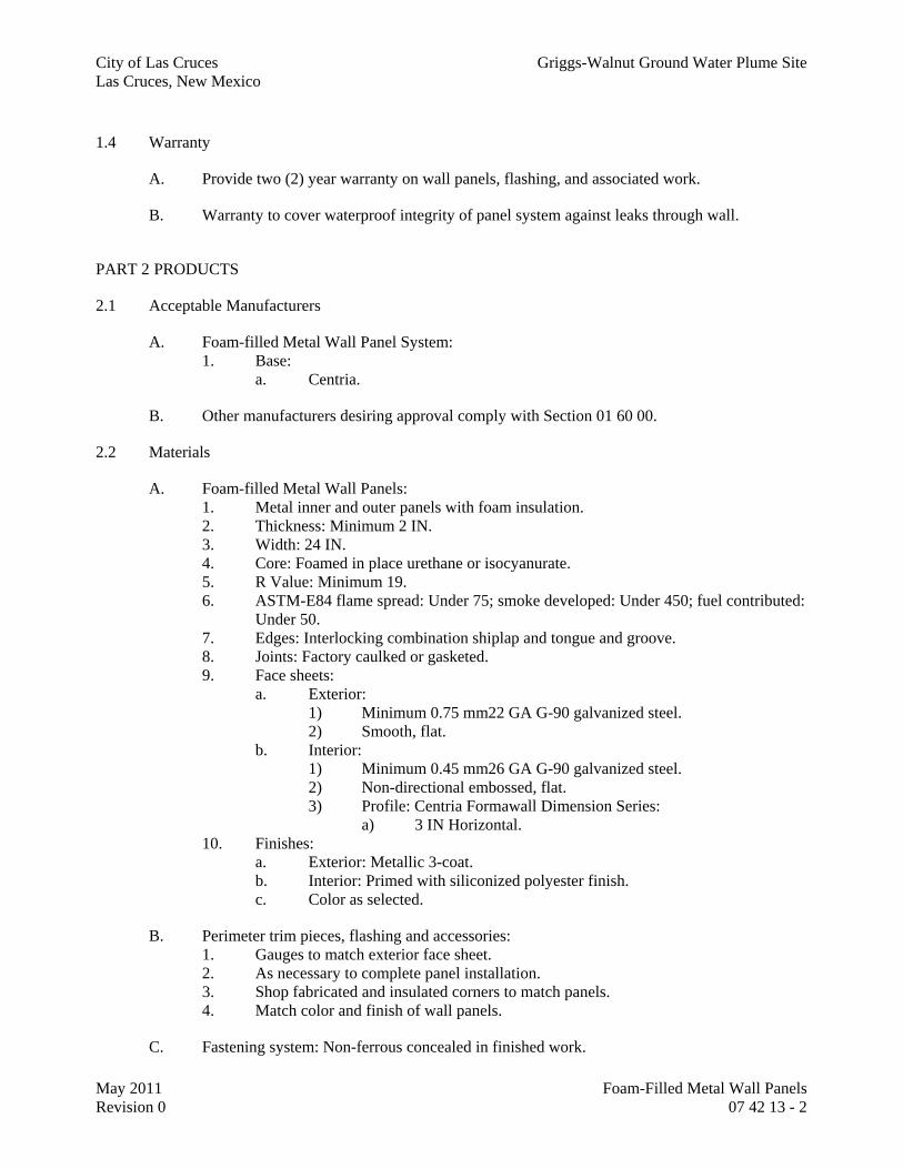
City of Las Cruces Griggs-Walnut Ground Water Plume Site Las Cruces, New Mexico
May 2011 Foam-Filled Metal Wall Panels Revision 0 07 42 13 - 2
1.4 Warranty
A. Provide two (2) year warranty on wall panels, flashing, and associated work.
B. Warranty to cover waterproof integrity of panel system against leaks through wall.
PART 2 PRODUCTS
2.1 Acceptable Manufacturers
A. Foam-filled Metal Wall Panel System: 1. Base:
a. Centria.
B. Other manufacturers desiring approval comply with Section 01 60 00.
2.2 Materials
A. Foam-filled Metal Wall Panels: 1. Metal inner and outer panels with foam insulation. 2. Thickness: Minimum 2 IN. 3. Width: 24 IN. 4. Core: Foamed in place urethane or isocyanurate. 5. R Value: Minimum 19. 6. ASTM-E84 flame spread: Under 75; smoke developed: Under 450; fuel contributed:
Under 50. 7. Edges: Interlocking combination shiplap and tongue and groove. 8. Joints: Factory caulked or gasketed. 9. Face sheets:
a. Exterior: 1) Minimum 0.75 mm22 GA G-90 galvanized steel. 2) Smooth, flat.
b. Interior: 1) Minimum 0.45 mm26 GA G-90 galvanized steel. 2) Non-directional embossed, flat. 3) Profile: Centria Formawall Dimension Series:
a) 3 IN Horizontal. 10. Finishes:
a. Exterior: Metallic 3-coat. b. Interior: Primed with siliconized polyester finish. c. Color as selected.
B. Perimeter trim pieces, flashing and accessories: 1. Gauges to match exterior face sheet. 2. As necessary to complete panel installation. 3. Shop fabricated and insulated corners to match panels. 4. Match color and finish of wall panels.
C. Fastening system: Non-ferrous concealed in finished work.

City of Las Cruces Griggs-Walnut Ground Water Plume Site Las Cruces, New Mexico
May 2011 Foam-Filled Metal Wall Panels Revision 0 07 42 13 - 3
D. Subgirts and supports: Z180 G60 galvanized subgirts and intermediate support items as required for installation. 1. Minimum 16 GA studs.
PART 3 EXECUTION
3.1 Inspection
A. Verify suitability of substrate to receive installation.
B. Installation constitutes acceptance of responsibility for performance.
3.2 Erection
A. Erect system complete, per reviewed shop drawings.
B. Erect with concealed fasteners, locking entire unit to structural supports to prohibit negative pulloff under design loads.
3.3 Water Test
A. Upon completion of installation: Test water penetration in accordance with AAMA Standard AAMA 501.2 “Specifications for Field Check of Metal Curtain Walls for Water Leakage.”
B. Test entire surface.
C. Repair leaks.
3.4 PROTECTION
A. Provide required temporary closures and flashings to maintain weather integrity, during and after erection.
END OF SECTION

Division 8

City of Las Cruces Griggs-Walnut Ground Water Plume Site Las Cruces, New Mexico
May 2011 Hollow Metal (HM) Doors and Frames Revision 0 08 11 13 - 1
SECTION 08 11 13
HOLLOW METAL (HM) DOORS AND FRAMES
PART 1 GENERAL
1.1 Summary
A. Furnish all labor, materials, tools, equipment, and services for all Hollow Metal Doors and Frames, as indicated, in accordance with provisions of Contract Documents.
B. Completely coordinate with work of other trades.
1.2 Quality Assurance
A. Hollow Door and Frame Standards: 1. ANSI/SDI-A250.4 for Physical Performance. 2. ANSI/SDI-A250.8 for Level, Model, and overall requirements.
B. Fire rated doors and frames: 1. Provide doors which are identical in materials and construction to units in door and
frame assemblies tested in accordance NFPA 252, NFPA 80, and UL10C (Positive Pressure).
2. Provide doors which are labeled and listed for ratings indicated by ITS – Warnock Hersey, UL or other testing and inspection agency acceptable to authorities having jurisdiction.
3. Physical label or approved marking shall be affixed to fire door or fire door frame, at an authorized facility as evidence of compliance with procedures of labeling agency.
4. Positive Pressure: a. Comply with Positive Pressure Requirements UL 10C, Category A. b. Provide "S" labels where required.
1.3 Submittals
A. Shop Drawings: 1. Door and frame schedule.
1.4 Warranty
PART 2 PRODUCTS
2.1 Acceptable Manufacturers
A. Hollow Metal Doors and Frames: 1. Base:
a. Steelcraft Manufacturing. 2. Optional:

City of Las Cruces Griggs-Walnut Ground Water Plume Site Las Cruces, New Mexico
May 2011 Hollow Metal (HM) Doors and Frames Revision 0 08 11 13 - 2
a. Curries. b. Ceco Door Products. c. Republic Doors and Frames.
2.2 MATERIALS
A. Steel sheet and strip: 1. Typical: ASTM-A568.
B. Corrosion-resistant coating: 1. Standard:
a. Hot-dip Galvannealed: ZF180 A60 per ASTM-A653. b. Minimum zinc-iron alloy coating: 180 G/M2 0.6 OZ/FT2.
2. Application: Provide above corrosion-resistant coating at all door and frame components where used at exterior and interior wet and humid locations as defined by following: a. Exterior openings:
1) Openings located in an exterior wall. 2) Openings that are exposed to weather even if protected by overhead
canopy. 3) Openings used to form either side of an entrance vestibule between
exterior and conditioned spaces. 4) All openings in parking structures and garages. 5) Openings used for roof access. 6) Openings to and from loading docks, trash collection and
compacting areas. b. Interior openings in “wet and humid” areas:
1) Openings to and from rooms with showers, tubs or pools. 2) Openings to and from loading docks, trash collection and
compacting areas.
C. Primer: 1. Doors and frames shall be cleaned, phosphatized and finished as standard with one
coat of baked-on rust inhibiting primer paint in accordance with ANSI A250.10. 2. Primer shall be suitable and compatible as base for specified finish paints.
D. Zinc-rich primer for repair of galvanized/galvannealed items: Galvilite by ZRC Worldwide.
E. Lead Sheet: 1. ASTM-B29. 2. Free from imperfections affecting performance.
2.3 General Requirements – Hollow Metal (HM) Doors
A. General: 1. Comply with ANSI/SDI A250.8.
B. Determination of performance level for each door: 1. In accordance with following schedule, use indicated level of HM door indicated for
its location, size and other listed criteria.

City of Las Cruces Griggs-Walnut Ground Water Plume Site Las Cruces, New Mexico
May 2011 Hollow Metal (HM) Doors and Frames Revision 0 08 11 13 - 3
a. Note: Not all items below may apply to subject project.
Schedule of HM Door Levels
Location Additional Criteria Use ANSI Level: Miscellaneous
Openings where each leaf is less than 1190mm
47 IN
Level 3 (Extra Heavy-
duty) Exterior Doors 1 (flush) Openings where one or
more of the leaves exceeds 1190mm 47 IN
Level 4 (Maximum-duty)
Galvanized / galvannealed, Thermally Insulated
Exterior Doors 1 (stile and rail)
All Level 3
(Extra Heavy-duty)
Galvanized / galvannealed, Thermally Insulated
Non-fire rated Level 3
(Extra Heavy-duty)
--
Fire rated Level 3
(Extra Heavy-duty)
Labeled as indicated (w/out astragal wherever possible)
Interior Doors
Wet / Humid Areas 2 Level 3
(Extra Heavy-duty)
Galvanized / galvannealed; Moisture-resistant core - Fire-
resistant were required General Notes: Refer to Door Schedule for indication of the Door Type (I.e. Width, Fire Rating, Flush vs. Stile & Rail, etc) Refer to Plans for door location (Exterior vs. Interior) Where Hurricane or Tornado-resistant openings are specified: Refer “ADDITIONAL REQUIREMENTS” for appropriate door/frame construction. Footnotes: 1. Refer to Part 2.2 for definition of “Exterior” locations. 2. Refer to Part 2.2 for definition of “Wet/Humid” locations.
C. Construction - Hollow Metal (HM) Doors: 1. Door Thickness:
a. 45mm 1-3/4 IN. 2. HM Door Level, per ANSI-A250.8:
a. Level 3, Extra Heavy-duty, physical performance Level A. 1) Face Sheet Thickness: 1.3mm 16 GA.
b. Level 4, Maximum-duty, physical performance Level A. 1) Face Sheet Thickness: 1.7mm 14 GA.
3. Typical Model, per ANSI-A250.8: a. Model 2, Seamless.
4. End closures at top and bottom of door: a. Top:
1) Flush closure top cap. Minimum Sheet thickness: 0.8mm 20 GA. b. Bottom:
1) Flush closure. Minimum Sheet thickness: 0.8mm 20 GA.

City of Las Cruces Griggs-Walnut Ground Water Plume Site Las Cruces, New Mexico
May 2011 Hollow Metal (HM) Doors and Frames Revision 0 08 11 13 - 4
5. Cores: a. Steel stiffeners where structurally required. b. Exterior Doors:
1) Thermally insulated cores. 2) Minimum R-value: 0.704 K x M2/W 4.0 DegF x H x FT2/BTU
when tested according to ASTM-C1363. 3) Exception: Fire resistant core where rating is indicated for exterior
doors. c. Interior doors:
1) Non-rated doors: Kraft honeycomb laminated to face sheets. 2) Rated doors: Fire resistant core as required by label. 3) Wet/Humid Areas: Moisture-resistant materials, fire resistant where
applicable. d. Specific materials used for above listed core types: Manufacturer’s option. e. Reinforce for Hardware.
6. Vertical Door Edges: a. Lock Stile Edges: Beveled 3.2mm per 50mm 1/8 IN per 2 IN.
1) Exception for inactive leaves: Fabricate inactive leaves with a square edge at the lock stile edge. Active leaves to be beveled per above.
b. Hinge Stiles Edge: Beveled 3.2mm per 50mm 1/8 IN per 2 IN. c. Exceptions for Double-Acting Doors: Provide convex, radiused edges at
lock stiles and hinge stiles.
D. Hardware Reinforcement: 1. Fabricate according to ANSI/SDI A250.6 with reinforcement plates from same
material as door face sheets. 2. Minimum thickness: As prescribed in ANSI/SDI A250.6; Upgrade as necessary for
conditions such as door weight, size, frequency, etc. and as follows: a. Butt Hinges: 4.4mm 7 GA. b. Continuous hinges: Reinforce with 1.7mm X 31.7mm 14 GA x1-1/4 IN
strapping extending full height and welded to hinge edge of door. c. Closers and Overhead Stops: 1.7mm 14 GA.
E. Lites: 1. Provide light kits which are labeled for intended opening. 2. Fixed Stop:
a. Locate at exterior face. b. Integral to door/frame.
3. Removable Stop: a. Locate on interior face. b. Screw-less snap-in stops or stops secured with countersunk Phillips head
machine screws.
F. Overlapping Astragals: 1. Provide approved overlapping astragals where required by label but not provided in
Section 08 71 00 / Hardware. 2. Weatherstripping: Specified in Section 08 71 00.
G. Lead Lined Astragals:

City of Las Cruces Griggs-Walnut Ground Water Plume Site Las Cruces, New Mexico
May 2011 Hollow Metal (HM) Doors and Frames Revision 0 08 11 13 - 5
1. Provide overlapping LL Astragals at meeting stiles of Lead-Lined Pairs. 2. Description: 2 plies of steel over one ply of 1.9mm 0.075 IN minimum sheet lead. 3. Utilize UL-listed items where opening is also fire-rated.
2.4 General Requirements – Hollow Metal (HM) Frames
A. General: 1. Comply with ANSI/SDI A250.8 and with details indicated for type and profile. 2. Fabricate frames with mitered or coped corners. 3. Touch-up galvanized/galvannealed frames with zinc-rich primer.
B. Fabricate frames as Face-Welded (modified ANSI definition): 1. Face Joints: Continuously back-weld face joints (weld on concealed side). 2. Fill and finish exposed sides to be free of visible seams. 3. Intersections of Rabbets, Stops and Soffit Joints: Fabricate to hairline joints. Stitch-
weld on concealed side. 4. Split type frames and knock-down type frames are not acceptable. 5. Fasteners which are exposed-to-view are not acceptable.
C. Determination of steel gauge for each frame: 1. Per following schedule, use the indicated minimum steel gauge as indicated for its
location, size and other listed criteria. 2. Note: Some of the items below may not apply to subject project.
Schedule of HM Frames
Location Criteria Minimum Gauge Miscellaneous Where overall width of
frame is less than 1194mm 47 IN
1.7mm 14 GA Exterior Frames
1 Where overall width of frame is greater than
1194mm 47 IN 2.5mm 12 GA
Galvanized / galvannealed
Non-fire rated 1.3mm 16 GA --- Fire rated 1.3mm 16 GA --- Interior Frames 1
Wet / Humid Areas 2 1.3mm 16 GA Galvanized / galvannealed
General Notes: Gauge of frame listed is "minimum". Use heavier gauge as required due to size, physical configuration or if required to meet fire label requirements. Refer to Door Schedule for indication of the Frame Type (I.e. Width, Single vs. Pair; Fire Rating, etc) Refer to Plans for door location (Exterior vs. Interior) Where Hurricane or Tornado-resistant openings are specified: Refer “ADDITIONAL REQUIREMENTS” for appropriate door/frame construction. Footnotes: 1. Refer to Part 2.2 for definition of “Exterior” locations. 2. Refer to Part 2.2 for definition of “Wet/Humid” locations.

City of Las Cruces Griggs-Walnut Ground Water Plume Site Las Cruces, New Mexico
May 2011 Hollow Metal (HM) Doors and Frames Revision 0 08 11 13 - 6
D. Lites: 1. Provide light kits labeled for intended opening. 2. Fixed Stop:
a. Locate at exterior face. b. Integral to door/frame.
3. Removable Stop: a. Locate on interior face. b. Screw-less snap-in stops or stops secured with countersunk Philips head
machine screws.
E. Silencers: 1. Specified in Section 08 71 00. 2. Quantity:
a. 3 on strike jamb of single frames. b. 2 per door for pair doors. Locate at head.
3. Space per manufacturer's recommendations. 4. Use plastic plugs to keep holes clear during construction.
F. Hardware Reinforcement: 1. Fabricate according to ANSI/SDI A250.6 with reinforcement plates from same
material as frames. 2. Minimum thickness: As prescribed in ANSI/SDI A250.6; upgrade as necessary for
conditions such as door weight, size, frequency, etc. and as follows: a. Butt Hinges: 4.2mm 7 GA. b. Continuous hinges: Reinforce with 1.7mm X 31.7mm 14 GA x1-1/4 IN
strapping extending full height and welded to hinge jamb door rabbet of frame.
c. Closers and Overhead Stops: 2.3mm thick X 300mm-long 12 GA thick x 12 IN-long strapping welded to vertical flange of frame.
G. Cover Boxes: 1. Material: 1.4mm 16 GA sheet steel. 2. Size and shape: As required by hardware device. 3. Include knock-out to receive 13mm 1/2 IN conduit. 4. Locate Cover Boxes in all frames scheduled to receive electrified Security or Door
Hardware devices or both. a. Devices including, but not limited to: Electric Strikes, Maglocks, Door
Position Switches, Current-conducting hinges, etc.
H. Jamb Anchors: 1. General:
a. Material: ASTM-A879 Commercial Steel, 12G 40Z coating; mill phosphatized. 1) Exception for frames built into exterior walls: Steel sheet complying
with ASTM-A1008 or ASTM-A1011, hot-dip galvanized according to ASTM-A153, Class B.
b. Provide anchors in accordance with manufacturer's recommendations on fire rated doors.
c. Provide minimum number as indicated on following Table:

City of Las Cruces Griggs-Walnut Ground Water Plume Site Las Cruces, New Mexico
May 2011 Hollow Metal (HM) Doors and Frames Revision 0 08 11 13 - 7
Jamb Anchors Minimum Quantity Required (per Jamb)
Nominal Frame Height Minimum Quantity per Jamb
Up to 1525mm 60 IN 2 Between 1525mm 60 IN and 2290mm 90 IN 3 Between 2290mm 90 IN and 3050mm 120
IN 4
Between 3050mm 120 IN and 3810mm 150 IN
5
Taller than 3810mm 150 IN Add 1 additional for each
762mm 30 IN increase in height thereafter
2. Jamb Anchors for Stud-Framed walls:
a. Z-shaped clips, welded to inside of frames; not less than 1.0mm thick. b. Attach anchors to studs with screws.
3. Jamb Anchors for Masonry walls: a. Adjustable strap-and-stirrup or T-shaped anchors to suit frame size, not less
than 1.0mm 18GA, with corrugated or perforated straps not less than 50mm 2 IN wide by 250mm 10 IN long; or wire anchors not less than 4.5mm 6GA thick.
b. Embed long leg into masonry wall as it is laid. 4. Post-installed Expansion Type for In-Place Concrete (or Masonry):
a. Minimum 9.5mm 3/8 IN countersunk, flat-head expansion bolts with expansion shields or inserts.
b. Include pipe spacer from frame to wall, with throat reinforcement plate, welded to frame at each anchor location.
c. Minimum embedment length: 45mm 1-3/4 IN.
I. Floor Anchors: 1. Material: Same for Jamb Anchors but not less than 1.4mm 0.053 IN (12 GA) thick. 2. For anchors built into exterior walls, steel sheet complying with ASTM-A1008 or
ASTM-A1011, hot-dip galvanized according to ASTM-A153, Class B. 3. Application:
a. Monolithic Concrete Slabs: Clip-type anchors, with two holes to receive fasteners.
b. Topped Slabs: Adjustable-type anchors with extension clips, allowing not less than 50mm 2 IN height adjustment. Terminate bottom of frames at finish floor surface.
4. Include concealed fasteners. 5. Provide anchors in accordance with manufacturer's recommendations on fire rated
doors.
J. Additional Head Anchors for Double Egress Frames: 1. Provide 2 frame anchors for Double Egress frames. 2. Locate at 1/3 rd points of span.
K. Spreaders: 1. Provide removable spreaders at bottom of door frames.

City of Las Cruces Griggs-Walnut Ground Water Plume Site Las Cruces, New Mexico
May 2011 Hollow Metal (HM) Doors and Frames Revision 0 08 11 13 - 8
L. Inserts, bolts and fasteners: 1. Manufacturer's standard units. 2. Galvanize items to be built into exterior walls ASTM-A153, Class C or D as
applicable.
M. Grout: 1. Portland cement-based grout mixture 2. Grout mixtures shall not contain gypsum.
2.5 Materials – Miscellaneous
A. Glass Pass-thru Hardware; where indicated to be installed in HM frames: 1. General:
a. Aluminum finish: Anodized natural finish aluminum components; corrosion resistant.
2. Sliding Door Assembly: a. Base Product: Roll-Ezy P992 ZC by Knape and Vogt. b. Assembly includes following components:
1) Bottom track: No. 999. 2) Carriers: No. 997.
a) Capacity: 20 LBS each. b) Provide 2 minimum; more if necessary to support panels
indicated. 3) Shoe: No. 995. 4) Upper channel: No. 993.
3. Other Hardware: a. Pull: KV-836. b. Ratchet Lock: KV-963, keyed as directed. c. Rubber bumpers: KV-1087; Provide at each jamb.
4. Glass: See Section 08 81 00 for type. a. Install glass into top guide and bottom shoe using glazing strip or silicone.
2.6 Fabrication
A. General: 1. Fabricate rigid, neat in appearance and free from defects. 2. Form to indicated sizes and profiles. 3. Fit and assemble in shop, wherever practical. 4. Mark work that cannot be fully assembled in shop, to assure proper assembly at site. 5. Door to Frame Clearances:
Door To Frame Clearances
Rated / Non-rated
Location Wood Doors Hollow Metal
Doors
Top Rail to Frame Lock Stile to Jamb Hinge Stile to Jamb
2.4 to 3.2mm 3/32 to 1/8 IN
2.4 to 4mm 3/32 to 5/32 IN
Rated Openings
Meeting Stiles at Pair Doors 1.64 to 3.2mm 1.64 to 3.2mm

City of Las Cruces Griggs-Walnut Ground Water Plume Site Las Cruces, New Mexico
May 2011 Hollow Metal (HM) Doors and Frames Revision 0 08 11 13 - 9
Face of door to face of Stop 1/16 to 1/8 IN 1/16 to 1/8 IN Typical; all floor covering
types Up to 12.7mm
1/2 IN Up to 12.7mm
1/2 IN
At Non-combustible SillsUp to 9.5mm 3/8
IN Up to 9.5mm
3/8 IN Door Bottom to Floor / Flooring
Bare floors; No flooring or sills
Up to 19mm 3/4 IN
Up to 19mm 3/4 IN
Non-rated Openings
All Conditions Comply with
criteria listed for rated openings
Comply with criteria listed for rated openings
a. Comply also with additional requirements of the following where more
stringent: 1) ANSI A250.8. 2) SDI 117. 3) Fire-rated doors: NFPA 80. 4) Smoke-Control Doors: NFPA 105. 5) Locally adopted Building Code.
B. Hardware Preparation: 1. Factory prepare hollow metal work to receive templated mortised hardware; include
cutouts, reinforcement, mortising, drilling, and tapping according to Door Hardware Schedule and templates furnished as specified in Section 08 71 00.
2. Locate hardware indicated, or if not indicated, according to ANSI/SDI A250.8. 3. Reinforce doors and frames to receive non-templated, mortised and surface-mounted
door hardware. 4. Comply with applicable requirements in ANSI/SDI A250.6 and
ANSI/DHI A115 Series specifications for preparation of hollow metal work for hardware.
5. Coordinate locations of conduit and wiring boxes for electrical connections with Division 26 Sections.
C. Remove mill scale and foreign materials, touch-up damaged galvanized or galvannealed surfaces.
D. Hollow Metal Doors: 1. Exterior Doors: Provide weep-hole openings in bottom of exterior doors. 2. Seal joints in top edges of doors against water penetration. 3. Glazed Lites: Factory cut openings in doors. 4. Astragals: Provide overlapping astragal on one leaf of pairs of doors where required
by NFPA 80 for fire-performance rating or where indicated.
E. Prime: 1. Shop prime.
F. Fire Labels: 1. Affix permanent labels to fire rated units in accordance with testing agency
requirements.

City of Las Cruces Griggs-Walnut Ground Water Plume Site Las Cruces, New Mexico
May 2011 Hollow Metal (HM) Doors and Frames Revision 0 08 11 13 - 10
2. At openings where continuous hinges, or other items when scheduled and installed would conceal fire label, locate labels on alternative locations as allowed by listing agency and local authorities.
G. Prepare frames for Door Position Switches (DPS): 1. Coordinate locations with Security System provider. 2. Locate DPS frame head approximately 100mm 4 IN from latching door edge.
PART 3 EXECUTION
3.1 Inspection
A. Examine structure, substrates, and conditions under which work is to be installed for conditions detrimental to correct and timely completion.
B. Installation constitutes acceptance of responsibility for performance.
3.2 Installation Quality Control
A. Initially set frames plumb, level and square within allowable tolerances.
B. Verify plumb, level and square after walls are set and make adjustments where required.
C. Verify plumb, level and square again just prior to hanging doors, making adjustments as required. Insure that door-to-frame clearances are within specified tolerances.
3.3 Installation
A. General: 1. Install steel doors, frames, and accessories in accordance with approved shop
drawings, manufacturer's data, and as specified. 2. Place frames prior to construction of enclosing walls and ceilings. 3. Coordinate building in of anchors, and frame grouting with other trades.
B. Placing Frames: 1. General:
a. Comply with provisions in ANSI A250.11/ SDI 105, unless otherwise indicated.
b. Install fire-rated frames according to NFPA 80. 2. Place frames before construction of adjacent walls.
a. Exception: Where adjacent walls are cast-in-place concrete: Set frames ‘after’ wall is constructed.
3. Set frames accurately in position, plumbed, aligned, and braced securely. 4. Adjust hollow metal door frames for squareness, alignment, twist, and plumb to the
following tolerances: a. Plumb: Plus or minus 1.6mm 1/16 IN, measured at jambs at floor. b. Level: Plus or minus 1.6mm 1/16 IN per leaf, measured across width of
header.

City of Las Cruces Griggs-Walnut Ground Water Plume Site Las Cruces, New Mexico
May 2011 Hollow Metal (HM) Doors and Frames Revision 0 08 11 13 - 11
c. Square: Plus or minus 1.6mm 1/16 IN, measured at door rabbet on a line 90 degrees from jamb perpendicular to frame head.
d. Alignment: Plus or minus 1.6mm 1/16 IN, measured at jambs on horizontal line parallel to plane of wall.
e. Twist: Plus or minus 1.6mm 1/16 IN, measured at opposite face corners of jambs on parallel lines, and perpendicular to plane of wall.
5. Do not remove spreaders until surrounding wall construction is complete. 6. After surrounding walls have been constructed, verify that frames are still in proper
alignment. a. Re-check for level, plumb, square, twist and other problems that will
prevent proper fitting of doors. b. Correct deficiencies before surrounding construction is allowed to proceed. c. Work with wallboard installer, if necessary, to correct misalignment
problems. 7. After wall construction is completed, remove temporary braces and spreaders,
leaving surfaces smooth and undamaged. 8. Prior to hanging doors: Verify all aspects of frame alignment, and correct
deficiencies. 9. Install frames with removable glazing stops located on secure side of opening. 10. Install door silencers in frames before grouting. 11. Field apply bituminous coating to backs of frames that are filled with grout.
C. Frame-to-Wall Anchors: 1. Utilize anchor type specified for wall condition. 2. Align anchors at hinge centers on hinge jamb and at corresponding heights on strike
jamb. 3. Secure frame to wall per manufacturer’s instructions.
D. Grout all frames set into Cast-in-Place Concrete, CMU, and other masonry walls. 1. Do not grout frames set into metal stud-framed wall types.
E. Door Installation: 1. Comply with ANSI A250.8. 2. Fit hollow-metal doors accurately in frames, within clearances specified. 3. Shim as necessary to comply with SDI 122 and ANSI/DHI A115.1G.
F. Prime-Coat Touchup: 1. Immediately after erection, sand smooth rusted or damaged areas of primer coat. 2. Touch up primer coat with compatible air-drying primer. 3. Leave surfaces smooth for finish painting.
G. Field Painting of HM Frames and Doors: 1. Painting of Exterior openings: Specified in Section 09 91 23. 2. Painting of Interior openings: Specified in Section 09 91 23. 3. Do not paint factory pre-finished doors such as stained faux wood (embossed steel)
doors.
H. Install Sealants: 1. Sealant

City of Las Cruces Griggs-Walnut Ground Water Plume Site Las Cruces, New Mexico
May 2011 Hollow Metal (HM) Doors and Frames Revision 0 08 11 13 - 12
a. Exterior Sealants: ASTM-C920 Type S or M, Grade-NS, minimum Class-25. 1) Sealant Type: Multi-part Polyurethane, chemically curing,
epoxidized 2) Base Product: Tremco "Dymeric 240FC"
b. Interior Sealants: ASTM-C920 Type S or M, Grade-NS, minimum Class-25. 1) Sealant Type: Siliconized Acrylic Latex (paintable) 2) Base Product: Tremco "Tremflex 834"
2. Seal frames to walls. 3. Seal frames to floor slabs and hard floor finishes. 4. Hairline gap at intersections of head and jamb frames (intersections of rabbets and
stops): a. Fill exposed seam with painter’s caulk.
I. Install silencers.
3.4 Adjusting and Cleaning
A. Alignment: 1. After surrounding walls have been constructed, verify frames are remain in proper
alignment. 2. Check for level, plumb, square, twist and other problems that will prevent proper
fitting of doors. 3. Correct deficiencies before surrounding construction is allowed to proceed.
B. Protection Removal: 1. Immediately before final inspection, remove protective wrappings from doors and
frames.
C. Leave work complete and in proper operating condition.
D. Remove and replace defective work.
E. Ensure that all fire labels are intact, and readily visible.
END OF SECTION

City of Las Cruces Griggs-Walnut Ground Water Plume Site Las Cruces, New Mexico
May 2011 Overhead Coiling Doors Revision 0 08 33 23 - 1
SECTION 08 33 23
OVERHEAD COILING DOORS (CD)
PART 1 - GENERAL
1.1 SUMMARY
A. Furnish all labor, materials, tools, equipment, and services for all Overhead Coiling Doors, as indicated, in accordance with provisions of Contract Documents.
B. Completely coordinate with work of other trades.
C. Coiling Door (CD) types. Refer to Overhead Door Schedule for indication of each type to be used. 1. CD-IS: Coiling Door - Insulating Slat. 2. CD-NR: Coiling Door - Non-Rated.
D. Coordinate electrical hookups with Electrical Specification Divisions.
1.2 SUBMITTALS
A. Shop Drawings.
B. Project Information: 1. Certificate of UL construction.
C. Contract Closeout Information: 1. Operating and maintenance data. 2. Owner instruction report. 3. Warranty.
1.3 WARRANTY
A. Manufacturer’s standard two (2) year warranty covering repair or replacement resulting from defects in material or workmanship.
PART 2 - PRODUCTS
2.1 ACCEPTABLE MANUFACTURERS
A. Overhead doors: 1. Base:
a. Cornell. 2. Optional:
a. Cookson. b. McKeon. c. North American Rolling Door, Wayne Dalton. d. Overhead Door. e. Raynor.
B. Other manufacturers desiring approval comply with Section 01 60 00.

City of Las Cruces Griggs-Walnut Ground Water Plume Site Las Cruces, New Mexico
May 2011 Overhead Coiling Doors Revision 0 08 33 23 - 2
2.2 COILING DOORS – GENERAL CRITERIA
A. See Overhead Door Schedule in Sheet A06: 1. Door height(s) and width(s). 2. Coiling Door Type. 3. Rating requirements. 4. Other information unique to each opening.
B. Curtain: 1. 50 – 75mm 2 – 3 IN tall slats, interlocked to form an upward coiling curtain. 2. Nominal Thickness: 19mm 3/4 IN. 3. Gauge as determined by application, wind load, door width, and materials. 4. Type of material and finish as indicated for each door. 5. Typical Slat Style(s):
a. Non-insulated doors (CD-NR & CD-FR types): 1) Flat face, Cornell type 5F, unless otherwise indicated.
b. Insulated doors (CD-IS): 1) Double wall slats injected with polyurethane foam. 2) Thickness: 23mm 15/16 IN. 3) Thermal Value: RSI/m=4.8 R=6.25 minimum. 4) Slat Type: Cornell 6F.
6. Endlocks: a. Minimum requirement: Provide malleable iron endlocks at each end of alternating slats to
act as a wearing surface and to maintain slat alignment.
C. Bottom Bar: 1. Curtain to be reinforced with bottom bar consisting of 2 back-to-back angles. 2. Material and Finishes: As indicated for each door type, generally matching the curtain material
and finish. 3. Neoprene bottom seal to protect floor surface at sill.
a. Except where Safety Edge is indicated. 4. Where floor surface slopes across width of opening: Fabricate bottom bar to match floor slope. 5. Notch for obstructions where indicated or as required.
D. Bracket plates: 1. Minimum thickness: 1/4 IN. 2. Fitted with sealed ball bearing on drive end. 3. Material and Finishes as indicated for each door type.
E. Spring counterbalance: 1. Housed in a steel pipe of diameter and wall thickness to limit maximum deflection to 2.5mm/M
0.03 IN/FT. 2. Springs: Helical torsion type designed to include and overload factor of 25% and for optimal
ease of operation. a. Motorized Doors: Utilize High Cycle springs rated at 100,000 cycles.
3. Springs to be grease-packed and mounted on a cold-rolled steel inner shaft. 4. Spring Tension: adjustable from end of bracket plate. 5. Include safety device that prevents free fall of curtain in any position, in the event of failure of
an operating mechanism. 6. Sealed ball bearings to minimize wear of pipe shaft rotation around inner shaft.

City of Las Cruces Griggs-Walnut Ground Water Plume Site Las Cruces, New Mexico
May 2011 Overhead Coiling Doors Revision 0 08 33 23 - 3
F. Mounting: 1. Typical configuration:
a. Face of wall (inside). b. Unless otherwise indicated for each door type.
G. Guide angles and wall angle assemblies: 1. Minimum thickness: 3/16 IN. 2. Provide adequate overlap of guide flanges over curtain to satisfy design windload. 3. Material and Finishes: As indicated for each door type. 4. Include removable section on coil side for installation and service.
a. Exception: Omit requirement where Stainless Steel or Aluminum guides are specified.
H. Hood: 1. Typical profile:
a. Round. b. Except where noted otherwise.
2. Reinforce to prevent sag. 3. Include intermediate hood supports where door width exceeds 16 FT. 4. Material and Finishes: As indicated for each door type. 5. Include neoprene hood baffle at doors used on the exterior. 6. Include Flame Baffle at Fire Rated openings.
2.3 EXTERIOR DOORS – SPECIFIC CRITERIA
A. Design Exterior doors to meet Design Wind Load. 1. Design wind load pressure: 20 PSF minimum.
B. Weather Seals: 1. Bottom Bar Seal:
a. Motorized doors with safety edge: Combination electric safety edge device and weatherseal.
b. Non-motorized doors: Manufacturer’s standard neoprene astragal seal at bottom bar. 2. Guide weatherstripping which seals against the exterior face of slats. 3. Neoprene hood baffle. 4. Air infiltration: Maximum 1.5 L/s/M 1 CFM/FT of perimeter.
C. Windlocks: 1. Provide windlocks on all doors used in an Exterior wall, regardless of width. 2. Provide roller windlocks and roller endlocks where door width exceeds 12 FT- 4 IN.

City of Las Cruces Griggs-Walnut Ground Water Plume Site Las Cruces, New Mexico
May 2011 Overhead Coiling Doors Revision 0 08 33 23 - 4
2.4 MATERIALS & FINISHES – GALVANIZED/STEEL (G/S) UNITS
Materials and Finishes for Galv/Steel (G/S) Coiling Units
Component Item Material 2 Primer 2 Finish
Curtain Slats Galv Steel Baked-on Primer Powder Coat Bottom Bar Galv Steel Baked-on Primer Powder Coat
Wall/Guide Angles Ferrous Steel Shop Coat Primer Paint in Field Hood Ferrous Steel Shop Coat Primer Paint in Field
End Bracket Plates Ferrous Steel Shop Coat Primer Paint in Field Fascia 1 Ferrous Steel Shop Coat Primer Paint in Field
Footnotes: 1. Where Fascias are required. 2. Upgrade components which are exposed to weather to "Galv Steel" and "Baked-on Primer".
A. Definition of items indicated in above Table: 1. Material:
a. Galvanized Steel, ASTM-A653 Z275 G90. 2. Primer:
a. Baked-on Primer: Epoxy-modified polyester, applied at factory. 1) Use on galvanized components.
b. Shop coat primer: Rust-inhibiting primer, applied at factory. 1) Use on non-galvanized components.
3. Factory Finishes: a. Powder Coat: Factory-applied Powder Coat.
1) Color(s) to be selected by Architect. 4. Field-painted items:
1) Specified in Section 09 91 23 (for interior doors).
2.5 OPERATION – MANUAL TYPES
A. Hand Chain (HC): 1. Manually operated galvanized chain loop utilizing gear reduction. 2. Pull force required: Not to exceed 35 LBS.
B. Awning Crank (AC): 1. Removable crank. 2. Gear reduction.
C. Waist-height hand Crank (WC): 1. Removable crank. 2. Gear reduction.
D. Manual push-up (MPU): 1. Provide lift handle on coil-side. 2. Force required: Not to exceed 25 LBS.
E. Locking of manual operation types: 1. Cylinder lock on bottom bar.
a. Cylinder(s) as specified in Section 08 71 00.

City of Las Cruces Griggs-Walnut Ground Water Plume Site Las Cruces, New Mexico
May 2011 Overhead Coiling Doors Revision 0 08 33 23 - 5
F. Fire-rated Manual Doors: 1. Provide basic fire protection. 2. Slow, safe, controlled decent not exceeding 230mm/Sec 9 IN/Sec. 3. Activated by:
a. Local smoke/head detection. 4. Fail Safe operation. 5. Easily re-set by Owner staff. 6. Base Product: “M100 FireGard Chain/Crank-Operated System” by Cornell.
PART 3 - EXECUTION
3.1 INSPECTION
A. Verify that dimensions are correct. 1. Resolve any discrepancies between “design” dimensions and “actual” dimensions.
B. Verify suitability of substrate and opening to accept installation.
C. Installation constitutes acceptance of substrate and responsibility for performance.
3.2 INSTALLATION
A. By manufacturer or authorized representative.
B. Prior to occupancy, adjust door for smooth operation.
END OF SECTION

City of Las Cruces Griggs-Walnut Ground Water Plume Site Las Cruces, New Mexico
May 2011 Aluminum Windows – Thermal Revision 0 08 51 10 - 1
SECTION 08 51 10
ALUMINUM WINDOWS - THERMAL
PART 1 - GENERAL
1.1 SUMMARY
A. Furnish all labor, materials, tools, equipment, and services for all Aluminum Windows - Thermal, as indicated, in accordance with provisions of Contract Documents.
B. Completely coordinate with work of other trades.
1.2 QUALITY ASSURANCE
A. Qualifications: Window manufacturer to provide written confirmation that installer is authorized to install window products used on this project.
B. In-Plant Testing: Conduct detailed quality audits and ASTM E331 static water infiltration testing on a minimum of 4% of factory-glazed windows prior to shipping.
C. Each tested unit shall be identified with a removable sticker on the inside glass face.
D. Provide detailed documentation of in-plant testing.
1.3 TEST REQUIREMENTS
A. Manufacturers requesting approval submit test data with request.
B. Test unit: 1. Largest size window unit for project, with largest ventilator, or minimum test size outlined in
AAMA GS-001. 2. Completely assembled and glazed as specified. 3. Install in test chamber to simulate and be in accordance with installation details to be used on
project.
C. Alternate test unit: Same as test unit except as follows: 1. As required by AAMA 1502.7, 1220 x 1830 mm 4 x 6 FT. 2. Unit need not be identical, but must comply as follows:
a. Same thickness of frame section (front to back). b. Identical thermal break. c. Same basic metal mass on outside. d. Same type of glazing.
3. Submit information necessary to prove Alternate Test Unit complies in above respects.
D. Test air infiltration first, water resistance second.
E. Air infiltration test: 1. With sash and ventilators closed and locked, test in accord with ASTM-E283. 2. Air infiltration: 0.15 L/s/m 0.10 CFM/FT of crack length, at pressure differential of 300 Pa
6.24 PSF.

City of Las Cruces Griggs-Walnut Ground Water Plume Site Las Cruces, New Mexico
May 2011 Aluminum Windows – Thermal Revision 0 08 51 10 - 2
F. Water resistance test: 1. Mount glazed unit in its vertical position, continuously supported around outside perimeter
with sash and ventilators closed and locked. 2. Test in accordance with ASTM-E331. 3. No uncontrolled leakage allowed with pressure differential of 385 Pa 8.00 PSF.
G. Uniform load deflection test: 1. Test in accordance with ASTM-E330. 2. Subject unit to load as outlined below applied to outside and inside of window. 3. Maximum allowable deflection unsupported span: L/175. 4. No glass breakage, permanent damage to fasteners, hardware parts, support arms, activating
mechanisms, or other damage which would cause window to be inoperable.
H. Uniform load structural test: 1. Uniform Load Deflection Test:
a. No deflection of any unsupported span L of test unit (framing rails, muntins, mullions, etc.) in excess of L/175 at both a positive and negative load of 70 PSF (design test pressure) when tested in accord with ASTM E330.
2. Uniform Load Structural Test: a. Unit to be tested at 1.5 x design test pressure, both positive and negative, acting normal to
plane of wall in accord with ASTM E330. b. No glass breakage; permanent damage to fasteners, hardware parts, or anchors; damage to
make windows inoperable; or permanent deformation of any main frame or ventilator member in excess of 0.2% of its clear span.
3. Design unit to withstand design pressures as required by applicable building codes.
I. Condensation resistance test: 1. Perform on Test Unit or Alternate Test Unit. 2. Test in accordance with AAMA 1502.7. 3. CRF minimum value:
a. Glass: 50. b. Frame: 53.
J. Thermal test: 1. Perform on Test Unit except size may be 1220 x 1830 mm 4 x 6 FT, minimum. 2. Test in guarded hot box facility in accordance with ASTM-C1363 and AAMA-1503.1, with an
exterior temperature of minus 8 degC 18 degF, an interior of 20 degC 68 degF and 24 km/h 15 MPH fan generated wind velocity on exterior.
3. "U" value: Not to exceed 3.7 W/m2K 0.65 BTU/HR/SF/degF. 4. Calculated "U" values from smaller units or data or theoretical assumptions will not be
acceptable.
K. Structural thermal barrier tension test: 1. Test urethane filled, debridged, sections of aluminum. 2. Mechanically secure interior and exterior faces of 12 IN section in horizontal position. 3. Apply heat tape to exterior face to control surface temperature at 180 degF five minutes before
loading, as indicated by a thermocouple wire operated by an automatic controller. 4. Apply direct tension (pull) using a Universal Testing machine set in 12,000 LB load range. 5. Test results: No loss of bond at 5,000 LB load with load applied at a strain rate of 0.05 IN/IN/MIN.

City of Las Cruces Griggs-Walnut Ground Water Plume Site Las Cruces, New Mexico
May 2011 Aluminum Windows – Thermal Revision 0 08 51 10 - 3
L. Structural thermal barrier shear test: 1. Test urethane filled, debridged, sections of aluminum. 2. Mechanically secure interior face of 12 IN section in vertical position. 3. Apply heat tape to exterior face to control surface temperature at 180 degF five minutes before
loading, as indicated by a thermocouple wire operated by an automatic controller. 4. Apply load to exterior face by a bearing plate resting on top of exterior face. 5. Apply shear using a Universal Testing machine set in 12,000 LB load range at a strain rate of
0.050 IN/IN/MIN. 6. Test results: No loss of bond at 3,500 LB loading.
M. Ventilator corner load tests: 1. Test each type of ventilator, by loading with a Universal Testing machine. 2. Vent corner must indicate no appreciable elongation up to a yield force of 6,250 LB.
N. Field check for water leakage: 1. Test water penetration in accordance with AAMA Standard AAMA 502 "Specifications for
Field Check of Aluminum Windows Walls for Water Leakage". a. Mockup wall. b. Actual installation (start of installation):
1) Test 3 windows. 2) Test locations as directed by Architect.
c. Actual installation (completion of installation): 1) Test 3 windows. 2) Test locations as directed by Architect.
O. Casement: 1. Casement vertical deflection:
a. Test completely assembled window, ventilator without muntins, glazed, with specified hardware.
b. Apply 60 LB concentrated load acting at lower unrestrained corner of ventilator opened at 90 degrees.
c. Vertical deflection at lower unrestrained corner: Maximum 1:200 of vent width. d. At conclusion of test, ventilator shall operate properly.
2. Casement hardware: a. Securely fasten window having two ventilators in vertical plane so when both ventilators
are opened to their fullest extent they will be horizontal. b. Apply uniform load of 6.24 PSF. c. At conclusion of test operators shall satisfactorily close and be weathertight. d. No failure of hardware, screws, track or permanent deformation of arm.
3. Casement torsion: a. Test ventilator without muntins and unglazed. b. Support ventilator on fulcrums at diagonally opposite corners, with a corner diagonally
opposite loaded corner secured in same plane. c. Apply 20 LB concentrated load, acting at unrestrained corner of ventilator. d. Deflection at unrestrained corner: Maximum 0.1875A (A is area, in square meters feet, of
ventilator being tested).
1.4 SUBMITTALS
A. Shop drawings: 1. Elevations, sections and details for review of support system to building frame.

City of Las Cruces Griggs-Walnut Ground Water Plume Site Las Cruces, New Mexico
May 2011 Aluminum Windows – Thermal Revision 0 08 51 10 - 4
B. Samples: 1. Range samples of aluminum finishes.
C. Project information: 1. Structural calculations prepared by a registered structural engineer made by or for window
manufacturer in connection with supplementary design and detailing of work for review of interface between window support system and building structural frame.
2. Certified independent laboratory test reports verifying requirements.
D. Contract closeout information: 1. Warranty. 2. Maintenance data.
1.5 WARRANTY
A. Written five (5) year warranty signed jointly by manufacturer and installer, agreeing to repair or replace work performed under this section which fails. 1. Failure includes but not limited to, defects in materials, workmanship, water tightness of
assembly, caulking, glazing or other defect which affects its ability to perform as a weathertight envelope.
PART 2 - PRODUCTS
2.1 ACCEPTABLE MANUFACTURERS
A. Aluminum windows: 1. Base:
a. Wausau Window and Wall Systems. 2. Optional:
a. Kawneer.
B. Other manufacturers desiring approval comply with Section 01 60 00 and paragraph Test Requirements.
2.2 MATERIALS
A. Model: 1. Wausau Metals, 2250T Series.
B. Extruded aluminum: 6063T5 alloy.
C. Glass: As specified in Section 08 81 00.
D. Sealants: 1. Exterior Sealants: ASTM-C920 Type S or M, Grade-NS, minimum Class-25. 2. Sealant Type: Multi-part Polyurethane, chemically curing, epoxidized 3. Base Product: Tremco "Dymeric 240FC" 4. Exposed sealants: Match color of aluminum.
E. Thermal insulator: 1. Poured in place polyurethane, self-adhering to adjacent aluminum surfaces. 2. Provide a minimum of 1/4 IN separation between exterior and interior metal surfaces after
bridge is removed.
F. Vertical pivot frames and operating sash:

City of Las Cruces Griggs-Walnut Ground Water Plume Site Las Cruces, New Mexico
May 2011 Aluminum Windows – Thermal Revision 0 08 51 10 - 5
1. Miter members at corners. 2. Fasten together by use of a corner block and permanently join by mechanical means, chemical
or heliarc welding on nonexposed surfaces, leaving only hairline joinery. 3. Seal weathertight. 4. Do not use joinery methods which discolor finish.
G. Weatherstripping vertical pivot windows: 1. Provide 2 rows of continuous neoprene weatherstrips, fin or bulb type, extending around
perimeter of sash. 2. Mold or vulcanize corners to form one piece easily replaceable unit.
H. Window frames (casement, top hinged inswinging, and projected): 1. Cope and mechanically fasten together at corners, or Miter at corners and heliarc weld on
nonexposed surfaces, leaving only hairline joinery. 2. Seal weathertight. 3. Do not use joinery methods which discolor finish. 4. Continuous vinyl starter.
I. Operating sash: 1. Miter members at corners. 2. Fasten together by use of a corner block and permanently join by mechanical means, chemical
or heliarc welding on nonexposed surfaces, leaving only hairline joinery. 3. Seal weathertight. 4. Do not use joinery methods which discolor finish.
J. Weatherstripping (casement, top hinged inswinging and projected): 1. Provide 2 rows of fin or bulb type extruded neoprene weatherstrips extending around perimeter
of sash at both inner and outer overlap contacts. 2. Provide securely staked and joined corners. 3. Provide replaceable units.
K. Window hardware - general: 1. Locking device and strikes: White bronze or non-magnetic stainless steel. 2. Hardware elements that bridge sash or frame thermal barrier: Reinforced Nylon, Delrin or
suitable non-metallic, low conductivity material. 3. Custodial key operation: Secure sash in closed position and automatically lock in washing
position. 4. Safety keys removable only in closed, locked, position.
L. Window hardware, casement: 1. Extension or butt hinges for roto-operated windows. 2. Concealed, 300 series, stainless steel 4 bar friction hinges for manually operated windows. 3. Two locks for ventilators greater than 1220 mm 4 FT in height. 4. Where upper lock in more than 1830 mm 6 FT above floor, provide double grip hardware
which activates both locks from lower device. 5. Roto operators: Tested in accordance with ASTM-E405, method A. Remove handles for tests.
a. At 500 cycles: Operating moment: 13.2 Nm 120 LBF-IN; closing torque: 0.66 Nm 60 LBF-IN.
b. At 7500 cycles: Operating moment: 6.6 Nm 60 LBF-IN; closing torque: 0.66 Nm 60 LBF-IN.
M. Glass: 1. See Section 08 81 00 for types of glass to be installed.

City of Las Cruces Griggs-Walnut Ground Water Plume Site Las Cruces, New Mexico
May 2011 Aluminum Windows – Thermal Revision 0 08 51 10 - 6
2. Provide glass capable of withstanding windloads in accord with ANSI/ASME 7-88. 3. Provide heat strengthened and tempered glass where it is determined by glass manufacturer
that these types of glass are necessary to withstand these loads.
N. Screens: 1. Aluminum wire mesh, ASTM-E2016. 2. Openings: 0.04 IN. 3. Secure to aluminum shapes with vinyl spline. 4. Hold in place with spring loaded plungers. 5. Removable to inside of building. 6. Finish same as window frames.
2.3 ANODIC FINISHES
A. General: 1. Color consistency range: 5 delta E’s. 2. Anodic Finish complying with AAMA 611 and the following:
B. Clear Anodic finish (Class I): 1. Architectural Class I per AAMA 611.
a. 2-step electrolytic. 2. Minimum Coating Thickness: 0.7 mils. 3. Color: “#14”, Clear, AA-M12C22-A41.
PART 3 - EXECUTION
3.1 INSTALLATION
A. Use only skilled tradesmen and in accordance with approved shop drawings.
B. Plumb and align nominal face of windows in a single plane for each wall plane.
C. Erect units square and true to insure proper alignment of openings.
D. Adjust operating sash for proper operation after installation.
E. Provide FSK vapor barrier tape between window perimeter and adjoining collateral materials and existing wall vapor barrier to assure continuity.
F. Do not anchor windows to brick.
G. Furnish and apply sealants to provide a weathertight installation at construction joints and at perimeter.
H. Wipe off excess material and leave surfaces and joints smooth.
3.2 FIELD QUALITY CONTROL
A. Field Tests - General: 1. Architect shall select Aluminum Windows to be tested when representative portion of
Aluminum Windows have been installed, glazed, perimeter caulked and cured. 2. Test for water penetration in accordance with AAMA 501.2-03, Quality Assurance and
Diagnostic Water Leakage Field Check of Installed Storefronts, Curtain Walls, and Sloped Glazing Systems.

City of Las Cruces Griggs-Walnut Ground Water Plume Site Las Cruces, New Mexico
May 2011 Aluminum Windows – Thermal Revision 0 08 51 10 - 7
3. Where test results do not meet requirements: Correct deficiencies, and implement improved installation procedures for completing balance of Storefront.
3.3 ADJUST AND CLEAN
A. At completion of project, adjust windows for proper operation, recheck installation, weathersealing, sealants and other items of complete installation.
B. Completely clean glass and metal surfaces and remove labels before final acceptance.
END OF SECTION

City of Las Cruces Griggs-Walnut Ground Water Plume Site Las Cruces, New Mexico
May 2011 Door Hardware Revision 0 08 71 00 - 1
SECTION 08 71 00
DOOR HARDWARE
PART 1 - GENERAL
1.1 QUALITY ASSURANCE
A. Fire-Rated Door Assemblies: 1. Where fire-rated door assemblies are indicated, provide door hardware rated for use in
assemblies complying with NFPA 80 that are listed and labeled by a qualified testing agency, for fire-protection ratings indicated, based on testing at positive pressure according to NFPA 252 or UL 10C, unless otherwise indicated.
B. Smoke- and Draft-Control Door Assemblies: 1. Where smoke- and draft-control door assemblies are required, provide door hardware that
meet requirements of assemblies tested according to UL 1784 and installed in compliance with NFPA 105.
2. Air Leakage Rate: Maximum air leakage of 3 CFM/FT2 0.015424 m3 per second/m2 at the tested pressure differential of 0.1 IN 24.9 Pa of water.
C. Finish designations and standards: Builders Hardware Manufacturers Association (BHMA) Standard 1301.
1.2 QUALIFICATIONS
A. Installer qualifications: Supervised or inspected by certified Architectural Hardware Consultant (AHC).
B. Hardware Supplier: 1. Recognized architectural door hardware supplier, with warehousing facilities, who has been
furnishing hardware in the project’s vicinity for a period of not less than 2 years. 2. On-staff, experienced Architectural Hardware Consultant (AHC) who is available, during
the course of the Work, for consultation about project’s hardware requirements.
C. Electrified Hardware Supplier: 1. Experienced door hardware supplier who has completed projects with electrified door
hardware similar in material, design and extent to that indicated for this project, who has a record of successful in-service performance and is acceptable to manufacturer of materials.
2. Shall prepare data for electrified door hardware based on testing and engineering analysis of manufacturer’s assemblies similar to those in this project.
1.3 SUBMITTALS
A. Shop Drawings: 1. Complete Hardware Schedule by door.
a. Complete list of products including model numbers and cut sheets. b. Hardware Schedule shall utilize Heading Numbers which are logically derived from
Architect’s Hardware Set numbers. c. Hardware Sets shall follow the guidelines established in Door & Hardware Institute
Handbook (DHI) Sequence and Format for the Hardware Schedule with index of doors and headings, indicating complete designations of every item required for each door or opening.
2. Diagrammatic Elevations and Point-to-Point Wiring Diagrams of openings scheduled to receive electrified hardware and electronic access control devices. a. Submit with Hardware Schedule.

City of Las Cruces Griggs-Walnut Ground Water Plume Site Las Cruces, New Mexico
May 2011 Door Hardware Revision 0 08 71 00 - 2
B. Project Information: 1. Certification that items bear UL label where required. 2. Meeting minutes from Pre-Installation Conference.
C. Contract Closeout Information: 1. Schedule of all components installed as hardware sets for each opening. 2. Operating and maintenance data.
a. Parts catalog for each product furnished. b. Keying records.
3. Owner instruction report. 4. Letter stating extra material has been delivered.
1.4 PRODUCT DELIVERY, STORAGE AND HANDLING
A. Tag or package each item identified to hardware schedule.
B. Include installation instructions.
C. Deliver hardware items at times and to locations as directed.
D. Check hardware against schedule, reorder missing items.
E. Control items before and after installation so completion will not be delayed by hardware losses.
F. Protect finishes by temporary coverings as required.
G. Deliver extra hardware to Owner, boxed and identified.
H. Deliver master and sub master keys to Owner, boxed and identified.
1.5 PRE-INSTALLATION CONFERENCE
A. Prior to installation of hardware, Construction Manager/Contractor conduct an on-site meeting to instruct hardware installer personnel in the proper installation of hardware and related electronics. 1. Manufacturer’s Reps for Locksets, Closers, Exit Devices and other major hardware devices
shall be present and direct instruction of installers. 2. Require attendance of affected parties, not limited to: Construction Manager/Contractor,
Hardware installer, Electrical installer, door and frame installers, and security installer (where applicable).
3. Discuss installation sequence of components, Point-to-Point wiring diagrams, and address questions raised by installers.
1.6 JOB CONDITIONS
A. Coordinate installation with finishing operations.
B. Where exact types of hardware specified are not adaptable to finished shape or size of members requiring hardware, provide suitable types having as nearly as practical as the same operation and quality as type specified, subject to Architect’s approval.
PART 2 - PRODUCTS
2.1 MATERIALS
A. Acceptable manufacturers: 1. Locks, Latches, and Deadbolts:
a. Base: 1) Schlage Lock.
b. Optional: 1) Sargent Manufacturing. 2) Corbin Russwin Architectural Hardware.

City of Las Cruces Griggs-Walnut Ground Water Plume Site Las Cruces, New Mexico
May 2011 Door Hardware Revision 0 08 71 00 - 3
2. Cylinders: a. Base:
1) Same manufacturer(s) as listed for Locks, Latches and Deadbolts. 3. Patient Latches:
a. Base: 1) Glynn-Johnson.
b. Optional: 1) Trimco. 2) Sargent Manufacturing.
4. Pushbutton Locksets: a. Base:
1) Kaba Ilco (a.k.a Simplex). b. Optional:
1) Schlage. 2) Sargent.
5. Anti-Ligature Locks and Trim: a. Base:
1) Townsteel Inc. b. Optional:
1) Accurate Lock and Hardware. 2) Marshall Best Security Corporation (MBS).
6. Exit Devices: a. Base:
1) Von Duprin. b. Optional:
1) Sargent Manufacturing. 7. Door Closers:
a. Base: 1) LCN Closers.
b. Optional: 1) Sargent Manufacturing.
8. Hinges: a. Base:
1) Hager Hinge. b. Optional:
1) Stanley Hardware. 2) McKinney. 3) Ives.
9. Continuous Geared Hinges: a. Base:
1) Ives. b. Optional:
1) Pemko. 2) Zero. 3) McKinney.
10. Access Control Devices: a. Base:
1) Schlage Electronic Security (Locknetics). b. Optional:
1) Sargent, Assa-Abloy. 11. Mortar Shield (a.k.a. mud box):
a. Base: 1) Stanley Hardware.
b. Optional: 1) Hager.
12. Door Stops:

City of Las Cruces Griggs-Walnut Ground Water Plume Site Las Cruces, New Mexico
May 2011 Door Hardware Revision 0 08 71 00 - 4
a. Base: 1) Ives.
b. Optional: 1) Sargent Manufacturing. 2) Corbin Russwin Architectural Hardware. 3) Hager Hinge. 4) Trimco.
13. Overhead Door Holders and Stops: a. Base:
1) Glynn-Johnson. b. Optional:
1) Sargent Manufacturing. 14. Door Pulls, Pushplates, and Pushbars:
a. Base: 1) Trimco.
b. Optional: 1) Hager Hinge. 2) Hiawatha. 3) Ives. 4) Rockwood Manufacturing.
15. Kickplates, Armorplates, and Door Edging: a. Base:
1) Trimco. b. Optional:
1) Hager Hinge. 2) Hiawatha. 3) Ives. 4) Rockwood Manufacturing.
16. Flushbolts and Coordinators: a. Base:
1) Ives. b. Optional:
1) Door Controls. 2) Rockwood. 3) Hager Hinge.
17. Thresholds, Head Drips, Weatherstripping, and Smoke Gaskets: a. Base:
1) Reese Enterprises. b. Optional:
1) National Guard Products. 2) Pemko Manufacturing.
18. Key Cabinet: a. Base:
1) Lund Equipment. b. Optional:
1) Telkee. 19. Pivots:
a. Base: 1) Rixson Specialty Door Controls.
b. Optional: 1) Ives.
20. Other materials: a. Base: As indicated.
21. Other manufacturers desiring approval comply with Section 00 26 00 and submit samples of both specified item and proposed item for comparison.

City of Las Cruces Griggs-Walnut Ground Water Plume Site Las Cruces, New Mexico
May 2011 Door Hardware Revision 0 08 71 00 - 5
2.2 HARDWARE – GENERAL
A. General: 1. Provide hardware for fire rated openings in compliance with UL, NFPA-80 and CFR Part 36
(ADA) guidelines. a. This requirement takes precedence over other requirements for such hardware. b. Provide only hardware which has been tested and listed by UL for types and sizes of
doors. 2. Furnish items of hardware for proper door swing. 3. Provide strikes with curved lips. 4. Provide extended lips when necessary. 5. Provide strike boxes. 6. Tactile Warning:
a. Definition: Etched, milled or knurled surface treatment used on Levers to warn occupants, especially vision impaired occupants, of a potentially dangerous room or condition beyond door.
b. Provide on corridor-side levers of doors to loading platforms, boiler and mechanical rooms, stages, utility stairs, roof access, communications and electrical closets and similar rooms.
7. On doors indicated with (LL) hardware, provide either lead lining or lead wrapping of case and thru-bolts as applicable to type of hardware to assure shielding integrity.
8. Provide dustproof strikes for doors with Flushbolts or other bolts to floor. 9. Bid and submit manufacturer’s updated/improved item if scheduled item is discontinued.
B. Templates: 1. Provide templates to door and frame suppliers. 2. List template numbers on Hardware Schedule submittal for use by fabricators. 3. Provide copies of approved Hardware Schedule to related suppliers, fabricators, and
installers. 4. Include numbered templates. 5. Advise Architect of items which will not operate properly, attain the required fire label, and
where components are physically/functionally incompatible.
C. Finishes:
Hardware Finishes
Satin Chrome Series Hardware Component
Base Metal ANSI / BHMA Finish Description
US Equiv
Locksets and Latchsets Brass/Bronze 626 Satin Chromium plated over nickel US26D Door Pulls, Pushbars, and Pushplates Stainless Steel 630 Satin Stainless Steel US32D Kickplates and Armorplates Stainless Steel 630 Satin Stainless Steel US32D Exit Devices Brass/Bronze 626 Satin Chromium plated over nickel US26D
Stainless Steel 630 Satin Stainless Steel US32D Hinges
Steel 652 Satin Chromium plated over nickel US26D
Thresholds, Weatherstripping, Head Drips Aluminum 719 Mill finish aluminum US27
Door stops, holders, dead locks, mortise bolts, pivots, door Edging and miscellaneous hardware
Brass/Bronze 626 Satin Chromium plated over nickel US26D
Patient Latches Stainless Steel 630 Satin Stainless Steel US32D Exposed arms and covers of closers: Any 689 Powder Coated Aluminum Color US20A
D. Fasteners: 1. Manufacture hardware to conform to templates. 2. Generally prepare for Phillips oval head machine screw installation.

City of Las Cruces Griggs-Walnut Ground Water Plume Site Las Cruces, New Mexico
May 2011 Door Hardware Revision 0 08 71 00 - 6
3. Exposed screws to match hardware finish or, if exposed in surfaces of other work, to match finish of other work as closely as possible.
4. Mineral core doors: a. Attachment of hinges:
1) Use screws, which are fully threaded (from tip to head). b. Attachment of Closers:
1) Utilize through-bolts at mineral core doors. 5. Provide concealed fasteners (unless thru bolted). 6. Provide non-corrosive fasteners.
2.3 CYLINDERS & KEYWAYS
A. Cylinders: 1. Comply with BHMA A156.5 Grade 1. 2. Material: Brass or bronze, stainless steel, or nickel silver. 3. Finish(es): Match lock mechanism(s) to which cylinders are installed. 4. Cylinder Type: Interchangeable cores at all Exit Devices; Conventional cores (non-
interchangeable) at all other locksets. 5. IC Format: Full-sized Interchangeable Cores (IC). 6. Cylinder Mechanism:
a. Conventional, 6-pin tumbler. 7. Key Control:
a. Open. 8. Determine type required to suit locking mechanisms to which they will be installed. Include
appropriate trim rings, cams, tail pieces, and adaptors. 9. Patented cylinders and keys to protect against from unauthorized manufacture. 10. Provide cylinders for all locking mechanisms scheduled. 11. Base Product:
a. “Everest Open Conventional” by Schlage. b. Optional Products: Comparable products by approved manufacturers.
B. Keys: 1. Material: Nickel-silver. 2. Stamping: Permanently inscribe each key with a control number and the following: “DO
NOT DUPLICATE.” 3. Quantity: In addition to one extra blank key for each lock, provide the following:
a. Cylinder Change Keys: 3. b. Master Keys: 6.
2.4 LOCKS & LATCHES
A. Mortise Locks and Latches: 1. ANSI/BHMA-A156.13, Series 1000, Operational and Security Grade-1. 2. Mortise with antifriction latchbolt with 19 mm 3/4 IN throw and deadbolt with 25mm 1 IN
throw. 3. Sectional trim (A) unless otherwise specified. 4. 70 mm 2-3/4 IN backset. 5. Schlage "L Series".
a. 03 design. 6. Functions as indicated in Hardware Sets and in accordance with ANSI/BHMA-A156.13.
B. Electrified Locksets: 1. Supplied by same manufacturer supplying conventional locks and latches 2. Design. level of quality, styles and finishes: Matching requirements listed above for locks
and latches. 3. Operational Types (mortise):
a. Electric Locking (EL); Power on locks one lever; Fail Safe if power is lost; Opposing lever always free; Base Product: “L9080EL-RX” by Schlage.

City of Las Cruces Griggs-Walnut Ground Water Plume Site Las Cruces, New Mexico
May 2011 Door Hardware Revision 0 08 71 00 - 7
b. Electric Unlocking (EU); Power off locks one lever; Fail Secure if power is lost; Opposing lever always free; Base Product: “L9080EU-RX” by Schlage.
c. RX micro-switches: 1) Built-in switch to signal request-to-exit when occupant uses free lever to depart
from the secured room or area. 2) Security system to shunt alarm when signaled by RX switch. 3) Include RX switch in all Electrified Locksets unless otherwise indicated.
C. Pushbutton Locksets (a.k.a. Cipher Locks) - Mechanical Type: 1. Fully mechanical. 5-pushbutton type with changeable combination. 2. Removable core cylinder in lever. 3. Passage set function to allow temporary unlocking of device. 4. Base Product: “Simplex Model L1000” by Kaba Ilco. 5. Finish: As specified for standard locksets.
D. Auxiliary Deadbolts (bored-type): 1. Comply with BHMA A156.5, Grade 1. 2. Lock Throw: 25mm 1 IN minimum, or as otherwise required by fire label. 3. Backset: 70mm 2-3/4 IN (unless otherwise indicated). 4. Base Product: “"B600/700/800 Series Commercial Grade Auxiliary Locks” by Schlage.
2.5 ANTI-LIGATURE LOCKS AND TRIM
A. General: 1. Definition: Items designed and manufactured specifically impedes the occupant’s ability to
attach laces, cord, and line to the knob set to reduce accidents. 2. Functions indicated. 3. Comply with ADA Barrier-Free Accessibility.
B. Anti-Ligature Mortise Locksets: 1. ANSI/BHMA-A156.13, Series 1000, Operational and Security Grade-1. 2. Clutching mortise with antifriction latchbolt with 19 mm 3/4 IN throw and deadbolt with
25mm 1 IN throw. 3. Base Product (Anti-Ligature Lever): “MRX-L” by Townsteel.
C. Anti-Ligature Deadbolts (knob): 1. ANSI/BHMA-A156.5 - Grade-1. 2. Lock Throw: 25mm 1 IN minimum, or as otherwise required by fire label. 3. Backset: 70 mm 2-3/4 IN. 4. Base Product: “DRX” by Townsteel.
2.6 EXIT DEVICES
A. ANSI/BHMA-A156.3, Grade-1; Types and functions as scheduled by the HW-sets and as applicable for door material and other conditions indicated.
B. Fire Rated Openings: 1. Use Fire-rated devices.
C. Non-rated openings: 1. Typical: Use doggable (UL-listed for accident hazard) devices.
a. Exception 1: Omit dogging where (non-fire rated) openings occur in a Smoke Partitions (Fire rated devices are also acceptable).
b. Exception 2: Omit dogging where openings that include Cardreaders and any where that dogging could compromise ability to secure the opening (Fire rated devices are also acceptable).
D. Where CVR (concealed vertical rod) and SVR (surface vertical rod) devices are scheduled: 1. Include bottom rods at all exterior openings.

City of Las Cruces Griggs-Walnut Ground Water Plume Site Las Cruces, New Mexico
May 2011 Door Hardware Revision 0 08 71 00 - 8
2. At all interior openings: Provide LBR (Less Bottom Rod) where permitted by label. Include thermal (fire) pins and other required items to compensate.
3. Where exposed bottom rods are required: Protect rods with rod and latch guards. a. Base product: “RG-27” by Von Duprin.
E. Include cylinders at lockable devices.
F. Electrified devices: 1. Include Power Transfer devices; “EPT-2 or EPT-10” by Von Duprin (depending on number
of conductors required for device(s). 2. Include Power Supply, type as required.
G. Lever Style: Match lever style specified for Locks and Latches.
H. Offset Pull Style: 1 IN diameter; “8190-0” by Ives/Von Duprin. 1. Base Products:
a. Push Pad type: “99 Series” by Von Duprin; Except “33 Series” for narrow stile doors. 2. Definition of Abbreviations:
a. Device Types: 1) Rim: Rim Device. 2) Mortise: -75 Mortise Device. 3) SVR: -27 Surface Vertical Rods. 4) CVR: -47 Concealed Vertical Rod.
b. Outside Trim Types: 1) EO: Exit Only Trim; Function 01 - No cylinders, levers, pulls or other trim. 2) L: Lever Trim; Function 08; Key locks/unlocks lever. 3) OP: 1 IN diameter offset wire pull Trim; Function 02 – Pull when dogged. 4) OP-NL: 1 IN diameter offset wire pull Trim; Function 03 – Key in cylinder
momentarily retracts bolt (aka “Night Latch”). c. Definition of Abbreviations:
1) EL: Electric Latch Retraction. 2) F: Fire Rated Device. 3) E: Electric locking. 4) CD: Cylinder dogging.
2.7 DOOR CLOSERS (SURFACE-APPLIED)
A. Door Closers (surface-applied): 1. Comply with BHMA A156.4, Grade 1. 2. UL-listed for use on fire doors. 3. Base Products:
a. “Models 4011 and 4111” By LCN. 4. Size door closers to comply with manufacturer's recommendations for door sizes, locations,
and accessibility requirements for opening force. 5. Closers adjustable to 3 second closing speed from 70 DEG opening to 75mm 3 IN from
latch. 6. Supply arms, brackets, and plates, as required. 7. Mount on closers on “room side” of corridor doors, unless conditions expressly prohibit
such mounting. a. Where proposing to locate closers on “Corridor side”: Notify Architect, in writing, and
obtain approval prior to installing. 8. Closers with integral back checks. 9. Entrance and vestibule doors: Delayed action closer and overhead stop. 10. Other exterior out-swinging doors: Closer with limiting cushion stop.
2.8 HINGES
A. Butt Hinges:

City of Las Cruces Griggs-Walnut Ground Water Plume Site Las Cruces, New Mexico
May 2011 Door Hardware Revision 0 08 71 00 - 9
1. Standards: Butts and Hinges: BHMA A156.1; Template Hinge Dimensions: BHMA A156.7; Self-Closing Hinges: BHMA A156.17.
2. General: a. All hinges are full mortise, unless noted otherwise. b. Non-rising, flat button tips. c. Non-removable pins (NRP): Provide at out-swinging exterior doors and where
specifically indicated. 3. Following table refers to manufacturer's numbers that are considered equal:
Definition of Hinge Types
Manufacturer Description
Typ
e
Hager Stanley Ives McKinney ANSI Remarks
1 BB1199 FBB199 5BB1HW T4B3386 A5111 Stainless Steel, Heavy Weight, 5-knucke, 4 Ball Bearing, Non-ferrous for wet/exterior usage.
2 BB1168 FBB168 5BB1HW T4B3786 A8111 Heavy Weight, 5-knucke, 4 Ball Bearing, Steel w/ Steel Pin.
3 BB1279 FBB179 5BB1 TB2714 A8112 Standard Weight, 5-knuckle, 2 Ball Bearing, Steel w/ Steel Pin
4 BB1263 FBB268/78 5BB1SCHW T4B3795 A8121 Swing Clear Hinge, Heavy Weight, 5-knucke, 4 Ball Bearing, Steel w/ Steel Pin
5 1250 2060R 3SP1 1552 K81071F Spring Hinge(s), (single-acting), Steel, Use two Type 5 (Spring Hinges) in combination with Type 2 (Heavy Weight Ball Bearing) hinges
6 -- -- -- 1001 K81071F Double-acting Spring Hinge(s), Steel, Full mortise, heavy duty
GENERAL NOTES: Use Type(s) where indicated. It is possible that not all Types will be needed on subject project.
On openings with unequally sized pairs: Utilize same hinge model on both leaves; Hinge type listed for the larger/heavier leaf shall govern.
Use the appropriate variations of the above listed Model Numbers as necessary for actual door edge style specified (I.e. Bevel or Square Edge Doors). Where Type 4 (Swing Clear) or Type 5 (Spring) hinges are called for at Exterior or wet areas: Use the Stainless Steel variations of the above listed Model Numbers.
McKinney “TA” series is also considered equal to its “TB” Series.
4. Hinges Types according to door location and width:
a. Type 1 - Stainless Steel, Heavy Weight, Ball Bearing Hinge: 1) Exterior out-swinging doors, with non-removable pins (NRP) option. 2) Exterior in-swinging. 3) Interior wet areas (doors to showers, kitchens, etc) which are in-swinging.
b. Type-2 - Steel, Heavy Weight, Ball Bearing Hinge: 1) Interior greater than 915mm 36 IN wide.
c. Type-3 - Steel, Normal Weight, Ball Bearing Hinge: 1) Interior less than or equal to 915mm 36 IN.
d. Type-4 - Swing Clear, Steel, Heavy Weight, Ball Bearing: 1) Use on openings where specifically indicated or scheduled. 2) Upgrade to Stainless Steel for exterior and interior wet areas.
e. Type 5 - Spring Hinges, Steel, Heavy Weight. 1) Use on openings where specifically indicated or scheduled. 2) Upgrade to Stainless Steel for exterior and interior wet areas. 3) Use on steel gates in stairs.
f. Type 6 - Double-acting spring Hinges, Steel, Heavy Weight. 1) Use on openings where specifically indicated or scheduled. 2) Upgrade to Stainless Steel for exterior and interior wet areas.
5. Hinge quantities per door leaf:

City of Las Cruces Griggs-Walnut Ground Water Plume Site Las Cruces, New Mexico
May 2011 Door Hardware Revision 0 08 71 00 - 10
Hinge Quantities (based on Door Height)
Nominal Leaf Height Minimum Number of Hinges
Required each Leaf
Up to 1525mm 60 IN 2 hinges
Between 1550mm 61 IN and 2290mm 90 IN 3 hinges
Between 2310mm 91 IN and 3050mm 120 IN 4 hinges
Between 3070mm 121 IN and 3810mm 150 IN 5 hinges
Taller than 3835mm 151 IN Add 1 hinge for each 762mm 30 IN
increase in leaf height thereafter
a. Specialty Door configurations:
1) Dutch doors: Refer to Table above for EACH individual leaf. 2) Nurse-server doors: Refer to Table above for EACH individual leaf.
6. Hinge sizes:
Guide to Minimum Sizes of Hinges Door
Thickness Door Width
Minimum Hinge Height
Minimum Hinge Width
Up to 812mm 32 IN 89mm 3-1/2 IN From 812mm 32 IN to
915mm 36 IN 102mm 4 IN 35mm 1-3/8 IN
Greater than 940mm 37 IN 114mm 4-1/2 IN
89mm 3-1/2 IN
Up to 915mm 36 IN 114mm 4-1/2 IN
From 940mm 37 IN to 1220mm 48 IN
127mm 5 IN 44mm 1-3/4 IN
Over 1220mm 48 IN 152mm 6 IN
114mm 4-1/2 IN
Up to 1067mm 42 IN 127mm 5 IN Heavy
Weight 51 to 63mm 2 to 2-1/2 IN
Over 1090mm 43 IN 152mm 6 IN Heavy
Weight
127mm 5 IN
GENERAL NOTES: 1. The above is a general guide to "minimum" sizes. Consider the actual weight of door leaf being supported and its anticipated frequency of use when determining the actual hinge height.
2. Do not exceed parameters recommended by Hinge manufacturer.
3. Unequal Pairs: Utilize same hinge size for both leaves; Hinge height stipulated for the wider leaf shall govern.
4. Increase the hinge width as required to clear door trim where used. Ensure that door, when opened 180 Degrees will not contact the applied trim.
B. Continuous Geared Hinges: 1. General:
a. Provide where specifically scheduled by Hardware Sets. 1) Provide products which are labeled for fire ratings scheduled.
b. Comply with BHMA A156.26. c. Heavy duty hinges (HD), pin-less assembly of three interlocking extrusions applied to
full height of the door and frame without mortising. d. Mounting: Concealed (non-surface mounted) with door edge protector lip. e. Door leaf and jamb leaf shall be geared together for the entire length of the hinge and
joined by a channel. f. Hinge knuckle: Monolithic appearance. Piano hinges visible knuckle separations are
not considered equivalent. g. Designed to carry vertical door loads on minimum 19mm 3/4 IN acetal bearings
through a full 180 degrees. h. Minimum of 32 bearings for a 7 FT length.

City of Las Cruces Griggs-Walnut Ground Water Plume Site Las Cruces, New Mexico
May 2011 Door Hardware Revision 0 08 71 00 - 11
i. Templated screw hole locations at door leaf and jamb leaf to simplify replacement. j. Base Products: “224HD” by Ives. k. Optional Products: “FMHD” by Pemko; “MCK25HD” by McKinney; “780-224HD”
by Hager.
C. Pivots: 1. General:
a. Comply with ANSI/BHMA-A156.4, Type CO7111. b. Offset distance: 19mm 3/4 IN. c. Quantity:
1) For doors up to 1525mm 60 IN tall: Use a minimum of one bottom pivot, one top pivot per leaf.
2) Use one additional intermediate pivots for each additional 760mm 30 IN in height. d. Upgrade from models listed below to those recommended by manufacturer:
1) Where door weight exceeds capacity of models listed. 2) Where door width exceeds capacity of models listed.
e. Upgrade from models listed as necessary for fire rated openings. 2. Offset Pivots for Interior Doors:
a. Base Products: 1) Bottom pivot: “117” by Rixon. 2) Intermediate Pivot: “119” by Rixon. 3) Top Pivot: “180” by Rixon.
3. Offset Pivots for lead lined doors: a. Base Products:
1) Bottom pivot: “L117” by Rixon. 2) Intermediate Pivot: “ML19” by Rixon. 3) Top Pivot: “L180” by Rixon.
4. Offset Pivots for aluminum and hollow metal entrance doors: a. Base Products:
1) Bottom pivot: “195” by Rixon. 2) Intermediate Pivot: “M19” by Rixon. 3) Top Pivot: “180” by Rixon.
5. Double-acting pivots: a. Type and Model indicated in HW-sets.
2.9 CONTROLLED ACCESS ITEMS
A. Electric Strikes: 1. BHMA A156.31 Grade 1. 2. Provide UL-listed devices for continuous duty. 3. Field selectable voltage (12/24 VDC). 4. Field selectable operation; Fail Safe (FS)/Fail Secure (FSE). 5. Latchbolt Monitor Switch where indicated. 6. Compatible with locksets specified. 7. Base Products: “6200 Series” by Von Duprin; Coordinate model w/lock type and
door/frame configurations.
B. Electromagnetic Locks (MagLocks): 1. General Requirements:
a. BHMA A156.23 Grade 1. b. Voltage: 24 VDC. c. Provide UL-listed devices for continuous duty. d. Adjustable time delay. e. Door status monitor. f. Magnetic bond sensor (LED indicator). g. Anti-tamper switch.
2. MagLocks (standard):

City of Las Cruces Griggs-Walnut Ground Water Plume Site Las Cruces, New Mexico
May 2011 Door Hardware Revision 0 08 71 00 - 12
a. Direct Hold electromagnet with minimum holding force: 745 KG 1650 LBS per leaf. b. Base Product: “M490/492 Series” by Schlage.
3. MagLocks (Delayed Egress): a. Direct Hold electromagnet. b. Minimum Holding Force: 680 KG 1500 LBS per leaf. c. Self-continued unit designed to hold door securely until notified of request to exit. d. Response is to sound on-board alarm and door after wait period has expired.
1) Programmed delay in accordance with applicable life safety code. 2) Alarm: 80 dB.
e. Base Product: “M490DE Series” by Schlage. 4. REX MagLocks (w auxiliary PIR sensor):
a. Direct Hold electromagnet. 1) Minimum Holding Force: 745 KG 1650 LBS per leaf.
b. Include passive infrared (PIR) motion sensor programmed to momentarily release magnet for exiting.
c. Include Exit Button for redundant release as required by applicable codes. d. Base Products: “M490/492 Series” by Schlage plus “Scan II” by Locknetics.
5. MagLocks – Shear Lock Type: a. Minimum Holding Force: 1225 KG 2700 LBS per leaf. b. Base Product: “280+ Shear Lock Series” by Schlage.
C. Keyswitch (KS): 1. Maintained contacts unless otherwise noted; field-selectable to momentary action. 2. Coordinate model variations as appropriate for application described. 3. Red/green LED. 4. Include Cylinder. 5. Locate KS on walls where indicated. 6. Base Product: “653-L2” by Schlage.
D. Exit Button (EB): 1. Definition: Wall-mounted, lock release button for emergency egress. 2. Momentary contacts. 3. Base Product: “623-RD-EX” by Schlage.
E. Remote Lock Release (RLR) Button - flush-mount in walls: 1. Definition: Convenience releasing device, located remotely from opening, to release an
electrified locking mechanism. a. Where used with Automatic Doors: RLR shall also activate operator to “open”.
2. Momentary contacts. 3. Base Product: “623-GR” by Schlage.
F. Remote Lock Activation (RLA) Button - flush-mount, in-wall: 1. Definition: Crisis lock activation device located remotely from opening, to activate and hold
and electrified locking mechanism in the event of threat to facility or occupants. a. Where used with Automatic Doors: RLA shall also disable other activation devices on
the unsecured side. 2. Alternate-action/Maintained contacts. 3. Base Product: “623-GR-AA-DP” by Schlage.
G. Remote Lock Release (RLR) Button - Surface-mounted under or under cabinets: 1. Definition: Convenience releasing device, located remotely from opening, for electrified
locking mechanism. a. Where used with Automatic Doors: RLR shall also activate operator to “open”.
2. Momentary contacts. 3. Base Product: “660-PB” by Schlage.
H. Remote Lock Activation (RLA) Button - Surface-mounted at or under cabinets: 1. Definition: Crisis lock activation device located remotely from opening, to activate and hold
and electrified locking mechanism in the event of threat to facility or occupants.

City of Las Cruces Griggs-Walnut Ground Water Plume Site Las Cruces, New Mexico
May 2011 Door Hardware Revision 0 08 71 00 - 13
a. Where used with Automatic Doors: RLA shall also disable other activation devices on the unsecured side.
2. Maintained contacts. 3. Base Product: “660-T4” by Schlage.
I. Keypads (OF/CI): 1. Provided and installed by Security installer.
J. Card Readers (OF/CI): 1. Furnished by Owner/Installed by Contractor.
K. Door Position Switches (DPS): 1. General:
a. DPS will “typically” be provided by Security System. b. Exception: Where Hardware Sets specifically call for DPS to be provided by Section
08700 (this section). For these, specific openings: Refer to the following for a description of DPS devices to be provided by this section.
2. Div 08 Door Position Switches (DPS) specified herein: a. Description: Magnetic, concealed mounting, normally closed contacts. b. Provided and installed by Hardware supplier/installer. c. Base Product: “679” by Locknetics; Optional: “3287” by Sargent.
L. Request-to-Exit (REX) motion sensors: 1. REX’s will be provided by Security System.
M. Miscellaneous Dry-Contact Relays: 1. SPDT, dry-contact relay (1 Form C) or similar variations as required for conditions. 2. Typical voltage rating and type: 24 VDC or other voltage combinations for the circuits
being interconnected.
N. Low Voltage Power (centrally supplied by Security System): 1. Unless otherwise noted, Owner’s Security System will provide low voltage power required
to power items with current draw less than 2 AMP (24 VDC) including the following: a. MagLocks. b. Electric Strikes. c. Electro-Mechanical Mortise Locksets. d. Electro-Mechanical Cylindrical Locksets.
O. Power Supplies (PS) – Division 08 devices installed local to opening: 1. General:
a. Capable of providing filtered, regulated power. b. Include relay modules that interface wit Fire Alarm System.
2. Select power supply units that are: a. Same brand as primary devices being powered. b. Capable of receiving Fire Alarm Inputs. c. Capable interfacing scheduled hardware with automatic operators. d. Include time delay modules where required for described function.
3. Base Product: Electrified Exit Devices. a. Base Model: PS914 by Von Duprin. b. Include options that interface with Fire Alarm and Automatic Operators. c. Provide UL-listed power supply units where ever electrified Exit Devices are
scheduled, including those with: Electric Latch Retraction, Electric Dogging, Electro-mechanical Trim, Alarmed Exiting and Delayed Egress.
P. Power Transfer: 1. UL listed. 2. Base Product: “EPT-2 and EPT-10” by Von Duprin. 3. Determine number of conductors as required by application.
Q. Mortar Shield:

City of Las Cruces Griggs-Walnut Ground Water Plume Site Las Cruces, New Mexico
May 2011 Door Hardware Revision 0 08 71 00 - 14
1. Definition: Junction box used behind electronic hardware to facilitate pulling of low voltage conductors where frames will be grouted.
2. Provide in frame behind Electric Strikes, Electric Hinges, Power Transfer and other similar items.
3. Include a 19mm 3/4 IN conduit running from knock-outs in mortar shield to control device in ceiling.
4. Base Product: “JB-2 Junction Box & Mortar Shield” by Stanley Hardware.
2.10 COMMUNICATING BATH SYSTEM
A. General: 1. Base Product: Series 6100 Communicating Bath System by Architectural Control Systems,
Inc. 2. Refer to Drawings for locations of components.
2.11 OPERATING TRIM AND PROTECTIVES
A. Kickplates and Armorplates: 1. General: Kickplates: ANSI/BHMA-A156.6, Type J100. 2. Material: Stainless Steel; 1.27mm 0.050 IN thick. 3. Heights:
a. Kickplates: 205mm 8 IN high. b. Armorplates: 865mm 34IN high.
4. Widths: a. Single Doors: 50mm 2 IN less door width (LDW). b. Pair Doors: 25mm 1 IN less door width (LDW).
5. Bevel 3 edges of plates. 6. Coordinate installation of plates with locks and other hardware items; Cut-out where
necessary.
B. Door Edging: 1. Material: Stainless Steel. 2. Minimum Thickness: 0.8mm 0.032 IN thick. 3. Provide where indicated in HW-sets. 4. Quantities:
a. Where Door Edging is indicated in HW-sets: Provide 1 at hinge edge and 1 at latch edge of door.
b. Exception: Omit from hinge edge where continuous geared hinges are scheduled. 5. Base Product: “KE31-1” by Trimco. 6. Height: 865mm 34 IN. 7. Provide cut-outs for hinges and similar items.
C. Door pulls, Pushplates and Pushbars: 1. General: ANSI/BHMA-A156.6. 2. Door Pull (offset):
a. Tubular metal; 25mm 1 IN Diameter. b. Size: 273mm 10 IN (CTC). c. Base Product: Trimco 1191-3. d. Optional Product: Ives 8190-0.
3. Door Pull (straight): a. Tubular metal; 25mm 1 IN Diameter. b. Size: 273mm 10 IN (CTC). c. Base Product: Trimco 1195-2. d. Optional Product: Ives 8103-0.
4. Pushplate: a. Flat metal plate; 1.6mm 1/16 IN thick. b. Size: 90mm X 381mm 3-1/2 X 15 IN. c. Base Product: Trimco 1001-2.

City of Las Cruces Griggs-Walnut Ground Water Plume Site Las Cruces, New Mexico
May 2011 Door Hardware Revision 0 08 71 00 - 15
d. Optional Product: Ives 8200. e. Provide cutouts as required for cylinders, deadbolts, etc.
5. Pushbar: a. Tubular metal; 25mm 1 IN Diameter. b. Size: Length as required by door width. c. Base Product: Trimco 1741. d. Optional Product: Ives 9100.
6. Pushbar & Offset Pull Set: a. Tubular metal; 25mm 1 IN Diameter. b. Pullbar Size: 273mm 10 IN (CTC). c. Pushbar Size: Length as required by door width. d. Base Product: Trimco 1737. e. Optional Product: Ives 9190.
7. Heavy-Duty Pushbar: a. Plate metal; 10mm 3/8 IN thick; 65mm 2-1/2 IN high. b. Projection: 80mm 3-1/8 IN. c. Length (center-to-center): Door width less 150 mm 6 IN. d. Base Product: Trimco 1633.
2.12 FLUSHBOLTS
A. General: 1. Include Flushbolts of type indicated in hardware sets. 2. The following models are considered equivalent:
Flushbolts
Manual Flushbolts Constant-Latching
Flushbolts Automatic Flushbolts MFR
Wood Doors
Metal Doors
Wood Doors
Metal Doors
Wood Doors
Metal Doors
Ives FB358 FB458 FB61P FB51P FB41P FB31P
Door Controls 790F 780F 945 845 942 842
Rockwood 557 550 1945 1845 1942 1842
B. Automatic Flushbolts (AFB): 1. Rub/Strike Plate: Provide on active door leaf for each Automatic Flushbolt. 2. Include Dustproof Strikes.
C. Constant-latching Flushbolts (CLFB): 1. Rub/Strike Plate: Provide on active door leaf for each Automatic Flushbolt. 2. Include Dustproof Strikes.
D. Manual Flushbolts (MFB): 1. Include Dustproof Strikes.
E. Dustproof Strikes: 1. Base: Ives DP2. 2. Include for all Flushbolts.
2.13 DOOR CONTROL DEVICES
A. Door Stops: 1. All door leaves shall have a Door Stop. 2. Use type as indicated in Hardware Set; however, where not specifically indicated in
Hardware set provide following types: a. Wall-mounted Door Stops:
1) Provide where door swings more than 110 degrees, and encounters a wall.

City of Las Cruces Griggs-Walnut Ground Water Plume Site Las Cruces, New Mexico
May 2011 Door Hardware Revision 0 08 71 00 - 16
2) Exceptions: a) Where door has pushbutton lockset, provide overhead type. b) Where double-acting door will not accommodate wall stop on each side of
door, provide overhead type. 3) Base Manufacturer: Ives.
a) Wood Screw, plastic anchor: WS406CCV. b) Screw, drywall anchor: WS407CCV.
b. Overhead Door Stops: 1) Provide where door swings more than 110 degrees without encountering a wall:
a) Doors up to 1145mm 45 IN wide: Overhead stop Glynn-Johnson 450 Series. b) Doors over 1145mm 45 IN wide: Overhead stop Glynn-Johnson 90 Series.
2) Where exterior door does not have a closer, or does not swing against a wall: Overhead stop provide Glynn Johnson 90 series.
3) Where exterior door has a closer and does not swing against a wall provide Glynn-Johnson 100 Series concealed overhead door stop.
4) At Lead-lined doors provide Glynn-Johnson 90 series overhead door stop. 5) Where double-acting door has no wall adjacent: Glynn-Johnson 100 Series
concealed overhead door stop.
B. Door Coordinators: 1. Base: Ives, COR Series. 2. Optional: Door Controls, 600 Series. 3. General:
a. Provide where indicated. b. Provide where Astragals are used.
1) Exceptions: a) Coordinators are not required at double egress pairs. b) Coordinators are not required where manual Flushbolts are used.
c. Provide where Automatic and Constant-latching Flushbolts are used. 4. If coordinator is provided for door which has stop which lacks enough surface area to allow
proper mounting; provide shims, bars, etc., as required. 5. Provide solid shim or other fascia piece that will result in surface being flush with edge of
coordinator. 6. Provide filler sections as required to finish opening.
C. Kick-down Holder: 1. Description: Units provide simple hold and release, activated with a touch of the foot. 2. Material: Cast brass or aluminum construction with Stainless steel spring. 3. Replaceable non-marring rubber shoes. 4. Size for actual floor to door distance. 5. Base Product: “FS452” by Ives.
2.14 THRESHOLDS & WEATHERSTRIPPING
A. General: 1. Provide threshold and weatherstripping items as listed in Hardware Sets. 2. Where doors/frame is extruded aluminum: Refer to Aluminum Door/Frame specifications of
description of Perimeter Gasket products. 3. BHMA A156.22; air leakage not to exceed 0.50 CFM/FT 0.000774 m3/sec/m of crack when
tested to ASTM E 283; with resilient or flexible seal strips that are easily replaceable and readily available from stocks maintained by manufacturer.
B. Thresholds: 1. ANSI/BHMA-A156.6. 2. Material: Aluminum. 3. UL and ADA compliant. 4. Size for frame depth. 5. Provide required bolt cutouts.

City of Las Cruces Griggs-Walnut Ground Water Plume Site Las Cruces, New Mexico
May 2011 Door Hardware Revision 0 08 71 00 - 17
6. Base Product(s): a. Panic Threshold: “S248 w/Pile Insert” by Reese. b. Saddle Thresholds with Thermal-break: “S282”, “S471” or “S473” by Reese. c. Bumper Seal Thresholds with Thermal-break: “S281 w/Pile Insert” by Reese. d. Carpet-to-carpet conditions: “S565” by Reece.
7. The above items are meant to describe design intent. Contractor to verify that models indicated are appropriate for sill conditions and finishes. a. Choose from above models wherever possible. b. Reselect similar items where appropriate. c. Include elevators and other miscellaneous adaptors where required.
C. Weatherstripping: 1. General: Where doors/frames occur on the exterior envelope of the building: Use following
items. a. Exception: Where exterior doors/frames are scheduled as ALUM, use weatherstripping
provided by maker of aluminum door. 2. Head and Jamb Stops:
a. Surface mounted, adjustable, screwed to frame stops. b. Base Product: “775” by Reese.
3. Sweeps: a. Base Product: “810” by Reese.
4. Meeting stiles of door pairs: a. Base Product: “M35” by Reese.
D. Head Drip: 1. Provide on exterior doors other than main entrance doors. 2. Bed flange in sealant and screw to head of frame using non-corrosive fasteners. 3. Base Product: “R201” by Reece. 4. Finish as scheduled.
2.15 FIRE AND SMOKE SEALS
A. General: 1. This article applies to fire-rated openings, fire and smoke-rated openings, and smoke and
draft control openings. 2. Gasketing and Seals are not specifically listed in Hardware sets but are nevertheless
required as described in this Article. 3. Provide approved seals as necessary to achieve the fire/smoke labels indicated.
a. Fire and smoke seals are not specifically listed in Hardware sets but are nevertheless required as necessary to comply with applicable Building Codes and Fire Codes.
b. Refer to Doors Schedule and Floor Plans for indication of Fire Walls, Fire Barriers, Fire Partitions, Smoke Barriers, and Smoke Partitions. These proper terms are defined by applicable Building Codes and Fire Codes. Provide seals as necessary for each opening to be labeled according to the requirements of the wall type in which they occur.
4. Openings in Smoke Partitions and Smoke Barriers: Provide seals as necessary for doors to meet leakage requirements of smoke and draft control assemblies.
B. Performance: 1. Fire Door Assemblies (other than openings also requiring smoke control):
a. Maximum Air Leakage: Not to exceed 0.50 CFM/FT 0.000774 m3/sec/m of crack length as tested according to ASTM E 283.
2. Smoke- and Draft-Control Door Assemblies: a. Where smoke- and draft-control door assemblies are required, provide seals that meet
requirements of assemblies tested according to UL 1784 and installed in compliance with NFPA 105.
b. Air Leakage Rate: Maximum air leakage of 3 CFM/FT2 0.015424 m3 per second/m2 at the tested pressure differential of 0.1 IN 24.9 Pa of water.

City of Las Cruces Griggs-Walnut Ground Water Plume Site Las Cruces, New Mexico
May 2011 Door Hardware Revision 0 08 71 00 - 18
C. Perimeter Gaskets: 1. BHMA A156.22; UL-approved for conditions. 2. Base Product – Frame perimeter seals at jambs and heads:
a. “797” by Reese; “S88” by Pemko. 3. Base Product - Meeting Stiles:
a. “93” by Reese; “S305” by Pemko.
D. Astragal: 1. General:
a. Provide where indicated. b. Where not indicated:
1) Provide as necessary to obtain fire label. 2) Provide on pair doors located on exterior wall. 3) Provide on pair doors located on lead lined walls.
2. Fire-rated Openings: a. Flat steel: b. UL listed for labeled doors.
3. Exterior Openings: a. Aluminum with weatherstripping gaskets.
2.16 SILENCERS
A. General: 1. Silencers are not specifically listed in Hardware sets but are nevertheless required as
described in this Article. 2. Provide Silencers at all openings except those receiving perimeter gasketing such as
weather, fire, fire/smoke, and sound gaskets.
B. Silencers: 1. Diameter: 13mm 1/2 IN. 2. Projection: 3mm 1/8 IN. 3. Tamper-proof. 4. Base Product – Steel Frames: “SR64” by Ives.
2.17 MISCELLANEOUS HARDWARE ITEMS
A. Hardware, miscellaneous: 1. Standard items by Emhart, Ives, or Sargent.
B. Key cabinet: Size to permit minimum 100% expansion of system.
2.18 EXTRA MATERIAL AND TOOLS
A. General: 1. Deliver to Owner extra materials from same production run as products installed. 2. Package products with protective covering and identify with descriptive labels.
B. Interchangeable cores: 1. Provide 10 extra for each Master-keyed group.
C. General Hardware Items: 1. For the following items, provide a quantity of units equal to 1% of amount installed for each
function and type; with a minimum of 1 unit each required: a. Latchsets and Locksets. b. Closers.
D. Special Tools: 1. Provide special wrenches and tools applicable to each different or special hardware
component. 2. Minimum Quantity: 6 sets of lock tools.

City of Las Cruces Griggs-Walnut Ground Water Plume Site Las Cruces, New Mexico
May 2011 Door Hardware Revision 0 08 71 00 - 19
E. Maintenance Tools: 1. Provide maintenance tools and accessories supplied by hardware component manufacturer.
F. Extra Keys: 1. As specified in Article entitled “Operation - Keying”
G. Delivery, Storage and Protection: Comply with Owner’s requirements for delivery, storage and protection of extra materials.
2.19 OPERATION - KEYING
A. Establish keying system with Owner:
B. Provide and set up complete visible card indexed system with key tags and control slips.
C. Tag and identify keys and install in key cabinet.
D. Provide 3 keys for each lock mechanism.
E. Construction Keying: 1. Provide cylinders with feature that permits voiding of construction keys without cylinder
removal. a. Provide 10 construction master keys.
1. Provide construction keying for exterior doors and primary entrances to construction areas. a. Construction Manager/General Contractor shall determine which openings will require
construction keying based on sequence of construction activities.
2.20 HARDWARE SETS – SINGLE, INTERIOR DOORS
A. HW-04: 1. Hinges 2. Mortise Lockset, storeroom F07 3. Stop 4. Closer 5. Kickplate
2.21 HARDWARE SETS – SINGLE, EXTERIOR DOORS
A. HW-29: 1. Hinges 2. Delayed-Action Closer 3. Exit Device
a. Rim type b. Non-Fire Rated (doggable). c. Lever Trim
4. Kickplate 5. Weatherstripping 6. Threshold 7. Head Drip 8. Stop
2.22 PAIR DOORS (SWINGING SAME DIRECTION)
A. HW-40: 1. Hinges 2. 2 Closers 3. Constant Latching Flushbolts (inactive leaf) 4. Mortise Lockset, storeroom F07 5. 2 Kickplates 6. 2 Stops 7. Astragal if required by label

City of Las Cruces Griggs-Walnut Ground Water Plume Site Las Cruces, New Mexico
May 2011 Door Hardware Revision 0 08 71 00 - 20
a. Include Coordinator (or Open Back strike as permitted by label). 8. Dustproof strike
PART 3 - EXECUTION
3.1 INSPECTION
A. Verify suitability of substrate to accept installation.
B. Installation constitutes responsibility for performance.
3.2 INSTALLATION
A. Install in accordance with manufacturer's installation instructions, supervised or inspected by an AHC.
B. Fit hardware before final door finishing.
C. Permanently install hardware after finishing operations are complete.
D. Mounting Heights:
Mounting Heights of Hardware
Item Height 1,2
(to Item Centerline) Mortise Locksets Cylindrical Locksets Patient Latches Exit Devices
1024mm 40-5/16 IN AFF to Centerline of Strike 3
Door Pulls 1067mm 42 IN AFF to Centerline of Pull Pushplates 1143mm 45 IN AFF to Centerline of Plate
Auxiliary Deadbolts 1219mm 48 IN AFF to Centerline of Strike
Top Hinge: Not more than 298mm 11-3/4 IN down from frame
Bottom Hinge: Not more than 330mm 13 IN above floor Butt Hinges (and Pivots)
Equally spaced between Top and Bottom Hinges. Refer to Part 2 for quantity
required.
Other Items Comply with SDI and DHI
Recommendations
Footnotes/Additional Requirements: 1. Mounting Heights shall also comply with ADA and ICC/ANSI 117.1 2. Mounting Heights shall also comply with prevailing Building Code and Fire
Codes. 3. Deviation of from listed height will be allowed up to + 38mm 1-1/2 IN
provided this does not cause a conflict of between the lock and lite cutouts.
E. Install hardware with fasteners concealed where not required by code to be exposed.
F. Coordinate installation of electric access control hardware. 1. Hardware installer to be responsible for coordination with electrical installer for low voltage
installations.
G. Door Position Switches (DPS):

City of Las Cruces Griggs-Walnut Ground Water Plume Site Las Cruces, New Mexico
May 2011 Door Hardware Revision 0 08 71 00 - 21
1. Coordinate door and frame preparations with door and frame suppliers, and Security System installer as appropriate.
2. Locate in frame head approximately 100mm 4 IN from latching door edge, unless otherwise instructed.
3.3 ADJUST AND CLEAN
A. Adjust and check each operating item of hardware to ensure proper operation or function. 1. Lubricate moving parts with lubricant recommended by manufacturer. 2. Replace units which cannot be adjusted and lubricated to operate smoothly.
B. Conversion of Construction Keying to Permanent (by Contractor): 1. Convert cylinders from “construction” to “permanent” configuration at time of Substantial
Completion. 2. Demonstrate conversion method to Owner’s facility personnel, making certain Owner’s
team understands methodology.
C. Approximately six months after substantial completion, check and readjust to assure proper function of doors and hardware. 1. Clean and lubricate operational items. 2. Replace items which have deteriorated or failed. 3. Prepare a written report of current and predictable problems in operation of hardware. 4. Report visit and furnish copy of report to Owner with copy to Architect.
D. When hardware is installed more than one month prior to final acceptance or occupancy, during week prior to acceptance or occupancy, make a final check and adjustment of hardware items. 1. Clean and lubricate as necessary to assure proper function and finish. 2. Adjust door control devices to compensate for operation of heating and ventilating
equipment.
E. Instruct Owner's personnel: 1. Operating and maintenance procedures. 2. Key control system. 3. Methodology used to re-key cylinders from “construction” to “permanent” configuration.
F. Prior to substantial completion instruct Owner's personnel in systems operation. 1. Standard system operation and maintenance. 2. Modification of codes. 3. Acquisition, monitoring and scheduling of ID cards. 4. Instruction in software applications.
END OF SECTION

City of Las Cruces Griggs-Walnut Ground Water Plume Site Las Cruces, New Mexico
May 2011 Glass and Glazing Revision 0 08 81 00 - 1
SECTION 08 81 00
GLASS AND GLAZING
PART 1 - GENERAL
1.1 SUMMARY
A. Section Includes: 1. Glass and glazing.
B. Related Specification Sections include but are not necessarily limited to: 1. Division 00 - Bidding Requirements, Contract Forms, and Conditions of the Contract. 2. Division 01 - General Requirements. 3. Section 08 11 13 - Metal Doors and Frames {and Borrowed Light Frames}.
1.2 QUALITY ASSURANCE
A. Referenced Standards: 1. American National Standards Institute (ANSI):
a. Z97.1, Glazing Materials Used in Buildings - Safety Performance Specifications and Methods of Test.
2. ASTM International (ASTM): a. C1036, Standard Specification for Flat Glass. b. C1048, Standard Specification for Heat-Treated Flat Glass-Kind HS, Kind FT Coated and
Uncoated Glass. c. E2190, Standard Specification for Insulating Glass Unit Performance and Evaluation.
3. Code of Federal Regulations (CFR): a. Title 16 - Commercial Practices, Chapter ii - Consumer Product Safety Commission (CPSC),
Subchapter B - Consumer Product Safety Act Regulations: 1) 16 CFR 1201, Safety Standard for Architectural Glazing Materials.
4. Glass Association of North America (GANA): a. Glazing Manual.
5. Insulating Glass Certification Council (IGCC). 6. Insulating Glass Manufacturers Alliance (IGMA):
a. TM-3000, North American Glazing Guidelines for Sealed Insulating Glass Units for Commercial and Residential Use.
7. National Fire Protection Association (NFPA). 8. Building code:
a. International Code Council (ICC): 1) International Building Code and associated standards, {2003}{2006}{2009} Edition
including all amendments, referred to herein as Building Code.
B. Safety glazing shall be provided in all locations where required by the Building Code and CPSC 16 CFR 1201.
1.3 DEFINITIONS
A. Installer or Applicator: 1. Installer or applicator is the person actually installing or applying the product in the field at the
Project site. 2. Installer and applicator are synonymous.
1.4 SUBMITTALS
A. Shop Drawings:

City of Las Cruces Griggs-Walnut Ground Water Plume Site Las Cruces, New Mexico
May 2011 Glass and Glazing Revision 0 08 81 00 - 2
1. See Specification Section 01 33 00 for requirements for the mechanics and administration of the submittal process.
2. Product technical data including: a. Acknowledgement that products submitted meet requirements of standards referenced. b. Manufacturer's installation instructions. c. Certification that glass has been tested and approved for use in fire rated doors or walls.
1) Copies of all test criterion. 3. Certification that insulated glass units meet requirements of IGCC and are certified by IGCC to
ASTM E2190.
B. Samples: 1. 12 x 12 IN sample of each type, color, and thickness specified except clear glass (glass Type 1 and
2.)
C. Miscellaneous Submittals: 1. Warranty.
1.5 WARRANTY
A. Written five (5) year warranty signed by installer to cover air and weathertightness of installation.
B. Written five (5) year warranty signed by manufacturer or fabricator of insulating glass units against failure of integrity of air space.
PART 2 - PRODUCTS
2.1 ACCEPTABLE MANUFACTURERS
A. Subject to compliance with the Contract Documents, the following manufacturers are acceptable: 1. Clear glass - tempered, float and heat strengthened:
a. Libbey-Owens-Ford. b. PPG. c. Viracon. d. Visteon.
2. Tinted glass - tempered, float and heat strengthened: a. Libbey-Owens-Ford. b. PPG. c. Viracon. d. Visteon.
3. Insulating glass units - tinted and clear: a. Libbey-Owens-Ford. b. PPG. c. Viracon. d. Visteon.
4. Gaskets, glazing compounds, setting blocks, spacers, sealant, sealant tape, etc., as recommended by glass manufacturer, glass unit fabricator, or as required by NFPA.
B. Submit request for substitution in accordance with Specification Section 01 60 00.
2.2 MATERIALS
A. Clear Float Glass: 1. 1/4 IN thick. 2. ASTM C1036. 3. Clear glass:
a. Type I, Class I, Quality q3.
B. Clear Tempered Float Glass: 1. 1/4 IN thick.

City of Las Cruces Griggs-Walnut Ground Water Plume Site Las Cruces, New Mexico
May 2011 Glass and Glazing Revision 0 08 81 00 - 3
2. ASTM C1048. a. Kind FT, Condition A, Type 1, Class I.
3. ANSI Z97.1.
C. Tinted Tempered Float Glass: 1. 1/4 IN thick. 2. ASTM C1048.
a. Kind FT, Condition A, Type I, Class 2. 3. ANSI Z97.1. 4. Color: See schedule in PART 3.
D. Insulating Glass Units: 1. ASTM E2190, Class A. 2. Two (2) sheets of 1/4 IN thick glass separated by a 1/2 IN dehydrated air space hermetically sealed. 3. Color: See schedule in PART 3.
E. Insulated, Low E, Translucent Glass Units: 1. ASTM E2190, Class A. 2. Two (2) sheets of 1/4 IN thick, heat strengthened glass separated by a 1/2 IN dehydrated air space
hermetically sealed. 3. Exterior glass: 1/4 IN clear, heat strengthened with Low E coating on #2 surface. 4. Interior glass: 1/4 IN clear, heat strengthened screen #3058 with V1085 simulated acid etch on the
#3 surface. 5. Glass specification number based on Viracon:
a. Exterior glass: 1/4 IN clear, heat strengthened with VE85 on #2 surface. b. 1/2 IN air space. c. Interior glass: 1/4 IN clear, heat strengthened screen #3058 with V1085 simulated acid etch on
the #3 surface. 6. Provide alternate glass type to meet safety glazing requirements of the Building Code, CPSC 16 CFR
1201, and any other applicable glazing safety rules, codes, laws, etc.
F. Glazing Compounds: 1. Non-sag, non-stain type. 2. Pigmented to match frame units not requiring painting. 3. Compatible with adjacent surfaces. 4. One- or two-part polyurethane or silicone sealant for use in setting glass.
a. Provide glazing compounds which will not be affected by chemicals stored in rooms where glazing compounds are used.
G. Sealant Tape: Butyl rubber sealant tape or ribbon having a continuous neoprene shim.
H. Gaskets: 1. Flexible polyvinyl chloride or neoprene.
a. Provide gaskets which will not be affected by chemicals stored in rooms where gaskets are used. 2. Extruded of profile and hardness required to receive glass and provide a watertight installation. 3. Provide gaskets in accordance with NFPA in fire rated glazing.
I. Setting Blocks and Spacers: 1. Neoprene or EPDM, compatible with sealants used. 2. Setting blocks: 70-90 durometer. 3. Spacers: 40-50 durometer.
J. Compressible Filler Stock: Closed-cell jacketed rod stock of synthetic rubber or plastic foam.
K. Shims, Clips, Springs, Angles, Beads, Attachment Screws and Other Miscellaneous Items: As required by condition.
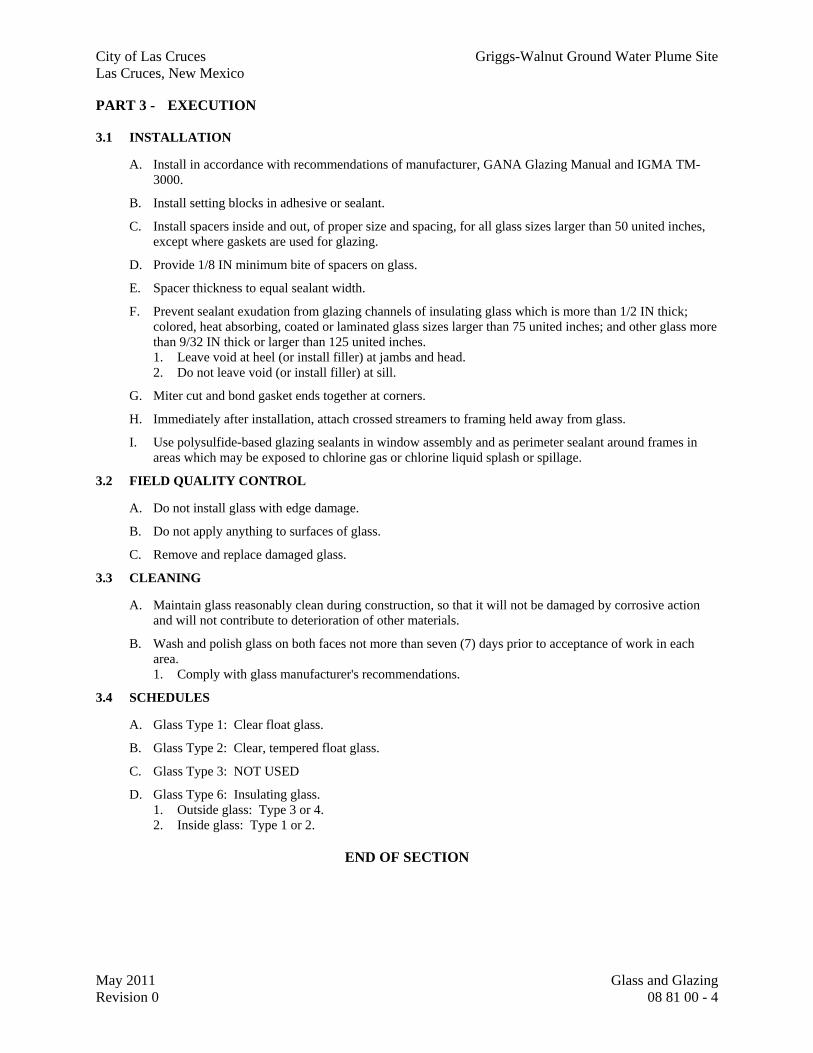
City of Las Cruces Griggs-Walnut Ground Water Plume Site Las Cruces, New Mexico
May 2011 Glass and Glazing Revision 0 08 81 00 - 4
PART 3 - EXECUTION
3.1 INSTALLATION
A. Install in accordance with recommendations of manufacturer, GANA Glazing Manual and IGMA TM-3000.
B. Install setting blocks in adhesive or sealant.
C. Install spacers inside and out, of proper size and spacing, for all glass sizes larger than 50 united inches, except where gaskets are used for glazing.
D. Provide 1/8 IN minimum bite of spacers on glass.
E. Spacer thickness to equal sealant width.
F. Prevent sealant exudation from glazing channels of insulating glass which is more than 1/2 IN thick; colored, heat absorbing, coated or laminated glass sizes larger than 75 united inches; and other glass more than 9/32 IN thick or larger than 125 united inches. 1. Leave void at heel (or install filler) at jambs and head. 2. Do not leave void (or install filler) at sill.
G. Miter cut and bond gasket ends together at corners.
H. Immediately after installation, attach crossed streamers to framing held away from glass.
I. Use polysulfide-based glazing sealants in window assembly and as perimeter sealant around frames in areas which may be exposed to chlorine gas or chlorine liquid splash or spillage.
3.2 FIELD QUALITY CONTROL
A. Do not install glass with edge damage.
B. Do not apply anything to surfaces of glass.
C. Remove and replace damaged glass.
3.3 CLEANING
A. Maintain glass reasonably clean during construction, so that it will not be damaged by corrosive action and will not contribute to deterioration of other materials.
B. Wash and polish glass on both faces not more than seven (7) days prior to acceptance of work in each area. 1. Comply with glass manufacturer's recommendations.
3.4 SCHEDULES
A. Glass Type 1: Clear float glass.
B. Glass Type 2: Clear, tempered float glass.
C. Glass Type 3: NOT USED
D. Glass Type 6: Insulating glass. 1. Outside glass: Type 3 or 4. 2. Inside glass: Type 1 or 2.
END OF SECTION

Division 9

City of Las Cruces Griggs-Walnut Ground Water Plume Site Las Cruces, New Mexico
May 2011 Non-Structural Metal Framing Revision 0 09 22 16 - 1
SECTION 09 22 16
NON-STRUCTURAL METAL FRAMING
PART 1 - GENERAL
1.1 SUMMARY
A. Furnish all labor, materials, tools, equipment, and services for Non-Structural Metal Framing, as indicated, in accordance with provisions of Contract Documents.
B. Completely coordinate with work of other trades.
1.2 QUALITY ASSURANCE
A. General: 1. Where fire resistance classifications are indicated for walls or partitions: Provide studs and
accessories of type tested and listed for construction indicated. 2. Products proposed for use in fire-rated assemblies shall be approved by nationally recognized
testing laboratory.
B. ASTM Reference Standards: 1. ASTM-C645: Standard Specification for Nonstructural Steel Framing Members. 2. ASTM-A653: Standard Specification for Steel Sheet, Zinc-Coated (Galvanized) or Zinc-Iron
Alloy-Coated (Galvannealed) by the Hot-Dip Process. 3. ASTM-C754: Standard Specification for Installation of Steel Framing Members to Receive
Screw-Attached Gypsum Panel Products. 4. ASTM A 1003: Standard Specification for Steel Sheet, Carbon, Metallic- and – Nonmetallic-
Coated for Cold-Formed Framing Members.
C. Select steel studs in accordance with manufacturer's standard load tables and following design pressures and maximum deflections:
PERFORMANCE CRITERIA
Use Condition 2 Design
Pressure Maximum Deflection
Wall enclosing stairs, elevator hoistways, and other vertical shafts
480 Pa 10
LBS/FT2 L/120
Wall enclosing vestibules, ground floor lobbies, and similar spaces subject to intermittent exposure to exterior wind conditions
720 Pa 15
LBS/FT2 L/240
Walls scheduled with Cementitious Backer Board, Moisture-resistant, or Abuse-Resistant Gypsum Wallboard Walls scheduled to receive Tile, lath and plaster, or veneer plaster. 1
240 Pa 5
LBS/FT2 L/360
Typical Interior Walls/Partitions (those not listed above)
240 Pa 5
L/240

City of Las Cruces Griggs-Walnut Ground Water Plume Site Las Cruces, New Mexico
May 2011 Non-Structural Metal Framing Revision 0 09 22 16 - 2
LBS/FT2
Interior Ceilings, Soffits and Bulkheads 240 Pa
5 LBS/FT2
L/360
Footnotes: 1. Limit deflection to L/360 where wall cladding on either face is any of the
following: Ceramic Tile, Stone Tile, Porcelain Tile, Thin Brick, Lath & Plaster, Simulated Masonry, Adhered-stone, Veneer Plaster and similar brittle finishes which are prone to movement-induced cracking.
2. Where elements meet multiple conditions; Use most stringent Deflection and Design Pressure values.
1.3 SUBMITTALS
A. Project Information: 1. Manufacturer of listed products.
PART 2 - PRODUCTS
2.1 ACCEPTABLE MANUFACTURERS
A. Non-structural Metal Framing: 1. Base:
a. Dietrich Industries (Worthington Industries). 2. Optional:
a. ClarkWestern Building Systems. b. California Expanded Metal Products Co. (CEMCO). c. Custom Stud Inc. d. Marino/WARE. e. MRI Steel Framing LLC. f. The Steel Network. g. Telling Industries.
B. Interlocking Grid Support Systems for Gypsum Board Ceilings: 1. Base:
a. USG Corporation. 2. Optional:
a. Armstrong. b. Chicago Metallic.
C. Other manufacturers desiring approval comply with Section 01 60 00.
2.2 MATERIAL DESCRIPTION
A. General: 1. Products proposed for use in fire-rated assemblies shall be approved by nationally recognized
testing laboratory.
B. Metal Studs: 1. C-shaped studs and tracks roll-formed from corrosion-resistant galvanized steel that conforms
to ASTM-C645.

City of Las Cruces Griggs-Walnut Ground Water Plume Site Las Cruces, New Mexico
May 2011 Non-Structural Metal Framing Revision 0 09 22 16 - 3
2. Galvanized: ASTM-A653, Z120 G40. 3. Stud Depths: As indicated by Wall Types. 4. Minimum Flanges Width: 32mm 1-1/4 IN. 5. Minimum thickness: 0.45mm 18 mil (25 GA), except as follows:
a. Provide heavier thickness as required to comply with performance criteria. b. Upgrade framing members to minimum 0.75mm 30 mil (20 GA) studs at following
conditions: 1) At jambs of openings: Two 0.75mm 30 mil (20 GA) studs. 2) One or both sides of partition will be faced with any of following:
a) Wall mounted cabinetry and equipment. b) Tile backing board. c) Adhered stone. d) Plaster. e) Moisture-resistant. f) Abuse-resistant wallboard. g) Lead backed gypsum wallboard.
3) Where partitions are not extended to overhead structural deck, and are without supporting diagonal bracing, or horizontal stiffeners.
c. Provide heavier gauge thickness where specifically indicated. 6. Instead of heavier stud thickness, the design may employ diagonal braces (kickers) above the
ceiling to reduce the overall span and thus stiffen the wall frame. Coordinate locations with building services items. a. Do not employ studs with stud thickness less than allowed by Fire Resistance-rated
assemblies. 7. Base Products:
a. Studs: “Ultrasteel” by Dietrich. b. Tracks (runners): “TR-Series” by Dietrich.
C. Head-of-Wall Accessories: 1. General Criteria:
a. Configure to permit deflection of overhead superstructure while maintaining structural integrity, fire and smoke-resistance, and sound control as required by each wall.
2. Basis of Design - Slotted Top Track (a.k.a. deflection Track): a. Deep leg, vertically slotted track for all walls which extend to structure. b. Minimum Thickness: 30 mil (20 GA). c. Width: As required for studs sizes indicated. d. Depth: Minimum 2-1/2 IN down-standing legs with 1/4 IN wide by 1-1/2 IN high slots
spaced 1 IN on center. e. Material: Cold-formed sheet steel; galvanized; ASTM-A653, Z180, G60. f. Base Product: “SLP-TRK” by Sliptrack Systems, Dietrich, ClarkWestern, etc. g. Accessories:
1) Include fasteners suitable for attachment to superstructure elements. 2) Include Z-bars, cold formed channels, or similar clips to accommodate thickness of
Spay-applied Fire-Resistive Materials (SFRM). h. Additional components where walls are fire-rated:
1) Include fasteners, clips and other items necessary to secure wall frame to building superstructure according to UL-listed designs.
2) Select systems tested in accordance with UL-2079 for conditions. 3. Alternative top track configurations may be considered by Architect for approval.

City of Las Cruces Griggs-Walnut Ground Water Plume Site Las Cruces, New Mexico
May 2011 Non-Structural Metal Framing Revision 0 09 22 16 - 4
a. Proposed systems must be configured to accommodate deflection of superstructure without inducing axial loading on the partition wall.
b. Proposed systems must be tested for fire resistive requirements indicated. c. Contractor is obligated to demonstrate to Architect that proposed system complies with
project requirements.
D. Furring Channels (hat-channels): 1. Hat-shaped sections. 2. Galvanized: ASTM-A653, Z120 G40. 3. Sizes: 7/8 and 1-1/2 IN, as indicated. 4. Minimum Thickness: 30 mil (20 GA); Use heavier gauge as dictated by conditions. 5. Base Product: “FC-Series” by Dietrich.
E. Z-Furring: 1. Z-shaped sections, attached to structural parent wall. 2. Galvanized: ASTM-A653, Z120 G40. 3. Sizes: 1, 1-1/2, 2 and 2-1/2 IN, as indicated. 4. Minimum Thickness: 18 mil (25 GA); Use heavier gauge as dictated by conditions. 5. Base Product: “ZF-Series” by Dietrich.
2.3 ACCESSORY ITEMS
A. Wire ties: 1. 1.09mm 43 mil (18 GA) soft annealed, galvanized.
B. Fasteners for tracks: 1. Power driven type, to withstand minimum 845 N 190 LB shear when driven.
C. Closure: 1. When continuous vapor retarder is required, provide continuous 0.75mm 30 mil (20 GA)
galvanized closure angle to receive vapor retarder and vapor retarder tape.
D. Isolation Strip Material: 1. Non-absorbent, foam padding as required to prevent direct contact between metal framing
member and exterior concrete or masonry walls. 2. Minimum thickness: 1mm 0.40 mil.
E. Backing (modified track runners): 1. C-shaped track runners; roll-formed from corrosion-resistant galvanized steel that conforming
to ASTM-C645. 2. Galvanized: ASTM-A653, Z120 G40. 3. Minimum Backing Height: 150mm 6 IN. 4. Minimum Flange Width: 32mm 1-1/4 IN. 5. Minimum Thickness: 0.75mm 30 mil (20 GA). 6. Base Product: “TR-Series Track Runner” by Dietrich.
2.4 SUPPORT SYSTEMS FOR GYPSUM CEILINGS
A. Interlocking Grid Systems: 1. Description: ASTM-C645, direct-hung system composed of T-Shaped framing members
designed to carry load of screw-applied gypsum ceiling board. 2. Tabs on Cross-Tees to interlock into slots in Main Runners where intersections occur. 3. Base Product: “Drywall Suspension System” by USG Corporation.

City of Las Cruces Griggs-Walnut Ground Water Plume Site Las Cruces, New Mexico
May 2011 Non-Structural Metal Framing Revision 0 09 22 16 - 5
4. Optional Products: “Drywall Grid Systems” by Armstrong; “Drywall Furring System” by Chicago Metallic.
5. Other items including suspension wire, tie wire, attachment devices: As specified and indicated.
B. Track and Channel Systems: 1. Material: ASTM-C645 roll-formed steel with G40 galvanized coating. 2. Minimum Thickness: 0.75mm 30 mil (20 GA); Use heavier gauge as dictated by conditions. 3. Carrying Channels:
a. Size: 38mm 1-1/2 IN. 4. Furring Channels (hat-channels):
a. Sizes: 22 and 38mm 7/8 and 1-1/2 IN, as indicated. 5. Other items including suspension wire, tie wire, attachment devices: As specified and
indicated.
C. Stud-Framed Ceiling/Soffit Systems: 1. C-shaped studs or joists; roll-formed from corrosion-resistant galvanized steel that conforms to
ASTM-C645. 2. Galvanized Coating: ASTM-A653, Z120 G40. 3. Minimum Frame Member Depth: 3-5/8 IN minimum, unless otherwise indicated.
a. Use wider stud sections if ceiling span and support requires. 4. Minimum flange width: 32mm 1-1/4 IN. 5. Minimum stud thickness: 20 gauge. 6. Other items including suspension wire, tie wire, attachment devices: As specified and
indicated.
D. Tie Wire: 1. Material: ASTM-A641, Class 1 zinc coating, soft temper. 2. Minimum Diameter (single-strand): 1.6mm 0.0625 IN (14 GA). 3. Minimum Diameter (double-strand): 1.2mm 0.0475 IN (18 GA).
E. Wire Hangers: 1. Material: ASTM-A641, Class 1 zinc coating, soft temper. 2. Minimum Diameter: 4.12mm 0.162 IN (8 GA).
F. Anchors in Concrete: 1. Anchors of type and material indicated below, with holes or loops for attaching hangers of type
indicated and with capability to sustain, without failure, a load equal to 5 times that imposed by ceiling construction, as determined by testing per ASTM-E488 or ASTM-E1512 as applicable.
2. Acceptable types: Cast-in-place, post-installed expansion anchors and post-installed bonded anchors.
3. Material: Carbon-steel components zinc plated to comply with ASTM-B633, Class Fe/Zn 5 (0.005 mm) for Class SC 1 service condition.
G. Power-Actuated Fasteners in Concrete: 1. Fastener system of type suitable for application indicated, fabricated from corrosion-resistant
materials, with clips or other accessory devices for attaching hangers of type indicated, and with capability to sustain, without failure, a load equal to 10 times that imposed by ceiling construction, as determined by testing per ASTM-E1190.
2. Comply with seismic design requirements where applicable.

City of Las Cruces Griggs-Walnut Ground Water Plume Site Las Cruces, New Mexico
May 2011 Non-Structural Metal Framing Revision 0 09 22 16 - 6
PART 3 - EXECUTION
3.1 INSPECTION
A. Examine supporting structure and conditions under which system will be installed.
B. Correct conditions detrimental to proper installation.
C. Installation constitutes acceptance of responsibility for performance.
3.2 INSTALLATION - GENERAL
A. General: 1. Layout and install metal framing accurate to dimensions indicated in drawings. 2. Installation Standard: ASTM-C754, except comply with framing sizes and spacing indicated.
a. Gypsum Board Assemblies: Comply with additional requirements in ASTM-C840 relative to framing installation.
3. Install supplementary framing, and blocking to support fixtures, equipment services, heavy trim, grab bars, toilet accessories, furnishings, or similar construction.
4. Install bracing at terminations in assemblies. 5. Do not bridge building control and expansion joints with non-load-bearing steel framing
members. Frame both sides of joints independently. 6. Where studs are installed directly against exterior masonry walls or dissimilar metals at
exterior walls, install isolation strip between studs and exterior wall. 7. Extend framing full height to structural supports. Exception: Where partitions are indicated to
terminate at, or just above, suspended ceilings. a. Continue framing around ducts and similar items which penetrate partitions.
8. Utilize slip-type head track assemblies where framing extends to overhead structural supports. a. Configure to resist lateral loads while accommodating deflection of overhead building
superstructure without inducing axial loading on partition framing.
B. Size floor tracks and head track assemblies to match studs. 1. Align floor track and deflection track accurately. 2. Secure floor track and deflection track to structure in accordance with manufacturer's
instructions and referenced regulatory requirements. 3. Secure at corners and at ends.
C. Position studs vertically engaging floor track and head-of-wall deflection track. 1. Space studs maximum 405mm 16 IN on center.
a. Provide additional studs at corners, partition intersections and terminations of partitions, and at each side of control joints.
b. Positively anchor studs to floor tracks with self-tapping pan head screws, or stud clinching tool on both flanges of each stud.
c. Positively anchor studs to deflection track with wafer-head screws on both flanges of each stud.
D. Fire rated partitions: Anchor as required by fire resistance design, and Firestopping design.
E. Align stud knockouts to facilitate running of wires and conduit.
F. Where partitions abut vertical structural elements, provide perimeter relief. 1. Gypsum Association GA-600, Figure 9.
G. Head-of-Wall: 1. Provide slotted top track for all walls that go to structure.

City of Las Cruces Griggs-Walnut Ground Water Plume Site Las Cruces, New Mexico
May 2011 Non-Structural Metal Framing Revision 0 09 22 16 - 7
2. Secure top track to superstructure with 3.7mm x 25mm 0.145 IN x 1 IN powder actuated fasteners located 400mm 16 IN on center (max). a. Pre-fit forming material that may be required as a part of a fire-resistive joint system.
3. Where partitions attach to structural elements that are scheduled to receive Spray-applied Fire Resistive Materials (SFRM): a. Install Z-bar to underside of steel beams and steel deck before sprayed fireproofing is
applied. b. Locate Z-bars perpendicular to line of partition, spaced maximum 400mm 16 IN on center. c. Attach each Z-bar with two 3.7mm x 25mm 0.145 IN x 1 IN powder-actuated fasteners
located minimum 25mm 1 IN from ends of Z-bar. d. After fireproofing, secure top track to Z-bars with 4 mm x 17 mm No. 8 x 5/8 IN
waferhead framing screws spaced maximum 400mm 16 IN on center. 4. Where fire-rated partitions are offset and will not clear fireproofed steel beam, extend Z-bar
outrigger horizontally from bottom of beam out to minimum 50mm 2 IN beyond width of head-of-wall. a. Attach 19mm 3/4 IN expanded metal lath continuous, width of top of Z-bar outriggers
prior to fireproofing steel beam to accommodate sprayed fireproofing. 5. Cut vertical studs 16mm 5/8 IN short to create a deflection gap when installed into top track.
a. Secure vertical studs to top track with No. 8 x 9/16 IN waferhead framing screw at each stud flange, screwing through track slots for positive stud connection.
6. Secure Gypsum Wallboard to vertical studs; do not secure Gypsum Wallboard to top track directly.
7. Prepare wall for installation of seals, firestopping, or both: a. Non-fire rated partitions (including Smoke Partitions): Prepare for Acoustical Sealant
specified in Section 09 29 00.
H. Furring Channels: 1. Install furring channel systems, directly attached to parent walls, as indicated. 2. Install channels at maximum 405mm 16 IN OC. 3. Provide additional framing at openings, cutouts, corners, and control joints. 4. Fasten to masonry walls with cut nails. 5. Fasten to concrete with power driven fasteners. 6. Space fasteners not more than 610mm 24 IN OC, staggered on opposite flanges of hat
channels.
3.3 FRAMING AT OPENINGS
A. General: 1. Control Joints (CJ): Provide for control joints at all openings.
a. Install additional stud, maximum 13mm 1/2 IN from jamb studs. b. Do not fasten extra stud to track or jamb stud. c. Refer to specification Section 09 29 00 for control joint locations.
2. Prefabricated headers, jambs, and sill framing systems (optional): a. Proprietary opening framing systems may be considered as an alternative to conventionally
fabricated framing. b. Pre-approved Products: “HDS Framing System” by Dietrich. c. Submit proposed alternative systems to Architect for review.
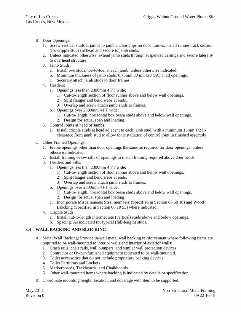
City of Las Cruces Griggs-Walnut Ground Water Plume Site Las Cruces, New Mexico
May 2011 Non-Structural Metal Framing Revision 0 09 22 16 - 8
B. Door Openings: 1. Screw vertical studs at jambs to jamb anchor clips on door frames; install runner track section
(for cripple studs) at head and secure to jamb studs. 2. Unless indicated otherwise, extend jamb studs through suspended ceilings and secure laterally
to overhead structure. 3. Jamb Studs:
a. Install two studs, toe-to-toe, at each jamb, unless otherwise indicated. b. Minimum thickness of jamb studs: 0.75mm 30 mil (20 GA) at all openings. c. Securely attach jamb studs to door frames.
4. Headers: a. Openings less than 2300mm 4 FT wide:
1) Cut-to-length section of floor runner above and below wall openings. 2) Split flanges and bend webs at ends. 3) Overlap and screw attach jamb studs to frames.
b. Openings over 2300mm 4 FT wide: 1) Cut-to-length, horizontal box beam studs above and below wall openings. 2) Design for actual span and loading.
5. Control Joints at head of Jambs: a. Install cripple studs at head adjacent to each jamb stud, with a minimum 13mm 1/2 IN
clearance from jamb stud to allow for installation of control joint in finished assembly.
C. Other Framed Openings: 1. Frame openings other than door openings the same as required for door openings, unless
otherwise indicated. 2. Install framing below sills of openings to match framing required above door heads. 3. Headers and Sills:
a. Openings less than 2300mm 4 FT wide: 1) Cut-to-length section of floor runner above and below wall openings. 2) Split flanges and bend webs at ends. 3) Overlap and screw attach jamb studs to frames.
b. Openings over 2300mm 4 FT wide: 1) Cut-to-length, horizontal box beam studs above and below wall openings. 2) Design for actual span and loading.
c. Incorporate Miscellaneous Steel members (Specified in Section 05 50 10) and Wood Blocking (Specified in Section 06 10 53) where indicated.
4. Cripple Studs: a. Install cut-to-length intermediate (vertical) studs above and below openings. b. Spacing: As indicated for typical (full-length) studs.
3.4 WALL BACKING AND BLOCKING
A. Metal Wall Backing: Provide in-wall metal wall backing reinforcement where following items are required to be wall-mounted to interior walls and interior of exterior walls: 1. Crash rails, chair rails, wall bumpers, and similar wall protection devices. 2. Contractor or Owner-furnished equipment indicated to be wall-mounted. 3. Toilet accessories that do not include proprietary backing devices. 4. Toilet Partitions and Lockers. 5. Markerboards, Tackboards, and Chalkboards. 6. Other wall-mounted items where backing is indicated by details or specification.
B. Coordinate mounting height, location, and coverage with item to be supported.

City of Las Cruces Griggs-Walnut Ground Water Plume Site Las Cruces, New Mexico
May 2011 Non-Structural Metal Framing Revision 0 09 22 16 - 9
C. Determine material width according to item to be supported.
D. Provide in-wall metal wall backing material to interior metal stud walls specified herein and “Exterior” stud walls
E. Attachment: Minimum 2 - #10 sheet metal screws at each stud.
3.5 INSTALLATION - CEILING
A. Install in compliance with manufacturer's recommendations.
B. Provide required items to support and trim out neatly, flush or recessed mechanical and electrical items.
C. Frame openings in ceiling support system to accommodate access panels and similar openings and penetrations. 1. Completely frame openings with closed channel side of stud facing opening for support of
recessed mechanical and electrical items.
3.6 INSTALLING CEILING SUPPORT SYSTEMS
A. Install suspension system components in sizes and spacings indicated on Drawings, but not less than those required by referenced installation standards for assembly types and other assembly components indicated.
B. Isolate suspension systems from building structure where they abut or are penetrated by building structure to prevent transfer of loading imposed by structural movement.
C. Suspend hangers from building structure as follows: 1. Install hangers plumb and free from contact with insulation or other objects within ceiling
plenum that are not part of supporting structural or suspension system. a. Splay hangers only where required to miss obstructions and offset resulting horizontal
forces by bracing, countersplaying, or other equally effective means. 2. Where width of ducts and other construction within ceiling plenum produces hanger spacings
that interfere with locations of hangers required to support standard suspension system members, install supplemental suspension members and hangers in the form of trapezes or equivalent devices. a. Size supplemental suspension members and hangers to support ceiling loads within
performance limits established by referenced installation standards. 3. Wire Hangers: Secure by looping and wire tying, either directly to structures or to inserts, eye
screws, or other devices and fasteners that are secure and appropriate for substrate, and in a manner that will not cause hangers to deteriorate or otherwise fail.
4. Flat Hangers: Secure to structure, including intermediate framing members, by attaching to inserts, eye screws, or other devices and fasteners that are secure and appropriate for structure and hanger, and in a manner that will not cause hangers to deteriorate or otherwise fail.
5. Do not attach hangers to steel roof deck. 6. Do not attach hangers to permanent metal forms. Furnish cast-in-place hanger inserts that
extend through forms. 7. Do not attach hangers to rolled-in hanger tabs of composite steel floor deck. 8. Do not connect or suspend steel framing from ducts, pipes, or conduit.

City of Las Cruces Griggs-Walnut Ground Water Plume Site Las Cruces, New Mexico
May 2011 Non-Structural Metal Framing Revision 0 09 22 16 - 10
D. Grid Suspension Systems: 1. Attach perimeter wall track or angle where grid suspension systems meet vertical surfaces. 2. Mechanically join main beam and cross-furring members to each other and butt-cut to fit into
wall track.
E. Installation Tolerances: 1. Install suspension systems that are level to within 3mm in 3.6 m 1/8 IN in 12 FT measured
lengthwise on each member that will receive finishes and transversely between parallel members that will receive finishes.
END OF SECTION

City of Las Cruces Griggs-Walnut Ground Water Plume Site Las Cruces, New Mexico
May 2011 Gypsum Board Revision 0 09 29 00 - 1
SECTION 09 29 00
GYPSUM BOARD
PART 1 - GENERAL
1.1 SUMMARY
A. Section Includes: 1. Gypsum board work.
B. Related Specification Sections include but are not necessarily limited to: 1. Division 00 - Bidding Requirements, Contract Forms, and Conditions of the Contract. 2. Division 01 - General Requirements. 3. Section 09 22 16 - Non-Load-Bearing Wall Framing Systems.
1.2 QUALITY ASSURANCE
A. Referenced Standards: 1. American National Standards Institute (ANSI):
a. A108.11, Specification for Interior Installations of Cementitious Backer Units. 2. ASTM International (ASTM):
a. A653, Standard Specification for Steel Sheet, Zinc-Coated (Galvanized) or Zinc-Iron Alloy-Coated (Galvannealed) by the Hot-Dip Process.
b. C475, Standard Specification for Joint Compound and Joint Tape for Finishing Gypsum Board. c. C840, Standard Specification for Application and Finishing of Gypsum Board. d. C1396, Standard Specification for Gypsum Board.
3. Gypsum Association (GA): a. GA-214, Recommended Levels of Gypsum Board Finish.
4. Underwriters Laboratories, Inc. (UL): a. Building Materials Directory. b. Fire Resistance Directory.
1.3 DEFINITIONS
A. Wet Area: Toilets, showers, laboratories, janitor closets (or areas around janitor sink), and areas around emergency eye wash/showers.
1.4 SUBMITTALS
A. Shop Drawings: 1. See Specification Section 01 33 00 for requirements for the mechanics and administration of the
submittal process. 2. Drawings of unusual conditions.
a. Control joint layout. 3. Product technical data including:
a. Acknowledgement that products submitted meet requirements of standards referenced. b. Manufacturer's installation instructions.
4. Manufacturer's adhesive, sealer, joint treatment compound and tape recommendations.
PART 2 - PRODUCTS
2.1 ACCEPTABLE MANUFACTURERS
A. Subject to compliance with the Contract Documents, the following manufacturers are acceptable:

City of Las Cruces Griggs-Walnut Ground Water Plume Site Las Cruces, New Mexico
May 2011 Gypsum Board Revision 0 09 29 00 - 2
1. Gypsum board and accessories: a. Georgia - Pacific. b. National Gypsum. c. U.S. Gypsum Co.
2. Cement board and accessories: a. U.S. Gypsum Co. b. National Gypsum.
3. Gypsum board suspension system: a. Chicago Metallic Corp.
B. Submit request for substitution in accordance with Specification Section 01 60 00.
2.2 MATERIALS
A. Gypsum Board (GB): 1. ASTM C1396. 2. Furnish in lengths as long as practicable with tapered edges. 3. Regular board: 5/8 IN thick. 4. Radius Construction: 1/4 IN thick.
B. Adhesive: As recommended by board manufacturer.
C. Sealers for Water Resistant Board: Recommended by board manufacturer.
D. Joint Treatment Compound: 1. ASTM C475. 2. Recommended by manufacturer for specified board type and location. 3. Do not use self-adhesive fiber mesh tape.
E. Joint Tape: 1. ASTM C475. 2. Recommended by manufacturer for specified board type and location.
2.3 ACCESSORIES
A. General: 1. ASTM A653, galvanized G90.
B. Corner Bead: 1. Standard type with perforated flanges.
C. Casing and Trim Bead: Manufacturer's standard product.
D. Control and Expansion Joints: Manufacturer's standard product.
E. Fasteners: 1. Gypsum board:
a. Self-drilling Type S, corrosion-resistant bugle head screws. b. Provide stainless steel fasteners in wet areas.
2. Cement backer board: a. Self-drilling, corrosion resistant wafer head screws with strip-out prevention ribs. b. Do not use drywall screws.
F. Foam Tape: PVC, 1/2 IN x 1/4 IN pressure sensitive.
G. Tie Wire and Suspension Wire: 1. Galvanized, soft annealed 12 GA minimum. 2. Use soft stainless steel wire of same gage in all wet areas and/or exterior areas.
H. Gypsum Board Suspension System: 1. Direct hung factory fabricated heavy duty rated, single web system. 2. Electro-galvanized. 3. Fire rated system, UL listed.

City of Las Cruces Griggs-Walnut Ground Water Plume Site Las Cruces, New Mexico
May 2011 Gypsum Board Revision 0 09 29 00 - 3
4. Chicago Metallic "Fire Front 650 Drywall Furring System."
PART 3 - EXECUTION
3.1 INSTALLATION
A. General: 1. Install board in fire-rated walls in accordance with UL requirements.
a. Self-adhesive applied fire rated tape is not acceptable for use on board joints in fire rated walls. b. Tape all joints using conventional fire rated joint tape and joint treatment compound.
2. Erect all board vertically with edges over supporting members. a. See Specification Section 09 22 16 for non-loading bearing metal studs.
3. Secure to each support or framing member with screws. 4. In areas having gypsum board ceilings and walls, install ceiling first. 5. Bring boards into contact, but do not force into place. 6. Fit neatly and carefully. 7. Stagger edge joints on opposite side of a partition so they occur on different framing members. 8. Hold board in firm contact with support while fasteners are being driven. 9. Proceed with attachment from center of board toward ends and edges. 10. Scribe board prior to cutting. 11. Seal ends, cutouts and screw penetrations with W/R sealant where type WR board is used.
B. Application: 1. Gypsum board:
a. Use 5/8 IN thick board for general and fire-rated construction. b. Use non-rated gypsum board unless noted otherwise.
2. Gypsum board for use in ceilings: a. Dry area ceilings: Provide 5/8 IN thick fire-rated board best suited and recommended by
manufacturer for intended use. b. Wet area ceilings (showers and other areas where ceilings will be exposed to direct water contact
or condensation): Provide 5/8 IN thick fire-rated board approved by manufacturer for use in high humidity areas.
c. Where ceilings abutt a concrete or masonry wall provide 3/8 IN joint between edge of wall and ceiling board. 1) Provide continuous solid casing bead trim on edge of board. 2) Seal joint with sealant and backer rod.
3. Gypsum liner panel: a. Use WR boards in walls common to wet areas.
4. Casing and trim bead: a. Where bead abuts exterior window or other metal components, separate from other material
using foam tape. 5. Fasteners:
a. Provide fasteners of sufficient length to penetrate framing member or stud not less than 3/8 IN. 6. In curved wall or ceiling applications use 1/4 IN thick board specifically designed for use in radius
construction. a. Apply in multiple layers as required to meet minimum drywall thickness specified.
C. Installation (Single-Layer System): 1. Set fasteners between 3/8 and 1/2 IN from edges and 2 IN in from board corner.
a. Space maximum of 12 IN on center at edges and in field of board. b. Where board butts at wall/ceiling juncture, hold fasteners back 6 IN from edges. c. Space fasteners closer if required by UL.
2. Install fasteners, in gypsum board, so that head rests in a slight dimple without cutting face paper or fracturing core or as recommended by board/panel manufacturer.
3. Install screws, in cement backer board, flush with board surface. a. Do not countersink screws.

City of Las Cruces Griggs-Walnut Ground Water Plume Site Las Cruces, New Mexico
May 2011 Gypsum Board Revision 0 09 29 00 - 4
D. Control Joints: 1. Install prefabricated control joints to provide following maximum unjointed lengths or areas:
a. Control joints: #093 zinc coated control joint. b. Partitions: 30 FT, maximum straight run, and at lock side of jamb from head of each door
opening to top of partition. c. Ceilings: 50 FT maximum in one (1) direction, and at change of direction or irregular shapes. d. Ceiling area: 2500 SF, maximum.
2. Calk control joints. a. Use color to match wall or ceiling color as closely as possible.
3. Where control or expansion joints occur in fire or sound rated assemblies, install suitable backing material to maintain required rating.
4. Where a partition or ceiling abuts a structural element or dissimilar wall or ceiling, install corner bead, casing bead or other trim as required.
E. Board Finishing: 1. Securely attach continuous corner beads to all external corners in accordance with manufacturer's
recommendations. 2. Provide the following minimum levels of gypsum board finish in accordance with GA-214.
a. Areas exposed to view: 1) Surfaces to receive vinyl wall covering: Level #4. 2) Surfaces to receive painted finish: Level #5.
b. Areas not exposed to view: 1) Fire rated partitions: Level #2 unless a higher grade of finish is required by UL. 2) Non-fire rated partitions: Level #2.
c. Provide additional coats of joint compound as required to completely conceal joints, fasteners and accessories. 1) Joint photographing will not be acceptable.
3. Sand each coat to remove excess joint compound. a. Avoid roughing paper facing on board.
4. Finish surface shall be smooth and free of tool marks and ridges. 5. After primer has been applied to wall surface, repair and refinish all areas which show defects. 6. Refer to ASTM C840 for additional finishing requirements.
F. Install ceiling suspension system in accordance with manufacturer's recommendations.
END OF SECTION

City of Las Cruces Griggs-Walnut Ground Water Plume Site Las Cruces, New Mexico
May 2011 Acoustical and Ceiling Tile Materials Revision 0 09 51 00 - 1
SECTION 09 51 00
ACOUSTICAL AND CEILING TILE MATERIALS (AM)
PART 1 - GENERAL
1.1 SUMMARY
A. Furnish all labor, materials, tools, equipment, and services for Acoustical & Ceiling Tile Materials (AM), as indicated, in accordance with provisions of Contract Documents.
B. Completely coordinate with work of other trades.
1.2 QUALITY ASSURANCE
A. Standard for suspension systems: ASTM-C635
B. Standard for installation: ASTM-C636.
C. Site Classification and Design Categories as defined in the International Building Code.
D. Ceilings and Interior Systems Construction Association (CISCA). 1. Seismic Zones 0 through 2.
E. Suspension System Design Parameters: 1. Comply with:
a. Currently enforced International Building Code with state amendments, local amendments, or both.
b. CISCA Standards: Current latest edition unless other editions are referenced by above building code and ASCE-7.
c. International Code Council-Evaluation Services ICCES – ESR-1308 Fire and Nonfire-Resistance Rate Suspended Ceiling Framing Systems.
2. See Structural Drawings for Seismic Category.
1.3 SUBMITTALS
A. Samples: 1. Three samples of each material selected for verification.
B. Contract Closeout Information: 1. Maintenance data. 2. Letter stating extra material has been delivered. 3. Interior finish fire performance data:
a. Provide for each finish material and type specified: 1) Manufacturer's printed information including:
a) Fire class. b) NFPA test number. c) Photograph.
2) Proof of purchase.

City of Las Cruces Griggs-Walnut Ground Water Plume Site Las Cruces, New Mexico
May 2011 Acoustical and Ceiling Tile Materials Revision 0 09 51 00 - 2
PART 2 - PRODUCTS
2.1 ACCEPTABLE MANUFACTURERS
A. Steel Suspension Systems: 1. Base:
a. As noted for individual types in Room Finish and Color Schedule,
B. Other manufacturers desiring approval comply with Section 01 60 00.
2.2 MATERIALS - ACOUSTICAL SUSPENSION SYSTEMS
A. Suspension systems - General: 1. Heavy duty systems, ASTM-C635. 2. Main runner jointing by spliced, interlocking ends, tab locks, pin locks, or other suitable
connections. 3. Cross runners interlocking with main runners. 4. Provide types indicated.
B. Hanger Wire: 1. General:
a. Pre-stretched, with a yield stress load of at least 5 times design load, but not less than 2.05mm 0.080 IN (12 GA).
b. Utilize continuous lengths, without kinks and splices. 2. Galvanized Steel, general use:
a. Galvanized, soft annealed steel wire conforming to ASTM-A641.
C. Provide moldings wherever ceiling meets walls, partitions, other vertical elements, and other types of ceilings or ceiling fixtures. No additional trim is required at ceiling mounted fixtures with integral flange trim.
D. Attachment Devices: 1. Size for 5 times the design load indicated in ASTM-C635, Table 1, Direct Hung, unless
otherwise indicated. a. Comply with International Building Code and Seismic Category as defined in the
Structural Drawings. 2. Anchors in Concrete:
a. Anchors of type and material indicated below, with holes or loops for attaching hangers of type indicated and with capability to sustain, without failure, a load equal to 5 times that imposed by ceiling construction, as determined by testing per ASTM-E488 or ASTM-E1512 as applicable.
b. Acceptable types: Cast-in-place, post-installed expansion anchors and post-installed bonded anchors.
c. Material: Carbon-steel components zinc plated to comply with ASTM-B633, Class Fe/Zn 5 (0.005 mm) for Class SC 1 service condition.
3. Power-Actuated Fasteners in Concrete: a. Fastener system of type suitable for application indicated, fabricated from corrosion-
resistant materials, with clips or other accessory devices for attaching hangers of type indicated, and with capability to sustain, without failure, a load equal to 10 times that imposed by ceiling construction, as determined by testing per ASTM-E1190.
E. Suspension systems - types: 1. CG-1: Exposed grid, non-rated:

City of Las Cruces Griggs-Walnut Ground Water Plume Site Las Cruces, New Mexico
May 2011 Acoustical and Ceiling Tile Materials Revision 0 09 51 00 - 3
a. Description: Galvanized, double web steel, main and cross runners. b. Face width: 23.8mm 15/16 IN. c. Base Product:
1) Prelude XL, by Armstrong d. Finish on exposed surfaces: Smooth, flat white.
2. CG-15: 24mm 15/16 IN Gasketed Grid; Non-rated: a. Base Product:
1) 15/16 IN Co-Extruded Clean Room Grid System by Armstrong World Industries. b. Optional Product:
1) BarrierGrid Standard 15/16 Exposed Gasketed by Chicago Metallic Corporation. c. Structural Classification of System: ASTM-C635 Intermediate Duty. d. Face Width: 24mm 15/16 IN. e. Height Width: 38mm 1-1/2 IN. f. Provide main and cross tees, gasketed perimeter channels or angles, connectors, splice
connectors and hold down clips for a complete installation. g. Gasket:
1) Factory-applied. 2) Fungus resistance test method 508.1 mill-std 810C. 3) Flame resistance test FMYSS 302 with burn rate of 100mm 4 IN per minute. 4) USDA approval standards.
F. Framing and suspension systems for Gypsum Board Ceilings: 1. Specified in Section 09 22 16.
2.3 MATERIALS - CEILING TILES
A. Acceptable manufacturers (Ceiling Tiles): 1. Ceiling tile - Wet formed mineral fiber:
a. Base: 1) As noted for individual types in Room Finish and Color Schedule, Section 09 06 10.
b. Other manufacturers desiring approval comply with Section 01 60 00. c. General performance description:
1) Scheduled finishes to be factory applied. 2) Light reflectance: Not less than 0.75. 3) Noise reduction coefficient: 0.50 - 0.65. 4) Class A incombustible units. 5) Fire rated units (when used): UL labeled. 6) Edges uniformly fabricated, true, square. 7) Sizes as required to fit scheduled suspension system. 8) Lay-in style: Minimum 16mm 5/8 IN thick. 9) Concealed spline style: Edges kerfed for splines. 10) Standard tile size(s): See Reflected Ceiling Plan(s). 11) Aluminum facing, if scheduled, to be 0.25mm 0.010 IN thick minimum aluminum
sheet with white baked enamel or vinyl coating. 12) Foil facing, if scheduled, to be enhanced aluminum foil with white vinyl coating.
2. Ceiling tile - Gypsum: a. General description/performance:
2.4 EXTRA MATERIAL
A. Provide Owner with one carton of each type and pattern of material for maintenance purposes.

City of Las Cruces Griggs-Walnut Ground Water Plume Site Las Cruces, New Mexico
May 2011 Acoustical and Ceiling Tile Materials Revision 0 09 51 00 - 4
B. Provide in sealed labeled boxes to facilitate identification.
2.5 RELATED MATERIALS (SPECIFIED ELSEWHERE)
A. Diffusers and grilles: Specified in Section 23 31 00.
B. Light Fixtures: Specified in Section 26 51 00.
2.6 FABRICATION
A. Intersections between Main Tees and Cross Tees: Butt cut and notch as required.
B. Perimeter Wall Angles: Fabricate to match the system specified.
C. Include components and accessories necessary resist seismic loads and dead loads of items such as light fixtures and air diffusers.
PART 3 - EXECUTION
3.1 INSPECTION
A. Verify suitability of substrate to accept installation.
B. Examine installation site for unevenness or irregularities that would affect quality and execution of work.
C. Installation constitutes acceptance of responsibility for performance.
3.2 PREPARATION
A. Consult other trades involved before start of ceiling work, to determine areas of potential interference.
B. Coordinate ceiling layout with work penetrating acoustical ceiling systems.
C. Specifically coordinate with sprinkler head spacing.
D. Do not start installation until interferences have been resolved.
3.3 INSTALLATION TOLERANCES
A. Comply with ASTM-C635.
B. Maximum deviation from level plane: Not to exceed 3mm in 3 M 1/8 IN in 10 FT with no load applied.
C. Maximum Bow: Not to exceed 1.3mm in 1 600mm 1/32 IN in 2 FT.
D. Maximum Camber: Not to exceed 1.3mm in 600mm 1/32 IN in 2 FT.
E. Maximum Twist: Not to exceed 1 Degree in 600mm 1 Degree in 2 FT.
3.4 INSTALLATION - SUSPENSION SYSTEM - GENERAL
A. Design and install ceiling system per CISCA standards indicated in Part 1.
B. Install suspension system in accordance with ASTM-C636 and manufacturers' instructions.
C. Grid layout: See Reflected Ceiling Plans.

City of Las Cruces Griggs-Walnut Ground Water Plume Site Las Cruces, New Mexico
May 2011 Acoustical and Ceiling Tile Materials Revision 0 09 51 00 - 5
1. Install grid square with room and with grid center lines or acoustical panel center lines coinciding with center lines of room, each direction. a. Acoustical panel dimension at perimeter walls: Not less than 150mm 6 IN. b. In case of conflict with lighting plan contact Architect.
D. Do not use defective or damaged materials.
E. Leave suspension system ready to accept installation of acoustic materials.
3.5 INSTALLATION – WALL ANGLES
A. Install wall angles where ceilings meet walls, partitions, other vertical elements, and other types of ceilings. 1. Secure wall angles to wall construction at stud locations.
a. Maximum spacing from terminal ends: 75mm 3 IN. b. Draw fasteners tight against vertical surfaces.
2. Level tolerance not more than 1 in 1000. 3. Miter cut inside and outside corners. 4. Install with leg supporting bottom flange of runners.
3.6 INSTALLATION – HANGER WIRES
A. General: 1. Provide hangers and inserts necessary to support ceiling suspension systems and ceiling dead
loads. 2. Locate and align hangers and inserts correctly. 3. Coordinate location and alignment with work of other trades. 4. Do not suspend any part of suspension system from ducts, pipes, conduit, equipment, cable
tray, etc. 5. Provide supplementary rough suspension system where necessary to support ceilings beneath
pipes, ducts, equipment, etc. 6. Install hanger wires plumb to main tees and cross tees. 7. Splay hangers no greater than 30 degrees from vertical to avoid obstructions or other
conditions that prevent plumb, vertical installation. 8. Install wires vertically in such a manner that they are not more than 1:6 out-of-plumb, unless
counter-sloping wires are provided. 9. Do not attach wires to, bent around, interfering material or equipment.
B. Space hangers to prevent loads from items in or on ceiling from causing eccentric deflection and rotation. 1. Provide additional hangers to support lighting fixtures. 2. Provide additional hangers within 150mm 6 IN of end of main runners. 3. Do not bear runners on walls or partitions.
3.7 INSTALLATION – MAIN RUNNERS
A. Utilize wall angles to align and receive terminal ends of main tees without transferring load to Wall Angle.
B. Space main tees as indicated, and as required to receive lay-in panels and fixtures.
C. Support terminal ends of main tees by wires located within 150mm 6 IN from boundary walls.
D. Suspend main tees from building superstructure with hanger wires specified.

City of Las Cruces Griggs-Walnut Ground Water Plume Site Las Cruces, New Mexico
May 2011 Acoustical and Ceiling Tile Materials Revision 0 09 51 00 - 6
E. Support main tees with hanger wire at intervals necessary to support applied load and to satisfy deflection criteria.
3.8 INSTALLATION – CROSS RUNNERS
A. Space cross tees as indicated, and as required to receive lay-in panels and fixtures. 1. Install cross runners with a positive interlock.
B. Utilize wall angles to align and receive terminal ends of Cross Tees without transferring load to Wall Angle.
C. Support terminal ends of cross tees by wires located within 150mm 6 IN from boundary walls.
D. Suspend main tees from building superstructure with hanger wires specified.
E. Support main tees with hanger wire at intervals necessary to support applied load and to satisfy deflection criteria.
3.9 INSTALLATION – LAY-IN ITEMS
A. Install acoustic materials into suspension system in accordance with manufacturer's instructions.
B. Install lay-in panels, fixtures, diffusers, grilles, and similar items in a manner that will not compromise performance of the suspension system. 1. Provide supplemental hangers for fixtures which exceed manufacturer’s published load data.
a. Supplemental hanger systems shall be approved by Building Official.
C. Field cut as required to fit materials to grid. 1. Tegular and similar tiles articulated edges:
a. Field-cut edges to match profile of factory edges and paint to match. b. Ceiling Touch-Up Paint: Armstrong, Global White, latex paint.
1) Use to hide minor surface scratches and nicks and cover field cut edges exposed to view.
D. Make cuts square and true.
E. Do not install damaged units.
F. Install access splines in concealed systems as directed and as required to provide access to concealed items.
G. Identify access tile with a white headed thumb tack.
H. Do not provide access splines for tiles in security areas.
I. Hold-down Clips: 1. Provide Hold-down-clips where Clean Room Class 100 or Clean Room Class 5 tiles are
scheduled. 2. Provide hold down clips if UL rated ceiling requires.
3.10 CLEANING
A. Perform cleaning and replacement of defective units in time to avoid delay in progress of work and before final completion of work.
B. Carefully clean soiled surfaces.
C. Remove and replace irregular, discolored, defective or damaged components at no additional expense to Owner.

City of Las Cruces Griggs-Walnut Ground Water Plume Site Las Cruces, New Mexico
May 2011 Acoustical and Ceiling Tile Materials Revision 0 09 51 00 - 7
3.11 PROTECTION
A. Protect installed materials from damage.
END OF SECTION

City of Las Cruces Griggs-Walnut Ground Water Plume Site Las Cruces, New Mexico
May 2011 Concrete Floor Sealer Revision 0 09 67 81 - 1
SECTION 09 67 81
CONCRETE FLOOR SEALER (CFS-ND)
PART 1 - GENERAL
1.1 SUMMARY
A. Furnish all labor, materials, tools, equipment, and services for Concrete Floor Sealer (CFS-ND), as indicated, in accordance with provisions of the Contract Documents.
B. Completely coordinate with work of other trades.
1.2 REFERENCES
A. American Society for Testing and Materials: 1. ASTM C1315 - Standard Specification for Liquid Membrane-Forming Compounds Having
Special Properties for Curing and Sealing Concrete
1.3 QUALITY ASSURANCE
A. Applicator must be a licensee of manufacturer, or approved in writing.
1.4 SUBMITTALS
A. Project Information: 1. Maintenance data. 2. Warranty.
1.5 JOB CONDITIONS
A. Install only when surface and ambient temperatures are between 45 and 85 deg F (6 and 29 deg C).
B. Install prior to other finishes.
C. Provide adequate ventilation during installation.
D. Take proper precautions for use of flammable materials.
1.6 WARRANTY
A. Written warranty signed jointly by applicator and manufacturer.
B. Manufacturer’s standard warranty for material performance.
PART 2 - PRODUCTS
2.1 ACCEPTABLE MANUFACTURERS
A. Concrete Floor Sealer – Normal Duty (CFS-ND): 1. Base:
a. L&M Construction Chemicals. 2. Optional:

City of Las Cruces Griggs-Walnut Ground Water Plume Site Las Cruces, New Mexico
May 2011 Concrete Floor Sealer Revision 0 09 67 81 - 2
a. BASF Construction Chemicals. b. Dayton Superior
B. Other manufacturers desiring approval comply with Section 01 60 00.
2.2 MATERIALS
A. Concrete Floor Sealer – Normal Duty (CFS-ND): 1. Water-based, low VOC, acrylic copolymer solutions that cure, seal and dustproof concrete with
minimal yellowing. 2. Conform to ASTM-C1315, Type I, Class B, be VOC compliant, and meet all local air quality
regulations. 3. Federal Spec: TT-C-800A. 4. Minimum Solids Content: 30% by volume. 5. Primer: As recommended by manufacturer. 6. Base Product:
a. “Dress & Seal WB 30” by L&M.
PART 3 - EXECUTION
3.1 INSPECTION
A. Verify suitability of substrate to accept installation.
B. Installation constitutes acceptance of responsibility for performance.
3.2 PREPARATION
A. Verify that concrete was steel troweled and hair broomed and is free of fins, ridges or voids.
B. Assure that curing agents used are compatible with coating system or completely removed.
C. Concrete must be cured for minimum of 28 days, with moisture content not exceeding 8 percent.
D. Remove surface contamination by cleaning or if necessary by sandblasting.
E. Patch holes or voids.
F. Rout out cracks exceeding 1.6mm 1/16 IN wide and calk.
G. Calk non-moving joints up to 25mm 1 IN wide with suitable backer and sealant.
H. Do not calk or overcoat joints where movement exceeds 25% or joints over 25mm 1 IN wide.
I. These joints must receive other joint treatment to assure watertightness.
J. Install test patch.
K. If test patch indicates lack of adhesion, install primer.
3.3 INSTALLATION
A. DO NOT apply to surfaces scheduled to subsequently receive cementitious coatings or toppings, such as concrete, terrazzo, polyester or epoxy coatings.
B. Apply by airless spray, long handled roller or brush.
C. Apply in accordance with manufacturer's recommendations; minimum 2 coats.

City of Las Cruces Griggs-Walnut Ground Water Plume Site Las Cruces, New Mexico
May 2011 Concrete Floor Sealer Revision 0 09 67 81 - 3
D. Apply first coat at not over 0.025m2/L 400 SF/GAL.
E. Apply subsequent coat at a coverage rate not over 0.025m2/L 400 SF/GAL.
F. Allow no traffic on sealed surface for 72 hours after application.
3.4 PATCHING AND CLEANING
A. Patch areas which fail to match adjacent work.
B. Clean surface "broom clean" after completion of work.
C. Remove debris resulting from these operations.
END OF SECTION

City of Las Cruces Griggs-Walnut Ground Water Plume Site Las Cruces, New Mexico
May 2011 Interior Painting Revision 0 09 91 23 - 1
SECTION 09 91 23
INTERIOR PAINTING
PART 1 - GENERAL
1.1 SUMMARY
A. Furnish all labor, materials, tools, equipment, and services for Interior Painting, as indicated, in accordance with provisions of Contract Documents.
B. Completely coordinate with work of other trades.
1.2 QUALITY ASSURANCE
A. Definitions: 1. Finished room or space: Room or space indicated to receive a finish on Room Finish and Color
Schedule 2. Mechanical work: Work included in Mechanical Specification Divisions. 3. Electrical work: Work included in Electrical Specification Divisions.
B. Work included: 1. Interior surfaces in finished rooms or spaces, unless indicated not to be painted or indicated to
be painted under other sections. 2. Mechanical and electrical work:
a. Interior mechanical and electrical equipment not completely factory finished. b. In finished rooms and spaces: Exposed ductwork, piping, insulated piping, conduit,
busways, raceways, and associated accessories.
1.3 SUBMITTALS
A. Product data: 1. Manufacturer's data for each paint type to be applied indicating conformance to specifications.
B. Contract closeout information: 1. Maintenance data.
PART 2 - PRODUCTS
2.1 ACCEPTABLE MANUFACTURERS
PART 3 - EXECUTION
3.1 INSPECTION
A. Examine surfaces carefully for defects which cannot be corrected and might prevent satisfactory results.
B. Commencing of work in a specific area constitutes acceptance of surfaces, and responsibility for performance.

City of Las Cruces Griggs-Walnut Ground Water Plume Site Las Cruces, New Mexico
May 2011 Interior Painting Revision 0 09 91 23 - 2
3.2 SURFACES NOT TO BE PAINTED
A. Anodized aluminum, stainless steel, chromium plate, glass, copper, bronze or similar materials.
B. Moving parts of valves, operating units, mechanical and electrical parts, such as valve and damper operators, sending devices, motor and fan shafts.
C. Code labels, such as UL, FM that are mylar or flat (non-embossed) plates. 1. Embossed plates and labels stamped into frames will be painted, label and information on label
to be readily visible and convenient for identification by authority having jurisdiction.
D. Equipment identification or rating plates.
3.3 PREPARATION - GENERAL
A. Assure that surfaces are clean and dry.
B. Assure that surfaces are free of foreign materials which will affect adhesion or appearance.
C. Remove mildew and neutralize surface.
D. Eliminate efflorescence before painting.
E. Before painting, test surfaces with moisture meter.
F. Paint when moisture is within paint manufacturer's acceptable limits.
3.4 PREPARATION - EXISTING SURFACES
A. Wherever existing work is cut, patched, or added to, touch up to match new work as closely as possible. 1. Check compatibility of new coating to previously painted surfaces by applying test patch.
Allow to dry and test adhesion before continuing painting work.
B. Put existing work scheduled for repainting in condition to provide good adhesion and to receive paint. 1. Wash thoroughly surfaces to be repainted with abrasive kitchen cleaner or sand to
manufacturer's recommendations. 2. Remove residue from cleaning and abrading procedures. 3. Spot prime bare areas.
C. Where a wall or ceiling is disturbed and patched, repaint entire wall or ceiling.
D. On surfaces to be refinished remove hardware, accessories, plates, surface mounted lighting fixtures, and similar items not to be coated, or provide protection during preparation and coating operations.
E. Protect and do not paint code labels, such as UL, FM that are mylar or flat, non-embossed, plates. 1. Embossed plates and labels stamped into frames may be painted, label and information on label
to be readily visible and convenient for identification by authority having jurisdiction.
3.5 MATERIAL PREPARATION
A. Mix and prepare materials per manufacturer's specifications.
B. Stir, agitate or blend materials to produce a mixture of uniform density as required for application of materials.
3.6 PREPARATION - WOOD

City of Las Cruces Griggs-Walnut Ground Water Plume Site Las Cruces, New Mexico
May 2011 Interior Painting Revision 0 09 91 23 - 3
A. General: 1. Immediately before applying finish:
a. Sand all surfaces with 180-grit, or finer, as necessary to accomplish the following: 1) Remove fingerprints and other marks which may have occurred during shipment to site
and during installation. 2) Restore surface to smooth texture. 3) Prepare grain to receive finish.
b. Remove dust.
B. Opaque Finishes: 1. After prime coat has dried, seal knots, pitch and resinous sapwood.
C. Stain and Clear Finishes: 1. Treat wood with compatible wash-coat prior to stain application. 2. Putty nail holes and minor defects, to match finish wood color.
3.7 PREPARATION - FERROUS METAL SURFACES AND HOLLOW METAL
A. Follow requirements of SSPC SP1 and SP3. 1. Except where higher preparation levels are indicated.
B. Wire brush, or grind as necessary to remove shoulders at edge of sound paint to prevent telegraphing.
C. Touch up damaged shop coats.
D. For surfaces with touched up shop coat, omit first coat.
E. Hollow metal frame joints at intersections of rabbets, stops, and soffit joints: 1. Neatly fill corner seam with painter's caulk prior to painting.
3.8 PREPARATION - GALVANIZED METAL SURFACES AND NONANODIZED ALUMINUM
A. Follow requirements of SSPC SP1.
B. Treat surfaces with galvanized surface cleaner as recommended by primer and topcoat manufacturer.
3.9 PREPARATION - GYPSUM WALLBOARD
A. Repair minor irregularities left by finishers.
B. Exercise care to avoid raising nap of paper.
C. Apply prime coat.
D. Notify gypsum wallboard finisher to repair and refinish areas which indicate defects after application of primer.
E. Re-prime refinished areas.
3.10 PREPARATION – CONCRETE AND MASONRY
A. Repair minor defects.
B. Remove oil from concrete by washing with xylol.
C. Block Filler: 1. Apply to masonry to fill pinholes and minor surface defects, and to prime surface for topcoat. 2. Apply by brush, roller or sprayer.

City of Las Cruces Griggs-Walnut Ground Water Plume Site Las Cruces, New Mexico
May 2011 Interior Painting Revision 0 09 91 23 - 4
a. Where spray-applied: Back-roll with roller or squeegee. 3. Minimum Nominal Thickness: 10 mil DFT.
a. Comply with manufacturer’s recommended coverage rates for conditions encountered. 4. Provide complete cover with recommended coating system.
D. Obtain architect's approval of finish for surfaces to receive high build glazed coatings.
3.11 APPLICATION - GENERAL
A. Paint surfaces as specified in paragraphs "Schedule - Interior Paint Systems".
B. Provide complete coverage to hide. 1. Paint systems are to cover. 2. When color or undercoats show through, apply additional coats at no additional cost until paint
film is of uniform finish and color.
C. Employ only skilled mechanics.
D. Mix and apply as recommended by manufacturer.
E. Do not apply succeeding coats until Architect has an opportunity to observe previous coat, or as directed otherwise by Architect.
F. Remove and protect hardware, accessories, plates, fixtures, finished work, and similar items, or provide ample in place protection.
G. Upon completion of painting, carefully replace removed items and/or remove protection.
H. Apply materials under adequate illumination.
I. Evenly spread and smoothly flow on for full, smooth cover.
J. Assure that coats are dry before recoating.
K. Touch up suction or hot spots in plaster, gypsum wallboard, concrete block, and concrete before painting.
L. Touch up abraded areas of shop prime coats before subsequent coats are applied.
M. Back prime wood trim with penetrating sealer.
3.12 APPLICATION - INTERIOR
A. Finish door edges same as faces of doors.
B. Finish closets, semi-exposed surfaces behind grilles, radiation, etc., to match nearest adjoining surfaces.
3.13 PROTECTION AND CLEANUP
A. Protect adjacent work against damage by painting and finishing work.
B. Clean, repair or replace, and repaint damaged work as directed by Architect.
C. Provide "WET PAINT" signs.
D. Remove temporary protective wrappings, after completion of operations.
E. Clean paint spattered surfaces.
F. Use care not to damage finished surfaces.

City of Las Cruces Griggs-Walnut Ground Water Plume Site Las Cruces, New Mexico
May 2011 Interior Painting Revision 0 09 91 23 - 5
G. Remove surplus materials, scaffolding and debris.
H. Leave areas broom clean.
3.14 SCHEDULE - INTERIOR PAINT SYSTEMS
A. Concrete and concrete block walls: 1. Latex (PNTL), Gloss Level 3 Eggshell:
a. Sherwin Williams: 1) Primer coat: Latex block filler, PrepRite Block Filler; B25W25. 2) Intermediate coat: ProGreen 200 Interior Latex Eg-Shel; B20W651. 3) Topcoat: ProGreen 200 Interior Latex Eg-Shel; B20W651.
b. PPG: 1) Primer coat: Speedhide Latex Block Filler; 6-7. 2) Intermediate coat: Speedhide Latex Eggshell; 6-411. 3) Topcoat: Speedhide Latex Eggshell; 6-411.
2. Low Odor (PNTLO), Gloss Level 2 Velvet: a. Sherwin Williams:
1) Primer coat: Latex block filler, PrepRite Block Filler; B25W25. 2) Intermediate coat: Harmony Interior Low Odor Latex Eg-Shel, B9. 3) Topcoat: Harmony Interior Low Odor Latex Eg-Shel, B9.
b. PPG: 1) Primer coat: Speedhide Latex Block Filler; 6-7. 2) Intermediate coat: Pure Performance 0 VOC Latex; 9-300. 3) Topcoat: Pure Performance 0 VOC Latex; 9-300.
3. Stain Resistant (PNTSR), Gloss Level 4 Satin: a. Sherwin Williams:
1) Primer coat: Latex block filler, PrepRite Block Filler; B25W25. 2) Intermediate coat: Duration Home Interior Latex Satin, A97-100. 3) Topcoat: Duration Home Interior Latex Satin, A97-100.
b. PPG: 1) Primer coat: Speedhide Latex Block Filler; 6-7. 2) Intermediate coat: Timeless Interior Eggshell Latex; 83-310. 3) Topcoat: Timeless Interior Eggshell Latex; 83-310.
4. Epoxy (PNTE), Gloss Level 5 Semi-gloss: a. Sherwin Williams:
1) Primer coat: Loxon Block Surfacer, A24W200. 2) Intermediate coat: Water-Based Catalyzed Epoxy, Semi-Gloss, B70W/B60V25. 3) Topcoat: Water-Based Catalyzed Epoxy, Semi-Gloss, B70W/B60V25.
b. PPG: 1) Primer coat: Perma-Crete Block Surfacer; 4-100. 2) Intermediate coat: Aquapon WB Water Based Epoxy; 98-1. 3) Topcoat: Aquapon WB Water Based Epoxy; 98-1.
B. Gypsum wallboard and plaster surfaces, walls: 1. Latex (PNTL), Gloss Level 3 Eggshell:
a. Sherwin Williams: 1) Primer coat: ProGreen 200 Interior Latex Primer; B28W600. 2) Intermediate coat: ProGreen 200 Interior Latex Eg-Shel; B20W651. 3) Topcoat: ProGreen 200 Interior Latex Eg-Shel; B20W651.
b. PPG:

City of Las Cruces Griggs-Walnut Ground Water Plume Site Las Cruces, New Mexico
May 2011 Interior Painting Revision 0 09 91 23 - 6
1) Primer coat: Pure Performance 0 VOC Latex Primer; 9-900. 2) Intermediate coat: Speedhide Latex Eggshell; 6-411. 3) Topcoat: Speedhide Latex Eggshell; 6-411.
2. Low Odor (PNTLO), Gloss Level 3 Eggshell: a. Sherwin Williams:
1) Primer coat: Harmony Interior Latex Primer, B11W900. 2) Intermediate coat: Harmony Interior Low Odor Latex Eg-Shel, B9. 3) Topcoat: Harmony Interior Low Odor Latex Eg-Shel, B9.
b. PPG: 1) Primer coat: Pure Performance 0 VOC Latex Primer; 9-900. 2) Intermediate coat: Performance 0 VOC Latex; 9-300. 3) Topcoat: Performance 0 VOC Latex; 9-300.
3. Stain Resistant (PNTSR), Gloss Level 4 Satin: a. Sherwin Williams:
1) Primer coat: Harmony Interior Latex Primer, B11W900. 2) Intermediate coat: Duration Home Interior Latex Satin, A97-100. 3) Topcoat: Duration Home Interior Latex Satin, A97-100.
b. PPG: 1) Primer coat: Pure Performance 0 VOC Latex Primer; 9-900. 2) Intermediate coat: Timeless Interior Eggshell Latex; 83-310. 3) Topcoat: Timeless Interior Eggshell Latex; 83-310.
4. Epoxy (PNTE), Gloss Level 5 Semi-gloss: a. Sherwin Williams:
1) Primer coat: Prep Rite 200 Prime, B28W201. 2) Intermediate coat: Water-Based Catalyzed Epoxy, Semi-Gloss, B70W/B60V25. 3) Topcoat: Water-Based Catalyzed Epoxy, Semi-Gloss, B70W/B60V25.
b. PPG: 1) Primer coat: Primer coat: Pure Performance 0 VOC Latex Primer; 9-900. 2) Intermediate coat: Aquapon WB Water based Epoxy; 98-1. 3) Topcoat: Aquapon WB Water based Epoxy; 98-1.
ScrubToughCeramic CP.LiquaPearl Finish.Pearl-Protector.
C. Gypsum wallboard and plaster surfaces, ceilings: 1. Latex (PNTL), Gloss Level 1 (Flat):
a. Sherwin Williams: 1) Primer coat: ProGreen Primer, B28W600. 2) Intermediate coat: ProGreen 200 Interior Latex Flat; B30W600. 3) Topcoat: ProGreen 200 Interior Latex Flat; B30W600.
b. PPG: 1) Primer coat: Pyre Performance 0 VOC Latex Primer; 9-900. 2) Intermediate coat: Speedhide Latex Flat; 6-70. 3) Topcoat: Speedhide Latex Flat; 6-70.
2. Low Odor (PNTLO), Gloss Level 1 Flat: a. Sherwin Williams:
1) Primer coat: Harmony Interior Latex Primer, B11W900. 2) Intermediate coat: Harmony Interior Low Odor Latex Flat, B5. 3) Topcoat: Harmony Interior Low Odor Latex Flat, B5.
b. PPG: 1) Primer coat: Pyre Performance 0 VOC Latex Primer; 9-900. 2) Intermediate coat: Performance 0 VOC Latex; 9-45.

City of Las Cruces Griggs-Walnut Ground Water Plume Site Las Cruces, New Mexico
May 2011 Interior Painting Revision 0 09 91 23 - 7
3) Topcoat: Performance 0 VOC Latex; 9-45. 3. Stain Resistant (PNTSR), Gloss Level 1 Flat:
a. Sherwin Williams: 1) Primer coat: Harmony Interior Latex Primer, B11W900. 2) Intermediate coat: Duration Home Interior Latex Matte, A96-100. 3) Topcoat: Duration Home Interior Latex Matte, A96-100.
b. PPG: 1) Primer coat: Pure Performance 0 VOC Latex Primer; 9-900. 2) Intermediate coat: Timeless Interior Eggshell Latex; 83-310. 3) Topcoat: Timeless Interior Eggshell Latex; 83-310.
4. Epoxy (PNTE), Gloss Level 5 Semi-gloss: a. Sherwin Williams:
1) Primer coat: Harmony Interior Latex Primer, B11W900. 2) Intermediate coat: Water-Based Catalyzed Epoxy, Semi-Gloss, B70W/B60V25. 3) Topcoat: Water-Based Catalyzed Epoxy, Semi-Gloss, B70W/B60V25.
b. PPG: 1) Primer coat: Primer coat: Pure Performance 0 VOC Latex Primer; 9-900. 2) Intermediate coat: Aquapon WB Water based Epoxy; 98-1. 3) Topcoat: Aquapon WB Water based Epoxy; 98-1.
D. Metal stairs, handrails, and guardrails; Miscellaneous metals (ferrous, primed, zinc-coated, and aluminum): 1. Water based urethane, Gloss Level 6 Gloss:
a. Sherwin Williams: 1) Primer coat: Pro-Cryl Universal Acrylic Primer, B66-310 Series. 2) Intermediate coat: Acrolon 100 Water Based Urethane Gloss, B65-720. 3) Topcoat: Acrolon 100 Water Based Urethane Gloss, B65-720.
b. PPG: 1) Primer coat: Pitt Tech 100% Acrylic Primer; 90-712. 2) Intermediate coat: Pitthane Ultra Gloss Urethane; 95-812. 3) Topcoat: Pitthane Ultra Gloss Urethane; 95-812.
E. Metal doors and frames: 1. Waterborne acrylic, Gloss Level 5 Semi gloss:
a. Sherwin Williams: 1) Primer coat: Pro-Cryl Universal Acrylic Primer, B66-310 Series. 2) Intermediate coat: Pro Classic Waterborne Acrylic Semi-Gloss, B31 Series. 3) Topcoat: Pro Classic Waterborne Acrylic Semi-Gloss, B31 Series.
b. PPG: 1) Primer coat: Pitt Tech 100 percent acrylic primer; 90-712. 2) Intermediate coat: Acrylic metal finish S/G; 7-374. 3) Topcoat: Acrylic Metal Finish S/G; 7-374.
F. Structural steel, exposed: 1. Water based urethane, Gloss Level 6 Gloss:
a. Sherwin Williams: 1) Primer coat: Shop-applied.
a) Touch-up in field as required. 2) Intermediate coat: Acrolon 100 Water Based Urethane Gloss, B65-720. 3) Topcoat: Acrolon 100 Water Based Urethane Gloss, B65-720. 4) Clear coat: Diamond-Clad Clear Coat Urethane, B65 Series.

City of Las Cruces Griggs-Walnut Ground Water Plume Site Las Cruces, New Mexico
May 2011 Interior Painting Revision 0 09 91 23 - 8
b. PPG: 1) Primer coat: Shop-applied.
a) Touch-up in field as required. 2) Intermediate coat: Pitthane Ultra Gloss Urethane; 95-812. 3) Topcoat: Pitthane Ultra Gloss Urethane; 95-812. 4) Clear coat: Pitthane Ultra Gloss Urethane; 95-812.
G. Wood: 1. Exposed items, Gloss Level 3 Eggshell:
a. Sherwin Williams: 1) Primer coat: Harmony Interior Latex Primer, B11W900. 2) Intermediate coat: Harmony Interior Low Odor Latex Eg-Shel, B9. 3) Topcoat: Harmony Interior Low Odor Latex Eg-Shel, B9.
b. PPG: 1) Primer coat: Pure Performance 0 VOC Latex Primer; 9-900. 2) Intermediate coat: Pure Performance 0 VOC Latex; 9-300. 3) Topcoat: Pure Performance 0 VOC Latex; 9-300.
2. Concealed items, Gloss Level 3 Eggshell: a. Sherwin Williams:
1) Primer coat: ProGreen Primer, B28W600. 2) Intermediate coat: ProGreen 200 Interior Latex Eg-Shel; B20W651. 3) Topcoat: ProGreen 200 Interior Latex Eg-Shel; B20W651.
b. PPG: 1) Primer coat: Pure Performance 0 VOC Latex Primer; 9-900. 2) Intermediate coat: Speedhide Interior Latex Eggshell; 6-411. 3) Topcoat: Speedhide Interior Latex Eggshell; 6-411.
3.15 SCHEDULE – FIELD FINISH SYSTEMS FOR INTERIOR WOOD
A. General: 1. Factory finishing of wood items specified elsewhere: not applicable
B. Interior Wood 1. Washcoat: Prepare wood to accept stain uniformly by application of a washcoat.
a. Sherwin Williams. 1) Wood Classics Natural.
b. PPG: 1) Olympic Wood Conditioner; 41001.
2. Wood Stain: a. Sherwin Williams:
1) Wood Classics Oil Stain, A49V200. b. PPG:
1) Rez Interior Oil Stain; 77-560. 3. Filler Coat:
a. Horizontal surfaces where open-grained wood is indicated. Exception: Omit filler coat at closed grained wood species.
b. Sherwin Williams: 1) SherWood Natural Filler, D70T1.
c. PPG: 1) Olympic Wood Filler; 41003.
4. Sanding Sealer:

City of Las Cruces Griggs-Walnut Ground Water Plume Site Las Cruces, New Mexico
May 2011 Interior Painting Revision 0 09 91 23 - 9
a. Sherwin Williams: 1) Wood Classics FastDry Sanding Sealer, B26.
b. PPG: 1) Speedhide Interior Oil Sanding Sealer; 6-10. 2) Selected polyurethane varnish thinned 25 percent.
5. Clear Topcoat: a. Quality Assurance: Current edition of Architectural Woodwork Quality Standards by AWI
and AWMAC. b. Sheen:
1) Measured with 60 degree gloss meter. 2) Flat; 15 to 30 points. 3) Satin: 31 to 45 points. 4) Semi-gloss: 46 to 60 points. 5) Gloss: greater than 61 points.
c. Apply following product in at least 2 coats. 1) Lightly scuff sand in between coats.
6. Oil-based Varnish: a. Sherwin Williams:
1) Wood Classics FastDry Oil Varnish; A66, A66V391Gloss. MPI-75. 7. Polyurethane-based Varnish:
a. Sherwin Williams: 1) Wood Classics Polyurethane Varnish; A67.
b. PPG: 1) Rez Interior Polyurethane Varnish; 77-85 Gloss or 77-89 Satin.
8. Water-based Polyurethane Varnish: a. Non-yellowing. b. Sherwin Williams:
1) Wood Classics Waterborne Polyurethane Varnish; A68. c. PPG:
1) Rez Interior Water Based Varnish; 77-45 Gloss or 77-49 Satin.
END OF SECTION

Division 10

City of Las Cruces Griggs-Walnut Ground Water Plume Site Las Cruces, New Mexico
May 2011 Markerboards and Tackboards Revision 0 10 11 00 - 1
SECTION 10 11 00
MARKERBOARDS AND TACKBOARDS
PART 1 - GENERAL
1.1 SUMMARY
A. Furnish all labor, materials, tools, equipment, and services required for fabrication and installation of Markerboards and Tackboards as indicated in the drawings.
B. This Section includes the following: 1. Prefabricated standard marker boards. 2. Prefabricated standard tackboards.
1.2 SUBMITTALS
A. Contract closeout information: 1. Maintenance data. 2. Warranty.
1.3 PRODUCT DELIVERY, STORAGE AND HANDLING
A. Deliver completely assembled whenever possible.
B. Where dimensions exceed available panel size, provide 2 or more pieces of length acceptable to Architect.
C. When dimensions require delivery in separate units, prefit at factory, disassemble for delivery, and make final joint at site.
D. Provide all required packing and unpacking at site.
1.4 WARRANTY
A. Lifetime warranty against fading, crazing, cracking and delamination for markerboards.
B. Warranty signed jointly by manufacturer and Contractor.
PART 2 - PRODUCTS
2.1 ACCEPTABLE MANUFACTURERS:
1. Markerboards and Tackboards: a. Base:
1) Claridge Products & Equipment. b. Optional:
1) ADP Lemco. 2. Furnish all Markerboards and tackboards by one manufacturer for entire project. 3. Other manufacturers desiring approval comply with Section 01 60 00.
2.2 MATERIAL:
A. Markerboard, metal (MB):

City of Las Cruces Griggs-Walnut Ground Water Plume Site Las Cruces, New Mexico
May 2011 Markerboards and Tackboards Revision 0 10 11 00 - 2
1. Balanced, high pressure laminated, 3-ply laminated construction, with facing sheet, core, and backer.
2. Finish: a. Type A porcelain enamel over ground coat on writing surface with seal coat on reverse
side. b. Comply with Porcelain Enamel Institute Specifications.
3. Face sheet: a. Enameling steel, minimum 0.75 mm 22 GA. b. Finish to accommodate dry and liquid markers without residual staining.
4. Core: Minimum 6 mm 1/4 IN thick plywood or hardboard. 5. Backer: Minimum 0.45 mm 26 GA zinc plated steel, 0.4 mm 28 GA random porcelain coil, or
0.4 mm 0.015 IN aluminum sheet. 6. Backing panel: Moisture resistant plywood or hardboard 6 mm 1/4 IN thick, with 6 mm 1/4 IN
backing; or, may be one piece 13 mm 1/2 IN thick.
B. Tackboards, vinyl fabric faced (TB): 1. Vinyl fabric complying with F.S.CCC-W-408, Type II, Class 2, laminated to 6 mm 1/4 IN cork
sheet. 2. Manufacturers standard color and fabric line. 3. Laminate under pressure to minimum 6 mm 1/4 IN thick treated plywood or hardboard
backing.
C. Frames and trim: 1. Minimum 1.6 mm 0.062 IN thick aluminum. 2. Size and shape as indicated. 3. Single length units to minimize joints. 4. Miter all corners to a neat, hairline closure. 5. Satin anodized finish, AA-M30C22A31. 6. Manufacturer's standard "narrow" trim, approximately 13 mm 1/2 IN wide. 7. When structural support accessories are required for boards in addition to normal trim, provide
such additional support or modify trim as required to provide necessary support.
D. Troughs: 1. Continuous, for each board. 2. Box type, with slanted front and cast aluminum end closures.
E. Display rail, install at top of each unit with: 1. Continuous 50 mm 2 IN with integral cork strip. 2. End stops: One at each end. 3. Display hooks: One per 610 mm 2 FT of rail. 4. Display hooks with flexible metal clips: 1 per 610 mm 2 FT of display rail or fraction thereof.
PART 3 - EXECUTION
3.1 INSPECTION
A. Verify suitability of substrate to accept installation.
B. Insure that adequate Wall Backing has been installed. 1. Metal Wall Backing: Specified in Section 09 22 16. 2. Coordinate and direct installation of backing where required.

City of Las Cruces Griggs-Walnut Ground Water Plume Site Las Cruces, New Mexico
May 2011 Markerboards and Tackboards Revision 0 10 11 00 - 3
C. Correct unsatisfactory conditions.
D. Installation constitutes acceptance of responsibility for performance.
3.2 INSTALLATION
A. Provide trim at joints between Markerboards and Tackboards.
B. Trim out vertical joints with aluminum H type divider bars.
C. Provide additional backing as indicated or necessary to properly stiffen and support boards.
D. Install at locations and heights indicated in accordance with manufacturer's instructions.
E. Install with concealed hangers, plumb and level.
F. Coordinate job assembled units with grounds, trim, and accessories.
G. Join all parts with neat, precision fit.
H. In addition to requirements of these specifications, comply with manufacturer's instructions and recommendations.
I. Install with bottom 915 mm 3 FT AFF unless indicated otherwise.
J. Protect after installation until accepted by Owner.
END OF SECTION

City of Las Cruces Griggs-Walnut Ground Water Plume Site Las Cruces, New Mexico
May 2011 Fire Protection Specialties Revision 0 10 44 00 - 1
SECTION 10 44 00
FIRE PROTECTION SPECIALTIES
PART 1 - GENERAL
1.1 SUMMARY
A. Furnish all labor, materials, tools, equipment, and services for Fire Protection Specialties, as indicated, in accordance with provisions of Contract Documents.
B. Completely coordinate with work of other trades.
1.2 QUALITY ASSURANCE
A. Conform to NFPA 10 requirements for portable fire extinguishers.
B. Provide fire extinguishers, cabinets and accessories by single manufacturer.
C. Fire-Rated Cabinets: Listed and labeled to comply with requirements in ASTM-E814 for fire-resistance rating of walls where they are installed.
D. Non-magnetic Fire Extinguishers: UL listed and in compliance with ASTM F2503, and tested to 3 Tesla.
E. Conform to Americans with Disabilities Act (ADA) regarding mounting heights and maximum projection of cabinets into corridors.
1.3 SUBMITTALS
A. Contract Closeout Information: 1. Maintenance data.
1.4 PRODUCT DELIVERY, STORAGE AND HANDLING
A. Deliver cabinets in time to allow installation.
B. Deliver and install filled and charged extinguishers just prior to building occupancy.
PART 2 - PRODUCTS
2.1 ACCEPTABLE MANUFACTURERS
A. Fire Protection Specialties: a. Base:
1) JL Industries. b. Optional:
1) Amerex. 2) Larsen's Manufacturing.
B. Fire Extinguishers: 1) JL Industries.
b. Optional: 1) Amerex.

City of Las Cruces Griggs-Walnut Ground Water Plume Site Las Cruces, New Mexico
May 2011 Fire Protection Specialties Revision 0 10 44 00 - 2
2) Badger. 2. Other manufacturers desiring approval comply with Section 01 60 00.
2.2 FIRE EXTINGUISHER (FE)
A. General: 1. Determine proper type of extinguisher required for room in which they are indicated. 2. Coordinate cabinet and extinguisher sizes. Bring discrepancies to attention of Architect. 3. Include wall brackets where extinguishers (FE) are indicated without cabinets. 4. Provide FIRE EXTINGUISHER decal for each extinguisher.
B. Multi-Purpose Chemical Fire Extinguishers; typical FE, except where more specialized types are required: 1. Extinguishing Agent: Specially fluidized and siliconized chemical powder suitable for classes
A, B, C fires. 2. Construction:
a. Heavy-duty steel cylinder with metal valve and siphon tube with replaceable molded valve stem seal, visual pressure gauge, pull pin and upright squeeze grip.
b. Corrosion and impact-resistant, powder coat finish. c. Color: Red, in accordance with OSHA requirements.
3. Capacity: 4.5 kg 10 LBS. a. UL-rating: 4A-80BC. b. Base Product Model: "Cosmic 10E" by JL Industries.
4. Locations; Provide one FE for each: a. Fire Extinguisher Cabinet (FEC). b. Fire Extinguisher (FE) location.
2.3 FIRE EXTINGUISHER CABINETS (FEC)
A. General: 1. Provide FIRE EXTINGUISHER decal for each cabinet. Orient letters vertically. 2. Provide fixed door pull at each cabinet. 3. Keys to Door Locks: Three per lock.
B. FEC-1 – Semi-recessed, Steel, Fire Extinguisher Cabinet: 1. Description: Semi-recessed cold rolled steel tub with 38mm 1-1/2 IN square edge steel trim
style and door. a. Fire-rated Cabinets: Provide fire-rated cabinets where FEC-1 is indicated to be installed in
fire-rated walls. b. Maximum projection from wall surface: 1-1/2 IN.
2. Cabinet Construction: a. Non-fire rated Cabinets: Single-wall, 0.026 IN (26 GA) cold-rolled steel. b. Fire Rated Cabinets: Double-wall construction fabricated from 0.043 IN (18 GA) cold-
rolled steel lined with minimum 5/8 IN thick, fire-barrier material. 3. Finish: Powder coated.
a. Color: White. 4. Tub Size, inside clear (WxTxD): 10-1/2 x 24 x 6 IN. 5. Door Style: Full Glazing; Clear acrylic. 6. Lock: Cam lock with emergency break-away release mechanism.
a. Base Product: “Saf-T-Lok” by JL Industries. 7. Base Product: "Ambassador" Series 1016 and “Ambassador FX” series by JL Industries.

City of Las Cruces Griggs-Walnut Ground Water Plume Site Las Cruces, New Mexico
May 2011 Fire Protection Specialties Revision 0 10 44 00 - 3
2.4 WALL BRACKETS
A. Wall Brackets: 1. Manufacturer's standard steel, designed to secure fire extinguisher to wall or structure, of sizes
required for types and capacities of fire extinguishers indicated 2. Finish: Baked-enamel or powder coat. 3. Color: Black. 4. Include mounting accessories suitable for substrate wall type. 5. Locations: Install wall brackets for each fire extinguisher (FE) not indicated to be installed in a
cabinet.
2.5 FABRICATION
A. Cabinets: 1. Provide manufacturer's standard box with trim, frame, door, and hardware to suit cabinet type,
trim style, and door style indicated. 2. Weld joints and grind smooth. 3. Provide factory-drilled mounting holes. 4. Prepare doors and frames to receive locks. 5. Install door locks at factory.
B. Cabinet Doors: 1. Fabricate doors according to manufacturer's standards, from materials indicated and
coordinated with cabinet types and trim styles selected. 2. Fabricate door frames with tubular stiles and rails and hollow-metal design, 1/2 IN thick.
C. Cabinet Trim: 1. Fabricate cabinet trim in one piece with corners mitered, welded, and ground smooth.
2.6 GENERAL FINISH REQUIREMENTS
A. Comply with NAAMM's "Metal Finishes Manual for Architectural and Metal Products" for recommendations for applying and designating finishes.
B. Protect mechanical finishes on exposed surfaces of fire protection cabinets from damage by applying a strippable, temporary protective covering before shipping.
C. Finish fire protection cabinets after assembly.
D. Appearance of Finished Work: Noticeable variations in same piece are not acceptable.
PART 3 - EXECUTION
3.1 INSPECTION
A. Verify suitability of substrates to accept installation.
B. Installation constitutes acceptance of responsibility for performance.
3.2 INSTALLATION
A. General: 1. Install items included in this section in locations and at mounting heights indicated, or if not
indicated, at heights to comply with applicable regulations of governing authorities.

City of Las Cruces Griggs-Walnut Ground Water Plume Site Las Cruces, New Mexico
May 2011 Fire Protection Specialties Revision 0 10 44 00 - 4
2. Prepare recesses in walls for cabinets as required by type and size of cabinet and style of trim and to comply with manufacturers instructions.
3. Securely fasten mounting brackets and cabinets to structure, square and plumb, to comply with manufacturer’s instructions.
4. Install in accordance with NFPA-10 and manufacturer's instructions. 5. Provide required closures.
B. Installation Heights: 1. General:
a. Install extinguishers and cabinets with in limitations of NFPA-10 and ADA. 2. Fire Extinguisher Cabinets (FEC):
a. Locate with centerline of cabinet door handle not more than 1220mm 48 IN AFF. b. Exception: Extinguishers with at gross weight > 18 kg 40 LBS: Locate with centerline of
cabinet door handle not higher than 610mm 24 IN AFF. 3. Fire Extinguishers (FE) not contained in a cabinet:
a. Locate wall brackets such that top of extinguisher will not be higher 1220mm 48 IN AFF. b. Exception: Extinguishers with at gross weight greater than 18 kg 40 LBS: Install with
extinguisher top not more than 915mm 36 IN above floor.
3.3 PROTECTION
A. Protect installed items from damage.
3.4 ADJUSTING AND CLEANING
A. Remove temporary protective coverings and strippable films.
B. Adjust fire protection cabinet doors to operate easily without binding. 1. Verify that integral locking devices operate properly.
C. Clean interior and exterior surfaces.
D. Touch up marred finishes, or replace cabinets that cannot be restored to factory-finished appearance. 1. Conform with procedures recommended by manufacturer.
E. Replace items that have been damaged or have deteriorated beyond successful repair by finish touchup or similar minor repair procedures.
END OF SECTION