grinch daq status - hallaweb.jlab.org · continuous acquisition (infinite persistance) single...
TRANSCRIPT

GRINCH DAQ STATUS
Carlos Ayerbe Gayoso, Todd Averett
SBS weekly meeting, January 9h,2019

2
Objective:- get cosmic signals from the PMT array thought VETROC and visualize them in an event display.
Before:- Setting GRINCH for cosmic test needs to be set it up making use of LEDs first.- Although timing setup was studied in the prototype, it was never developed with the real detector, making use of the cable length estimated for the final setup in the experiment.- The PMTs were checked this summer that all of them work and that they are connected correctly, but they never were tested with real DAQ.
Status:- The event display was developed (there is space for improvements).- Just half of the GRINCH was connected due to lack of space and some equipment.
- Power supply for two LVDS2ECL converters → in place now.- Long ribbon cables → counted and separated in ESB. - Space in the crate → to be solved soon as TED High Bay is
reconfigured. - New computer.


● Setting GRINCH with cosmic signals produced in the PMT window is not a practical way to set the timing.
● During Summer, 4 white LEDs and 1 UV LED were installed inside GRINCH, attached to the mirrors frame.
● They are powered through two BNC connectors attached and sealed to the GRINCH, below the NINO cards.


Continuous acquisition (infinite persistance)
Single trigger
Yellow: trigger signal from the Pulse Generator to the TIBlue: signal from the NINO card just before enter the VETROC (through ECL2NIM module)
Scales:Time: 200ns Height:
Yellow (Trigger): 200 mVBlue (Signal): 500 mv
Many after pulses

Differences in the separation between peaks:- position of the PMTs w.r.t. the LED?- gain? (we were using the nominal values from JMU)- ...
4x LEDSignal height: 2.7VWidth: 30ns
VETROC parameters:Window: 1000nsLatency: 2500ns
Perhaps we need to set the reference channel to reduce jitter
RED: falling edge
BLUE: leading edge

Sample of the PMT array (TDC PMTs 36-80)So many empty plots
Some goodSome VERY bad
DECEMBER 2018

● After consulting Ben Raydo, we found that the problem was three cables (of eight installed) that were wrong built.– The only present (and easy) way to test the cables
is through the VETROC module and making using of a scaler software designed for the module → Chris Cuevas.
– There are seven cables more that will be tested (should be eight but one is missing) ASAP in order to request new ones in case we have similar issues.
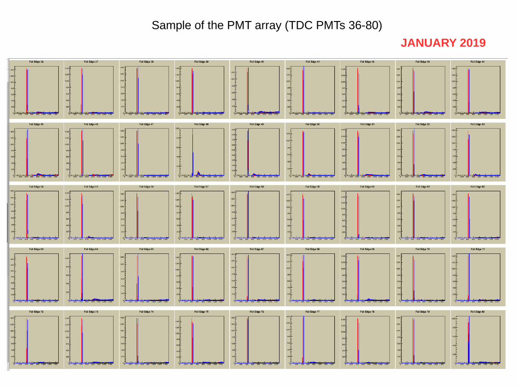
Sample of the PMT array (TDC PMTs 36-80)
JANUARY 2019

σ~2.5ns (FE)
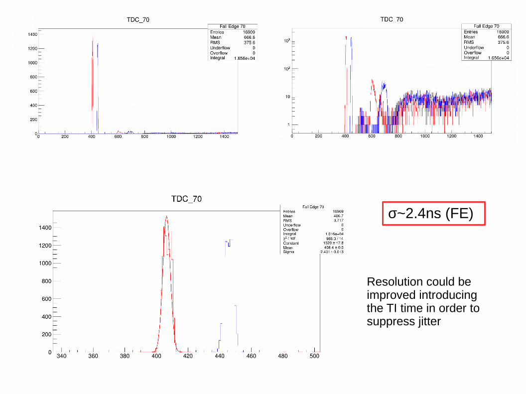
σ~2.4ns (FE)
Resolution could be improved introducing the TI time in order to suppress jitter

We reconnect the cosmic set-up back and make a night run (~7000 triggers). It was NOT enough to get clear statistics for a TDC histogram
Sample of the PMT array (TDC PMTs 36-80)

3 cosmic (?) events. Many events are empty.
Only one VETROC module was used (128 ch) for this run.

● Get more statistics – More efficient cosmic set-up. Most of the triggers have
empty VETROC entries. – HV values/gain check (right now, JMU values).– Check the timing (again).
● Increase number of VETROC channels– Present set-up (mainly due to cabling) allows up to 256
channels.
● Implement a reference channel (TI time information).● A better histogram visualizer (yes... migrate to the
Hall A/C Analyzer).● ...
Things to do...