grippers and vacuum - brammer overview_h… · grippers and vacuum parallel grippers j2 –...
TRANSCRIPT
349
8Grippers
and vacuum
8
350
354
355
356
357
358
359
360
361
362
363
364
365
366
367
367
368
368
369
370
371
371
371
372
374
376
376
377
378
378
379
379
380
380
Sub
ject
to
cha
nge
GrIPPErS AnD VACuuM
Parallel grippersMHZ2 – parallel gripper, 2-finger (narrow finger position)
MHZ2 – parallel gripper, 2-finger (wide finger position)
MHZL2 – parallel gripper, 2-finger, long stroke
MHZj2 – parallel gripper, 2-finger, with protective bellows
MHF2 – parallel gripper, 2-finger
MHL2 – wide opening gripper, 2-finger
MDHR2 & -3 – precision gripper, 2- and 3-finger
Chuck grippersMHS2, -3 & -4 – chuck gripper, 2-, 3- and 4-finger
MHSH3 – chuck gripper with ejector hole/cylinder
MHSj3 – chuck gripper with protective bellows
MHSHj3 – chuck gripper with ejector hole/ cylinder and protective bellows
MHSL3 – chuck gripper with long stroke
angle grippersMHC2 – angle gripper, 2-finger
MHCM – miniature gripper
MHT2 – self-locking gripper, 2-finger
MHY2 – angle gripper, 2-finger, 180°
ContentsMHW2 – angle gripper, 2-finger, 180°
turn and gripper combinationsMRHQ – turn and gripper combination
tool changersMA – tool changer
MA330 – compact tool changer
Non-contact grippersXT661 – non-contact gripper
air nozzlesZH – air nozzle with flow enhancement
Vacuum equipmentZP – vacuum pads
ZP – vacuum pads (large sizes)
AMj – water separator for vacuum
ZF – vacuum filter
ZP2V – vacuum saving valve
ZH – vacuum ejector
Zu – vacuum ejector, in-line
ZL – 3-stage vacuum ejector
IRV – vacuum regulator
ZX – vacuum unit
ZM – 2-stage vacuum unit
351
Always read before handlingThese safety instructions are intended to prevent hazardous situations and/or equipment damage. These instructions indicate the level of potential hazard by labeling • CAuTIOn!, • WArnInG! or • DAnGEr!. To ensure safety, be sure to observe ISO 44141, jIS B 83702 and other safety practices (En ISO 13849-13).
• CAuTIOn! Operator error could result in injury or equipment damage.• WArnInG! Operator error could result in serious injury or loss of life.• DAnGEr! In extreme conditions, there is a possible result of serious injury or loss of life.
1. ISO 4414: Pneumatic fluid power – Recommendations for the application of equipment to transmission and control systems.2. jIS B 8370: Pneumatic system axiom, japan.3. En ISO 13849-1: En ISO 13849-1: Safety of machinery – Safety-related parts of control systems.
• WARNING!The compatibility of pneumatic equipment is the responsibility of the person who designs the pneumatic system or decides its specifications.
Since the products specified here are used in various operating conditions, their compatibility with the specific pneumatic system must be based on specifications or after analysis and/or tests to meet your specific requirements.
Only trained personnel should operate pneumatically operated machinery and equipment.Compressed air can be dangerous if an operator is unfamiliar with it. Assembly, handling or repair of
pneumatic systems should be performed by trained and experienced operators.
Do not service machinery/equipment or attempt to remove components until safety is confirmed.1. Inspection and maintenance of machinery/equipment should only be performed after confirmation of
safe locked-out control positions.2. When equipment is to be removed, confirm the safety process as mentioned above. Cut the supply
pressure from the equipment and exhaust all residual compressed air in the system.3. Before machinery/equipment is re-started, take measures to prevent quick extensions of the cylinder
piston rod etc. (Bleed air into the system gradually to create back-pressure.) (use a soft start valve according to En ISO 13849-1.)
Contact SMC if the product is to be used in any of the following conditions:1. Conditions and environments beyond the given specifications, or if product is used outdoors.2. Installation on equipment in conjunction with atomic energy, railway, air navigation, vehicles, medical
equipment, food and beverage, recreation equipment, emergency stop circuits, press applications, or safety equipment.
3. An application which has the possibility of having negative effects on people, property, or animals, requiring special safety analysis.
SaFety
352
SaFety, GRIPPeRSConstruction
• CAutIoN!1. To minimize the risk of injury, SMC recom-
mends bellows over the gripper moving parts.2. There should also be some form of protection
that ensure that the object handled by the gripper does not cause injury if it drops due to pressure drop in the system.
3. It is of utmost importance that the choice crite-rias given for the different models is used and no parameter is forseen.
4. Also read the general guidelines for pneumatic components that are at the beginning of this catalog.
handling grippers
• WARNING!1. Ensure that the gripper isn’t dropped on the
floor or is subject to shocks during mounting. A small deformation can cause reduced accu-raccy or function.
2. Make sure the screws are tightened with the re-quired torque, and that these values are neither under- or overrun. Too little torque may cause the gripper to move in the application, an ex-cessive torque may cause the gripper to fail or malfunction. Appropriate torque is specified for each gripper.
3. If some kind of gripping tool is applied to the gripper fingers, it is important that the intended holes are used and the permitted torque is not exceeded.
4. Depending on the design of grippers, they can be mounted In different ways. Examples can be axially mounted or mounted in the side. Each model has the relevant tightening torque stated.
Selecting grippers
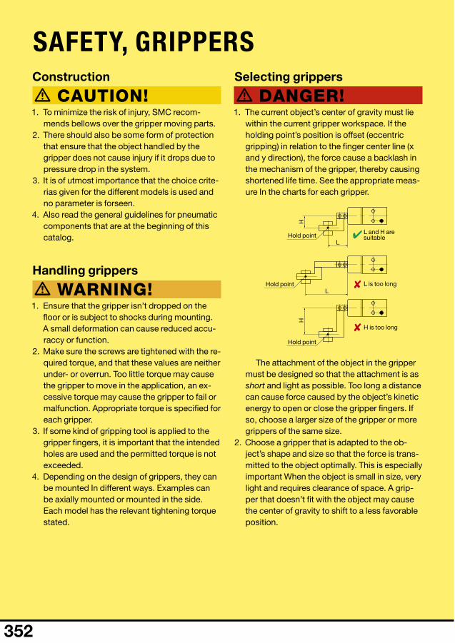
• DANGeR!1. The current object’s center of gravity must lie
within the current gripper workspace. If the holding point’s position is offset (eccentric gripping) in relation to the finger center line (x and y direction), the force cause a backlash in the mechanism of the gripper, thereby causing shortened life time. See the appropriate meas-ure In the charts for each gripper.
The attachment of the object in the gripper must be designed so that the attachment is as short and light as possible. Too long a distance can cause force caused by the object’s kinetic energy to open or close the gripper fingers. If so, choose a larger size of the gripper or more grippers of the same size.
2. Choose a gripper that is adapted to the ob-ject’s shape and size so that the force is trans-mitted to the object optimally. This is especially important When the object is small in size, very light and requires clearance of space. A grip-per that doesn’t fit with the object may cause the center of gravity to shift to a less favorable position.
L and H are suitable
L is too long
H is too long
Hold point
Hold point
Hold point
✘
✘
✔L
H
L
H
353
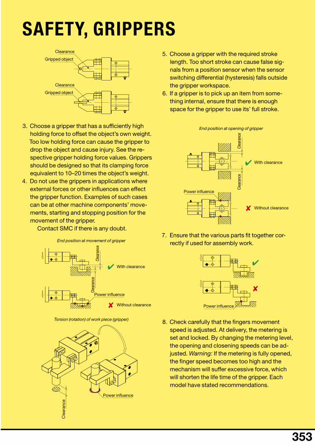
3. Choose a gripper that has a sufficiently high holding force to offset the object’s own weight. Too low holding force can cause the gripper to drop the object and cause injury. See the re-spective gripper holding force values. Grippers should be designed so that its clamping force equivalent to 10–20 times the object’s weight.
4. Do not use the grippers in applications where external forces or other influences can effect the gripper function. Examples of such cases can be at other machine components’ move-ments, starting and stopping position for the movement of the gripper.
Contact SMC if there is any doubt.
5. Choose a gripper with the required stroke length. Too short stroke can cause false sig-nals from a position sensor when the sensor switching differential (hysteresis) falls outside the gripper workspace.
6. If a gripper is to pick up an item from some-thing internal, ensure that there is enough space for the gripper to use its’ full stroke.
7. Ensure that the various parts fit together cor-rectly if used for assembly work.
8. Check carefully that the fingers movement speed is adjusted. At delivery, the metering is set and locked. By changing the metering level, the opening and closening speeds can be ad-justed. Warning: If the metering is fully opened, the finger speed becomes too high and the mechanism will suffer excessive force, which will shorten the life time of the gripper. Each model have stated recommendations.
SaFety, GRIPPeRSClearance
Clearance
Gripped object
Gripped object
With clearance
With clearance
Clea
ranc
e
Clea
ranc
e
Clea
ranc
e
Clea
ranc
e
Cle
aran
ce
Without clearance
Without clearance
Power influence
Power influence
Power influence
Power influence
End position at movement of gripper
End position at opening of gripper
Torsion (rotation) of work piece (gripper)
✔
✘
✔
✘
✔
✘

8
354 ■
5 µm
0.7 MPa (7.0 bar)
Ø10: M3 × 0.5; Ø16–25: M5 × 0.8
MHZ2-10Dn 10 mm 4 mm 9.8 n 17 n 55 gMHZ2-16Dn 16 mm 6 mm 30 n 40 n 115 gMHZ2-20Dn 20 mm 10 mm 42 n 66 n 235 gMHZ2-25Dn 25 mm 14 mm 65 n 104 n 430 g
MHZ2-10Sn 10 mm 4 mm 6.3 n — 55 gMHZ2-16Sn 16 mm 6 mm 24 n — 115 gMHZ2-20Sn 20 mm 10 mm 28 n — 240 gMHZ2-25Sn 25 mm 14 mm 45 n — 435 g
MHZ2-10Cn 10 mm 4 mm — 12 n 55 gMHZ2-16Cn 16 mm 6 mm — 31 n 115 gMHZ2-20Cn 20 mm 10 mm — 56 n 240 gMHZ2-25Cn 25 mm 14 mm — 83 n 430 g
D-M9PWLD-M9PWSAPCD-M9PWSDPC
BMG2-012 10 mm
Sub
ject
to
cha
nge
GrIPPErS AnD VACuuM
= DElIVEry EX-STOCK FOr MOrE InFO, ASK ThE SMC EXPErTS: PhOnE +31 (0) 20 531 88 88 / [email protected]
MhZ2 – parallel gripper, 2-finger (narrow finger position)
Medium Compressed air, lubricated or unlubricated (dry)Degree of filtration
Function Single acting/double actingMax. working pressure
Min. working pressure
Single acting – Ø10: 0.35 MPa (3.5 bar); Ø16–25: 0.25 MPa (2.5 bar)
Double acting – Ø10: 0.2 MPa (2.0 bar); Ø16–25: 0.1 MPa (1.0 bar)
Max. frequency 180 strokes/minuteOperating temperature –10 to 60 °C
Air connection Guide type Ball bearing guide
■ High precision ■ Compact design ■ Repeatability ±0.01 mm
Parallel gripper – narrow finger positionDouble acting
Part number Bore size Stroke External
grip1Internal
grip1 Weight
Single acting, normally open narrow design
Part number Bore size Stroke External
grip1Internal
grip1 Weight
Single acting, normally closed narrow design
Part number Bore size Stroke External
grip1Internal
grip1 Weight
1. Clamping force is given per finger, at 0.5 MPa and an assumed gripping distance, see catalogue for details.
Note! Replaces MHQ2 with regard to dimensions
Sensors – 24 VDCFor bore size 16–25 mm
Part number TypeElectronic PnP, LED (2-colour), with 3 m cableElectronic PnP, M8 connector, LED (2-colour)Electronic PnP, M12 connector, LED (2-colour)
Bracket for sensorsPart number Bore size
Recommended: D-M9-W, sensor with 2-colour indication. For other sensors, see end of chapter 6.
8
355■
5 µm
0.7 MPa (7.0 bar)
Ø6–10: M3 × 0.5; Ø16–25: M5 × 0.8; Ø32–40: Rc1/8
MHZ2-6D 6 mm 4 mm 3.3 n — 27 gMHZ2-10D 10 mm 4 mm 9.8 n 17 n 55 gMHZ2-16D 16 mm 6 mm 30 n 40 n 115 gMHZ2-20D 20 mm 10 mm 42 n 66 n 235 gMHZ2-25D 25 mm 14 mm 65 n 104 n 430 gMHZ2-32D 32 mm 22 mm 158 n — 715 gMHZ2-40D 40 mm 30 mm 254 n — 1275 g
MHZ2-6S 6 mm 4 mm — — 27 gMHZ2-10S 10 mm 4 mm 6.3 n — 55 gMHZ2-16S 16 mm 6 mm 24 n — 115 gMHZ2-20S 20 mm 10 mm 28 n — 240 gMHZ2-25S 25 mm 14 mm 45 n — 435 gMHZ2-32S 32 mm 22 mm 161 n — 760 gMHZ2-40S 40 mm 30 mm 267 n — 1370 g
MHZ2-6C 6 mm 4 mm — — 27 gMHZ2-10C 10 mm 4 mm — 12 n 55 gMHZ2-16C 16 mm 6 mm — 31 n 115 gMHZ2-20C 20 mm 10 mm — 56 n 240 gMHZ2-25C 25 mm 14 mm — 83 n 430 gMHZ2-32C 32 mm 22 mm — 161 n 760 gMHZ2-40C 40 mm 30 mm — 267 n 1370 g
D-M9PWLD-M9PWSAPCD-M9PWSDPC
BMG2-012 10 mm
Sub
ject
to
cha
nge
GrIPPErS AnD VACuuM
= DElIVEry EX-STOCK FOr MOrE InFO, ASK ThE SMC EXPErTS: PhOnE +31 (0) 20 531 88 88 / [email protected]
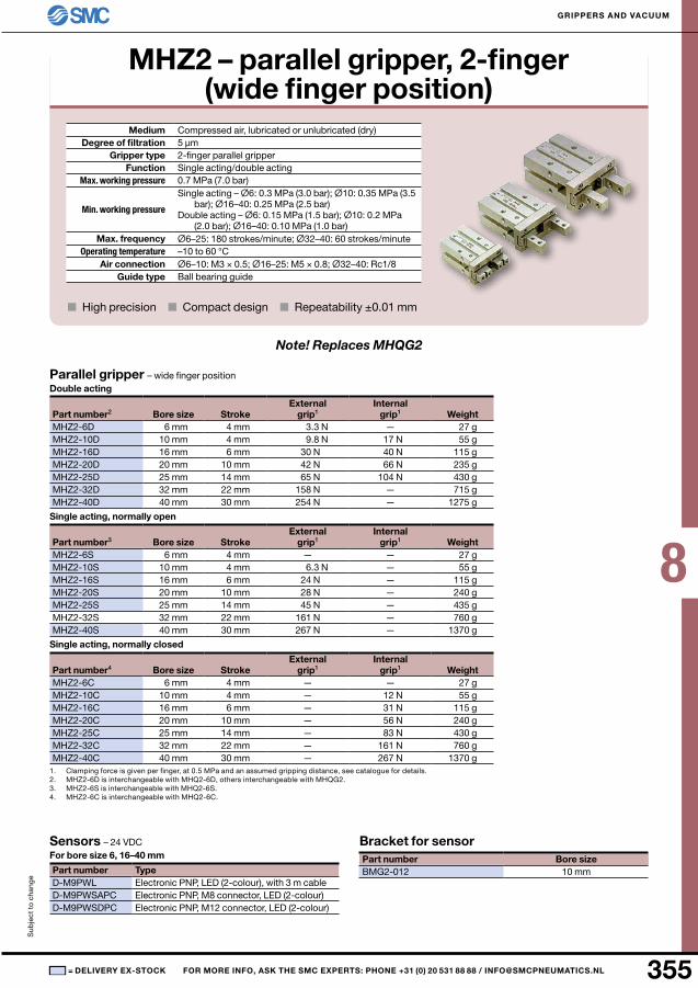
MhZ2 – parallel gripper, 2-finger (wide finger position)
Medium Compressed air, lubricated or unlubricated (dry)Degree of filtration
Gripper type 2-finger parallel gripperFunction Single acting/double acting
Max. working pressure
Min. working pressure
Single acting – Ø6: 0.3 MPa (3.0 bar); Ø10: 0.35 MPa (3.5 bar); Ø16–40: 0.25 MPa (2.5 bar)
Double acting – Ø6: 0.15 MPa (1.5 bar); Ø10: 0.2 MPa (2.0 bar); Ø16–40: 0.10 MPa (1.0 bar)
Max. frequency Ø6–25: 180 strokes/minute; Ø32–40: 60 strokes/minuteOperating temperature –10 to 60 °C
Air connection Guide type Ball bearing guide
■ High precision ■ Compact design ■ Repeatability ±0.01 mm
Parallel gripper – wide finger positionDouble acting
Part number2 Bore size Stroke External
grip1Internal
grip1 Weight
Single acting, normally open
Part number3 Bore size Stroke External
grip1Internal
grip1 Weight
Single acting, normally closed
Part number4 Bore size Stroke External
grip1Internal
grip1 Weight
1. Clamping force is given per finger, at 0.5 MPa and an assumed gripping distance, see catalogue for details.2. MHZ2-6D is interchangeable with MHQ2-6D, others interchangeable with MHQG2.3. MHZ2-6S is interchangeable with MHQ2-6S.4. MHZ2-6C is interchangeable with MHQ2-6C.
Note! Replaces MHQG2
Sensors – 24 VDC For bore size 6, 16–40 mm
Part number TypeElectronic PnP, LED (2-colour), with 3 m cableElectronic PnP, M8 connector, LED (2-colour)Electronic PnP, M12 connector, LED (2-colour)
Bracket for sensorPart number Bore size
8
356 ■
5 µm
0.7 MPa (7.0 bar)
Ø10: M3 × 0.5; Ø16–25: M5 × 0.8
MHZL2-10D 10 mm 8 mm 11 n — 60 gMHZL2-16D 16 mm 12 mm 34 n — 135 gMHZL2-20D 20 mm 18 mm 42 n — 270 gMHZL2-25D 25 mm 22 mm 63 n — 470 g
MHZL2-10S 10 mm 8 mm 7.1 n — 70 gMHZL2-16S 16 mm 12 mm 27 n — 145 gMHZL2-20S 20 mm 18 mm 33 n — 290 gMHZL2-25S 25 mm 22 mm 50 n — 515 g
MHZL2-10C 10 mm 8 mm — 13 n 70 gMHZL2-16C 16 mm 12 mm — 38 n 145 gMHZL2-20C 20 mm 18 mm — 57 n 290 gMHZL2-25C 25 mm 22 mm — 85 n 515 g
D-M9PWLD-M9PWSAPCD-M9PWSDPC
BMG2-012 10 mm
Sub
ject
to
cha
nge
GrIPPErS AnD VACuuM
= DElIVEry EX-STOCK FOr MOrE InFO, ASK ThE SMC EXPErTS: PhOnE +31 (0) 20 531 88 88 / [email protected]
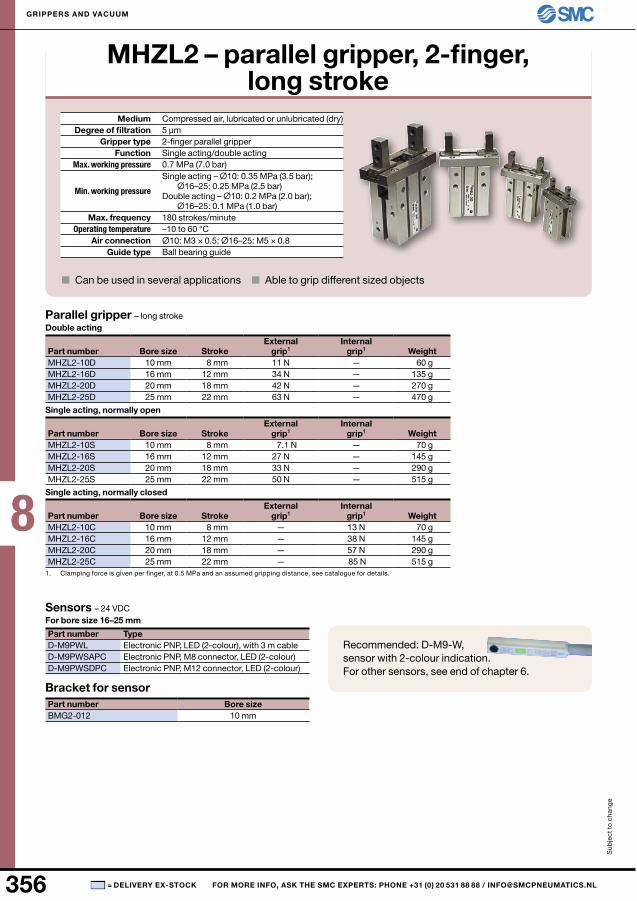
MhZl2 – parallel gripper, 2-finger, long stroke
Medium Compressed air, lubricated or unlubricated (dry)Degree of filtration
Gripper type 2-finger parallel gripperFunction Single acting/double acting
Max. working pressure
Min. working pressure
Single acting – Ø10: 0.35 MPa (3.5 bar); Ø16–25: 0.25 MPa (2.5 bar)
Double acting – Ø10: 0.2 MPa (2.0 bar); Ø16–25: 0.1 MPa (1.0 bar)
Max. frequency 180 strokes/minuteOperating temperature –10 to 60 °C
Air connection Guide type Ball bearing guide
■ Can be used in several applications ■ Able to grip different sized objects
Parallel gripper – long strokeDouble acting
Part number Bore size Stroke External
grip1Internal
grip1 Weight
Single acting, normally open
Part number Bore size Stroke External
grip1Internal
grip1 Weight
Single acting, normally closed
Part number Bore size Stroke External
grip1Internal
grip1 Weight
1. Clamping force is given per finger, at 0.5 MPa and an assumed gripping distance, see catalogue for details.
Sensors – 24 VDCFor bore size 16–25 mm
Part number TypeElectronic PnP, LED (2-colour), with 3 m cableElectronic PnP, M8 connector, LED (2-colour)Electronic PnP, M12 connector, LED (2-colour)
Bracket for sensorPart number Bore size
Recommended: D-M9-W, sensor with 2-colour indication. For other sensors, see end of chapter 6.
8
357■
5 µm
0.7 MPa (7.0 bar)
Ø10: M3 × 0.5; Ø16–25: M5 × 0.8
MHZj2-6D 6 mm 4 mm 3.3 n — 28 gMHZj2-10D 10 mm 4 mm 9.8 n 17 n 60 gMHZj2-16D 16 mm 6 mm 30 n 40 n 130 gMHZj2-20D 20 mm 10 mm 42 n 66 n 250 gMHZj2-25D 25 mm 14 mm 65 n 104 n 460 g
MHZj2-6S 6 mm 4 mm — — 28 gMHZj2-10S 10 mm 4 mm 6.3 n — 60 gMHZj2-16S 16 mm 6 mm 24 n — 130 gMHZj2-20S 20 mm 10 mm 28 n — 255 gMHZj2-25S 25 mm 14 mm 45 n — 465 g
MHZj2-6C 6 mm 4 mm — — 28 gMHZj2-10C 10 mm 4 mm — 12 n 60 gMHZj2-16C 16 mm 6 mm — 31 n 130 gMHZj2-20C 20 mm 10 mm — 56 n 255 gMHZj2-25C 25 mm 14 mm — 83 n 460 g
D-M9PWLD-M9PWSAPCD-M9PWSDPC
BMG2-012 10 mm
Sub
ject
to
cha
nge
GrIPPErS AnD VACuuM
= DElIVEry EX-STOCK FOr MOrE InFO, ASK ThE SMC EXPErTS: PhOnE +31 (0) 20 531 88 88 / [email protected]
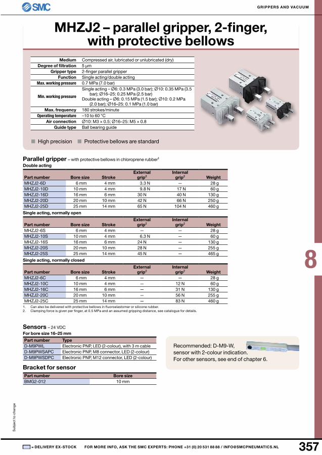
MhZJ2 – parallel gripper, 2-finger, with protective bellows
Medium Compressed air, lubricated or unlubricated (dry)Degree of filtration
Gripper type 2-finger parallel gripperFunction Single acting/double acting
Max. working pressure
Min. working pressure
Single acting – Ø6: 0.3 MPa (3.0 bar); Ø10: 0.35 MPa (3.5 bar); Ø16–25: 0.25 MPa (2.5 bar)
Double acting – Ø6: 0.15 MPa (1.5 bar); Ø10: 0.2 MPa (2.0 bar); Ø16–25: 0.1 MPa (1.0 bar)
Max. frequency 180 strokes/minuteOperating temperature –10 to 60 °C
Air connection Guide type Ball bearing guide
■ High precision ■ Protective bellows are standard
Parallel gripper – with protective bellows in chloroprene rubber1
Double acting
Part number Bore size Stroke External
grip2Internal
grip2 Weight
Single acting, normally open
Part number Bore size Stroke External
grip2Internal
grip2 Weight
Single acting, normally closed
Part number Bore size Stroke External
grip2Internal
grip2 Weight
1. Can also be delivered with protective bellows in fluoroelastomer or silicone rubber.2. Clamping force is given per finger, at 0.5 MPa and an assumed gripping distance, see catalogue for details.
Sensors – 24 VDCFor bore size 16–25 mm
Part number TypeElectronic PnP, LED (2-colour), with 3 m cableElectronic PnP, M8 connector, LED (2-colour)Electronic PnP, M12 connector, LED (2-colour)
Bracket for sensorPart number Bore size
Recommended: D-M9-W, sensor with 2-colour indication. For other sensors, see end of chapter 6.
8
358 ■
5 µm
0.7 MPa (7 bar)Ø8: 0.15 MPa (1.5 bar); Ø12–20: 0.1 MPa (1 bar)
Ø8: M3 × 0.5; Ø12–20: M5 × 0.8
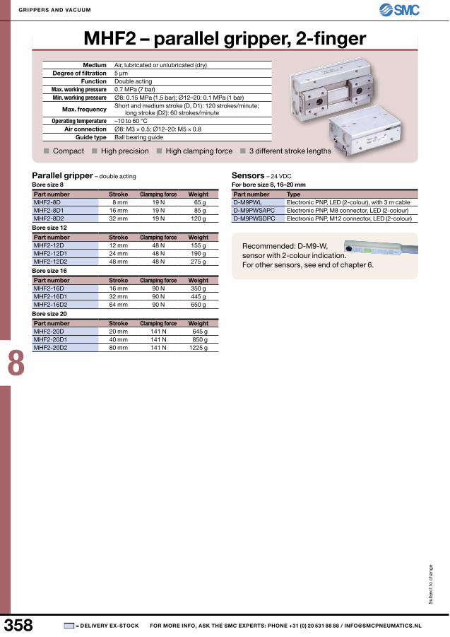
MHF2-8D 8 mm 19 n 65 gMHF2-8D1 16 mm 19 n 85 gMHF2-8D2 32 mm 19 n 120 g
MHF2-12D 12 mm 48 n 155 gMHF2-12D1 24 mm 48 n 190 gMHF2-12D2 48 mm 48 n 275 g
MHF2-16D 16 mm 90 n 350 gMHF2-16D1 32 mm 90 n 445 gMHF2-16D2 64 mm 90 n 650 g
MHF2-20D 20 mm 141 n 645 gMHF2-20D1 40 mm 141 n 850 gMHF2-20D2 80 mm 141 n 1225 g
D-M9PWLD-M9PWSAPCD-M9PWSDPC
Sub
ject
to
cha
nge
GrIPPErS AnD VACuuM
= DElIVEry EX-STOCK FOr MOrE InFO, ASK ThE SMC EXPErTS: PhOnE +31 (0) 20 531 88 88 / [email protected]
MhF2 – parallel gripper, 2-fingerMedium Air, lubricated or unlubricated (dry)
Degree of filtrationFunction Double acting
Max. working pressure Min. working pressure
Max. frequency Short and medium stroke (D, D1): 120 strokes/minute; long stroke (D2): 60 strokes/minute
Operating temperature –10 to 60 °CAir connection
Guide type Ball bearing guide
■ Compact ■ High precision ■ High clamping force ■ 3 different stroke lengths
Parallel gripper – double acting Bore size 8
Part number Stroke Clamping force Weight
Bore size 12
Part number Stroke Clamping force Weight
Bore size 16
Part number Stroke Clamping force Weight
Bore size 20
Part number Stroke Clamping force Weight
Sensors – 24 VDC For bore size 8, 16–20 mm
Part number TypeElectronic PnP, LED (2-colour), with 3 m cableElectronic PnP, M8 connector, LED (2-colour)Electronic PnP, M12 connector, LED (2-colour)
Recommended: D-M9-W, sensor with 2-colour indication. For other sensors, see end of chapter 6.
8
359■
5 µm
0.6 MPa (6.0 bar)0.1 MPa (1.0 bar)
Ø10–25: M5 × 0.8; Ø32–40: G1/8
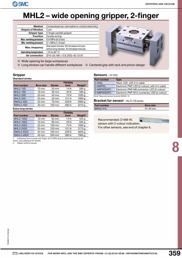
MHL2-10D 10 mm 20 mm 14 n 280 gMHL2-16D 16 mm 30 mm 45 n 585 gMHL2-20D 20 mm 40 mm 74 n 1025 gMHL2-25D 25 mm 50 mm 131 n 1690 gEMHL2-32D 32 mm 70 mm 228 n 2905 gEMHL2-40D 40 mm 100 mm 396 n 5270 g
MHL2-10D2 10 mm 60 mm 14 n 425 gMHL2-16D2 16 mm 80 mm 45 n 935 gMHL2-20D2 20 mm 100 mm 74 n 1690 gMHL2-25D2 25 mm 120 mm 131 n 2775 gEMHL2-32D2 32 mm 160 mm 228 n 4655 gEMHL2-40D2 40 mm 200 mm 396 n 7905 g
D-A93LD-M9PWLD-M9PWSAPCD-M9PWSDPC
BMG2-012 10–40 mm
Sub
ject
to
cha
nge
GrIPPErS AnD VACuuM
= DElIVEry EX-STOCK FOr MOrE InFO, ASK ThE SMC EXPErTS: PhOnE +31 (0) 20 531 88 88 / [email protected]
Mhl2 – wide opening gripper, 2-fingerMedium Compressed air, lubricated or unlubricated (dry)
Degree of filtrationGripper type 2-finger parallel gripper
Function Double actingMax. working pressureMin. working pressure
Max. frequency Standard stroke: 60 strokes/minute; extra long stroke: 40 strokes/minute
Operating temperature –10 to 60 °CAir connection
■ Wide opening for large workpieces■ Long strokes can handle different workpieces ■ Centered grip with rack and pinion design
GripperStandard stroke
Part number Bore size Stroke Clamping
force1 Weight2
Extra long stroke
Part number Bore size StrokeClamping
force1 Weight2
1. Clamping force is given per finger, at 0.5 MPa and an assumed gripping dis-tance, see catalogue for details.2. Weight without sensor.
Sensors – 24 VDC
Part number TypeReed, LED, with 3 m cableElectronic PnP, LED (2-colour), with 3 m cableElectronic PnP, M8 connector, LED (2-colour)Electronic PnP, M12 connector, LED (2-colour)
Note! Requires sensor bracket BMG2-12.
Bracket for sensor – fits D-9 series
Part number Bore size
Recommended: D-M9-W, sensor with 2-colour indication. For other sensors, see end of chapter 6.
8
360 ■
5 µm
0.6 MPa (6.0 bar)Ø10: 0.2 MPa (2.0 bar); Ø15–30: 0.15 MPa (1.5 bar)
Ø10–15: M3 × 0.5; Ø 20–30: M5 × 0.8
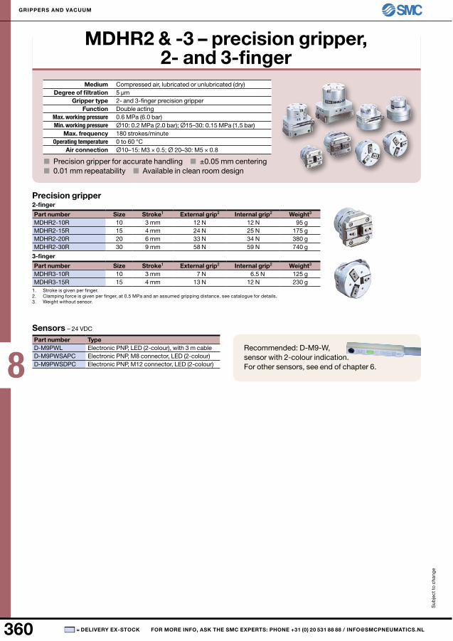
MDHR2-10R 10 3 mm 12 n 12 n 95 gMDHR2-15R 15 4 mm 24 n 25 n 175 gMDHR2-20R 20 6 mm 33 n 34 n 380 gMDHR2-30R 30 9 mm 58 n 59 n 740 g
MDHR3-10R 10 3 mm 7 n 6.5 n 125 gMDHR3-15R 15 4 mm 13 n 12 n 230 g
D-M9PWLD-M9PWSAPCD-M9PWSDPC
Sub
ject
to
cha
nge
GrIPPErS AnD VACuuM
= DElIVEry EX-STOCK FOr MOrE InFO, ASK ThE SMC EXPErTS: PhOnE +31 (0) 20 531 88 88 / [email protected]
MDhr2 & -3 – precision gripper, 2- and 3-finger
Medium Compressed air, lubricated or unlubricated (dry)Degree of filtration
Gripper type 2- and 3-finger precision gripperFunction Double acting
Max. working pressureMin. working pressure
Max. frequency 180 strokes/minuteOperating temperature 0 to 60 °C
Air connection
■ Precision gripper for accurate handling ■ ±0.05 mm centering■ 0.01 mm repeatability ■ Available in clean room design
Precision gripper2-finger
Part number Size Stroke1 External grip2 Internal grip2 Weight3
3-finger
Part number Size Stroke1 External grip2 Internal grip2 Weight3
1. Stroke is given per finger.2. Clamping force is given per finger, at 0.5 MPa and an assumed gripping distance, see catalogue for details.3. Weight without sensor.
Sensors – 24 VDC
Part number TypeElectronic PnP, LED (2-colour), with 3 m cableElectronic PnP, M8 connector, LED (2-colour)Electronic PnP, M12 connector, LED (2-colour)
Recommended: D-M9-W, sensor with 2-colour indication. For other sensors, see end of chapter 6.
8
361■
5 µm
0.6 MPa (6.0 bar)Ø16–25: 0.2 MPa (2.0 bar); Ø32–125: 0.1 MPa (1.0 bar)
Ø16: M3 × 0.5; Ø20–63: M5 × 0.8; Ø80: G1/8; Ø100: G1/4; Ø125: G3/8
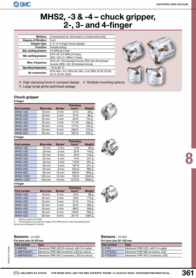
MHS2-16D 16 mm 2 mm 21 n 58 gMHS2-20D 20 mm 2 mm 37 n 96 gMHS2-25D 25 mm 3 mm 63 n 134 gMHS2-32D 32 mm 4 mm 111 n 265 gMHS2-40D 40 mm 4 mm 177 n 345 gMHS2-50D 50 mm 6 mm 280 n 515 gMHS2-63D 63 mm 8 mm 502 n 952 g
MHS3-16D 16 mm 2 mm 14 n 60 gMHS3-20D 20 mm 2 mm 25 n 100 gMHS3-25D 25 mm 3 mm 42 n 140 gMHS3-32D 32 mm 4 mm 74 n 237 gMHS3-40D 40 mm 4 mm 118 n 351 gMHS3-50D 50 mm 6 mm 187 n 541 gMHS3-63D 63 mm 8 mm 335 n 992 gMHS3-80D 80 mm 10 mm 500 n 1850 gMHS3-100D 100 mm 12 mm 750 n 3340 gMHS3-125D 125 mm 16 mm 1270 n 6360 g
MHS4-16D 16 mm 2 mm 10 n 66 gMHS4-20D 20 mm 2 mm 19 n 110 gMHS4-25D 25 mm 3 mm 31 n 154 gMHS4-32D 32 mm 4 mm 55 n 300 gMHS4-40D 40 mm 4 mm 88 n 390 gMHS4-50D 50 mm 6 mm 140 n 590 gMHS4-63D 63 mm 8 mm 251 n 1095 g
D-M9PWLD-M9PWSAPCD-M9PWSDPC
D-Y7PLD-Y7PSAPCD-Y7PSDPC
Sub
ject
to
cha
nge
GrIPPErS AnD VACuuM
= DElIVEry EX-STOCK FOr MOrE InFO, ASK ThE SMC EXPErTS: PhOnE +31 (0) 20 531 88 88 / [email protected]
MhS2, -3 & -4 – chuck gripper, 2-, 3- and 4-finger
Medium Compressed air, lubricated or unlubricated (dry)Degree of filtration
Gripper type 2, 3- or 4-finger chuck gripperFunction Double acting
Max. working pressure
Min. working pressure
Max. frequency Ø16–25: 120 strokes/minute; Ø32–63: 60 strokes/minute; Ø80–125: 30 strokes/minute
Operating temperature –10 to 60 °C
Air connection
■ High clamping force in compact design ■ Multiple mounting options■ Large range gives optimized useage
Chuck gripper2-finger
Part number Bore size Stroke1Clamping
force2 Weight
3-finger
Part number Bore size Stroke1Clamping
force2 Weight
4-finger
Part number Bore size Stroke1Clamping
force2 Weight
1. Stroke is given per finger.2. Clamping force is given per finger, at 0.5 MPa and an assumed gripping dis-tance, see catalogue for details.
Sensors – 24 VDCFor bore size 16–25 mm
Part number TypeElectronic PnP, LED (2-colour), with 3 m cableElectronic PnP, M8 connector, LED (2-colour)Electronic PnP, M12 connector, LED (2-colour)
Sensors – 24 VDCFor bore size 32–125 mm
Part number TypeElectronic PnP, LED, with 3 m cableElectronic PnP, M8 connector, LEDElectronic PnP, M12 connector, LED
8
362 ■
5 µm
0.6 MPa (6.0 bar)Ø16–25: 0.2 MPa (2.0 bar); Ø32–80: 0.1 MPa (1.0 bar)
Ø16: M3 × 0.5; Ø20–63: M5 × 0.8; Ø80: G1/8
MHSH3-16D 16 mm 4 mm 9 n 90 gMHSH3-20D 20 mm 4 mm 21 n 140 gMHSH3-25D 25 mm 6 mm 36 n 220 gMHSH3-32D 32 mm 8 mm 62 n 410 gMHSH3-40D 40 mm 8 mm 97 n 570 gMHSH3-50D 50 mm 12 mm 155 n 970 gMHSH3-63D 63 mm 16 mm 280 n 1650 gMHSH3-80D 80 mm 20 mm 400 n 2920 g
MHSH3-32DA 32 mm 8 mm 62 n 940 gMHSH3-40DA 40 mm 8 mm 97 n 1340 gMHSH3-50DA 50 mm 12 mm 155 n 2300 gMHSH3-63DA 63 mm 16 mm 280 n 3950 gMHSH3-80DA 80 mm 20 mm 400 n 6920 g
MHSH3-32DB 32 mm 8 mm 62 n 910 gMHSH3-40DB 40 mm 8 mm 97 n 1310 gMHSH3-50DB 50 mm 12 mm 155 n 2260 gMHSH3-63DB 63 mm 16 mm 280 n 3900 gMHSH3-80DB 80 mm 20 mm 400 n 6920 g
D-M9PWLD-M9PWSAPCD-M9PWSDPC
Sub
ject
to
cha
nge
GrIPPErS AnD VACuuM
= DElIVEry EX-STOCK FOr MOrE InFO, ASK ThE SMC EXPErTS: PhOnE +31 (0) 20 531 88 88 / [email protected]
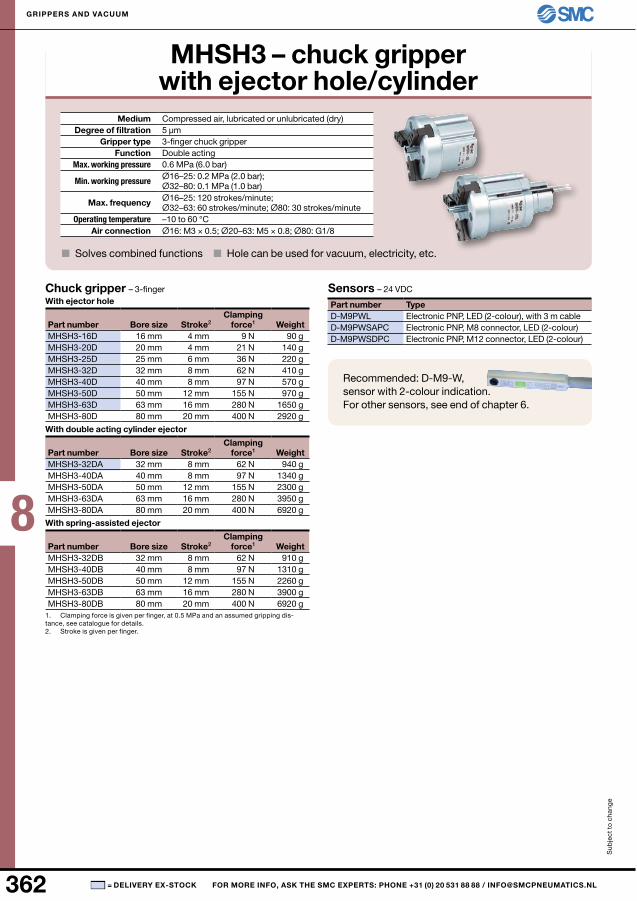
MhSh3 – chuck gripper with ejector hole/cylinder
Medium Compressed air, lubricated or unlubricated (dry)Degree of filtration
Gripper type 3-finger chuck gripperFunction Double acting
Max. working pressure
Min. working pressure
Max. frequency Ø16–25: 120 strokes/minute; Ø32–63: 60 strokes/minute; Ø80: 30 strokes/minute
Operating temperature –10 to 60 °CAir connection
■ Solves combined functions ■ Hole can be used for vacuum, electricity, etc.
Chuck gripper – 3-fingerWith ejector hole
Part number Bore size Stroke2Clamping
force1 Weight
With double acting cylinder ejector
Part number Bore size Stroke2Clamping
force1 Weight
With spring-assisted ejector
Part number Bore size Stroke2Clamping
force1 Weight
1. Clamping force is given per finger, at 0.5 MPa and an assumed gripping dis-tance, see catalogue for details.2. Stroke is given per finger.
Sensors – 24 VDC
Part number TypeElectronic PnP, LED (2-colour), with 3 m cableElectronic PnP, M8 connector, LED (2-colour)Electronic PnP, M12 connector, LED (2-colour)
Recommended: D-M9-W, sensor with 2-colour indication. For other sensors, see end of chapter 6.
8
363■
5 µm
0.6 MPa (6.0 bar)Ø16–25: 0.2 MPa (2.0 bar); Ø32–80: 0.1 MPa (1.0 bar)
Ø16: M3 × 0.5; Ø20–63: M5 × 0.8; Ø80: Rc1/8
MHSj3-16D 16 mm 2 mm 9 n 95 gMHSj3-20D 20 mm 2 mm 21 n 150 gMHSj3-25D 25 mm 3 mm 36 n 230 gMHSj3-32D 32 mm 4 mm 62 n 440 gMHSj3-40D 40 mm 4 mm 97 n 620 gMHSj3-50D 50 mm 6 mm 155 n 1050 gMHSj3-63D 63 mm 8 mm 280 n 1800 gMHSj3-80D 80 mm 10 mm 400 n 3200 g
16 mm MHSj3-j16 MHSj3-j16F MHSj3-j16S20 mm MHSj3-j20 MHSj3-j20F MHSj3-j20S25 mm MHSj3-j25 MHSj3-j25F MHSj3-j25S32 mm MHSj3-j32 MHSj3-j32F MHSj3-j32S40 mm MHSj3-j40 MHSj3-j40F MHSj3-j40S50 mm MHSj3-j50 MHSj3-j50F MHSj3-j50S63 mm MHSj3-j63 MHSj3-j63F MHSj3-j63S80 mm MHSj3-j80 MHSj3-j80F MHSj3-j80S
D-M9PWLD-M9PWSAPCD-M9PWSDPC
Sub
ject
to
cha
nge
GrIPPErS AnD VACuuM
= DElIVEry EX-STOCK FOr MOrE InFO, ASK ThE SMC EXPErTS: PhOnE +31 (0) 20 531 88 88 / [email protected]
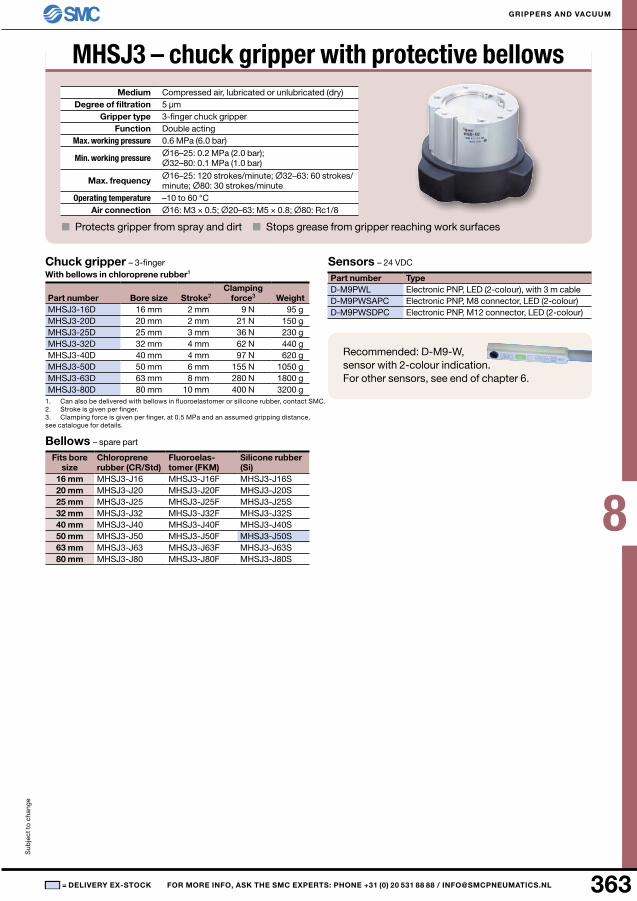
MHSJ3 – chuck gripper with protective bellowsMedium Compressed air, lubricated or unlubricated (dry)
Degree of filtrationGripper type 3-finger chuck gripper
Function Double actingMax. working pressure
Min. working pressure
Max. frequency Ø16–25: 120 strokes/minute; Ø32–63: 60 strokes/minute; Ø80: 30 strokes/minute
Operating temperature –10 to 60 °CAir connection
■ Protects gripper from spray and dirt ■ Stops grease from gripper reaching work surfaces
Chuck gripper – 3-finger With bellows in chloroprene rubber1
Part number Bore size Stroke2 Clamping
force3 Weight
1. Can also be delivered with bellows in fluoroelastomer or silicone rubber, contact SMC.2. Stroke is given per finger.3. Clamping force is given per finger, at 0.5 MPa and an assumed gripping distance, see catalogue for details.
Bellows – spare part
Fits bore size
Chloroprene rubber (Cr/Std)
Fluoroelas-tomer (FKM)
Silicone rubber (Si)
Sensors – 24 VDC
Part number TypeElectronic PnP, LED (2-colour), with 3 m cableElectronic PnP, M8 connector, LED (2-colour)Electronic PnP, M12 connector, LED (2-colour)
Recommended: D-M9-W, sensor with 2-colour indication. For other sensors, see end of chapter 6.
8
364 ■
5 µm
0.6 MPa (6.0 bar)0.1 MPa (1.0 bar)
Ø16: M3 × 0.5; Ø20–63: M5 × 0.8; Ø80: Rc1/8
MHSHj3-32D 32 mm 4 mm 62 n 430 gMHSHj3-40D 40 mm 4 mm 97 n 600 gMHSHj3-50D 50 mm 6 mm 155 n 1020 gMHSHj3-63D 63 mm 8 mm 280 n 1710 gMHSHj3-80D 80 mm 10 mm 400 n 3040 g
MHSHj3-32DA 32 mm 4 mm 62 n 550 gMHSHj3-40DA 40 mm 4 mm 97 n 800 gMHSHj3-50DA 50 mm 6 mm 155 n 1380 gMHSHj3-63DA 63 mm 8 mm 280 n 2360 gMHSHj3-80DA 80 mm 10 mm 400 n 4120 g
MHSHj3-32DB 32 mm 4 mm 62 n 520 gMHSHj3-40DB 40 mm 4 mm 97 n 770 gMHSHj3-50DB 50 mm 6 mm 155 n 1340 gMHSHj3-63DB 63 mm 8 mm 280 n 2310 gMHSHj3-80DB 80 mm 10 mm 400 n 4120 g
D-M9PWLD-M9PWSAPCD-M9PWSDPC
Sub
ject
to
cha
nge
GrIPPErS AnD VACuuM
= DElIVEry EX-STOCK FOr MOrE InFO, ASK ThE SMC EXPErTS: PhOnE +31 (0) 20 531 88 88 / [email protected]
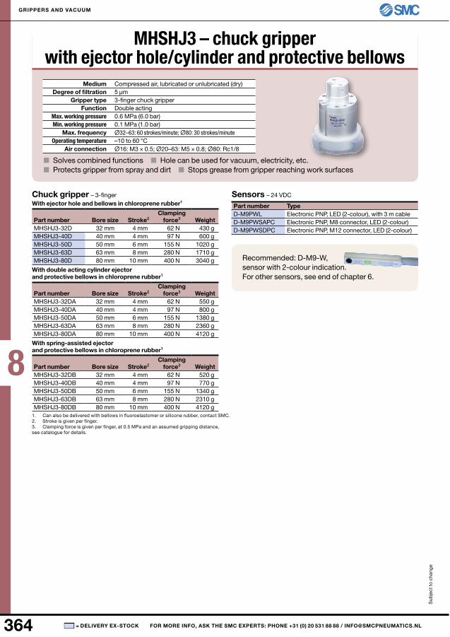
MHSHJ3 – chuck gripper with ejector hole/cylinder and protective bellows
Medium Compressed air, lubricated or unlubricated (dry)Degree of filtration
Gripper type 3-finger chuck gripperFunction Double acting
Max. working pressureMin. working pressure
Max. frequency Ø32–63: 60 strokes/minute; Ø80: 30 strokes/minuteOperating temperature –10 to 60 °C
Air connection
■ Solves combined functions ■ Hole can be used for vacuum, electricity, etc.■ Protects gripper from spray and dirt ■ Stops grease from gripper reaching work surfaces
Chuck gripper – 3-finger With ejector hole and bellows in chloroprene rubber1
Part number Bore size Stroke2 Clamping
force3 Weight
With double acting cylinder ejector and protective bellows in chloroprene rubber1
Part number Bore size Stroke2 Clamping
force3 Weight
With spring-assisted ejector and protective bellows in chloroprene rubber1
Part number Bore size Stroke2 Clamping
force3 Weight
1. Can also be delivered with bellows in fluoroelastomer or silicone rubber, contact SMC.2. Stroke is given per finger.3. Clamping force is given per finger, at 0.5 MPa and an assumed gripping distance, see catalogue for details.
Sensors – 24 VDC
Part number TypeElectronic PnP, LED (2-colour), with 3 m cableElectronic PnP, M8 connector, LED (2-colour)Electronic PnP, M12 connector, LED (2-colour)
Recommended: D-M9-W, sensor with 2-colour indication. For other sensors, see end of chapter 6.
8
365■
5 µm
0.6 MPa (6.0 bar)Ø16–25: 0.2 MPa (2.0 bar); Ø32–125: 0.1 MPa (1.0 bar)
Ø16: M3 × 0.5; Ø20–63: M5 × 0.8; Ø80: Rc1/8; Ø100: Rc1/4; Ø125: Rc3/8
MHSL3-16D 16 mm 5 mm 14 n 80 gMHSL3-20D 20 mm 5 mm 25 n 135 gMHSL3-25D 25 mm 6 mm 42 n 180 gMHSL3-32D 32 mm 8 mm 74 n 370 gMHSL3-40D 40 mm 10 mm 118 n 550 gMHSL3-50D 50 mm 14 mm 187 n 930 gMHSL3-63D 63 mm 16 mm 335 n 1550 gMHSL3-80D 80 mm 20 mm 500 n 2850 gMHSL3-100D 100 mm 24 mm 750 n 5500 gMHSL3-125D 125 mm 32 mm 1270 n 11300 g
D-M9PWLD-M9PWSAPCD-M9PWSDPC
D-Y7PLD-Y7PSAPCD-Y7PSDPC
Sub
ject
to
cha
nge
GrIPPErS AnD VACuuM
= DElIVEry EX-STOCK FOr MOrE InFO, ASK ThE SMC EXPErTS: PhOnE +31 (0) 20 531 88 88 / [email protected]
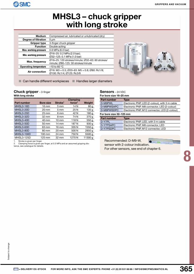
MhSl3 – chuck gripper with long stroke
Medium Compressed air, lubricated or unlubricated (dry)Degree of filtration
Gripper type 3-finger chuck gripperFunction Double acting
Max. working pressure
Min. working pressure
Max. frequency Ø16–25: 120 strokes/minute; Ø32–63: 60 strokes/minute; Ø80–125: 30 strokes/minute
Operating temperature –10 to 60 °C
Air connection
■ Can handle different workpieces ■ Handles larger diameters
Chuck gripper – 3-finger With long stroke
Part number Bore size Stroke1 Clamping
force2 Weight
1. Stroke is given per finger.2. Clamping force is given per finger, at 0.5 MPa and an assumed gripping dis-tance, see catalogue for details.
Sensors – 24 VDC For bore size 16–25 mm
Part number TypeElectronic PnP, LED (2-colour), with 3 m cableElectronic PnP, M8 connector, LED (2-colour)Electronic PnP, M12 connector, LED (2-colour)
For bore size 32–125 mm
Part number TypeElectronic PnP, LED, with 3 m cableElectronic PnP, M8 connector, LEDElectronic PnP, M12 connector, LED
Recommended: D-M9-W, sensor with 2-colour indication. For other sensors, see end of chapter 6.
8
366 ■
5 µm
0.6 MPa (6.0 bar)
Ø6–10: M3 × 0.5; Ø16–25: M5 × 0.8
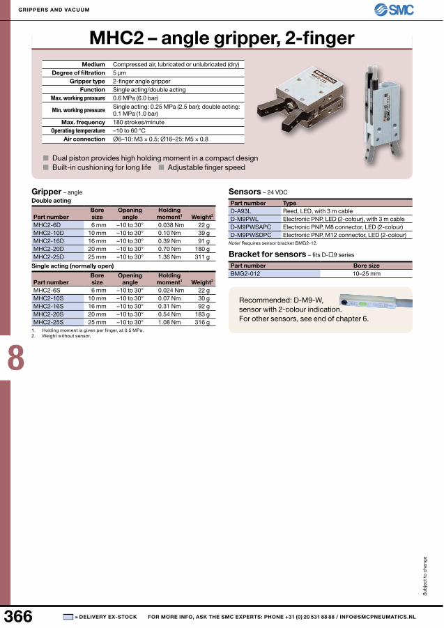
MHC2-6D 6 mm 0.038 nm 22 gMHC2-10D 10 mm 0.10 nm 39 gMHC2-16D 16 mm 0.39 nm 91 gMHC2-20D 20 mm 0.70 nm 180 gMHC2-25D 25 mm 1.36 nm 311 g
MHC2-6S 6 mm 0.024 nm 22 gMHC2-10S 10 mm 0.07 nm 30 gMHC2-16S 16 mm 0.31 nm 92 gMHC2-20S 20 mm 0.54 nm 183 gMHC2-25S 25 mm 1.08 nm 316 g
D-A93LD-M9PWLD-M9PWSAPCD-M9PWSDPC
BMG2-012 10–25 mm
Sub
ject
to
cha
nge
GrIPPErS AnD VACuuM
= DElIVEry EX-STOCK FOr MOrE InFO, ASK ThE SMC EXPErTS: PhOnE +31 (0) 20 531 88 88 / [email protected]
MhC2 – angle gripper, 2-finger Medium Compressed air, lubricated or unlubricated (dry)
Degree of filtrationGripper type 2-finger angle gripper
Function Single acting/double actingMax. working pressure
Min. working pressure Single acting: 0.25 MPa (2.5 bar); double acting: 0.1 MPa (1.0 bar)
Max. frequency 180 strokes/minuteOperating temperature –10 to 60 °C
Air connection
■ Dual piston provides high holding moment in a compact design■ Built-in cushioning for long life ■ Adjustable finger speed
Gripper – angleDouble acting
Part number Bore size
Opening angle
holding moment1 Weight2
–10 to 30°–10 to 30°–10 to 30°–10 to 30°–10 to 30°
Single acting (normally open)
Part number Bore size
Opening angle
holding moment1 Weight2
–10 to 30°–10 to 30°–10 to 30°–10 to 30°–10 to 30°
1. Holding moment is given per finger, at 0.5 MPa.2. Weight without sensor.
Sensors – 24 VDC
Part number TypeReed, LED, with 3 m cableElectronic PnP, LED (2-colour), with 3 m cableElectronic PnP, M8 connector, LED (2-colour)Electronic PnP, M12 connector, LED (2-colour)
Note! Requires sensor bracket BMG2-12.
Bracket for sensors – fits D-9 series
Part number Bore size
Recommended: D-M9-W, sensor with 2-colour indication. For other sensors, see end of chapter 6.
8
367■
5 µm
0.6 MPa (6.0 bar)0.4 MPa (4.0 bar)
0.017 nm
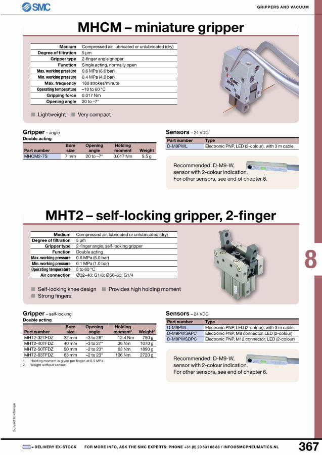
MHCM2-7S 7 mm 0.017 nm 9.5 g
D-M9PWL
5 µm
0.6 MPa (6.0 bar)0.1 MPa (1.0 bar)
Ø32–40: G1/8; Ø50–63: G1/4
MHT2-32TFDZ 32 mm 12.4 nm 790 gMHT2-40TFDZ 40 mm 36 nm 1070 gMHT2-50TFDZ 50 mm 63 nm 1890 gMHT2-63TFDZ 63 mm 106 nm 2720 g
D-M9PWLD-M9PWSAPCD-M9PWSDPC
Sub
ject
to
cha
nge
GrIPPErS AnD VACuuM
= DElIVEry EX-STOCK FOr MOrE InFO, ASK ThE SMC EXPErTS: PhOnE +31 (0) 20 531 88 88 / [email protected]
MhCM – miniature gripper Medium Compressed air, lubricated or unlubricated (dry)
Degree of filtrationGripper type 2-finger angle gripper
Function Single acting, normally openMax. working pressure Min. working pressure
Max. frequency 180 strokes/minuteOperating temperature –10 to 60 °C
Gripping forceOpening angle 20 to –7°
■ Lightweight ■ Very compact
Gripper – angleDouble acting
Part numberBore size
Opening angle
holding moment Weight
20 to –7°
Sensors – 24 VDC
Part number TypeElectronic PnP, LED (2-colour), with 3 m cable
MhT2 – self-locking gripper, 2-fingerMedium Compressed air, lubricated or unlubricated (dry)
Degree of filtrationGripper type 2-finger angle, self-locking gripper
Function Double actingMax. working pressure Min. working pressure Operating temperature 5 to 60 °C
Air connection
■ Self-locking knee design ■ Provides high holding moment■ Strong fingers
Gripper – self-lockingDouble acting
Part number Bore size
Opening angle
holding moment1 Weight2
–3 to 28°–3 to 27°–2 to 23°–2 to 23°
1. Holding moment is given per finger, at 0.5 MPa.2. Weight without sensor.
Sensors – 24 VDC
Part number TypeElectronic PnP, LED (2-colour), with 3 m cableElectronic PnP, M8 connector, LED (2-colour)Electronic PnP, M12 connector, LED (2-colour)
Recommended: D-M9-W, sensor with 2-colour indication. For other sensors, see end of chapter 6.
Recommended: D-M9-W, sensor with 2-colour indication. For other sensors, see end of chapter 6.
8
368 ■
5 µm
0.6 MPa (6.0 bar)0.1 MPa (1.0 bar)
M5 × 0.8
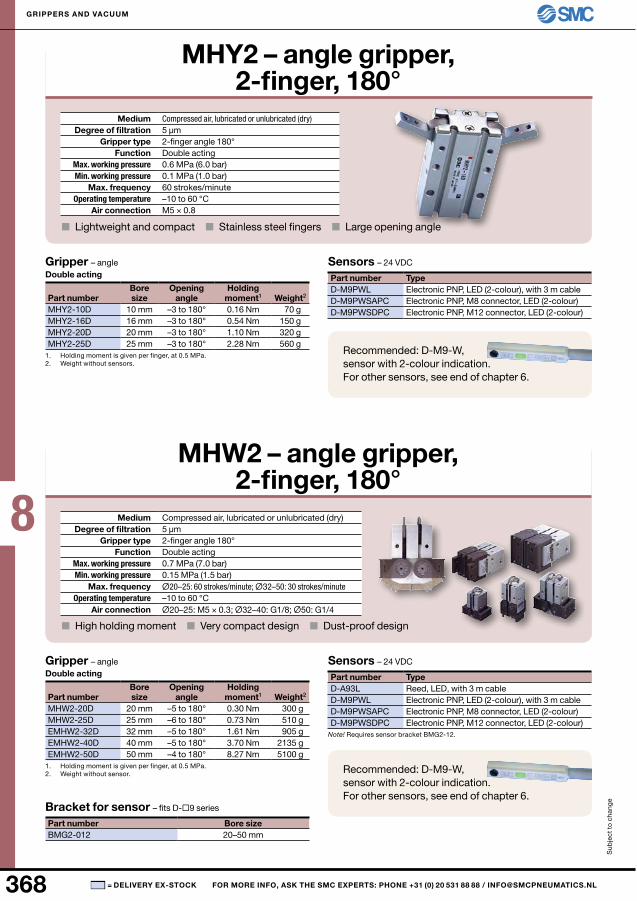
MHY2-10D 10 mm 0.16 nm 70 gMHY2-16D 16 mm 0.54 nm 150 gMHY2-20D 20 mm 1.10 nm 320 gMHY2-25D 25 mm 2.28 nm 560 g
D-M9PWLD-M9PWSAPCD-M9PWSDPC
5 µm
0.7 MPa (7.0 bar)0.15 MPa (1.5 bar)
Ø20–25: M5 × 0.3; Ø32–40: G1/8; Ø50: G1/4
MHW2-20D 20 mm 0.30 nm 300 gMHW2-25D 25 mm 0.73 nm 510 gEMHW2-32D 32 mm 1.61 nm 905 gEMHW2-40D 40 mm 3.70 nm 2135 gEMHW2-50D 50 mm 8.27 nm 5100 g
D-A93LD-M9PWLD-M9PWSAPCD-M9PWSDPC
BMG2-012 20–50 mm
Sub
ject
to
cha
nge
GrIPPErS AnD VACuuM
= DElIVEry EX-STOCK FOr MOrE InFO, ASK ThE SMC EXPErTS: PhOnE +31 (0) 20 531 88 88 / [email protected]
Mhy2 – angle gripper, 2-finger, 180°
Medium Compressed air, lubricated or unlubricated (dry)Degree of filtration
Gripper type 2-finger angle 180°Function Double acting
Max. working pressureMin. working pressure
Max. frequency 60 strokes/minuteOperating temperature –10 to 60 °C
Air connection
■ Lightweight and compact ■ Stainless steel fingers ■ Large opening angle
Gripper – angleDouble acting
Part numberBore size
Opening angle
holding moment1 Weight2
–3 to 180°–3 to 180°–3 to 180°–3 to 180°
1. Holding moment is given per finger, at 0.5 MPa.2. Weight without sensors.
Sensors – 24 VDC
Part number TypeElectronic PnP, LED (2-colour), with 3 m cableElectronic PnP, M8 connector, LED (2-colour)Electronic PnP, M12 connector, LED (2-colour)
MhW2 – angle gripper, 2-finger, 180°
Medium Compressed air, lubricated or unlubricated (dry)Degree of filtration
Gripper type 2-finger angle 180°Function Double acting
Max. working pressureMin. working pressure
Max. frequency Ø20–25: 60 strokes/minute; Ø32–50: 30 strokes/minuteOperating temperature –10 to 60 °C
Air connection
■ High holding moment ■ Very compact design ■ Dust-proof design
Gripper – angleDouble acting
Part numberBore size
Opening angle
holding moment1 Weight2
–5 to 180°–6 to 180°–5 to 180°–5 to 180°–4 to 180°
1. Holding moment is given per finger, at 0.5 MPa.2. Weight without sensor.
Sensors – 24 VDC
Part number TypeReed, LED, with 3 m cableElectronic PnP, LED (2-colour), with 3 m cableElectronic PnP, M8 connector, LED (2-colour)Electronic PnP, M12 connector, LED (2-colour)
Note! Requires sensor bracket BMG2-12.
Bracket for sensor – fits D-9 series
Part number Bore size
Recommended: D-M9-W, sensor with 2-colour indication. For other sensors, see end of chapter 6.
Recommended: D-M9-W, sensor with 2-colour indication. For other sensors, see end of chapter 6.
8
369■
5 µm
0.07–0.3 s/90°
M5 × 0.8
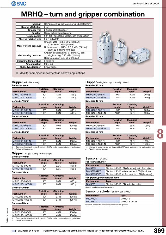
MRHQ10D-90S-n 90° 12 n 306 gMRHQ10D-180S-n 180° 12 n 305 g
MRHQ16D-90S-n 90° 36 n 598 gMRHQ16D-180S-n 180° 36 n 596 g
MRHQ20D-90S-n 90° 40 n 1055 gMRHQ20D-180S-n 180° 40 n 1052 g
MRHQ25D-90S-n 90° 65 n 1561 gMRHQ25D-180S-n 180° 65 n 1555 g
MRHQ10S-90S-n 90° 8.2 n 307 gMRHQ10S-180S-n 180° 8.2 n 306 g
MRHQ16S-90S-n 90° 28 n 600 gMRHQ16S-180S-n 180° 28 n 598 g
MRHQ20S-90S-n 90° 27 n 1060 gMRHQ20S-180S-n 180° 27 n 1057 g
MRHQ25S-90S-n 90° 43 n 1566 gMRHQ25S-180S-n 180° 43 n 1560 g
MRHQ10C-90S-n 90° 8.2 n 307 gMRHQ10C-180S-n 180° 8.2 n 306 g
MRHQ16C-90S-n 90° 27 n 600 gMRHQ16C-180S-n 180° 27 n 598 g
MRHQ20C-90S-n 90° 55 n 1060 gMRHQ20C-180S-n 180° 55 n 1057 g
MRHQ25C-90S-n 90° 82 n 1566 gMRHQ25C-180S-n 180° 82 n 1560 g
D-M9PWLD-M9PWSAPCD-M9PWSDPC
D-M9PVL
P407090-1 MRHQ10P407060-1 MRHQ16, 20, 25
Sub
ject
to
cha
nge
GrIPPErS AnD VACuuM
= DElIVEry EX-STOCK FOr MOrE InFO, ASK ThE SMC EXPErTS: PhOnE +31 (0) 20 531 88 88 / [email protected]
MrhQ – turn and gripper combinationMedium Compressed air, lubricated or unlubricated (dry)
Degree of filtrationGripper type 2-finger parallel gripper
Function Single acting/double actingrotation angle 90°, 180° adjustable ±50 in each end position
Allowed rotation time
Max. working pressure
Gripper: Ø10–16: 0.6 MPa (6.0 bar); Ø20–25: 0.7 MPa (7.0 bar)
Rotary actuator: Ø10–16: 0.7 MPa (7.0 bar); Ø20–25 1.0 MPa (10.0 bar)
Min. working pressure Gripper: double acting: 0.1 MPa (1.0 bar);
single acting: 0.25 MPa (2.5 bar)Rotary actuator: 0.25 MPa (2.5 bar)
Operating temperature 5 to 60 °CAir connection
Guide type (gripper) Linear guide
■ Ideal for combined movements in narrow applications
Gripper – double actingBore size 10 mm
Part number rotation
angleClamping
force1 Weight2
Bore size 16 mm
Part number rotation
angleClamping
force1 Weight2
Bore size 20 mm
Part number rotation
angleClamping
force1 Weight2
Bore size 25 mm
Part number rotation
angleClamping
force1 Weight2
1. Clamping force is given per finger, at 0.5 MPa and an assumed gripping distance.2. Weight without sensor.
Gripper – single acting, normally open Bore size 10 mm
Part number rotation
angleClamping
force1 Weight2
Bore size 16 mm
Part number rotation
angleClamping
force1 Weight2
Bore size 20 mm
Part number rotation
angleClamping
force1 Weight2
Bore size 25 mm
Part number rotation
angleClamping
force1 Weight2
1. Clamping force is given per finger, at 0.5 MPa and an assumed gripping distance.2. Weight without sensor.
Gripper – single acting, normally closedBore size 10 mm
Part number rotation
angleClamping
force1 Weight2
Bore size 16 mm
Part number rotation
angleClamping
force1 Weight2
Bore size 20 mm
Part number rotation
angleClamping
force1 Weight2
Bore size 25 mm
Part number rotation
angleClamping
force1 Weight2
1. Clamping force is given per finger, at 0.5 MPa and an assumed gripping distance.2. Weight without sensor.
Sensors – 24 VDC For rotary actuator
Part number TypeElectronic PnP, LED (2-colour), with 3 m cableElectronic PnP, M8 connector, LED (2-colour)Electronic PnP, M12 connector, LED (2-colour)
For gripper, perpendicular cable
Part number TypeElectronic PnP, LED, with 3 m cable
Sensor bracket ordered separately.
Sensor brackets – one set per MRHQ
Part number Type
Includes holders for both rotary actuator and gripper.
8
370 ■
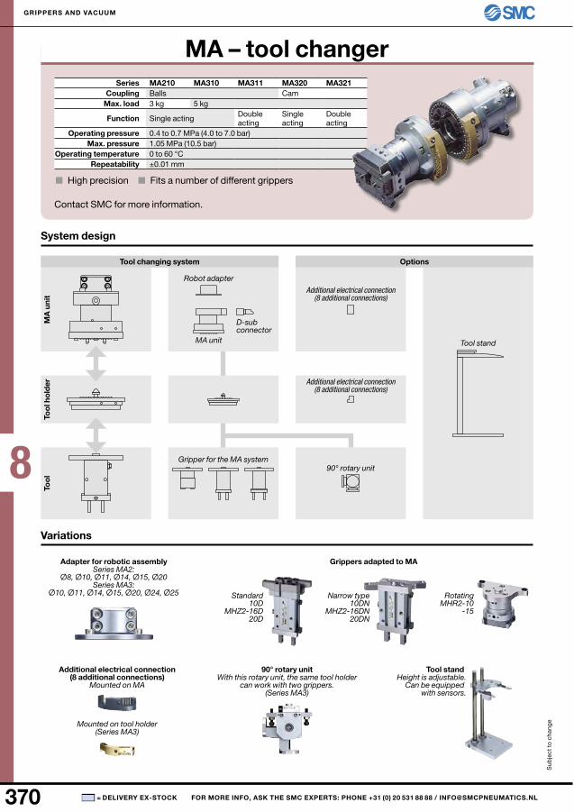
MA210 MA310 MA311 MA320 MA321
3 kg 5 kg
1.05 MPa (10.5 bar)
±0.01 mm
Ø8, Ø10, Ø11, Ø14, Ø15, Ø20
Ø10, Ø11, Ø14, Ø15, Ø20, Ø24, Ø2510D
MHZ2-16D20D
10DNMHZ2-16DN
20DN
MHR2-10-15
Sub
ject
to
cha
nge
GrIPPErS AnD VACuuM
= DElIVEry EX-STOCK FOr MOrE InFO, ASK ThE SMC EXPErTS: PhOnE +31 (0) 20 531 88 88 / [email protected]
MA – tool changerSeries
Coupling Balls CamMax. load
Function Single acting Double acting
Single acting
Double acting
Operating pressure 0.4 to 0.7 MPa (4.0 to 7.0 bar)Max. pressure
Operating temperature 0 to 60 °Crepeatability
■ High precision ■ Fits a number of different grippers
System design
Variations
Tool changing system Options
D-sub connector
MA unit
Robot adapter
MA
uni
tTo
ol h
old
erTo
ol
Gripper for the MA system
Additional electrical connection (8 additional connections)
Additional electrical connection (8 additional connections)
90° rotary unit
Tool stand
Adapter for robotic assemblySeries MA2:
Series MA3:
Grippers adapted to MA
Additional electrical connection (8 additional connections)
Mounted on MA
Mounted on tool holder(Series MA3)
Tool standHeight is adjustable.
Can be equipped with sensors.
90° rotary unitWith this rotary unit, the same tool holder
can work with two grippers.(Series MA3)
Standard Narrow type Rotating
Contact SMC for more information.
8
371■
20 mm 40 mm 60 mm 80 mm 100 mmM5 × 0.8 Rc1/8"
0.01–0.5 MPa (0.1–5 bar)0.75 MPa (7.5 bar)0.4 MPa (4 bar)
3 n 11 n 19 n 27 n 35 n
XT661-2A-R20 mm
XT661-2A-LXT661-4A-R
40 mmXT661-4A-LXT661-6A-R
60 mmXT661-6A-L
1.05 MPa (10.5 bar)
±0.015 mm
XT661-8A-R80 mm
XT661-8A-LXT661-10A-R
100 mmXT661-10A-L
nBR0.7 MPa
■
ZH-DBM0078 2700 l/min 1980 l/min 720 l/minSub
ject
to
cha
nge
GrIPPErS AnD VACuuM
= DElIVEry EX-STOCK FOr MOrE InFO, ASK ThE SMC EXPErTS: PhOnE +31 (0) 20 531 88 88 / [email protected]
XT661 – non-contact gripperOutside diameter
ConnectionMedium Air
Working pressure Max. pressure
Optimum supply pressureOperating temperature –5 to 60 °C
lift force at 0.4 MPa
Cyclone technology makes the unit suitable for:■ uneven surfaces where ordinary pads are leaking■ Sensitive surfaces that can be sucked-in or is influenced by touching■ Applications that quickly wears out usual vacuum pads
non-contact gripperPart number rotation direction Outside diam.
RightLeft
RightLeft
RightLeft
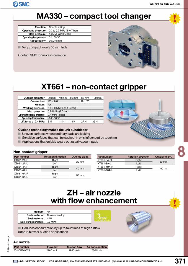
MA330 – compact tool changerFunction Double acting
Operating pressure 0.3 to 0.7 MPa (3 to 7 bar)Max. pressure
Operating temperature 0 to 60 °Crepeatability
■ Very compact – only 50 mm high
Contact SMC for more information.
Part number rotation direction Outside diam.RightLeft
RightLeft
Zh – air nozzle with flow enhancement
Medium AirBody material Aluminium alloySeal material
Max. working pressure
■ Reduces consumption by up to four times at high airflow rates in blow or suction applications
Air nozzlePart number Flow out Suction flow Air consumption
8
372 ■
nBr● ● ● ●● ● ● ●● ● ● ●● ● ● ●● ● ● ●● ● ● ●● ● ● ●● ● ● ●● ● ● ●● ● ● ●● ● ● ●● ● ● ●● ● ● ●
● ●
●
ZP02un 2 mmZP04un 4 mmZP06un 6 mmZP06Bn 6 mmZP08un 8 mmZP08Bn 8 mmZP10un 10 mmZP10Cn 10 mmZP10Dn 10 mmZP10Bn 10 mmZP16un 16 mmZP16Cn 16 mmZP16Dn 16 mmZP16Bn 16 mmZP20un 20 mmZP20Bn 20 mmZP25un 25 mmZP25Cn 25 mmZP25Dn 25 mmZP25Bn 25 mmZP32un 32 mmZP32Bn 32 mmZP40un 40 mmZP40Cn 40 mmZP40Dn 40 mmZP40Bn 40 mmZP50un 50 mmZP50Bn 50 mm
Sub
ject
to
cha
nge
GrIPPErS AnD VACuuM
= DElIVEry EX-STOCK FOr MOrE InFO, ASK ThE SMC EXPErTS: PhOnE +31 (0) 20 531 88 88 / [email protected]
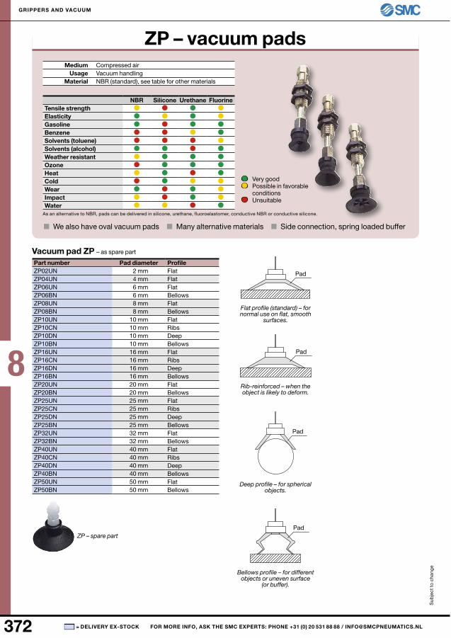
ZP – vacuum padsMedium Compressed air
usage Vacuum handlingMaterial nBR (standard), see table for other materials
Silicone urethane FluorineTensile strengthElasticityGasolineBenzeneSolvents (toluene)Solvents (alcohol)Weather resistantOzoneheatColdWearImpactWater
As an alternative to nBR, pads can be delivered in silicone, urethane, fluoroelastomer, conductive nBR or conductive silicone.
■ We also have oval vacuum pads ■ Many alternative materials ■ Side connection, spring loaded buffer
Very good Possible in favorable
conditions unsuitable
Vacuum pad ZP – as spare part
Part number Pad diameter ProfileFlatFlatFlatBellowsFlatBellowsFlatRibsDeepBellowsFlatRibsDeepBellowsFlatBellowsFlatRibsDeepBellowsFlatBellowsFlatRibsDeepBellowsFlatBellows
ZP – spare part
Flat profile (standard) – for normal use on flat, smooth
surfaces.
Bellows profile – for different objects or uneven surface
(or buffer).
Deep profile – for spherical objects.
Rib-reinforced – when the object is likely to deform.
Pad
Pad
Pad
Pad
8
373■
2–8 mm ZPT1-A5ZPT1-A6
ZPT1-B5ZPT1-B6
ZPRS-04-A5ZPRS-04-A6ZPRS-04-B4ZPRS-04-B5
ZPRS-06-A5ZPRS-06-A6ZPRS-06-B4ZPRS-06-B5
—
10–16 mm ZPT2-A5ZPT2-A6
ZPT2-B5ZPT2-B6ZPT2-B01
ZPRS-04-A5ZPRS-04-A6ZPRS-04-B5ZPRS-04-B6
ZPRS-06-A5ZPRS-06-A6ZPRS-06-B5ZPRS-06-B6
20–32 mm ZPT3-A6ZPT3-A8
ZPT3-B5ZPT3-B6ZPT3-B8ZPT3-B01
ZPRL-04-A6ZPRL-04-A8ZPRL-04-B5ZPRL-04-B6ZPRL-04-B8
ZPRL-06-A6ZPRL-06-A8ZPRL-06-B5ZPRL-06-B6ZPRL-06-B8
ZPRL-08-A6ZPRL-08-A8ZPRL-08-B5ZPRL-08-B6ZPRL-08-B8
40–50 mm ZPT4-A6ZPT4-A8
ZPT4-B6ZPT4-B8ZPT4-B01
—
ZPRL-06-A6ZPRL-06-A8ZPRL-06-B6ZPRL-06-B8
ZPRL-08-A6ZPRL-08-A8ZPRL-08-B6ZPRL-08-B8
6 mm ZPB1j6 ZPB1K6 ZPB1j6-B3ZPB1j6-B5
ZPB1K6-B3ZPB1K6-B5
10 mm ZPB2j10ZPB3j10
ZPB2K10ZPB3K10
ZPB1j10-B5ZPB2j10-B5ZPB3j10-B5ZPB3j10-B01
ZPB1K10-B5ZPB2K10-B5ZPB3K10-B5ZPB3K10-B01
20 mm ZPB3j20 ZPB3K20 ZPB3j20-B01 ZPB3K20-B01
Snj-010A 2–8 mmSnj-015A 10–32 mmSn-015A 40–50 mm
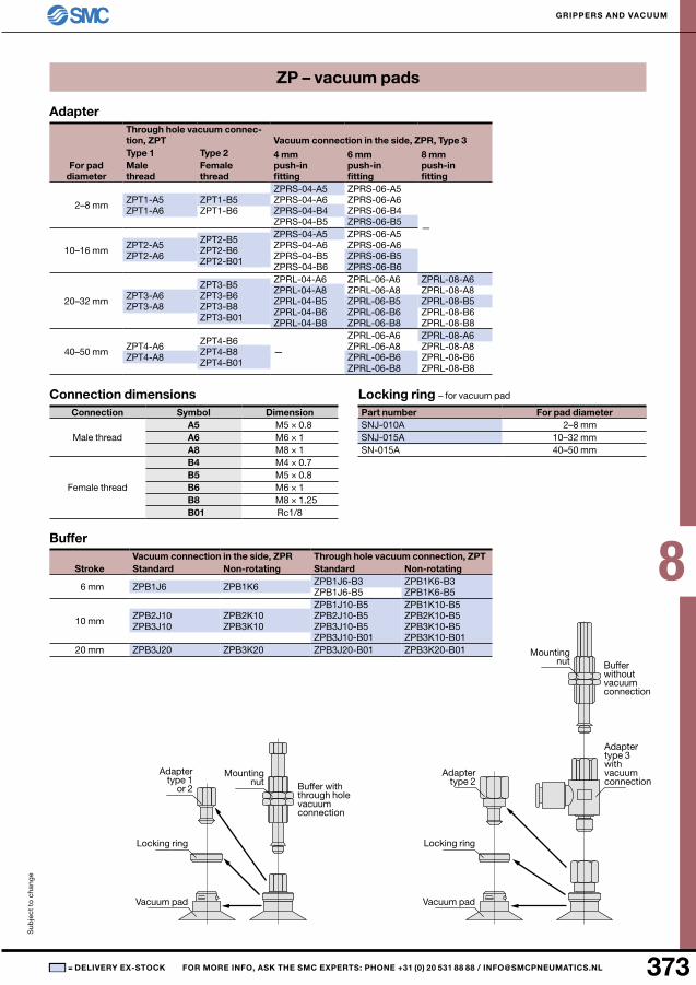
A5 M5 × 0.8A6 M6 × 1A8 M8 × 1B4 M4 × 0.7B5 M5 × 0.8B6 M6 × 1B8 M8 × 1.25
B01 Rc1/8
Sub
ject
to
cha
nge
GrIPPErS AnD VACuuM
= DElIVEry EX-STOCK FOr MOrE InFO, ASK ThE SMC EXPErTS: PhOnE +31 (0) 20 531 88 88 / [email protected]
Adapter
For pad diameter
Through hole vacuum connec-tion, ZPT Vacuum connection in the side, ZPr, Type 3Type 1 Type 2 4 mm
push-in fitting
6 mm push-in fitting
8 mm push-in fitting
Male thread
Female thread
ZP – vacuum pads
Buffer
StrokeVacuum connection in the side, ZPr Through hole vacuum connection, ZPTStandard non-rotating Standard non-rotating
locking ring – for vacuum pad
Part number For pad diameter
Connection dimensionsConnection Symbol Dimension
Male thread
Female thread
Adapter type 1
or 2 Buffer with through hole vacuum connection
Mounting nut
Locking ring
Vacuum pad
Adapter type 2
Adapter type 3 with vacuum connection
Buffer without vacuum connection
Mounting nut
Locking ring
Vacuum pad
8
374 ■
nBr● ● ● ●● ● ● ●● ● ● ●● ● ● ●● ● ● ●● ● ● ●● ● ● ●● ● ● ●● ● ● ●● ● ● ●● ● ● ●● ● ● ●● ● ● ●
40
Ø40–50 A14Ø63–125 A16
Ø40–80B8
B10
Ø63–125B12B16
- A14ZPT
hhB
h
40 40 mm 50 50 mm 63 63 mm 80 80 mm100 100 mm125 125 mm
n
n nBRSuF
● ●
●
Sub
ject
to
cha
nge
GrIPPErS AnD VACuuM
= DElIVEry EX-STOCK FOr MOrE InFO, ASK ThE SMC EXPErTS: PhOnE +31 (0) 20 531 88 88 / [email protected]
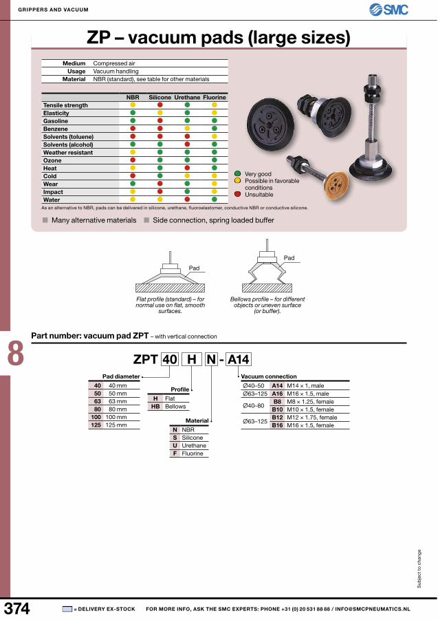
ZP – vacuum pads (large sizes)Medium Compressed air
usage Vacuum handlingMaterial nBR (standard), see table for other materials
Silicone urethane FluorineTensile strengthElasticityGasolineBenzeneSolvents (toluene)Solvents (alcohol)Weather resistantOzoneheatColdWearImpactWater
As an alternative to nBR, pads can be delivered in silicone, urethane, fluoroelastomer, conductive nBR or conductive silicone.
■ Many alternative materials ■ Side connection, spring loaded buffer
Part number: vacuum pad ZPT – with vertical connection
Vacuum connection
M14 × 1, male M16 × 1.5, male
M8 × 1.25, femaleM10 × 1.5, female
M12 × 1.75, femaleM16 × 1.5, female
Profile
FlatBellows
Pad diameter
Material
SiliconeurethaneFluorine
Flat profile (standard) – for normal use on flat, smooth
surfaces.
Bellows profile – for different objects or uneven surface
(or buffer).
Pad
Pad
Very good Possible in favorable
conditions unsuitable
8
375■
40
Ø40–50 B8Ø63–125 B10Ø40–80 B12
- B10ZPX
hhB
h
40 40 mm 50 50 mm 63 63 mm 80 80 mm100 100 mm125 125 mm
n
n nBRSuF
B01 -
B01 Rc1/8
40
Ø40–80 A18Ø100–125 A22
- A18ZPX
hhB
h
40 40 mm 50 50 mm 63 63 mm 80 80 mm100 100 mm125 125 mm
n
n nBRSuF
J 25 B01 -
Ø40–125 25 25 mm 50 50 mm 75 75 mm
Ø100–125 100 100 mm
B01 Rc1/8
40
Ø40–80 A18Ø100–125 A22
- A18ZPT
hhB
h
40 40 mm 50 50 mm 63 63 mm 80 80 mm100 100 mm125 125 mm
n
n nBRSuF
J 25 B01 -
Ø40–125 25 25 mm 50 50 mm 75 75 mm
Ø100–125 100 100 mm
B01 Rc1/8
Sub
ject
to
cha
nge
GrIPPErS AnD VACuuM
= DElIVEry EX-STOCK FOr MOrE InFO, ASK ThE SMC EXPErTS: PhOnE +31 (0) 20 531 88 88 / [email protected]
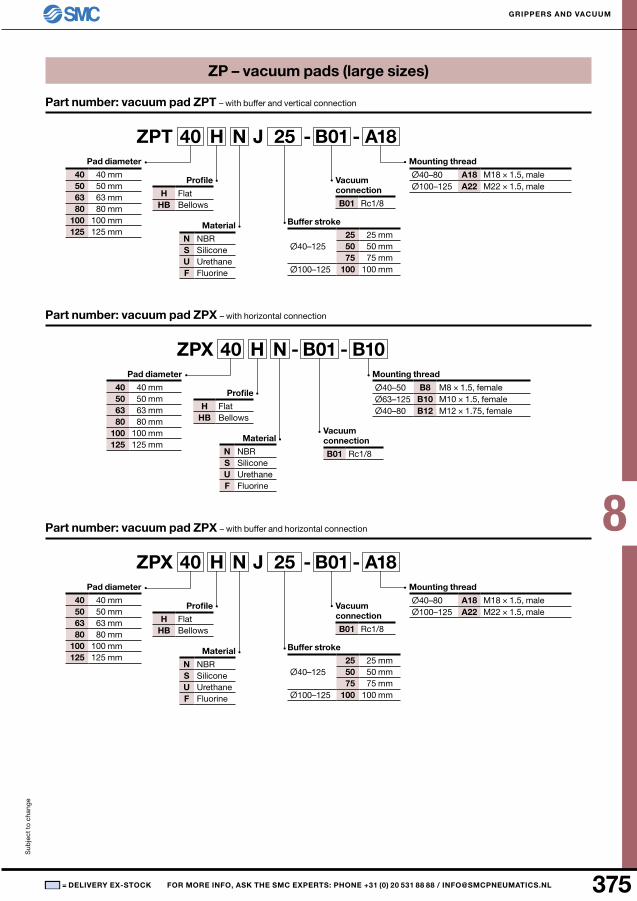
ZP – vacuum pads (large sizes)
Part number: vacuum pad ZPX – with horizontal connection
Mounting thread
M8 × 1.5, female M10 × 1.5, female M12 × 1.75, female
Profile
FlatBellows
Pad diameter
Material
SiliconeurethaneFluorine
Vacuum connection
Part number: vacuum pad ZPX – with buffer and horizontal connection
Mounting thread
M18 × 1.5, male M22 × 1.5, male
Profile
FlatBellows
Pad diameter
Material
SiliconeurethaneFluorine
Buffer stroke
Vacuum connection
Part number: vacuum pad ZPT – with buffer and vertical connection
Mounting thread
M18 × 1.5, male M22 × 1.5, male
Profile
FlatBellows
Pad diameter
Material
SiliconeurethaneFluorine
Buffer stroke
Vacuum connection
8
376 ■
AMj3000-F03 G3/8AMj4000-F04 G1/2AMj5000-F10 G1
AMJ3000 AMJ4000 AMJ5000
G1/4 G1/2 G11.0 MPa (10 bar)–0.1 MPa (–1 bar)1.5 MPa (15 bar)
200 ln/min 300 ln/min 500 ln/min
0.3 kg 0.6 kg 1.1 kg
B340AB440AB640A
AMj-EL3000 3000AMj-EL4000 4000AMj-EL5000 5000
ZFA ZFB ZFC
0.5 MPa (5 bar)
30 µm 10 µm 10 µm
ZFA100-F01 G1/8 100 ln/minZFA200-F02 G1/8 200 ln/min
ZFB100-04 4 mm 10 ln/minZFB100-06 6 mm 20 ln/minZFB200-06 6 mm 30 ln/minZFB200-08 8 mm 50 ln/minZFB300-08 8 mm 75 ln/minZFB300-10 10 mm 75 ln/min
ZFC050-02B 2 mm 2 ln/minZFC050-04B 4 mm 10 ln/minZFC100-04B 4 mm 10 ln/minZFC100-06B 6 mm 20 ln/minZFC200-06B 6 mm 30 ln/minZFC200-08B 8 mm 50 ln/min
Ej001H-030n ZFA100Ej101H-030n ZFA200I-34S-A ZFB100I-35S-A ZFB200I-36S-A ZFB300 I-68S-A ZFC050I-62S-A ZFC100I-63S-A ZFC200
ZFA
ZFB
ZFC
Sub
ject
to
cha
nge
GrIPPErS AnD VACuuM
= DElIVEry EX-STOCK FOr MOrE InFO, ASK ThE SMC EXPErTS: PhOnE +31 (0) 20 531 88 88 / [email protected]
Water separatorPart number Connection
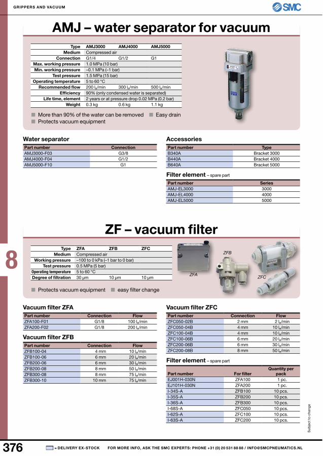
AMJ – water separator for vacuum Type
Medium Compressed airConnection
Max. working pressure Min. working pressure
Test pressureOperating temperature 5 to 60 °C
recommended flow Efficiency 90% (only condensed water is separated)
life time, element 2 years or at pressure drop 0.02 MPa (0.2 bar)Weight
■ More than 90% of the water can be removed ■ Easy drain■ Protects vacuum equipment
AccessoriesPart number Type
Bracket 3000Bracket 4000Bracket 5000
Filter element – spare part
Part number Series
ZF – vacuum filterType
Medium Compressed airWorking pressure –100 to 0 kPa (–1 bar to 0 bar)
Test pressureOperating temperature 5 to 60 °CDegree of filtration
■ Protects vacuum equipment ■ easy filter change
Vacuum filter ZFAPart number Connection Flow
Vacuum filter ZFBPart number Connection Flow
Vacuum filter ZFCPart number Connection Flow
Filter element – spare part
Part number For filter Quantity per
pack 1 pc. 1 pc.10 pcs.10 pcs.10 pcs.10 pcs.10 pcs.10 pcs.
8
377■
M5 M8, R1/8, G1/80.3 mm 0.5 mm 0.7 mm 0.5 mm 0.7 mm 1 mm
40 µm3 ln/min 5 ln/min 8 ln/min 5 ln/min 8 ln/min 16 ln/min
ZP2V-A5-03 M5 3 ln/minZP2V-A5-05 M5 5 ln/minZP2V-A5-07 M5 7 ln/minZP2V-A8-05 M8 5 ln/minZP2V-A8-07 M8 7 ln/minZP2V-A8-10 M8 10 ln/minZP2V-AG1-05 G1/8" 5 ln/minZP2V-AG1-07 G1/8" 7 ln/minZP2V-AG1-10 G1/8" 10 ln/minZP2V-A01-05 R1/8" 5 ln/minZP2V-A01-07 R1/8" 7 ln/minZP2V-A01-10 R1/8" 10 ln/min
ZP2V-B5-03 M5 3 ln/minZP2V-B5-05 M5 5 ln/minZP2V-B5-07 M5 7 ln/minZP2V-BG1-05 G1/8" 5 ln/minZP2V-BG1-07 G1/8" 7 ln/minZP2V-BG1-10 G1/8" 10 ln/minZP2V-B01-05 R1/8" 5 ln/minZP2V-B01-07 R1/8" 7 ln/minZP2V-B01-10 R1/8" 10 ln/min
Sub
ject
to
cha
nge
GrIPPErS AnD VACuuM
= DElIVEry EX-STOCK FOr MOrE InFO, ASK ThE SMC EXPErTS: PhOnE +31 (0) 20 531 88 88 / [email protected]
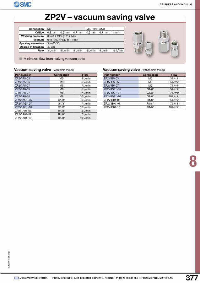
ZP2V – vacuum saving valveConnection
OrificeWorking pressure 0 to 0.7 MPa (0 to 7 bar)
Vacuum 0 to –100 kPa (0 to –1 bar)Operating temperature 5 to 60 °CDegree of filtration
Flow
■ Minimizes flow from leaking vacuum pads
Vacuum saving valve – with male thread
Part number Connection Flow
Vacuum saving valve – with female thread
Part number Connection Flow
8
378 ■
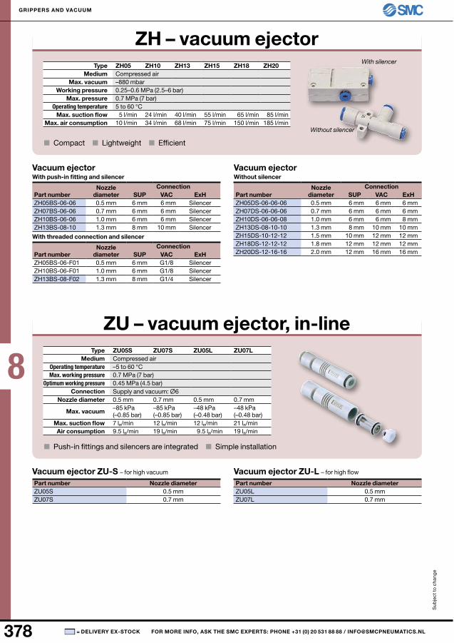
Zh05 Zh10 Zh13 Zh15 Zh18 Zh20
–880 mbar0.25–0.6 MPa (2.5–6 bar)0.7 MPa (7 bar)
5 l/min 24 l/min 40 l/min 55 l/min 65 l/min 85 l/min10 l/min 34 l/min 68 l/min 75 l/min 150 l/min 185 l/min
Zu05S Zu07S Zu05l Zu07l
0.7 MPa (7 bar)0.45 MPa (4.5 bar) 0.5 mm 0.7 mm 0.5 mm 0.7 mm–85 kPa (–0.85 bar)
–85 kPa (–0.85 bar)
–48 kPa (–0.48 bar)
–48 kPa (–0.48 bar)
7 ln/min 12 ln/min 12 ln/min 21 ln/min9.5 ln/min 19 ln/min 9.5 ln/min 19 ln/min
Zu05S 0.5 mmZu07S 0.7 mm
Zu05L 0.5 mmZu07L 0.7 mm
SuP VAC ExhZH05BS-06-06 0.5 mm 6 mm 6 mmZH07BS-06-06 0.7 mm 6 mm 6 mmZH10BS-06-06 1.0 mm 6 mm 6 mmZH13BS-08-10 1.3 mm 8 mm 10 mm
SuP VAC ExhZH05BS-06-F01 0.5 mm 6 mm G1/8ZH10BS-06-F01 1.0 mm 6 mm G1/8ZH13BS-08-F02 1.3 mm 8 mm G1/4
SuP VAC ExhZH05DS-06-06-06 0.5 mm 6 mm 6 mm 6 mmZH07DS-06-06-06 0.7 mm 6 mm 6 mm 6 mmZH10DS-06-06-08 1.0 mm 6 mm 6 mm 8 mmZH13DS-08-10-10 1.3 mm 8 mm 10 mm 10 mmZH15DS-10-12-12 1.5 mm 10 mm 12 mm 12 mmZH18DS-12-12-12 1.8 mm 12 mm 12 mm 12 mmZH20DS-12-16-16 2.0 mm 12 mm 16 mm 16 mm
Sub
ject
to
cha
nge
GrIPPErS AnD VACuuM
= DElIVEry EX-STOCK FOr MOrE InFO, ASK ThE SMC EXPErTS: PhOnE +31 (0) 20 531 88 88 / [email protected]
Zh – vacuum ejector Type
Medium Compressed airMax. vacuum
Working pressure Max. pressure
Operating temperature 5 to 60 °CMax. suction flow
Max. air consumption
■ Compact ■ Lightweight ■ Efficient
Zu – vacuum ejector, in-lineType
Medium Compressed airOperating temperature –5 to 60 °CMax. working pressure
Optimum working pressureConnection Supply and vacuum: Ø6
nozzle diameter
Max. vacuum
Max. suction flowAir consumption
■ Push-in fittings and silencers are integrated ■ Simple installation
Vacuum ejector Zu-S – for high vacuum
Part number nozzle diameter
Vacuum ejector Zu-l – for high flow
Part number nozzle diameter
Vacuum ejectorWith push-in fitting and silencer
Part numbernozzle
diameterConnection
SilencerSilencerSilencerSilencer
With threaded connection and silencer
Part numbernozzle
diameterConnection
SilencerSilencerSilencer
With silencer
Without silencer
Vacuum ejectorWithout silencer
Part numbernozzle
diameterConnection
8
379■
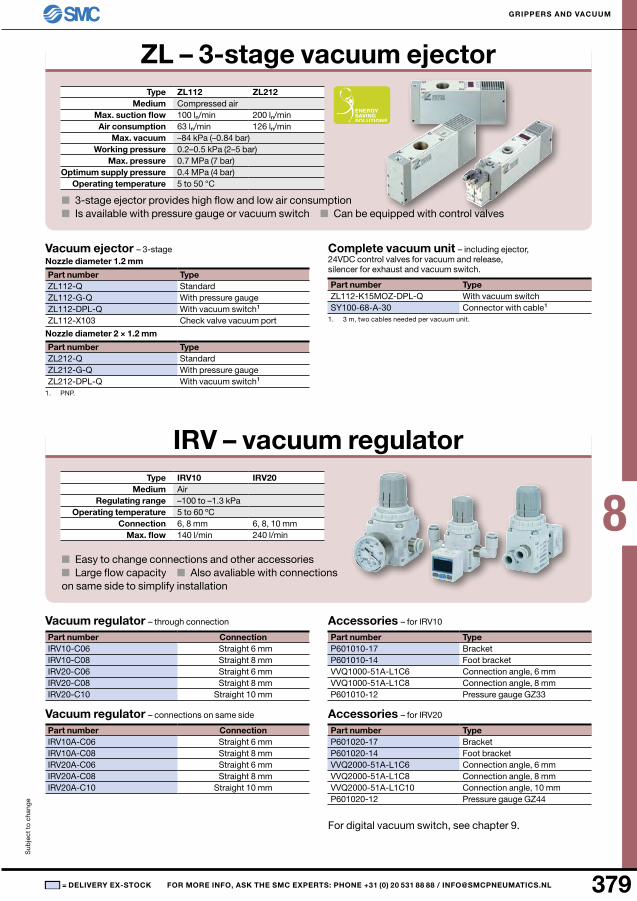
Zl112 Zl212
100 ln/min 200 ln/min63 ln/min 126 ln/min–84 kPa (–0.84 bar)0.2–0.5 kPa (2–5 bar)0.7 MPa (7 bar)0.4 MPa (4 bar)
ZL112-QZL112-G-QZL112-DPL-QZL112-X103
ZL212-QZL212-G-QZL212-DPL-Q
ZL112-K15MOZ-DPL-QSY100-68-A-30
IrV10 IrV20
6, 8 mm 6, 8, 10 mm140 l/min 240 l/min
IRV10-C06IRV10-C08IRV20-C06IRV20-C08IRV20-C10
IRV10A-C06IRV10A-C08IRV20A-C06IRV20A-C08IRV20A-C10
P601010-17P601010-14VVQ1000-51A-L1C6VVQ1000-51A-L1C8P601010-12
P601020-17P601020-14VVQ2000-51A-L1C6VVQ2000-51A-L1C8VVQ2000-51A-L1C10P601020-12
Sub
ject
to
cha
nge
GrIPPErS AnD VACuuM
= DElIVEry EX-STOCK FOr MOrE InFO, ASK ThE SMC EXPErTS: PhOnE +31 (0) 20 531 88 88 / [email protected]
Zl – 3-stage vacuum ejectorType
Medium Compressed airMax. suction flowAir consumption
Max. vacuum Working pressure
Max. pressureOptimum supply pressure
Operating temperature 5 to 50 °C
■ 3-stage ejector provides high flow and low air consumption■ Is available with pressure gauge or vacuum switch ■ Can be equipped with control valves
Vacuum ejector – 3-stagenozzle diameter 1.2 mm
Part number TypeStandardWith pressure gaugeWith vacuum switch 1
Check valve vacuum port
nozzle diameter 2 × 1.2 mm
Part number TypeStandardWith pressure gaugeWith vacuum switch 1
1. PnP.
Complete vacuum unit – including ejector, 24VDC control valves for vacuum and release, silencer for exhaust and vacuum switch.
Part number TypeWith vacuum switchConnector with cable 1
1. 3 m, two cables needed per vacuum unit.
IrV – vacuum regulatorType
Medium Airregulating range –100 to –1.3 kPa
Operating temperature 5 to 60 ºCConnection
Max. flow
■ Easy to change connections and other accessories■ Large flow capacity ■ Also avaliable with connections on same side to simplify installation
Vacuum regulator – through connection
Part number Connection Straight 6 mm Straight 8 mm Straight 6 mm Straight 8 mmStraight 10 mm
Vacuum regulator – connections on same side
Part number Connection Straight 6 mm Straight 8 mm Straight 6 mm Straight 8 mmStraight 10 mm
Accessories – for IRV10
Part number TypeBracketFoot bracketConnection angle, 6 mmConnection angle, 8 mmPressure gauge GZ33
Accessories – for IRV20
Part number TypeBracketFoot bracketConnection angle, 6 mmConnection angle, 8 mmConnection angle, 10 mmPressure gauge GZ44
For digital vacuum switch, see chapter 9.

8
380 ■
–84 kPa (–0.84 bar)0.2–0.55 MPa (2–5.5 bar)0.7 MPa (7 bar)0.4 MPa (4 bar)
M512–24 VDC
ZX1101-K15LOZ-E55Cn-QSY100-30-4A-6 0.6 mSY100-30-4A-30 3.0 m
ZS-10-5A 0.6 mZS-10-5A-30 3.0 m
SY114-5LOu-QZX1-FE
40 l/min46 l/min–840 mbar0.2–0.55 MPa (2–5.5 bar)0.7 MPa (7 bar)0.4 MPa (4 bar)
G1/8
EZM131HF-K5LOZ-E55L-QZM-FCA-0ZM-SA-0ZM-SFZSE1-00-55LVj114-5LOZ-QSY100-68-A-6SY100-68-A-30
Sub
ject
to
cha
nge
GrIPPErS AnD VACuuM
= DElIVEry EX-STOCK FOr MOrE InFO, ASK ThE SMC EXPErTS: PhOnE +31 (0) 20 531 88 88 / [email protected]
ZX – vacuum unitMedium Compressed air, unlubricated, filtered 5 µm
Max. suction 22 l/min (10 l/min in manifold)Max. air consumption 46 l/min (23 l/min in manifold)
Max. vacuum Working pressure
Max. pressure Optimum supply pressure
Operating temperature 5 to 60 °CConnection
Supply voltage
■ Very compact, lightweight – ideal for robotic applications■ Includes all necessary components for complete vacuum control
Vacuum unit – individual assembly, including vacuum ejector, control valve, vacuum switch/filter
Part number
Vacuum unit – manifold assembly, contact SMC
Cable – to control valves
Part number Cable
Note! Two cables needed per vacuum unit.
Cable – to vacuum switch
Part number Cable
Spare partsPart number Type
Pilot valveSuction filter
ZM – 2-stage vacuum unitMedium Compressed air, unlubricated, filtered 5 µm
Max. suctionMax. air consumption
Max. vacuum Working pressure
Max. pressure Optimum supply pressure
Operating temperature 5 to 60 °CConnection
■ ZM – very compact ■ Also available in manifold assembly
Vacuum unit – individual assembly, including vacuum ejector, control valves, vacuum switch/filter
Part number
Vacuum unit – manifold assembly, contact SMC
Spare partsPart number Type
Filter lidSilencerSuction filterVacuum switchPilot valveCable 600 mmCable 3000 mm