grond - a 7-channel imager - max planck societyjcg/grond/grond_pasp.pdf · grond - a 7-channel...
TRANSCRIPT

GROND - a 7-channel imager
J. Greiner, W. Bornemann, C. Clemens, M. Deuter, G. Hasinger, M. Honsberg, H. Huber,
S. Huber, M. Krauss1 T. Kruhler, A. Kupcu Yoldas, H. Mayer-Hasselwander, B. Mican, N.
Primak, F. Schrey, I. Steiner2, G. Szokoly3, C.C. Thone4, A. YoldasMax-Planck-Institut fur extraterrestrische Physik, 85740 Garching, Germany
jcg, wab, cclemens, grh, hhuber, shuber, kruehler, ayoldas, H-M-H, b.mican, prima, fzs,
and
S. Klose, U. Laux, J. WinklerThuringer Landessternwarte, Sternwarte 5, 07778 Tautenburg, Germany
laux, klose, [email protected]
ABSTRACT
We describe the construction of GROND, a 7-channel imager, primarily designed for rapidobservations of gamma-ray burst afterglows. It allows simultaneous imaging in the Sloan g′r′i′z′
and near-infrared JHK bands. GROND was commissioned at the MPI/ESO 2.2m telescope atLa Silla (Chile) in April 2007, and first results of its performance and calibration are presented.
Subject headings: instrumentation: detectors, techniques: photometric
1. Introduction
Simultaneous imaging in different filter-bandsis of interest in a variety of astrophysical areas.The primary aim is to measure the spectral en-ergy distribution or its evolution in variable ob-jects in order to uncover the underlying emis-sion mechanism. Examples are, among others,(1) monitoring of all kinds of variable stars (flarestars, cataclysmic variables, X-ray binaries) to de-termine the outburst mechanisms and differenti-
1present address: ATV Technologie GmbH, D-85591Vaterstetten, Johann-Sebastian-Bach-Str. 38; email:[email protected]
2present address: Ruhr-Universitat Bochum, As-tronomisches Institut, Universitatsstr. 150, 44780 Bochum;email: [email protected]
3present address: Institute of Physics, Eotvos Univer-sity, Pazmany P. s. 1/A, 1117 Budapest, Hungary; [email protected]
4present address: Dark Cosmology Center, Niels BohrInstitute, Univ. of Copenhagen, Juliane Maries Vej 30,DK-2100 Kobenhavn; [email protected]
ate between physical state changes and changesinduced by geometrical variations, like eclipses;(2) monitoring of AGN to understand the phys-ical origin of the observed variability; (3) deter-mining the inclination of X-ray heated binaries(Orosz & Bailyn 1997) (4) mapping of galaxies tostudy the stellar population; (5) multi-color lightcurves of supernovae (Taubenberger et al. 2006);(6) differentiate achromatic microlensing events(Paczynski 1986) from other variables with sim-ilar light curves; (7) identifying objects with pe-culiar spectral energy distributions, e.g. photo-metric redshift surveys for high-z active galacticnuclei, or identifying brown dwarfs; (8) follow-up observations of transiting extrasolar planets(Jha et al. 2000); or (9) mapping of reflectanceof solar system bodies as a function of their ro-tation to map their surface chemical composition(Jewitt 2002).
A new need for multi-band imaging arose withthe observation of a large number of gamma-rayburst (GRB) afterglows with the Swift satellite
1

(Gehrels et al. 2004). With its much more sen-sitive instruments it detects GRBs over a verywide redshift range. Since intermediate to high-resolution spectroscopy to measure the physi-cal conditions of the burst environment (e.g.Vreeswijk et al. 2007) is constrained to the firstfew hours after a GRB explosion, a rapid deter-mination of the redshift became important. Thisis best done with multi-band photometry (untilintegral field units have grown to several arcminfield-of-views) and deriving a photometric redshiftbased on the Lyα break (Lamb & Reichart 2000).
Previous and current instruments with simulta-neous imaging capability in different filter bandsinclude ANDICAM (A Novel Double-ImagingCAMera; two channels, one for visual, the otherfor near-infrared (Depoy 1998), presently oper-ated at a 1.3m telescope), BUSCA (Bonn Uni-versity Simultaneous CAmera; four visual chan-nels (Reif et al. 1999), presently operated at the2.2m telescope at Calar Alto), HIPO (High-speed Imaging optical Photometer for Occulta-tions; two visual channels (Dunham et al. 2004),to be operated on SOFIA, the Stratospheric Ob-servatory For Infrared Astronomy), MITSuME(Multicolor Imaging Telescopes for Survey andMonstrous Explosions; three channels with fixedbands g′, RC and IC (Kotani et al. 2005), oper-ated at a 50 cm telescope), TRISPEC (TripleRange Imager and Spectrograph; three channelswith one CCD and two near-IR detectors andwheels for filters, grisms and Wollaston prisms(Watanabe et al. 2005)), SQIID (SimultaneousQuad Infrared Imaging Device; JHK and narrow-band L filters in front of individual 512X512 quad-rants of an ALADDIN InSb array, designed forthe f/15 Cassegrain foci of the KPNO 2.1-m and4-m telescopes (Ellis et al. 1992)), ULTRACAM(ULTRAfast, triple-beam CCD CAMera for high-speed astrophysics (Dhillon et al. 2007); portableinstrument which has been used, among others, atthe Very Large Telescopes at ESO, or the WilliamHerschel Telescope, Canary Islands).
Here we describe the design (§2) and perfor-mance (§6) of a 7-channel imager, called GROND(Gamma-Ray Burst Optical and Near-InfraredDetector), which was specifically designed forGRB afterglow observations. We also mentionsome basics of the operation scheme (§3), relatedsoftware (§4), and the changes to the telescope
infrastructure which were implemented to useGROND for rapid follow-up observations (§5).
2. Instrument Design
2.1. Scientific requirements
The primary goal of identifying GRB afterglowsand measuring their redshift led to the concept of acamera which allows observations in several filtersthroughout the optical and near-infrared region atthe same time. The simultaneity is dictated by thefact that a typical GRB afterglow fades by about2–3 mag between 5–10 min after the GRB, and byanother 4 mag in the following 50 min (e.g. Kannet al. 2008). Rapidly determining the photomet-ric redshift of GRBs at z > 5 requires multi-bandphotometry in at least 3–4 bands. In order to havea stable lever arm to determine (i) the intrinsicpower law slope of the continuum emission and(ii) the galactic foreground as well as GRB hostintrinsic extinction, near-infrared bands up to K
are essential. Extending the wavelength coveragebeyond K by including, e.g. an L channel, wasseriously considered during the design phase, butboth the prospects of detecting a GRB in the L
band as well as the substantial, additional techni-cal constraints due to the required lower tempera-tures led us to drop this possibility. Going as blueas possible is warranted by detecting the Ly-breakdown to redshifts of ≈3; however, also includinga U or u′ band turned out to be difficult due tospace and logistics constraints. Leaving out oneor two bands within our wavelength band wouldincrease the error in the photo-z determination bya factor of three at least (for the redshift rangecovered by that band). Thus, we decided to usefour bands in the visual, plus the standard JHK
bands in the near-infrared (NIR).
The field-of view (FOV) of the camera shouldbe large enough to cover the typical error boxes ofgamma-ray bursts, but on the other hand have apixel scale less than the mean seeing to allow accu-rate photometry. Given the typical brightness ofGRB afterglows, a reasonably large telescope withpermanent access is another important require-ment. Finally, as GROND would act as pathfinderto pre-select “interesting” GRBs for more detailedfollow-up observations, a nearby 8–10m telescopewas considered advantageous in the search for thefinal host telescope.
2

Fig. 1.— Layout of the of GROND optics with thetop panel showing a cut through the visual arm,and the bottom panel a cut through the NIR arm.
2.2. Optics
2.3. General considerations
The final choice for the telescope was the MPI-owned 2.2m telescope, operated by ESO on LaSilla (Chile); see §5. This telescope is a f/8.005Ritchey-Chretien telescope (Ritchey 1928) with afocal length of 17600 mm, on an equatorial forkmount; the intrinsic image quality is 0.′′4.
The prime goal for GROND is to investigatethe high-redshift universe, thus emphasis was puton the NIR channels, and not on the visual ones.Consequently, it was decided to develop a focalreducer in the NIR with a 10′× 10′ field-of viewin order to cover GRB error boxes with a typi-cal error radius of a few arcmin (anticipated tooccur about twice per week). In contrast, in thevisual channels, no lens system was planned andthe plate scale provided by the telescope opticswas used.
Fig. 2.— 3D structure of the visual and NIRbeams with most of the components labeled.
The separation of the different photometricbands has been achieved using dichroics, wherebythe short wavelength part of the light is always re-flected off the dichroic, while the long-wavelengthpart passes through. Thus, the first dichroics areused to split off the visual bands which is donein the converging beam before the telescope fo-cus. The relatively short back focal distance of550 mm implied very tight constraints on separat-ing the beams and still having enough space forthe detectors. This, unfortunately, also prohib-ited using larger-format CCD detectors, since theconsequently larger beams could not be separatedfurther.
After passing a diaphragm at the nominal tele-scope focal plane, the beam is folded by 180◦ forspace constraints, and fed into a collimator (Fig.1, 2). The splitting of the three near-infraredchannels occurs in the parallel beam between col-limator and camera objective of the NIR focal re-ducer.
One might expect different ghosting effects inthe visual arm (dichroics in converging beam) andthe near-IR arm (parallel beam). While it istrue that reflections from the back surface of thedichroic in the parallel beam produce ghosts whichare not offset relative to the main image, the ef-fect of these ghosts is negligible. Both the dichroicas well as the anti-reflection coatings have efficien-cies of about 99.5% in their transmitting regions.Since back surface ghosts involve two coating pas-sages, they arrive with <0.0025% (correspondingto 11 mag fainter) of the original intensity, undis-cernable in data analysis.
3

Another typical concern of dichroics is theirpolarisation dependent location of the cut wave-lengths, in particular since gamma-ray burst af-terglow emission shows variable optical/NIR po-larisation. We have therefore embarked on a ded-icated study of this effect prior to the coating ofthe optics. While standard cut wavelengths dif-fer by 7% (3-4%) for dichroic cubes (plan-parallelplates) between the perpendicular polarisation di-rections, the final GROND coatings only have adifference of 1% (e.g. 15 nm for the JH dichroiccoating). For a 100% polarised white light beamthis leads to a <∼0.1% change in the transmittedflux, which in turn implies a <∼10−3% change inthe color terms (see §6.2), and thus is tolerable.
The entire system has been designed for a work-ing temperature of 80 K in vacuum, because de-viations from the nominal temperature by morethan 20 degrees would lead to refractive indexchanges large enough to cause noticable imagequality degradation, and we considered it too riskyto predict an equilibrium temperature gradient be-tween the visual and NIR part. Since the mechan-ical assembly was done at room temperature, alloptics (and mechanical) system parameters had tobe calculated for a temperature of 80 K. For ex-ample, the focal length of the focal reducer differsby 3 mm between 293 K and 80 K, compared toa depth of focus of 25 µm. We imposed a highaccuracy requirement on the mechanical supportstructure, so that an alignment of the optics sys-tem is only required along the optical axis.
2.3.1. The four visual channels
For the visual channels the incoming 1:8 tele-scope beam is split using 4 dichroics (top panel ofFig. 1). The field of view is determined by thetelescope focal length (17.6 m) and the size of theCCDs (20482 × 13.5µm). For each CCD the fieldof view is 5.4 × 5.4 arcmin2, and the plate scaleis 0.′′158/pixel.
All four CCDs are backside illuminated E2Vdevices without anti-blooming structures and areoperated in inverted (AIMO) mode. The chipscome on nickel plated ceramic base plates. Sinceeach of the detectors serves in one and only onefilter band, different sensitisations of the detectorshave been applied: g′: astro-broadband on normalsilicon, r′: mid-band on normal silicon, i′ and z′:basic-NIR on deep-depletion silicon.
The use of dichroics implies that adjacent bandshave identical 50% transmission wavelengths,making the Sloan filter system (Fukugita et al. 1996)the obvious choice. Thus, the dichroics were de-signed such that the combination of their cut-offwavelengths defines bands identical to the Sloansystem, with the exception of the i′ band. Sincein the Sloan system r′i′z′ overlap at their ∼70%transmission values, we decided to compromisethe i′ band in favour of standard-width r′ and z′
bands.
The telescope beam is first split by reflecting offthe g′ and r′ bands, then the i′ and z′ bands. Thelong wavelength part of the beam (the NIR part) isthen passed through the primary cold stop in thefocal plane. Two further dichroics are placed intoeach of the two visual beams to separate g′ andr′, and i′ and z′, respectively. The dichroic platesare wedge shaped by ∼13–19 arcmin so that theycompensate for the astigmatism of a plane-parallelplate in the converging 1:8 beam of the telescope(Woche et al. 2000). The curvature of the focalplane of the telescope has a radius of 2205 mm,which corresponds to a focus difference of 43µmbetween the center and edge of the CCD. Thisis smaller than the depth of focus of ∼60µm atthe shortest wavelength used, but of course causesastigmatism (see Fig. 3).
Originally, no other optics were planned exceptfor the dichroics. After first light it became appar-ent that the g′ and i′ bands suffered from singlereflections of r′ and z′ light, respectively, off thebackside of the dichroics, at a strength of about0.5% of the incident intensity. Thus, each of theCCD channels has been equipped with a short-pass filter to block these single reflections. Thebacksides of those 3mm glass filters have anti-reflection coatings at >99.5% efficiency, except forthe g′-band (see below).
Another post-commissioning change has beenimplemented for the g′ band: originally, no short-wavelength cutoff was foreseen, since we expectedthe transmission of the telescope mirrors and theentrance window as well as the efficiency of theCCD detector to fall off rapidly enough below∼400 nm. In fact, the ill-defined cut-off led toa photometric uncertainty of about 5% which wasdeemed unacceptable (see §6.1). We therefore im-plemented a short-wavelength edge-filter with acut-off wavelength of 380 nm.
4

g’ r’ i’ z’
0.000 0.000
0.000 0.045
0.000 -0.045
-0.045 0.000
-0.045 0.045
-0.045 -0.045
0.045 0.000
0.045 0.045
0.045 -0.045
Fig. 3.— Spot diagram of the four visual chan-nels at different off-axis angles (rows): the num-bers on the left give x and y coordinates in degreeswithin the field of view, the top row correspond-ing to the optical axis. It shows the geometri-cal abberations (without diffraction) in the focalplane. The wavelength range of each band is simu-lated with three individual wavelengths. The non-symmetrical images are due to the wedge shape ofthe dichroics. Note that the r′ channel only in-volves reflections from the dichroics, and thereforeis symmetric (and thus shows the image qualityprovided by the three mirrors of the telescope).Each panel is 27µm×27µm, corresponding to 2x2pixels of the detector.
2.3.2. The near-infrared channels
The NIR part is designed as a focal reducersystem allowing for an optimized adjustment ofthe focal length, or equivalently the field of view.In this way the required 10′ FOV is imaged ontoa 1024 × 1024 Rockwell HAWAII-1 array (pixelsize 18.5µm, plate scale of 0.′′60/pixel). The fo-cal reducer system (5 collimator lenses with a re-sulting Fcoll=360mm and 6 camera lenses withFcam=129.6mm for each NIR channel) has a pupilreduction factor of 48.89 and a pupil diameter of45mm. For the f/8 telescope the resulting effec-tive focal length is 6336 mm.
A diaphragm is placed in the telescope and col-limator focus, including blocking of the M2 mirrorand M2 spider structure. The two beam splittersfor reflecting off the J and H bands are locatedin the parallel beam of the focal reducer, betweencollimator and the camera objectives (Fig. 1, 2).In addition, each channel has a cold pupil stopnear the dichroic, as well as a filter in front ofthe first camera lens defining the standard JHK
bands (which also prohibit long-wavelengths sin-gle reflections to reach the detector). The JHK
filters differ from canonical NIR filters in theirmuch reduced blocking range which is sufficientfor GROND because of the action of the dichroics.Thus, the mean transmission in the JHK bands(including dichroics) is >∼98%.
Because of the parallel beam, the dichroicscould be manufactured as true plane parallelplates and mounted in a compact 60◦ box whichallows for a space-saving splitting of the beam intothe J, H and K channels. The K channel includesan additional flip mirror for dithering purposes.
The focal reducer system designed for GRONDdiffers substantially from that of other optical fo-cal reducer systems (e.g. the Calar Alto FaintObject Spectrograph CAFOS1, the Multi Ob-ject Spectrogragh for Calar Alto MOSCA2, orthe Potsdam Multi-Aperture SpectrophotometerPMAS (Roth et al. 2006) at Calar Alto), since nooptical glasses could be used. Basically only fourmedia are available for transmission in the 900–2400 nm range: CaF2, BaF2, OH-free Silica andundoped YAG. Because of its transmission char-
1www.caha.es/CAHA/Instruments/CAFOS2w3.caha.es/CAHA/Instruments/MOSCA
5

J H K
0.000 0.000
0.000 0.083
0.000 -0.083
-0.083 0.000
-0.083 0.083
-0.083 -0.083
0.083 0.000
0.083 0.083
0.083 -0.083
Fig. 4.— Same spot diagram as Fig. 3 but for thethree infrared channels. The focal reducer was de-signed to optimize the image quality (point sourceshape), but still contains image distortions, i.e.plate scale changes depending on the position inthe focal plane. These geometrical distortions arecorrected during the data reduction process (see§4.3). Each panel is 37µm×37µm, correspondingto 2x2 pixels of the detector.
acteristics, YAG is particularly suited for NIRoptics (but also difficult to grow in large dimen-sions). Using these four optical media, and aftermeasuring their refractive indices at the foreseenoperational temperature of 80 K, the focal re-ducer system could be designed with a high per-formance (Fig. 4) using software developed by us(Laux et al. 1999). The 3D visible and NIR modelas well as the optics components CAD files werecreated using the ZEMAX software package3.
2.4. Cryo-Mechanics
2.4.1. Cryostat
The GROND cryostat (Fig. 5) consists of thefollowing components: a) GROND-cylinder, madeof titanium, and electron beam welded; b) thefront and back plates made of aluminum; c) 4spacer rods; d) 8 Belleville-spring systems; ande) O-ring seals (Viton).
Fig. 5.— Removing the cylindrical shell of thecryostat allows easy access to all internal compo-nents.
The components inside the GROND cryostathave different thermal requirements. In addition,in the case of single component failures, no sensi-tive components should be exposed to dangerousthermal conditions. The complete internal struc-ture is mounted on a titanium alloy (TiAlV) platethat provides thermal insulation. This plate ismounted on the front plate of the cryostat, whichaccordingly becomes the nominal reference pointof the system. As the different components (frontplate, titanium plate, optical bench) have different
3www.zemax.com
6

temperatures, the mounting must allow for ther-mal contractions. This is achieved by using longholes and centering pins to mount the titaniumplate. The internal components (optical benches)are connected to the back plate of the cryostat us-ing a metallic membrane that allows contractionsonly along the optical axis of the instrument.
The cooling system is based on a two-stageSumitomo Closed-Cycle Cooler (CCC) with aSRDK-408-S cold head which provides a coolingpower of >∼35 W down to 45K at the warm stage,and >∼6.3 W down to 10K at the cold stage. Thecold head is mounted using a bellow (to reducevibrations) on the back plate of the vessel.
The first stage of the CCC (higher tempera-ture and higher cooling power) is used to cool theoptical benches (visual and near-IR) and all op-tics components to 80K (temperature-controlled).The second stage (lower temperature and lowercooling power) is used to cool the near-IR detec-tors to 65K (optimum temperature to maximisethe signal-to-noise ratio). The CCD detectorshave an intentionally bad thermal connection tothe visual optical bench (80 K). They are stabilisedat 165K using resistor heaters. Thermal connec-tions between the two baseplates and the com-ponents are realised using copper flanges, copperledges and flexible copper lines. Galvanic isola-tion of the cooling system is achieved by isolationfoils being mounted between the thermal copperflanges and the CCC stages.
To reduce the thermal input, the opticalbenches are thermally insulated from the cryo-stat. In addition, thermal shields are installed toreduce the radiative heat transfer. The main ra-diation shield is between the optical benches andthe vessel. It is thermally insulated from both.The radiation shield is constructed of three roundplates (two at the front plate, one at the backplate of the vessel), four half cylinders around thespacing bars and six dismountable cylinder seg-ments – all made of 1.5mm thick highly reflectivealuminum plates. The cylinder segments are ad-ditionally covered with multi-layer insulation foil.
2.4.2. Structural Chassis
The implementation of the optical requirementswith the geometrical and mechanical constraintssuch as tight space, minimum weight and differ-
Fig. 6.— GROND structural chassis with the twoseparate optical benches (visual in orange, NIRin blue) and the main aluminum alloy front plate(grey spider plate).
ent temperature regions within the main housingresulted in substantial complexity which in turnrequired most sub-units and their interrelationsto be treated simultaneously. The developmentof the optical/mechanical configuration includedconsiderations such as: (i) space requirements forthe 4 CCD cameras and 3 NIR-detector units,(ii) use of structural components, such as opti-cal benches, mounting interfaces/connections, andcold connections, (iii) assembly and handling pro-cedures, (iv) cabling, (v) low-temperature inducedcontractions interacting in 3 dimensions.
The final structural chassis (Fig. 6) consistsmainly of two separate optical benches. The topbench (Fig. 7) contains the optical and mechanicalgroups for the visual light detection, in particular:(1) the entrance light baffle (not shown in Fig. 7);(2) principal light splitter unit with two dichroics;(3) small dichroics splitting the g′, r′ and i′, z′
channels, respectively; (4) two VIS-shutter unitsfor CCD-channels g′r′ and i′z′, respectively; (5) allfour CCD-boxes for g′r′i′z′; (6) NIR channel shut-ter to close the NIR sector completely; (7) mirrorcarrier unit for folding mirror 1 (also not shown inFig. 7). The lower bench (NIR-area; Fig. 8) con-tains the following components: (1) 2nd foldingmirror (adjustable in 3 degrees of freedom); (2)collimator lens unit; (3) two NIR beam splittersto separate J , H , and K; (4) one camera lens sys-tem (split into two mechanical lens holders, Fig.1); for each of the 3 NIR channels; (5) ditheringmirror unit for the K-channel; (6) NIR-detector
7

Fig. 7.— Visual baseplate with nearly all optical and mechanical components marked.
units (motorised for focussing); (7) Zeolith boxesnear the CCC cold stage as water (humidity) sinks(not shown in Fig. 8). The NIR light path is onlyopen at the focal plane, but otherwise completelyclosed by a dedicated light-tight housing cooled to80K. Cabling is done through light traps.
2.4.3. Lens Mounting
Within the focal reducer, 23 lenses are main-tained at precise position during the cooling to80K. A special spring-based lens mounting designwas developed (Fig. 9) which keeps the lenses cen-tered and in the correct axial position. During thecooling the radial flexibility of the lenses is keptsmall enough to ensure the required centricity.
2.4.4. IR Unit
The tight space constraints also made it nec-essary to develop a new, much smaller detectorboard (shrinking from originally 220mm diame-ter to a square of 50x70 mm). Consequently, the
mechanics also had to be re-designed from scratchand the opportunity was taken to implement twonew features: (i) motorised positioning of the de-tector along the optical axis, and (ii) a gimbalmounting to allow manual alignment of the de-tector plane perpendicular to the optical axis inboth degrees of freedom (Fig. 10).
A cold finger on the backside of each NIR detec-tor is directly connected with the second stage ofthe CCC, thus allowing the NIR detectors to coolbelow the temperature of the baseplate and optics.Since the CCC temperature is load dependent, aheater is installed on the coldfinger to control thetemperature and keep variations below ±0.1 K.
2.4.5. CCD detector unit
The CCD detector units have no motorised fo-cusing stages, because the depth of focus is larger.Still, they can be aligned in 4 degrees of freedom(Fig. 11). Since the minimum allowed opera-tional temperature of the CCDs (∼155K) is much
8

Fig. 8.— Infrared baseplate with all optical and mechanical components.
higher than the inner cryostat temperature, theCCDs are equipped with a heat finger and ther-mally controlled via the PULPO electronics (seesection 2.6.2) to 165K within ±1 K.
2.5. Cryo-Motors
There are several motorized mechanisms in theinstrument which operate at 80 K. All motors arefrom Phytron, but use different gears.
• NIR channel Shutter : This door closes thenear-IR arm of the instrument, so one cantake darks in J , H and K. It is implementedusing a stepper motor.
• Visual Shutters : Due to the constraints ofthe optical design of the instrument, theCCD shutters must be cryogenic (as theshutter must not block the infrared chan-nels). Due to the tight space constraints,one shutter per CCD was mechanically im-possible; thus two shutters have been imple-mented, one for the g′r′ and one for the i′z′
channels, respectively. Each shutter is a thinmetal disc with two quadrant shaped open-ings at opposite sides that are slightly largerthan the beam at this position. Thus, eachdisc has two ’shutter closed’ and two ’shut-ter open’ positions, i.e. 4 possible positionsin total which are 90◦ apart. Each shutter isequipped with a stepper motor and a posi-tion encoder that provides the (absolute) po-sition of the disc. The combination of step-per motors and encoders ensures that move-ments are fast (with stepper motors one can’blindly’ move the shutter by 90 degrees) andthat the shutter does not drift over time, re-sulting in vignetting (i.e. the 4 nominal po-sitions are tied to encoder positions). Thisdesign is still slightly slower than typical,non-cryogenic shutters, but it is fast enough(below 1 sec) for typical exposure times of1 min or more. The two shutters can beoperated independently, thus, different in-tegration times in the two optical arms are
9
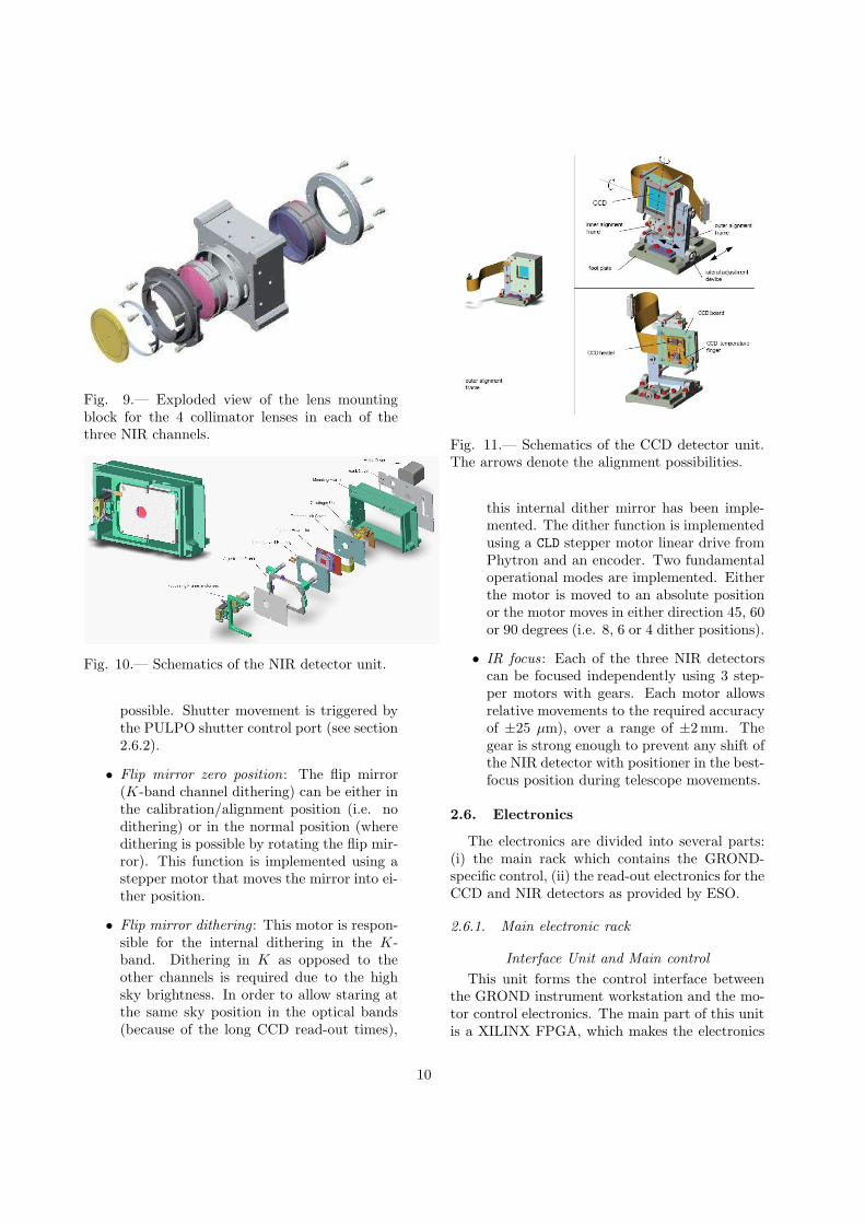
Fig. 9.— Exploded view of the lens mountingblock for the 4 collimator lenses in each of thethree NIR channels.
Fig. 10.— Schematics of the NIR detector unit.
possible. Shutter movement is triggered bythe PULPO shutter control port (see section2.6.2).
• Flip mirror zero position: The flip mirror(K-band channel dithering) can be either inthe calibration/alignment position (i.e. nodithering) or in the normal position (wheredithering is possible by rotating the flip mir-ror). This function is implemented using astepper motor that moves the mirror into ei-ther position.
• Flip mirror dithering: This motor is respon-sible for the internal dithering in the K-band. Dithering in K as opposed to theother channels is required due to the highsky brightness. In order to allow staring atthe same sky position in the optical bands(because of the long CCD read-out times),
Fig. 11.— Schematics of the CCD detector unit.The arrows denote the alignment possibilities.
this internal dither mirror has been imple-mented. The dither function is implementedusing a CLD stepper motor linear drive fromPhytron and an encoder. Two fundamentaloperational modes are implemented. Eitherthe motor is moved to an absolute positionor the motor moves in either direction 45, 60or 90 degrees (i.e. 8, 6 or 4 dither positions).
• IR focus : Each of the three NIR detectorscan be focused independently using 3 step-per motors with gears. Each motor allowsrelative movements to the required accuracyof ±25 µm), over a range of ±2mm. Thegear is strong enough to prevent any shift ofthe NIR detector with positioner in the best-focus position during telescope movements.
2.6. Electronics
The electronics are divided into several parts:(i) the main rack which contains the GROND-specific control, (ii) the read-out electronics for theCCD and NIR detectors as provided by ESO.
2.6.1. Main electronic rack
Interface Unit and Main control
This unit forms the control interface betweenthe GROND instrument workstation and the mo-tor control electronics. The main part of this unitis a XILINX FPGA, which makes the electronics
10

more flexible. Each IO of this XILINX FPGA isdriven by a bidirectional bus driver and addition-ally ESD protected by a low capacitance diode ar-ray. The current design uses 98 pins for input and66 pins for output purposes, with 32 spare pins.
Communication interface: The communica-tion interface is realised by an onboard RS232 in-terface with two jumpers for speed selection. Thenominal operation speed is 115200 baud. A RS232server converts this signal to 100baseT for the in-strument workstation. To maximise reliability, aspecial command structure is used. After the de-tection of the sync byte, the interface unit starts atimeout counter. If a command is not completedwithin 8 ms, this command will be rejected and thewhole communication unit reset, so that this unitcan receive new commands immediately. This pro-tects the system from hanging due to incompletecommands.
Motor Control: The main control containsall electronics necessary for the digital control ofthe motor driver boards and position readout. Allsignals which are important for operation of themotor driver electronics (clock, boost, direction,reset), are delivered by the main control. Forall position-switch controlled stepper motors (IR-calibration, cold shutter, zero position), the digi-tal circuit prevents a motor overrun (i.e. an endswitch). This means that as long as the steppermotor is in between the two end-switches the di-rection will be determined by the user. If one ofthe end-switches is reached, the motor stops im-mediately and the direction is automatically re-versed. Likewise, these electronics are responsiblefor the readout of the resolver values and synchro-nisation with the stepper motors. Three resolversare controlled by the GROND electronics; one forthe flip mirror and two for the CCD shutters.
An additional offset register can be used to cal-ibrate the start position of the flip mirror. Themovement is bidirectional and commandable. Theaccuracy of the flip mirror position is about 5.4arcmin (4000 steps per full rotation). Contrary tothe flip mirror, the CCD shutter electronics haveonly one mode (4 × 90 degrees). The shutter iscommandable over the PULPO (see section 2.6.2)interface, which gives a single bit state to the shut-ter electronics that determines whether it is openor closed. A commandable offset register for eachCCD shutter helps the user to adjust the initial
open/close position. The accuracy of the shutteris also 5.4 arcmin, corresponding to 80 µm in thecenter of the opening.
Motor driver boards for stepper motors
The motor driver board has two independentdriver units. These boards are used for drivingthe NIR focusing stage, the cold shutter and thezero-position motors. Each driver unit has fourcurrent modes (boost, run, standby, off), whichare selected via two status bits. The current levelsfor the modes can be set using variable onboard re-sistors. Additionally, each driver unit has its owntemperature sensor, which prevents overheating.
Motor driver boards for linear motors
This board was specially developed for high cur-rent with linear motors. Linear motors are used formoving the M3 mirror and the main shutter doorin front of the entrance window. The board workswith two limit switches, between which the motorcan move. The forward–backward movement ofthe mirror is possible by software-controlled com-mand (from the GROND instrument workstation)or manually over a special control box at the tele-scope’s M1 mirror cell.
Resolver Boards
An AD2S82A represents the main part of theresolver board, which is a variable resolver-to-digital converter. The resolution of this converteris variable and can be set up to 16 bit, which meansthat a maximum resolution of approximately 20arcsec is possible. The sine-wave for the LTN re-solver is produced by the maximum high frequencywaveform generator Max038. This produces anoptimal signal for the resolver. A high speed volt-age follower is connected at the outlet side to pro-vide a high current driver for long cables. Likewisethe offset of the sine-wave can be adjusted witha voltage buffer. All resolver boards used in theGROND electronic rack have the following con-figuration: resolution: 16 Bit; peak-to-peak sinewave amplitude: 2 V; frequency: 10 kHz; offset:0V.
Finally, the primary power of all motor powersupplies is switched on by a zero crossing switch.This prevents a high inrush current on the mainpower line during switch on.
Temperature Control
The electronic rack has two temperature con-
11

trol systems. The temperatures of the NIR detec-tor system is monitored by Lakeshore temperaturecontrollers. Each of the three NIR detectors hasits own Lakeshore controller LS3314 which in turnhas two control loops: Loop1 with 50W maximumheating power is used to warm up and regulateparts of the baseplate. Loop2 with 1W maximumheating power controls the detector temperaturewith an accuracy of ±0.1 deg. The nominal oper-ating temperature of the GROND NIR detectorsis 65K.
For the optical CCDs, temperature sensors andcontrolled heaters are directly mounted to theCCD detector backside and controlled via PULPO(see section 2.6.2). Since each PULPO can controlonly one shutter, two PULPOs are incorporated inthe electronic rack. The nominal heating power ofthe PULPO is 7W in each circuit. For safety rea-sons, the power at the CCDs was reduced to 1 W.A third heater, also controlled by each PULPO,is mounted on each of the two clock-bias boardthermal shields, with 7W heating power.
2.6.2. Detector read-out electronics
IRACE: The readout system for the infrared de-tectors, the IRACE (Infrared Detector High SpeedArray Control and Processing Electronics; Meyeret al. 1998) system, was supplied by ESO. As read-out mode (IMODE), the double-correlated mode isused, as it is the only valid mode for science obser-vations. One change was made to the basic IRACEsystem, namely to read out all three detectors si-multaneously and store the data into one FITSfile.
FIERA: The FIERA (Fast Imager ElectronicReadout Assembly; Beletic et al. 1998) system wasalso provided by ESO. Implemented changes in-clude (i) independent read-out for two pairs ofCCDs; (ii) a 3.8m instead of the nominal 1.8mcable to the front-end electronics (which does notincrease readout noise). For GROND, the two-port readout of each detector is used and one FITSfile with four separate extensions is written aftereach exposure (the two read-out ports are com-bined into one image before writing to file). Fur-thermore, two read-out speeds are typically used:the fast mode (625 kpixel/s; read-out noise of ≈23e−) in the 4 min and 6 min observation blocks (see
4www.lakeshore.com/temp/cn/331dn.html
below), and the slow mode (50 kpixel/s, ≈5 e−) inall longer observation blocks. The FIERA systemincludes PULPO (Hadad & Sinclair 1998), a sep-arate electronics box used to measure and controltemperatures (via 3 heaters), measure the vacuumin the cryostat (two inputs), and to operate oneshutter.
3. GROND operation scheme
The GROND operation scheme is designed tobe as generic as feasible, but primarily suitablefor prompt, automatic GRB follow up observa-tions. Additionally, it should provide the basicfunctionality to perform observations of any other,non-transient object. However, operating a sevenchannel imager in a single cryostat implies vari-ous observational constraints which should be con-sidered in the creation of the observation blocks(OBs; Chavan et al. 2000). Each observation isbuilt by combining exposures (differing in num-ber and length) of the seven detectors based onan appropriate set of parameters. This approachprovides the most generic background for scienceobservations with the current instrument design.The most important parameters are the numberof telescope dither positions NTD, the number oftelescope pointings NTP, the number of exposuresin the g′ and r′ band NGR, the number of exposuresin the i′ and z′ band NIZ, the corresponding inte-gration times UITGR and UITIZ, the number of K
mirror dither positions NMD, the number of K mir-ror pointings NMP, the number of JHK exposuresin a single K mirror position NINT, the numberof stacked JHK exposures NDIT, and the JHK
integration time DIT.
In order to comply with the GROND scienceobjectives, different default OB types are definedfor autonomous observations of GRB afterglows.The OBs are named after the total integrationtime in the K band, namely 4 min, 8 min, 20 minand 40 min OBs, all with 4 different telescopedither positions, as well as 6 min, 12 min, 30 minand 60 min OBs with 6 telescope dither positions.
All parameters for GROND observations can beadapted for use in non-standard OBs, within theirconstraints as described above. However, all bandsand their readout have to be synchronised for tele-scope dithering, which means that the integrationtime of the optical bands must be adapted to the
12

Fig. 12.— Top: Overview of the shortest generic 4 min observation block for the FIERA configuration, i.e.the CCD exposures. The read-out (r.o.) of the detectors should not overlap with telescope dithering, as itadds substantial noise to the data. The parameters of the shown 4 min OB are: NTD=4, NGR=1, NIZ=2 andOMODE=0 (625 kpixel/s). With 2 exposures in the i′z′ channels during one exposure in the g′r′ channels, thedata in g′r′ are not read out, but an (empty) FITS-file is created (so-called dummy read-out). Descriptionsin the image apply to all equally colored regions (ORT ≡ CCD readout time, TDT ≡ telescope dithering time,IBT ≡ duration of a single infrared block, and OBT ≡ duration of the whole observation block). Bottom:
Substructure of the observation blocks for the infrared exposures. The read out of infrared detectors has tobe separated from the KS mirror dithering. The parameters underlying the shown substructure of infraredblocks are: NMD=6, NINT=1 and IMODE=0 (double correlated readout). (IRT ≡ infrared detectors read outtime, MDT ≡ K mirror dither time.)
13

parameters of the infrared observations (and/orvice versa). For non-standard OBs, this remainsthe responsibility of the user.
By default, one standard OB consists of fouror six telescope dither positions: NTD=NTP=4 or
6, each with six K band mirror dither positions(NMD=NMP=6). A total of NINT=1, 2, 5 and 10 sin-gle J , H and K integrations are possible at eachK mirror dither position.
A generic break-down of the shortest 4 min OBand the underlying structure in a single telecopedither position can be seen in Fig. 12. Schemes forthe other default OBs differ in the number of J ,H and K integrations (NINT) and telescope dither-ings (NTD), and the CCD detector read-out mode(OMODE).
4. Software
4.1. Instrument software
The GROND instrument software is based onthe standard ESO/VLT software environment5.The CCD detectors are handled as a normal ar-ray of 4 chips, each with 2-port read-out. Thesingle FIERA controller drives all 4 chips. Thetwo shutters are operated in parallel. In order tointegrate longer in the bluer (g′r′) channels, twospecial read-out modes were introduced: one thatdrives only the i′z′ CCDs (i.e. one can read outonly these two chips while leaving the image inthe other two intact) and a second read-out wherethe g′r′ chips are not wiped/reset at the start ofthe exposure. When combined, these two read-out modes allow a special operation mode whereone takes one g′r′ image for every two i′z′ frames.Thus, in the bluer channels the efficiency is signif-icantly improved due to the additional exposuretime. There is a resulting trade off between thedark time (between reset/wipe and read-out) andthe exposure time in the g′r′ channels. The lattercannot be precisely known because of the not ex-actly predictable overhead of a FIERA exposure.As the dark current is negligible in the CCDs, thistrade off is justified. For very short exposures ofvery bright targets a fast read-out mode is alsoprovided, which reduces the read-out time from46 s to 4.4 s.
The near-IR chips are operated normally. The
5www.eso.org/projects/vlt/sw-dev
3 chips with 4 amplifiers each are treated as 12video channels and are stored in a single frame.This implies that all three chips must be read outtogether. As a consequence, the efficiency of theJH channels are slightly reduced: This is becausethe integration time for faint targets is limited bythe sky brightness in the K-band to ∼10 secondswhile the other two bands could, in principle, inte-grate longer. This results in a 2 second overhead.In addition, the JH chips must also wait for thedither mirror movements resulting in an additional0.5 sec overhead for each mirror movement. Thereis no additional read-out noise due to the largernumber of JH reads since the total noise is dom-inated by Poisson noise of the sky background.
The two arms (optical and near-IR) are oper-ated in semi-parallel. Both detector systems arestarted independently consecutively (within mil-liseconds) and the requested number of frames aretaken with as little dead time as possible. In gen-eral the two detector systems are not synchronised– except after telescope slews.
The instrument control software has no provi-sions to fill the time available between telescopemovements. It is the user’s responsibility to re-quest the optimal number of exposures. In orderto ease this task, a few optimal configurations areoffered.
Relatively frequent telescope offsets are re-quired to be able to determine the sky variationsin the J and H band (the K-band is handled bythe built-in dither mirror). in order to increaseefficiency and to simplify usage, the dither pat-tern is a predefined circle – the user only definesthe number of dither positions. GROND uses so-called ’combined offsets’, i.e. guiding continueswithout operator interaction after a telescope off-set. The operator is only required to select theguide star at the beginning of an OB.
Observations, both in visitor and service mode,are done through OBs. The user can use the nor-mal p2pp tool (P2PP Manual 20076) like for anyESO instrument (despite GROND not being an of-ficial ESO instrument). In the case of GRB obser-vations, OBs are generated in real time by a spe-cial process. The input parameters are providedby the GROND pipeline host (see next section),
6see www.eso.org/observing/p2pp/P2PP-tool.html#Manual
14

which is translated into a standard OB. To reduceoverheads, the instrument workstation always pro-vides the current telescope pointing to the pipelinemachine. Thus, the pipeline may conclude thatthe current pointing is ’good enough’ (i.e. the aimcoordinate and error circle fall within the field-of-view of the optical CCDs) and skip the telescopepreset. In this case guiding will continue withoutoperator interaction, even when executing severalOBs consecutively (guiding does not stop at theend of an OB). At the start of each OB, the in-strument is focused by moving M2 (see §5.3. AsGROND is fine-tuned for GRB follow-up wherespeed is crucial, no manual focusing is foreseenbefore a GRB observation starts – but the neces-sary templates are available for standard observingruns.
To make data analysis easier, all images pro-duced by GROND contain important informa-tion in the FITS headers. Thus, the imagescan be fed into standard software such as IRAFas the required header cards describing thebias/trim/overscan regions and amplifiers are in-cluded. The visual channels are also identified bythe header (g′r′i′z′); the infrared channels are inone image (see above). Obviously, all other rel-evant parameters (gain, read-out noise, etc.) arealso included for each chip in the header.
Crude astrometry (WCS cards) is also includedin each image. In the optical the astrometry is cor-rect, apart from a shift introduced by the pointingof the telescope. The astrometry is correct for allchips (i.e. individual chip shifts, rotations, etc. areincluded). As there are no significant distortionsin the optical channels, the astrometry is very ac-curate (0.′′2) – once the pointing origin is fixed.In the near-IR channels, the astrometry does not
include the focal plane distortions (which is signif-icant due to the focal reducer). Furthermore, thenear-IR detector system produces a single imageso an extra processing step is required to slice theimage into the three bands and to extract the nec-essary information from the header. The headercards also take into account the K-band ditheringmirror position.
4.2. The GROND Pipeline I: Observation
scheduling
The GROND Pipeline (GP) system is a soft-ware package designed and written specifically for
GROND. Its prime objective is to schedule rapidGRB afterglow observations (part I; described inthis section) and determine the redshift as quicklyas possible (part II; described in the §4.3). Allthe components of the GP are deployed on a PC –the so-called pipeline machine – which is locatedin the telescope building.
The coordinates of a GRB are distributed to theworld through the Gamma-ray bursts CoordinatesNetwork (GCN) in a few seconds (Barthelmy et al.2000). GROND reacts to GCN notices. The ar-chitecture of the GP is based on an asynchronousframework to provide speed and the degree of free-dom necessary to apply different analysis strate-gies. In the context of the GP system, asynchronymeans that all tasks of Tab. 1 are distributedamong different processes which do not run se-quentially but asynchronously.
The GP mainly consists of two layers, thesystem layer and the GRB analysis layer (seeTab. 1). The system layer consists of the pro-cesses that receive the GRB alerts, decide whetherto follow that burst or not, schedule and re-schedule observations and conduct the observa-tions by initiating, continuing, interrupting orending them. Furthermore, the main system pro-cess controls all processes including the analysisprocesses, and coordinates the interprocess com-munication. The GRB analysis layer containspre-processing of the images, photometric analy-sis, identifying the GRB afterglow, spectral energydistribution (SED) analysis and photometric red-shift determination.
The details of the processes are described in aseparate paper (Yoldas et al.; in prep.).
4.2.1. Receiving GRB Alerts
When a GRB alert comes in via the GCN socketconnection7, the main process extracts all the in-formation from the packet by parsing it accord-ing to its type. It first checks whether it is apacket for an existing GRB or a new target forthe system. Then the decision tree splits accord-ing to packet types. Based on this information andthe pre-defined user decision on the target type,the system decides whether to follow-up. For anew target, the visibility of the target is calcu-lated independent of the autonomous decision of
7see gcn.gsfc.nasa.gov/gcn describe.html
15

Table 1: The duties of the system and the GRB analysis layers of the GP.
System - Observation Control Layer GRB Analysis LayerReceiving GRB alerts Pre-processing the imagesDeciding whether to observe the target Photometric analysis of 7-band dataCalculating visibility of the target Constructing the SED of the objectsScheduling of the observations Identifying the GRB afterglowTriggering/continuing/stopping observations Determining the photometric redshiftProviding web-interface for user interaction Evaluating the accuracy of the redshift
the software to follow or not. The visibility cal-culations utilize skycalc, a C program written byJohn Thorstensen8, with a python wrapper. Thevisibility of the object is normally calculated forthe given/current time or the upcoming night. Ifit is observable and does not conflict with otherchecks (e.g. Moon distance), then it is scheduledfor observation. Scheduling means that the mainprocess prepares an observation plan of the target(which typically will contain several OBs, possi-bly also of different lengths), satisfying the above-defined criteria, and tries to schedule it with theother observation plans, if any exist.
4.2.2. Scheduling of Observations
The scheduling of observations for GRONDneeds to be fully automated like the other parts ofthe system, but at the same time it should allowusers to modify, add, and delete the scheduled ob-servations. Furthermore, the automatically sched-uled observations may be deleted by the system,as a result of a “Retraction” or a later “Ignore”decision derived from the GCN packets for thattarget.
Some of the other robotic or automated tele-scope systems, e.g. the Liverpool telescope(Guidorzi et al. 2006) use “just in time” (jit)scheduling which is based on choosing the ob-servation to be conducted instantly at every timerather than scheduling a set of observations fora whole night. jit scheduling is not suitable forGROND because i) ideally, all GRBs should beobserved that occur on the same night and thatare visible; however, jit scheduling does not allowthe system to foresee the night and hence arrangethe observation durations accordingly; ii) the usershould be able to interact with and modify the
8see www.eso.org/observing/skycalc notes.html
schedule, e.g. to implement other priorities basedon other information (short duration GRB, orGRB at high redshift); iii) GROND shares thetelescope with two other instruments for whichthe observers/operators want to know the sched-ule of the upcoming hours. Therefore, we devel-oped our own scheduling system that fulfills allthe requirements of GROND. The resolution ofconflicts between competing observation plans isdone based on a priority scheme. By definition, atthe times when the planned observations need tobe re-scheduled, the observation plan with higherpriority can partially or totally override anotherobservation plan with lower priority. For GP, thelatest burst has the highest priority. However, theusers can also change the priority of any observa-tion.
4.2.3. Automating the GRB Afterglow Observa-
tions
When the start time of an observation is con-firmed, the GP system triggers the Rapid Re-sponse Mode (RRM9) by sending the coordinatesof the target and the name of the observation blockto be used to a dedicated directory. The RRM pro-cedure has been widely used for the VLT, and wasimplemented at the La Silla site for GROND oper-ations on the 2.2 m telescope. A RRM acquisitiontemplate ends any ongoing observation, slews thetelescope, and sets up GROND. After the RRMtrigger, the next observation blocks are sent di-rectly via the Instrument Work Station (IWS),rather than the dedicated RRM directory. Be-cause the GP system does not have direct con-trol over the GROND instrument, commands andOBs are relayed through the IWS using a specifi-cally designed communication protocol. Once theRRM is accepted, the main process of the GP
9see www.eso.org/observing/p2pp/rrm.html
16

system creates a GRB process called GRBServer.This GRB process controls several sub-processes,responsible for the analysis of all the 7-channelimages obtained for that observation, created bytypically several subsequent OBs.
4.3. The GROND Pipeline II: Analysing
GRB Afterglow Observations
The analysis of GROND GRB afterglow obser-vations are conducted on the fly, managed andcontrolled by the GP system. When an observa-tion is executed, images appear in a certain direc-tory, as the data handling system (DHS) of ESOpulls them from the IWS and stores them in a datadirectory on the pipeline machine. The analysis ofeach image starts immediately after it appears inthe data directory.
The steps of the data analysis depend on thestructure of the OB and the choice of the analysisstrategy by the users. In total 22 combinationsof data analysis strategies utilizing different pro-cesses chosen from a total of 12 are available. Theaim is to construct as quickly as possible a spec-tral energy distribution (SED) of the target objectto determine its photometric redshift.
In all strategies, the single band images are cor-rected for the dark current and bias, introducedby the detector and detector electronics, and themultiplicative effects, i.e. the pixel-to-pixel sen-sitivity and the illumination variations across theimage. The remaining steps, including i) correc-tion for the geometrical distortion introduced bythe focal reducer lenses in front of the infrared de-tectors, ii) sky subtraction for the infrared images,iii) shifting and adding of the images obtained atdifferent telescope positions (dithered), vary de-pending on the strategy. Overall, different strate-gies can be grouped into two, depending on whenthe astrometric and photometric analyses are con-ducted. The astrometry and photometry can beconducted either only on the images acquired atthe same telescope position, or at the end of anOB. All the analysis processes until the identifi-cation of the GRB afterglow utilize Pyraf/IRAFlibraries10. Astrometry is done by matching the
10IRAF (see iraf.noao.edu) is a data reduction andanalysis software package of NOAO, and Pyraf (seewww.stsci.edu/resources/software hardware/pyraf) is aPython wrapper for IRAF, provided by the Space Tele-
Fig. 13.— The error in GROND’s photometricredshift determination of GRB afterglows is ex-pected to be smaller than ±0.3 for most of the red-shift range. Only for redshifts where the Ly breakfalls between the z′ and J bands, i.e. z ≈ 8, doesthe accuracy disimprove. The solid line shows thesimulated error in redshift when assuming ±0.5mag relative photometric accuracy between the 7bands. The relatively good performance aroundz ∼ 6 is due to the narrow i′ band in GROND.The dotted line shows the (larger) error when inaddition one assumes an intrinsic GRB host ex-tinction of AV=1 which is not accounted for inthe fit. For low redshifts there is hardly any dif-ference since the NIR bands provide a precise leverarm.
objects detected in the images with those that arein the optical or infrared catalogs, namely USNOA-2, USNO B1, DENIS, 2MASS, NOMAD andGSC22 which are downloaded via the internet11.
The objects found in each of the 7 bands arematched based on their world coordinates, af-ter the photometric analysis. The result of thematch gives us SEDs of all the objects detected inan OB. The identification of the GRB afterglowamong the many objects detected in the image isbased on a figure-of-merit approach. Marks aregiven to each object as a result of several tests,namely whether i) the object is inside the areagiven by the gamma/X-ray/optical position uncer-tainty distributed by GCN packets, ii) the coordi-nates of the object match with any object in the
scope Science Institute.11vizier.u-strasbg.fr/viz-bin/VizieR
17

Fig. 14.— Cut-out view of GROND at the tele-scope with the new M3 within the light baffle.
catalogs, iii) the magnitudes of the object showvariability in time, and iv) the colors of the ob-ject resemble those of other GRB optical/infraredafterglows (Rhoads 2001).
Before the SEDs of the best candidates are anal-ysed by the publicly available HyperZ code (Bol-zonella et al. 2000), they are first tested for a Lybreak. A single and a broken power-law modelare fit to the SED of each object, and three testsare applied on the results of these fits in orderto decide whether the Ly break is covered by thedata. The redshift range that can be observed byGROND is z ∼ 3.5 – 13. The HyperZ tests weconducted with simulated and real afterglow datashowed that HyperZ is able to determine the red-shift with an accuracy of ∆z ∼ 0.3 – 0.5 (see Fig.13), if the data cover the Lyman feature.
5. GROND at the 2.2m telescope
The 2.2m MPI/ESO telescope is the obviousfirst choice for GROND. In order to detect a largefraction of GRBs, a 2 m class telescope is a min-imal requirement. Working within the ESO en-vironment would allow follow-up observations atthe VLT with rather simple procedures as well asproviding the (European) GRB community withunique data. Moreover, it was expected that thepressure on the 2.2m MPG/ESO telescope mightdecrease once VST and VISTA become opera-tional.
5.1. M3
In order to produce the smallest possible im-pact on the operation of the other two instru-ments on the 2.2m telescope, the Wide Field Im-ager (WFI12) and the fiber-fed Echelle spectro-graph FEROS13, we designed a movable M3 mir-ror which, in case of a GRB alert, is folded in andreflects the light off towards the side of the tele-scope (Coude-like focus) where GROND is per-manently mounted. This leaves the common-userinstruments WFI and FEROS unaffected at theCassegrain focus of the telescope. Since GRONDobservations start as soon as possible after a GRBalert, the switching mechanism had to be fast,rigid, and reproducible in its alignment.
The M3 mirror itself has an elliptical shape witha dimension of 492 × 324 × 60 mm3. The dimen-sions of the mirror are large enough to guaranteethat additional off-axis light is available for a guid-ing camera sitting on top of the GROND vessel(see §5.4). The mirror consists of CeSIC (carbon-fiber reinforced silicon carbide). The advantageof this material for our application is its low den-sity and high rigidity so that the weight of the M3mirror is only 8.2 kg; the mass of the total mov-able part is 23.5 kg. Also, this material allows themirror and support structure to be thin enoughthat no obstruction occurs when in the up-rightposition for WFI/FEROS observations.
The complete M3 mirror system (Fig. 14) canbe switched to the GROND position within about20 seconds. The accuracy of the alignment withthe optical axis was tested several times and foundto be better than 10′′.
5.2. Pointing Model
Due to the very asymmetric position of theGROND cryostat vessel on one side and the elec-tronics on the opposite side of the telescope center-piece, a new pointing model had to be created us-ing the TPOINT package (Wallace 2007). In addi-tion to the components used for the Cassegrain in-strumentation, two new components (HCEC andHCES, both unrelated to the GROND assembly,but correcting an earlier omission) were added inmodelling the offsets of the 100 stars which had
12www.ls.eso.org/lasilla/sciops/2p2/E2p2M/WFI/13www.ls.eso.org/ lasilla/sciops/2p2/E2p2M/FEROS/
18

been measured at different azimuth and elevationangles. The effect of GROND on the pointingmodel is absorbed by those components which hadalready been implemented (most notably the forkflexure and the tube flexure). The resulting point-ing model leaves an rms scatter of 5′′ for both,GROND and WFI (without the compromise of en-suring a good WFI/FEROS pointing it would be<∼2′′).
5.3. Pointing direction dependent Focus
Due to the location of the GROND camera onthe centerpiece, the bending of the telescope atdifferent sky positions introduces a variable focuschange. This focus change only depends on thedeclination, since bending in the plane of the tele-scope fork only leads to a lateral displacement ofthe beam away from the optical axis, but not afocus change. The focus changes correspond toabout 60 µm of M2 movement between zenith and70◦ zenith distance, as compared to the 66 µmfocus change induced by a 1 degree temperaturechange. Switching in/out the M3 mirror repro-duces the focus to within ±8µm. Automatic re-focusing has been implemented at the templatelevel and thus is executed at each start of an OB.In addition to the temperature T, the focus for-mula (F= const. - 66*T - 80* cos(DD); in unitsof µm) accounts for the telescope position in theNorth-South direction (DD is the declination dif-ference relative to zenith).
5.4. Guiding
In accordance with ESO standards it wasmandatory for GROND to be equipped with aguide camera. In order to ease integration withthe existing telescope control system. the “NewGeneration Technical CCD” (NGTCCD14) sys-tem of ESO with a 1K×1K E2V chip was imple-mented. In view of the semi-robotic operation,a field of view large enough to always contain astar brighter than V ∼ 15 mag was deemed nec-essary. Therefore, the f/8 beam of the telescopewas re-imaged to yield a 0.′′33/pix plate scale, anda FOV of 5 arcmin across. The NGTCCD wasplaced outside of the main GROND vessel, and isfed by a pick-off mirror (M4) next to the entrance
14ftp://ftp.eso.org/pub/vlt/vlt/pub/releases/JAN2006/vol-4/VLT-MAN-ESO-17240-3558.pdf
window of GROND (Fig. 15). A folding mir-ror (not shown in Fig. 15) is introduced betweenthe triplet lens system and the detector to easemounting on the GROND vessel. The M4 pick-upmirror is a weakly spherical mirror (80 km radiusof curvature) which is slanted by 2◦ relative to astandard symmetric use, thus minimizing astig-matism. The triplet lens system adapts the platescale to the chosen detector (pixel size and num-ber). The guide camera’s FOV is located 23′ southof the main GROND imaging FOV.M3 Plane GuideCameraM4 TripletGRONDEntran eWindow
TelesopeFo usFig. 15.— Layout of the guide camera, with theM4 pick-off mirror next to the entrance window.
6. Calibration and performance
GROND was mounted at the 2.2m telescope inApril 2007 (Fig. 16), and saw first light on thesky on April 30 (Fig. 17). GROND has been run-ning smoothly since. Particularly noteworthy arethree effects: (i) there has been no need for contin-uous pumping; the CCC acts as a cryo-pump, andkeeps the vacuum stable at ≈ 5 × 10⁻⁸ mbar; (ii)the NIR detector focusing stages remained stablewithin the depth of focus over the first few months;(iii) no effects of flexure have been recognised.
First calibration observations included thederivation of zeropoints for all seven bands, checksfor vignetting and flexure, the determination ofthe focus formula (see §5.3), and the effect of theK-band dither mirror.
19
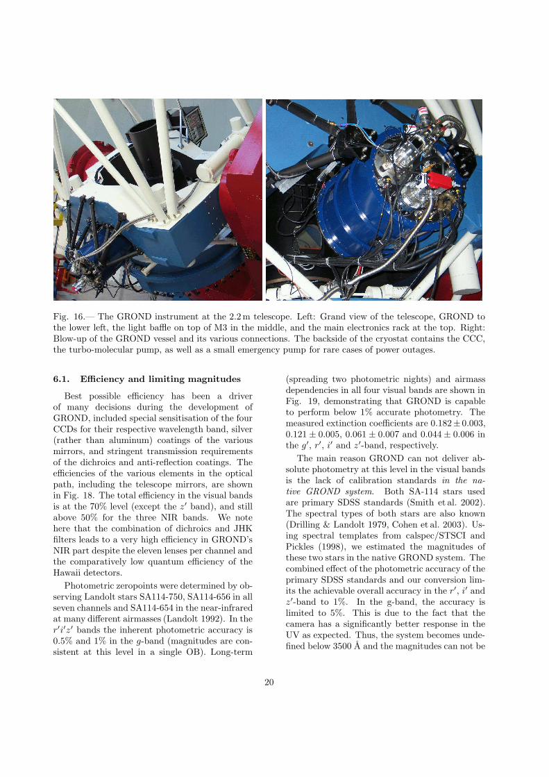
Fig. 16.— The GROND instrument at the 2.2m telescope. Left: Grand view of the telescope, GROND tothe lower left, the light baffle on top of M3 in the middle, and the main electronics rack at the top. Right:Blow-up of the GROND vessel and its various connections. The backside of the cryostat contains the CCC,the turbo-molecular pump, as well as a small emergency pump for rare cases of power outages.
6.1. Efficiency and limiting magnitudes
Best possible efficiency has been a driverof many decisions during the development ofGROND, included special sensitisation of the fourCCDs for their respective wavelength band, silver(rather than aluminum) coatings of the variousmirrors, and stringent transmission requirementsof the dichroics and anti-reflection coatings. Theefficiencies of the various elements in the opticalpath, including the telescope mirrors, are shownin Fig. 18. The total efficiency in the visual bandsis at the 70% level (except the z′ band), and stillabove 50% for the three NIR bands. We notehere that the combination of dichroics and JHKfilters leads to a very high efficiency in GROND’sNIR part despite the eleven lenses per channel andthe comparatively low quantum efficiency of theHawaii detectors.
Photometric zeropoints were determined by ob-serving Landolt stars SA114-750, SA114-656 in allseven channels and SA114-654 in the near-infraredat many different airmasses (Landolt 1992). In ther′i′z′ bands the inherent photometric accuracy is0.5% and 1% in the g-band (magnitudes are con-sistent at this level in a single OB). Long-term
(spreading two photometric nights) and airmassdependencies in all four visual bands are shown inFig. 19, demonstrating that GROND is capableto perform below 1% accurate photometry. Themeasured extinction coefficients are 0.182± 0.003,0.121 ± 0.005, 0.061 ± 0.007 and 0.044 ± 0.006 inthe g′, r′, i′ and z′-band, respectively.
The main reason GROND can not deliver ab-solute photometry at this level in the visual bandsis the lack of calibration standards in the na-
tive GROND system. Both SA-114 stars usedare primary SDSS standards (Smith et al. 2002).The spectral types of both stars are also known(Drilling & Landolt 1979, Cohen et al. 2003). Us-ing spectral templates from calspec/STSCI andPickles (1998), we estimated the magnitudes ofthese two stars in the native GROND system. Thecombined effect of the photometric accuracy of theprimary SDSS standards and our conversion lim-its the achievable overall accuracy in the r′, i′ andz′-band to 1%. In the g-band, the accuracy islimited to 5%. This is due to the fact that thecamera has a significantly better response in theUV as expected. Thus, the system becomes unde-fined below 3500 A and the magnitudes can not be
20

Fig. 17.— First scientific demonstration resultfrom April 30, 2007: green crosses are the GRONDcamera photometric estimates as derived from a 8min observation block of the quasar PKS 1251-407. The derived photometric redshift is z=4.44,compared to the spectroscopic redshift of z=4.46.The red line is the composite quasar spectrumfrom Francis et al. (1991).
converted to the native system of the instrument.To demonstrate that the g′-band can perform justas accurately, we introduced an external UV filtertemporarily that cuts all UV flux. With this cor-rection, the accuracy of the g′-band is also around1% – slightly worse than the other three bandsas the templates used are not sufficiently accuratearound the 4000 A break. Unfortunately the op-tical quality of our UV filter was so bad that itprevents scientific use. Consequently, a filter willbe introduced the camera in March 2008.
In the near-IR bands, magnitudes are only ac-curate to 3% in single (10 sec) frames. Due to thesignificantly lower accuracy and the significantlylower extinction coefficients (which are water con-tent dependent in any case – i.e. they are differentevery night) the near-IR performance can only bedetermined by observing long-term trends. Cur-rently we accept zeropoints of 22.97, 22.22 and21.51 in J , H and K, respectively, for 1 sec inte-gration time and airmass of 1. Until more datais collected, we will use nominal extinction coeffi-cients of 0.12 (J), 0.06 (H) and 0.07 (K).
Updates of these performance values will beposted at www.mpe.mpg.de/˜ jcg/GROND.
Fig. 19.— Airmass dependence of the photometriczeropoint in the visual bands. Magnitudes are inthe Vega system and the zeropoint is calculated for1 s integration and for ADU (i.e. not electrons).The extinction coefficients and the extrapolatedzeropoint at an airmass of 1 are shown for all fourbands.
6.2. Photometric system transformations
A first set of calibration observations was per-formed during mid-July 2007, though not inphotometric conditions. Thus, the constants inthe following equations may change slightly (seewww.mpe.mpg.de/˜ jcg/GROND for updates).
First, we derive transformation equations bet-ween the GROND (G) visual bands and the Sloan(S) filter system:
g′G
= g′S+(0.000± 0.001)+(0.105±0.014)× (u′−
g′)S + (0.036 ± 0.024)× (g′ − r′)Sr′G
= r′S+(−0.001±0.001)+(0.056±0.011)×(g′−
r′)S + (−0.089± 0.022)× (r′ − i′)Si′G
= i′S
+ (−0.001 ± 0.001) + (−0.029 ± 0.007) ×(r′ − i′)S + (0.004 ± 0.011)× (i′ − z′)Sz′G
= z′S+(−0.001±0.001)+(0.034±0.003)×(i′−
z′)S.
Next, the transformations between the GRONDNIR bands and the 2MASS (2M) system are asfollows:
21

Table 2: Zeropoints and 3σ limiting magnitudesfor an 8 min observation block with four tele-scope dither positions (corresponding to an effec-tive exposure time of 4×130 sec in the visual and4×12×10 sec in the NIR channels) for the sevenGROND channels at the 2.2m telescope. The er-ror in the zeropoint is about ±0.03 mag. Thelimiting magnitudes in the NIR are the mean val-ues; they exhibit seasonal variations by up to ±0.5mag.
GROND zeropoints (mag) lim. magnitudechannel Vega AB in 8 min OB
g’ 25.61 25.62 24.2r’ 25.63 25.78 24.2i’ 24.57 24.96 23.7z’ 24.50 25.01 23.5J 22.97 23.88 21.4H 22.22 23.60 20.4K 21.51 23.30 19.0
JG = J2M + (−0.003± 0.001) + (0.005 ± 0.001)×(J − H)2MHG = H2M + (0.002 ± 0.001) + (0.021 ± 0.001) ×(J − H)2MKG = K2M + (−0.003± 0.001)+ (0.094± 0.003)×(J − K)2M.
For transformation from 2MASS to other systemssee Carpenter (2003).
Finally, the transformations between the visualGROND bands and the WFI (W) system are:
g′G
= BW +(0.001±0.012)+(0.132±0.022)×(U−
B)W + (−0.127± 0.053)× (B − V )Wr′G
= VW +(0.001±0.001)+(0.039±0.023)×(B−
V )W + (−0.852± 0.024)× (V − R)Wi′G
= RW + (0.016 ± 0.003) + (−0.163 ± 0.046) ×(V − R)W + (−0.485± 0.044)× (R − I)Wz′G
= IW + (0.012 ± 0.002) + (−0.089 ± 0.005) ×(R − I)W.
Only for the r′ band we reach a residual 1% rmsscatter, while for i′ and z′ the residual rms scatteris 2%. For a transformation to the standard Lan-dolt (Johnson BV and Cousins RI) system see thededicated WFI Web-page15.
15www.ls.eso.org/lasilla/sciops/2p2/E2p2M/WFI/zeropoints/
7. Summary
GROND is an imaging system capable of oper-ating in seven colors simultaneously. It has beendesigned and built at MPE Garching, and com-missioned at the 2.2m MPI/ESO telescope on LaSilla, Chile. First observations show that all prop-erties are according to specifications/expectations.The first observations of gamma-ray bursts withGROND have also been obtained (Greiner et al.2007a,b; Primak et al. 2007, Kruhler et al. 2007).Fine tuning of the operations strategy as well asscheduling and analysis software in the upcomingweeks is expected to bring GROND into a fully op-erational condition, thus allowing the commence-ment of normal science operations.
We thank K. Meisenheimer, R.-R. Rohloff andR. Wolf (all MPIA Heidelberg) for their support ingetting the telescope interfaces right, and for FEcomputations of the M3 mirror rigidity. Particularthanks to the whole La Silla Observatory staff fortheir enthusiasm and effort during the assembly ofall the GROND components to the telescope. Wethank D.H. Hartmann (Clemson Univ.) for stim-ulating discussions, K. Garimella (formerly alsoClemson Univ) and D.A. Kann (Tautenburg Ob-servatory) for help in implementing SED-fittingroutines as preparatory steps for HyperZ, as wellas A. Rossi (Tautenburg Observatory) for supportin the derivation of the photometric conversionequations. We are greatful to the anonymousreferee for the many detailed comments whichimproved to readability and consistency of the pa-per. We greatly acknowledge the special efforts ofthe following companies to fulfil our often unusualrequirements: Berliner Glas KGaA, ECM Moosin-ning, FEE GmbH Idar-Oberstein, Korth KristalleGmbH Altenholz, Laseroptik GmbH Garbsen,Laser Zentrum Hannover e.V., PrazisionsoptikGera, Steinbach-Konitzer-Lopez Jena, TafelmaierDunnschichttechnik Rosenheim. Part of the fund-ing for GROND (both hardware as well as person-nel) was generously granted from the Leibniz-Prize(DFG grant HA 1850/28-1) to Prof. G. Hasinger(MPE).
Facilities: Max Planck:2.2m.
22

REFERENCES
Barthelmy S.D., Cline T.L., Butterworth P. et al.2000, AIPC 526, 731
Beletic J.W., Gerdes R., Duvarney R.C., 1998,Proc. ESO CCD workshop, Garching, 8-10Oct. 1996, Eds. J.W. Beletic and P. Am-ico, Kluwer, ASSL 228, p. 103 (see alsowww.eso.org/projects/odt/Fiera)
Bolzonella M., Miralles J.-M., Pello R. 2000, A&A363, 476
Carpenter J.M., 2003, www.astro.caltech.edu/-˜ jmc/2mass/v3/transformations/
Chavan A.M., Silva D.R., Boarotto C., CanavanT., Kemp R., Giannone G., 2000, in Proc. “Ob-servatory Operations to Optimize Scientific Re-turn II”, ed. P.J. Quinn, SPIE Vol. 4010, p. 81
Cohen M., Megeath S.T., Hammersley P.L. et al.2003, AJ, 125, 2645
Depoy D., 1998, URL www.astronomy.ohio-state.edu/˜depoy/research/instrumentation/andicam/andicam.html
Dhillon V.S., Marsh T.R., Stevenson M.J., et al.,2007, MN 378, 825
Drilling J.S., Landolt A.U., 1979, AJ 84, 783
Dunham E.W., Elliot J.L., Bida T.A., et al. 2004,SPIE 5492, 592
Ellis T., Drake R., Fowler A.M., Gatley I., HeimJ., Luce R., Merrill K.M., Probst R., BuchholzN., 1992, in Proc. SPIE 1765, 94
Francis P.J., Hewett P.C., Foltz C.B. et al., 1991,ApJ 373, 465
Fukugita M., Ichikawa T., Gunn J.E. et al. 1996,AJ 111, 1748
Gehrels N., Chincarini G., Giommi P., et al. 2004,ApJ 611, 1005
Greiner J., Clemens C., Kruhler T., et al. 2007a,GCN #6449
Greiner J., Clemens C., Kruhler T., et al. 2007b,GCN #6694
Guidorzi C., Monfardini A., Gomboc A., et al.,2006, PASP 118, 288
Hadad N., Sinclair P., 1998, Proc. ESO CCDworkshop, Garching, 8-10 Oct. 1996, Eds. J.W.Beletic and P. Amico, Kluwer, ASSL 228, p.131 (see also www.eso.org/projects/odt/Fiera)
Jewitt D.C., 2002, AJ 123, 1039
Jha S., Charbonneau D., Garnavich P.M. et al.2000, ApJ 540, L45
Kann D.A., Klose S., Zhang B., et al., 2008, ApJ(subm; astroph/0712.2186)
Kotani T., Kawai N., Yanagisawa K., et al. 2005,Il Nuovo Cim. 28 C, p. 755 (astro-ph/0702708)
Kruhler T., Greiner J., Afonso P., Kupcu-YoldasA., Yoldas A., Szokoly G., GCN Circ. #7021
Landolt A.U., 1992, AJ 104, 340
Lamb D.Q., Reichart D.E., 2000, ApJ 536, 1
Laux U., 1999, Astrooptik, Sterne und Weltraum,Munchen, 2nd ed.
Meyer M., Finger G., Mehrgan H., Nicol-ini G., Stegmeier J., 1998, in Proc. “In-frared Astronomical Instrumentation”, ed.A.M. Fowler, SPIE Vol. 3354, p. 134 (see alsowww.eso.org/projects/iridt/irace)
Orosz J.A., Bailyn C.D., 1997, ApJ 477, 876
Paczynski B., 1986, ApJ 304,1
Pickles A.J., 1998, PASP 110, 863
Primak N., Szokoly G., Greiner J., et al. 2007,GCN #6590
P2PP (Phase2 Proposal Preparation) Manual,2007, v. 2.13, Issue 9, Doc. No. VLT-MAN-ESO-19200-1644
Reif K., Bagschik K., de Boer K.S., et al., 1999,SPIE 3649, 109
Rhoads J.E., 2001, ApJ 557, 943
Ritchey G.W., 1928, JRASC 22, 207
Roth M.M., et al. 2006, PASP 117, 620
23

Smith J.A., Tucker D.L., Kent S., et al. 2002, AJ123, 2121
Taubenberger S., Pastorello A., Mazzali P.A., etal. 2006, MN 371, 1459
Vreeswijk P., Ledoux C., Smette A., et al., 2007,A&A 468, 83
Wallace P.T., 2007, www.tpsoft.demon.co.uk
Watanabe M., Nakaya H., Yamamuro T., et al.,2005, PASP 117, 870
Woche M.F., Laux U, Papamastorakis J., 2000,Proc. SPIE 4008, 930
This 2-column preprint was prepared with the AAS LATEXmacros v5.2.
24

0.7
0.8
0.9
1
Ref
lect
ivity
Telescope totalEntrance Window
Mirrors in GROND
0.1
0.3
0.5
0.7
0.9
Tra
nsm
issi
on
gr/iz dichroiciz/JHK dichroic
J/HK dichroicH/K dichroic
0.1
0.3
0.5
0.7
0.9
Tra
nsm
issi
on
g/r dichroici/z dichroic
Collimator opticsCamera optics
0.1
0.3
0.5
0.7
0.9
Tra
nsm
issi
on
g Filterr Filteri Filter
z Filter
J FilterH FilterK Filter
0.1
0.3
0.5
0.7
0.9
Qua
ntum
Effi
cien
cy
g CCDr CCDi CCD
z CCD
J DetectorH DetectorK Detector
0.1
0.3
0.5
0.7
400 500 600 700 800 900 1000 1200 1400 1600 2000 2400
Tot
al E
ffici
ency
Wavelength[nm]
g r i z J H K
GROND FILTER BANDS
Fig. 18.— Efficiency of the GROND instrument at the 2.2m telescope: Top panel: telescope and GROND-internal mirrors. Panels 2 and 3 from top: transmission of the dichroics, NIR lens systems, Panel 4: Trans-mission of the filters. Panel 5: Detector quantum efficiencies. Bottom panel: Total efficiency in each of theseven GROND bands. All losses are included, except the obstruction of M1 by M2. Except for the telescope(M1, M2) data, all curves represent measured data at their operating temperatures, i.e. all transmissionvalues for the lenses, dichroic and anti-reflection coatings refer to 80K. The measured efficiency in all sevenbands on the sky turns out to be within 10% of the one expected from the bottom panel.25