ground control management in western australian mining ...geotechnical considerations in open pit...
TRANSCRIPT

Government of Western AustraliaDepartment of Mines, Industry Regulation and Safety
Ground control management in Western Australian
mining operations
GUIDELINE

Government of Western AustraliaDepartment of Mines, Industry Regulation and Safety
GUIDELINE
Ground control management in Western Australian
mining operations

DisclaimerThe information contained in this publication is provided in good faith and believed to be reliable and accurate at the time of publication. However, the information is provided on the basis that the reader will be solely responsible for assessing the information and its veracity and usefulness.
The State shall in no way be liable, in negligence or howsoever, for any loss sustained or incurred by anyone relying on the information, even if such information is or turns out to be wrong, incomplete, out-of-date or misleading.
In this disclaimer:
State means the State of Western Australia and includes every Minister, agent, agency, department, statutory body corporate and instrumentality thereof and each employee or agent of any of them.
Information includes information, data, representations, advice, statements and opinions, expressly or implied set out in this publication.
Loss includes loss, damage, liability, cost, expense, illness and injury (including death).
ReferenceDepartment of Mines, Industry Regulation and Safety, 2019, Ground control management in Western Australian mining operations – guideline: Department of Mines, Industry Regulation and Safety, Western Australia, 29 pp.
ISBN 978 1 922149 69 5 (paperback) 978 1 922149 70 1 (web)
© State of Western Australia (Department of Mines, Industry Regulation and Safety) 2019
This publication is available on request in other formats for people with special needs.
Further details of resources safety publications can be obtained by contacting:
Safety Regulation Group – Regulatory Support Department of Mines, Industry Regulation and Safety 100 Plain Street EAST PERTH WA 6004
Telephone: 1800 SAFEMINE (1800 7233 6463)
NRS: 13 36 77
Email: [email protected]
The State of Western Australia supports and encourages the dissemination and exchange of its information. The copyright in this publication is licensed under a Creative Commons Attribution 4.0 International (CC BY) licence.
Under this licence, with the exception of the Government of Western Australia Coat of Arms, the Department’s logo, any material protected by a trade mark or licence and where otherwise noted, you are free, without having to seek our permission, to use this publication in accordance with the licence terms.
We also request that you observe and retain any copyright or related notices that may accompany this material as part of the attribution. This is also a requirement of the Creative Commons Licences.
For more information on this licence, visit creativecommons.org/licenses/by/4.0/legalcode
II

Ground control management in Western Australian mining operations – guideline III
ContentsForeword ........................................................................................................................................................................IV1 Introduction ............................................................................................................................................................V
1.1 Structure and scope ........................................................................................................................................................V2 Managing ground control .................................................................................................................................... 1
2.1 Approach ........................................................................................................................................................................... 12.2 Ground control management plan ............................................................................................................................... 1
3 Safe design ............................................................................................................................................................. 23.1 Geotechnical model ......................................................................................................................................................... 23.2 Mine design, planning and scheduling ......................................................................................................................... 83.3 Design methods ............................................................................................................................................................103.4 Design acceptance criteria and design events ........................................................................................................123.5 Mine closure ...................................................................................................................................................................13
4 Safe design implementation and review ........................................................................................................145 Managing hazardous or potentially unstable ground ..................................................................................16
5.1 Unstable ground .............................................................................................................................................................165.2 Mining through underground workings .....................................................................................................................16
6 Communication, training and supervision .....................................................................................................186.1 Communication and consultation processes ..........................................................................................................186.2 Geotechnical hazard maps ..........................................................................................................................................186.3 Incident reporting ...........................................................................................................................................................196.4 Training and assessment of competency .................................................................................................................196.5 Supervision ......................................................................................................................................................................19
7 Emergency response ..........................................................................................................................................20Appendix 1 Legislative provisions ............................................................................................................................21Appendix 2 Glossary ...................................................................................................................................................22Appendix 3 Example of GCMP structure ................................................................................................................25Appendix 4 Further information................................................................................................................................27

Ground control management in Western Australian mining operations – guidelineIV
GuidelinesA guideline is an explanatory document that provides more information on the requirements of legislation, details good practice and may explain means of compliance with standards prescribed in the legislation. The government, unions or employer groups may issue guidance material.
Compliance with guidelines is not mandatory. However, guidelines could have legal standing if it were demonstrated that the guideline is the industry norm.
This guideline updates the Department of Mines, Industry Regulation and Safety’s (the Department) now-superseded guidelines on geotechnical considerations in open pit and underground mines. It has an operations focus and is set out in the context of risk assessment and legislative requirements of all responsible persons. Consequently, each mining operation needs to understand its limitations and skills base.
Who should use this guideline?You should use this guideline if you have control of a mine (e.g. employer, Registered Manager, Quarry Manager, Underground Mine Manager), or have operational functions and responsibilities for ground control. You should also use this guideline if you design, manufacture or supply plant that can influence ground stability or be influenced by ground movement.
Safety and health representatives and workers who need to understand the risks associated with ground movement hazards may also find this guideline useful.
The guideline is written to accommodate diverse mining scenarios from small sand pits and quarries through to large surface operations and deep, geologically complex underground mines.
ForewordThis guideline is issued by the Department of Mines, Industry Regulation and Safety under the Mines Safety and Inspection Act 1994.
The ActThe Mines Safety and Inspection Act 1994 (the Act) sets objectives to promote and improve occupational safety and health standards within the minerals industry.
The Act sets out broad duties and is supported by regulations, together with codes of practice and guidelines.
RegulationsThe Mines Safety and Inspection Regulations 1995 (the regulations) provide more specific requirements for a range of activities. Like the Act, regulations are enforceable and breaches may result in prosecution, fines, or directions to cease operations and undertake remedial action.
ApplicationThe provisions of this guideline apply to all mines as defined in section 4(1) of the Act.
The words “must” or “requires” indicate that legal requirements exist, which must be complied with. The word “should” indicates a recommended course of action.

Ground control management in Western Australian mining operations – guideline 1
1 IntroductionThe aim of ground control is to allow the safe and economical excavation of rock and other earthen materials at mines.
Examples of unsafe outcomes from ineffective ground control that can cause injury or death include:
• unplanned and uncontrolled ground movement striking, engulfing or entrapping personnel (e.g. falling loose rock, wall failure, collapse of a trench, rock ejection, squeezing ground)
• persons falling from height (e.g. cave-ins, edge failures from below)
• asphyxiation (e.g. when ventilation in an isolated area is cut off by falls of ground).
Examples of the negative impacts of ineffective ground control on the economic viability of operations include:
• damage to, and destabilisation of, geotechnical and mining infrastructure and equipment within the mining operation
• damage to, and destabilisation of, infrastructure and important features outside the mining operation (e.g. public transport routes, pipelines, surface drainage systems)
• significant changes to production rates • cost over runs • dilution or loss of ore • additional mining of waste material • mine closure.
Note: The term “geotechnical infrastructure” applies to any of the following: underground excavations, pit walls, waste rock landforms, tailings storage facilities (TSFs), ore stockpiles, foundations, structures to manage water storage and runoff, and structures associated with void backfill.
This guideline is structured to support a risk management approach for geotechnical hazards in accordance with the Act and regulations.
The guideline covers the development, implementation and maintenance of a ground control management plan (GCMP) and related safe systems of work (Figure 1.1) to achieve the consistent and appropriate management of geotechnical hazards.
The GCMP and corresponding safe systems of work should form part of the mine-wide safety management system.
Effe
ctiv
e gr
ound
con
trol Effective ground control
Safe design
Desi
gn im
plem
enta
tion
Ground control management plan
Ground control management plan
Safe systemsof work
Communication,training andsupervision
Hazard andrisk register
Monitoring,review,
verification andvalidation
Geotechnicalmodel
Geotechnicaldesign, mine planning and
design
Designapplication
Figure 1.1 Key elements to consider for effective ground control management
1.1 Structure and scopeThe guideline is aligned with the Department’s Ground control for Western Australian mining operations – code of practice and provides more detail about control measures that can be taken to eliminate or mitigate hazards associated with unplanned ground movement. It covers:
• managing ground control through the development and use of the GCMP (Chapter 2)
• safe design incorporating well-integrated geotechnical modelling, design processes and concepts, and strategy documentation (Chapter 3)
• correct design implementation, and ongoing performance monitoring, review and updating of ground control strategies throughout the life of the mine, including the use of trigger action response plans (TARPs) (Chapter 4)
• communication, training and supervision relevant to all tasks associated with ground control (Chapter 5)
• emergency response planning (Chapter 6).
Appendix 1 contains the legislative provisions that apply to ground control in mining operations.
Appendix 2 is a glossary of terms used in this guideline.
Appendix 3 provides an example of the type of content that might be included in a GCMP.
Appendix 4 lists other guidance published by the Department that may be useful.

Ground control management in Western Australian mining operations – guideline2
It is beyond the scope of this guideline to provide detailed information on design and hazard management processes for the complete range of geotechnical infrastructure in surface and underground mines. This guideline provides a generic outline of the types of processes that are expected to be implemented to maintain effective ground control at a mine. Where relevant, some selective guidance material on issues that have had ongoing impacts on safe mining conditions in Western Australian mines is included. It is expected that the practitioner will undertake adequate literature research and other necessary activities to determine which specific design and management strategies are appropriate to their mine.

Ground control management in Western Australian mining operations – guideline 3
2 Managing ground control2.1 ApproachTo be effective, ground control involves the following strategies.
Identifying hazards and potential unwanted events
Ground control starts with the identification of the potential for hazardous ground movements and subsequent unwanted outcomes in each area of a mine. Hazardous ground movements with unwanted outcomes vary greatly – from wall failure in a surface mine, to the rapid ejection of rock in elevated stress environments, and slow swelling-type ground movements in underground mines. The results of the hazard identification process are recorded in a hazard register.
Assessing the risks
Identified hazards are then evaluated by risk assessment methods to determine appropriate actions to minimise exposure to these hazards. There are several risk assessment tools available, with each having strengths and weaknesses with respect to planning and implementing appropriate hazard controls. When correctly applied, risk assessments are particularly useful as they provide objective information for deciding which comparative hazard control measures should be implemented.
Controlling the hazards
As defined in the hierarchy of control, elimination of hazards is the most effective action and personal protective equipment (PPE) is generally the least effective. Typically, effective ground control in underground and open pit mines comprises a mixture of all six elements of the hierarchy of control, with engineering, isolation and administrative controls being the most commonly used.
A GCMP is used to drive consistent and correct implementation of these controls and to maintain their ongoing validity and effectiveness throughout the life of the mine.
2.2 Ground control management planMine operators should develop a GCMP before commencing mining. The GCMP is an all-encompassing tool for mine management and employees who have a responsibility for ensuring the correct application of tasks that can impact on ground control. Consequently, the GCMP should include, reference or link to all information relevant to ground control management. Examples of information that can be included in a GCMP are provided in Appendix 3.
The GCMP should be a single, overarching, easily accessible and easy-to-follow document developed and maintained by competent persons. The level of detail provided should be appropriate for the scale and complexity of the operation and potential consequences of ineffective or inadequate ground control. For example, deep, geologically complex underground mines would require more detailed GCMPs than shallow sand pits.
As shown in Figure 1.1, matters to be documented in the GCMP include:
• development processes for the geotechnical model that provides data for the safe design of geotechnical infrastructure
• development and ratification processes for safe design
• safe design implementation, communication, training and supervision to ensure the safe design will be implemented as required, and mine personnel are not exposed to hazards
• monitoring and review of safe mine design processes
• a sign-off protocol for key design elements.
Each of these processes is integral to the delivery of safe design and effective ground control.
The safe design processes should be reviewed on a regular basis to validate the data and strategies involved with the issues listed above. They should be also be reviewed:
• after unexpected ground movement events • before proposed changes are made to mine
planning and design strategies • after changes are noted in ground conditions or
local geology.
Rigorous document control and data management are essential to ensure the correct and latest information is used, and previous versions are maintained and retrievable.
Ground control management in Western Australian mining operations – guideline4
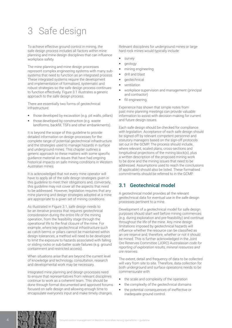
3 Safe designTo achieve effective ground control in mining, the safe design process includes all factors within mine planning and mine design disciplines that can influence workplace safety.
The mine planning and mine design processes represent complex engineering systems with many sub-systems that need to function as an integrated process. These integrated systems require the development and implementation of formalised, systematic and robust strategies so the safe design process continues to function effectively. Figure 3.1 illustrates a generic approach to the safe design process.
There are essentially two forms of geotechnical infrastructure:
• those developed by excavation (e.g. pit walls, pillars) • those developed by construction (e.g. waste
landforms, backfill, TSFs and other embankments).
It is beyond the scope of this guideline to provide detailed information on design processes for the complete range of potential geotechnical infrastructure and the strategies used to manage hazards in surface and underground mines. This chapter outlines a generic approach to these matters with some specific guidance material on issues that have had ongoing historical impacts on safe mining conditions in Western Australian mines.
It is acknowledged that not every mine operator will have to apply all of the safe design strategies given in this guideline to meet their obligations and, conversely, this guideline may not cover all the aspects that need to be addressed. However, legislation requires that any mine planning and design strategies adopted at a mine are appropriate to a given set of mining conditions.
As illustrated in Figure 3.1, safe design needs to be an iterative process that requires geotechnical consideration during the entire life of the mining operation, from the feasibility stage through the operational life to the final closure of the mine. For example, where key geotechnical infrastructure such as catch berms or pillars cannot be maintained within design tolerances, a method will need to be developed to limit the exposure to hazards associated with falling or sliding rocks or sub-batter scale failures (e.g. ground containment and restricted access).
When situations arise that are beyond the current level of knowledge and technology, consultation, research and developmental work may be necessary.
Integrated mine planning and design processes need to ensure that representatives from relevant disciplines continue to work as a coherent team. This should be done through formal documented and approved forums focused on safe design and allowing enough time to encapsulate everyone’s input and make timely changes.
Relevant disciplines for underground mines or large hard rock mines would typically include:
• survey • geology • mining engineering • drill and blast • geotechnical • ventilation • workplace supervision and management (principal
and contractor) • fill engineering.
Experience has shown that simple notes from past mine planning meetings can provide valuable information to assist with decision-making for current and future design issues.
Each safe design should be checked for compliance with legislation. Acceptance of each safe design should be signed off by relevant competent personnel and statutory managers based on the sign-off protocols set out in the GCMP. The process should include, where relevant, scaled plans, cross-sections and longitudinal projections of the mining block(s), plus a written description of the proposed mining work to be done and the mining issues that need to be addressed. Assumptions used to reach the conclusions (if applicable) should also be listed. These formalised commitments should be referred to in the GCMP.
3.1 Geotechnical modelA geotechnical model provides all the relevant geotechnical data for eventual use in the safe design processes pertinent to a mine.
Development of a geotechnical model for safe design purposes should start well before mining commences (e.g. during exploration and pre-feasibility) and continue throughout the life of the mine. Any mine design limitations imposed by geotechnical hazards will influence whether the resource can be classified as an ore reserve and, therefore, whether or not it should be mined. This is further acknowledged in the Joint Ore Reserves Committee (JORC) Australasian code for reporting of exploration results, mineral resources and ore reserves.
The extent, detail and frequency of data to be collected will vary from site to site. Therefore, data collection for both underground and surface operations needs to be commensurate with:
• the scale and complexity of the operation • the complexity of the geotechnical domains • the potential consequences of ineffective or
inadequate ground control.
Ground control management in Western Australian mining operations – guideline 5
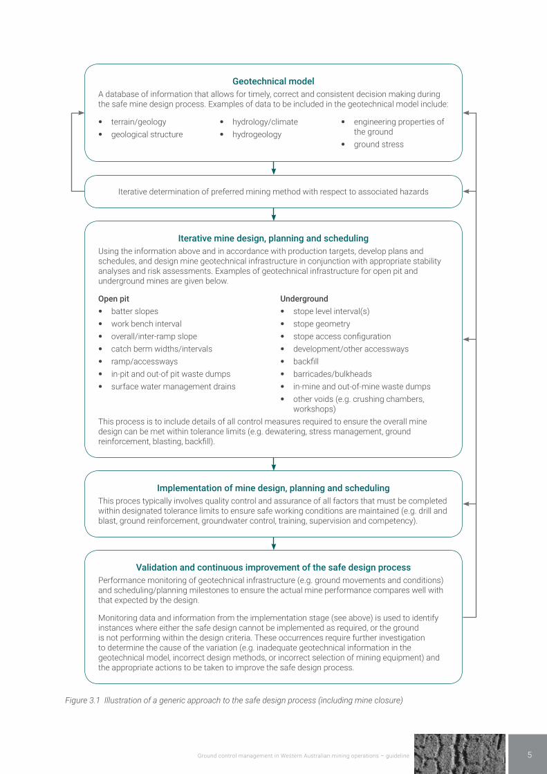
Geotechnical modelA database of information that allows for timely, correct and consistent decision making during the safe mine design process. Examples of data to be included in the geotechnical model include:
• terrain/geology • geological structure
• hydrology/climate • hydrogeology
• engineering properties of the ground
• ground stress
Iterative determination of preferred mining method with respect to associated hazards
Iterative mine design, planning and schedulingUsing the information above and in accordance with production targets, develop plans and schedules, and design mine geotechnical infrastructure in conjunction with appropriate stability analyses and risk assessments. Examples of geotechnical infrastructure for open pit and underground mines are given below.
Open pit • batter slopes • work bench interval • overall/inter-ramp slope • catch berm widths/intervals • ramp/accessways • in-pit and out-of pit waste dumps • surface water management drains
Underground • stope level interval(s) • stope geometry • stope access configuration • development/other accessways • backfill • barricades/bulkheads • in-mine and out-of-mine waste dumps • other voids (e.g. crushing chambers,
workshops)This process is to include details of all control measures required to ensure the overall mine design can be met within tolerance limits (e.g. dewatering, stress management, ground reinforcement, blasting, backfill).
Implementation of mine design, planning and schedulingThis proces typically involves quality control and assurance of all factors that must be completed within designated tolerance limits to ensure safe working conditions are maintained (e.g. drill and blast, ground reinforcement, groundwater control, training, supervision and competency).
Validation and continuous improvement of the safe design processPerformance monitoring of geotechnical infrastructure (e.g. ground movements and conditions) and scheduling/planning milestones to ensure the actual mine performance compares well with that expected by the design.
Monitoring data and information from the implementation stage (see above) is used to identify instances where either the safe design cannot be implemented as required, or the ground is not performing within the design criteria. These occurrences require further investigation to determine the cause of the variation (e.g. inadequate geotechnical information in the geotechnical model, incorrect design methods, or incorrect selection of mining equipment) and the appropriate actions to be taken to improve the safe design process.
Figure 3.1 Illustration of a generic approach to the safe design process (including mine closure)

Ground control management in Western Australian mining operations – guideline6
For example, the operator of small sand pits with homogenous materials would not be required to establish blasting procedures, undertake extensive exploratory drilling programmes, or conduct regular mapping of geological structure.
Data required to develop a geotechnical model can be obtained in several ways and can be both descriptive or observational and measurable or quantifiable.
The quality and usefulness of these sources of data for planning and safe design purposes can vary widely. However, even qualitative information is better than none and, if nothing else, such data can be used to identify the areas requiring more detailed investigation and analysis.
Potential data sources to consider prior to commencement of mining include:
• published literature • natural outcrops • existing local or neighbouring surface and
underground excavations • core drilling and, to a lesser extent, chip drilling logs
and geotechnical samples • trial pits or costeans • geophysical, geochemical and seismic surveys • pump and field tests.
Prior to mining commencing in larger mines, much of this data is sourced from geotechnically logged diamond cored boreholes as soon as the core becomes available and before being stored or split for assay determination. Geotechnical data from core that has not been photographed in its undisturbed state, was obtained after being split, or has not been adequately stored or oriented, has limited reliability.
Regardless of the methods of geotechnical investigation used and the actual number of holes geotechnically logged, it is fundamental that the information obtained for the geotechnical model:
• constitutes a suitably representative sample of the variability of actual ground conditions within the mineable deposit
• is suited to the mine planning and design process.
During operation of a mine, there should be ongoing review and updating of the geotechnical model (database). This ongoing assessment is required because of the relative paucity of data that is usually available for safe design in the early stages of mining.
Examples of works to validate the geotechnical model include:
• identifying the geotechnical domains in the ground mass (e.g. rock mass ratings) throughout the mine
• geotechnical scanlining or window sampling in selected areas of the mine, in three dimensions, to enable changes to existing geotechnical domains to be quantified in a timely manner
• checking baseline geological data against additional oriented core or geophysical logging
• improving knowledge of in situ engineering properties and groundwater characteristics by collecting and testing representative samples of ground and groundwater from within the mine to determine relevant engineering properties and groundwater characteristics
• comparing observed and measured ground performance against expected performance (e.g. through installation and use of ground stress and seismic monitoring devices)
• collating observations of local weathering to establish trends.
Geotechnical model development
As discussed in Section 3.1, the geotechnical model must be representative of the areas to be mined and pertinent to the planning and design processes to be implemented at a mine.
There is much literature available that illustrates preferred approaches to the development of geotechnical models over time (see Table 3.1). Competent persons need to undertake adequate research of this literature to establish which approach or approaches are best suited to their local conditions. They should understand the need to continuously improve the degree of confidence in the mine’s geotechnical models and thereby the final mine design.

Ground control management in Western Australian mining operations – guideline 7
Table 3.1 Example of data confidence target levels by project stage
Project stage
Project level status
Conceptual Pre-feasibility Feasibility Design and construction
Operations
Geotechnical level status
Level 1 Level 2 Level 3 Level 4 Level 5
Geotechnical characterisation
Pertinent regional information
Assessment and compilation of initial mine scale geotechnical data
Ongoing assessment and compilation of all new mine scale geotechnical data
Refinement of geotechnical database and 3D model
Ongoing maintenance of geotechnical database and 3D model
Target levels of data confidence for each model
Geology >50% 50-70% 65-85% 80-90% >90%
Structural >20% 40-50% 45-70% 60-75% >75%
Hydrogeological >20% 30-50% 40-65% 60-75% >75%
Rock mass >30% 40-65% 60-75% 70-80% >80%
Geotechnical >30% 40-60% 50-75% 65-85% >80%
From Read, J., and Stacey, P. (eds) (2009), Guidelines for Open Pit Design. CSIRO Publishing, Melbourne.
For larger, more complex mines, a geotechnical model will commonly include details on the following issues.
Ground surface related issues (hydrology, climate and terrain)
Surface water hydrology, if not adequately managed, can have a significant effect on geotechnical infrastructure and safe mining conditions. The extent of influence will depend on local site characteristics, the type of mine and mining methods used. For example, open pit and underground mines that intercept significant natural drainage paths or water storages can flood rapidly, or develop high water pressures in geotechnical infrastructure.
Where hydrological features can be influenced by mining (or vice versa), the safety of any other person travelling on the surface near to mining activities needs to be considered.
Consequently, a hydrological model needs to be developed, even if only to confirm the mine cannot be significantly impacted by surface water flows. A hydrological model will typically cover parameters such as:
• catchments, runoff characteristics and local drainage patterns (natural and created by mining activities)
• permanent and intermittent water bodies (natural and constructed)
• seasonal and extreme rainfall events • local evaporation rates.
Hazardous ground movements do not necessarily involve large volumes of water. For example, small volumes of rainwater that persistently pond behind
catch berms due to inadequate gradients along the berm can have a significant impact on ground control.
Terrain and topography will have a greater influence on open pit mines; however, issues such as safe access and potential variation in vertical loading can also impact underground mines.
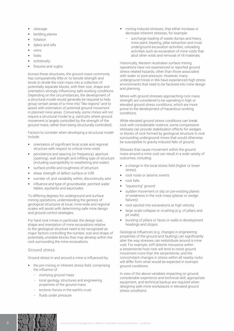
Geology and geological structure
The importance of the geological environment and geological structure and its potential for adverse influence on rock stability cannot be over-emphasised. Mine geologists, geotechnical engineers, mining engineers, supervisors and the underground workforce should recognise that geological influences, on a scale from less than a metre to hundreds of metres, are a major factor in most falls of ground in surface and underground mines.
Geological influences typically include:
• collapses bounded by bedding, a geological structure or both
• lithology of the orebody and host rock • orebody geometry • mineralisation and its impacts on ground
stabilisation elements • weathering and erodibility.
Geological structure refers to the natural planes or zones of weakness in the ground that pre-date any mining activity, including:
• joints • faults • shears
Ground control management in Western Australian mining operations – guideline8
• cleavage • bedding planes • foliation • dykes and sills • veins • folds • schistosity • fissures and vughs.
Across these structures, the ground mass commonly has comparatively little or no tensile strength and tends to divide the rock mass into a collection of potentially separate blocks, with their size, shape and orientation strongly influencing safe working conditions. Depending on the circumstances, the development of a structural model would generally be required to help group certain areas of a mine into “like regions” and to assist with estimation of potential ground movement in planned mine areas. Conversely, some mines will not require a structural model (e.g. sand pits where ground movement is largely controlled by the strength of the ground mass, rather than being structurally controlled).
Factors to consider when developing a structural model include:
• orientation of significant local scale and regional structure with respect to critical mine voids
• persistence and spacing (or frequency), aperture (opening), wall strength and infilling type of structure (including susceptibility to weathering and water)
• surface profile and roughness of structure • shear strength of defect surface or infill • number of, and variability within, discontinuity sets • influence and type of groundwater, perched water
tables, aquitards and aquicludes.
To differing degrees for underground and surface mining operations, understanding the genesis of geological structures at local, mine-wide and regional scales will assist with determining safe mine design and ground control strategies.
For hard rock mines in particular, the design size, shape and orientation of mine excavations relative to the geological structure need to be recognised as major factors controlling the number, size and shape of potentially unstable blocks that may develop within the rock surrounding the mine excavations.
Ground stress
Ground stress in and around a mine is influenced by:
• the pre-mining or inherent stress field, comprising the influence of
– overlying ground mass – local geology, structures and engineering
properties of the ground mass – tectonic forces in the earth’s crust – fluids under pressure
• mining-induced stresses, that either increase or decrease inherent stresses, for example:
– surcharge loading of waste dumps and heavy mine plant; blasting, pillar extraction and most underground excavation activities; unloading activities such as excavation of mine voids that abut other voids and removal of rill materials.
Historically, Western Australian surface mining operations have not experienced or reported ground stress-related hazards, other than those associated with water or pore pressure. However, many underground mines in WA have experienced high stress environments that need to be factored into mine design and planning.
Mines with ground stresses approaching rock mass strength are considered to be operating in high or elevated ground stress conditions, which are more prone to the development of hazardous working conditions.
While elevated ground stress conditions can break rock with considerable violence, some compressive stresses can provide stabilisation effects for wedges or blocks of rock formed by geological structure in rock surrounding underground mines that would otherwise be susceptible to gravity-induced falls of ground.
Stresses that cause movement within the ground mass around a mine void can result in a wide variety of outcomes, including:
• a change in the local stress field (higher or lower stress)
• rock noise or seismic events • rock falls • “squeezing” ground • sudden movement or slip on pre-existing planes
of weakness in the rock mass (planar or wedge failures)
• rock ejected into excavations at high velocity • large scale collapse or crushing (e.g. of pillars and
pit walls) • bursting of pillars or faces or walls in development
headings and stopes.
Geological influences (e.g. changes in engineering properties of the ground and faulting) can significantly alter the way stresses can redistribute around a mine void. For example, stiff dolerite intrusions within a serpentenite host rock will tend to resist ground movement more than the serpentenite, and the concomitant changes in stress within all nearby rocks will differ from what would be expected in isotropic ground conditions.
In view of the above variables impacting on ground, considerable experience and technical skill, appropriate equipment, and technical backup are required when designing safe mine workplaces in elevated ground stress conditions.

Ground control management in Western Australian mining operations – guideline 9
Consequently, the mine operator needs to recognise and quantify the potential for any changes in stress (or loading) during the life of the mine from an early stage, and use suitable methods and tools for predicting the likely outcomes.
Hydrogeology
The hydrogeological environment can significantly affect the stability of geotechnical infrastructure and safety of mining operations. The impact is greater in mines where the expected failure mechanisms are more influenced by water pressure (e.g. interstitial pore water pressure in soft rock and soil) or where groundwater quality impacts on the integrity of any ground support and reinforcement being used to stabilise the mine.
To understand the hydrogeological conditions at a mine site, adequate investigation should be undertaken prior to and following the commencement of mining.
Early recognition of the potential for groundwater issues will allow for better use of exploration drill holes as piezometers or production bores.
Furthermore, as open pit wall failures often occur after rain, it may be necessary to develop an understanding of the time-lag and mechanisms of infiltration of surface water into the ground mass. Underground mines are not exempt from this type of relationship.
The approach to groundwater control can be divided into two general categories:
• water abstraction in advance of mining (e.g. in-pit and out-of-pit production bores)
• water abstraction during mining (e.g. sumping, production holes drilled into the mine, and subhorizontal holes drilled into mine abutments).
Each method can be used individually or in combination to produce the required outcome. Selection of the most appropriate depressurisation method will depend largely on the local and regional hydrogeological conditions, the potential impact of unwanted outcomes on the mine, and the required rate of mining.
A competent person should develop and maintain a hydrogeological database to help evaluate the characteristics of regional and local aquifer systems and thereby assist with determining factors such as:
• zones of hydrological influence • relationship between groundwater, lithology and
geological structures • recharge mechanisms and the required rate
and scheduling of groundwater abstraction (i.e. withdrawal) and relevant monitoring strategies
• potential impacts of groundwater on ground movement (e.g. interstitial pore-water pressure, undercutting, chemical degradation, swelling clays) and backfill materials
• the potential impact of mine dewatering or depressurisation on local drainage systems
• the potential for groundwater corrosion of any ground support and reinforcement
• the potential for any unsealed drill holes to intercept aquifers or water-filled voids
• the potential for any water-filled voids (e.g. old mine workings) to influence the mine hydrogeological model.
Note: Inundation is recognised as a principal hazard and requires its own management plan. This plan should be referred to in the GCMP.
Engineering properties
The extent to which ground is expected to move towards a mine void primarily depends on the engineering properties of the ground mass under given stress or loading conditions. Examples of the potential range of ground movements include small-scale elastic relaxation, plastic squeezing of the ground, and brittle failure causing ground ejection.
To determine the engineering properties relevant for safe design at a specific mine, the competent person therefore needs to understand the:
• likely loading conditions (both natural and mining-induced)
• potential movement and failure mechanisms of the ground under the likely loading conditions.
Engineering properties are commonly derived by various tests on samples of ground; however, back analysis of ground movements is another reliable method when the correct failure mechanism is known. With respect to laboratory testing, published recognised testing procedures are readily available to determine relevant engineering properties (e.g. ASTM, ISRM).
Indirect testing methods (e.g. point load tests and cone penetrometer) can be used to estimate some engineering properties where appropriate. Index test results that have been calibrated against recognised laboratory test results are more reliable for use in the safe design process.
Examples of common engineering properties to be evaluated and used for safe design include:
• unconfined compressive strength • uniaxial tensile strength • elastic modulus • Poisson’s ratio • shear strength • bearing capacity • bulk density • plasticity • porosity • moisture content • permeability • slake durability • linear shrinkage, swelling

Ground control management in Western Australian mining operations – guideline10
• creep • P and S wave velocity.
In some instances, it may be necessary to undertake specialised testing, such as post-peak testing, to estimate the post-failure strengths of ground to be mined (e.g. residual shear strength for “crush pillars” in an underground mine).
The engineering properties can be a challenge to quantify due to complex interactions between factors such as:
• intact rock strength • influence of geological structures (e.g. orientation,
persistence, spacing and shear strength parameters) on the ground mass
• presence of groundwater • scale effect between a sample of the ground and
the ground mass as a whole • alteration of minerals on exposure to air or water
with time.
One useful method to assess the impacts of unknown influences on engineering properties by such factors is back analysis of ground movements measured within the mine. This method estimates some of the engineering properties relevant to a geotechnical structure by analysing its behaviour under load. The method relies on instrumentation to determine, directly or by calculation, changes in displacements, strains, pressures and stresses during mining. This approach generally requires a good knowledge of the geometry of the geotechnical infrastructure, stress field, mode of failure and use of appropriate geotechnical model(s) for success. The best results are achieved when baseline monitoring results are available before ground movement commences.
Consequently, the responsible person should ensure the following aspects are specified in the GCMP:
• laboratory testing requirements for mine design purposes
• the number of ground specimen tests required to provide statistical correctness and an adequate representation of the ground to be mined
• the limitations and implications for use of all testing methods and use of the data from these tests for the safe design process.
Geotechnical domains
The data collated within the geotechnical model is typically used in two ways:
• for direct input into engineering design methods • to divide the ground mass into groups or domains of
similar attributes and expected behaviour.
Examples of geotechnical domains include:
• weathering zones
• rock stress field and zones of high or low stress (pre-mining and mining-induced stress fields)
• orientation of major geological structure with mine void geometry
• ground lithology • intact rock uniaxial compressive strength • deformation modulus of the rock mass • hydraulic conductivity of the ground • zones of ground that are affected by groundwater or
water pressure • ground classification (e.g. RMR, Q, MRMR, GSI, SMR,
traffickability, excavatability, ISRM).
Geotechnical domaining is also a useful method to identify specific areas of the mine that may require specific attention or modification to a standard design. These particular areas can be referred to as design sectors where different methodology is to be implemented to ensure the provision of safe workplaces for the duration of the mine.
The procedure used for data collection and analysis for interpretation of domains should form part of the GCMP.
3.2 Mine design, planning and schedulingIt is reiterated that mine design, planning and scheduling issues not related to the provision of effective ground control (with respect to legislative requirements in mine safety) are not covered in this guideline.
Mining methods and equipment
Before a mine commences and commitment is made to the development of accesses or bench ramps to various orebodies and a particular mining method, the mine operator needs to establish a sound understanding of local ground conditions. In open pit mines, the choice of mining method and equipment generally has far less impact on the safe working environment than underground mines.
For underground mines, one of the first decisions is whether to use “re-entry” or “non-entry” stoping methods. Re-entry stoping methods include cut and fill, room or bord and pillar, gallery stoping and shrinkage stoping. They have the common feature that the workforce is exposed to the potential hazard of rock falls from, or collapse of, large areas of stope backs and walls, particularly in wide orebodies. Re-entry methods require successive slices or lifts to be mined from the orebody, and hence the need to scale loose rock and install ground support each lift. These mining methods therefore require a high level of effort in local-scale ground control; however, benefits usually include better ore grade control, minimising dilution and maximising recovery.

Ground control management in Western Australian mining operations – guideline 11
Non-entry stoping methods include open stoping, sub-level caving and block caving. These mining methods require a much higher level of technical input into large-scale ground control, primarily because of the large dimensions of the stopes or the area being excavated and the potential for rapid and significant changes in ground stress.
Non-entry stoping systems are more suited to mass blasting techniques than re-entry stoping systems. Large, sudden changes in void geometry by mass blasting can cause large-scale ground movements into nearby mine openings, causing access or air-blast problems, ore dilution and damage to drawpoints. Conversely, sub-level and block caving methods may hang-up or not cave in a controlled manner, causing significant hazard and safety concerns.
Mining equipment should be fit for purpose and capable of meeting the mine design requirements. For example, jumbo drills, where used in development drives, need to be capable of installing reinforcement at the correct spacing and orientation without being restricted by confined work spaces. Similarly, equipment used to scale loose material from batter crests in open pits after blasting should be able to safely access the crests and achieve the standard required.
Comprehensive risk assessments should be used to determine the most appropriate mine method and associated plans and scheduling.
The importance of involving competent personnel in such risk assessments without undue influence from production pressures cannot be overstated. Historically, risk assessments have not worked well in the mining industry when assessing the potential for isolated rocks to fall and result in serious injury or death. Two examples include the reliance on spot-bolting in underground mines and the use of manual scaling and drilling while hanging off ropes in large open pit mines. In the first instance, a number of fatalities in the mid-1990s required the introduction of the Department’s Surface rock support for underground mines – code of practice. This code of practice specifies that all re-entry voids more than 3.5 metres in height should have surface ground support. Sites that don’t follow this general rule need to justify why surface support is not required, and explain the management strategies to be adopted to prevent exposure to these hazards (e.g. systematic check scaling).
Sequencing and scheduling
In simple terms, sequencing and scheduling in open pit and underground mines involves:
• providing safe access to ore • providing safe ore extraction • enabling safe and sustainable mine closure.
Sequencing and scheduling of areas to be mined is a part of ground control that often does not get adequate recognition. Inappropriate sequencing and scheduling generally results in one of two issues:
• unsafe workplace setups • unsafe ground conditions.
Hazardous workplace setups usually involve working in confined areas, or unnecessarily working near other hazards such as drop-offs or unsupported or potentially unstable ground.
Examples of associated unsafe ground conditions include:
• unfavourable mine shapes or “pendants” of ground • undesirable locations for waste disposal • adverse high or low stress levels due to void
geometry (mostly applicable to pillars, abutments and remnants in underground mines)
• adverse stress levels due to rapid rates of lateral advancement or increase in depth; such as mines in soft ground below the ground water table, where high pore pressures can develop.
Attendant problems such as blast hole closure in high stress environments or ravelling of the stope walls in a low stress environment also present problematical issues resulting from inadequate sequencing and scheduling.
These types of hazards are readily avoided with the implementation of sound mine planning strategies.
Geotechnical controls associated with short and long term voids can vary significantly. Hence mining schedules should be developed for key issues where relevant (e.g. pit ramp or decline designs and location, areas requiring ground support and reinforcement, stope extraction and filling sequences, and pillar formation) for a range of timeframes during the mine life.
In addition, mines can have a variety of void types (e.g. underground mine workshops and access ways for the movement of people, air, ore and waste rock). Each can require different ground control management strategies that need to be planned for in advance of their development.
Mine operators relying on sequential approvals or releases of land from local municipalities or corporate bodies should ensure mine scheduling can accommodate process delays.
A life of mine (LOM) production schedule presenting an overview of mine development and production requirements for the total life of the mine should also be available. This schedule should highlight, for example, the formation of permanent and recoverable crown or rib pillars, propose pillar recovery sequences, access requirements and suggest possible mining methods for the recovery of non-permanent pillars.
Ground control management in Western Australian mining operations – guideline12
Mine layout and support system trials can be an effective way for gathering evidence as to the suitability of a proposed design strategy for the prevailing rock mass and stress conditions
3.3 Design methods Numerous design tools and methods are available to help mine operators maintain effective ground control. These design methods are commonly divided into groups of similar types or mechanisms of design, such as those described below.
Safe mine design requires a good understanding of the limitations associated with the use of any particular design method, and the circumstances under which the method can be applied.
Considerable engineering judgement and mining experience are required to determine the appropriate level of analysis for the design of geotechnical infrastructure.
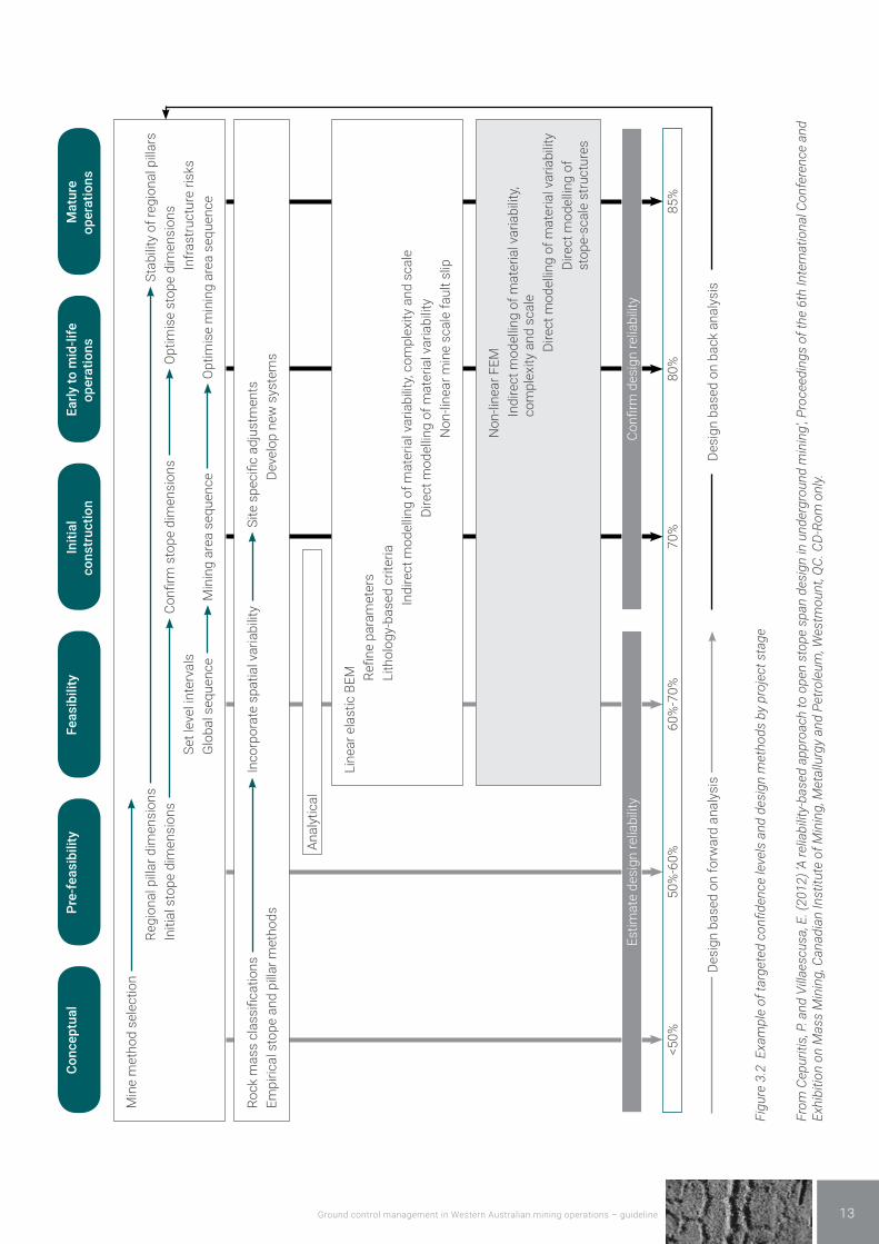
In addition, some design methods are better suited for initial planning and early stages of mining than others. The level of design certainty should improve over time, commensurate with the hazards at a mine. Figure 3.2 shows how various design methods can be used during the life of a mine .
Note: Figure 3.2 is provided for illustration purposes only. Each mining operation will have priorities that can have significant impacts on such targets.
Empirical methods and rules of thumb
These methods allow mining experience in a particular set of ground conditions to be incorporated into the mine design process. Empirical methods for mining and tunnelling often use rock mass classification methods, or a modified version thereof, to relate the mine void geometry to the expected ground conditions. Examples include the tunnelling index, MRMR, Q, Q’, coal mine roof rating relating to hydraulic radius (HR), and span and ground support. Rules of thumb (such as pillar width to height ratios, or rock bolt length) are purely experience based.
These methods have many limitations, mainly because they are an averaging process. For example, the inherent variability of the rock mass can be obscured by the need to make it conform to an arbitrary set of tabulated numbers.
Safe designs obtained using these methods may need to be cross-checked by more refined design methods where input data, such as mine geometry, are more complex, and will require regular and rigorous performance monitoring strategies for continued use.
Notwithstanding these limitations, empirical design methods can be a useful tool, particularly early in the mine life.
Kinematic, analytical, deterministic or probabilistic methods
These methods are best used with geotechnical parameters derived from in-mine measurement, laboratory testing or back analysis of existing failures (and recorded in the geological or structural section of the GCMP). Examples of the tools available within these methods include beam theory, voussoir arch and Janbu method of slices. They typically pertain to specific sections of the mine. These methods are prone to error when other factors, such as nearby mine voids and variable geology, can influence ground performance. However, they are relatively quick and easy to use for simple assessment of mining options in certain locations.
Safe designs obtained by these methods should be verified by regular mapping of site-specific data and require regular performance monitoring strategies throughout the life of the mine.
Numerical modelling codes
Numerical methods of stress analysis or block behaviour, in two or three dimensions, can allow for the interaction of nearby mine voids and geological variation to be considered in much more detail than is the case with empirical design methods. The use of numerical methods generally requires considerably more input data, including the geometry and sequencing of development openings, open pit walls, stopes and pillars, in situ stresses, engineering properties of the ground mass, and location and orientation of geological structure. Numerous different numerical modelling codes and programs exist, each with their unique strengths and weaknesses. The use of a numerical stress analysis method, without knowing its weaknesses, stress measurements and limitations, can be problematic.
Examples of issues associated with these modelling codes include:
• lack of calibration • lack of representative input data and overreliance on
output • the use of simplistic elastic strain methods for mine
design problems that involve rock failure, dilation or large scale strain
• insufficient representation of the actual mine geometry being analysed (e.g. complex 3D geometry being poorly approximated by a 2D cross-section)
• inability of codes to represent the inherent variability of the actual geological and ground mass conditions
• modellers having inadequate experience to correctly interpret the results in the context of actual underground or open pit observations.
Ground control management in Western Australian mining operations – guideline 13
Conc
eptu
alea
sibi
lity
e-f
PrFe
asib
ility
Initi
al
cons
truc
tion
o m
id-li
fe
atio
nsEa
rly t
oper
e at
ions
Mat
urop
er
e ris
ksas
truct
urIn
fral
sv
el in
ter
vSe
t le
Min
e m
etho
d se
lect
ion
egio
nal p
illar
sSt
abili
ty o
f rRe
gion
al p
illar
dim
ensi
ons
ea s
eque
nce
Opt
imis
e m
inin
g ar
ea s
eque
nce
Min
ing
arG
loba
l seq
uenc
e
ope
dim
ensi
ons
Opt
imis
e st
ope
dim
ensi
ons
Confi
rm s
top
e di
men
sion
sIn
itial
st
Site
spe
cific
adj
ustm
ents
elop
new
sys
tem
sv
Dear
iabi
lity
ate
spat
ial v
Inco
rpor
ope
and
pilla
r met
hods
Rock
mas
s cl
assi
ficat
ions
Empi
rical
st
Anal
ytic
al
, com
plex
ity a
nd s
cale
aria
bilit
yar
iabi
lity
Non
-line
ar m
ine
scal
e fa
ult s
lipec
t mod
ellin
g of
mat
eria
l vIn
dire
ct m
odel
ling
of m
ater
ial v
Dir
amet
ers
Refin
e pa
rLi
thol
ogy-
base
d cr
iteria
Line
ar e
last
ic B
EM
aria
bilit
y
es
aria
bilit
y,
ect m
odel
ling
of m
ater
ial v
ect m
odel
ling
of
ect m
odel
ling
of m
ater
ial v
Dir
stop
e-sc
ale
stru
ctur
Non
-line
ar F
EM
com
plex
ity a
nd s
cale
Dir
Indi
r
elia
bilit
yCo
nfirm
des
ign
rel
iabi
lity
Estim
ate
desi
gn r
85%
80%
70%
60%
-70%
50%
-60%
<50%
d an
alys
isw
arDe
sign
bas
ed o
n fo
rDe
sign
bas
ed o
n ba
ck a
naly
sis
Figu
re 3
.2 E
xam
ple
of ta
rget
ed c
onfid
ence
leve
ls a
nd d
esig
n m
etho
ds b
y pr
ojec
t sta
ge
From
Cep
uriti
s, P
. and
Vill
aesc
usa,
E. (
2012
) ‘A
relia
bilit
y-ba
sed
appr
oach
to o
pen
stop
e sp
an d
esig
n in
und
ergr
ound
min
ing’
, Pro
ceed
ings
of t
he 6
th In
tern
atio
nal C
onfe
renc
e an
d Ex
hibi
tion
on M
ass
Min
ing,
Can
adia
n In
stitu
te o
f Min
ing,
Met
allu
rgy
and
Petro
leum
, Wes
tmou
nt, Q
C. C
D-Ro
m o
nly.

Ground control management in Western Australian mining operations – guideline14
While acknowledging the potential problems with numerical modelling, a significant benefit of these design methods is their use for comparing various mining strategies (e.g. alternative extraction sequences).
For continued use, safe designs obtained by these methods should be regularly verified by calibrating performance monitoring data with model output.
Physical modelling
This method is not often used in Australia. Scaled models of the mine or part of the mine are constructed to assess potential ground behaviour for various mining strategies. The models are constructed in such a way that all the relevant parameters (e.g. mine void dimensions, depth or loading conditions, engineering properties) are proportionally scaled (e.g. using the dimensionless Buckingham Pi theory).
These models are typically applied to one-use projects when the mining proposal does not exist, or to test a theory (e.g. mining subsidence in weak sediments). There is usually limited or no ongoing use of this design method.
3.4 Design acceptance criteria and design eventsDesign acceptance criteria for various mining practices should be adopted that reflect the level of uncertainty and the perceived risks in each area of the mine. For example, more conservative or risk-averse planning and design strategies need to be adopted at mines that may have:
• limited geotechnical information (not statistically representative)
• limited knowledge of ground control management • limited ability (financially or otherwise) to suitably
manage ground movements • the potential for sudden falls of ground that can
harm many personnel • significantly variable ground or mine conditions • important geotechnical or other infrastructure
(mine-related or public) nearby.
Common criteria used to quantify the level of conservatism in any design include factor of safety (FOS) and probability of failure (POF). Table 3.2 provides an example of an approach for FOS design acceptance criteria.
Each geotechnical design criteria relies, in different ways, on some form of design event (e.g. flood, earthquake). Other forms of design event consideration are the use of worst-case, average or median engineering properties, or potential block or wedge size for specific design methods.
Table 3.2 Example of design criteria using FOS
Consequence of failure
Design FOS Geotechnical infrastructure examples
Not serious Not relevant Ground (not carrying major infrastructure) where all expected potential failures can be contained within containment structures.
Moderately serious 1.2 Ground that has some potential for interaction with the workforce if safe operating procedures are not well followed.
Serious or long term 1.5 Ground carrying major mine infrastructure (e.g. TSF, main ramp) or has potential for large scale failure into workplaces; mine closure slopes that do not comply with the generic design angles provided in the Department’s Safety bund walls around abandoned open pit mines – guideline.
Note: The guideline design angles for open pit closure are 45 degrees through fresh rock and 25 degrees through weathered rock (with a 10 metre wide buffer at the slope crest before the placement of an abandonment bund).
Extreme or long term 2.0 Permanent pit walls or unfilled stopes near the surface that can impact on public infrastructure or land owned by other person(s) after mine closure.
Note: The use of one design approach and factor of safety over another will largely depend on the local ground conditions, the potential modes of failure, the amount, quality and variability of information available or obtainable and the likely worst case outcome. Any design criteria used must be verified and validated against these factors.
Ground control management in Western Australian mining operations – guideline 15
As illustrated in Table 3.2, selecting the most appropriate design events involves an assessment of the hazard, potential outcomes, and corresponding risks.
Design acceptance criteria, design event criteria and risk assessment should also consider impacts from:
• ground conditions changing during the life of the mine
• design assumptions made for various design-influencing factors such as:
– loosening of the rock mass due to blast or seismic vibrations
– alteration of properties of some rocks on exposure to air or water over time (e.g. slaking, pore water pressure variations)
– variable time-dependent behaviour of rock mass under static loading
– quality of excavation and sudden changes in void geometry (e.g. poor blasting, formation of a “bull-nose” promontory along the wall)
– localised variation in stress (e.g. stress reduction or increase in pit walls or underground voids, abutments and pillars associated with large underground stopes)
– surcharge loading (e.g. waste dumps close to pit crests, loaded haul trucks near to tip heads).
The potential negative impact of using assumed variables that are not representative of the actual ground conditions for safe mine design can be significant. Ideally, sensitivity analyses should be conducted to determine the effect of “uncertainty” for both the design assumptions being used and the various geotechnical design methods being used.
The basis for adopting any design method, strategy, and design acceptance criteria needs to be formally justified and documented in the GCMP. Any assumptions made for this justification should also be included in the GCMP. Conversely, if the samples of ground used for engineering property testing are not representative of the full range of geotechnical materials to be mined (e.g. only the best drill core recovered is tested), then higher factors of safety should be adopted for the mine design criteria.
The practices used at a mine need to be verified and validated by formal review processes.
Where validation and verification processes identify potential issues of concern, additional work should be undertaken to:
• remedy these matters (e.g. improve the geotechnical database by testing statistically acceptable numbers of undisturbed samples of ground to obtain a better understanding of the ground mass)
• limit the use of the specific method (e.g. limit the use of two-dimensional simplifications for complex three-dimensional mine void geometries)
• use other design or modelling techniques that can augment each other, or develop a new or modified method using site-specific data.
3.5 Mine closure Before mines can be legally closed, the Department requires that long-term environmental performance and public safety have been considered and managed appropriately. Hazards that may need to be controlled include:
• rockfalls (e.g. wall failure, pillar and roof collapses leading to surface subsidence)
• fall from height (e.g. hidden vertical shafts and edges of pit walls)
• flooding or inundation (e.g. surface drainage, dam embankment failure, weather events).
In the final stages of mining, the geotechnical design should have sufficient data to demonstrate that the long-term issues associated with closure and rehabilitation of a mine can be adequately controlled. Mines located beneath or adjacent to important public or mine infrastructure will require more conservative and detailed design acceptance criteria for long-term stability (see Table 3.2) and need to be supported by acceptable monitoring information.
Guidance material to prevent inadvertent access to open pit mines is provided in the Department’s Safety bund walls around abandoned open pit mines – guideline.
Ground control management in Western Australian mining operations – guideline16
4 Safe design implementation and reviewDetails of the actions to be taken to ensure that safe mine planning and designs can be implemented within the standards and tolerances required should be formally documented. The documents should include safe work procedures, original equipment manufacturer’s (OEM’s) requirements and work instruction guidelines, and be listed in the GCMP.
The mine operator should conduct a verification review to confirm no requirements are missed in the mine design. For example, all the design inputs (e.g. specifications, government and industry regulations, industry experience, and any other factors necessary for the proper functioning of the mine) are compared against design outputs (e.g. design criteria, drawings, and assembly, installation and monitoring instructions).
If the review identifies areas where the design process does not meet with design intent, the design process needs to be changed and those changes reflected in the GCMP.
The mine operator should then undertake a practical validation review to help ensure that the geotechnical structure, as built, will function according to the requirements for the life of the mine and, if relevant, after closure.
The validation review process needs to include the learnings from failures as well as successes. The results of monitoring, inspections and audits (internal or third party) form part of the review process. Reviews should be conducted:
• on a regular basis (e.g. as part of a general audit) • after a significant unplanned event.
The matters to be considered for validation can be categorised into three types:
• The geotechnical model. For example, undertaking geological and geotechnical mapping of exposed surfaces, additional drilling, logging, testing and instrumentation to confirm all geotechnical assumptions. Back analyses of failure events and ground performance observations can also be undertaken to better define ground mass properties and behaviour.
• Mine planning and design processes. For example, monitoring the capacity of achieving the designed stope and slope configurations while minimising potential for seismic conditions; measuring the effectiveness of dewatering and depressurisation designs.
• General operational issues. For example, monitoring blast damage such as the degree of over-break of batter crests, stopes and development drives; measuring of as-excavated mine voids, batter face angle and berm width; efficiency and effectiveness of ground support and reinforcement installation; training and competency.
As a minimum, the mine operator is required to conduct visual workplace safety inspections before the commencement of each shift to assess potential safety issues, including those relating to ground control. However, it is expected that the frequency and nature of inspections will be appropriate for the rate of mining and potential hazardous outcomes at each location. For example, visual performance monitoring is commonly not sufficient for all types and mechanisms of ground movement as it may not provide adequate forewarning of imminent unsafe ground movements to enable timely remedial action. As a starting point, simple, robust monitoring equipment (e.g. survey pins or crack monitors), combined with regular recorded visual observations, is considered appropriate for most mines.
When designing the performance monitoring system, a competent person should take into account any limitations in monitoring methods (e.g. power supply, exposure to rockbursts, exposure to fly rock and competency of personnel) and requirements for site access.
Operationally, the immediate purpose of performance monitoring is to identify changes in exceptional ground mass behaviour that:
• requires immediate attention, including the withdrawal of personnel if necessary
• indicates that hazardous mining environments could develop if existing ground control management strategies are not amended.
Determining the timing and type of corrective actions (e.g. change in mine plan and design) in both scenarios will need to be in accord with the mine’s change management policies and will depend on factors such as:
• mine access • production and development scheduling • nature of the hazard and risk.
The monitoring strategies and operational responses to ground movement should be determined in accordance with the site’s change and hazard management processes. Trigger action response plans (TARPs) should be developed to ensure appropriate, timely actions are taken.
The TARPs should:
• have a clear purpose • address all potential outcomes resulting from all
relevant hazardous ground movements • be easy to understand, with clearly defined
performance monitoring strategies, triggers and actions to be taken
• be aligned with the philosophies adopted for site emergency action plans

Ground control management in Western Australian mining operations – guideline 17
• have clear roles and responsibilities for all relevant personnel
• be able to be executed by all relevant personnel • be readily available to all relevant personnel • have suitable training and awareness programmes
for personnel directly and indirectly associated with them.
Reviews of monitoring strategies and associated TARPs should also be undertaken whenever:
• ground conditions change • new systems of work are to be introduced • new plant and equipment are to be introduced that
may change the potential for exposure to hazards • new designs or mining methods are to be
introduced.
A review of previous production schedules and mining history can provide valuable insights as to why particular geotechnical problems may have developed, and whether the design process should be improved.

Ground control management in Western Australian mining operations – guideline18
5 Managing hazardous or potentially unstable ground5.1 Unstable groundUnplanned ground movements should be expected in all mines due to the inherent uncertainties within the geotechnical models, design methods and design implementation (e.g. installation of ground reinforcement). Consequently, all areas of the mine where personnel are expected to work or travel through need to be regularly inspected for potential hazardous ground movements. When loose rock or ground movement exceeds defined tolerance limits, formalised management activities need to be developed to safely remediate these locations.
Considerations for management strategies for loose rock that represents a hazard to mine workers include:
• barricading the area from inadvertent access (e.g. catch bunds are commonly used at the draw point of an open stope in an underground mine or at the toe of an open pit batter slope)
• conducting a risk assessment to assess the hazard control measures required to gain access to the affected area
• conducting an investigation of the causal factors of the unplanned ground movements
• establishing remedial measures to make the area safe, which may include changes to the mine designNote: Support strategies should then be identified and considered for the planning, design and implementation of the remedial measures (if the causal factors are not understood, the remedial measures implemented may not be adequate to prevent recurrence of similar events).
• updating the GCMP.
The risks involved when rehabilitating an area affected by hazardous ground movements are often greater and more complex than ground control tasks undertaken on a routine basis in a mine. Safe work procedures for rehabilitating destabilised areas should be developed to assure the safe and satisfactory completion of any remedial work, and change management policies should be followed.
A record should be kept of all unplanned ground movements, together with the causal factors identified, recommendations made following the incident investigation, and outcomes of the remedial work.
While the act of scaling is relatively straightforward, careful attention should be paid to the safe work procedures for the following:
• identifying the ground conditions • manual scaling • mechanised scaling • scaling of large potentially unstable blocks • scaling in ravelling ground • scaling in high or difficult to access areas.
Note: For further information on scaling, refer to the Department’s Mines Safety Bulletin No. 067. Open pit scaling and the Underground barring down and scaling guidelines.
In some instances, the volume of rock involved or type of movement is significant enough to require detailed investigation, reassessment of the safe mine design process and modification of the GCMP. Events of this nature should be considered on a case-by-case basis.
When large volumes of loose rock develop, the immediate action should be to barricade the area from inadvertent access using a safety or catch bund.
5.2 Mining through underground workingsMining through underground workings (by surface or underground operations) presents a number of potential hazards that need to be accounted for in the mine design. Examples of mine planning-related geotechnical issues to be investigated include the following:
• Determining the location and extent of the existing underground excavations (e.g. by probe drilling or remote sensing applications), the status of underground mine voids (e.g. whether they are filled or partially collapsed), and variations between the underground voids encountered in the base of the open pit and those shown in existing mine plans of the underground workings.
• Establishing accurate survey plans recording the location, spacing, depth, direction, angle and number of drill holes, as well as recording interpreted ground conditions during drilling. It is also important to denote locations where voids have been removed or filled during the mining process.

Ground control management in Western Australian mining operations – guideline 19
• Determining the safe thickness of “undisturbed” ground left between open active workplaces and underground workings for continued stability of the workplaces such that personnel and mining equipment can safely traverse during mining operations.
• Establishing a suite of operating procedures for mining near and through underground voids that match with production requirements. Matters to be covered include personnel and equipment access; blasting strategies; infill, backfill and barricading procedures; and general reporting procedures (particularly when new unstable ground is detected).
It is the responsibility of mine management to ensure that safe working procedures that address each of these issues are appropriate for the risks at each mine site and are implemented rigorously. The implementation of these procedures should be incorporated in the GCMP.
Further information is available in the Department’s Open pit mining through underground workings –guideline.
Ground control management in Western Australian mining operations – guideline20
6 Communication, training and supervision6.1 Communication and consultation processesFormal communication and consultation processes should be established between the mine operator and all personnel responsible for ensuring effective ground control at a mine. The potential for exposure to ground movement hazards substantially increases if:
• ground control hazards in workplaces are not identified by the general workforce
• ground conditions and ground control requirements are not well understood, and controls are not well designed
• ground control measures and designs (e.g. blasting and reinforcement designs) are not implemented appropriately
• the geotechnical knowledge base and GCMP are not kept up-to-date and made accessible for current and future mine personnel.
The communication strategy relevant to ground control should include the provision of information and instructions, such as:
• mine design and planning protocols • the use of risk assessment tools, such as job safety
or hazard analyses (JSAs or JHAs) • policies, procedures and standards, such as
standard operating procedures (SOPs) and safe work procedures (SWPs)
• requirements and specifications for ground support installation and ground monitoring (e.g. instrumentation, visual and aural observations)
• manuals and operating instructions provided by OEMs
• applicable legislation, Australian and industry standards, and other guidance material
• TARPs for managing ground movements beyond the site’s specified tolerance limits
• emergency response plan.
The communication process involves:
• including all information relevant to effective ground control within easy-to-access documents such as the GCMP
• providing hazard maps and monitoring data in easy-to-read formats on commonly accessed notice boards
• providing adequate training for all persons involved in the design, implementation and assessment processes
• implementing adequate supervision.
A comprehensive GCMP allows those responsible for mine planning and design to provide adequate and timely information to each person who has an impact on ground control, or who could be affected by ineffective or inadequate ground control. Typically, the GCMP specifies:
• each purpose for which the plant, substance or structure was designed
• the results of any calculations, analysis, testing or examination, including, in relation to a substance, any hazardous properties of the substance identified by testing
• any actions required to ensure that the plant, substance or infrastructure does not present unacceptable risks to the safety and health of personnel when carrying out mining activities.
Ideally, communication and consultation processes should recognise and address the downside as well as the upside of any practices or information used when planning and designing mines. Open discussion of all relevant practices, design methods, equipment, technology and the limitations of knowledge or data is central to sound geotechnical engineering practice. Those with knowledge and experience in ground control have a duty of care to inform their colleagues or client(s) of the inherent strengths and weaknesses of any preferred course of action in an objective and unbiased manner. Similarly, mine operators should make timely, balanced and documented decisions regarding the application of that knowledge, and ensure those decisions are promptly communicated to the relevant people and formally documented for future reference.
The GCMP should be structured to help identify and manage communication, training and supervision requirements at a mine.
6.2 Geotechnical hazard mapsA hazard map is a tool for visually conveying information to mine workers about current geotechnical hazards in the mine.
It is recommended that geotechnical hazard maps are generated and updated on regularly, and used to assist with:
• developing and scheduling workplace inspections • highlighting areas requiring careful consideration by
the workforce • developing site-specific TARPs and actions to be
taken by responsible persons.

Ground control management in Western Australian mining operations – guideline 21
6.3 Incident reportingIncident reporting protocols should ensure the timely transfer of adequate information to those responsible for the ongoing safe design and operation of a mine. Incident reports (e.g. after trigger events) and the results of investigations should be communicated to designers and workers alike.
There is a legislative requirement to report significant incidents involving ground movements to the Department. Mine operators are required to provide information regarding the nature of the incident, the direct and potential impact on mining operations, and the measures to be taken to prevent a recurrence. It is recommended that relevant photographs be provided with this information.
6.4 Training and assessment of competencyAll personnel should be aware of the effect their activities may have on ground control in the mine. Workers who could be exposed to ground control hazards should be able to identify and respond appropriately to hazardous ground conditions.
Personnel must be competent in the tasks they are assigned. This means they have the knowledge and skills necessary to perform the task safely and correctly. Competency is gained through training and experience. The level of ground control training, supervision and mentoring provided should be appropriate to the assigned roles and responsibilities. Assessment of competency should be evidence based. Training systems (including refresher training) should consider the level of potential exposure to hazardous ground movements and complexity of tasks undertaken. The training should provide information on:
• identification of ground control hazards • the ground control risk management process • the safe system of work, including task-specific safe
work methods.
Personnel should be retrained and their competencies reassessed whenever systems of work change, or new systems of work are introduced (e.g. as a result of a change in ground conditions), or plant and equipment are introduced that may change the risk profile.
The mine operator should develop, implement and maintain training systems to ensure workers are aware of the ground control issues relevant to their job, such as:
• identifying potentially unsafe ground • ground excavation practices (e.g. drill and blast, free
dig, hydraulic, dredging) and quality control
• ground support and reinforcement installation and quality control
• risk-based working practices when working near specific geotechnical hazards (e.g. open stopes, open pit walls, backfill, stockpiles and waste landforms)
• management practices for loose material (e.g. scaling of batter crests or mine backs, bleeding of mesh, large rocks perched on rill slopes)
• TARPS and reporting responsibilities.
Consider specific training requirements for personnel such as:
• mine planners and designers • geological and geotechnical personnel • surveyors • samplers • drill and blast crews • mobile plant operators • service crews • supervisors.
The training systems should be attuned to the level of exposure of workers to various forms of ground movement or falls from height above mine voids.
Training programs should be formalised so personnel can readily follow the process and maintain site competency, and also to allow ongoing assessment of competency for all mine personnel.
Training in ground control and assessment of competency should be undertaken by personnel competent in the subject matter being presented.
6.5 SupervisionSupervision is integral to the effective implementation of the ground control strategies by:
• ensuring technical and mining work is carried out in accordance with the safe systems of work and the operation’s policies
• assigning workers who are trained and competent for the task to be undertaken
• assuring quality control requirements that may affect ground control are achieved
• inspecting, monitoring and recording ground conditions
• reporting and addressing hazards • escalating any issues according to the site’s
procedures (e.g. removing personnel until the area is determined to be safe to re-enter).
Supervisory roles (e.g. manager, frontline supervisor, leading hand) and responsibilities should be specified in the GCMP.

Ground control management in Western Australian mining operations – guideline22
7 Emergency responseThe principal employer or Registered Manager is required to prepare a plan for dealing with emergencies at the mine, including incidents relating to ground control and the deployment and use of mines rescue teams.
Any emergency response plan specific to ground control should consider:
• the identification of all potential emergency scenarios relating to ground control
• the responses and resources required for specific trigger levels as defined by the design specifications and tolerance limits (e.g. TARPs, see Chapter 4)
• when and how the emergency response can be performed, including the safe evacuation of personnel entrapped in circumstances that may involve unstable ground conditions
• the workers involved in implementing the plan and the order of command
• emergency warning systems and how the alarm will be raised
• preparation and training for emergency events.
Recommended actions for the preparation and implementation of emergency response plans are provided in the Department’s Emergency management for Western Australian mines – code of practice.

Ground control management in Western Australian mining operations – guideline 23
Appendix 1 Legislative provisionsThe sections of the Mines Safety and Inspection Act 1994 and parts of the Mines Safety and Inspection Regulations 1995 that are applicable to this code of practice are listed below.
Mines Safety and Inspection Act 1994Section 9 Employers, duties of Section 10 Employees, duties ofSection 13 Principal employers and managers, duties of
Mines Safety and Inspection Regulations 1995
Part 4 General safety requirements
r. 4.11 Flood protection
r. 4.13 Induction and training of employees
Part 10 Specific requirements for underground mines
r. 10.5(2) Persons working alone
r. 10.10 Means of entry and exit
r. 10.11 Stope to have 2 travelling ways
r. 10.12 Workers to be withdrawn if danger exists
r. 10.13 Excavations to be kept safe
r. 10.18 Approaching dangerous water
r. 10.19 Dams and plugs
r. 10.20(8) Winze sinking operations Note: deals with winze-related hazards.
r. 10.23 Travelling ways to be made safe
r. 10.27 Procedures when workings are approaching each other
r. 10.28 Geotechnical considerations
r. 10.34 Shrinkage stoping or development
Part 12 Shaft sinking
r. 12.3 New shaft sinking operations Note: indirectly deals with ground control issues while sinking shaft.
Part 13 Surface mining operations
r. 13.5 Dumping precautions
r. 13.7(1) Bench widths and open pit roads
r. 13.8 Geotechnical considerations
r. 13.9 Precautions in working faces and benches
r. 13.12(4) Stockpile safety precautions
r. 13.14 Sand pits
r. 13.15 Mine boundaries
Note: The only authorised versions of the Mines Safety and Inspection Act 1994 and regulations are those available from the Parliamentary Counsel’s Office, Department of Justice (www.legislation.wa.gov.au), the official publisher of Western Australian legislation and statutory information.
Ground control management in Western Australian mining operations – guideline24
Appendix 2 GlossaryThe following terms are defined for the purposes of this guideline.
Abutment. The areas of unmined rock at the edges of a stoping block that may carry elevated loads.
Backs. The section of an underground excavation that comprises the overhead rock.
Batter slope. The sections of ground between berms and ramps within pit walls, usually excavated to a specific inclination or angle from the horizontal.
Bedding plane. In sedimentary or stratified rocks, the planes that separate the individual layers, beds or strata.
Berm. The flat strip of ground separating successive batter slopes. Their purpose is to reduce the overall angle of the pit walls and catch falling or sliding rocks.
Cable bolt. One or more steel reinforcing strands placed in holes drilled into ground, with cement or other grout pumped into the holes over the full length of the cable. It is common practice for a steel face plate, in contact with the excavation perimeter, to be attached to the cable by a barrel or wedge anchor.
Catch berm. See berm.
Competent person. Under section 4(1) of the Act, a competent person is a person appointed or designated by the employer to perform specified duties for which that person is qualified to perform through knowledge, training and experience. It is the duty of the principal employer to determine the level of competency required for each role or task.
Crush pillar. Pillar intended to crush under load, but which has sufficient residual strength to provide the required support to the immediate hanging wall.
Defect. Any natural or blast-induced break or fracture in rock or soil, of lesser tensile strength than the intact rock strength.
Drawpoint. An opening at the bottom of a stope through which broken ore from the stope moves under gravity and is extracted.
Dilution. The contamination of ore with barren wall rock during stoping operations.
Earthquake. The local shaking, trembling or undulating disturbance of the ground surface associated with radiated seismic energy. Most commonly caused by sudden fault slip, volcanic activity or other sudden stress changes in the earth.
Elastic. Capable of sustaining stress without permanent deformation. Tending to return to its original shape or state when the applied stress is removed.
Elastic limit. See yield point.
Fault. A naturally occurring plane or zone of weakness in the ground along which there has been movement. The amount of movement can vary widely.
Fill. Waste sand, rock or pastefill, cemented or uncemented, used for support, to fill a mine void, or to form land-bridges. Also known as backfill or infill.
Foliation. Alignment of minerals into parallel layers, which can be planes of weakness.
Footwall. The rock below the orebody.
Geological structure. Includes the folds, joints, faults, foliation, schistosity, bedding planes and other planes of weakness (defects) in rock or soil.
Geology. The scientific study of the earth, the rock of which it is composed, and the changes it has undergone or is undergoing.
Geotechnical engineering. The application of engineering geology, hydrogeology, soil mechanics, rock mechanics and mining seismology to the practical solution of ground control challenges.
Geotechnical infrastructure. Includes underground or surface excavations, embankments, waste dumps and stockpiles relating to mining operations.
Ground. Earthen material in all its possible forms, from a fresh, high strength material to an extremely weathered, very low strength, essentially soil-like material, including evaporites. The term includes both consolidated and unconsolidated broken or loose material and all (back) fill materials, both cemented and stabilised in any way, and uncemented.
Ground control. The ability to forecast and influence the behaviour of ground in a mining environment, having due regard for the safety of the workforce and the required serviceability and design life of the mine openings or voids.
Ground mass. The sum total of rock and soil materials as they exist in place. See rock mass.
Hanging wall. The rock above the orebody.
Hard rock. Rock where the compressive strength of the intact rock is >25 MPa. In this environment, rock failure is usually controlled by the presence of geological structure. The size and shape of the potentially unstable rock blocks depends primarily on the orientation, continuity and spacing of the planes of weakness in the rock mass, as well as the size, shape and orientation of the mining excavations.
Instability. A condition resulting from failure of the intact rock material or geological structure in the rock mass.

Ground control management in Western Australian mining operations – guideline 25
Joint. A naturally occurring plane of weakness (defect) or break in the rock along which there has been no visible movement.
Large scale. Macro-scale ground control (strategic or regional ground control) involves those factors that affect the stability of the whole mine, or large sections of the mine, and may typically include one or more stopes, batter slopes, pillars, abutments and development openings. These matters are usually beyond the capacity of the individual miner or general workforce to deal with and are the responsibility of the principal employer and mine management. There are no clear cut boundaries between local-scale and large-scale ground control issues as the two obviously grade into each other. Consequently some of the statements that are made for one particular area of ground control may apply equally to the other, depending on the mining method, the depth of mining and the scale of mining operations.
Local scale. Micro-scale ground control (tactical or workplace ground control) involves those factors to which the workforce are exposed and over which they have some control during their day-to-day mining activities. Ultimately, however, these matters are the responsibility of the principal employer and mine management.
Mineral resource. An in-situ mineral occurrence quantified on the basis of geological data and an assumed cut-off grade only. More correctly referred to as an identified mineral resource. Strict professional and technical criteria exist for the determination of mineral resources.
Ore. Part of an ore reserve. See ore reserve.
Ore reserve. The part of a mineral resource considered to be mineable in terms of tonnage and grade following an appropriately detailed study of the technical and economic criteria and data. See mineral resource.
Performance monitoring. Part of the validation process for all aspects of the safe design process.
Pillar. A volume of ore left to support the overlying rock, hanging wall or backfill. Pillars may be permanent (i.e. left in place for the life of the mine) or temporary (i.e. recovered sometime after formation). Permanent pillars may be stripped and reduced in size during the latter stages of a mine, when risk assessments allow.
Plane or zone of weakness. A naturally occurring defect or discontinuity in the rock mass along which movement can occur.
Plasticity. The capacity to deform at constant stress once the yield point is exceeded. The ability of a material to undergo permanent deformation without returning to its original shape or failing.
Quality assurance (QA). Elements that are put in place to assure a task will be adequately done, preventing poor quality.
Quality control (QC). Elements that are put in place to validate that a task was controlled and adequate, detecting poor quality.
Ravelling. Sequential, usually gradual, failure of a rock mass where blocks fall or slide from a void perimeter under the action of gravity, blast vibrations or deterioration of rock strength. The term unravelling is used in a similar context.
Reinforcement. The use of rock bolts, soil nails and cable bolts to apply large stabilising forces to the rock mass, or across a series of defects, that tend to form unstable blocks. The aim of reinforcement is to develop the inherent strength of the rock or soil and make it self-supporting. Reinforcement is primarily applied internally to the rock mass. See rock bolt and cable bolt.
Rock bolt. A tensioned bar or hollow cylinder, usually steel, that is inserted into a drill hole in rock or soil and anchored by a method such as an expansion shell anchor at one end and a steel face plate and a nut at the other end. The steel face plate is designed to contact the rock or soil surface.
Rock mass. The sum total of rock as it exists in place, taking into account – intact material and groundwater, as well as natural planes of weakness (joints, faults) that can divide the rock into blocks of various material.
Rock mass strength. Refers to the overall physical and mechanical properties of a large volume of ground and is controlled by the intact rock material properties, groundwater and any joints or other planes of weakness present. One of the least well understood aspects of geotechnical engineering. May be referred to as ground mass strength where soil is present.
Rock mechanics. The scientific study of the mechanical behaviour of rock and rock masses under the influence of stress and deformation.
Rock noise. Sounds emitted by the rock during failure. May be described as cracking, popping, tearing and banging.
Rock reinforcement. See reinforcement.
Rock support. At the excavation surface, the use of items such as mesh, straps, shotcrete, thin flexible spray-on coatings, steel or timber sets, concrete lining and steel liners that are applied externally in contact with the ground surface to limit movement. See shotcrete.
Rockburst. The instantaneous failure of rock causing a sudden violent expulsion of rock material at the surface of an excavation. This is a potentially serious hazard to workers and equipment. The term is sometimes used to describe a seismic disturbance to a surface or underground mine where damage results to the mine structure or equipment.
Ground control management in Western Australian mining operations – guideline26
Scaling. The removal of loose rock from an excavation face, usually after blasting. Common surface mine scaling methods include using an excavator, chaining or water blasting. Common underground methods are manual scaling or jumbo mechanical scaling.
Seismic event. Earthquakes or vibrations caused by the sudden failure of rock releasing stored strain energy. Not all seismic events produce damage to the mine infrastructure, hence not all seismic events are necessarily rockbursts.
Seismology. The scientific study of earthquakes by the analysis of vibrations transmitted through rock and soil materials. The study includes the dynamic analysis of forces, energy, stress, duration, location, orientation, periodicity and other characteristics.
Shear. A mode of failure where two objects or pieces of rock tend to slide past each other.
Shotcrete. Pneumatically applied cement, water, sand and fine aggregate mix that is sprayed at high velocity onto the rock surface and thus compacted dynamically. Shotcrete inhibits blocks ravelling from the backs, walls and face of an excavation.
Slope. Any continuous face of ground, either natural or excavated.
Soft rock. Rock or backfill with an unconfined compressive strength that ranges from about 0.5 to 25 MPa. In this environment, high pore-water pressures, excessive shear, bending stress and potential problems with swelling clays should be considered more closely.
Stope. An excavation where ore is extracted on a large scale.
Strain. Change in volume of ground due to external forces.
Strength. Largest stress that can be carried without yielding.
Stress. The internal resistance of an object to an applied load, synonymous with pressure. Stress is calculated by dividing the applied force by the area over which that force acts. Stress has both magnitude and orientation.
Stress field. A descriptive term to indicate the distribution of the ground stress (magnitude and orientation) in a particular area.
Support. The use of steel or timber sets, with concrete or steel liners that are placed in contact with the rock surface to limit rock movement. The rock mass has to move into contact with the support before stabilising forces are generated. Support is applied externally to the rock mass.
Surface mine. An engineering structure that, from a ground control perspective, comprises various forms of mine voids, waste storage, stockpiles and embankments. For the purposes of this guideline, surface mines include open-cuts, open-pits, strip-mines, terraced mines, sand pits, borrow pits and quarries. These terms may be used interchangeably, depending on the application.
Surface rock support. The use of mesh, strapping, shotcrete, thin flexible spray-on coatings, steel or timber sets, with concrete or steel liners, which are placed in contact with the rock surface to limit rock movement. Support is applied externally to the rock mass.
Underground mine. An engineering structure that, from a ground control perspective, comprises mine voids (both filled and unfilled), and pillars and abutments of various dimensions and orientations.
Yield point. The maximum stress that a material can sustain without permanent deformation or rupture. It is also known as the elastic limit.

Ground control management in Western Australian mining operations – guideline 27
Appendix 3 Example of GCMP structureTable of contents
1. Introduction. Provide a general guide on the purpose of the document and how to use it. Comment on the structure or flow of the document. Note: The GCMP should contain or provide easy and accurate reference to all information relevant to its development and effective ground control.
2. Relevant documents. Provide a list of published documents (e.g. legislative, site-specific, corporate) that are relevant to the GCMP. Hyperlink where possible.
3. GCMP document control and review. Define the processes, strategies, scheduling and timing to be used and personnel responsible for maintaining the GCMP to ensure its currency at all stages of mining.
4. Person(s) responsible. List of persons responsible for ensuring all aspects of the GCMP are understood and are being implemented within accepted tolerance limits to an accepted standard.
5. Geological and geotechnical setting (geotechnical model). Describe qualitatively and quantitatively the physical characteristics of the site that can have an impact on ground control. Describe methods to be used to collate and formally document relevant geotechnical data. Examples of the types of geotechnical data required to develop effective ground control include:
• terrain and geology • geotechnical characteristics such as unconfined compressive strength, uniaxial tensile strength,
elastic modulus, Poisson’s ratio, shear strength (including cohesive strength, dilation and friction angles), bulk density, plasticity, porosity, permeability, slake durability, linear shrinkage, swelling and creep
• geological structure such as joints, faults, shears, cleavage, bedding planes, foliation, dykes and sills, veins, folds, schistosity and fissures
• ground stress (define pre-mining and potential mining-induced stresses and loads) • hydrology and climate • hydrogeology.
6. Safe planning and design. Describe the general process used when developing and implementing safe mine planning and designs. It is recommended that a flowchart be developed to ensure all aspects of the design process are captured and can be used as a quick check when scheduling relevant works. Simplistically, the information provided in this section can be divided into the following subsections:
6.1 Geotechnical model data analysis – examples include:
• geotechnical domaining • rock mass engineering properties • modes of failure or unwanted ground movement (e.g. surface and groundwater influences,
structural block analysis, material types).
6.2 Design specifics – Provide details on the design process to be used for each type of geotechnical infrastructure expected at a mine. This should include acceptance criteria for specific design methods. Examples include:
• void excavation strategies and design (e.g. void profiles, free-dig or drill-and-blast) • void stabilisation strategies (e.g. ground support and reinforcement) • catch berms • batter angles • development geometry and sequencing (underground) • stope geometry and sequencing • pillar design (e.g. geometry and positioning) • underground workshops and storage structures • access ramps and declines • mine backfill • waste landforms.
6.3 Geotechnical design methods and relevant acceptance criteria for each geotechnical structure
Ground control management in Western Australian mining operations – guideline28
7. Design implementation and quality control. Describe actions to be taken to ensure that safe mine planning and designs have been implemented within the standards and tolerances required. This should include safe work procedures, OEM requirements, and responsibilities. Examples of issues requiring quality control and assurance actions include those listed in 6.2 above and other matters such as:
• mining through voids • working near drop-offs • working near unsupported walls (pit and stopes) and backs • depressurisation or dewatering.
8. Performance monitoring, data recording and review
8.1 Monitoring methods and safe implementation – Establish safe processes for undertaking the required monitoring. These processes (observational or by instrumentation) need to detect signs of the hazards imposed by various forms of ground movement, and potential exposure to these hazards by the mining method
8.2 Monitoring and review of monitoring data – Review all performance monitoring data to assist in evaluating the adequacy and appropriateness of the safe planning and design process and geotechnical model. The performance monitoring process should also allow for the early identification of ground movement indicating either the initial safe design has resulted in ineffective ground control, or ground control will become ineffective unless a change is implemented.
9. Managing unstable ground. Describe the safe work procedures for managing unstable ground or ground that may become unstable. Unstable ground includes ground movement that has become “plastic”, blast damaged rock, loosening of blocks of rock defined by geological structure, and loose rock collected by catch berms and behind mesh. Suitable records should be kept of the areas requiring remedial work to manage unstable ground.
Define the limits for methods used to control or contain loose rock (e.g. catch berm capacity and crest profile and remedial actions, mesh bagging limits and remedial actions).
Define the movement limits for the modes of failure in different settings, and provide TARPS.
10. Communication, training and supervision
11. Emergency response

Ground control management in Western Australian mining operations – guideline 29
Appendix 4 Further informationThe Department has published a number of related technical articles, guidelines and guidance which provide further information about many of the control measures that can be taken to eliminate or mitigate hazards associated with unplanned ground movement.
Codes of practice • Ground control for Western Australian mining
operations • Emergency management for Western Australian
mines • Surface rock support for underground mines • Tailings storage facilities in Western Australia
Guidance (web pages) • Guidance about ground control • Guidance about tailings storage • Guidance about safe design • Guidance on developing emergency response plans
and TARPs • Why is risk management important? • What is competency and how is it assessed?
Audit guides and templates • Development of high headings underground • Geotechnical considerations open pit • Geotechnical considerations underground • Tailings storage facility • Tipping and dumping • Underground mine fill
Guidelines • Guidelines on the development of an operating
manual for tailings storage • Open pit mining through underground workings • Safety bund walls around abandoned open pit mines • Underground barring down and scaling
Mines safety bulletins • MSB No. 152. Hazards associated with accessing
unoccupied mines for recreational purposes • MSB No. 121. Hazards associated with dozers
working near pit and dump edges • MSB No. 119. Hazards associated with loading
operations at the base of stockpiles • MSB No. 069. Stope stability in open cut operations • MSB No. 067. Open pit scaling • MSB No. 062. Hazards of collapsing ground in
mining operations
Significant incident reports • SIR No. 221 Operator struck by rolling rock at stope
draw point – fatal accident • SIR No. 200 Fall of ground in underground mine –
fatal accident • SIR No. 198 Large boulder falls onto active haul road • SIR No. 155 Rock fall during support cycle in a high
heading development – fatal accident • SIR No. 141 Rockfall fatality

RS
DS
ep19
_940
Government of Western AustraliaDepartment of Mines, Industry Regulation and Safety
Department of Mines, Industry Regulation and Safety 100 Plain Street EAST PERTH WA 6004
Telephone: 1800 SAFEMINE (1800 7233 6463) NRS: 13 36 77Email: [email protected]: www.dmirs.wa.gov.au