ground floors: residential - stroma coursescourses.stroma.com/sap/content/construction/knauf... ·...
TRANSCRIPT
Come inside...Ground Floors: Residential
Ground Floors: Residential
FloorsBuilding,Residential
Mar 2004CI/SfB m1
81 (13) Rn7 (M2)
Warm
thQ
uietnessProtection

...From Thermal Insulation, giving energy efficiency
...from Acoustic Insulation, reducing sound transmission
...from Fire Resistant Products, increasing safety
Quietness
ProtectionW
armth
2
elements, but the improvement required
in floors has been the most marked.
To meet these new requirements
thicknesses of insulation have increased
greatly and this has necessarily
prompted designers to reconsider the
specification of insulation in ground
floors.
Ground floors fall predominantly into
two categories, ground bearing and
suspended. The type chosen by the
designer is largely dependent on site
conditions.
Recent changes to the thermal
requirements of the Building Regulations
have made it necessary to include
insulation in nearly all ground floors.
The thermal performance of ground
Overviewfloors is determined by a combination
of the thermal resistance of the floor
construction and the insulation provided
by the ground. Until the late 1990’s, the
thermal resistance of the uninsulated
floor and the ground was often sufficient
to meet Building Regulation
requirements. Recent changes have
required a significant improvement in
the thermal performance of all building

www.knaufinsulation.co.uk
3
AdvantagesBoth ground bearing and suspended
ground floors can offer excellent thermal
performance by including high levels of
insulation without dramatically altering
the building shape or geometry.
Ground bearing floors can include
insulation either below or above the
concrete slab, dependent on the choice
of the designer. If the insulation is
installed below the slab, this acts as a
thermal store, helping to maintain steady
temperatures in the building. If it is
installed above the slab, the building
will respond much more quickly to the
heating system.
Suspended floors are usually insulated in
such a way that they offer little thermal
mass and respond quickly to the heating
system. In the case of suspended
concrete, the insulation is installed above
the deck, either under a screed or timber
A beam and block suspended ground
floor under construction
boarding. Suspended timber floors are
normally insulated between the joists.
Floor insulation is of particular
importance if installing under floor
heating.
Knauf Insulation Products
• Polyfoam Floorboard Standard is a
high performance, 100% ozone
friendly, extruded polystyrene, rigid
board insulation. It is lightweight, yet
has excellent structural strength and
long term effectiveness. The boards
are square edged.
• Rocksil Floor Slab is a rigid,
compression resistant slab of
non-combustible rock mineral wool.
• Crown Loft Roll is made from glass
mineral wool and formed into
unfaced rolls which are lightweight,
flexible, resilient and non-
combustible.

Insulationtype
System Dimensions
0.20
0.25
0.30
0.35
0.40
150mm 175mm 230mm 280mm
U-value
Advantages
50mm PolyfoamFloorboard below slab
75mm PolyfoamFloorboard below slab
• Lowest cost solution• Slab acts as thermal store• Unrestricted insulation thickness• Traditional method utilising common materials
65mm PolyfoamFloorboard below screed
75mm PolyfoamFloorboard below screed
1) Concrete Ground Bearing Slab:a) Insulation below slab b) Insulation
above slab
2) Suspended Concrete (Beama) Insulation below screed
0.23-0.28
0.19-0.22
Page Number 10-11 10-11 12-13 14-15
4
SummaryKnauf Insulation provides products for a range of ground floor constructions, giving options that willcomply with the Building Regulations.
Building,Residential
Floors
Impro
ving Th
ermal P
erform
ance
System
• Screed is quickerdrying than solid slab
• Smooth surface finish• Reduced thermal mass
gives fast response toheating
• Insulation zone can beused to accommodateservices
• Allows construction oncontaminated and heavyinfill sites
• Reduces excavation costson sloping sites
• Creates a working platform• Smooth surface finish• Reduced thermal mass gives
fast response to heating
The U-values illustrate the performance range of each insulation system assuming P/A ratios of 0.3 to 0.6 – see key below:
0.21-0.24
0.24-0.27
0.6 typical detached house
0.3 typical mid-terraced house
0.45 typical semi-detached house
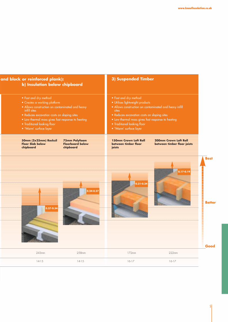
243mm 258mm 172mm 222mm
Good
Better
Best
• Fast and dry method• Utilises lightweight products• Allows construction on contaminated and heavy infill
sites• Reduces excavation costs on sloping sites• Low thermal mass gives fast response to heating• Traditional looking floor• ‘Warm’ surface layer
and block or reinforced plank):b) Insulation below chipboard
3) Suspended Timber
0.27-0.34
14-15 14-15 16-17 16-17
5
www.knaufinsulation.co.uk
50mm (2x25mm) RocksilFloor Slab belowchipboard
75mm PolyfoamFloorboard belowchipboard
150mm Crown Loft Rollbetween timber floorjoists
200mm Crown Loft Rollbetween timber floor joists
• Fast and dry method• Creates a working platform• Allows construction on contaminated and heavy
infill sites• Reduces excavation costs on sloping sites• Low thermal mass gives fast response to heating• Traditional looking floor• ‘Warm’ surface layer
0.24-0.27
0.21-0.24
0.17-0.19

6
www.knaufinsulation.co.uk
General
The three most important factors to consider
when insulating a ground floor are:
• What is the applied loading?
• Where is the insulation to be
positioned within the floor structure?
• What thickness of insulation will
be required to meet the Building
Regulations?
Other design considerations include
preventing condensation, minimising
air leakage and thermal bridging.
Applied Floor Loading
All materials are compressed under
load. Insulation materials used under
slabs, screeds and chipboard should be
capable of accommodating the applied
loads with the minimum of compression.
The applied load has two components:
• the dead load, which is due to the
weight of the materials laid on the
insulant, and
• the design load
BS 6399: Part 1: 1996 suggests that in
dwellings, a design load of 1.5 kN/m2
should be allowed for in all cases.
The dead loads applied by various
building components are shown in the
table. However, the designer must also
consider the dynamic loads and how
they are applied. BS 6399 is based on
the uniformly distributed load (UDL). The
strength of the floor must be sufficient to
support any applied loads over the
loaded area. For example, a large
cupboard raised on feet has a
significantly increased point loading
compared to one sat on the whole
base. The Applications section shows
the compression resistance of individual
insulants, where relevant.
Detailed Design Considerations
Suspended timber ground floors are
easily insulated
Dead loads applied by various building componentsElement Dead load (kN/m2)
Flooring grade chipboard 0.1 to 0.2
65mm concrete screed 1.50
75mm concrete screed 1.75
150mm concrete floor slab 3.50
Additional design load to BS 6399: Part 1: 1996 (dwellings) 1.50
www.knaufinsulation.co.uk
7
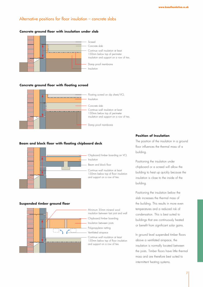
Position of Insulation
The position of the insulation in a ground
floor influences the thermal mass of a
building.
Positioning the insulation under
chipboard or a screed will allow the
building to heat up quickly because the
insulation is close to the inside of the
building.
Positioning the insulation below the
slab increases the thermal mass of
the building. This results in more even
temperatures and a reduced risk of
condensation. This is best suited to
buildings that are continuously heated
or benefit from significant solar gains.
In ground level suspended timber floors
above a ventilated airspace, the
insulation is normally located between
the joists. Timber floors have little thermal
mass and are therefore best suited to
intermittent heating systems.
Floating screed on slip sheet/VCL
Insulation
Concrete slab
Damp proof membrane
Concrete slab
Insulation
Damp proof membrane
Screed
Continue wall insulation at least150mm below top of perimeterinsulation and support on a row of ties.
Continue wall insulation at least150mm below top of perimeterinsulation and support on a row of ties.
Concrete ground floor with floating screed
Concrete ground floor with insulation under slab
Alternative positions for floor insulation – concrete slabs
Chipboard/timber boarding on VCL
Insulation
Beam and block floor
Insulation between joists
Chipboard/timber boarding
Polypropylene netting
Continue wall insulation at least150mm below top of floor insulationand support on a row of ties.
Ventilated airspace
Continue wall insulation at least150mm below top of floor insulationand support on a row of ties.
Beam and block floor with floating chipboard deck
Suspended timber ground floor
Minimum 35mm mineral woolinsulation between last joist and wall

8
www.knaufinsulation.co.uk
Building Regulation
Requirements
The table below shows the U-value
requirements in the Building Regulations
for ground floors.
U-value (W/m2K)
England, Wales and
Northern Ireland 0.25
Scotland 0.25 or 0.22
Ireland 0.25
In the various Building Regulations there
are trade off methods that allow the
performance of a particular building
element to be worse than the Elemental
U-value. This has to be compensated for
either by improving the performance in
other building elements, or the heating
system performance. There is usually a
maximum permissible U-value for each
element in the trade off methods.
Calculation of U-values
Unlike walls and roofs, the heat loss
through a ground floor varies with its
size and shape. The Building
Regulations require that when ground
floor U-values are calculated, BS EN
ISO 13370: 1998 should be used.
The British Standard uses the ratio of
the exposed floor perimeter to the floor
area to take account of the variation in
heat loss due to floor size and shape.
The measurement of the perimeter and
area should be to the finished inside
surfaces of the perimeter walls that
enclose the heated space. Projecting
bays should be included, but unheated
spaces such as porches or garages
should be excluded.
In the case of semi-detached and
terraced dwellings and blocks of flats,
the floor dimensions can either be taken
as those of the individual dwellings
themselves, or of the whole building.
When considering extensions to existing
buildings the floor dimensions may be
taken as those of the complete building
including the extension.
Determining the U-value
The charts above show the thickness of
insulation needed to achieve a U-value
of 0.25 W/m2K when insulating a
ground floor.
The charts are based on the ground
having a thermal conductivity of 1.5
W/mK. The U-values for Crown Loft Roll
assume it is placed between 50mm
wide timber floor joists spaced at
600mm centres. However, look up
tables, particularly for suspended ground
floors, only give a guide to the expected
performance. The high number of
Look up charts to achieve a U-value of 0.25 W/m2K
0.14 –0.19
0.12 –0.13
0.20 –0.229
0.30 –0.443
0.44 –1.00
up to 0.111
Polyfoam Floorboard Standardyfoam Floorboard Standard
P/Aratio
25 35 50 65 75
50
+
50
0.25 –0.339
0.19 –0.224
0.40 –0.883
0.84 –1.00
up to 0.188
Polyfoam Floorboard Standardm Floorboard Standard
P/Aratio
25 35 50 65 75
Concrete ground bearing slab Suspended concrete beam and block floor
Suspended timber floor
0.51 –1.00
0.20 –0.550
up to 0.199
Crown LoftRollCrown LoftRoll
P/A
ratio
100 150 170
www.knaufinsulation.co.uk
9
variables that have to be taken into
account can significantly affect the U-
value for a particular set of conditions.
To calculate U-values to your own
specific requirements, Knauf Insulation
recommend the use of its Architectural
Calculation Suite (ACS) version 5.09 –
alternatively, consult the Knauf Technical
Advisory Centre who can carry out the
calculations for you.
Condensation
A vapour barrier is not normally required
for most ground floor constructions.
However, a vapour barrier should be
installed between the insulation and a
chipboard floor, especially if there is a
risk of excessive moisture from the floor
slab drying out.
Thermal Bridging
Thermal bridges are a significant source
of heat loss. They may also cause
localised condensation and mould
growth.
Correct detailing at the junction of the
floor slab and external wall, as shown
in the details on page 7, will reduce
thermal bridging and thus the risk of
condensation.
Where insulation is placed between
timber joists, the joists have the potential
to act as thermal bridges. However,
where joists are at least 150mm deep
and the space between them is fully
filled with insulation, the timber does not
constitute a thermal bridge.
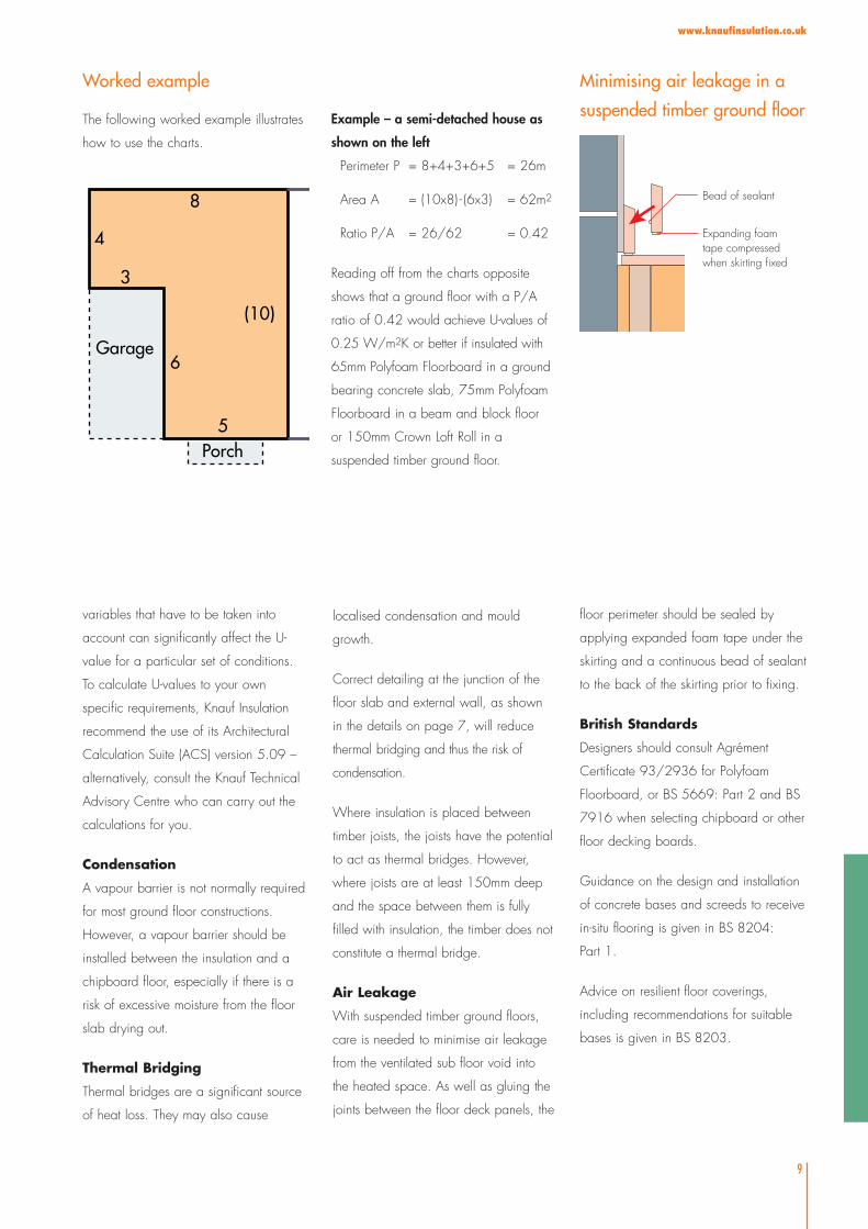
Air Leakage
With suspended timber ground floors,
care is needed to minimise air leakage
from the ventilated sub floor void into
the heated space. As well as gluing the
joints between the floor deck panels, the
floor perimeter should be sealed by
applying expanded foam tape under the
skirting and a continuous bead of sealant
to the back of the skirting prior to fixing.
British Standards
Designers should consult Agrément
Certificate 93/2936 for Polyfoam
Floorboard, or BS 5669: Part 2 and BS
7916 when selecting chipboard or other
floor decking boards.
Guidance on the design and installation
of concrete bases and screeds to receive
in-situ flooring is given in BS 8204:
Part 1.
Advice on resilient floor coverings,
including recommendations for suitable
bases is given in BS 8203.
3
4
8
(10)
5
6Garage
Porch
The following worked example illustrates
how to use the charts.
Worked example
Example – a semi-detached house as
shown on the left
Perimeter P = 8+4+3+6+5 = 26m
Area A = (10x8) - (6x3) = 62m2
Ratio P/A = 26/62 = 0.42
Reading off from the charts opposite
shows that a ground floor with a P/A
ratio of 0.42 would achieve U-values of
0.25 W/m2K or better if insulated with
65mm Polyfoam Floorboard in a ground
bearing concrete slab, 75mm Polyfoam
Floorboard in a beam and block floor
or 150mm Crown Loft Roll in a
suspended timber ground floor.
Bead of sealant
Expanding foamtape compressedwhen skirting fixed
Minimising air leakage in a
suspended timber ground floor
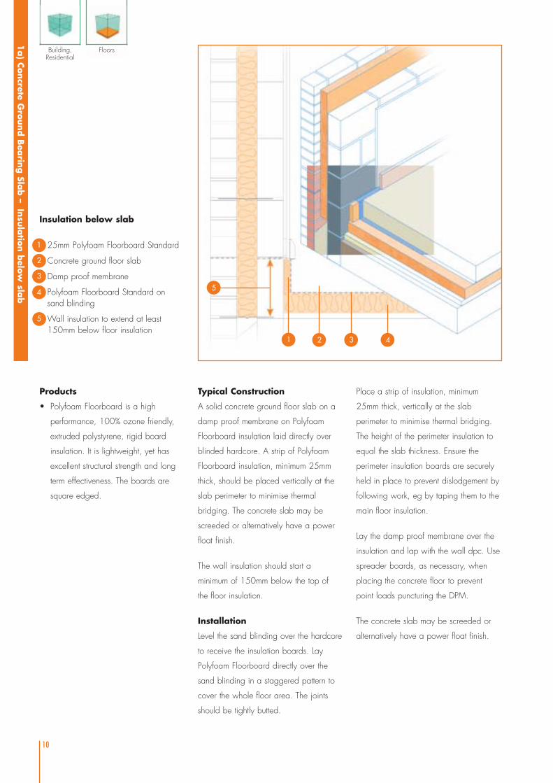
Insulation below slab
25mm Polyfoam Floorboard Standard
Concrete ground floor slab
Damp proof membrane
Polyfoam Floorboard Standard onsand blinding
Wall insulation to extend at least150mm below floor insulation
10
Typical Construction
A solid concrete ground floor slab on a
damp proof membrane on Polyfoam
Floorboard insulation laid directly over
blinded hardcore. A strip of Polyfoam
Floorboard insulation, minimum 25mm
thick, should be placed vertically at the
slab perimeter to minimise thermal
bridging. The concrete slab may be
screeded or alternatively have a power
float finish.
The wall insulation should start a
minimum of 150mm below the top of
the floor insulation.
Installation
Level the sand blinding over the hardcore
to receive the insulation boards. Lay
Polyfoam Floorboard directly over the
sand blinding in a staggered pattern to
cover the whole floor area. The joints
should be tightly butted.
Place a strip of insulation, minimum
25mm thick, vertically at the slab
perimeter to minimise thermal bridging.
The height of the perimeter insulation to
equal the slab thickness. Ensure the
perimeter insulation boards are securely
held in place to prevent dislodgement by
following work, eg by taping them to the
main floor insulation.
Lay the damp proof membrane over the
insulation and lap with the wall dpc. Use
spreader boards, as necessary, when
placing the concrete floor to prevent
point loads puncturing the DPM.
The concrete slab may be screeded or
alternatively have a power float finish.
1a) C
oncrete G
round B
earin
g Sla
b –
Insu
latio
n b
elow
slab
2
3
4
Products
• Polyfoam Floorboard is a high
performance, 100% ozone friendly,
extruded polystyrene, rigid board
insulation. It is lightweight, yet has
excellent structural strength and long
term effectiveness. The boards are
square edged.
Building,Residential
Floors
1
1
5
2 3
5
4
11
www.knaufinsulation.co.uk
Performance
• Thermal performance
Polyfoam Floorboard Standard is a high
performance insulant, with a thermal
conductivity of 0.029 W/mK. Unlike
most other insulants, the effect of
moisture on performance is negligible.
The table gives U-values for a range of
perimeter/area ratios. For an
explanation of how to calculate ground
floor U-values see page 9.
• Fire performance
When Polyfoam Floorboard is installed
in a concrete floor construction, it will
not contribute to the development stages
of a fire.
• Moisture resistance
The moisture resistance of Polyfoam
Floorboard allows it to be laid exposed
to ground water, with negligible impact
on performance. The board itself does
not perform the function of a damp
proof membrane. However, it can be
laid in damp conditions or up against
wet concrete without compromising its
thermal performance.
• Compression resistance
Polyfoam Floorboard is highly resistant
to compression. It is suitable for long
term static loads of up to 40 kPa, after
allowing a factor of safety of 5; and
occasional loading of up to 66 kPa,
after allowing a factor of safety of 3.
Certification
Polyfoam Floorboard Standard is third
party certified by the British Board of
Agrément.
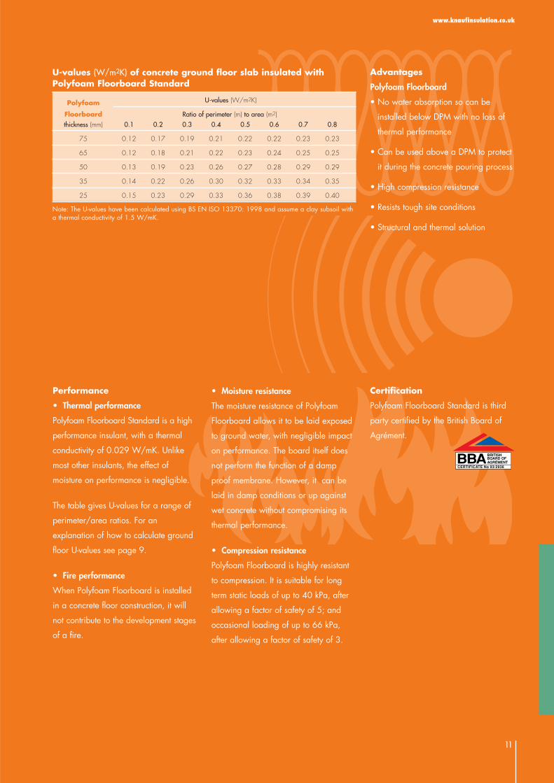
U-values (W/m2K) of concrete ground floor slab insulated withPolyfoam Floorboard Standard
Polyfoam U-values (W/m2K)
Floorboard Ratio of perimeter (m) to area (m2)thickness (mm) 0.1 0.2 0.3 0.4 0.5 0.6 0.7 0.8
75 0.12 0.17 0.19 0.21 0.22 0.22 0.23 0.23
65 0.12 0.18 0.21 0.22 0.23 0.24 0.25 0.25
50 0.13 0.19 0.23 0.26 0.27 0.28 0.29 0.29
35 0.14 0.22 0.26 0.30 0.32 0.33 0.34 0.35
25 0.15 0.23 0.29 0.33 0.36 0.38 0.39 0.40
Note: The U-values have been calculated using BS EN ISO 13370: 1998 and assume a clay subsoil witha thermal conductivity of 1.5 W/mK.
Advantages
Polyfoam Floorboard
• No water absorption so can be
installed below DPM with no loss of
thermal performance
• Can be used above a DPM to protect
it during the concrete pouring process
• High compression resistance
• Resists tough site conditions
• Structural and thermal solution

Insulation above slab
Flooring grade chipboard
Vapour control layer
Polyfoam Floorboard or Rocksil Floor Slab
Concrete floor slab
Damp proof membrane
Wall insulation to extend at least150mm below floor insulation
12
Typical Construction
A solid concrete ground floor slab on a
damp proof membrane on blinded
hardcore. Polyfoam Floorboard laid over
the whole of the concrete floor slab and
finished with either a screed or flooring
grade chipboard. Alternatively, Rocksil
Floor Slab can be used below flooring
grade chipboard.
Installation
Lay the Polyfoam Floorboard Standard
or Rocksil Floor Slab directly over the
whole of the concrete floor. The surface
of the floor should be smooth and flat
to within 5mm when measured with a
3m straight edge. Irregularities greater
than this must be levelled out. Where
a beam and block floor has a camber
or uneven upper surface a levelling screed
is recommended.
Chipboard finish
Where there is a risk of moisture from
drying out of the floor slab, a vapour
control layer, such as 1000 gauge
polythene, should be used. Lay the
vapour control layer over the insulation
and turn it up at the junction with the walls.
Lay the chipboard in a staggered pattern
and glue all joints using a waterproof
PVA adhesive. Leave an expansion gap
of at least 10mm or 2mm per metre
run of floor at the room perimeter. At
doorways or access traps to pipework
runs, support the cut edges of chipboard
on preservative treated battens.
Screed finish
Place a minimum 25mm thick vertical
piece of Polyfoam Floorboard to he
full depth of the screed, around the
perimeter minimise thermal bridging.
Tape the perimeter insulation boards
1b) C
oncrete G
round B
earin
g Sla
b –
Insu
latio
n a
bove sla
b
2
3
4
5
Products
• Polyfoam Floorboard is a high
performance, 100% ozone friendly,
extruded polystyrene, rigid board
insulation. It is lightweight, yet has
excellent structural strength and long
term effectiveness. The boards are
square edged.
• Rocksil Floor Slab is a rigid,
compression resistant slab of
non-combustible rock mineral wool.
Building,Residential
Floors
1
1
6
2 3 4 56
13
www.knaufinsulation.co.uk
Performance
• Thermal performance
Polyfoam Floorboard Standard is a high
performance insulant, with an aged
thermal conductivity of 0.029 W/mK.
Rocksil Floor Slab has a thermal
conductivity of 0.035 W/mK.
The table gives U-values for a range
of perimeter/area ratios. For an
explanation of how to calculate
ground floor U-values see page 8.
• Fire performance
When Polyfoam Floorboard is installed
in a floor construction it will not
contribute to the development stages
of a fire.
Rocksil Floor Slab is classified as
Euroclass A1 to BS EN ISO 13501-1.
• Compression resistance
Polyfoam Floorboard is highly resistant
to compression. It is suitable for long
term static loads of up to 40 kPa, after
allowing a factor of safety of 5; and
occasional loading of up to 66 kPa,
after allowing a factor of safety of 3.
Certification
Polyfoam Floorboard Standard is third
party certified by the British Board of
Agrément.
Advantages
Polyfoam Floorboard
• Compression resistant, supporting
screed under high point loads
• Provides high thermal performance
in limited insulation zone
• Structural and thermal solution
• Resistant to site damage
• Can be used as a working platform
for following trades before screed or
chipboard is laid
• Chipboard floors do not require battens
Rocksil Slab
• Will accommodate slight imperfections
in sub floor
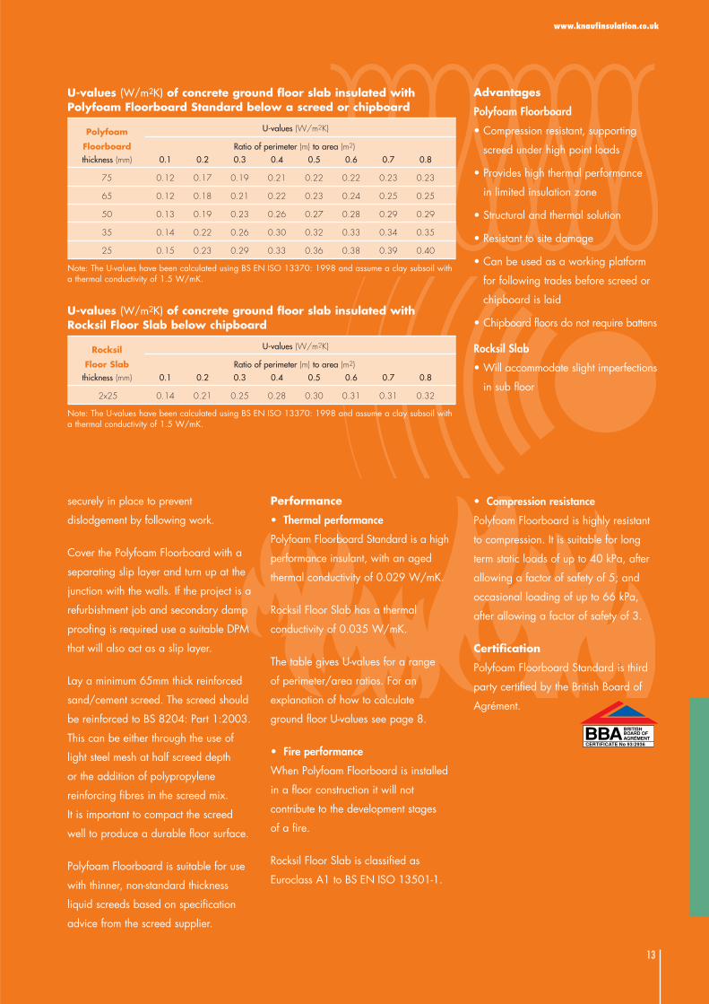
U-values (W/m2K) of concrete ground floor slab insulated withPolyfoam Floorboard Standard below a screed or chipboard
Polyfoam U-values (W/m2K)
Floorboard Ratio of perimeter (m) to area (m2)thickness (mm) 0.1 0.2 0.3 0.4 0.5 0.6 0.7 0.8
75 0.12 0.17 0.19 0.21 0.22 0.22 0.23 0.23
65 0.12 0.18 0.21 0.22 0.23 0.24 0.25 0.25
50 0.13 0.19 0.23 0.26 0.27 0.28 0.29 0.29
35 0.14 0.22 0.26 0.30 0.32 0.33 0.34 0.35
25 0.15 0.23 0.29 0.33 0.36 0.38 0.39 0.40
Note: The U-values have been calculated using BS EN ISO 13370: 1998 and assume a clay subsoil witha thermal conductivity of 1.5 W/mK.
U-values (W/m2K) of concrete ground floor slab insulated withRocksil Floor Slab below chipboard
Rocksil U-values (W/m2K)
Floor Slab Ratio of perimeter (m) to area (m2)thickness (mm) 0.1 0.2 0.3 0.4 0.5 0.6 0.7 0.8
2x25 0.14 0.21 0.25 0.28 0.30 0.31 0.31 0.32
Note: The U-values have been calculated using BS EN ISO 13370: 1998 and assume a clay subsoil witha thermal conductivity of 1.5 W/mK.
securely in place to prevent
dislodgement by following work.
Cover the Polyfoam Floorboard with a
separating slip layer and turn up at the
junction with the walls. If the project is a
refurbishment job and secondary damp
proofing is required use a suitable DPM
that will also act as a slip layer.
Lay a minimum 65mm thick reinforced
sand/cement screed. The screed should
be reinforced to BS 8204: Part 1:2003.
This can be either through the use of
light steel mesh at half screed depth
or the addition of polypropylene
reinforcing fibres in the screed mix.
It is important to compact the screed
well to produce a durable floor surface.
Polyfoam Floorboard is suitable for use
with thinner, non-standard thickness
liquid screeds based on specification
advice from the screed supplier.

Suspended concrete floor
Screed or chipboard
Isolating membrane
Polyfoam Floorboard or Rocksil Floor Slab
Suspended concrete floor
Ventilated sub floor
25mm Polyfoam Floorboard Standard
Wall insulation to extend at least150mm below floor insulation
14
Typical Construction
A concrete beam and block floor
overlaid with Polyfoam Floorboard and
finished with either flooring grade
chipboard or a sand/cement screed.
Polyfoam Floorboard is also suitable for
use with thinner, non-standard thickness
liquid screeds based on specification
advice from the screed supplier.
Where a screed is used, a strip of
Polyfoam Floorboard insulation, minimum
25mm thick, should be placed vertically
at the perimeter of the screed to minimise
thermal bridging. A slip layer of 1000
gauge polythene sheet should be placed
between the insulation and the screed.
The wall insulation should start a minimum
of 150mm below the top of the floor
perimeter insulation.
Installation
Polyfoam Floorboards can be used on a
beam and block suspended concrete
floor that is the subject of a current BBA
Certificate and installed in accordance
with, and within the limitations imposed
by that Certificate. The surface of any
floor should be smooth and flat to within
5mm when measured with a 3m straight
edge. Provided the surface is smooth
and level, the insulation may be laid
directly onto the flooring system.
Otherwise lay a thin levelling screed (this
may be the grout with beam and block
systems) prior to laying the insulation.
Irregularities greater than those detailed
above must be removed.
Where a beam and block floor has a
camber or uneven upper surface a
levelling screed is recommended.
2)
Susp
ended
Concrete Flo
or
2
3
4
5
Products
• Polyfoam Floorboard is a high
performance, 100% ozone friendly,
extruded polystyrene, rigid board
insulation. It is lightweight, yet has
excellent structural strength and long
term effectiveness. The boards are
square edged.
• Rocksil Floor Slab is a rigid,
compression resistant slab of
non-combustible rock mineral wool.
Building,Residential
Floors
1
5
7
6
16
7
2 3 4

15
www.knaufinsulation.co.uk
Screeded finish
Place a minimum 25mm thick vertical
piece of Polyfoam Floorboard, to the
full depth of the screed, around the
perimeter to minimise thermal bridging.
Ensure these perimeter insulation boards
are securely held in place to prevent
dislodgement by following work.
Lay the slip layer over the insulation and
turn up at the junction with the walls.
Lay a minimum 65mm thick reinforced
sand/cement screed. The screed should
be reinforced to BS 8204: Part 1 :
2003. This can be either through the
use of light steel mesh at half screed
depth or the addition of polypropylene
reinforcing fibres to the screed mix.
It is important to compact the screed
well to produce a durable floor surface.
Chipboard finish
The insulation should be laid over the
whole of the beam and block floor.
Lay the chipboard in a staggered pattern
with all joints glued using a waterproof
PVA adhesive. Leave an expansion gap
of at least 10mm or 2mm per metre
run of floor at the room perimeter. At
doorways or access traps to pipework
runs support the cut edges of chipboard
on preservative treated battens. If in
doubt refer to the board manufacturer’s
instructions.
Performance
• Thermal performance
Polyfoam Floorboard Standard is a high
performance insulant, with a thermal
conductivity of 0.029 W/mK.
Rocksil Floor Slab has a thermal
conductivity of 0.035 W/mK.
The table gives U-values for a range
of perimeter/area ratios. For an
explanation of how to calculate ground
floor U-values see page 8.
• Fire performance
When Polyfoam Floorboard is installed
in a floor construction it will not contribute
to the development stages of a fire.
Rocksil Floor Slab is classified as
Euroclass A1 to BS EN ISO 13501-1.
• Compression resistance
Polyfoam Floorboard is highly resistant
to compression. It is suitable for long
term static loads of up to 40 kPa, after
allowing a factor of safety of 5; and
occasional loading of up to 66 kPa,
after allowing a factor of safety of 3.
Certification
Polyfoam Floorboard Standard is third
party certified by the British Board of
Agrément.
U-values (W/m2K) of beam and block ground floor insulated withPolyfoam Floorboard Standard
Polyfoam U-values (W/m2K)
Floorboard Ratio of perimeter (m) to area (m2)thickness (mm) 0.1 0.2 0.3 0.4 0.5 0.6 0.7 0.8
25+65 0.15 0.19 0.21 0.22 0.23 0.24 0.24 0.24
75 0.17 0.21 0.24 0.25 0.26 0.27 0.28 0.28
65 0.18 0.23 0.25 0.27 0.29 0.30 0.30 0.31
50 0.19 0.26 0.30 0.32 0.34 0.35 0.36 0.37
35 0.22 0.30 0.35 0.38 0.41 0.43 0.44 0.46
25 0.23 0.33 0.40 0.44 0.48 0.50 0.52 0.54
Note: The U-values have been calculated using BS EN ISO 13370: 1998 and assume a dense infill blockbetween concrete beams.
Advantages
Polyfoam Floorboard
• Compression resistant, supporting
screed under high point loads
• Provides high thermal performance
in limited insulation zone
• Structural and thermal solution
• Resistant to site damage
• Can be used as a working platform
for following trades before screed or
chipboard is laid
• Chipboard floors do not require battens
Rocksil Slab
• Will accommodate slight imperfections
in sub floor
U-values (W/m2K) of beam and block ground floor insulated withRocksil Floor Slab below chipboard
Rocksil U-values (W/m2K)
Floor Slab Ratio of perimeter (m) to area (m2)thickness (mm) 0.1 0.2 0.3 0.4 0.5 0.6 0.7 0.8
2x25 0.17 0.22 0.27 0.30 0.32 0.34 0.35 0.36
Note: The U-values have been calculated using BS EN ISO 13370: 1998 and assume a dense infill blockbetween concrete beams.

Suspended timber floor
Draughtstrip
Crown Loft Roll
Floor deck
Crown Loft Roll
Support netting
Ventilated sub-floor
Wall insulation to extend at least150mm below floor insulation
16
Typical Construction
A suspended and ventilated timber
ground floor. The insulation is laid
between the joists and supported on
polypropylene netting.
The netting should be positioned to
support the insulation so that there is no
gap between the insulation and the
underside of the floor deck.
The floor joists running parallel with
masonry walls should be spaced at least
35mm away from the wall to allow
insulation to be placed next to the wall.
To minimise air leakage at the floor
perimeter, the skirting board should have
a self-adhesive strip of expanding foam
applied to its lower edge and a
continuous bead of sealant applied
to its back surface before fixing.
The wall insulation should start a minimum
of 150mm below the top of the floor
insulation.
Installation
If the insulation is the full depth of the
floor joists, staple the support netting to
the underside of the first joist and unroll
the netting, stapling to the underside of
each joist as the netting is unrolled.
Where the joist is deeper than the floor
insulation, mark the depth of the
insulation on the side of the joists. Staple
the support netting along this line and
pull taut to the adjacent joist and staple
again. Pull the netting over the top of the
joist and staple to the depth of the floor
insulation. Repeat the process until there
is netting support to the whole floor.
Unroll the Crown Loft Roll to completely
fill the space between the joists. There
3) Su
spen
ded
Timber Flo
or
2
3
4
5
Product
• Crown Loft Roll is made from glass
mineral wool and formed into
unfaced rolls which are lightweight,
flexible, resilient and non-combustible
Building,Residential
Floors
1
1
4 53 6
7
2
6
7

17
www.knaufinsulation.co.uk
Performance
• Thermal performance
Crown Loft Roll has a thermal
conductivity of 0.044 W/mK.
The table gives U-values for a range of
perimeter/area ratios. For an
explanation of how to calculate ground
floor U-values, see page 8.
• Fire performance
Crown Loft Roll is classified as Euroclass
A1 to BS EN ISO 13501-1.
U-values (W/m2K) of suspended timber ground floor insulated with Crown Loft Roll
Crown Loft Roll U-values (W/m2K)
thickness Ratio of perimeter (m) to area (m2)(mm) 0.1 0.2 0.3 0.4 0.5 0.6 0.7 0.8
200 0.13 0.16 0.17 0.18 0.19 0.19 0.19 0.20
170 0.14 0.18 0.19 0.20 0.21 0.22 0.22 0.22
150 0.15 0.19 0.21 0.22 0.23 0.24 0.24 0.24
100 0.18 0.23 0.26 0.28 0.30 0.31 0.32 0.32
Notes: The U-values have been calculated using BS EN ISO 13370: 1998 and assume 48mm widejoists at 600mm centres.
should be no air gap between the
insulation and the underside of the floor
deck. Joists running parallel with
masonry walls should be spaced away
from the wall to allow no less than
35mm of insulation to be placed next to
the wall.
Lay the chipboard floor deck in the
usual way, using waterproof PVA glue at
the joints, and allow a minimum 10mm
gap at the room perimeter.
When fixing the skirting board, apply a
self-adhesive foam strip to the underside
of the skirting and two beads of sealant
to the back surface. Apply pressure to
ensure the foam strip is compressed
immediately before fixing the skirting
in place.
Advantages
• Crown Loft Roll is manufactured to suit
standard joist spacings, so no cutting
is required
• Insulation friction fitted between joists,
with tight fit against timber
• Non-combustible product
• Low embodied energy and
environmentally friendly
www.knaufinsulation.co.uk
18
1) Ground bearing slab
1a) Insulation under slab
The whole of the ground floor area
between brick, block or concrete
subwalls to be insulated with Polyfoam
Floorboard Standard …...mm thick and
laid directly over blinded hardcore.
Polyfoam Floorboard, at least 25mm
thick, to be cut and placed vertically
against the subwalls to the depth of the
concrete slab.
The insulation to be laid above*/below*
damp proof membrane, which should
lap the perimeter wall dpc. Concrete
slab and floor finish as specified by
the designer. (*delete as required)
Alternatively, refer to NBS clause:
E20/30 or E20/200
1b) Insulation above slab and
below screed
Polyfoam Floorboard Standard ......mm
thick, to be closely butted and placed
over the whole area of the floor.
Polyfoam Floorboard, at least 25mm
thick, to be cut and placed to full depth
of screed at the floor perimeter.
The insulation to be overlaid with 1200
gauge polythene, taken up and over the
perimeter insulation. A 65mm thick
sand/cement screed with wire mesh*/
polypropylene reinforcing fibres* to be
laid on top. (NHBC recommend a D49
fabric mesh for use in floating screeds.)
Floor finish as specified by the designer.
(* delete as appropriate)
Typical Specification ClausesAlternatively, refer to NBS clause:
M10/40 or M10/290
1b) Insulation above slab and
below chipboard
The whole area of the concrete floor to
be lined with Polyfoam Floorboard
Standard, …...mm thick. All boards to
be close butted.
The insulation to be (overlaid with a
vapour control layer of 1000g
polythene and)* covered with 18mm
t&g flooring grade chipboard. (*delete
as required)
Alternatively, refer to NBS clause:
K11/25 or K11/225
2) Suspended masonry floor
2a) Insulation below screed
Polyfoam Floorboard Standard ......mm
thick, to be closely butted and placed
over the whole area of the floor.
Polyfoam Floorboard, at least 25mm
thick, to be cut and placed to full depth
of screed at the floor perimeter.
The insulation to be overlaid with 1200
gauge polythene, taken up and over the
perimeter insulation. A 65mm thick
sand/cement screed with wire mesh*/
polypropylene reinforcing fibres* to be
laid on top. (NHBC recommend a D49
fabric mesh for use in floating screeds.)
Floor finish as specified by the designer.
(* delete as appropriate)
Alternatively, refer to NBS clause:
M10/40 or M10/290
2b) Insulation below chipboard
The whole area of the concrete floor to
be lined with Polyfoam Floorboard
Standard, …...mm thick. All boards to
be close butted.
The insulation to be (overlaid with a
vapour control layer of 1000g polythene
and)* covered with 18mm t&g flooring
grade chipboard. (*delete as required)
Alternatively, refer to NBS clause:
K11/25 or K11/225
3) Timber suspended floor
Polypropylene netting to be (draped over
and between the joists and stapled to
the sides of each joist*/stapled to the
underside of the joists*). (*delete as
required)
Crown Loft Roll of ......mm thickness and
of width to suit joist spacings, supported
on the netting to fit tightly under the floor.
Crown Loft Roll to be cut and placed to
fully fill in the gap between the last joist
and the perimeter wall. T&g flooring
grade chipboard to be nailed or
screwed to the floor joists, all as
specified by the designer.
Alternatively, refer to NBS clause:
P10/240 or P10/250

www.knaufinsulation.co.uk
19
Residential
Pitched Roofs External Walls Internal Walls Floors
Upper Floors(N&C)Solutions for insulatingexposed aboveground floors inboth timber andconcreteconstruction
Ground Floor(N)Solutions forinsulating bothslab on andsuspendedground floors in both concreteand timberconstruction
Basement Walls
Masonry Solid(N&C)Solutions forexternal basementwall to preventthermal transitionto the earth
Partition Walls(N&C)Solutions fordividing internalrooms in singledwellingconstruction
SeparatingWalls (N&C)Solutions for highperformanceseparating wallsbetween separate,but attacheddwellings
New Build andUpgrade (N)Solutions for new build "room in roof",warm roof andceiling level coldroof insulation andupgrading existingcold roof insulation
Loft Conversion -Room in Roof (C)Solutions forconverting existingattic space into living area
Masonry Cavity(N&C)Solutions formasonry cavity wallconstructionfull and part fill
Timber Frame (N)Solutions forinsulation inmodern timberframe homes
Masonry Solid (N&C)Solutions forinternal andexternal insulationapplied to solidmasonry walls
B/R/PR/1 B/R/XW/1 B/R/IW/1 B/R/BW/1 B/R/F/1
B/R/F/2
Separating andInternal Floors(N&C)Acousticsolutions forfloors separatingtwo dwellingsand floors withina single dwelling
B/R/F/3
B/R/IW/2
B/R/PR/2
B/R/XW/2
B/R/XW/3
Detached Homes Semi Detached Homes Terraced Homes Apartments
Building & Construction
N= New Build C= Conversion
Legend
B/NR/CS/1
Each green “box” referencemeans that a dedicatedbrochure is available on this application

Mar 2004This information booklet is complemented
by comprehensive specification and
application system recommendations
in the Knauf Insulation Guide, available
through visiting our website.
Customer Service (Sales)
Freephone 0800 627465
Fax: 01744 612007
E-mail: [email protected]
Insulation Academy Technical
Advisory Centre
Tel: 01744 693885
Fax: 01744 693882
E-mail: [email protected]
Literature
Tel: 01270 824024
Fax: 01270 824025
E-mail: [email protected]
Website
www.knaufinsulation.co.uk (UK)
www.knaufinsulation.ie (Ireland)
Knauf Insulation Ltd
PO Box 10
Stafford Rd
St Helens
Merseyside
WA10 3NS
B/R/F/1