ground improvement equipment · two main vibrolance techniques: vibro compaction and stone columns....
TRANSCRIPT
GROUND IMPROVEMENT EQUIPMENT For stone columns and vibro compaction
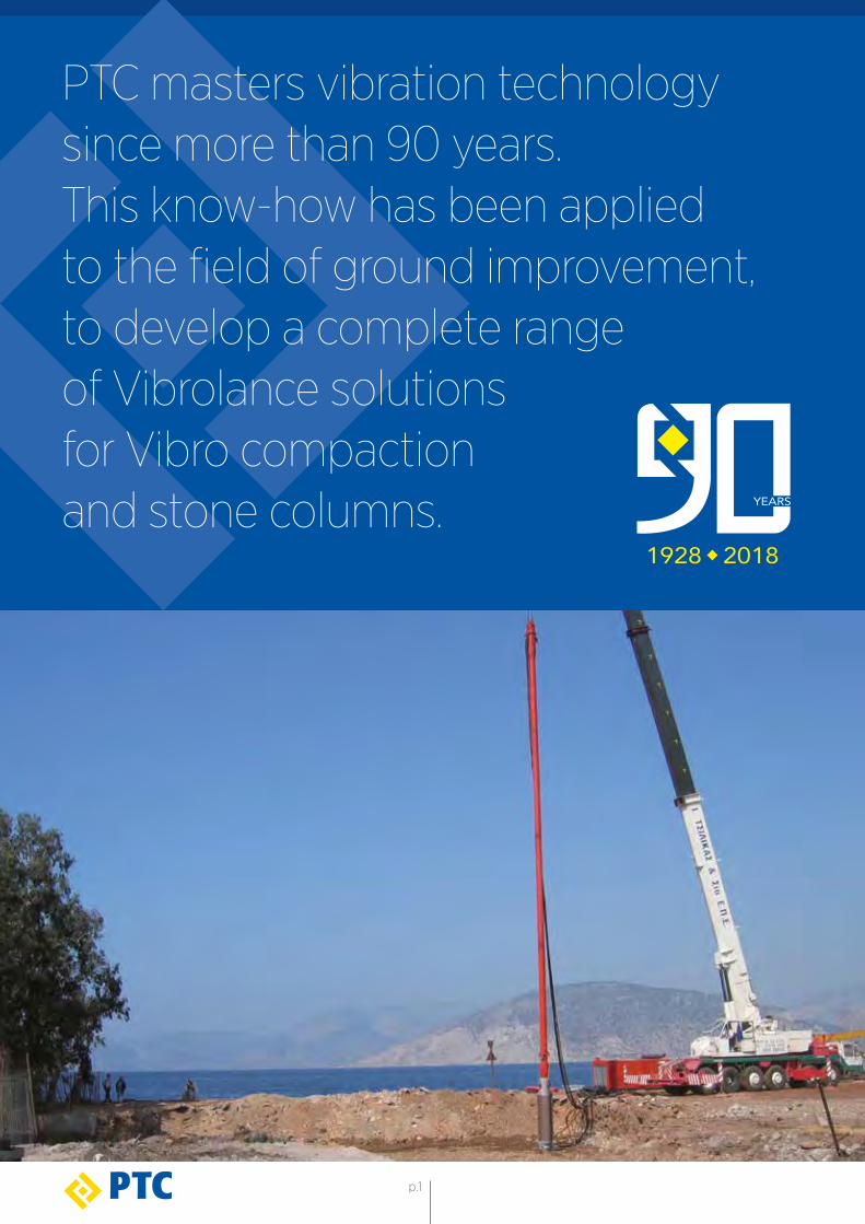
PTC masters vibration technologysince more than 90 years. This know-how has been appliedto the field of ground improvement, to develop a complete rangeof Vibrolance solutions for Vibro compactionand stone columns.
p.1
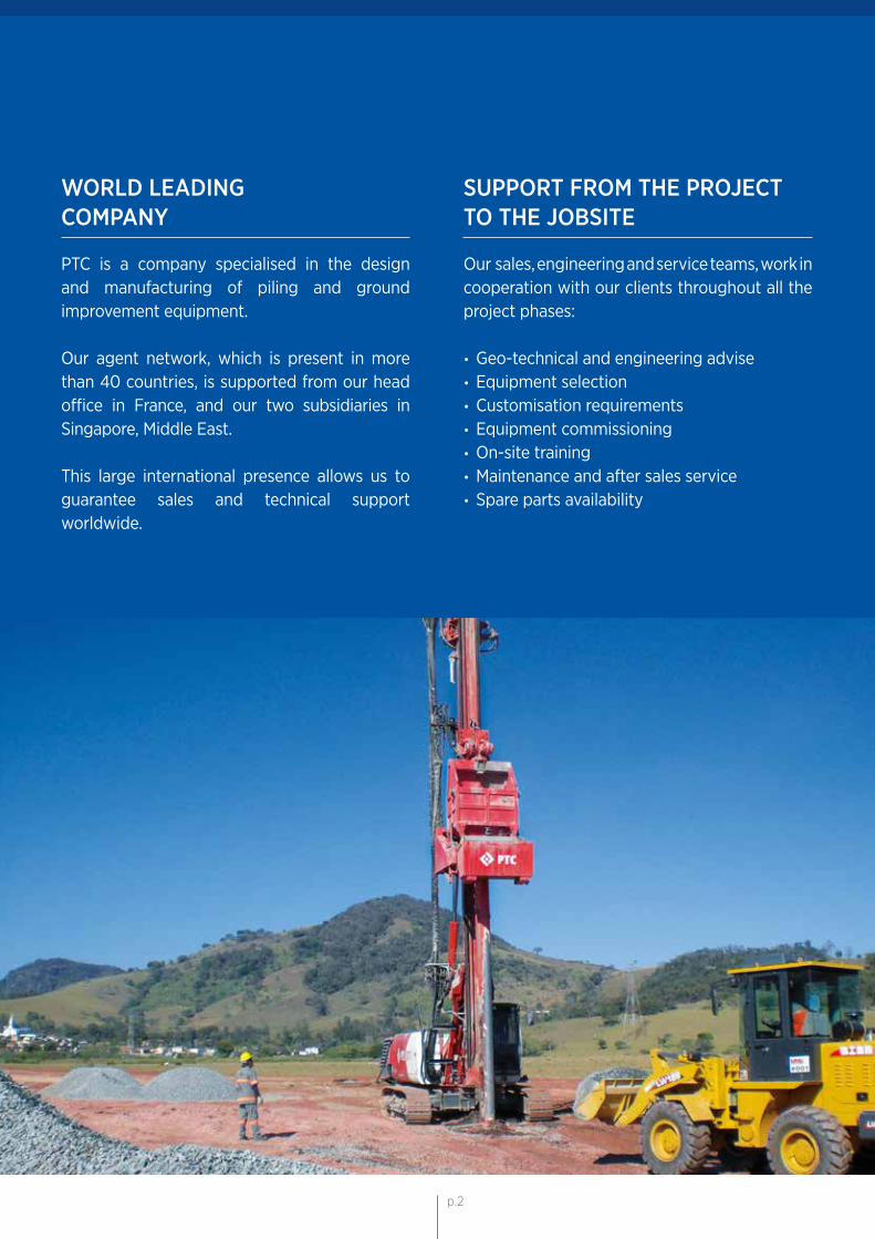
SUPPORT FROM THE PROJECT TO THE JOBSITE Our sales, engineering and service teams, work in cooperation with our clients throughout all the project phases: • Geo-technical and engineering advise • Equipment selection • Customisation requirements • Equipment commissioning • On-site training • Maintenance and after sales service • Spare parts availability
WORLD LEADING COMPANY
PTC is a company specialised in the design and manufacturing of piling and ground improvement equipment.
Our agent network, which is present in more than 40 countries, is supported from our head office in France, and our two subsidiaries in Singapore, Middle East.
This large international presence allows us to guarantee sales and technical support worldwide.
p.2
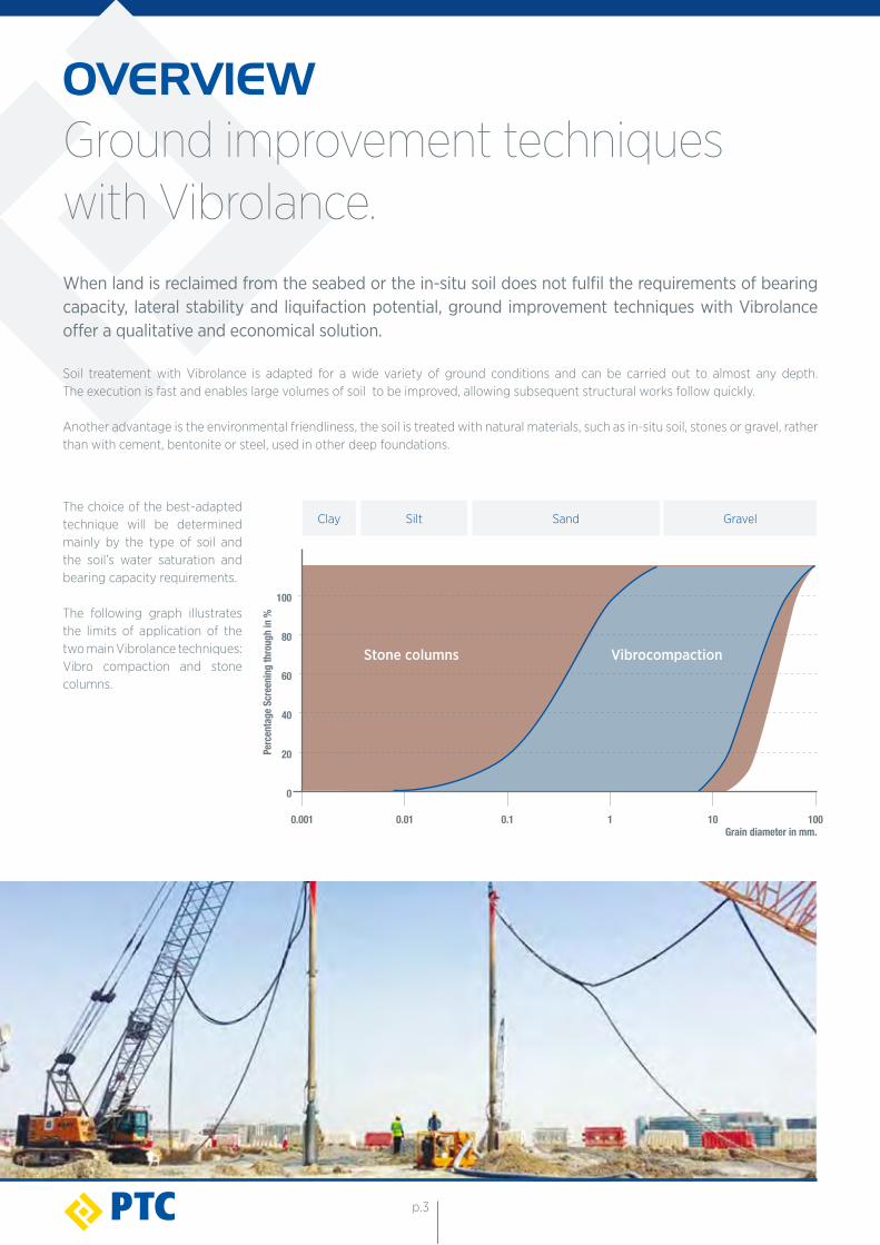
100
80
60
20
40
0
Grain diameter in mm.0.01 0.1 1 10 1000.001
Silt Sand Gravel
Perc
enta
ge S
cree
ning t
hrou
gh in
%
Clay
Stone columns Vibrocompaction
The choice of the best-adapted technique will be determined mainly by the type of soil and the soil’s water saturation and bearing capacity requirements.
The following graph illustrates the limits of application of the two main Vibrolance techniques: Vibro compaction and stone columns.
When land is reclaimed from the seabed or the in-situ soil does not fulfil the requirements of bearing capacity, lateral stability and liquifaction potential, ground improvement techniques with Vibrolance offer a qualitative and economical solution.
Soil treatement with Vibrolance is adapted for a wide variety of ground conditions and can be carried out to almost any depth. The execution is fast and enables large volumes of soil to be improved, allowing subsequent structural works follow quickly. Another advantage is the environmental friendliness, the soil is treated with natural materials, such as in-situ soil, stones or gravel, rather than with cement, bentonite or steel, used in other deep foundations.
OVERVIEWGround improvement techniqueswith Vibrolance.
p.3
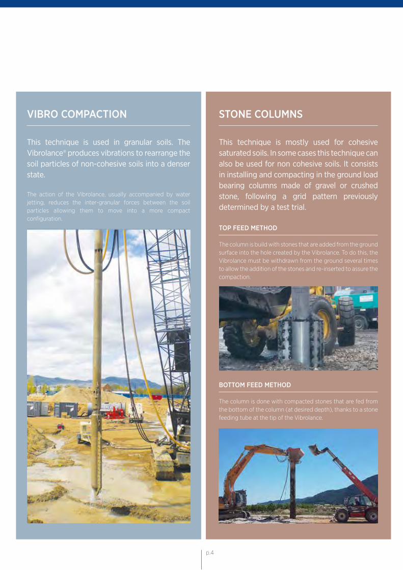
VIBRO COMPACTION
This technique is used in granular soils. The Vibrolance® produces vibrations to rearrange the soil particles of non-cohesive soils into a denser state.
The action of the Vibrolance, usually accompanied by water jetting, reduces the inter-granular forces between the soil particles allowing them to move into a more compact configuration.
BOTTOM FEED METHOD
The column is done with compacted stones that are fed from the bottom of the column (at desired depth), thanks to a stone feeding tube at the tip of the Vibrolance.
STONE COLUMNS
This technique is mostly used for cohesive saturated soils. In some cases this technique can also be used for non cohesive soils. It consists in installing and compacting in the ground load bearing columns made of gravel or crushed stone, following a grid pattern previously determined by a test trial.
TOP FEED METHOD
The column is build with stones that are added from the ground surface into the hole created by the Vibrolance. To do this, the Vibrolance must be withdrawn from the ground several times to allow the addition of the stones and re-inserted to assure the compaction.
p.4
THE VIBROLANCE®
DESCRIPTION & FEATURES
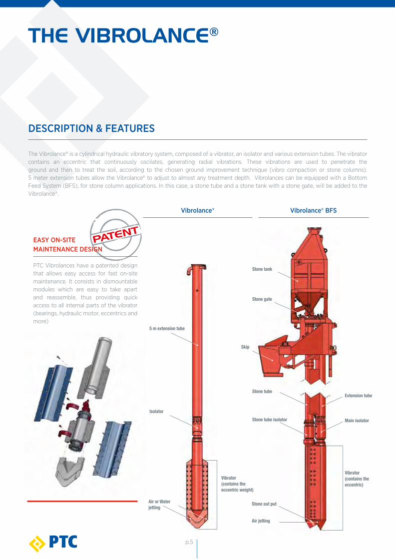
The Vibrolance® is a cylindrical hydraulic vibratory system, composed of a vibrator, an isolator and various extension tubes. The vibrator contains an eccentric that continuously oscilates, generating radial vibrations. These vibrations are used to penetrate the ground and then to treat the soil, according to the chosen ground improvement technique (vibro compaction or stone columns). 5 meter extension tubes allow the Vibrolance® to adjust to almost any treatment depth. Vibrolances can be equipped with a Bottom Feed System (BFS), for stone column applications. In this case, a stone tube and a stone tank with a stone gate, will be added to the Vibrolance®.
EASY ON-SITE MAINTENANCE DESIGN
PTC Vibrolances have a patented design that allows easy access for fast on-site maintenance. It consists in dismountable modules which are easy to take apart and reassemble, thus providing quick access to all internal parts of the vibrator (bearings, hydraulic motor, eccentrics and more)
Isolator
5 m extension tube
Stone tank
Stone tube
Stone gate
Stone tube isolator Main isolator
Extension tube
Vibrator(contains theeccentric weight)
Vibrator(contains theeccentric)
Skip
Vibrolance® Vibrolance® BFS
Stone out putAir or Water jetting
Air jetting
p.5
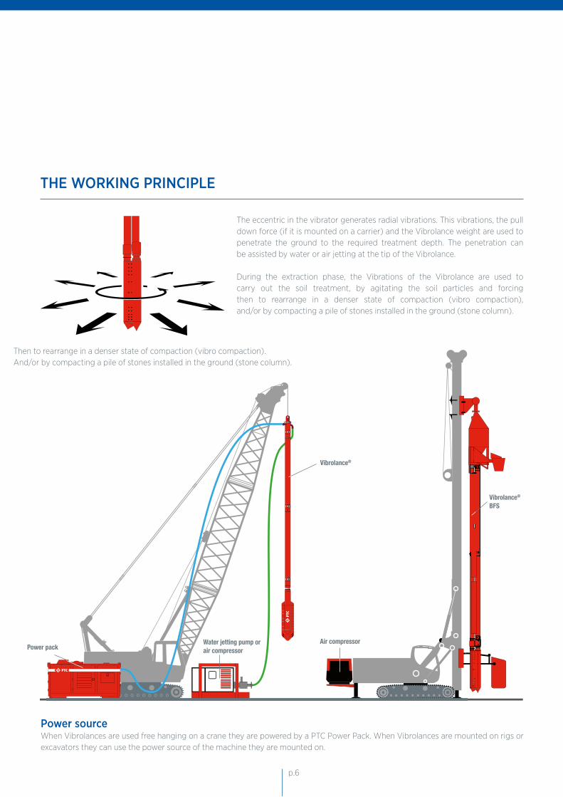
Vibrolance®
Power packWater jetting pump orair compressor
Vibrolance® BFS
Air compressor
The eccentric in the vibrator generates radial vibrations. This vibrations, the pull down force (if it is mounted on a carrier) and the Vibrolance weight are used to penetrate the ground to the required treatment depth. The penetration can be assisted by water or air jetting at the tip of the Vibrolance.
During the extraction phase, the Vibrations of the Vibrolance are used to carry out the soil treatment, by agitating the soil particles and forcing then to rearrange in a denser state of compaction (vibro compaction), and/or by compacting a pile of stones installed in the ground (stone column).
Then to rearrange in a denser state of compaction (vibro compaction).And/or by compacting a pile of stones installed in the ground (stone column).
Power sourceWhen Vibrolances are used free hanging on a crane they are powered by a PTC Power Pack. When Vibrolances are mounted on rigs or excavators they can use the power source of the machine they are mounted on.
THE WORKING PRINCIPLE
p.6
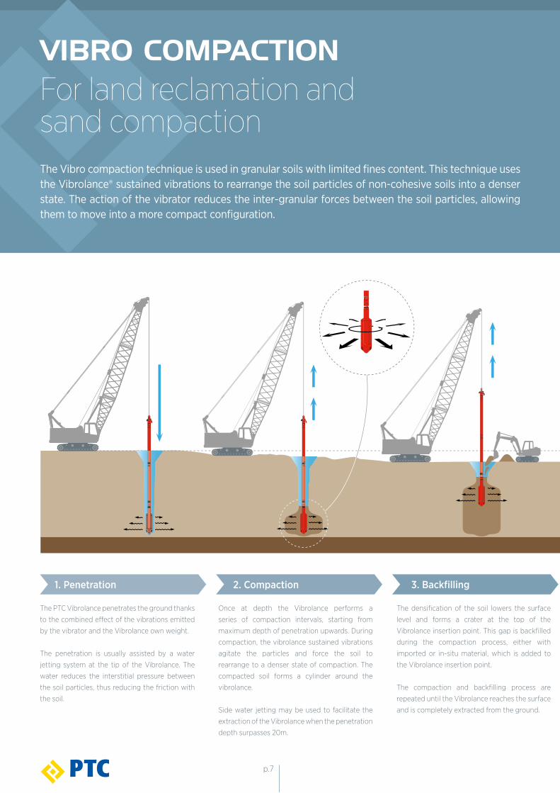
VIBRO COMPACTIONFor land reclamation andsand compactionThe Vibro compaction technique is used in granular soils with limited fines content. This technique uses the Vibrolance® sustained vibrations to rearrange the soil particles of non-cohesive soils into a denser state. The action of the vibrator reduces the inter-granular forces between the soil particles, allowing them to move into a more compact configuration.
1. Penetration 2. Compaction 3. Backfilling
The PTC Vibrolance penetrates the ground thanks
to the combined effect of the vibrations emitted
by the vibrator and the Vibrolance own weight.
The penetration is usually assisted by a water
jetting system at the tip of the Vibrolance. The
water reduces the interstitial pressure between
the soil particles, thus reducing the friction with
the soil.
Once at depth the Vibrolance performs a
series of compaction intervals, starting from
maximum depth of penetration upwards. During
compaction, the vibrolance sustained vibrations
agitate the particles and force the soil to
rearrange to a denser state of compaction. The
compacted soil forms a cylinder around the
vibrolance.
Side water jetting may be used to facilitate the
extraction of the Vibrolance when the penetration
depth surpasses 20m.
The densification of the soil lowers the surface
level and forms a crater at the top of the
Vibrolance insertion point. This gap is backfilled
during the compaction process, either with
imported or in-situ material, which is added to
the Vibrolance insertion point.
The compaction and backfilling process are
repeated until the Vibrolance reaches the surface
and is completely extracted from the ground.
p.7
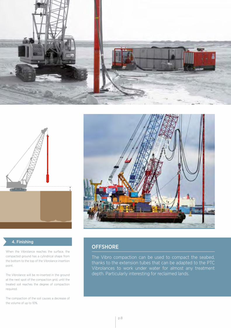
4. FinishingOFFSHORE
The Vibro compaction can be used to compact the seabed, thanks to the extension tubes that can be adapted to the PTC Vibrolances to work under water for almost any treatment depth. Particularly interesting for reclaimed lands.
When the Vibrolance reaches the surface, the
compacted ground has a cylindrical shape from
the bottom to the top of the Vibrolance insertion
point.
The Vibrolance will be re-inserted in the ground
at the next spot of the compaction grid, until the
treated soil reaches the degree of compaction
required.
The compaction of the soil causes a decrease of
the volume of up to 10%.
p.8p.8
VIBRO COMPACTION
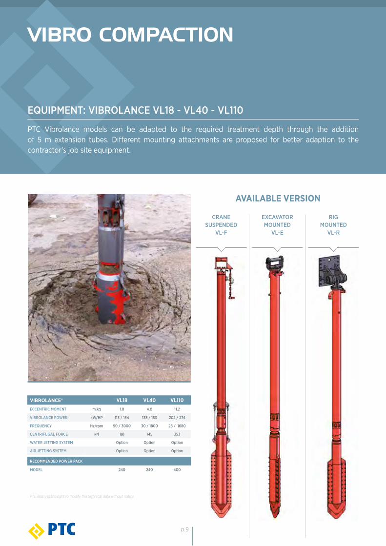
EQUIPMENT: VIBROLANCE VL18 - VL40 - VL110
PTC Vibrolance models can be adapted to the required treatment depth through the addition of 5 m extension tubes. Different mounting attachments are proposed for better adaption to the contractor’s job site equipment.
VIBROLANCE® VL18 VL40 VL110ECCENTRIC MOMENT m.kg 1.8 4.0 11.2
VIBROLANCE POWER kW/HP 113 / 154 135 / 183 202 / 274
FREQUENCY Hz/rpm 50 / 3000 30 / 1800 28 / 1680
CENTRIFUGAL FORCE kN 181 145 353
WATER JETTING SYSTEM Option Option Option
AIR JETTING SYSTEM Option Option Option
RECOMMENDED POWER PACK
MODEL 240 240 400
PTC reserves the right to modify the technical data without notice.
CRANE SUSPENDED
VL-F
EXCAVATOR MOUNTED
VL-E
RIG MOUNTED
VL-R
AVAILABLE VERSION
p.9
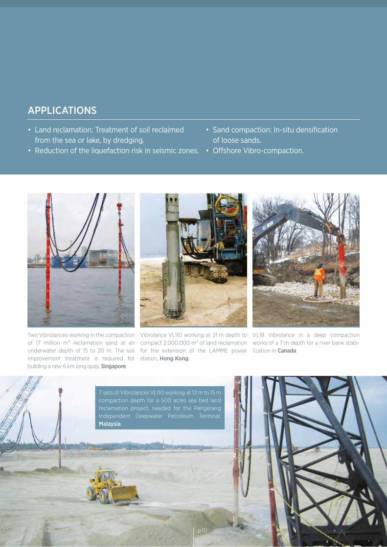
APPLICATIONS
• Land reclamation: Treatment of soil reclaimed from the sea or lake, by dredging.• Reduction of the liquefaction risk in seismic zones.
• Sand compaction: In-situ densification of loose sands.• Offshore Vibro-compaction.
Two Vibrolances working in the compaction of 17 million m³ reclamation sand at an underwater depth of 15 to 20 m. The soil improvement treatment is required for building a new 6 km long quay, Singapore.
Vibrolance VL110 working at 31 m depth to compact 2.000.000 m3 of land reclamation for the extension of the LAMME power station, Hong Kong.
VL18 Vibrolance in a deep compaction works of a 7 m depth for a river bank stabi-lization in Canada.
7 sets of Vibrolances VL110 working at 12 m to 15 m compaction depth for a 500 acres sea bed land reclamation project, needed for the Pengerang Independent Deepwater Petroleum Terminal, Malaysia.
p.10
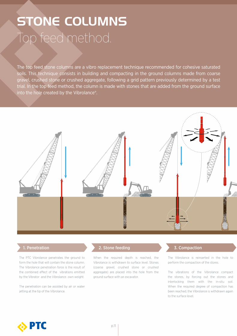
STONE COLUMNSTop feed method.
The top feed stone columns are a vibro replacement technique recommended for cohesive saturated soils. This technique consists in building and compacting in the ground columns made from coarse gravel, crushed stone or crushed aggregate, following a grid pattern previously determined by a test trial. In the top feed method, the column is made with stones that are added from the ground surface into the hole created by the Vibrolance®.
The PTC Vibrolance penetrates the ground to
form the hole that will contain the stone column.
The Vibrolance penetration force is the result of
the combined effect of the vibrations emitted
by the Vibrator and the Vibrolance own weight.
The penetration can be assisted by air or water
jetting at the tip of the Vibrolance.
When the required depth is reached, the
Vibrolance is withdrawn to surface level. Stones
(coarse gravel, crushed stone or crushed
aggregate) are placed into the hole from the
ground surface with an excavator.
The Vibrolance is reinserted in the hole to
perform the compaction of the stores.
The vibrations of the Vibrolance compact
the stones, by forcing out the stones and
interlocking them with the in-situ soil.
When the required degree of compaction has
been reached, the Vibrolance is withdrawn again
to the surface level.
1. Penetration 2. Stone feeding 3. Compaction
p.11
OFFSHORE
Top Feed stone columns can be installed under water. For this application the most commonly used method is to install a blanket of gravel on the seabed. Afterwards, the Vibrolance® penetrates the water, the gravel blanket and finally the seabed at desired depth. The gravel on the seabed is pushed down to the hole created by the Vibrolance, and forms a stone column.
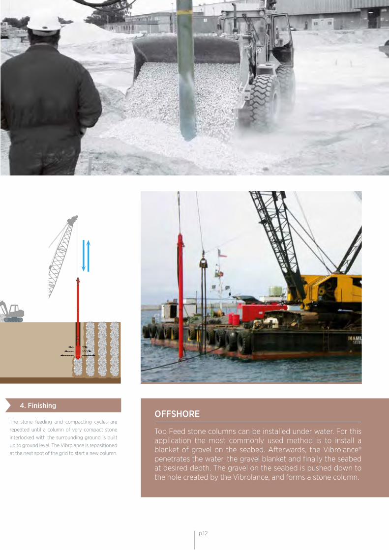
The stone feeding and compacting cycles are
repeated until a column of very compact stone
interlocked with the surrounding ground is built
up to ground level. The Vibrolance is repositioned
at the next spot of the grid to start a new column.
4. Finishing
p.12p.12
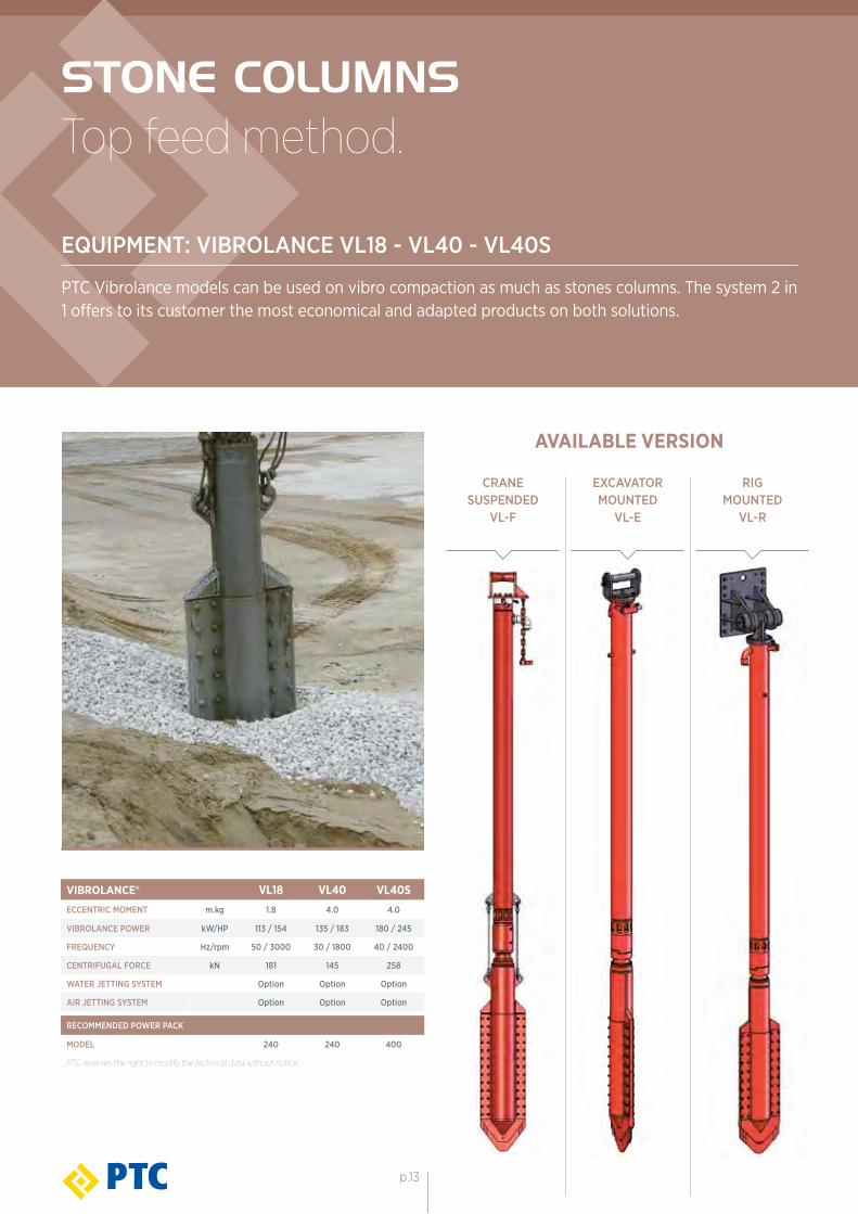
STONE COLUMNSTop feed method.
EQUIPMENT: VIBROLANCE VL18 - VL40 - VL40S
PTC Vibrolance models can be used on vibro compaction as much as stones columns. The system 2 in 1 offers to its customer the most economical and adapted products on both solutions.
VIBROLANCE® VL18 VL40 VL40SECCENTRIC MOMENT m.kg 1.8 4.0 4.0
VIBROLANCE POWER kW/HP 113 / 154 135 / 183 180 / 245
FREQUENCY Hz/rpm 50 / 3000 30 / 1800 40 / 2400
CENTRIFUGAL FORCE kN 181 145 258
WATER JETTING SYSTEM Option Option Option
AIR JETTING SYSTEM Option Option Option
RECOMMENDED POWER PACK
MODEL 240 240 400
PTC reserves the right to modify the technical data without notice.
CRANE SUSPENDED
VL-F
EXCAVATOR MOUNTED
VL-E
RIG MOUNTED
VL-R
AVAILABLE VERSION
p.13
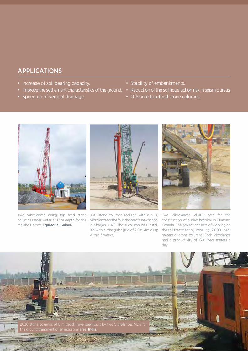
APPLICATIONS
2030 stone columns of 8 m depth have been built by two Vibrolances VL18 for the ground treatment of an industrial area, India.
Two Vibrolances doing top feed stone columns under water at 17 m depth for the Malabo Harbor, Equatorial Guinea.
900 stone columns realized with a VL18 Vibrolance for the foundation of a new school in Sharjah. UAE. Those column was instal-led with a triangular grid of 2.5m, 4m deep within 3 weeks.
Two Vibrolances VL40S sets for the construction of a new hospital in Quebec, Canada. The project consists of working on the soil treatment by installing 12 000 linear meters of stone columns. Each Vibrolance had a productivity of 150 linear meters a day.
• Increase of soil bearing capacity.• Improve the settlement characteristics of the ground.• Speed up of vertical drainage.
• Stability of embankments.• Reduction of the soil liquefaction risk in seismic areas.• Offshore top-feed stone columns.
p.14p.14
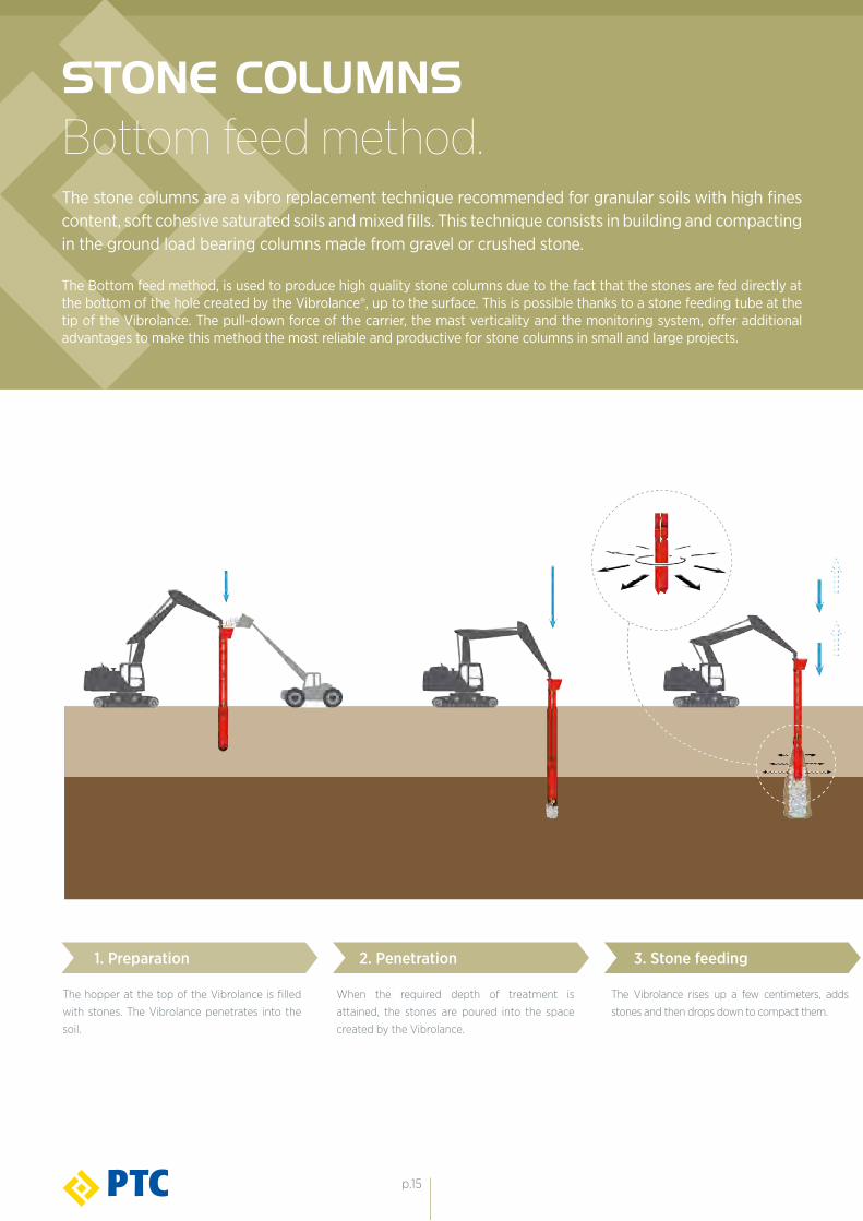
1. Preparation 2. Penetration 3. Stone feeding
The hopper at the top of the Vibrolance is filled
with stones. The Vibrolance penetrates into the
soil.
When the required depth of treatment is
attained, the stones are poured into the space
created by the Vibrolance.
The Vibrolance rises up a few centimeters, adds
stones and then drops down to compact them.
STONE COLUMNSBottom feed method.The stone columns are a vibro replacement technique recommended for granular soils with high fines content, soft cohesive saturated soils and mixed fills. This technique consists in building and compacting in the ground load bearing columns made from gravel or crushed stone.
The Bottom feed method, is used to produce high quality stone columns due to the fact that the stones are fed directly at the bottom of the hole created by the Vibrolance®, up to the surface. This is possible thanks to a stone feeding tube at the tip of the Vibrolance. The pull-down force of the carrier, the mast verticality and the monitoring system, offer additional advantages to make this method the most reliable and productive for stone columns in small and large projects.
p.15
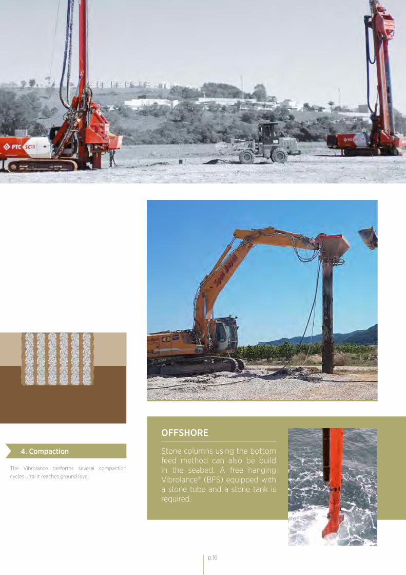
4. Compaction
OFFSHORE
Stone columns using the bottom feed method can also be build in the seabed. A free hanging Vibrolance® (BFS) equipped with a stone tube and a stone tank is required.
The Vibrolance performs several compaction
cycles until it reaches ground level.
p.16p.16
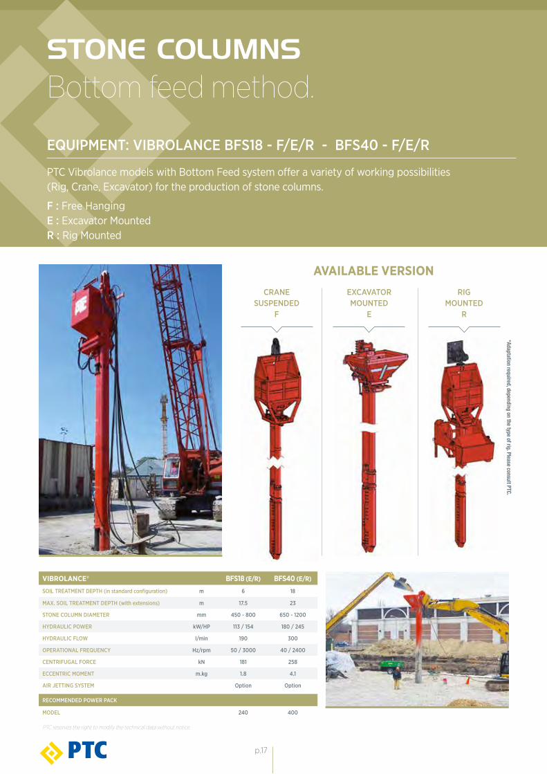
VIBROLANCE® BFS18 (E/R) BFS40 (E/R)
SOIL TREATMENT DEPTH (in standard configuration) m 6 18
MAX. SOIL TREATMENT DEPTH (with extensions) m 17.5 23
STONE COLUMN DIAMETER mm 450 - 800 650 - 1200
HYDRAULIC POWER kW/HP 113 / 154 180 / 245
HYDRAULIC FLOW l/min 190 300
OPERATIONAL FREQUENCY Hz/rpm 50 / 3000 40 / 2400
CENTRIFUGAL FORCE kN 181 258
ECCENTRIC MOMENT m.kg 1.8 4.1
AIR JETTING SYSTEM Option Option
RECOMMENDED POWER PACK
MODEL 240 400
PTC reserves the right to modify the technical data without notice.
*Adaptation required, depending on the type of rig. Please consult PTC.
STONE COLUMNSBottom feed method.
EQUIPMENT: VIBROLANCE BFS18 - F/E/R - BFS40 - F/E/R
PTC Vibrolance models with Bottom Feed system offer a variety of working possibilities (Rig, Crane, Excavator) for the production of stone columns.
RIG MOUNTED
R
EXCAVATOR MOUNTED
E
CRANE SUSPENDED
F
F : Free Hanging E : Excavator MountedR : Rig Mounted
AVAILABLE VERSION
p.17
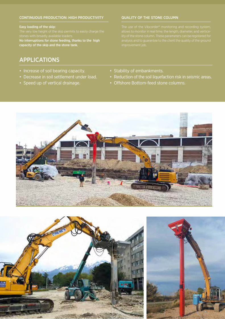
APPLICATIONS
• Increase of soil bearing capacity.• Decrease in soil settlement under load. • Speed up of vertical drainage.
• Stability of embankments.• Reduction of the soil liquefaction risk in seismic areas.• Offshore Bottom-feed stone columns.
CONTINUOUS PRODUCTION: HIGH PRODUCTIVITY
Easy loading of the skip: The very low height of the skip permits to easily charge the stones with broadly available loaders.No interruptions for stone feeding, thanks to the high capacity of the skip and the stone tank.
QUALITY OF THE STONE COLUMN
The use of the Vibcorder® monitoring and recording system, allows to monitor in real time: the length, diameter, and vertica-lity of the stone column. These parameters can be registered for analysis and to guarantee to the client the quality of the ground improvement job.
p.18
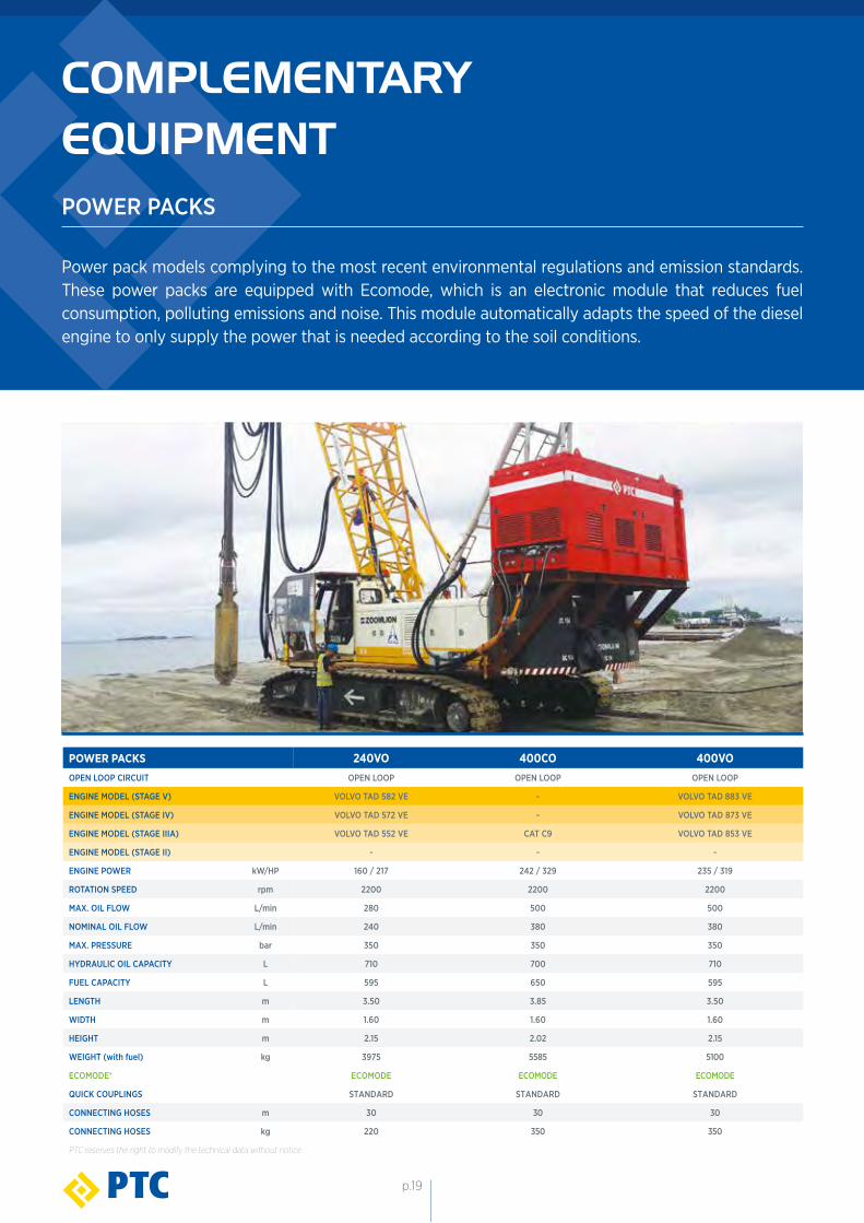
COMPLEMENTARYEQUIPMENTPOWER PACKS
Power pack models complying to the most recent environmental regulations and emission standards. These power packs are equipped with Ecomode, which is an electronic module that reduces fuel consumption, polluting emissions and noise. This module automatically adapts the speed of the diesel engine to only supply the power that is needed according to the soil conditions.
POWER PACKS 240VO 400CO 400VOOPEN LOOP CIRCUIT OPEN LOOP OPEN LOOP OPEN LOOP
ENGINE MODEL (STAGE V) VOLVO TAD 582 VE - VOLVO TAD 883 VE
ENGINE MODEL (STAGE IV) VOLVO TAD 572 VE - VOLVO TAD 873 VE
ENGINE MODEL (STAGE IIIA) VOLVO TAD 552 VE CAT C9 VOLVO TAD 853 VE
ENGINE MODEL (STAGE II) - - -
ENGINE POWER kW/HP 160 / 217 242 / 329 235 / 319
ROTATION SPEED rpm 2200 2200 2200
MAX. OIL FLOW L/min 280 500 500
NOMINAL OIL FLOW L/min 240 380 380
MAX. PRESSURE bar 350 350 350
HYDRAULIC OIL CAPACITY L 710 700 710
FUEL CAPACITY L 595 650 595
LENGTH m 3.50 3.85 3.50
WIDTH m 1.60 1.60 1.60
HEIGHT m 2.15 2.02 2.15
WEIGHT (with fuel) kg 3975 5585 5100
ECOMODE® ECOMODE ECOMODE ECOMODE
QUICK COUPLINGS STANDARD STANDARD STANDARD
CONNECTING HOSES m 30 30 30
CONNECTING HOSES kg 220 350 350
PTC reserves the right to modify the technical data without notice.
p.19
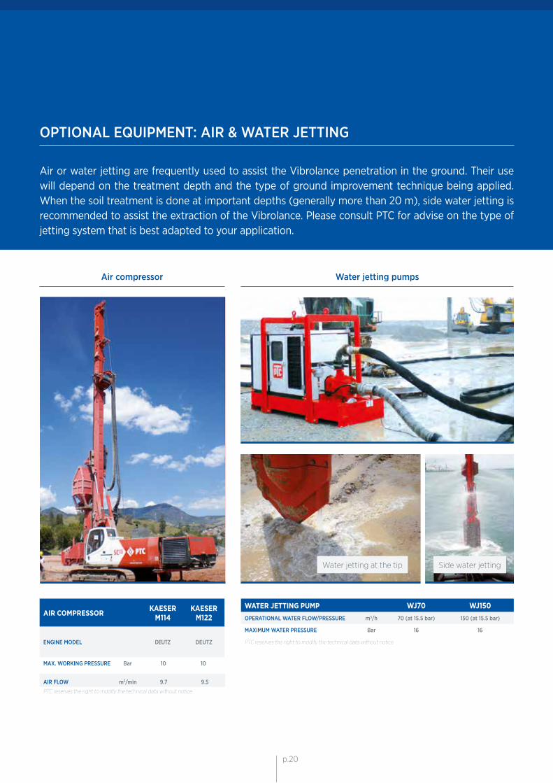
OPTIONAL EQUIPMENT: AIR & WATER JETTING
Air or water jetting are frequently used to assist the Vibrolance penetration in the ground. Their use will depend on the treatment depth and the type of ground improvement technique being applied. When the soil treatment is done at important depths (generally more than 20 m), side water jetting is recommended to assist the extraction of the Vibrolance. Please consult PTC for advise on the type of jetting system that is best adapted to your application.
AIR COMPRESSOR KAESERM114
KAESERM122
ENGINE MODEL
DEUTZ
DEUTZ
MAX. WORKING PRESSURE Bar 10 10
AIR FLOW m3/min 9.7 9.5
PTC reserves the right to modify the technical data without notice.
Side water jettingWater jetting at the tip
WATER JETTING PUMP WJ70 WJ150OPERATIONAL WATER FLOW/PRESSURE m3/h 70 (at 15.5 bar) 150 (at 15.5 bar)
MAXIMUM WATER PRESSURE Bar 16 16
PTC reserves the right to modify the technical data without notice.
Air compressor Water jetting pumps
p.20p.20
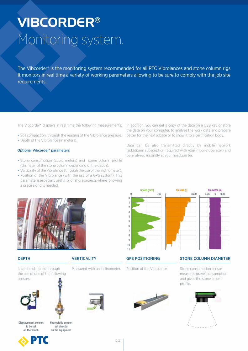
VIBCORDER®
Monitoring system.
The Vibcorder® displays in real time the following measurements:
• Soil compaction, through the reading of the Vibrolance pressure.• Depth of the Vibrolance (in meters).
Optional Vibcorder® parameters:
• Stone consumption (cubic meters) and stone column profile (diameter of the stone column depending of the depth).• Verticality of the Vibrolance (through the use of the inclinometer).• Position of the Vibrolance (with the use of a GPS system). This parameter is especially useful for offshore projects where following a precise grid is needed.
Volume (l) Diameter (m)4500 0.35 0.350 0
Speed (m/h)
0123456
8
10
7
9
11
7000
DEPTH
It can be obtained throughthe use of one of the following sensors:
VERTICALITY
Measured with an inclinometer.
STONE COLUMN DIAMETER
Stone consumption sensor measures gravel consumption and gives the stone column profile.
Displacement sensor:to be set
on the winch
Hydrostatic sensor:set directly
on the equipment
The Vibcorder® is the monitoring system recommended for all PTC Vibrolances and stone column rigs It monitors in real time a variety of working parameters allowing to be sure to comply with the job site requirements.
GPS POSITIONING
Position of the Vibrolance.
In addition, you can get a copy of the data on a USB key or store the data on your computer, to analyse the work data and prepare better for the next jobsite or to show it to a certification body.
Data can be also transmitted directly by mobile network (additional subscription required with your mobile operator) and be analysed instantly at your headquarter.
p.21

YOU ARE THE CONTRACTORPTC ground improvement equipment opens a window
of new market opportunities for contractors.
MORE AUTONOMY AND CONTROL
• You do the job, it is your equipment.• You control every aspect of the jobsite.• No hidden costs.• No more outsourcing.
SIMPLE AND COST-EFFECTIVE
• The simplicity of the vibrolance modular design and assembly, results in great reliability and ease of on-site maintenance • Easy to operate: With a short training your personnel can operate it.• Low equipment investment: You can use the Vibrolances with your regular crane or rig.
Our technical support and wide variety of ground improve-ment equipment gives you the opportunity to carry out high quality vibro compaction and stone column jobs. We provide the solution… you are in charge of the job.

WORLDWIDE NETWORKIN OVER 40 COUNTRIES
www.ptc.fayat.com
Apr
il 20
19
PTC Headquarter56 rue de Neuilly
93136 Noisy-le-Sec Cedex FranceTel: +33 1 49 42 72 95
Mail: [email protected]
PTC MIDDLE EASTJAFZA south FZS1 AH03
P.O. Box 262637, Jebel Ali-Dubai - UATel: +971 4-8863233
Mob: +971 50 340 2451Mail: [email protected]
DOWNLOAD OUR NEW MOBILE APP : PTC FAR EAST3 Tuas Avenue 16
638926 - Singapore Tel: +65 6861 7977 Tel: +65 6861 6338
Mail: [email protected]
IOS ANDROID