ground improvement techniques for railway …...ground improvement 162 issue gi1 ground improvement...
TRANSCRIPT
Proceedings of the Institution ofCivil EngineersGround Improvement 162February 2009 Issue GI1Pages 3–14doi: 10.1680/grim.2009.162.1.3
Paper 800013Received 01/11/2006Accepted 12/03/2008
Keywords: embankments/railwaysystems/rehabilitation, reclamation& renovation
Arul ArulrajahSenior Lecturer, CivilEngineering, Faculty ofEngineering and IndustrialSciences, SwinburneUniversity of Technology,Melbourne, Australia
Affendi AbdullahTechnical Consultant,Ranhill Consulting, KualaLumpur Malaysia
Myint Win BoDirector (Geo-Services),DST Consulting Engineers Inc.,Ontario, Canada
Abdelmalek BouazzaAssociate Professor,Department of CivilEngineering, MonashUniversity, Melbourne,Australia
Ground improvement techniques for railway embankments
A. Arulrajah MEngSc, PhD, FIEAust, A. Abdullah MEng, PhD, MIEM, M. W. Bo MSc, PhD, FGS, FICE, CEng, CGeol, CSci,
CEnv and A. Bouazza PhD, FIEAust
A high-speed railway project for trains of speeds of up to
160 km/h is currently being constructed between Rawang
and Bidor (110 km long) in Peninsular Malaysia. The
ground improvement methods adopted in the project
are vibro-replacement with stone columns, dry deep soil
mixing (cement columns), geogrid-reinforced piled
embankments with individual pile caps and removal/
replacement works. This paper provides a detailed
insight into the design and implementation of vibro-
replacement and the deep soil mixing treatment
methods used in the project. The use of plate bearing
tests and field instrumentation to monitor the
performance of the stone columns and soil mixing
ground treatment methods is also discussed. This paper
also provides a brief overview of other treatment
methods implemented in this high-speed railway project
such as a pile embankment with geogrids and removal/
replacement works.
NOTATION
Acol/A area ratio
Acol area of column
a area replacement ratio calculated as a ¼ (Acol/s2) for
square grid pattern of spacing, s
C cohesion of the composite system
Cu undrained shear strength of the soil
Cd comp drained cohesion of composite soil
Cu comp undrained shear strength of composite soil
ccreep col creep stress of the column
cd col drained cohesion of columns
cd soil drained cohesion of in situ soil
ch coefficient of consolidation for horizontal flow
cu col undrained cohesion of the column
cu soil undrained cohesion of the in situ soil
Dc constrained moduli of columns
Ds constrained moduli of soil
d diameter of column
de diameter of the equivalent soil cylinder
Ecol Young’s modulus of the columns
Ecomp Young’s modulus of composite soil
Esoil Young’s modulus of the in situ soil
m9 proportional load on the column
mc constant
mE constant
n2 final improvement factor
P peak angle of shear stress
Pall coll allowable load on the column
s spacing of the columns in square grid pattern
T shear stress
Th time factor for consolidation by horizontal drainage
t time
U degree of consolidation
Us degree of settlement
Up average degree of pore pressure dissipation
v volume of the element
�imp imposed stress due to dead load and live load on top
of the ground surface
ªc unit weight of column
ªf unit weight of fill
� allowable strain (ultimate)
�all col allowable creep stress
�fcol failure stress
�creep col creep stress of column
�h horizontal stress calculated at the top of soft layer
� 9vert vertical stress
�d col undrained shear stress of the column
�u col undrained shear stress of the column
�9 friction angle of the composite system
�c friction angle of column
�d col drained angle of friction of the column
�d comp drained angle of friction of composite soil
�u comp undrained angle of friction of composite soil
�d soil drained angle of friction of the in situ soil
�s friction angle of the soil layer
�u col undrained angle of friction of columns
�u soil undrained angle of friction of in situ oil
1. INTRODUCTION
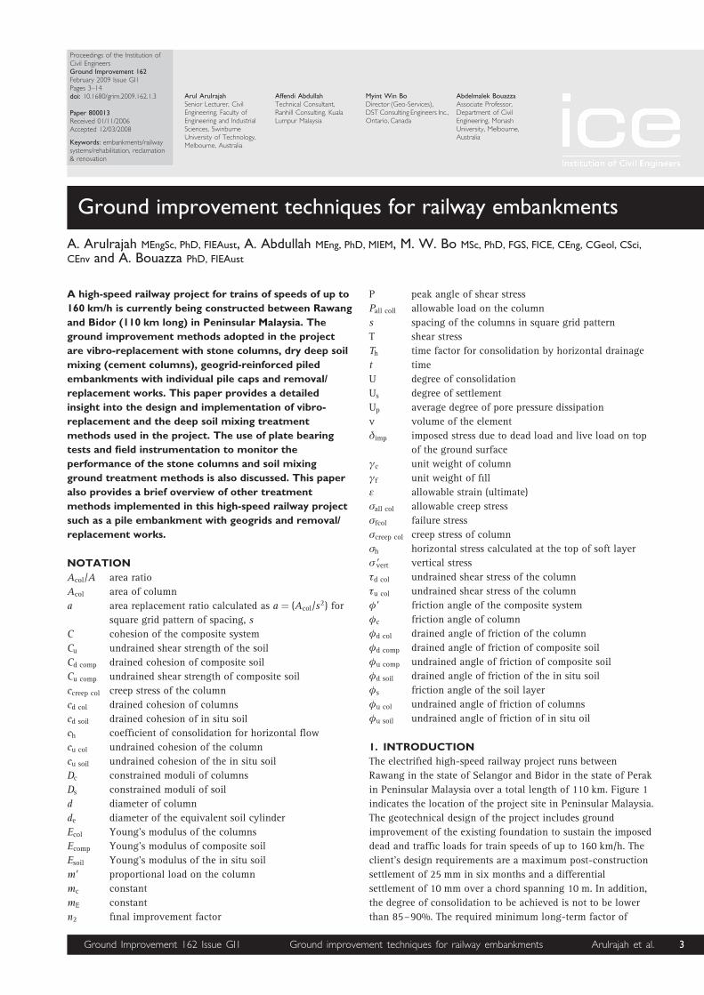
The electrified high-speed railway project runs between
Rawang in the state of Selangor and Bidor in the state of Perak
in Peninsular Malaysia over a total length of 110 km. Figure 1
indicates the location of the project site in Peninsular Malaysia.
The geotechnical design of the project includes ground
improvement of the existing foundation to sustain the imposed
dead and traffic loads for train speeds of up to 160 km/h. The
client’s design requirements are a maximum post-construction
settlement of 25 mm in six months and a differential
settlement of 10 mm over a chord spanning 10 m. In addition,
the degree of consolidation to be achieved is not to be lower
than 85–90%. The required minimum long-term factor of
Ground Improvement 162 Issue GI1 Ground improvement techniques for railway embankments Arulrajah et al. 3
safety for slope stability was 1.5. Due to the stringent
settlement restrictions and the fast-track nature of the project,
an array of ground improvement techniques had to be
implemented in locations with soft soils or loose sands on
which proposed high embankments were identified. Ground
improvement was thus required to ensure adequate
performance of the embankments in terms of settlement and
slope stability as well as completion of the project within the
required project duration.
This paper provides a detailed insight into the vibro
replacement with stone columns and dry deep soil mixing
treatment methods applied in the project. Vibro replacement
with stone columns is a subsoil improvement method in which
large-sized columns of coarse backfill material are installed in
the soil by means of special depth vibrators. Dry deep soil
mixing technology is a development of the lime–cement
column method. This paper also briefly discusses piled
embankments with geogrids and removal/replacement, which
were also treatment methods adopted in this project.
The railway embankments in the project have heights ranging
from 1 to 12 m. The top of the embankment has a minimum
width of 14.9 m for embankments less than 10 m in height and
a width of 24.9 m for embankments greater than 10 m in
height. The side slopes of the embankments have gradients of
1V:2H. Berms of 3 m width are provided on either side of
embankments which were greater than 5 m in height. The soils
encountered on the project site are highly variable mixtures of
very soft silts and clays, as well as loose sands to depths of up
to 30 m. Two approaches were needed for the treatment process
due to construction constraints: (a) treatment of the full width
of the embankment was required in locations where the new
alignments needed the construction of two new tracks; (b)
treatment at locations where a new track was to be first
constructed while the existing live track was to be later
rehabilitated. Treatment in the first stage would be for the
width of the embankment
under the new track only.
Treatment for the second
stage would include
treatment under the proposed
rehabilitated track which
would be carried out once the
train operations had been
shifted to the new live track.
2. VIBRO-
REPLACEMENT WITH
STONE COLUMNS
Vibro-replacement with stone
columns is a subsoil
improvement method in
which large-sized columns of
coarse backfill material are
installed in the soil by means
of special depth vibrators.
The stone columns and the
intervening soils form an
integrated foundation support
system having low
compressibility and improved
load-bearing capacity. Vibro-replacement with stone columns
allows for the treatment of a wide range of soils, from soft
clays to loose sands, by forming reinforcing elements of low
compressibility and high shear strength. In addition to
improving strength and deformation properties, stone columns
densify in situ soil, rapidly drain the generated excess pore
water pressures, accelerate consolidation and minimise post-
construction settlement. Normally the columns fully penetrate
the weak layer with the result that the stone column and
natural soil combination develops greatly enhanced bearing
capacity and reduced compressibility characteristics. The
method is an ideal solution for use in embankments as it
negates the effect of a ‘hard point’. The dry or wet method of
installation can be used depending on the proximity to the
existing railway track and water sources. The size of the
vibrator is around 40 cm and penetration of the vibrator into
the ground with water jetting will result in a hole of diameter
50–60 cm being created. An annular space is created between
the vibrator and the hole through which the stone is fed to the
compaction point. The up and down motion of the vibrator is
used to laterally displace the stone into the ground and at the
same time compact the stone column. This will result in the
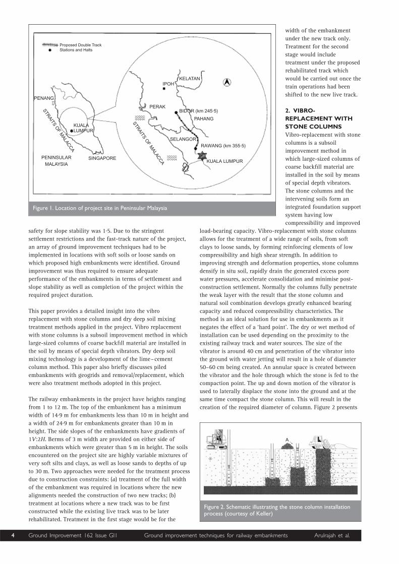
creation of the required diameter of column. Figure 2 presents
PENANG
KUALALUMPUR
SINGAPOREPENINSULARMALAYSIA
STRAITS
OF
MALAC
CA
KELATANIPOH
PERAK
STRAITS
OF
MALAC
CA
Proposed Double TrackStations and Halts
BIDOR (km 245·5)
PAHANG
SELANGORRAWANG (km 355·5)
KUALA LUMPUR
Figure 1. Location of project site in Peninsular Malaysia
A
Figure 2. Schematic illustrating the stone column installationprocess (courtesy of Keller)
4 Ground Improvement 162 Issue GI1 Ground improvement techniques for railway embankments Arulrajah et al.

a schematic diagram illustrating the installation process of
stone columns.
2.1. Stone column design methodology
The following idealised conditions are assumed in the design:
the column is based on a rigid layer; the column material is
incompressible; the design considers the group effect of the
columns and the contribution of the attributable soil
surrounding the columns; column material shears from the
beginning whereas the surrounding soil reacts elastically.
2.1.1. Settlement. Settlement under the embankment loads
was calculated using the Priebe method.1 This method gives
consideration for improvement, overburden and compatibility
control with the use of the various improvement factors. The
process is repeated for each of the various soil layers. The
reader is referred to Priebe,1 Arulrajah and Affendi2 and Bo
and Choa3 for further details on the methodology of the
settlement design for stone columns.
2.1.2. Time rate of settlement. Time rate of settlement can be
calculated by using the Terzaghi equation. The time factor for a
degree of consolidation of 90% can be obtained from the
Balaam and Booker chart,4 shown in Figure 3, which is
applicable for rigid inclusions. The equations relevant to these
calculation are as follows
t ¼ Thd2e=ch1
de ¼ 1:1283 spacing (for square grid)2
Th ¼ 0:0443
(Balaam and Booker chart for U ¼ 90%, de/d ¼ 3), where t is
time; Th is the time factor for consolidation by horizontal
drainage; de is the diameter of the equivalent soil cylinder; and
ch is the coefficient of consolidation for horizontal flow.
2.1.3. Strength properties of improved ground. Stone columns
deform until any overload has been transferred to the
neighbouring soil. The stone columns receive an increased
portion of the load, m9, which depends on the area ratio, Acol/A,
and the final improvement factor n2. The process described
below has to be repeated for each of the various soil layers
m9 ¼ n2 � 1ð Þ=n24
where m9 is the proportional load on the column.
The cohesion of the composite system depends on the
proportional area of the soil and can be calculated as follows
C9 ¼ 1� m9ð ÞCu5
where C9 is the cohesion of the composite system and Cu is the
undrained shear strength of the soil.
The shear resistance from the friction of the composite system
can be determined as follows
tan�9 ¼ m9 tan�c þ 1� m9ð Þtan�s6
where �9 is the friction angle of the composite system; �c is
the friction angle of the column; and �s is the friction angle of
the soil layer.
2.1.4. Stability. The improved cohesion and friction angle
values of the soil–column matrix is calculated from the final
improvement factor, n2, and these values are input into a slope
stability analysis program to attain the factor of safety of the
improved ground.
2.1.5. Design details. Based on the analyses of the stone
column areas, the following design parameters and design
spacing were adopted
(a) diameter of column, d ¼ 0.8 to 1.0 m
(b) unit weight of column, ªc ¼ 22 kN/m3
(c) friction angle of column, �c ¼ 408
(d) constrained moduli of columns, Dc ¼ 120 MPa
(e) constrained moduli of soil, Ds ¼ 100 3 Cu ¼ 500 3 SPT
(f) unit weight of fill, ªf ¼ 20 kN/m3
(g) traffic load ¼ 30 kN/m3.
For soft soils conditions encountered in the Rawang to Bidor
stretch, stone column spacings were generally in the range 1.8–
2.3 m for embankment heights of 5–12 m.
Predicted total settlements were of the order of 0.3–0.5 m.
Factors of safety for slope stability were greater than 1.5. Time
required for 90% degree of consolidation in the predominantly
sandy silts was less than two months. The treatment area ratio
for the stone columns varied from 13 to 20%, depending on
the design spacings for the stone columns.
2.2. Stone column installation
Arulrajah et al.,5 have described the soil conditions and soil
parameters relevant for stone column design in the project site.
The results of site investigations revealed the presence of a
wide range of soils along the track, ranging from very soft silty
0
0·2
0·4
0·6
0·8
1·00·0001 0·001 0·01 0·1 1·0
Us
Up
Barron’s solutionBiot theory
110E E1 2/ 40�
ded
RigidRaftE1
v1
E2v2kh
Smoothv v1 20·3, 0·3� �
Rigid
Th �c tr
d 2e
Figure 3. Time rate of settlement of stone columns forde/d ¼ 3 (Balaam and Booker4)
Ground Improvement 162 Issue GI1 Ground improvement techniques for railway embankments Arulrajah et al. 5
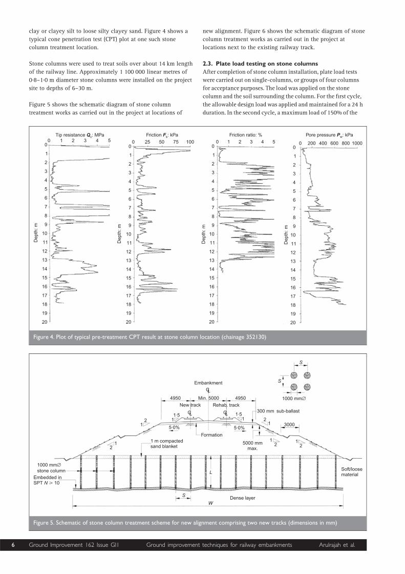
clay or clayey silt to loose silty clayey sand. Figure 4 shows a
typical cone penetration test (CPT) plot at one such stone
column treatment location.
Stone columns were used to treat soils over about 14 km length
of the railway line. Approximately 1 100 000 linear metres of
0.8–1.0 m diameter stone columns were installed on the project
site to depths of 6–30 m.
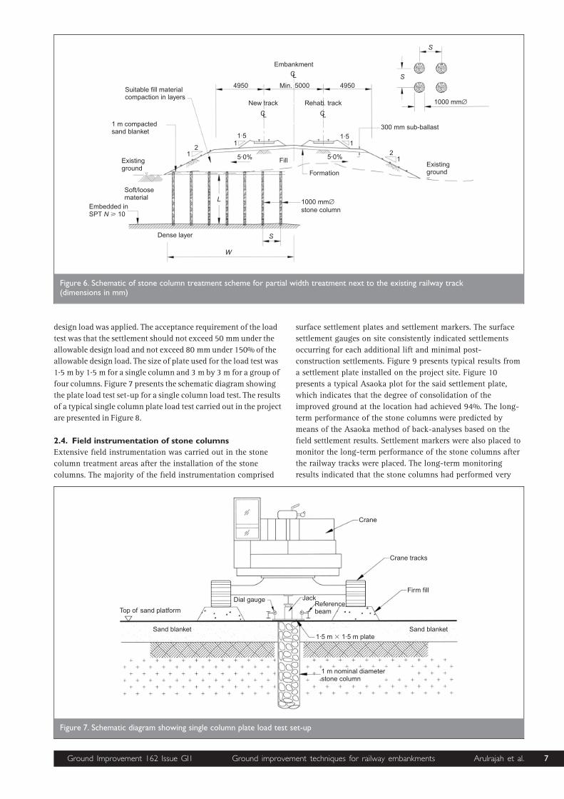
Figure 5 shows the schematic diagram of stone column
treatment works as carried out in the project at locations of
new alignment. Figure 6 shows the schematic diagram of stone
column treatment works as carried out in the project at
locations next to the existing railway track.
2.3. Plate load testing on stone columns
After completion of stone column installation, plate load tests
were carried out on single-columns, or groups of four columns
for acceptance purposes. The load was applied on the stone
column and the soil surrounding the column. For the first cycle,
the allowable design load was applied and maintained for a 24 h
duration. In the second cycle, a maximum load of 150% of the
Tip resistance : MPaQc0 1 2 3 4 5
0
1
2
3
4
5
6
7
8
9
10
11
12
13
14
15
16
17
18
19
20
Dep
th: m
0
1
2
3
4
5
6
7
8
9
10
11
12
13
14
15
16
17
18
19
20
Dep
th: m
0
1
2
3
4
5
6
7
8
9
10
11
12
13
14
15
16
17
18
19
20
Dep
th: m
0
1
2
3
4
5
6
7
8
9
10
11
12
13
14
15
16
17
18
19
20
Dep
th: m
0 25 50 75 100
Friction : kPaFs Friction ratio: %
0 1 2 3 4 5
Pore pressure : kPaPw
0 200 400 600 800 1000
Figure 4. Plot of typical pre-treatment CPT result at stone column location (chainage 352130)
Embankment
CL
4950 Min. 5000 4950 1000 mm∅
S
S
300 mm
3000
sub-ballast
12
12
5·0%
Formation
5·0%
New track
CL CL1·51
1·51 2
12
1
12
1 m compactedsand blanket
Soft/loosematerial
Dense layerW
S
L
1000 mmstone column
∅
Embedded inSPT 10N �
5000 mmmax.
Rehab. track
Figure 5. Schematic of stone column treatment scheme for new alignment comprising two new tracks (dimensions in mm)
6 Ground Improvement 162 Issue GI1 Ground improvement techniques for railway embankments Arulrajah et al.
design load was applied. The acceptance requirement of the load
test was that the settlement should not exceed 50 mm under the
allowable design load and not exceed 80 mm under 150% of the
allowable design load. The size of plate used for the load test was
1.5 m by 1.5 m for a single column and 3 m by 3 m for a group of
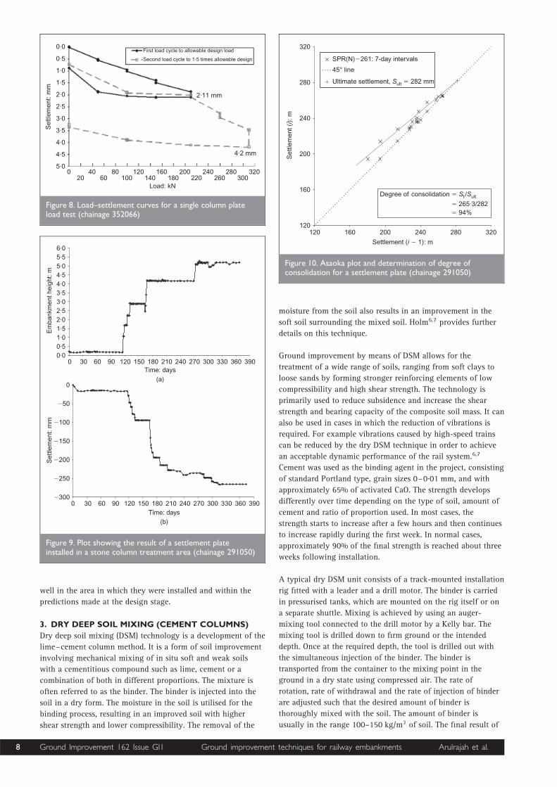
four columns. Figure 7 presents the schematic diagram showing
the plate load test set-up for a single column load test. The results
of a typical single column plate load test carried out in the project
are presented in Figure 8.
2.4. Field instrumentation of stone columns
Extensive field instrumentation was carried out in the stone
column treatment areas after the installation of the stone
columns. The majority of the field instrumentation comprised
surface settlement plates and settlement markers. The surface
settlement gauges on site consistently indicated settlements
occurring for each additional lift and minimal post-
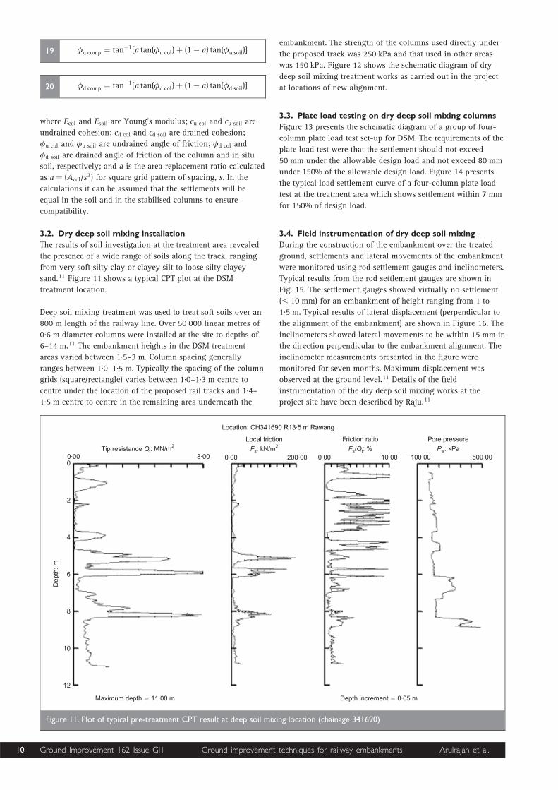
construction settlements. Figure 9 presents typical results from
a settlement plate installed on the project site. Figure 10
presents a typical Asaoka plot for the said settlement plate,
which indicates that the degree of consolidation of the
improved ground at the location had achieved 94%. The long-
term performance of the stone columns were predicted by
means of the Asaoka method of back-analyses based on the
field settlement results. Settlement markers were also placed to
monitor the long-term performance of the stone columns after
the railway tracks were placed. The long-term monitoring
results indicated that the stone columns had performed very
Embankment
CL
4950 Min. 5000 4950
1000 mm∅
S
S
300 mm sub-ballast
12
5·0%
Formation
5·0%
New track
CL CL
1·51
1·51
12
1 m compactedsand blanket
Soft/loosematerial
Dense layer
W
S
L 1000 mmstone column
∅Embedded inSPT 10N �
Rehab. track
FillExistingground
Suitable fill materialcompaction in layers
Existingground
Figure 6. Schematic of stone column treatment scheme for partial width treatment next to the existing railway track(dimensions in mm)
Crane
Crane tracks
Firm fill
Sand blanket
Jack
1·5 m 1·5 m plate�
1 m nominal diameterstone column
Sand blanket
Top of sand platform
Dial gaugeReferencebeam
Figure 7. Schematic diagram showing single column plate load test set-up
Ground Improvement 162 Issue GI1 Ground improvement techniques for railway embankments Arulrajah et al. 7
well in the area in which they were installed and within the
predictions made at the design stage.
3. DRY DEEP SOIL MIXING (CEMENT COLUMNS)
Dry deep soil mixing (DSM) technology is a development of the
lime–cement column method. It is a form of soil improvement
involving mechanical mixing of in situ soft and weak soils
with a cementitious compound such as lime, cement or a
combination of both in different proportions. The mixture is
often referred to as the binder. The binder is injected into the
soil in a dry form. The moisture in the soil is utilised for the
binding process, resulting in an improved soil with higher
shear strength and lower compressibility. The removal of the
moisture from the soil also results in an improvement in the
soft soil surrounding the mixed soil. Holm6,7 provides further
details on this technique.
Ground improvement by means of DSM allows for the
treatment of a wide range of soils, ranging from soft clays to
loose sands by forming stronger reinforcing elements of low
compressibility and high shear strength. The technology is
primarily used to reduce subsidence and increase the shear
strength and bearing capacity of the composite soil mass. It can
also be used in cases in which the reduction of vibrations is
required. For example vibrations caused by high-speed trains
can be reduced by the dry DSM technique in order to achieve
an acceptable dynamic performance of the rail system.6,7
Cement was used as the binding agent in the project, consisting
of standard Portland type, grain sizes 0–0.01 mm, and with
approximately 65% of activated CaO. The strength develops
differently over time depending on the type of soil, amount of
cement and ratio of proportion used. In most cases, the
strength starts to increase after a few hours and then continues
to increase rapidly during the first week. In normal cases,
approximately 90% of the final strength is reached about three
weeks following installation.
A typical dry DSM unit consists of a track-mounted installation
rig fitted with a leader and a drill motor. The binder is carried
in pressurised tanks, which are mounted on the rig itself or on
a separate shuttle. Mixing is achieved by using an auger-
mixing tool connected to the drill motor by a Kelly bar. The
mixing tool is drilled down to firm ground or the intended
depth. Once at the required depth, the tool is drilled out with
the simultaneous injection of the binder. The binder is
transported from the container to the mixing point in the
ground in a dry state using compressed air. The rate of
rotation, rate of withdrawal and the rate of injection of binder
are adjusted such that the desired amount of binder is
thoroughly mixed with the soil. The amount of binder is
usually in the range 100–150 kg/m3 of soil. The final result of
First load cycle to allowable design load
Second load cycle to 1·5 times allowable design
0·0
0·5
1·0
1·5
2·0
2·5
3·0
3·5
4·0
4·5
5·0
Set
tlem
ent:
mm
020
4060
80100
120140
160180
200220
240 280300
320260
Load: kN
2·11 mm
4·2 mm
Figure 8. Load–settlement curves for a single column plateload test (chainage 352066)
3903603303002702402101801501209060300·00·51·01·52·02·53·03·54·04·55·05·56·0
0Time: days
(a)
Em
bank
men
t hei
ght:
m
3903603303002702402101801501209060300Time: days
(b)
�300
�250
�200
�150
�100
�50
0
Set
tlem
ent:
mm
Figure 9. Plot showing the result of a settlement plateinstalled in a stone column treatment area (chainage 291050)
SPR(N) 261: 7-day intervals�
45° line
Ultimate settlement, 282 mmSult �
320280240200160120
160
200
240
280
320
120
Settlement ( 1): mi �
Set
tlem
ent (
): m
i
Degree of consolidation /� S St ult
� 265·3/282� 94%
Figure 10. Asaoka plot and determination of degree ofconsolidation for a settlement plate (chainage 291050)
8 Ground Improvement 162 Issue GI1 Ground improvement techniques for railway embankments Arulrajah et al.

the deep soil mixing process is a soil mass in the shape of a
cylindrical column with improved deformation and shear
resistance characteristics.
3.1. Dry deep soil mixing design methodology
The design philosophy for dry DSM is to produce a stabilised
soil mass that mechanically interacts with the surrounding
natural soil. The intention is not to produce rigid pile-like
elements which will carry all the load. This method of semi-
rigid stabilisation is often referred to as the ‘soft treatment’.
The ‘soft treatment’ can be achieved by designing with low
binder contents, which can achieve improved shear strength
values (typically undrained shear strengths ranging between
100 and 250 kPa depending on characteristics of the in situ
soil). The applied load is partly carried by the columns and
partly by the natural soil between the columns. Therefore, a too
rigidly stabilised material is not necessarily the best solution
since such a material will prevent an effective interaction and
load distribution between the stabilised soil mass and
surrounding natural soil.
The design approach and technical development for the dry
DSM in order to evaluate improved deformation and shear
strength parameters are derived from the work carried out by
Broms8,9 and the Swedish Geotechnical Society,10 and are
summarised below.
3.1.1. Stress and load on stabilised columns. The failure stress
that the column can sustain is
� f col ¼ 2cu col þ 3(�h þ 5cu soil)7
where cu col and cu soil are the undrained cohesion of the
column and in situ soil respectively and �h is the horizontal
stress calculated at the top of soft layer using K ¼ 1 and 50%
of the embankment load.
The creep stress of the column is generally calculated as
�creep col ¼ mc� f col8
The Young’s modulus of the columns can be estimated as
Ecol ¼ mE�creep col9
where mc and mE are constants and their values depend on
type of in situ soil as shown in Table 1.
To ensure that the resultant settlement on the treated ground is
less than 0.5% of the treated depth, it is a general practice to
limit the allowable stress on the column to 70% (higher values
can be used depending on the soil condition) of the creep stress
�all col ¼ 0:7�creep col10
The allowable load on the column can be calculated as
Pall col ¼ �all colAcol11
The spacing of the columns in square grid pattern can be
assessed as
s ¼ Pall col� imp
� �0:5
12
where � imp is the imposed stress on behalf of dead load and
live load on top of the ground surface.
3.1.2. Shear strength of the column. The governing equation
for shear strength is the Mohr–Coulomb equation
� ¼ c þ � 9vert tan(�)13
The undrained shear strength of the column is assumed as the
undrained cohesion of the column
�u col ¼ cu col14
where cu col is assumed as 100–250 kPa depending on the
characteristics of the binder and in situ soil.
The drained shear strength of the columns is calculated as
�d col ¼ cd col þ � 9verttan(�d col)15
where cd col is assumed as 30% of cu col and �d col is assumed as
40–458.
3.1.3. Composite soil parameters. The soil within the stabilised
block will be treated as a composite soil matrix with new soil
parameters. The Young’s modulus and undrained cohesion of
the composite soil is estimated as follows
Ecomp ¼ aEcol þ (1� a)Esoil16
cu comp ¼ acu col þ (1� a)cu soil17
cd comp ¼ acd col þ (1� a)cd soil18
Soil description mc mE
Clayey silt 0.8–0.9 150–200Silty clay 0.8 150–200Clay 0.7–0.8 150Organic clay 0.6–0.7 100Peat 0.6 50–75Silty, clayey sand 0.9 200–250
Table 1. Values of constants mc and mE applicable for deepsoil mixing design
Ground Improvement 162 Issue GI1 Ground improvement techniques for railway embankments Arulrajah et al. 9
�u comp ¼ tan�1[a tan(�u col)þ (1� a) tan(�u soil)]19
�d comp ¼ tan�1[a tan(�d col)þ (1� a) tan(�d soil)]20
where Ecol and Esoil are Young’s modulus; cu col and cu soil are
undrained cohesion; cd col and cd soil are drained cohesion;
�u col and �u soil are undrained angle of friction; �d col and
�d soil are drained angle of friction of the column and in situ
soil, respectively; and a is the area replacement ratio calculated
as a ¼ (Acol/s2) for square grid pattern of spacing, s. In the
calculations it can be assumed that the settlements will be
equal in the soil and in the stabilised columns to ensure
compatibility.
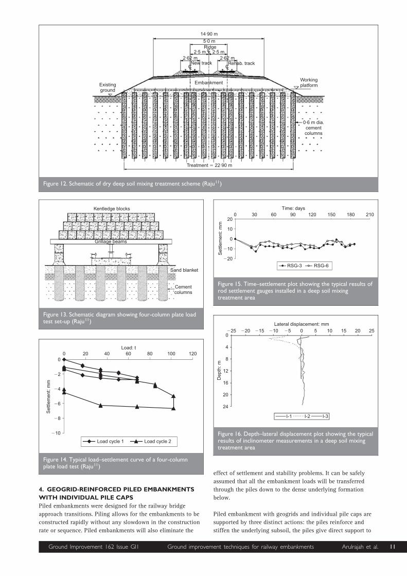
3.2. Dry deep soil mixing installation
The results of soil investigation at the treatment area revealed
the presence of a wide range of soils along the track, ranging
from very soft silty clay or clayey silt to loose silty clayey
sand.11 Figure 11 shows a typical CPT plot at the DSM
treatment location.
Deep soil mixing treatment was used to treat soft soils over an
800 m length of the railway line. Over 50 000 linear metres of
0.6 m diameter columns were installed at the site to depths of
6–14 m.11 The embankment heights in the DSM treatment
areas varied between 1.5–3 m. Column spacing generally
ranges between 1.0–1.5 m. Typically the spacing of the column
grids (square/rectangle) varies between 1.0–1.3 m centre to
centre under the location of the proposed rail tracks and 1.4–
1.5 m centre to centre in the remaining area underneath the
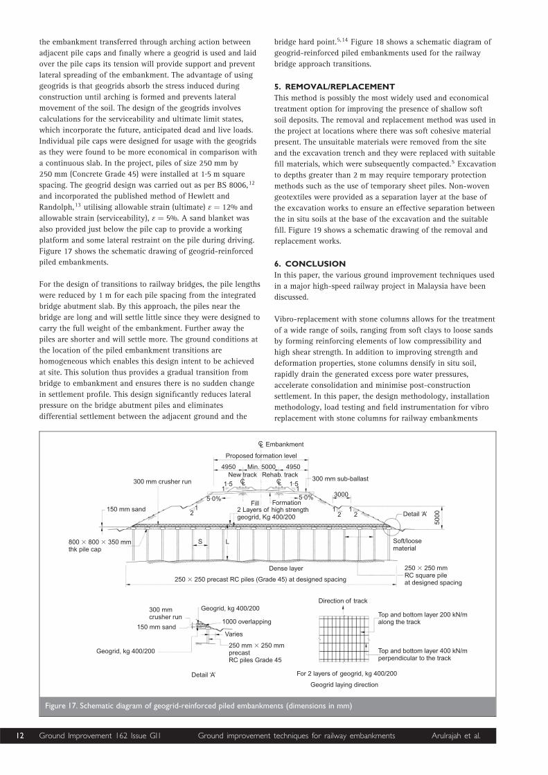
embankment. The strength of the columns used directly under
the proposed track was 250 kPa and that used in other areas
was 150 kPa. Figure 12 shows the schematic diagram of dry
deep soil mixing treatment works as carried out in the project
at locations of new alignment.
3.3. Plate load testing on dry deep soil mixing columns
Figure 13 presents the schematic diagram of a group of four-
column plate load test set-up for DSM. The requirements of the
plate load test were that the settlement should not exceed
50 mm under the allowable design load and not exceed 80 mm
under 150% of the allowable design load. Figure 14 presents
the typical load settlement curve of a four-column plate load
test at the treatment area which shows settlement within 7 mm
for 150% of design load.
3.4. Field instrumentation of dry deep soil mixing
During the construction of the embankment over the treated
ground, settlements and lateral movements of the embankment
were monitored using rod settlement gauges and inclinometers.
Typical results from the rod settlement gauges are shown in
Fig. 15. The settlement gauges showed virtually no settlement
(, 10 mm) for an embankment of height ranging from 1 to
1.5 m. Typical results of lateral displacement (perpendicular to
the alignment of the embankment) are shown in Figure 16. The
inclinometers showed lateral movements to be within 15 mm in
the direction perpendicular to the embankment alignment. The
inclinometer measurements presented in the figure were
monitored for seven months. Maximum displacement was
observed at the ground level.11 Details of the field
instrumentation of the dry deep soil mixing works at the
project site have been described by Raju.11
0·00 8·00Tip resistance : MN/mQt
2
0
2
4
6
8
10
12
Dep
th: m
Location: CH341690 R13·5 m Rawang
Maximum depth 11·00 m� Depth increment 0·05 m�
0·00 200·00
Local friction
: kN/mFs2
0·00 10·00 �100·00 500·00
Friction ratio
/ : %F Qs t
Pore pressure
: kPaPw
Figure 11. Plot of typical pre-treatment CPT result at deep soil mixing location (chainage 341690)
10 Ground Improvement 162 Issue GI1 Ground improvement techniques for railway embankments Arulrajah et al.
4. GEOGRID-REINFORCED PILED EMBANKMENTS
WITH INDIVIDUAL PILE CAPS
Piled embankments were designed for the railway bridge
approach transitions. Piling allows for the embankments to be
constructed rapidly without any slowdown in the construction
rate or sequence. Piled embankments will also eliminate the
effect of settlement and stability problems. It can be safely
assumed that all the embankment loads will be transferred
through the piles down to the dense underlying formation
below.
Piled embankment with geogrids and individual pile caps are
supported by three distinct actions: the piles reinforce and
stiffen the underlying subsoil, the piles give direct support to
14·90 m
5·0 mRidge
CL2·5 m 2·5 m2·62 m 2·62 m
New track Rehab. trackCL CL
EmbankmentExistingground
Treatment 22·90 m�
0·6 m dia.cementcolumns
Workingplatform
Figure 12. Schematic of dry deep soil mixing treatment scheme (Raju11)
Kentledge blocks
Grillage beams
Sand blanket
Cementcolumns
Figure 13. Schematic diagram showing four-column plate loadtest set-up (Raju11)
210180150120906030
�20
�10
0
10
200
Time: days
Set
tlem
ent:
mm
RSG-3 RSG-6
Figure 15. Time–settlement plot showing the typical results ofrod settlement gauges installed in a deep soil mixingtreatment area
12010080604020
�10
�8
�6
�4
�2
00
Load: t
Set
tlem
ent:
mm
Load cycle 1 Load cycle 2
Figure 14. Typical load–settlement curve of a four-columnplate load test (Raju11)
Lateral displacement: mm�25 �20 �15 �10 �5 0 5 10 15 20 250
4
8
12
16
20
24
Dep
th: m
I-1 I-2 I-3
Figure 16. Depth–lateral displacement plot showing the typicalresults of inclinometer measurements in a deep soil mixingtreatment area
Ground Improvement 162 Issue GI1 Ground improvement techniques for railway embankments Arulrajah et al. 11
the embankment transferred through arching action between
adjacent pile caps and finally where a geogrid is used and laid
over the pile caps its tension will provide support and prevent
lateral spreading of the embankment. The advantage of using
geogrids is that geogrids absorb the stress induced during
construction until arching is formed and prevents lateral
movement of the soil. The design of the geogrids involves
calculations for the serviceability and ultimate limit states,
which incorporate the future, anticipated dead and live loads.
Individual pile caps were designed for usage with the geogrids
as they were found to be more economical in comparison with
a continuous slab. In the project, piles of size 250 mm by
250 mm (Concrete Grade 45) were installed at 1.5 m square
spacing. The geogrid design was carried out as per BS 8006,12
and incorporated the published method of Hewlett and
Randolph,13 utilising allowable strain (ultimate) � ¼ 12% and
allowable strain (serviceability), � ¼ 5%. A sand blanket was
also provided just below the pile cap to provide a working
platform and some lateral restraint on the pile during driving.
Figure 17 shows the schematic drawing of geogrid-reinforced
piled embankments.
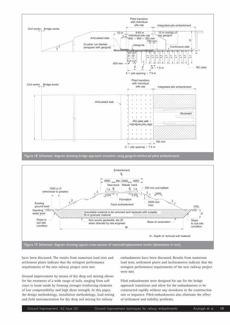
For the design of transitions to railway bridges, the pile lengths
were reduced by 1 m for each pile spacing from the integrated
bridge abutment slab. By this approach, the piles near the
bridge are long and will settle little since they were designed to
carry the full weight of the embankment. Further away the
piles are shorter and will settle more. The ground conditions at
the location of the piled embankment transitions are
homogeneous which enables this design intent to be achieved
at site. This solution thus provides a gradual transition from
bridge to embankment and ensures there is no sudden change
in settlement profile. This design significantly reduces lateral
pressure on the bridge abutment piles and eliminates
differential settlement between the adjacent ground and the
bridge hard point.5,14 Figure 18 shows a schematic diagram of
geogrid-reinforced piled embankments used for the railway
bridge approach transitions.
5. REMOVAL/REPLACEMENT
This method is possibly the most widely used and economical
treatment option for improving the presence of shallow soft
soil deposits. The removal and replacement method was used in
the project at locations where there was soft cohesive material
present. The unsuitable materials were removed from the site
and the excavation trench and they were replaced with suitable
fill materials, which were subsequently compacted.5 Excavation
to depths greater than 2 m may require temporary protection
methods such as the use of temporary sheet piles. Non-woven
geotextiles were provided as a separation layer at the base of
the excavation works to ensure an effective separation between
the in situ soils at the base of the excavation and the suitable
fill. Figure 19 shows a schematic drawing of the removal and
replacement works.
6. CONCLUSION
In this paper, the various ground improvement techniques used
in a major high-speed railway project in Malaysia have been
discussed.
Vibro-replacement with stone columns allows for the treatment
of a wide range of soils, ranging from soft clays to loose sands
by forming reinforcing elements of low compressibility and
high shear strength. In addition to improving strength and
deformation properties, stone columns densify in situ soil,
rapidly drain the generated excess pore water pressures,
accelerate consolidation and minimise post-construction
settlement. In this paper, the design methodology, installation
methodology, load testing and field instrumentation for vibro
replacement with stone columns for railway embankments
EmbankmentCL
CL CL
Proposed formation level
4950 Min. 5000 4950New track Rehab. track
300 mm sub-ballast
3000
1·511
1·5
5·0% 5·0%Fill Formation
300 mm crusher run
150 mm sand
800 800 350 mmthk pile cap
� � S L
2 Layers of high strengthgeogrid, Kg 400/200
12
12
12 Detail ‘A’
5000
Soft/loosematerial
250 250 mmRC square pileat designed spacing
�Dense layer
250 250 precast RC piles (Grade 45) at designed spacing�
300 mmcrusher run
150 mm sand
Geogrid, kg 400/200
Detail ‘A’
Geogrid, kg 400/200
1000 overlapping
Varies
250 mm 250 mmprecastRC piles Grade 45
�
Direction of track
Top and bottom layer 200 kN/malong the track
Top and bottom layer 400 kN/mperpendicular to the track
For 2 layers of geogrid, kg 400/200
Geogrid laying direction
Figure 17. Schematic diagram of geogrid-reinforced piled embankments (dimensions in mm)
12 Ground Improvement 162 Issue GI1 Ground improvement techniques for railway embankments Arulrajah et al.
have been discussed. The results from numerous load tests and
settlement plates indicate that the stringent performance
requirements of the new railway project were met.
Ground improvement by means of dry deep soil mixing allows
for the treatment of a wide range of soils, ranging from soft
clays to loose sands by forming stronger reinforcing elements
of low compressibility and high shear strength. In this paper,
the design methodology, installation methodology, load testing
and field instrumentation for dry deep soil mixing for railway
embankments have been discussed. Results from numerous
load tests, settlement plates and inclinometers indicate that the
stringent performance requirements of the new railway project
were met.
Piled embankments were designed for use for the bridge
approach transitions and allow for the embankments to be
constructed rapidly without any slowdown in the construction
rate or sequence. Piled embankments also eliminate the effect
of settlement and stability problems.
Bridge worksCivil works
Bridge worksCivil works
Articulated slab
31
Articulated slab
Crusher run blanket(wrapped with geogrid)
10 m5 m
8·65 m
Piled transitionwith individual
pile cap Integrated pile embankment
10 m overlap oftop geogrid
H
Continuous slab
750 mm
Geogrids
Individual pile cap800 800 350 mm� �
400 mm
5 pile spacing 7·5 m� �
S 1·5 m� RC piles
L1L1L1L1L1L1L1L1L1L1
1 m
1 m
L26
m�
L26
m�
Piled transitionwith individual
pile cap Integrated pile embankment
5 pile spacing 7·5 m��
750 mm
Abutment
RC piles withindividual pile caps
Figure 18. Schematic diagram showing bridge approach transition using geogrid-reinforced piled embankments
5.0% 5.0%
EmbankmentCL
4950 Min. 5000 4950
New track Rehab. trackCL CL1·5
11·5
1300 mm sub-ballast
3000
5000 mmmax.
Formation
Track embankment
21
21
OGL
D
Slopeto suit sitecondition
Base of excavation
D - Depth of removal soft material
21
21
1500 or(whichever is greater)
D
Existingground level
Standingwater level
Slope tosuit sitecondition
Non-woven geotextile, ket 20when directed by site engineer.
W
Unsuitable material to be removed and replaced with suitablefill or granular material
Figure 19. Schematic diagram showing typical cross-section of removal/replacement works (dimensions in mm)
Ground Improvement 162 Issue GI1 Ground improvement techniques for railway embankments Arulrajah et al. 13
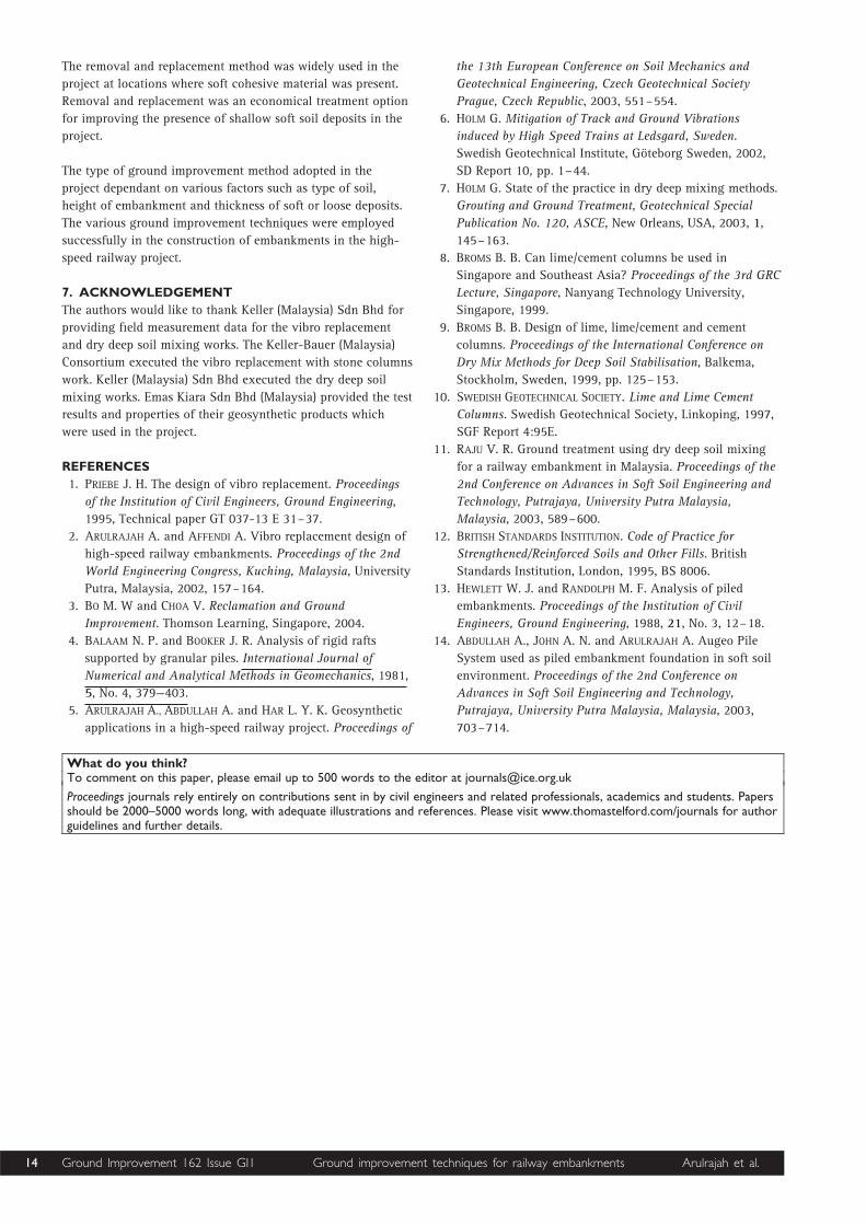
The removal and replacement method was widely used in the
project at locations where soft cohesive material was present.
Removal and replacement was an economical treatment option
for improving the presence of shallow soft soil deposits in the
project.
The type of ground improvement method adopted in the
project dependant on various factors such as type of soil,
height of embankment and thickness of soft or loose deposits.
The various ground improvement techniques were employed
successfully in the construction of embankments in the high-
speed railway project.
7. ACKNOWLEDGEMENT
The authors would like to thank Keller (Malaysia) Sdn Bhd for
providing field measurement data for the vibro replacement
and dry deep soil mixing works. The Keller-Bauer (Malaysia)
Consortium executed the vibro replacement with stone columns
work. Keller (Malaysia) Sdn Bhd executed the dry deep soil
mixing works. Emas Kiara Sdn Bhd (Malaysia) provided the test
results and properties of their geosynthetic products which
were used in the project.
REFERENCES
1. PRIEBE J. H. The design of vibro replacement. Proceedings
of the Institution of Civil Engineers, Ground Engineering,
1995, Technical paper GT 037-13 E 31–37.
2. ARULRAJAH A. and AFFENDI A. Vibro replacement design of
high-speed railway embankments. Proceedings of the 2nd
World Engineering Congress, Kuching, Malaysia, University
Putra, Malaysia, 2002, 157–164.
3. BO M. W and CHOA V. Reclamation and Ground
Improvement. Thomson Learning, Singapore, 2004.
4. BALAAM N. P. and BOOKER J. R. Analysis of rigid rafts
supported by granular piles. International Journal of
Numerical and Analytical Methods in Geomechanics, 1981,
5, No. 4, 379—403.
5. ARULRAJAH A., ABDULLAH A. and HAR L. Y. K. Geosynthetic
applications in a high-speed railway project. Proceedings of
the 13th European Conference on Soil Mechanics and
Geotechnical Engineering, Czech Geotechnical Society
Prague, Czech Republic, 2003, 551–554.
6. HOLM G. Mitigation of Track and Ground Vibrations
induced by High Speed Trains at Ledsgard, Sweden.
Swedish Geotechnical Institute, Goteborg Sweden, 2002,
SD Report 10, pp. 1–44.
7. HOLM G. State of the practice in dry deep mixing methods.
Grouting and Ground Treatment, Geotechnical Special
Publication No. 120, ASCE, New Orleans, USA, 2003, 1,
145–163.
8. BROMS B. B. Can lime/cement columns be used in
Singapore and Southeast Asia? Proceedings of the 3rd GRC
Lecture, Singapore, Nanyang Technology University,
Singapore, 1999.
9. BROMS B. B. Design of lime, lime/cement and cement
columns. Proceedings of the International Conference on
Dry Mix Methods for Deep Soil Stabilisation, Balkema,
Stockholm, Sweden, 1999, pp. 125–153.
10. SWEDISH GEOTECHNICAL SOCIETY. Lime and Lime Cement
Columns. Swedish Geotechnical Society, Linkoping, 1997,
SGF Report 4:95E.
11. RAJU V. R. Ground treatment using dry deep soil mixing
for a railway embankment in Malaysia. Proceedings of the
2nd Conference on Advances in Soft Soil Engineering and
Technology, Putrajaya, University Putra Malaysia,
Malaysia, 2003, 589–600.
12. BRITISH STANDARDS INSTITUTION. Code of Practice for
Strengthened/Reinforced Soils and Other Fills. British
Standards Institution, London, 1995, BS 8006.
13. HEWLETT W. J. and RANDOLPH M. F. Analysis of piled
embankments. Proceedings of the Institution of Civil
Engineers, Ground Engineering, 1988, 21, No. 3, 12–18.
14. ABDULLAH A., JOHN A. N. and ARULRAJAH A. Augeo Pile
System used as piled embankment foundation in soft soil
environment. Proceedings of the 2nd Conference on
Advances in Soft Soil Engineering and Technology,
Putrajaya, University Putra Malaysia, Malaysia, 2003,
703–714.
What do you think?To comment on this paper, please email up to 500 words to the editor at [email protected]
Proceedings journals rely entirely on contributions sent in by civil engineers and related professionals, academics and students. Papersshould be 2000–5000 words long, with adequate illustrations and references. Please visit www.thomastelford.com/journals for authorguidelines and further details.
14 Ground Improvement 162 Issue GI1 Ground improvement techniques for railway embankments Arulrajah et al.