ground liner etl - designplan
TRANSCRIPT

GROUND LINER®ETLInstallation Instrucions
Designplan Lighting, Inc., 79 Trenton Ave., Frenchtown NJ, 08825. T.908-996-7710 F.908-996-7042

INDEX
34569131415
REFERENCES
TECHNICAL DATA MEASURES INDICATIONS INSTALLATION
EXTRACTION TOOL RGB CONNECTIONS MONOCOLOR CONNECTIONS SAFETY PRECAUTIONS 17
Gro
und
Line
r®ET
L TE
CH
NIC
AL
GU
IDE
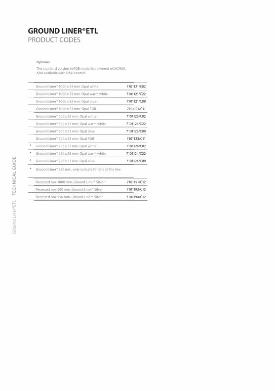
GROUND LINER®ETLPRODUCT CODES
Ground Liner® 1000 x 33 mm. Opal white 7101121/C02
Ground Liner® 1000 x 33 mm. Opal warm white 7101121/C22
Ground Liner® 1000 x 33 mm. Opal blue 7101121/C09
Ground Liner® 1000 x 33 mm. Opal RGB 7101121/C11
Ground Liner® 500 x 33 mm. Opal white 7101123/C02
Ground Liner® 500 x 33 mm. Opal warm white 7101123/C22
Ground Liner® 500 x 33 mm. Opal blue 7101123/C09
Ground Liner® 500 x 33 mm. Opal RGB 7101123/C11
* Ground Liner® 250 x 33 mm. Opal white 7101124/C02
* Ground Liner® 250 x 33 mm. Opal warm white 7101124/C22
* Ground Liner® 250 x 33 mm. Opal blue 7101124/C09
* Ground Liner® 250 mm. only suitable for end of the line
Recessed box 1000 mm. Ground Liner® Silver 7101191/C12
Recessed box 500 mm. Ground Liner® Silver 7101193/C12
Recessed box 250 mm. Ground Liner® Silver 7101194/C12
Options
The standard version in RGB model is delivered with DMX. Also available with DALI control.
Gro
und
Line
r®ET
L TE
CH
NIC
AL
GU
IDE
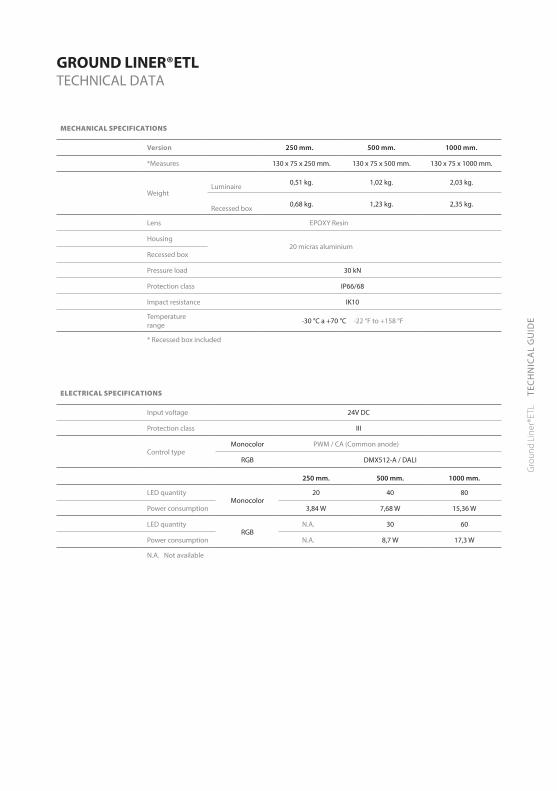
GROUND LINER®ETLTECHNICAL DATA
MECHANICAL SPECIFICATIONS
Version 250 mm. 500 mm. 1000 mm.
*Measures 130 x 75 x 250 mm. 130 x 75 x 500 mm. 130 x 75 x 1000 mm.
WeightLuminaire 0,51 kg. 1,02 kg. 2,03 kg.
Recessed box 0,68 kg. 1,23 kg. 2,35 kg.
Lens EPOXY Resin
Housing20 micras aluminium
Recessed box
Pressure load 30 kN
Protection class IP66/68
Impact resistance IK10
Temperature range -30 °C a +70 °C -22 °F to +158 °F
* Recessed box included
ELECTRICAL SPECIFICATIONS
Input voltage 24V DC
Protection class III
Control typeMonocolor PWM / CA (Common anode)
RGB DMX512-A / DALI
250 mm. 500 mm. 1000 mm.
LED quantityMonocolor
20 40 80
Power consumption 3,84 W 7,68 W 15,36 W
LED quantityRGB
N.A. 30 60
Power consumption N.A. 8,7 W 17,3 W
N.A. Not available

Gro
und
Line
r®ET
L TE
CH
NIC
AL
GU
IDE
GROUND LINER®ETL DIMENSIONS
Inner Body
Outer Body
1000 / 500 / 250 mm.(39,4 / 19,7 / 9,85 in)
35 mm.(1,38 in)
75 mm.(2,95 in)
125
mm
.(4
,92
in)
30 mm.(1,18 in)
1000 / 500 / 250 mm.(39,4 / 19,7 / 9,85 in)
43 m
m.
(1,6
9 in
)
1000 / 500 / 250 mm.(39,4 / 19,7 / 9,85 in)
35 mm.(1,38 in)
75 mm.(2,95 in)
125
mm
.(4
,92
in)
30 mm.(1,18 in)
1000 / 500 / 250 mm.(39,4 / 19,7 / 9,85 in)
43 m
m.
(1,6
9 in
)
Gro
und
Line
r®ET
L TE
CH
NIC
AL
GU
IDE
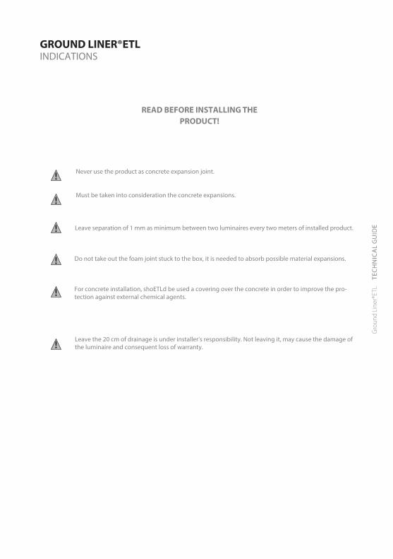
GROUND LINER®ETL INDICATIONS
Never use the product as concrete expansion joint.
Must be taken into consideration the concrete expansions.
Leave separation of 1 mm as minimum between two luminaires every two meters of installed product.
Do not take out the foam joint stuck to the box, it is needed to absorb possible material expansions.
For concrete installation, shoETLd be used a covering over the concrete in order to improve the pro-tection against external chemical agents.
Leave the 20 cm of drainage is under installer’s responsibility. Not leaving it, may cause the damage of the luminaire and consequent loss of warranty.
READ BEFORE INSTALLING THE PRODUCT!

Gro
und
Line
r®ET
L TE
CH
NIC
AL
GU
IDE
11
2
3
Place it to avoid entrance of dirtNOT INCLUDED
GROUND LINER®ETL INSTALLATION

Gro
und
Line
r®ET
L TE
CH
NIC
AL
GU
IDE
1
2
3
GROUND LINER®ETL INSTALLATION

Gro
und
Line
r®ET
L TE
CH
NIC
AL
GU
IDE
Pour the concrete carefully around the luminaires
Remove cover
GROUND LINER®ETL INSTALLATION

GLETL.IMT-152.V1.11.
Gro
und
Line
r®ET
L TE
CH
NIC
AL
GU
IDE
Concrete detail
Luminaire positionLuminaire place
5mm
FILL UP WITH CONCRETE UP TO 5mm OVER THE BOX LEVEL
20 c
m MINIMUM
DRAINAGE
GROUND LINER®ETLINSTALLATION

Gro
und
Line
r®ET
L TE
CH
NIC
AL
GU
IDE
Once the luminaire has been placed, the lateral sides must be sealed with BOSTIK POLIURETANE for OUTDOOR applications
GROUND LINER®ETL INSTALLATION

GLETL.IMT-152.V1.13.
Gro
und
Line
r®ET
L TE
CH
NIC
AL
GU
IDE
Next Luminaire
Next Luminaire
GROUND LINER®ETL INSTALLATION

Gro
und
Line
r®ET
L TE
CH
NIC
AL
GU
IDE
Centric extraction
End extraction
GROUND LINER®ETLEXTRACTION TOOL

Gro
und
Line
r®ET
L TE
CH
NIC
AL
GU
IDE
GROUND LINER®ETLRGB CONNECTIONS
M030360
DMXOutput 1
DMXOutput
234 DMX 512-A up to 5 luminaires
DMX 512-A more than 5 luminaires
DMX Controller
DMX Ampli�er
MCIGRUPO
DMX CONTROLLER
MCIGRUPO
DMX CONTROLLER
DMX Controller
DATA
A
B
PSU 24V DC - 320W
B24V DC
24+ (White)GND- (Black)DMX+ (Brown)DMX- (Blue)
Maximum 5 luminaires of 1m. per DMX output with PSU 24V DC - 320WMaximum 100 meters from controller to �rst luminaireMaximum 100 meters from ampli�er to last luminaire
Maximum 5 luminaires of 1m. per DMX controller with PSU 24V DC - 150WMaximum 100 meters from controller to �rst luminaire
Follow connection diagram type for DALI installations
This connection to bemade inside outer body
This connection to bemade inside outer body
This connection to bemade inside outer body
M030360
M030360
Remote power supplyto be connected to fixtures inside a nema style (or equal) enclosure (by others), using appropriate wirenuts.
NOTE:All wiring outside of outer bodiesmust be run thru conduit!
Gro
und
Line
r®ET
L TE
CH
NIC
AL
GU
IDE
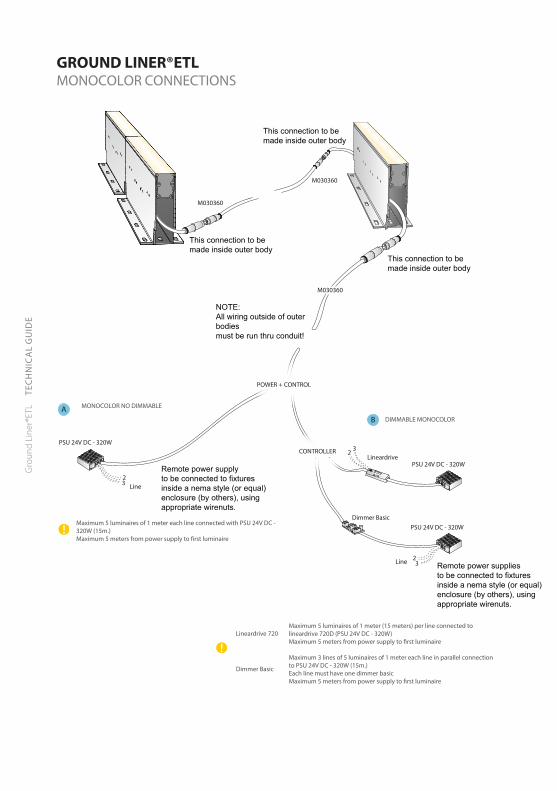
CONTROLLER
DIMMABLE MONOCOLOR
MONOCOLOR NO DIMMABLE
Dimmer Basic
Dimmer Basic
Lineardrive 720
Lineardrive
PSU 24V DC - 320W
PSU 24V DC - 320W
PSU 24V DC - 320W
AB
Maximum 5 luminaires of 1 meter (15 meters) per line connected to lineardrive 720D (PSU 24V DC - 320W)Maximum 5 meters from power supply to �rst luminaire
Maximum 3 lines of 5 luminaires of 1 meter each line in parallel connection to PSU 24V DC - 320W (15m.)Each line must have one dimmer basicMaximum 5 meters from power supply to �rst luminaire
M030360
Maximum 5 luminaires of 1 meter each line connected with PSU 24V DC - 320W (15m.) Maximum 5 meters from power supply to �rst luminaire
POWER + CONTROL
32
Line 23
Line23
GROUND LINER®ETLMONOCOLOR CONNECTIONS
This connection to bemade inside outer body
This connection to bemade inside outer body
This connection to bemade inside outer body
M030360
M030360
NOTE:All wiring outside of outer bodiesmust be run thru conduit!
Remote power suppliesto be connected to fixtures inside a nema style (or equal) enclosure (by others), using appropriate wirenuts.
Remote power supplyto be connected to fixtures inside a nema style (or equal) enclosure (by others), using appropriate wirenuts.

Gro
und
Line
r®ET
L TE
CH
NIC
AL
GU
IDE
max. 5 uds. x1m
max. 5 uds. x1m max. 5 uds. x1m
max. 5 uds. x1m
24V DC-PWM (Blue)
GND- (Black)24+ (White)24+ (Brown)
+
Steady Light
Lineardrive 720D DMX/DALI/0-10V 24V DC
Power Supply24 V DC 320 W
+-
Next line
24V DC-PWM (Blue)
GND- (Black)24+ (White)24+ (Brown)
+
LINEARdrive 720D
Group 1GND 1
GND 2
GND 3
GND 4
DMX +
+-
DMX -DMX shieldLEDSync +
Dali INDali INDali OUTDali OUT
LEDSync -LEDSync shield
Group 2
Group 3
Group 4
M050206Power Supply24 V DC 320 W
Next line
+ +- -
GROUND LINER®ETLMONOCOLOR CONNECTIONS
Gro
und
Line
r®ET
L TE
CH
NIC
AL
GU
IDE
GROUND LINER®ETL SAFETY PRECAUTIONS
Use as directed
This product serves exclusively lighting purposes and may:• Expose to strong mechanical loads or strong contamination.• Only be installed and operated after a condition inspection if the product is dirty or has beenmoistened through storage.
• Not be modified or converted.
If these points named above are not adhered to, a short circuit or electrical shock may occur!
InstallationThe complete installation must be done by an electrical expert or a specialized maintenance team, who is familiar with valid directives.
Attention: Switch off power of the mains supply or respectively of the connection lead before doing any works.
Use only parts, which are supplied with the product or are described as accessories! Otherwise the product or the installation might not be sufficiently safe!
Indication for the installer: In case you do not install a completely supplied system (with transformer), you are considered a “manufacturer” by the low-voltage directive. In this case you are required to ensure the conformity of the whole system and declare it by attaching the CE-sign.
Installation placeMake sure that the product is mounted on a stable, even and tilt-fixed background. Note the minimum distances in the ceiling.
Attention: Do not cover the product, especially not with insETLating materials.
Operation - Information for the userOperate the product only if it is working correctly. Switch off the product with a malfunction immediately and operate it again only after examination by an electrical specialist. This is the case, when:• Visible damages appear.• The product does not work.• Smoke, steam or crackling sounds appear.• An overheating is recognisable.Repairs of the product or work on mains voltage-prominent sections may only be carried out by qualified electricians.
Attention: Exists mortal danger from an electric shock!
How to avoid failure and fire risk• Do not cover the product - provide free air circETLation!• Do not hang or fasten anything on the product, especially no decoration.• Never let children play unsupervised with electric products!• Children can not always estimate dangers in dealing with electric energy correctly.
Disconnect the product from power, before you…• Clean or maintain the product.• Do any works on the product or its components (electric expert).

IMT-152 v.01Ground Liner®ETL
Designplan Lighting, Inc., 79 Trenton Ave., Frenchtown NJ, 08825. T.908-996-7710 F.908-996-7042