grounding and bonding according to the 2011 nec - ut
TRANSCRIPT

7/27/2019 Grounding and Bonding According to the 2011 NEC - UT
http://slidepdf.com/reader/full/grounding-and-bonding-according-to-the-2011-nec-ut 1/32
Grounding and Bonding According to the 2011 NEC - UT Author: David Burtt
Grounding and Bonding According to the 2011 NEC - UT
Question 1: 250.24 (A) Grounding Service-Supplied Alternating-Current Systems. SystemGrounding Connections.
Question ID#: 24
A grounding electrode conductor must be connecte
to the grounded service conductor at each service.
Every building that is supplied by a grounded AC service must have a groundingelectrode. A grounding electrode conductor connects the grounding electrode to thegrounded service conductor.
The connection from the grounded conductor at the service to the groundingelectrode will limit the voltage to ground if the service conductors are hit by lightningor come in accidental contact with high voltage wires. The connection to thegrounding electrode will also stabilize the voltage to ground throughout the buildingwiring system.
A grounded AC service requires a grounding electrode. Since the groundingelectrode is in contact with the earth, and the grounding electrode conductor isconnected to the service grounded conductor, the building AC service has a directphysical connection with the earth.
Question 1: Which of the following conductors is used to ground a service-supplied alternating-current system? A: The grounded conductor in a multiwire branch circuit.B: The ungrounded conductor in a sub-panel feeder.C: The equipment grounding conductor in a main distribution panel.D: The grounding electrode conductor in a service enclosure.
Grounding and Bonding at Transformers
Question 2: 250.52(A)(4)–(8) Ground Ring; Rod and Pipe Electrodes; Plate Electrodes; Other LocalMetal Underground Systems or Structures.
Question ID#: 24
Ground rods, rings, plates, and local underground
systems are permitted to be used as grounding
electrodes.
Other electrodes that are permitted for grounding include: ground rings, rod and pipeelectrodes, plate electrodes and metal underground structures that are not bonded toa metal water pipe.
Ground rings are usually used on commercial buildings with large amounts ofcommunication and computer gear. The minimum requirement for a ground ring is atleast 20 ft. of bare copper No. 2 AWG. Most ground rings use considerably largerwire. A 3/0 AWG ground ring is not uncommon.
Rod and pipe electrodes must be at least 8 ft. in length. Copper or zinc coated steelrods must be at least 5/8 inch in diameter.
Plate electrodes are not common, but when used must have at least 2 square ft. ofarea exposed to the earth. Steel and iron plates must be at least 1/4 inch thick.
Other local metal underground systems or structures include underground pipingsystems, underground tanks, and underground metal well casings that are notbonded to a metal water pipe.
Section 250.52(B) lists two structures that are not permitted to be used for grounding
Expires: 5/25/2013 Page 1 ©2013 JADE Learning, In

7/27/2019 Grounding and Bonding According to the 2011 NEC - UT
http://slidepdf.com/reader/full/grounding-and-bonding-according-to-the-2011-nec-ut 2/32
Grounding and Bonding According to the 2011 NEC - UT Author: David Burtt
electrodes:
» Underground metal gas pipe systems
» Any underground Aluminum material
Question 2: Which of the following is an acceptable grounding electrode? A: An 8 ft., 1/2 inch, unlisted copper ground rod.B: 20 ft. of underground gas piping.C: A 100 ft. ground ring using a No. 1 AWG bare cu. conductor.D: A .5 ft. x .5 ft. square steel plate.
Question 3: 250.30(A)(1) System Bonding Jumper.Question ID#: 24
The system bonding jumper is usually installed at the
transformer and connects the equipment grounding
conductors to the grounded conductor.
The system bonding jumper for a transformer is installed without a splice and is
used to connect the equipment grounding conductors of the transformer secondaryto the grounded secondary conductor. The size of the system bonding jumper isselected from Table 250.66 based on the size of the derived phase conductors.
The system bonding jumper can be installed at the transformer or at the first systemdisconnecting means. Usually the system bonding jumper is installed at thetransformer and not at the first disconnecting means.
If there is a ground fault anywhere on the system that is supplied by the secondaryof the transformer, the fault current will travel back to the transformer on the supplyside bonding jumper.
The system bonding jumper is the bridge between the equipment grounding
conductors and the grounded secondary conductor of the transformer. Fault currentravels over the system bonding jumper to the grounded conductor at the centerpoint of the transformer windings (for wye connected transformers). This lowimpedance path keeps the fault current high enough to trip the overcurrentprotective device on the faulted circuit.
Question 3: What is the purpose of the system bonding jumper? A: Connects the equipment grounding conductors of the secondary to the transformer secondary grounded conductor.B: Connects the mounting frame of the transformer coils to the transformer enclosure.C: Connects an ungrounded transformer secondary conductor to the transformer enclosure.D: Connects the primary and secondary grounded conductors together.
Expires: 5/25/2013 Page 2 ©2013 JADE Learning, In

7/27/2019 Grounding and Bonding According to the 2011 NEC - UT
http://slidepdf.com/reader/full/grounding-and-bonding-according-to-the-2011-nec-ut 3/32
Grounding and Bonding According to the 2011 NEC - UT Author: David Burtt
Question 4: 250.24(C)(2) Parallel Conductors.Question ID#: 24
When installed in parallel, the size of the grounded
conductor is based on the size of the largest phase
conductor in each raceway.
When parallel service conductors are installed in more than a single raceway, thegrounded neutral conductor will also be paralleled. The minimum size of thegrounded conductor is based on the size of the individual service conductors installedin that conduit. The grounded conductor can never be smaller than 1/0 AWGbecause the smallest service conductor that can be installed in parallel is 1/0 AWG.
In all cases the grounded conductor must be large enough to carry the unbalancedload according to 220.61.
For example: If three 500 kcmil conductors per phase were installed in 3 separateraceways with one ungrounded 500 kcmil conductor per phase in each raceway, thegrounded neutral conductor in each conduit is based on the size of a single 500 kcmilungrounded conductor in each conduit. From Table 250.66 a 1/0 AWG groundedconductor is required.
Question 4: What is the minimum size copper grounded neutral conductor that must be installed in each racewaywhen 2 raceways are installed with one, 300 kcmil copper conductor per phase in each raceway? A: 3/0 AWG.B: 2/0 AWG.
C: 1/0 AWG.D: No. 2 AWG.
Question 5: 250.35(B) Nonseparately Derived System.Question ID#: 24
If the generator is installed as a non-separately
derived system, a supply side bonding jumper mus
be installed from the generator to the disconnecting
means.
The majority of generators are installed as nonseparately derived systems. Thismeans the generator neutral is isolated from the generator frame, isolated from allother enclosures and has a solid connection to the utility service neutral in thetransfer switch.
For generators that create a three-phase, 4-wire system, the transfer switch has 3poles. For generators that create a single phase, 3-wire system, the transfer switch
has 2 poles. The generator neutral is never switched in a nonseparately derivedsystem.
A supply side bonding jumper must be installed between the generator equipmentgrounding terminal and the equipment grounding terminal or bus of the firstdisconnecting means.
In a nonseparately derived system, fault current will travel on the equipmentgrounding conductor back to the service. It will return to the generator on thegrounded neutral conductor.
Question 5: Which of the following statements best describes a permanently installed generator connected as anonseparately derived system?
A: The generator neutral is not switched in the transfer switch.B: The generator neutral is bonded to the generator enclosure.C: The generator neutral is bonded to the transfer switch enclosure.D: The generator neutral is switched when the phase conductors are switched.
Expires: 5/25/2013 Page 3 ©2013 JADE Learning, In

7/27/2019 Grounding and Bonding According to the 2011 NEC - UT
http://slidepdf.com/reader/full/grounding-and-bonding-according-to-the-2011-nec-ut 4/32
Grounding and Bonding According to the 2011 NEC - UT Author: David Burtt
Question 6: 250.30(A)(1) Grounding Separately Derived Alternating-Current Systems. SystemBonding Jumper.
Question ID#: 24
The system bonding jumper is selected from Table
250.66. Use the 12.5% rule for phase conductors
larger than 1100 kcmil cu. or 1750 kcmil al.
In most field installations, grounding and bonding is done at the transformer. If thesystem bonding jumper is installed at the transformer, then the grounding electrodeconductor must also be connected at the transformer.
When installing the system bonding jumper and the grounding electrode conductor
at the transformer, the system bonding jumper and the grounded (neutral)conductors are separated in the first disconnect.
The system bonding jumper is sized per Table 250.66 according to the size of thederived phase conductors on the secondary side of the transformer. If the derivedphase conductors are larger than 1100 kcmil cu. or 1750 kcmil al., the systembonding jumper shall be sized at not less than 12.5% of the area of the largestphase conductor.
Question 6: What is the minimum size system bonding jumper on the secondary of a 75 KVA transformer wherethe derived phase conductors are 4/0 cu.? A: No. 2 copper.B: No. 1 copper.C: 1/0 copper.D: 2/0 copper.
Question 7: 250.4(A)(5) Effective Ground-Fault Path.Question ID#: 24
Fault current returns to the source on the effective
ground-fault current path.
When a ground-fault occurs and metal equipment is energized, the circuit must bede-energized as quickly as possible. If metal equipment remains energized, it is adeadly trap waiting for someone to come in contact with it.
The safest way to deal with a ground-fault is to trip the overcurrent device thatsupplies the faulted circuit.
In order to trip the circuit breaker, the ground-fault current path must be alow-impedance circuit. An effective ground fault current path must have lowerimpedance than any other available path that fault current might take such as buildingsteel or water pipes, etc. A low-impedance (AC resistance) path means the faultcurrent will be high enough to trip the overcurrent device. If the fault-current path isnot low-impedance, the fault-current will be too low to trip the circuit breaker, but highenough to kill a person.
An effective ground-fault current path must be capable of carrying the maximumground-fault current that it is likely to see. When equipment grounding conductorsare sized according to Table 250.122 and grounding electrode conductors are sizedaccording to Table 250.66, they are large enough to carry likely levels of fault current.
Question 7: The effective ground-fault current path must: A: Provide a path for normal unbalanced (neutral) current.B: Be installed without a splice.C: Have low impedance and be big enough to carry available fault current.D: Be connected to the grounded conductor on the load side of the service disconnect.
Expires: 5/25/2013 Page 4 ©2013 JADE Learning, In

7/27/2019 Grounding and Bonding According to the 2011 NEC - UT
http://slidepdf.com/reader/full/grounding-and-bonding-according-to-the-2011-nec-ut 5/32
Grounding and Bonding According to the 2011 NEC - UT Author: David Burtt
Question 8: 250.24(C) Grounded Conductor Brought to Service Equipment.Question ID#: 24
For grounded AC systems operating at less than
1000 volts, the grounded conductor must be run to
each service disconnecting means.
If the AC system supplying a building is operating at less than 1000 volts and isgrounded, the grounded conductor must be run to the building. Even if a neutralconductor is not needed to supply loads in the building, the grounded serviceconductor must still be installed from the utility source to the building servicedisconnecting means.
The reason for this is that the grounded service conductor always serves twofunctions:
1. It carries unbalanced current.2. It returns ground-fault current to the utility transformer in the event of a groundfault.
Even if the service does not need a grounded neutral conductor for the loads itsupplies, a grounded conductor is required to be installed to carry ground-faultcurrent under fault conditions.
If the grounded conductor from a grounded utility transformer is not installed to thebuilding service equipment, the ground-fault current returning to the utility transformerwould have to travel through the earth to get back to the utility transformer. The earth
should never be used as a ground-fault current path because compared to a copperor aluminum wire it is a very high resistance path.
The high resistance of the earth reduces fault-current to levels that will not trip thebreaker protecting the faulted circuit. Then the ground-fault does not clear andequipment enclosures and conduit remain energized.
Question 8: The grounded service entrance conductor for AC services operating at less than 1000 volts: A: Carries only unbalanced current.B: Is not required unless the loads served require a neutral conductor.C: Carries only ground-fault current.D: Carries both the unbalanced current and serves as a path for ground-fault current.
Question 9: 250.52(A)(2) Metal Frame of Building or Structure.Question ID#: 24
In order to be used as a grounding electrode, the
metal frame of the building must be connected to
earth.
The metal frame of a building is not a grounding electrode unless at least 10 ft. of ametal structural member is in contact with the earth, or the hold-down bolts of a stecolumn are connected to a concrete-encased electrode (rebar). The connection frothe hold-down bolts to the concrete-encased electrode can be by welding,exothermic welding or using steel tie down wires.
Installing a driven ground rod with a No. 6 cu. conductor from the ground rod to thebuilding steel is not a permitted method of connecting the building steel to earth.
Some buildings have structural members that are made from reinforced concrete,rather than steel. The frame of such a building could not be used as a groundingelectrode because there is no direct contact between a metal frame and the earth.
Question 9: The metal frame of a building is considered a grounding electrode if:
Expires: 5/25/2013 Page 5 ©2013 JADE Learning, In

7/27/2019 Grounding and Bonding According to the 2011 NEC - UT
http://slidepdf.com/reader/full/grounding-and-bonding-according-to-the-2011-nec-ut 6/32
Grounding and Bonding According to the 2011 NEC - UT Author: David Burtt
A: A structural member is in contact with the earth for 8 ft.B: The anchor bolts for a vertical column are embedded in concrete.C: The vertical and horizontal framing members are securely fastened together.D: At least 10 ft. of a single structural metal member is in direct contact with the earth.
Question 10: 250.28(D) Size.Question ID#: 24
For main and system bonding jumpers larger than
sizes listed in Table 250.66, the 12.5% rule applies
If the main bonding jumper is a screw, strap or bus provided by the manufacturer, the
size does not need to be calculated in the field. The manufacturer has already donethe calculation to get a listing from a testing agency.
If the main bonding jumper is a wire installed in the field, it is sized from Table 250.66,based on the size of the largest service entrance conductor, or the equivalent area ofparalleled service conductors.
For example, if the service entrance conductors are 3/0 cu., Table 250.66 requires aNo. 4 cu. main bonding jumper.
If the service entrance conductors are larger than 1100 kcmil cu. or 1750 kcmilaluminum (the largest size given in Table 250.66), the main bonding jumper musthave an area at least 12.5% as large as the service entrance conductors.
For example, if the service entrance conductors have a total area of 2000 kcmil, thenthe main bonding jumper must have an area at least 12.5% of 2000 kcmil. Step 1:convert from kcmil to mil. 2000 kcmil = 2,000,000 mil. Step 2: multiply by .125.2,000,000 mil x .125 = 250,000 mil, or 250 kcmil.
Question 10: What size main bonding jumper is required for 500 kcmil cu. service entrance conductors? A: 1/0 cu.B: 2/0 cu.C: 3/0 cu.D: No. 2 cu.
Question 11: 250.28(D)(2) Main Bonding Jumper for Service with More Than One Enclosure.Question ID#: 24
The size of the main bonding jumper is based on th
size of the largest phase conductor supplying each
enclosure.
When a service has more than a single service disconnect enclosure, eachdisconnect enclosure must have its own main bonding jumper. The size of the mainbonding jumper in each enclosure is based on the size of the service entranceconductors feeding that enclosure and selected from Table 250.66.
For example, a 400 amp service is supplied with 500 kcmil conductors. There aretwo, 200 amp disconnects, each one supplied with 3/0 cu. conductors. The size ofthe main bonding jumper in each disconnect is based on the 3/0 cu. wire, not the 500kcmil wire.
If the 500 kcmil service conductors fed a metal wireway or common enclosure, the
bonding jumper in the metal wireway is based on the 500 kcmil service conductors.The bonding jumper is called the equipment bonding jumper on the supply side of theservice and is sized from Table 250.66.
Question 11: If a 200 amp service that is supplied with 3/0 copper service entrance conductors has two, 100 ampservice disconnects and each is supplied with No. 3 copper conductors, what is the size of the main bondingjumpers in each 100 amp disconnect? A: No. 8 cu.B: No. 6 cu.C: No. 4 cu.
Expires: 5/25/2013 Page 6 ©2013 JADE Learning, In

7/27/2019 Grounding and Bonding According to the 2011 NEC - UT
http://slidepdf.com/reader/full/grounding-and-bonding-according-to-the-2011-nec-ut 7/32
Grounding and Bonding According to the 2011 NEC - UT Author: David Burtt
D: No. 2 cu.
Question 12: 250.24(B) Main Bonding Jumper.Question ID#: 24
The main bonding jumper connects the equipment
grounding conductors to the grounded conductors in
the service enclosure.
For grounded systems, the purpose of the main bonding jumper is to connect theequipment grounding conductors and the service-disconnect enclosure to thegrounded (neutral) service conductor within each service enclosure.
The main bonding jumper is required by section 250.24(B) to be un-spliced. Aconductor that is spliced has more resistance than an un-spliced conductor. Themain bonding jumper is part of the low-impedance path for ground-fault current andthe impedance (resistance) must be kept as low as possible.
Main bonding jumpers are permitted to be a wire, busbar, or screw as listed in250.28.
Exception No. 1 says that where more than one service disconnecting means islocated in an assembly listed for use as service equipment, only a single mainbonding jumper is required that connects the grounded conductor to the assemblyenclosure.
Question 12: Which of the following statements about the main bonding jumper is true? A: In a single UL listed switchgear assembly that has multiple disconnecting means and is listed for use as serviceequipment, a main bonding jumper must be installed in each disconnecting means.B: If the service equipment is assembled in the field and has multiple disconnecting means, each disconnect enclosure mushave a main bonding jumper.C: The main bonding jumper isolates the grounded conductor from the service enclosure(s).D: The main bonding jumper can be spliced if irreversible fittings are used.
Question 13: 250.4 General Requirements for Grounding and Bonding.Question ID#: 23
Performance requirement: An effective ground-fault
current path will cause the circuit breaker to trip.
Prescriptive requirement: System bonding jumpers
are sized per Table 250.66.
This is the most important section in all of Article 250. It is the theory of groundingand bonding at its best and clearest. The rest of Article 250 describes the how-to o
grounding and bonding. Section 250.4 describes why we ground equipment andenclosures and bond electrical systems. Section 250.4 describes the purpose ofgrounding and bonding and why it is important.
There are two types of requirements in Article 250:
» Performance requirements are general statements that explain what groundingand bonding should accomplish.
» Prescriptive requirements list how to do it.
For example, saying that non-current-carrying conductive material which is part ofelectrical equipment must be connected together is a performance requirement.Saying that metal enclosures and raceways for other than service conductors shallbe connected to the equipment grounding conductor (250.86) is a prescriptiverequirement.
Question 13: Which of the following is a performance requirement? A: Non-conductive coatings shall be removed from threads and other contact surfaces.B: The grounding electrode conductor shall be sized from Table 250.66.C: The grounded conductor shall be routed with the phase conductors.D: A low impedance ground-fault path shall be installed to facilitate the operation of the overcurrent device.
Expires: 5/25/2013 Page 7 ©2013 JADE Learning, In

7/27/2019 Grounding and Bonding According to the 2011 NEC - UT
http://slidepdf.com/reader/full/grounding-and-bonding-according-to-the-2011-nec-ut 8/32
Grounding and Bonding According to the 2011 NEC - UT Author: David Burtt
Question 14: 250.30(A)(1) Ex. 2. System Bonding Jumper.Question ID#: 24
A system bonding jumper can be installed at the
transformer and the first disconnect if it does not
create a parallel path with the grounded conductor.
This exception permits a system bonding jumper to be connected at the transformerand at the first disconnect, as long as a parallel path for normal neutral current is notset up. If a system bonding jumper is installed on both ends, the only way to preventa parallel path for neutral current between the transformer and the first disconnect isto use a nonmetallic wiring method between the transformer and the first disconnect.
If the grounded neutral conductor between the transformer and the first disconnectwas installed in metallic conduit, and grounded on both ends, then neutral currentwould travel on the neutral conductor and on the metallic conduit. This is a parallelpath and is not permitted.
Most installers do not use this exception, but as long as a nonmetallic wiring methodis installed between the transformer and the first disconnect, a system bonding
jumper that connects the grounded neutral conductor to the equipment groundingconductors can be installed at the transformer and at the first disconnect.
Question 14: Which of the following statements about the system bonding jumper is true? A: The system bonding jumper must be installed at the transformer or at the first disconnect. Never both places.B: Parallel paths for grounded neutral current are not permitted.
C: A parallel path for grounded neutral current is permitted if the neutral conductor between the transformer and firstdisconnect is installed in metallic conduit.D: The system bonding jumper must always be installed at the transformer.
Question 15: 250.30(A)(8) Bonding.Question ID#: 24
Building steel and metal water piping in the area
serviced by the transformer shall be bonded to the
grounded conductor.
The metal frame of the building and the metal water piping that are located in thearea served by the separately derived system must be bonded to the groundedconductor of the separately derived system.
The purpose of bonding the building steel and metal water lines to the groundedconductor of the separately derived system is not to connect the separately derived
system to a grounding electrode. The purpose is to provide a path for fault currentfrom conductive material like plumbing fixtures or the building steel back to theneutral of the separately derived system.
The water pipe in an area supplied by a transformer could be "high and dry." Inother words not being used as a grounding electrode. Water piping cannot be usedas a grounding electrode unless it is in direct contact with the earth for 10 feet ormore.
The water line could become energized if there was a ground fault on a circuitsupplied by the transformer, and if the piping is bonded to the transformer groundedneutral conductor, the fault current has a path back to the overcurrent devices onthe separately derived system. If the metal water piping and building steel arebonded correctly, the overcurrent device will trip and de-energize the faulted circuit.
Question 15: A transformer is located on the third floor of a multi-story building. The interior metal water pipingon the third floor: A: Is not required to be bonded to the transformer grounded conductor.B: Must be used as a grounding electrode.C: Must be bonded to the water piping on all other floors.D: Must be bonded to the transformer grounded conductor.
Expires: 5/25/2013 Page 8 ©2013 JADE Learning, In

7/27/2019 Grounding and Bonding According to the 2011 NEC - UT
http://slidepdf.com/reader/full/grounding-and-bonding-according-to-the-2011-nec-ut 9/32
Grounding and Bonding According to the 2011 NEC - UT Author: David Burtt
Question 16: 250.34(A) Portable and Vehicle-Mounted Generators. Portable Generators.Question ID#: 24
Portable generators generally do not require a
connection to a grounding electrode.
Portable generators are generators that can be easily moved from one place toanother. They can be used on construction sites for temporary power, duringremodeling and even as optional standby systems. They range in size from 750watts to 18kw.
A portable generator is not required to be connected to a grounding electrode if thegenerator supplies only the receptacles on the generator. Normally non-currentmetal parts of equipment and the equipment grounding terminals of the receptaclesmust be connected to the generator frame.
A portable generator can supply only equipment which is cord-and-plug connectedto the generator through the receptacles mounted on the generator. A portablegenerator cannot supply a fixed wiring system, such as a circuit breaker panel,without being connected through a transfer switch.
Question 16: Which of the following statements about portable generators is FALSE? A: They can be easily moved.B: They must always be connected to a grounding electrode conductor such as a driven ground rod.C: They are permitted to supply only the receptacles on the generator.
D: The grounding terminal of the receptacles must be connected to the generator frame.
Question 17: 250.32(B)(1) Buildings or Structures Supplied by a Feeder(s) or Branch Circuits(s).Question ID#: 24
If the overcurrent device is located in the generator,
the equipment grounding conductor is selected from
Table 250.122.
When a generator is installed as a nonseparately derived system, and theovercurrent protection is located in the generator, the equipment groundingconductor from the generator to the disconnecting means is sized from Table250.122. Because the derived phase conductors are protected at the generatorthey are treated as feeder conductors. Equipment grounding conductors installedwith feeders are selected from Table 250.122, based on the size of the overcurrentprotection ahead of the feeders.
For example, if a generator has overcurrent protection rated at 150 amps, theequipment grounding conductor installed with the derived phase conductorsbetween the generator and the disconnecting means cannot be smaller than No. 6cu., selected from Table 250.122.
For generators installed as nonseparately derived systems, (1) if the generator hasovercurrent protection installed at the generator, then the equipment groundingconductor is selected from Table 250.122. (2) If the generator does not haveovercurrent protection at the generator, the supply side bonding jumper is selectedfrom Table 250.66.
Question 17: What size is the required equipment grounding conductor between the generator and the firstdisconnect if the nonseparately derived system generator is protected by a 200 amp breaker?
A: No. 6 copper AWG.B: No. 4 copper AWG.C: No. 3 copper AWG.D: No. 2 copper AWG.
Expires: 5/25/2013 Page 9 ©2013 JADE Learning, In

7/27/2019 Grounding and Bonding According to the 2011 NEC - UT
http://slidepdf.com/reader/full/grounding-and-bonding-according-to-the-2011-nec-ut 10/32
Grounding and Bonding According to the 2011 NEC - UT Author: David Burtt
Question 18: 250.64(D)(3) Service with Multiple Disconnecting Means Enclosures. CommonLocation.
Question ID#: 24
When the service ungrounded conductors are
installed in parallel, the grounded neutral conducto
must also be installed in parallel.
When a service is installed with multiple disconnecting means there are three ways toinstall grounding electrode conductors. Most often the grounding electrode conductoris installed from a common location, such as a wireway on the supply side of theservice disconnecting means.
The grounded (neutral) service conductor is sized according to the largestungrounded service entrance conductor listed in Table 250.66 [250.24(C)(1)].
When conductors are installed in parallel, the grounded (neutral) conductor is run withthe phase conductors in each conduit. They are sized according to the largestungrounded service conductors installed in that conduit [250.24(C)(2)]. Since they arerun in parallel, they cannot be smaller than 1/0. [310.10(H)]
Question 18: A service is supplied by three parallel 500 kcmil ungrounded copper service conductors in threeseparate conduits, what is the minimum size grounded (neutral) service conductor in each conduit? A: 4/0 copper.
B: 3/0 copper.C: 2/0 copper.D: 1/0 copper.
Question 19: 250.24(A)(4) Grounding Service-Supplied Alternating-Current Systems. Main BondingJumper as Wire or Busbar.
Question ID#: 24
The grounding electrode conductor can be
connected to the equipment grounding bar if the
main bonding jumper is a wire or busbar.
The grounding electrode conductor normally connects to the grounded conductorterminal in the meter base or service equipment. The grounding electrodeconductor is allowed to connect to the equipment grounding terminal bar in theservice equipment only if the grounded conductor terminal and the equipmentgrounding terminal are tied together with a main bonding jumper that is a wire or
busbar.
If there are separate terminal strips for the grounded conductors and equipmentgrounding conductors, and the main bonding jumper is a screw, the groundingelectrode conductor must be connected to the grounded (neutral) terminal bar andnot the equipment grounding terminal bar. If the grounded (neutral) conductors andequipment grounds land on the same terminal bar, then the screw used for the maibonding jumper connects to that single terminal bar.
If the main bonding jumper is a wire or busbar, it provides a reliable connectionbetween the grounded conductor terminal and the equipment grounding terminal inthe service equipment. The grounding electrode conductor can be installed on theequipment grounding terminal bar as long as the main bonding jumper extends theconnection to the grounded terminal bar.
Question 19: Which of the following statements about connecting the grounding electrode conductor at theservice is true? A: The grounding electrode conductor can be connected to the equipment grounding terminal if the main bonding jumper isa wire.B: The grounding electrode conductor can be connected to the equipment grounding terminal if the main bonding jumper isa screw.C: The grounding electrode conductor can never be connected to the equipment grounding terminal.D: The grounding electrode conductor should be insulated from the grounded conductor terminal in the service equipment.
Expires: 5/25/2013 Page 10 ©2013 JADE Learning, In

7/27/2019 Grounding and Bonding According to the 2011 NEC - UT
http://slidepdf.com/reader/full/grounding-and-bonding-according-to-the-2011-nec-ut 11/32
Grounding and Bonding According to the 2011 NEC - UT Author: David Burtt
Grounding & Bonding At Services
Question 20: 250.30(A)(6) Grounding Electrode Conductor, Multiple Separately Derived Systems.Question ID#: 24
Where multiple transformers are installed in a singl
building, taps from each transformer can be installe
to a common grounding electrode conductor.
Taps from multiple separately derived systems are permitted to be connected to acommon grounding electrode conductor. These taps are required to connect the
grounded conductor of the separately derived system to the common groundingelectrode conductor.
The requirements for a common grounding electrode conductor and tap conductorsare summarized as follows:
» The common grounding electrode conductor shall not be smaller than a 3/0 AWGCU or 250 kcmil AL.
» The tap conductors from each transformer to the common grounding electrodeconductor shall be sized according to Table 250.66 based on the size of the derivedphase conductor of the separately derived system.
» All tap connections to the common grounding electrode conductor shall be madein an accessible location by one of the following methods: (1) a listed connector. (2) alisted CU or AL busbar that measures at least 1/4 inch x 2 inches. (3) an exothermicwelding process.
In multi-story buildings a common, unspliced, grounding electrode conductor, 3/0 orlarger copper, can be run through the building services core. Tap conductors fromtransformers on each floor can be tapped to the common grounding electrodeconductor. This will provide a common grounding point for all electrical systems in thebuilding.
The building steel installed according to 250.52(A)(2) may be used as a groundingelectrode, but a single copper grounding electrode conductor with taps to eachseparately derived system will provide a better path to ground for building electricalsystems.
Question 20: The minimum size for a copper common grounding electrode conductor that serves multipleseparately derived systems is: A: 1/0 AWG.B: 2/0 AWG.C: 3/0 AWG.D: 4/0 AWG.
Expires: 5/25/2013 Page 11 ©2013 JADE Learning, In

7/27/2019 Grounding and Bonding According to the 2011 NEC - UT
http://slidepdf.com/reader/full/grounding-and-bonding-according-to-the-2011-nec-ut 12/32
Grounding and Bonding According to the 2011 NEC - UT Author: David Burtt
Question 21: 250.28(D)(2) Main Bonding Jumper for Service with More Than One Enclosure.Question ID#: 24
Main bonding jumpers are required in each service
disconnecting means.
Where a service has multiple enclosures, each service enclosure must have a mainbonding jumper to connect the equipment grounding conductor(s) and theservice-disconnect enclosure to the grounded conductor within the enclosure for eachservice disconnect.
This main bonding jumper is sized per Table 250.66 for the largest ungroundedservice conductor feeding the enclosure.
Question 21: What is the minimum size main bonding jumper for a 400 amp service disconnect supplied by 500kcmil ungrounded service conductors? A: 1/0 copper.B: 2/0 copper.C: 3/0 copper.
D: 4/0 copper.
Grounding and Bonding at Generators
Question 22: 250.28 Main Bonding Jumper and System Bonding Jumper.Question ID#: 24
The main bonding jumper is installed at the service.The system bonding jumper is installed at a
separately derived system.
The function of the system bonding jumper is similar to that of the main bonding jumper. Both connect the equipment grounding conductor to the grounded circuitconductor. The main bonding jumper makes this connection at the service. Thesystem bonding jumper makes the connection at a separately derived system.
The main bonding jumper connects the equipment grounding conductors and theservice disconnect enclosures to the grounded conductor. The grounding electrodeconductor connects the equipment grounding conductors and the service enclosureto the earth.
The main bonding jumper is the bridge to the grounded conductor from everyequipment grounding conductor in the system. If there are no transformersdownstream from the service, then any ground-fault on the system will arrive at themain bonding jumper at the service.
Fault current always returns to the electrical source over the service neutral or theseparately derived grounded neutral. The main bonding jumper is how fault-currentcoming back to the service on the equipment grounds gets over to the serviceneutral. If the main bonding jumper is not installed, the only way fault-current can geback to the utility transformer is through the earth, and that is a very high resistancepath.
If the main bonding jumper is a screw, it must be a green screw with the greenscrew head visible after installation.
Expires: 5/25/2013 Page 12 ©2013 JADE Learning, In

7/27/2019 Grounding and Bonding According to the 2011 NEC - UT
http://slidepdf.com/reader/full/grounding-and-bonding-according-to-the-2011-nec-ut 13/32
Grounding and Bonding According to the 2011 NEC - UT Author: David Burtt
Question 22: The main bonding jumper connects: A: The service enclosure to the equipment grounding conductors.B: The equipment grounding conductors and the service disconnect enclosures to the grounded service conductor at theservice.C: The equipment grounding conductors to the service-equipment enclosure.D: The grounding electrode conductor to the grounded (neutral) conductor at a subpanel.
Question 23: 250.30(A)(2) Grounding Separately Derived Alternating-Current Systems. Supply SideBonding Jumper Size.
Question ID#: 24
If the transformer is grounded at the first disconnect,
the supply-side bonding jumper is sized from Table
250.66.
When the grounding and bonding of a transformer is done at the first disconnect,instead of at the transformer itself, the supply-side bonding jumper is sized fromTable 250.66 according to the size of the derived phase conductors on thesecondary side of the transformer. The grounding electrode conductor is connecteto the grounding electrode system at the first disconnect, rather than at thetransformer.
The grounded (neutral) conductor, the system bonding jumper and the supply-sidebonding jumper are connected together in the first disconnect. The grounded(neutral) conductor and the equipment bonding jumper are separated at thetransformer.
Question 23: What is the minimum size supply-side bonding jumper for a transformer if the derived phaseconductors are 500 kcmil copper? A: No. 4 copper.B: No. 2 copper.C: No. 1 copper.D: 1/0 copper.
Question 24: 250.64(D)(2) Service with Multiple Disconnecting Means Enclosures. IndividualGrounding Electrode Conductors.
Question ID#: 24
Individual grounding electrodes are permitted to
connect each service disconnecting means to the
grounding electrode system.
A second way to connect the grounding electrode conductor to a service that hasmultiple enclosures is to install a grounding electrode conductor from eachenclosure to the grounding electrode system.
The size of the grounding electrode conductor is based on Table 250.66 for thelargest ungrounded service conductor feeding the service enclosure or theequivalent area when installed in parallel.
Question 24: What size grounding electrode conductor is required for a 600 amp service disconnect whensupplied with two parallel 300 kcmil ungrounded service conductors? A: 1/0 copper.B: 2/0 copper.C: 3/0 copper.D: 4/0 copper.
Expires: 5/25/2013 Page 13 ©2013 JADE Learning, In

7/27/2019 Grounding and Bonding According to the 2011 NEC - UT
http://slidepdf.com/reader/full/grounding-and-bonding-according-to-the-2011-nec-ut 14/32
Grounding and Bonding According to the 2011 NEC - UT Author: David Burtt
Question 25: 250.30 Grounding Separately Derived Alternating-Current Systems.Question ID#: 24
The system bonding jumper is installed at the source
or at the first system disconnecting means.
Separately derived systems are electric power systems created by batteries,generators, solar photovoltaic systems or transformers. Transformers are the mostcommon example of separately derived systems.
From Article 100, a separately derived system has no direct connection from circuitconductors of one system to circuit conductors of another system, other thanconnections through the earth, metal raceways, or equipment grounding conductors
Like services, transformers must be grounded at only one location. Once agrounded conductor from the separately derived system is connected to earth andnon-current carrying equipment enclosures, it cannot be reconnected to ground atanother location.
If the grounded conductor is connected to ground at the transformer enclosure, itcannot be reconnected to ground at the first transformer disconnecting means. Ifthe grounded conductor is connected to earth at the first disconnecting means, thenit cannot be grounded at the transformer also. There are exceptions wherere-connecting the grounded conductor to ground is permitted.
Question 25: The grounded conductor from the secondary of a transformer is connected to a grounding electrodat the transformer. Without applying any exceptions, which of the following is a true statement about groundingthe transformer? A: A second system bonding jumper can be installed at the first disconnect.B: The grounded conductor can be bonded to the first disconnecting means enclosure.C: The grounded conductor can be connected to a grounding electrode in the first disconnecting means enclosure.D: The grounded conductor must be isolated from ground in the first disconnecting means enclosure.
Exercises: Grounding and Bonding Separately Derived Systems.
Expires: 5/25/2013 Page 14 ©2013 JADE Learning, In

7/27/2019 Grounding and Bonding According to the 2011 NEC - UT
http://slidepdf.com/reader/full/grounding-and-bonding-according-to-the-2011-nec-ut 15/32
Grounding and Bonding According to the 2011 NEC - UT Author: David Burtt
Question 26: 250.64(D)(2) Service with Multiple Disconnecting Means Enclosures.Question ID#: 24
An individual grounding electrode conductor can be
installed from each enclosure to the grounding
electrode system.
This is the 2nd of 3 ways to make a connection to the grounding electrode when aservice has more than 1 service disconnecting means enclosure.
An individual grounding electrode conductor is permitted to be installed from eachseparate service disconnect to the grounding electrode. In commercial applicationsthe grounding electrode is most often effectively grounded building steel or agrounded metal water line. In residential applications the grounding electrodeconductors are usually connected to a ground rod.
The size of the grounding electrode conductor from each service disconnectingmeans is sized according to table 250.66, based on the size of the largestungrounded service conductor that supplies the individual service disconnect.
Question 26: A service with multiple service disconnect enclosures has a 400 amp service disconnect and two
200 amp service disconnects mounted on a wireway. The 400 amp disconnect is fed with 500 kcmil copper and thetwo 200 amp disconnects are fed with 3/0 copper. What size grounding electrode conductor is required from eachservice disconnect to the grounded steel frame of the building? A: 400 amp disconnect - 2/0 cu / 200 amp disconnects No.6 cu.B: 400 amp disconnect - 1/0 cu. / 200 amp disconnects No.4 cu.C: 400 amp disconnect - 1/0 cu. / 200 amp disconnects No.6 cu.D: 400 amp disconnect - 2/0 cu. / 200 amp disconnects No.4 cu.
Question 27: 250.24(D) Grounding Electrode Conductor.Question ID#: 24
The grounding electrode conductor is sized from
Table 250.66.
250.24(D): A grounding electrode conductor shall be used to connect the equipment grounding conductors, the service-equipment enclosures, and, where the system is
grounded, the grounded service conductor to the grounding electrode(s) required by Part III of this article. This conductor shall be sized in accordance with 250.66.
On one end the grounding electrode conductor connects to the grounding electrode.On the other end the grounding electrode conductor ties together the equipmentgrounding conductors, the service-equipment enclosures and the grounded serviceconductor. The grounding electrode conductor connects the equipment groundingconductors, the service-equipment enclosures and the grounded conductor to earth.The earth is assumed to be at zero volts. Even though the earth is considered aconductor it does not have any voltage potential. Any object connected to earth isforced to take on the voltage potential of earth, zero volts.
Because on one end the grounding electrode conductor is connected to earth,
everything on the other end is also connected to earth. The equipment groundingconductors and all the metal parts of the electrical system will be reduced as close aspracticable to zero volts. Ideally, the service-equipment enclosures will be at zerovolts and the grounded neutral conductor will be at zero volts, measured to ground.
The purpose of the grounding electrode conductor is to keep zero volts potential onelectrical enclosures and the grounded neutral. The purpose of the groundingelectrode conductor is not to provide a path for fault current returning to the electricalsource.
If metal electrical enclosures are at earth potential, then no current can flow from the
Expires: 5/25/2013 Page 15 ©2013 JADE Learning, In
7/27/2019 Grounding and Bonding According to the 2011 NEC - UT
http://slidepdf.com/reader/full/grounding-and-bonding-according-to-the-2011-nec-ut 16/32
Grounding and Bonding According to the 2011 NEC - UT Author: David Burtt
enclosures through a person's body to ground.
Question 27: A grounding electrode conductor: A: Is not used for high impedance grounded systems.B: Is never required for ungrounded AC services.C: Is only required for grounded AC systems.D: When required, connects the grounding electrode to service equipment.
Question 28: 250.30(A)(5) Grounding Electrode Conductor, Single Separately Derived System.Question ID#: 24
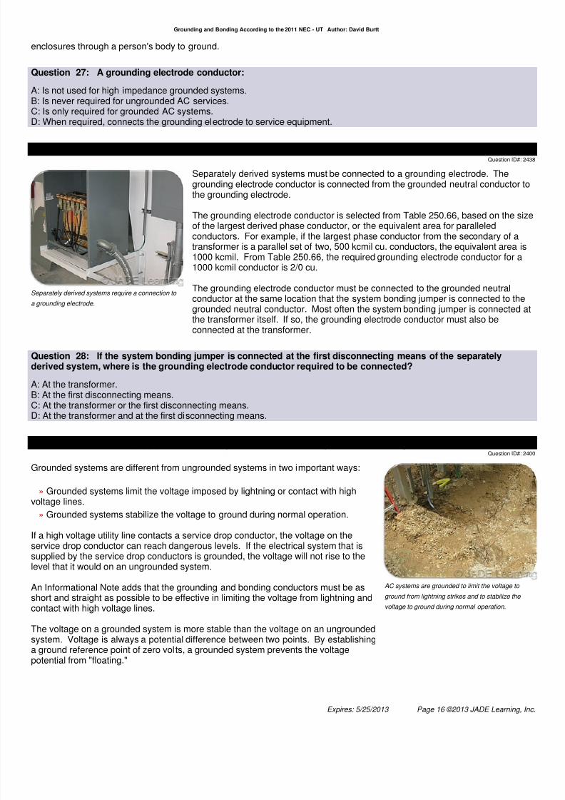
Separately derived systems require a connection to
a grounding electrode.
Separately derived systems must be connected to a grounding electrode. Thegrounding electrode conductor is connected from the grounded neutral conductor tothe grounding electrode.
The grounding electrode conductor is selected from Table 250.66, based on the sizof the largest derived phase conductor, or the equivalent area for paralleledconductors. For example, if the largest phase conductor from the secondary of atransformer is a parallel set of two, 500 kcmil cu. conductors, the equivalent area is1000 kcmil. From Table 250.66, the required grounding electrode conductor for a1000 kcmil conductor is 2/0 cu.
The grounding electrode conductor must be connected to the grounded neutralconductor at the same location that the system bonding jumper is connected to thegrounded neutral conductor. Most often the system bonding jumper is connected athe transformer itself. If so, the grounding electrode conductor must also beconnected at the transformer.
Question 28: If the system bonding jumper is connected at the first disconnecting means of the separatelyderived system, where is the grounding electrode conductor required to be connected? A: At the transformer.B: At the first disconnecting means.C: At the transformer or the first disconnecting means.
D: At the transformer and at the first disconnecting means.
Question 29: 250.4(A)(1) Grounded Systems. Electrical System Grounding.Question ID#: 24
AC systems are grounded to limit the voltage to
ground from lightning strikes and to stabilize the
voltage to ground during normal operation.
Grounded systems are different from ungrounded systems in two important ways:
» Grounded systems limit the voltage imposed by lightning or contact with highvoltage lines.
» Grounded systems stabilize the voltage to ground during normal operation.
If a high voltage utility line contacts a service drop conductor, the voltage on theservice drop conductor can reach dangerous levels. If the electrical system that is
supplied by the service drop conductors is grounded, the voltage will not rise to thelevel that it would on an ungrounded system.
An Informational Note adds that the grounding and bonding conductors must be asshort and straight as possible to be effective in limiting the voltage from lightning andcontact with high voltage lines.
The voltage on a grounded system is more stable than the voltage on an ungroundedsystem. Voltage is always a potential difference between two points. By establishinga ground reference point of zero volts, a grounded system prevents the voltagepotential from "floating."
Expires: 5/25/2013 Page 16 ©2013 JADE Learning, In

7/27/2019 Grounding and Bonding According to the 2011 NEC - UT
http://slidepdf.com/reader/full/grounding-and-bonding-according-to-the-2011-nec-ut 17/32
Grounding and Bonding According to the 2011 NEC - UT Author: David Burtt
Question 29: In a grounded system: A: The voltage will never rise above the applied voltage.B: Grounding and bonding conductors are coiled to better absorb a lightning strike.C: During normal operation the system voltage to earth is stabilized by being grounded.D: The grounding and bonding conductors are isolated from telephone and CATV enclosures.
Question 30: 250.30(A)(3) Grounded Conductor.Question ID#: 24
If the system bonding jumper is installed at the first
disconnect, use Table 250.66 or apply the 12.5%
rule to size the grounded conductor between the
transformer and first disconnect.
If the grounded neutral conductor is connected to the equipment grounding system atthe first disconnecting means, and not at the transformer, the grounded conductorthat is installed between the transformer and first disconnecting means will carry faultcurrent back to the transformer if there is a fault on the secondary of the separatelyderived system. Because the grounded neutral conductor will carry fault current itcannot be smaller than the size of the grounding electrode conductor selected fromTable 250.66.
If the grounded conductor is connected to the equipment grounding system at thetransformer, then the grounded neutral conductor between the transformer and thefirst disconnect will not carry fault current. The grounded neutral conductor only hasto be sized to carry the calculated neutral current, according to Article 220. There isno requirement for the neutral to be at least as large at the grounding electrode
conductor selected from Table 250.66.
When the grounded neutral carries fault current, it must be routed with the phaseconductors and not smaller than the grounding electrode conductor from Table250.66. If the derived phase conductors are larger than 1100 kcmil cu. or 1750 kcmilaluminum, the grounded neutral conductor must be no smaller than 12.5 % of thearea of the phase conductors. If the derived phase conductors are installed inparallel in separate conduits, the grounded neutral conductor is sized based on thelargest phase conductor in each conduit, but not smaller than 1/0 AWG.
Question 30: Which of the following installations of the grounded neutral conductor is a code violation? A: The grounded neutral conductor connected to the equipment grounding system at the first disconnecting means of the
separately derived system.B: The grounded neutral conductor connected to the equipment grounding system at the transformer and sized to carry theunbalanced neutral current.C: A No. 1 AWG cu. grounded neutral conductor installed in two parallel conduits where the largest phase conductor in eacconduit is 4/0 AWG cu.D: A 1/0 AWG cu. grounded neutral conductor installed in two parallel conduits where the largest phase conductor in eachconduit is 2/0 AWG cu.
Expires: 5/25/2013 Page 17 ©2013 JADE Learning, In

7/27/2019 Grounding and Bonding According to the 2011 NEC - UT
http://slidepdf.com/reader/full/grounding-and-bonding-according-to-the-2011-nec-ut 18/32
Grounding and Bonding According to the 2011 NEC - UT Author: David Burtt
Question 31: 250.24 Grounding Service-Supplied Alternating-Current Systems.Question ID#: 24
The grounding electrode conductor is connected
between the load end of the service drop or lateral
up to the service disconnecting means.
One end of the grounding electrode conductor is connected to the groundingelectrode. The other end of the grounding electrode conductor shall be connected tthe grounded conductor at the load end of the service drop or service lateral, in themeter enclosure, or at the service disconnecting means.
The connection between the grounding electrode conductor and the groundedservice conductor must be accessible. A connection between the groundingelectrode conductor and the grounded conductor shall not be made on the load sideof the service disconnecting means.
Question 31: Which of the following is a permitted location to connect the grounding electrode conductor?
A: To an ungrounded conductor in the service equipment.B: To the equipment grounding conductor terminal in a sub-panel.C: To the grounded conductor terminal in a sub-panel.D: To the grounded conductor terminal in the main service disconnecting means.
Question 32: 250.53 Grounding Electrode Installation.Question ID#: 24
Grounding electrodes such as ground rods must be
spaced at least 6 ft. apart.
There are a number of requirements in this section about how to install thegrounding electrode system:
When 2 ground rods or ground plates are installed, they must be at least 6 ft. apartand bonded together.
Bonding jumpers that connect grounding electrodes are bonding jumpers, notgrounding electrode conductors. Grounding electrode conductors must becontinuous. Bonding jumpers used to connect grounding electrodes together arenot required to be continuous.
When metal water pipe is used as a grounding electrode, bonding jumpers must beinstalled around water meters and water filters. An additional grounding electrode inaddition to the metal underground water pipe must be installed to supplement thewater pipe.
If the supplemental electrode is a rod, pipe or plate, the grounding electrodeconductor which connects to it does not have to be larger than No. 6 AWG.
A driven ground rod must be buried at least 8 ft. in the ground. With an 8 ft. groundrod, the connection to the grounding electrode conductor must be made flush withthe ground or below ground. If bedrock is hit when driving the rod, it may be installeat a 45 degree angle. When driving the rod at a 45 degree angle, if bedrock stillprevents the rod from being driven, the ground rod may be buried in a trench whichis at least 30 inches deep.
Question 32: Which of the following statements is true? A: Ground rods must be driven straight into the ground.
Expires: 5/25/2013 Page 18 ©2013 JADE Learning, In

7/27/2019 Grounding and Bonding According to the 2011 NEC - UT
http://slidepdf.com/reader/full/grounding-and-bonding-according-to-the-2011-nec-ut 19/32
Grounding and Bonding According to the 2011 NEC - UT Author: David Burtt
B: Bonding jumpers that connect grounding electrodes are not required to be continuous.C: Ground rods used as electrodes must be at least 8 ft. apart.D: A ground plate used as a supplemental grounding electrode must be connected to the grounding electrode system with minimum No. 4 AWG conductor.
Question 33: 250.68(C)(1) Metallic Water Pipe and Structural Metal.Question ID#: 24
The connection of the grounding electrode to a
continuous metal water pipe must be made within
the first 5 ft. from the point of entrance of the water
pipe.
Metal underground water pipe that is in contact with the earth for at least 10 ft. must
be used as a grounding electrode. Copper, iron or steel water pipe is a groundingelectrode. Metal water pipe used for drinking water, sprinkler systems or industrialprocesses are considered grounding electrodes. The size of the water pipe makesno difference. If it is 3/8 inches or 6 inches, metal water pipe must be used as part ofthe grounding electrode system.
The connection to the metal water pipe must be made within the first 5 ft. of wherethe metal water pipe enters the building. If there are water meters or sections ofinsulating joints, a bonding jumper must be installed to make the pipe electricallycontinuous.
Interior metal pipe is often cut and replaced with plastic pipe. Requiring theconnection of the grounding electrode conductor to the metal pipe within 5 ft. ofwhere the pipe enters the building reduces the risk of losing the grounding electrodeconnection to the grounding electrode.
Except in industrial locations, the metal water pipe inside of buildings which is morethan 5 ft. from the point of entrance cannot be used to interconnect electrodes. Inindustrial locations the pipe must be visible for its entire length if it is used tointerconnect other electrodes.
Question 33: When a buried metallic water pipe is used as part of the grounding electrode system, where is thegrounding electrode conductor required to be connected to the grounding electrode? A: To any accessible point on the metallic water pipe regardless of location.B: To an interior pipe within 5 ft. of where the pipe enters the building.C: On every floor of the building.
D: To an exterior pipe within 5 ft. of where the pipe enters the building.
Grounding and Bonding Basics
Expires: 5/25/2013 Page 19 ©2013 JADE Learning, In

7/27/2019 Grounding and Bonding According to the 2011 NEC - UT
http://slidepdf.com/reader/full/grounding-and-bonding-according-to-the-2011-nec-ut 20/32
Grounding and Bonding According to the 2011 NEC - UT Author: David Burtt
Question 34: 250.4(A)(2) Grounded Systems. Grounding of Electrical Equipment.Question ID#: 24
Enclosures and conduit are grounded to limit the
voltage to ground in case they become energized.
Metal enclosures, raceways, and equipment that contain electrical conductors mustbe connected to earth to limit the voltage to ground.
If the insulation on a conductor fails, the raceway or enclosure can becomeenergized. Grounding equipment enclosures and raceways will limit the voltage risif they become energized under ground- fault conditions.
It is important to note that connecting metal equipment or raceways to ground doesnot by itself provide the necessary safety. Bonding raceways and enclosurestogether, and to the grounded conductor, is what creates an effective ground-faultpath that can de-energize the faulted circuit.
Question 34: Grounding of electrical equipment means: A: Adding an additional grounding electrode at the equipment.B: Connecting equipment, enclosures and raceways to the earth.C: Connecting equipment to the grounded neutral conductor downstream of the service.D: Installing bonding bushings on conduit.
Question 35: 250.35(B) Nonseparately Derived System.Question ID#: 24
If the generator overcurrent device is located in the
disconnecting means, the supply-side bonding
jumper is sized from Table 250.66.
If a generator is installed as a nonseparately derived system, and the generatordoes not have overcurrent protection built into the generator, the supply-sidebonding jumper between the the generator and the disconnecting means is sizedaccording to 250.102(C).
Section 250.102(C) requires the supply-side bonding jumper to be sized from Table250.66, based on the size of the largest derived phase conductor.
For example, if a generator does not have built in overcurrent protection and the
derived phase conductors are 4/0 AWG cu., the supply side bonding jumper cannotbe smaller than No. 2 cu., selected from Table 250.66.
Question 35: What size equipment bonding jumper is required for a nonseparately derived system generatorwhere the derived phase conductors are 3/0 copper and the generator overcurrent device is located in thedisconnecting means? A: No. 4 copper AWG.B: No. 2 copper AWG.C: No. 1 copper AWG.D: 1/0 copper AWG.
Expires: 5/25/2013 Page 20 ©2013 JADE Learning, In
7/27/2019 Grounding and Bonding According to the 2011 NEC - UT
http://slidepdf.com/reader/full/grounding-and-bonding-according-to-the-2011-nec-ut 21/32
Grounding and Bonding According to the 2011 NEC - UT Author: David Burtt
Question 36: 250.94 Bonding for Other Systems.Question ID#: 24
An intersystem bonding termination for grounding
other systems is required.
Telephone, Cable TV, and other limited energy systems must be bonded to theelectrical grounding system at the service. An intersystem bonding termination whichis accessible and external to the service equipment must be provided to make thebonding connections from these systems to the electrical grounding grid. If there areother buildings or structures which are fed from the main building, a grounding meansmust be available there also.
The intersystem bonding termination must have connections for at least 3 intersystembonding conductors. The intersystem bonding device cannot interfere with opening aservice or meter enclosure.
The preferred intersystem bonding method is a device which clamps onto thegrounding electrode conductor and provides the required number of bondingconnections. Other devices, such as bonding bars which connect to the serviceequipment enclosures, are also permitted.
Question 36: Which of the following statements about intersystem bonding is correct? A: Limited energy systems must be isolated from the grounding electrode system.B: A detached garage with electric power and a Cable TV connection does not require an intersystem bonding device.
C: The intersystem bonding device is provided by the telephone company.D: Limited energy systems are bonded to the grounding electrode system at the service.
Question 37: 250.35 Permanently Installed Generators.Question ID#: 24
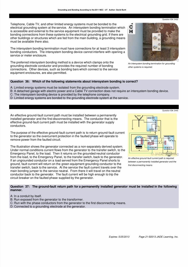
An effective ground-fault current path is required
between a permanently installed generator and the
first disconnecting means.
An effective ground-fault current path must be installed between a permanentlyinstalled generator and the first disconnecting means. The conductor that is theeffective ground-fault current path must be installed with the generator supplyconductors.
The purpose of the effective ground-fault current path is to return ground-fault currentto the generator so the overcurrent protection in the faulted phase will operate to
remove power from the faulted circuit.
The illustration shows the generator connected as a non-separately derived system.Under normal conditions current flows from the generator to the transfer switch, to theEmergency Panel, to the load. Then it returns on the grounded neutral conductorfrom the load, to the Emergency Panel, to the transfer switch, back to the generator.If an ungrounded conductor on a load served from the Emergency Panel shorts toground, fault current will return on the green equipment grounding conductor to thetransfer switch, back to the service. At the service the fault current travels over themain bonding jumper to the service neutral. From there it will travel on the neutralconductor back to the generator. The fault current will be high enough to trip thecircuit breaker on the faulted phase supplied by the generator.
Question 37: The ground-fault return path for a permanently installed generator must be installed in the followingmanner. A: In a conduit by itself.B: Run exposed from the generator to the transformer.C: Run with the phase conductors from the generator to the first disconnecting means.D: Connected to a grounding electrode at the generator.
Expires: 5/25/2013 Page 21 ©2013 JADE Learning, In

7/27/2019 Grounding and Bonding According to the 2011 NEC - UT
http://slidepdf.com/reader/full/grounding-and-bonding-according-to-the-2011-nec-ut 22/32
Grounding and Bonding According to the 2011 NEC - UT Author: David Burtt
Question 38: 250.92(A)&(B) Bonding of Services. Method of Bonding at the Service.Question ID#: 24
Raceways, enclosures, and equipment are bonded
to the grounded conductor.
All of the non-current-carrying metal parts of the service equipment must be bondedtogether. That includes the service raceways, service cable armor, serviceequipment enclosures, gutters, and meter enclosures.
Electrical continuity between the metal parts of the service is accomplished by (1)Bonding service equipment to the grounded neutral conductor; (2) Connectingservice raceways to service equipment enclosures with threaded couplings orthreaded bosses made up wrenchtight; (3) Connecting service raceways andmetal-clad cable to enclosures with threadless couplings and connectors made upwrenchtight; (4) Using bonding-type locknuts and bushings on service raceways.
Bonding jumpers are required on raceways which enter service enclosures throughconcentric or eccentric knockouts on service enclosures. The knockouts punched folarger sized conduit than what is actually used are usually held in place by only asmall strip of metal which is not adequate to bond the conduit to the enclosure.Standard locknuts and bushings shall not be the only means for the bondingrequired by this section but shall be permitted to be installed to make a mechanicalconnection of the raceway(s).
Question 38: Which of the following statements about bonding service raceways is correct? A: EMT can be bonded to service equipment with threadless couplings and locknuts when installed through concentricknockouts.B: At the service, bonding bushings are not necessary if threaded conduit is screwed wrenchtight into a threaded hub.C: Double locknuts can be used to bond service raceways to service enclosures when the raceways are installed throughconcentric knockouts.D: The grounded neutral must be isolated from the metal service equipment.
Question 39: 250.53(A)(2) Ex. Rod, Pipe, and Plate Electrodes. Supplemental Electrode Required.Question ID#: 24
If the resistance to ground for a ground rod is more
than 25 ohms, a second rod must be installed at
least 6 ft. away from the first ground rod.
If a single rod, pipe or plate electrode does not have a resistance to ground of 25ohms, it shall be supplemented by an additional electrode such as the metal frame of
the building, a concrete encased electrode, a ground ring, or a second rod, pipe orplate. All the grounding electrodes must be bonded together. The NEC does notspecify the required resistance to ground of the supplemental electrode; it simplyrequires that a supplemental electrode be installed and bonded to the originalelectrode. The NEC does not require that the two electrodes bonded together have a25-ohms to ground (or lower) resistance.
According to the exception, if a single rod, pipe, or plate grounding electrode has aresistance to earth of 25 ohms or less, the supplemental electrode shall not berequired.
Installing an additional electrode to the rod, pipe or plate electrode will lower the totalresistance to ground of the grounding electrode system.
A low resistance connection to a ground rod or plate is important for the same reasona low resistance is desirable for any grounding electrode. A low resistancegrounding electrode will limit the voltage to ground on raceways and enclosures whenthere is a ground fault, or if the building is struck by lightning.
Question 39: The measured resistance of a single driven ground rod is 60 ohms. What is required? A: Attach an extension to the ground rod and drive it deeper than 8 ft.B: Drive a 2<sup>nd</sup> ground rod and bond it to the first rod.C: Drive additional ground rods until the total resistance is less than 25 ohms.
Expires: 5/25/2013 Page 22 ©2013 JADE Learning, In

7/27/2019 Grounding and Bonding According to the 2011 NEC - UT
http://slidepdf.com/reader/full/grounding-and-bonding-according-to-the-2011-nec-ut 23/32
Grounding and Bonding According to the 2011 NEC - UT Author: David Burtt
D: Increase the size of the grounding electrode conductor.
Question 40: 250.64(D)(1) Service with Multiple Disconnecting Means Enclosures. GroundingElectrode Conductor Taps.
Question ID#: 24
Taps from each service disconnecting means to a
common grounding electrode conductor is another
way to connect a service to the grounding electrode
system.
A third way to connect the grounding electrode conductor to a service that hasmultiple enclosures is to install grounding electrode conductor taps to a commongrounding electrode conductor.
The size of each grounding electrode conductor tap is selected from Table 250.66based on the largest ungrounded service conductor supplying that servicedisconnect.
The common grounding electrode conductor that connects each groundingelectrode conductor tap to the grounding electrode system is also selected fromTable 250.66, but is based on the largest ungrounded service conductor, or theequivalent for paralleled service conductors, supplying the entire service.
Question 40: Three parallel runs of 500 kcmil copper supply a service wireway. Multiple service disconnect
enclosures are mounted on the wireway. A grounding electrode tap conductor is installed from each servicedisconnect to a common grounding electrode conductor. What is the minimum size common grounding electrodeconductor required? A: 1/0 copper.B: 2/0 copper.C: 3/0 copper.D: 4/0 copper.
Question 41: 250.64(D)(3) Service with Multiple Disconnecting Means Enclosures. CommonLocation.
Question ID#: 24
A single grounding electrode conductor can be installed which will ground the entire service. The
size is selected from Table 250.66 based on the size
of the service entrance conductors.
This is the 3rd of 3 ways to make a connection to the grounding electrode when aservice has more than 1 service disconnecting means enclosure.
A single grounding electrode conductor can be installed from the service equipmento a grounding electrode. Each service disconnect enclosure does not require agrounding electrode conductor in this method because the single groundingelectrode conductor is connected at a common service location, such as a servicewireway, and grounds the whole service.
The size of the single grounding electrode is selected from Table 250.66 and isbased on the area of the largest ungrounded service entrance conductor. If theungrounded conductors are installed in parallel, the sum of the equivalent areas ofthe paralleled ungrounded conductors is used. The grounding electrode conductornever is required to be larger than 3/0 cu.
The size of the grounding electrode conductor taps is also selected from Table250.66, but it is based on the size of the service entrance conductors supplying theindividual service disconnect enclosure.
Question 41: If a service is fed with three parallel runs of 500 kcmil copper, what is the minimum size of thegrounding electrode conductor run to the grounded steel frame of a building? A: 3/0 copper.B: 4/0 copper.
Expires: 5/25/2013 Page 23 ©2013 JADE Learning, In

7/27/2019 Grounding and Bonding According to the 2011 NEC - UT
http://slidepdf.com/reader/full/grounding-and-bonding-according-to-the-2011-nec-ut 24/32
Grounding and Bonding According to the 2011 NEC - UT Author: David Burtt
C: 2/0 copper.D: 1/0 copper.
Question 42: 250.52(A)(3) Concrete-Encased Electrode.Question ID#: 24
Concrete-encased electrodes can be horizontal or
vertical and must be at least 20 ft. long.
There are two types of concrete-encased electrodes: (1) steel reinforcing bars or rodswhich are not less than 1/2 inch in diameter and at least 20 ft. long, encased in 2inches of concrete; (2) 20 ft. of bare copper conductor not smaller than No. 4 AWG
encased in 2 inches of concrete.
The steel reinforcing rods must be in a location that is in direct contact with the earth.The reinforcing rods can be connected with tie wires, and a single length of rod canbe used as the concrete-encased electrode. The reinforcing rods cannot be coatedwith non-conductive material.
Section 250.50 requires a concrete-encased electrode to be connected to thegrounding electrode system if it is present. Several states have modified thisrequirement to say a concrete-encased electrode must be used as a groundingelectrode only if it is available. In those jurisdictions, if the footings or foundationshave been poured before the electrical contractor arrives at the site, and a reinforcingrod is not available for use as a grounding electrode, then a grounding connection tothe reinforcing rod is not required.
Question 42: Which of the following is considered a concrete-encased electrode? A: 20 ft. of 3/4 inch steel rebar encased in 2 inches of concrete located within that portion of a concrete foundation or footinthat is in direct contact with the earth.B: 15 ft. of 1/2 inch steel rebar encased in 2 inches of concrete located at the bottom of the foundation in contact with theearth.C: 25 ft. of 1/4 inch steel rebar encased in 2 inches of concrete located at the bottom of the foundation in contact with theearth.D: 20 ft. of 3/4 inch PVC coated steel rebar encased in 2 inches of concrete located at the bottom of the foundation incontact with the earth.
Question 43: Table 250.66 Size of Alternating-Current Grounding Electrode Conductor.Question ID#: 24
The maximum required size for a grounding
electrode conductor to a ground rod is No. 6 AWG.
The maximum required size to a concrete-encased
electrode is No. 4 AWG.
Table 250.66 is used to size the grounding electrode conductor for services andseparately derived systems. It is based on the size of the largest ungroundedservice-entrance conductor or the equivalent area for parallel conductors. Theequivalent area for two, 500 kcmil conductors is 1000 kcmil.
The purpose of the grounding electrode and the grounding electrode conductor is tolimit the voltage to ground if the building is hit by lightning and to provide a groundreference of zero volts for all the electrical conduit and enclosures.
Since the purpose of the grounding electrode conductor is not to carry current, thelargest grounding electrode conductor required by Table 250.66 is 3/0 AWG cu. If the
equivalent size of the service entrance conductor is 1500 kcmil, the groundingelectrode conductor is 3/0 AWG; if the equivalent size of the service-entranceconductors is 2000 kcmil, 2500 kcmil, or 3000 kcmil, the grounding electrodeconductor is still only required to be a 3/0 AWG cu.
Table 250.66 is also used to size 2 other conductor types in addition to the groundingelectrode conductor: the main bonding jumper and the minimum size groundedneutral conductor. However, since both of these conductors are in the path ofreturning fault current, they must be sized to be at least 12.5 % of the largest phaseconductor in sizes larger than 1100 kcmil copper.
Expires: 5/25/2013 Page 24 ©2013 JADE Learning, In

7/27/2019 Grounding and Bonding According to the 2011 NEC - UT
http://slidepdf.com/reader/full/grounding-and-bonding-according-to-the-2011-nec-ut 25/32
Grounding and Bonding According to the 2011 NEC - UT Author: David Burtt
Question 43: What is the minimum size copper grounding electrode conductor for 500 kcmil copper ungroundedservice entrance conductors? A: 3/0 AWG cu.B: 2/0 AWG cu.C: 1/0 AWG cu.D: No. 2 AWG cu.
Question 44: 250.64(D)(1) Service with Multiple Disconnecting Means Enclosures. GroundingElectrode Conductor Taps.
Question ID#: 24
Grounding electrode conductor taps from each
enclosure can be made to a common grounding
electrode conductor.
This is 1 of the 3 ways to make a connection to the grounding electrode when aservice has more than 1 disconnecting means enclosure.
In this method taps from each service disconnect enclosure are connected to acommon grounding electrode conductor that is connected to the grounding electrode.The grounding electrode is usually effectively grounded building steel or a groundedmetal water line.
Table 250.66 is used to size the common grounding electrode conductor, based onthe size of the largest service entrance conductor, or the sum of the area of paralleledconductors, for the entire service. The size of the grounding electrode conductor tapsis also selected from Table 250.66, but it is based on the size of the serviceconductors supplying each service disconnect enclosure.
The tap conductors must be connected to the common grounding electrodeconductor with connectors listed as grounding and bonding equipment, or byexothermic welding. The common grounding electrode cannot be spliced.
Question 44: A service consists of two, 200 amp main service disconnects mounted on a wireway. Eachdisconnect is fed with 3/0 THHW copper conductors. What size grounding electrode conductor tap is required fromeach of the 200 amp service disconnects to the common grounding electrode conductor that is connected to agrounded metal water line? A: No. 6 cu.
B: No. 4 cu.C: No. 2 cu.D: No. 1 cu.
Question 45: 250.35(A) Separately Derived System.Question ID#: 24
If a permanently installed generator is installed as a
separately derived system, the generator is
grounded and bonded just like a transformer.
When a generator is installed as a separately derived system, the grounded neutrais bonded to the frame of the generator. A grounding electrode and groundingelectrode conductor are connected to the generator's grounded neutral conductor.
In the transfer switch the grounded neutral from the generator is switched along witthe phase conductors. The grounded neutral is isolated from the transfer switch
enclosure. A supply-side bonding jumper is installed between the generator andtransfer switch to bond the two pieces of equipment together and provide aneffective fault-current path back to the generator in case of a ground-fault.
Basically, bonding and grounding a generator that is installed as a separatelyderived system is just like bonding and grounding a transformer. When there is aground-fault on a system supplied by a generator installed as a separately derivedsystem, fault current travels on the supply-side bonding jumper back to thegenerator where the system bonding jumper ties the supply-side bonding jumper tothe grounded neutral conductor.
Expires: 5/25/2013 Page 25 ©2013 JADE Learning, In

7/27/2019 Grounding and Bonding According to the 2011 NEC - UT
http://slidepdf.com/reader/full/grounding-and-bonding-according-to-the-2011-nec-ut 26/32
Grounding and Bonding According to the 2011 NEC - UT Author: David Burtt
Question 45: Which of the following statements best describes a permanently installed generator connected as aseparately derived system? A: The grounded neutral from the generator is isolated from the generator frame.B: The grounded neutral from the generator is connected to the grounded neutral of the utility service in the transfer switch.C: The frame of the generator serves as the grounding electrode.D: The grounded neutral is bonded to the generator frame and switched in the transfer switch.
Question 46: 250.50 Grounding Electrode System.Question ID#: 24
All grounding electrodes must be bonded together.
All grounding electrodes present at a building must be bonded together to form agrounding electrode system. Individual grounding electrodes are tied together sothey are no longer separate electrodes, but part of a grounding electrode system. Asystem of grounding electrodes has less resistance than a single electrode andprovides a better ground.
Grounding electrodes include metal water pipe, the metal frame of a building,concrete-encased electrodes (rebar), ground ring, rod, pipe, and plate electrodes,and other local metal underground systems or structures.
Some state electrical boards have modified this section to say grounding electrodesare required to be bonded to other grounding electrodes if they are available, not if
they are present . For these jurisdictions, if a concrete-encased electrode is buriedin the concrete and not available as a grounding electrode, it does not need to beincluded in the grounding electrode system.
Question 46: A grounding electrode system at a building is created by: A: Driving a ground rod.B: Replacing a short piece of plastic water pipe with metal water pipe.C: Bonding all grounding electrodes together.D: Bonding service equipment enclosures together.
Question 47: 250.34(B) Portable and Vehicle-Mounted Generators. Vehicle-Mounted Generators.Question ID#: 24
Vehicle-mounted generators do not require a
connection to a grounding electrode if only
equipment on the generator is supplied.
Vehicle-mounted generators are mounted on the back of a truck or on a trailer. Theare easily moved from one location to another. These generators are used forsupplying power when a portable generator does not have enough capacity to feedthe load.
When a vehicle mounted the generator only supplies equipment located on thevehicle or cord-and-plug connected equipment through receptacles mounted on thevehicle, the generator is not required to be connected to a grounding electrode.
The grounding terminals on the generator receptacles and other normallynon-current carrying metal parts of the equipment on the vehicle must be connectedto the generator frame. The frame of the generator is required to be bonded to the
frame of the vehicle to eliminate any possibility of a voltage difference between thetwo frames. Failure to bond the vehicle frame to the frame of the generator couldresult in a shock hazard under fault conditions.
Vehicle-mounted generators cannot supply fixed wiring systems, such as distributiopanelboards, unless the generator conductors are connected to the load through atransfer switch.
Question 47: A vehicle-mounted generator, which is not a separately derived system, supplies cord-and-plugconnected equipment through receptacles mounted on the vehicle. Which of the following statements is true?
Expires: 5/25/2013 Page 26 ©2013 JADE Learning, In

7/27/2019 Grounding and Bonding According to the 2011 NEC - UT
http://slidepdf.com/reader/full/grounding-and-bonding-according-to-the-2011-nec-ut 27/32
Grounding and Bonding According to the 2011 NEC - UT Author: David Burtt
A: A bonding jumper between the generator frame and the building grounding electrode system must be installed.B: A ground rod is required to be driven and connected to the generator frame.C: The generator grounded neutral conductor must be bonded to the generator frame.D: The frame of the generator is required to be bonded to the vehicle frame.
Question 48: 250.28(D)(3) Separately Derived System with More Than One Enclosure.Question ID#: 24
The system bonding jumper is selected from Table
250.66 based on the size of the largest ungrounded
feeder conductor serving each enclosure.
The system bonding jumper for a separately derived system performs the same
function as the main bonding jumper does for a service. Like the main bonding jumper, the size of the system bonding jumper is selected from Table 250.66.
If the transformer supplies more than a single enclosure, and the system bonding jumpers are installed in each enclosure, then the size of the system bonding jumpeis based on the largest ungrounded conductor serving that enclosure.
If a single system bonding jumper is located at the transformer, the size of thesystem bonding jumper is selected from Table 250.66, based on the size of thederived phase conductors.
Question 48: A transformer supplies three, 200 amp panelboards with 3/0 cu. THHN ungrounded conductors toeach panelboard. A system bonding jumper is connected in each enclosure. What is the minimum size systembonding jumper? A: No. 4 cu.B: No. 2 cu.C: 1/0 cu.D: 2/0 cu.
Question 49: 250.24(A)(2) Grounding Service-Supplied Alternating-Current Systems. OutdoorTransformer.
Question ID#: 24
If the transformer is located outside the building, a
connection to a grounding electrode is required
outside the building.
Except for high-impedance grounded neutral systems, a connection between thegrounding electrode conductor and the grounded conductor is required at eachoutdoor transformer, or at some other location outside the building.
Most outdoor transformers are usually installed, owned and maintained by the servingutility and therefore not covered by the NEC.
There are situations where the utility supplies a power distribution center and fromthat point the power is distributed by the owner to the other buildings on the property.Normally a customer owned transformer is installed at each building on the property.Since the transformers are owned and maintained by the customer, the requirementsof the NEC apply, and a connection between the grounding electrode conductor andthe grounded conductor is required at the transformer or elsewhere outside the
building.
Question 49: A service supplied by an outdoor transformer: A: Must have a connection to a grounding electrode conductor inside the building.B: Does not need a grounding electrode.C: Must have a connection to a grounding electrode conductor outside the building.D: Must have a connection at any accessible location.
Expires: 5/25/2013 Page 27 ©2013 JADE Learning, In

7/27/2019 Grounding and Bonding According to the 2011 NEC - UT
http://slidepdf.com/reader/full/grounding-and-bonding-according-to-the-2011-nec-ut 28/32
Grounding and Bonding According to the 2011 NEC - UT Author: David Burtt
Question 50: 250.64(D)(3) Service with Multiple Disconnecting Means Enclosures. CommonLocation.
Question ID#: 24
The grounding electrode conductor connects the
service equipment to the grounding electrode
system.
When installing multiple service enclosures for service disconnects, one of theapproved methods for installing the grounding electrode conductors is to run from acommon location to the grounding electrode. The size of the grounding electrodeconductor is selected from Table 250.66, based on the largest ungrounded serviceconductor supplying the wireway on the supply side of the service disconnecting
means.
Since the grounding electrode will never see the fault level currents that the mainbonding jumper or the equipment bonding jumper on the supply side of the servicewill see, the grounding electrode conductor never has to be larger than 3/0 copper,no matter how large the service entrance conductors are.
Question 50: A service is supplied by three parallel 500 kcmil ungrounded copper service conductors in threeseparate conduits, what is the minimum size of the grounding electrode conductor run from the wireway to thebuilding steel?
A: 4/0 copper.B: 3/0 copper.C: 2/0 copper.D: 1/0 copper.
Question 51: 250.64 Grounding Electrode Conductor Installation.Question ID#: 24
No. 4 AWG or larger grounding electrodes must be
protected from physical damage.
Grounding electrode conductors must be securely fastened to the building orstructure. A No. 4 AWG or larger grounding electrode conductor must be protectedif it is exposed to physical damage. A No. 6 AWG grounding electrode conductor isnot required to be protected if it is not exposed to physical damage.
» Grounding electrode conductors must be installed in one continuous lengthwithout a splice, unless:The splice is made with an irreversible compression-type connector listed forgrounding and bonding.
» The splice is made by exothermic welding.
» The grounding electrode conductor is made up of busbars which are connectedtogether to form a single conductor.
On new installations there is no reason to splice the grounding electrode conductorThe permission to splice the grounding electrode conductor is most commonly usedon remodeling projects or when electrical equipment is being replaced.
Question 51: A No. 4 AWG cu. grounding electrode conductor is installed without a raceway in an alleyway
subject to truck traffic. Which of the following statements about the grounding electrode conductor is true? A: The grounding electrode conductor must be protected from physical damage.B: The grounding electrode conductor cannot be longer than 8 ft.C: The grounding electrode conductor must be connected to the grounding electrode by exothermic welding.D: The grounding electrode conductor must be encased in concrete.
Expires: 5/25/2013 Page 28 ©2013 JADE Learning, In

7/27/2019 Grounding and Bonding According to the 2011 NEC - UT
http://slidepdf.com/reader/full/grounding-and-bonding-according-to-the-2011-nec-ut 29/32
Grounding and Bonding According to the 2011 NEC - UT Author: David Burtt
Exercises: Grounding and Bonding at the Service.
Question 52: 250.24(A)(5) Grounding Service-Supplied Alternating-Current Systems. Load-SideGrounding Connections.
Question ID#: 24
The grounded conductor cannot be reconnected to
ground on the load side of the service disconnectin
means.
250.24(A)(5): A grounded conductor shall not be connected to normally non-current-carrying metal parts of equipment, to equipment grounding conductor(s),or be reconnected to ground on the load side of the service disconnecting means except as otherwise permitted in this article.
Some electricians think if a little grounding is good, then more grounding is better.According to this section, grounding the neutral at the service is the only place wherethe neutral can be connected to ground. At every location after the servicedisconnecting means, the neutral and equipment grounding conductors must beseparated. The grounded (neutral) conductor cannot be connected to the enclosureon the load side of the service but must be insulated from ground.
Only in existing installations can the grounded conductor be connected to normallynon-current-carrying metal parts of equipment, such as with existing ranges and
clothes dryers.
In new installations an equipment grounding conductor must be included in the circuitto ground equipment and enclosures. The equipment grounding conductor carriesfault current back to the electrical source under ground-fault conditions. Thegrounded conductor carries neutral and unbalanced current. The National ElectricalCode wants to keep these 2 different types of current separate.
Question 52: Which of the following installations is a code violation? A: Connecting the grounded conductor to the equipment grounds at the service.B: Bonding the grounded conductor to the enclosure in a sub-panel.C: Leaving the grounded conductor bonded to the metal frame of an existing range.
D: Using an equipment grounding conductor to ground the frame of a dryer in a new installation.
Question 53: 250.20(B) Alternating-Current Systems to Be Grounded.Question ID#: 24
AC systems of 50 volts to less than 1000 volts must
be grounded.
Alternating-current systems of 50 volts to less than 1000 volts that supply premisesmust be grounded under three conditions.
» If the maximum voltage to ground on the ungrounded conductors is not greaterthan 150 volts. Example: a 120/240 volt service to a single family dwelling.
» If the system is 3-phase, 4-wire, wye connected where the neutral conductor isused as a circuit conductor. Example: a 120/208 3-phase, 4-wire system created ba transformer.
» If the system is 3-phase, 4-wire, delta connected in which the midpoint of onephase winding is where the grounded neutral conductor is connected. Example: a120/240 volt system with a high-leg.
Question 53: Which of the following installations is not required to be grounded? A: A 120/240 volt high-leg system.B: A circuit less than 50 volts supplied by a 125 volt grounded transformer.C: A 120/208 volt 3-phase, 4-wire, wye-connected system.
Expires: 5/25/2013 Page 29 ©2013 JADE Learning, In

7/27/2019 Grounding and Bonding According to the 2011 NEC - UT
http://slidepdf.com/reader/full/grounding-and-bonding-according-to-the-2011-nec-ut 30/32
Grounding and Bonding According to the 2011 NEC - UT Author: David Burtt
D: A multi-wire branch circuit used on a 120/240 volt system.
Question 54: 250.4(A)(3)&(4) Bonding of Electrical Equipment. Bonding of Electrically ConductiveMaterials and Other Equipment.
Question ID#: 24
Electrical equipment, enclosures and conduit are
connected together and to the system grounded conductor to establish an effective ground-fault
current path.
Bonding electrical equipment, enclosures, raceways, and other equipment thatmight become energized to the grounded conductor at the supply sourceestablishes an effective ground-fault current path.
Normally non-current carrying metal raceways and enclosures must be bondedtogether in an unbroken path that leads from the furthest point in the system all theway back to the electrical supply source.
Bonding raceways, enclosures and equipment to form a continuous path is done bymaking up fittings wrench-tight, scraping away any non-conductive material fromconnection points, and installing bonding jumpers, bonding bushings and otherfittings listed for grounding and bonding.
A single loose fitting or connection can break the ground-fault current path andprevent the overcurrent device from taking the faulted circuit off line.
Question 54: Bonding of electrical equipment means: A: Creating a ground-fault current path.B: Isolating electrical enclosures from ground.C: Inspecting electrical connections for overheating.D: Installing insulating fittings on ungrounded terminals.
Question 55: 250.24(C)(1) Routing and Sizing.Question ID#: 24
When installed with ungrounded service conductors
the grounded conductor cannot be smaller than the
grounding electrode conductor selected from Table
250.66.
The grounded conductor brought to service equipment must be routed with thephase conductors and cannot be smaller than the grounding electrode conductor inTable 250.66.
The grounded conductor must be routed with the phase conductors because if theneutral conductor is not physically installed with the phase conductors, the ACimpedance (resistance) of the circuit is higher than if they are installed in the sameconduit or cabled together. Since the neutral must carry fault-current, the lower theresistance the better.
Table 250.66 is for sizing the grounding electrode conductor. It is also used as aminimum size for the grounded conductor. The service neutral can never be smallethan the required grounding electrode conductor.
The size of the neutral conductor must satisfy two conditions:
» It must be large enough to carry the neutral load, as calculated in Article 220.
» It cannot be smaller than the grounding electrode conductor selected from Table250.66.
There is a further requirement for the size of the grounded conductor. For largeservices where the ungrounded service conductors are larger than 1100 kcmil, thegrounded neutral conductor must be at least 12.5 % of the area of the ungroundedconductors. The kcmil area of conductors is given in Chapter 9, Table 8 (Properties
Expires: 5/25/2013 Page 30 ©2013 JADE Learning, In

7/27/2019 Grounding and Bonding According to the 2011 NEC - UT
http://slidepdf.com/reader/full/grounding-and-bonding-according-to-the-2011-nec-ut 31/32
Grounding and Bonding According to the 2011 NEC - UT Author: David Burtt
of Conductors).
For example: three 500 kcmil conductors are installed in parallel. What is the minimum size for the grounded neutralconductor? Answer: The equivalent size service conductor is 1500 kcmil. Convert to mils to make the math easier =1,500,000 mils. 1,500,000 mils x 12.5% (.125) = 187,500 mils. From Table 8, the neutral must be equal to or larger than187,000 mils or size 4/0.
Question 55: What is the minimum size cu. grounded neutral conductor for a service which uses 2/0 cu.ungrounded conductors? A: 4/0 AWG.B: 2/0 AWG.C: No. 4 AWG.D: No. 2 AWG.
Expires: 5/25/2013 Page 31 ©2013 JADE Learning, In

7/27/2019 Grounding and Bonding According to the 2011 NEC - UT
http://slidepdf.com/reader/full/grounding-and-bonding-according-to-the-2011-nec-ut 32/32
Grounding and Bonding According to the 2011 NEC - UT Author: David Burtt