grounding considerations for industrial power systems
TRANSCRIPT
GROUNDING CONSIDERATIONS FOR INDUSTRIAL POWER
SYSTEMS
Matt McBurnett of VI Engineering
2010 Industry Applications Society Annual Meeting - Houston, TXOctober 3-7, 2010

Contact Information
VI Engineering, LLCwww.viservices.comMain: 281-271-8374Facsimile: 281-754-4689
Matt McBurnett, [email protected]: 281-271-8377Mobile: 281-536-5494
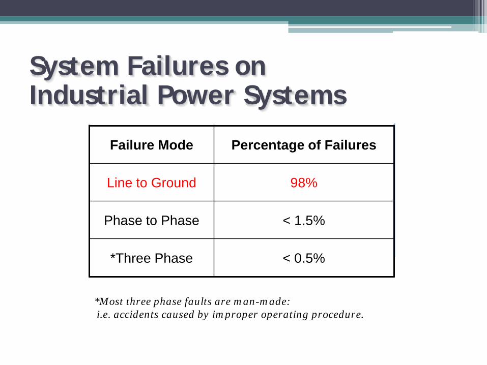
System Failures on Industrial Power Systems
Failure Mode Percentage of Failures
Line to Ground 98%
Phase to Phase < 1.5%
*Three Phase < 0.5%
*Most three phase faults are man-made: i.e. accidents caused by improper operating procedure.
First Half Agenda – System Grounding• What is a ground fault?• What happens in an ungrounded system?• What happens in a solidly grounded system?• Application of resistance grounding• Resistance grounding and generators

What is a Ground Fault?
• Contact between ground and an energized conductor
• Unleashes large amount of electrical energy
• Dangerous toequipment and people
Definitions• System Grounding – An intentional ground on
the system• Resistance Grounding – A type of grounding
using a resistor in the neutral (system or derived) to limit available fault current
• Ground Fault Protection – Detection of an unintentional ground on the system and taking appropriate action

Two Types of FaultsBolted Faults• Solid connection between two
phases or phase and ground resulting in high fault current.
• Stresses are well contained so fault creates less destruction.
Arc Faults• Usually caused by insulation
breakdown, creating an arc between two phases or phase to ground.
• Intense energy is not well contained, and can be very destructive.

600 Volt “THHN” Power Cable
Arcing Fault

Grounding Definition
Neutral grounding means a permanent and continuous conductive path to the earth with sufficient ampacity to carry any fault current liable to be imposed on it, sufficiently low impedance to limit the voltage rise above ground and to facilitate the operation of the protective devices in the circuit.
To Load
Bonding Jumper
Metal Enclosures
Source
Transformer BankSystem Ground Equipment Ground

System Grounding Methods
• Ungrounded• Solidly Grounded• Impedance Grounded
▫ Low Resistance Grounded▫ High Resistance Grounded▫ Reactance Grounded

Ungrounded Systems
• Advantages▫ Negligible fault current on first
ground fault▫ No tripping on first ground fault
• Disadvantages▫ Difficult to locate ground faults▫ 5 to 6 times transient over-
voltage on intermittent, sputtering arcing ground faults
Popular in 3-wire LV systems up to 1950s
BØAØ
CØ
BØAØ
CØ

Industry Recommendations
IEEE Std 242-2001 (Buff Book)Recommended Practice for Protection and Coordination of Industrial and Commercial Power Systems
Ungrounded Systems8.2.5 If this ground fault is intermittent or allowed to continue, the system could be subjected to possible severe over-voltages to ground, which can be as high as six to eight times phase voltage.Such over-voltages can puncture insulation and result in additional ground faults. These over-voltages are caused by repetitive charging of the system capacitance or by resonance between the system capacitance and the inductance of equipment in the system.
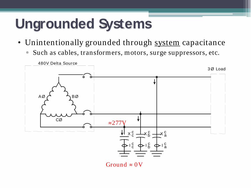
Ungrounded Systems• Unintentionally grounded through system capacitance
▫ Such as cables, transformers, motors, surge suppressors, etc.
I abII c
3Ø Load480V Delta Source
BØ
cc c
caXcX b
ccX
≈277V
AØ
CØ
Ground ≈ 0V

Ground Faults• Ground fault current distribution (minimal current)
CØ
AØ BØ
480V Delta Source3Ø Load
IfcI Ib aIc c c
cXccbX cXa
≈480V
Ground ≈ AØ
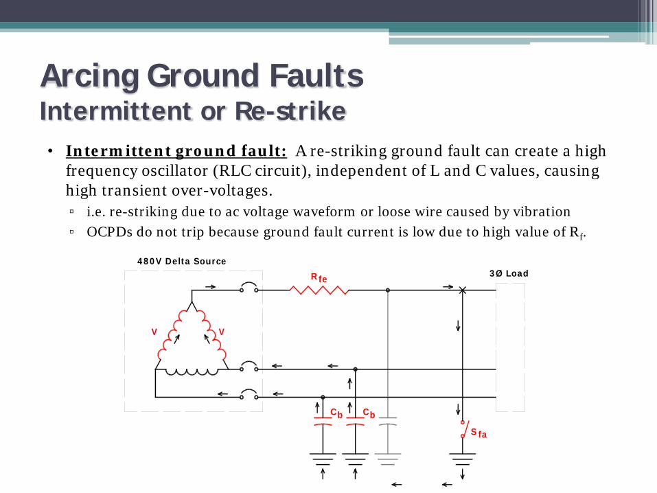
Arcing Ground FaultsIntermittent or Re-strike• Intermittent ground fault: A re-striking ground fault can create a high
frequency oscillator (RLC circuit), independent of L and C values, causing high transient over-voltages.▫ i.e. re-striking due to ac voltage waveform or loose wire caused by vibration▫ OCPDs do not trip because ground fault current is low due to high value of Rf.
V V
480V Delta Source3Ø Load
Cb bC
Rfe
faS
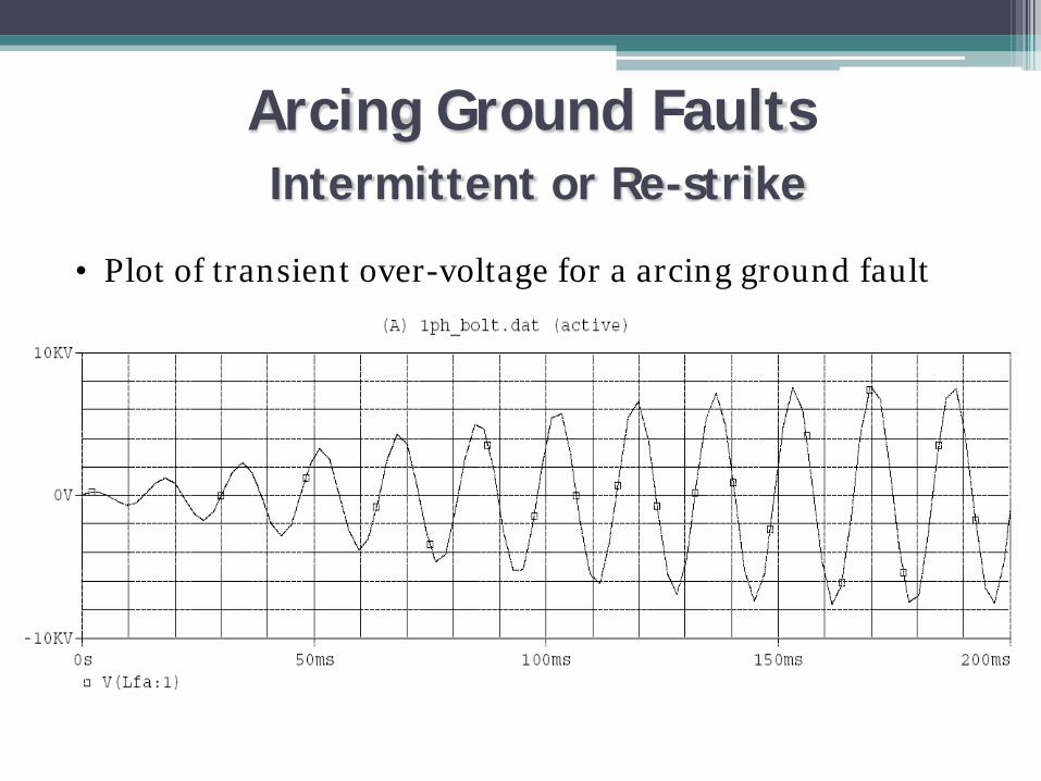
• Plot of transient over-voltage for a arcing ground fault
Arcing Ground FaultsIntermittent or Re-strike

Locating Ground Faults• Good luck!
▫ No direct return to source, only way is through system capacitance.
• Use over-voltage▫ Indicator light and relay method to indicate ground
fault.▫ De-energize one feeder at a time. Very time consuming and dangerous! Unknown ground fault may be on system for long period of time. May de-energize vital equipment trying to find fault.

Solidly Grounded Systems
• Advantages▫ Eliminated transient over-voltage
problem▫ Permit line-to-neutral loads (lighting,
heating cables)▫ Ground faults easy to locate (follow
smoke)
• Disadvantages▫ Cause unscheduled service interruption▫ Danger from low-level arcing ground
faults▫ Strong shock hazard to personnel▫ Coordination Issues▫ Arc-flash issues
CØ
BØAØN
Popular in 4-wire LV systems since 1950s

IEEE – Arcing Faults• IEEE Std 242-2001
Recommended Practice for the Protection and Coordination of Industrial and Commercial Power Systems8.2.2One disadvantage of the solidly grounded 480 V system involves the high magnitude of destructive, arcing ground-fault currents that can occur.
• IEEE Std 141-1993Recommended Practice for Electric Power Distribution for Industrial Plants7.2.4The solidly grounded system has the highest probability of escalating into a phase-to-phase or three-phase arcing fault, particularly for the 480 and 600 V systems. The danger of sustained arcing for phase-to-ground fault…is also high for the 480 and 600 V systems, and low or near zero for the 208 V system. A safety hazard exists for solidly grounded systems from the severe flash, arc burning, and blast hazard from any phase-to-ground fault.
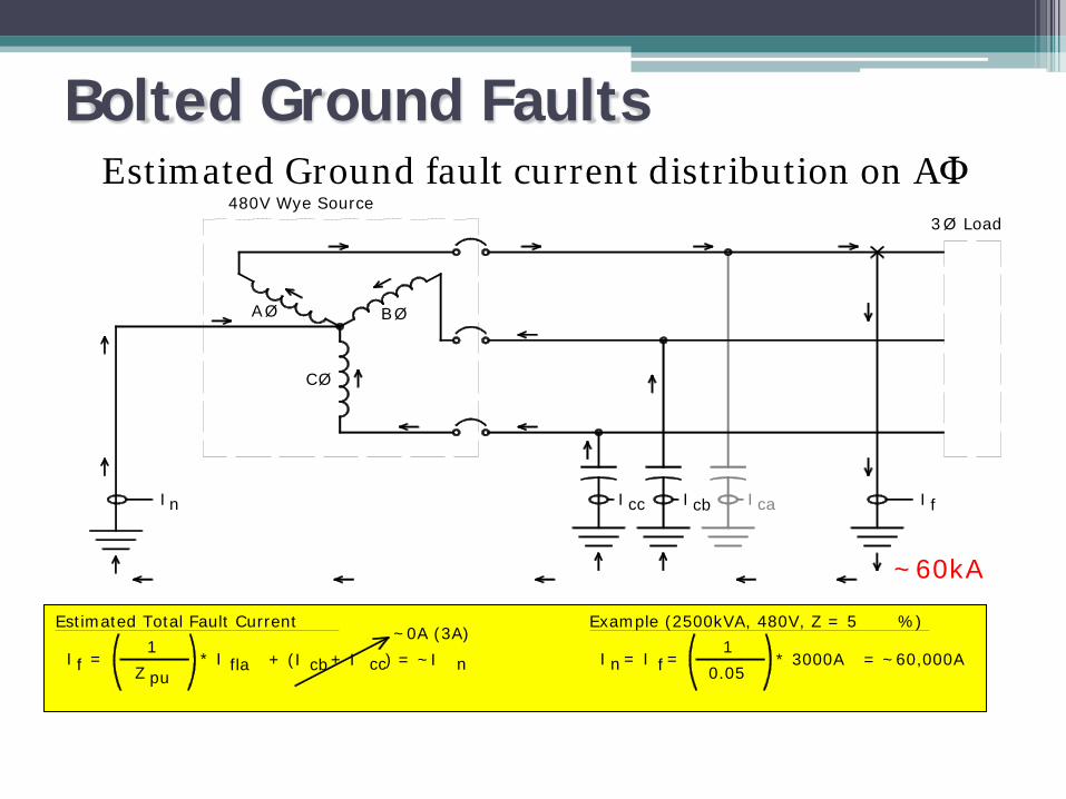
Bolted Ground FaultsEstimated Ground fault current distribution on AΦ
* I flapuZfI =1
Estimated Total Fault Current
480V Wye Source3Ø Load
CØ
BØAØ
I fnI ccI I cb caI
+ (I + I ) = ~Icb cc
~0A (3A)
n = ~60,000A
Example (2500kVA, 480V, Z = 5 %)1
I = I =f 0.05* 3000An
~60kA
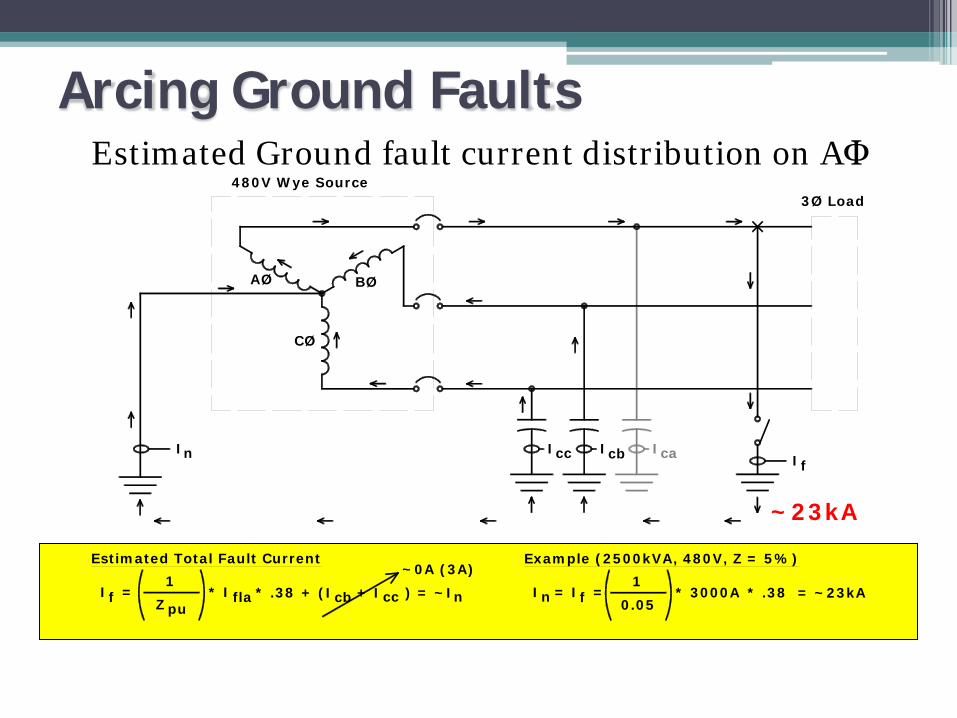
Arcing Ground FaultsEstimated Ground fault current distribution on AΦ
* IflapuZfI =1
Estimated Total Fault Current
480V Wye Source3Ø Load
CØ
BØAØ
IfnI ccI Icb caI
+ (I + I ) = ~Icb cc
~0A (3A)
n = ~23kA
Example (2500kVA, 480V, Z = 5%)1
I = I =f 0.05* 3000An
~23kA
* .38 * .38

Hazards with Ungrounded / Solidly Grounded
• Ungrounded – Method used to ground first power systems▫ Very large transient over-voltage conditions may exist. Insulation not rated, therefore, hazard to personnel and equipment.
▫ Very difficult to locate ground fault. Good chance of second ground fault on a different phase due to
prolonged ground fault.
• Solidly-Grounded – Replaced Ungrounded Systems▫ Very high ground fault currents. Fault must be cleared, shutting down equipment. Generators may not be rated for ground fault
▫ Tremendous amount of arc flash / blast energy. Equipment and people are not rated for energy.

Resistance Grounding
Advantages▫ No transient over-voltages▫ Easy fault location method▫ No Arc Flash Hazards (with ground faults)▫ No coordination issues; ground fault current is consistent▫ May be possible to use higher gauge wires for grounding.
Disadvantages▫ No directly connected line-to-neutral loads▫ Personnel must be trained▫ Requires different arrester ratings▫ Requires higher cable insulation ratings
Popular for 3-wire systems since 1970s
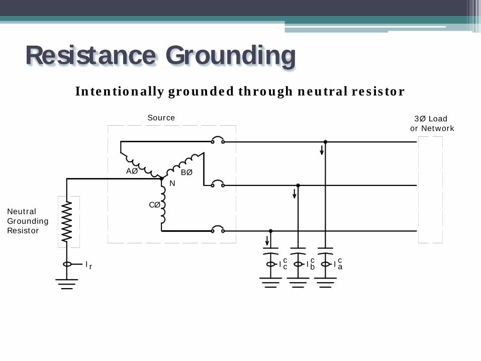
Resistance GroundingIntentionally grounded through neutral resistor
3Ø Load or Network
ccc IabIIcIr
AØ BØ
CØ
Source
N
Neutral Grounding Resistor

Low Resistance Grounding (LRG)• Used on Medium Voltage
▫ Some 5kV systems▫ Mainly 15kV systems
• System charging current may be too high for High Resistance Grounding (HRG)
• Ground Fault▫ Current typically limited to 25 – 400A▫ Typically Trip within 10 - 30 seconds to reduce damage

Duty Ratings for NGR’sIEEE Std 32
Time Rating and Permissible Temperature Rise for Neutral Grounding Resistors
Time Rating (On Time) Temp Rise (deg C)
Ten Seconds (Short Time) 760oC
One Minute (Short Time) 760oC
Ten Minutes (Short Time) 610oC
Extended Time 610oC
Continuous 385oC
Duration Must Be Coordinated With Protective Relay Scheme
Low Resistance Grounding (LRG)
• Application Notes▫ Line-to-neutral voltage for Resistor Line-to-line voltage for Grounding Transformer
▫ Rated current Consider change of resistance due to heat rise Consider harmonics, leakage, etc. Re-striking faults
▫ Vented Enclosure type (NEMA vs. IEC) Resistor must ‘breathe’
▫ CTs and Relays Neutral or Ground side of Resistor

Common options• Enclosure rating• Enclosure finish• Current transformer• Potential transformer• Disconnect switch• Entrance/exit bushings • Elevating stand• Seismic rating• Hazardous area classification• Third party certification
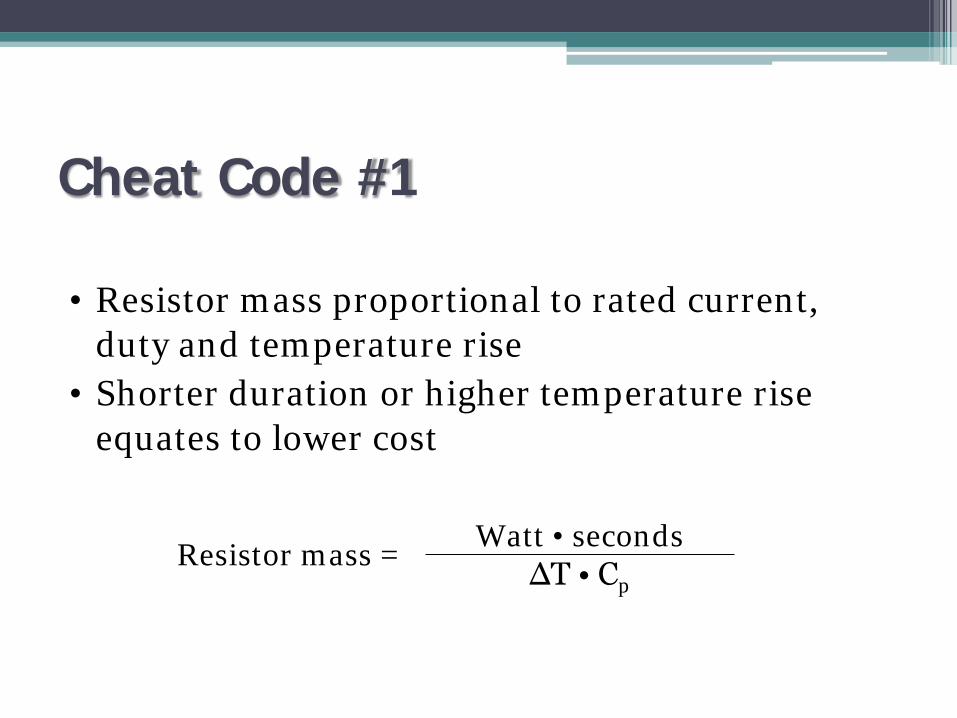
Cheat Code #1
• Resistor mass proportional to rated current, duty and temperature rise
• Shorter duration or higher temperature rise equates to lower cost
Watt • seconds∆T • Cp
Resistor mass =

High Resistance Grounding• How does HRG improve safety and reliability?
▫ Inserts a resistor between neutral and ground▫ Dramatically reduces risk of Electrocution▫ Eliminates approximately 95% of Arc Flash /
Blast InjuriesSource(Wye)
HRG CØ
BØAØ
N
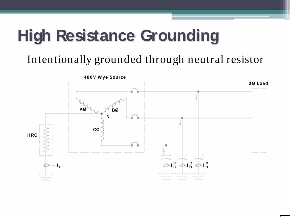
High Resistance GroundingIntentionally grounded through neutral resistor
ccc IabIIcIr
AØ BØ
CØ
3Ø Load480V Wye Source
HRG
N

High Resistance Grounding
• Advantages▫ Eliminates overvoltage transients▫ Allows faulted circuit to continue
operation• Disadvantages
▫ Potential for nuisance alarming▫ Maintenance personnel may ignore first fault
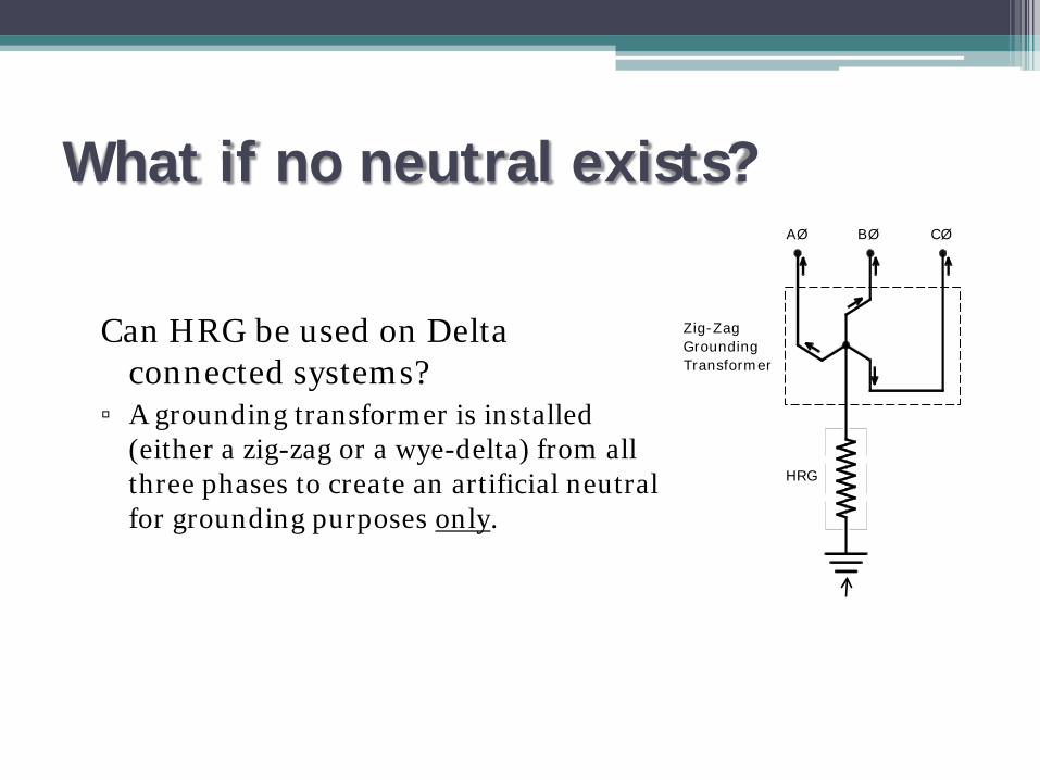
What if no neutral exists?
Can HRG be used on Delta connected systems?
▫ A grounding transformer is installed (either a zig-zag or a wye-delta) from all three phases to create an artificial neutral for grounding purposes only.
HRG
Zig-ZagGroundingTransformer
AØ BØ CØ

System Capacitance
AØ BØ
CØ
N
In a ground fault, which is the path of least resistance?
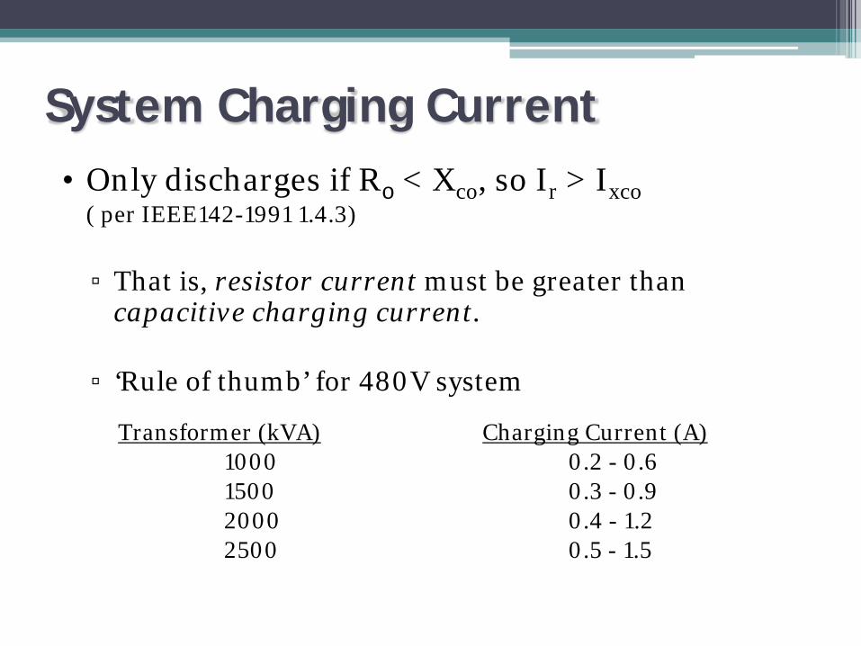
System Charging Current• Only discharges if Ro < Xco, so Ir > Ixco
( per IEEE142-1991 1.4.3)
▫ That is, resistor current must be greater than capacitive charging current.
▫ ‘Rule of thumb’ for 480V system
Transformer (kVA) Charging Current (A)1000 0.2 - 0.61500 0.3 - 0.92000 0.4 - 1.22500 0.5 - 1.5

Estimating Charging Current

Cheat Code #2
• Resistance increases as resistor heats up• Cheaper stainless steel alloys may produce
undesirable results
Resistance change per degree C
Nickel chromium 0.01%
18SR/1JR SS 0.02 - 0.04%
304SS 0.22%

Fault Location
HRG
480V Wye Source
C Ø
B ØA Ø
55.4 ohms
• Operator controlled contactor connected across half the grounding resistor
• When activated, contactor alternately shorts half the resistor and forces the current to double
•Possible to use ammeter to track the current fluctuation

Ground Fault Location Method
NOTE: Tracking a ground fault can only be done on an energized system. Due to the inherent risk of electrocution this should only be performed
by trained and competent personnel. Appropriate PPE measures should be taken into consideration as well.

Fault Location• Method to quickly locate ground faults.
ZSCT
Meter
ZSCT
MeterMeter
ZSCT
0A
55A
50A
50A80A
80A
50A 50A 50A
50A50A55A30A 30A 30A
30A30A30A
MotorMotor
5A
5A0A
5A
HRG
5A
480V Wye Source 85A
CØ
BØAØ
55.4ohms
Meter reading will alternate from 5A to 10A every 2
seconds.
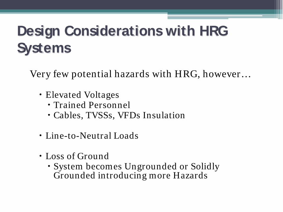
Design Considerations with HRG Systems
Very few potential hazards with HRG, however…
Elevated Voltages Trained Personnel Cables, TVSSs, VFDs Insulation
Line-to-Neutral Loads
Loss of Ground System becomes Ungrounded or Solidly
Grounded introducing more Hazards

Maintenance must be aware of elevated voltages and method to locate fault. IF NOT, DO NOT HAVE TO MAINTAIN POWER. Allowed to trip (same as S-G) but without the hazards.
Elevated Voltage HazardProperly rated equipment prevents Hazards.
AØ BØ
CØ
3Ø Load
HRG
480V Wye Source
N
0V
277V
Ground ≈ AØ
0V
480V
480V

Elevated Voltage Hazard• Properly rated equipment prevents Hazards.
AØ BØ
CØ
3Ø Load
HRG
480V Wye Source
N
0V
277V
Ground ≈ AØ
Cables, TVSSs, VFDs, etc. and other equipment must be rated for elevated voltages (Ungrounded Systems).
0V
480V
480V

No Single Phase LoadsNo line-to-neutral loads allowed, prevents Hazards.
AØ BØ
CØ
3Ø Load
HRG
480V Wye Source
N
0V
277V
Ground ≈ AØ
Line-to-neutral Voltage is backfed via neutral wire, thus, not allowed.
0V
480V
480V277V
X
Phase and Neutral wires in same conduit. If faulted, bypass HRG, thus, Φ-G fault.

Resolve NEC requirement
Add small 1:1 transformer and solidly ground secondary for 1Φ loads (i.e. lighting).
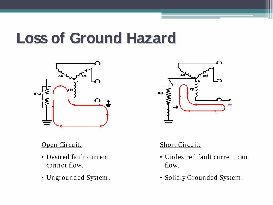
Open Circuit:
• Desired fault current cannot flow.
• Ungrounded System.
Short Circuit:
• Undesired fault current can flow.
• Solidly Grounded System.
Loss of Ground Hazard

Resolving Hazard
• Ground Fault Relay & Sensing Resistor▫ Detects Open / Short
Circuits
AØ BØ
CØHRG
N
SensingResistor
Relay
• Undercurrent and undervoltage relay– Relies on inherent system
imbalances– Detects Open/Short
Circuits

Per IEEE…IEEE Std 142-1991 (Green Book)
Recommended Practice for Grounding of Industrial and Commercial Power Systems
1.4.3The reasons for limiting the current by resistance grounding may be one or more of the following.
1) To reduce burning and melting effects in faulted electric equipment, such as switchgear, transformers, cables, and rotating machines.
2) To reduce mechanical stresses in circuits and apparatus carrying fault currents.
3) To reduce electric-shock hazards to personnel caused by stray ground-fault currents in the ground return path.
4) To reduce the arc blast or flash hazard to personnelwho may have accidentally caused or who happen to be in close proximity to the ground fault.
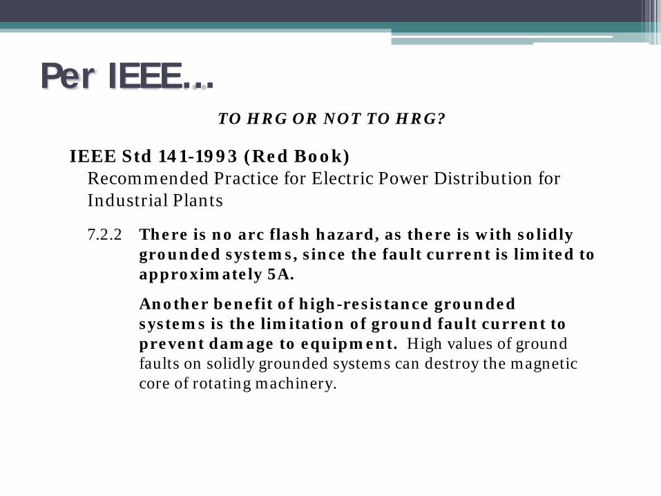
Per IEEE…TO HRG OR NOT TO HRG?
IEEE Std 141-1993 (Red Book)Recommended Practice for Electric Power Distribution for Industrial Plants
7.2.2 There is no arc flash hazard, as there is with solidly grounded systems, since the fault current is limited to approximately 5A.
Another benefit of high-resistance grounded systems is the limitation of ground fault current to prevent damage to equipment. High values of ground faults on solidly grounded systems can destroy the magnetic core of rotating machinery.

Objective
• Minimize the damage for internal ground faults• Limit mechanical stress in the generator from external ground
faults• Provide a means of system ground fault detection• Coordinate with other system/equipment requirements
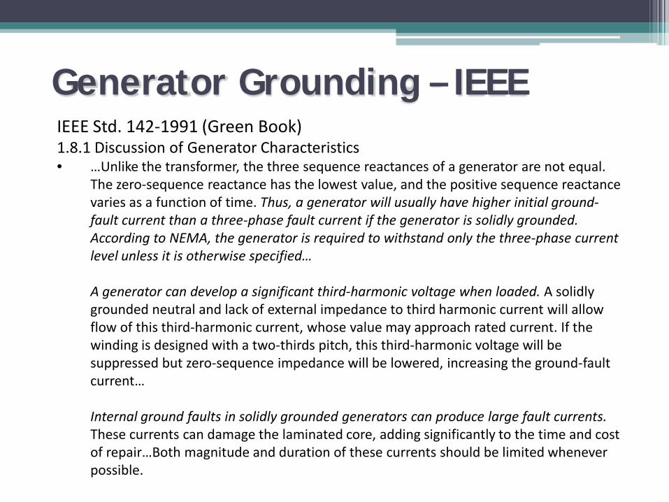
Generator Grounding – IEEEIEEE Std. 142-1991 (Green Book) 1.8.1 Discussion of Generator Characteristics• …Unlike the transformer, the three sequence reactances of a generator are not equal.
The zero-sequence reactance has the lowest value, and the positive sequence reactance varies as a function of time. Thus, a generator will usually have higher initial ground-fault current than a three-phase fault current if the generator is solidly grounded. According to NEMA, the generator is required to withstand only the three-phase current level unless it is otherwise specified…
A generator can develop a significant third-harmonic voltage when loaded. A solidly grounded neutral and lack of external impedance to third harmonic current will allow flow of this third-harmonic current, whose value may approach rated current. If the winding is designed with a two-thirds pitch, this third-harmonic voltage will be suppressed but zero-sequence impedance will be lowered, increasing the ground-fault current…
Internal ground faults in solidly grounded generators can produce large fault currents.These currents can damage the laminated core, adding significantly to the time and cost of repair…Both magnitude and duration of these currents should be limited whenever possible.
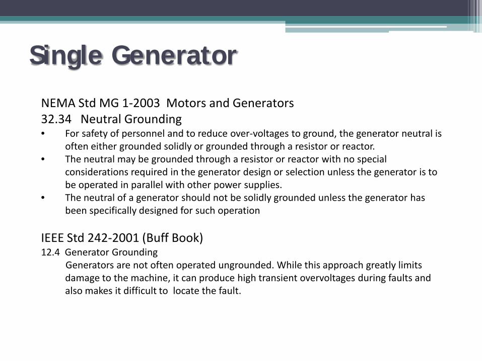
Single Generator
NEMA Std MG 1-2003 Motors and Generators32.34 Neutral Grounding• For safety of personnel and to reduce over-voltages to ground, the generator neutral is
often either grounded solidly or grounded through a resistor or reactor. • The neutral may be grounded through a resistor or reactor with no special
considerations required in the generator design or selection unless the generator is to be operated in parallel with other power supplies.
• The neutral of a generator should not be solidly grounded unless the generator has been specifically designed for such operation
IEEE Std 242-2001 (Buff Book)12.4 Generator Grounding
Generators are not often operated ungrounded. While this approach greatly limits damage to the machine, it can produce high transient overvoltages during faults and also makes it difficult to locate the fault.
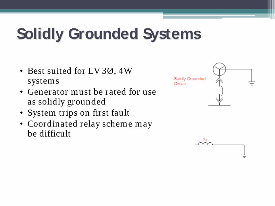
Solidly Grounded Systems
• Best suited for LV 3Ø, 4W systems
• Generator must be rated for use as solidly grounded
• System trips on first fault• Coordinated relay scheme may
be difficult

Resistance Grounding
• Best suited for 3Ø, 3W systems• Capacitive charging current
important• Higher resistance limits damage
on internal fault

Hybrid Grounding
• Low resistance grounding overcomes capacitive charging current
• After generator is isolated the LRG is removed, limiting fault current to 5 A

Paralleled Generators
• Easy if all generators are same design and pitch, always operated at equal loading and are not switched with three pole transfer switch
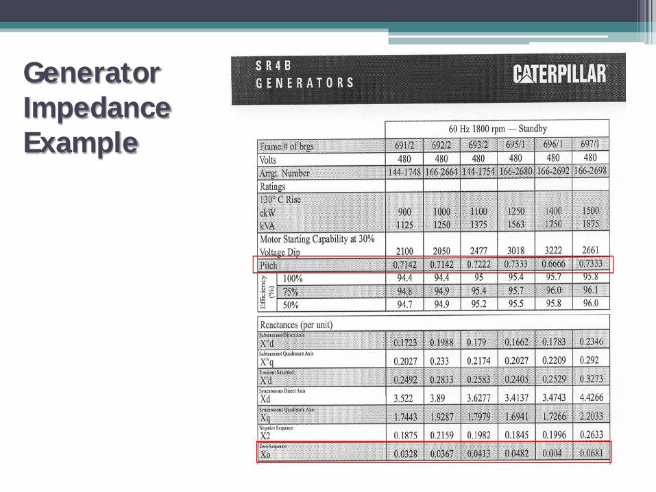
Generator Impedance Example

Separate Grounding Resistors
• Separately grounding prevents circulating 3rd harmonic current• Must have means of disconnecting neutral if generator is being
serviced• Multiple NGR’s has cumulative effect on ground fault current
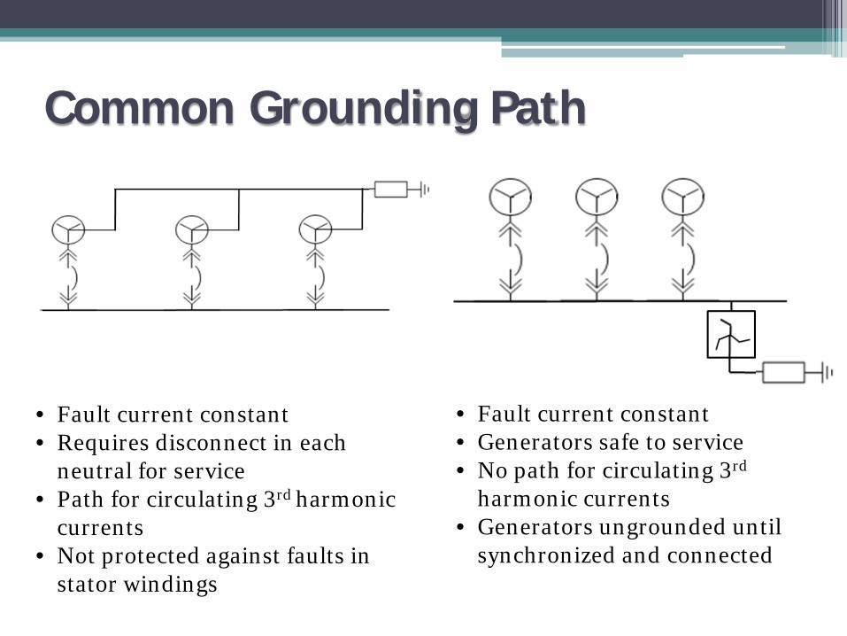
Common Grounding Path
• Fault current constant• Generators safe to service• No path for circulating 3rd
harmonic currents• Generators ungrounded until
synchronized and connected
• Fault current constant• Requires disconnect in each
neutral for service• Path for circulating 3rd harmonic
currents• Not protected against faults in
stator windings

Hybrid Grounding
A neutral deriving transformer holds the fault current on the main bus to a consistent 400 amps. Each generator is protected by
HRG.

Recommendation
• Solidly ground only at LV when generator permits, loads are non-critical and primarily single phase
• HRG at LV • LRG combined with HRG at MV or where
charging current is excessive

Benefits of Grounding
Ungrounded System
Solidly Grounded System
Low Resistance Grounded System
High Resistance Grounded System
Overvoltages Severe None Limited LimitedOvercurrent - Damage at point of fault Unknown Severe Minimal NoneMaintenance Costs High Reasonable Reasonable LowContinuous Operation with Ground Fault
Possible but not recommended Not possible Not possible Ideal
Relay Co-ordination (Appropriate Equipment Tripped, Ease of fault location) Difficult Difficult Good Excellent
Personnel Safety to Personnel Poor Good Good Excellent
Equipment Damage
Downtime
Productivity Impact
System Type

Second Half Agenda
• Equipment Grounding▫ Ground Systems and GEC▫ Bonding▫ Component Grounding▫ Ground Fault Protection
• Substation▫ Criteria for Ground Grid Design▫ Designing Safe and Effective Ground Systems Soil System Conductors Arrangement
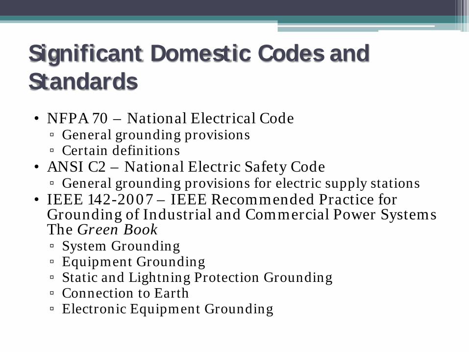
Significant Domestic Codes and Standards• NFPA 70 – National Electrical Code
▫ General grounding provisions▫ Certain definitions
• ANSI C2 – National Electric Safety Code▫ General grounding provisions for electric supply stations
• IEEE 142-2007 – IEEE Recommended Practice for Grounding of Industrial and Commercial Power Systems The Green Book▫ System Grounding▫ Equipment Grounding▫ Static and Lightning Protection Grounding▫ Connection to Earth▫ Electronic Equipment Grounding
Equipment Grounding
• System Grounding – Part 1▫ Includes Grounded Conductor
• Equipment Grounding – Part 2▫ Includes GEC and bonding/grounding of system
components▫ GEC required for HRG, LRG and solidly grounded
systems

Objectives of Equipment Grounding
• To reduced shock hazard to personnel
• To provide adequate current carrying capability (impedance and duration) to handle ground fault current w/o fire or hazard
• To provide a low-impedance return path for ground fault current to ensure operation of overcurrent device

Equipment Grounding Requirements
• Conductive Materials enclosing conductors or equipment (e.g. conduit, motor frames) shall be connected to earth to limit voltage to ground on these items. These shall be:▫ Connected together (bonded)▫ Connected to the grounded conductor
• For LRG or HRG or ungrounded systems, these items must still be bonded together
• Earth cannot be sole EGC or fault current path

Grounding Electrode Conductor (GEC)
• Defined in NEC as “The conductive path installed to connect normally non-current-carrying metal parts of equipment together and to the system grounded conductor or the grounding electrode conductor, or both.”
• Characteristics:▫ Copper or corrosion resistant material▫ Accessible (generally)▫ Sized per NEC Table 250.66
System Bonding Jumper• Defined in NEC as “The connection between the
grounded circuit conductor and the equipment grounding conductor at a separately derived system.”
• Differs from main bonding jumper because main jumper is specific to service
• Characteristics:▫ Copper or corrosion resistant material▫ Accessible (generally)▫ Unspliced▫ Wire, bus or screw▫ Sized per NEC 250.28D, based on phase conductor size -
See Table 250.66

GEC and Bonding Jumper
Grounding Electrode System
• All of the following present at a building or structure served shall be bonded together:▫ Metal Underground Water Pipe▫ Metal Frame of the Building or Structure▫ Concrete Encased Electrode▫ Ground Ring▫ Rod and Pipe Electrodes▫ Other Listed Electrodes▫ Plate Electrodes
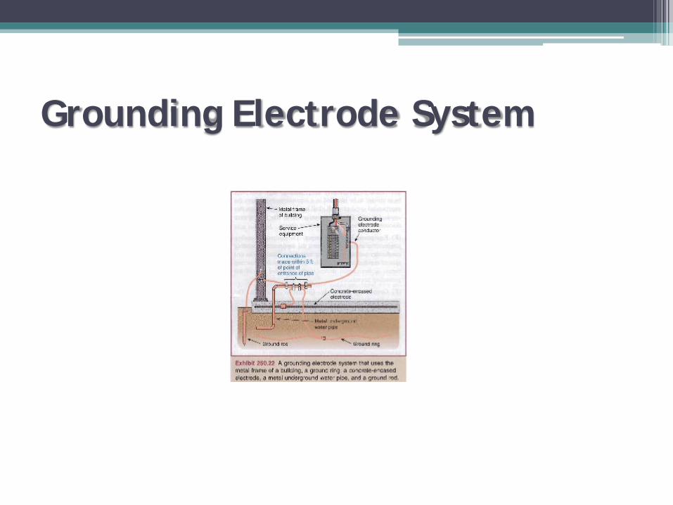
Grounding Electrode System

Bonding
• Bonded, per NEC: Connected to establish electrical continuity and conductivity
• NEC gives bonding requirements▫ Metal raceways, trays, cable armor, enclosures, etc. and
other non-current carrying metal parts shall be bonded
• NEC gives acceptable bonding means▫ Threaded couplings or bosses▫ Threadless couplings where made up tight for raceways▫ Other listed devices such as bonding locknuts, bushings or
bushings with jumpers
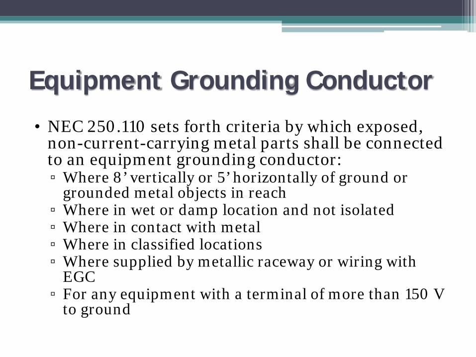
Equipment Grounding Conductor
• NEC 250.110 sets forth criteria by which exposed, non-current-carrying metal parts shall be connected to an equipment grounding conductor:▫ Where 8’ vertically or 5’ horizontally of ground or
grounded metal objects in reach▫ Where in wet or damp location and not isolated▫ Where in contact with metal▫ Where in classified locations▫ Where supplied by metallic raceway or wiring with
EGC▫ For any equipment with a terminal of more than 150 V
to ground

Equipment Grounding Conductor
• Types of EGC are given in NEC article 250.118▫ Copper or Al wire▫ RMC▫ IMC▫ EMT▫ Listed Flex (with conditions)▫ Listed Liquidtight Flex (with conditions)▫ Type AC cable▫ Mineral Insulated Cable▫ Type MC cable▫ Cable tray (with conditions)▫ Cablebus framework (with conditions)▫ Other raceways (e.g. listed gutters)

EGC Identification• EGC can be bare, covered or insulated
▫ Insulation must be green or green with one or more yellow stripes
▫ Green or green with yellow stripes are not permitted to be used for ungrounded or grounded conductors
• Conductor #6 or larger, or conductors in multi-conductor cable can be reidentified by:▫ Stripping insulation▫ Coloring exposed portions green▫ Marking exposed insulation with green tape or
adhesive labels

Size of EGC
• Refer to NEC table 250.122▫ Size based on overcurrent protection▫ Never must be larger than circuit conductor▫ Where a single EGC is run with multiple circuits in
same raceway, cable or tray, it shall be sized based on the largest OC device
▫ For parallel cables, EGC must be run with both sets, with each sized per 250.122

Methods of Equipment Grounding• For grounded systems, the connection shall be made by
bonding the EGC to the grounded service conductor and the GEC
• For fixed equipment connected with permanent wiring, EGC shall be routed with circuit conductors

Unit Substations
• Much more simple than outdoor, open-frame substations (lots more on that later)▫ Voltage gradients are typically not a significant
problem▫ Generally dealing with a metal-enclosed package,
all bonded together▫ All grounding circuits to and from unit substation
must be properly connected▫ Use of impedance grounding greatly reduces risk
to personnel

Unit Substations with Transformers
• Unique problems because two systems are present▫ Must have EGC running back to line-side source▫ Secondary is separately-derived system and is
subject to all rules (recall system grounding, GEC, system bonding jumper, etc.)
• Line-side and load side systems are interconnected due to EGC requirements but are functionally separate

Utilization Equipment

Ground Fault Protection
• Use of phase overcurrent devices is not ideal▫ Can produce less current than device rating thus
trip times can be extremely long (e.g. fuse) with LRG system
▫ Ground faults often are arcing and are intermittent in nature not allowing thermal elements to operate quickly
• Separate ground fault protection is recommended
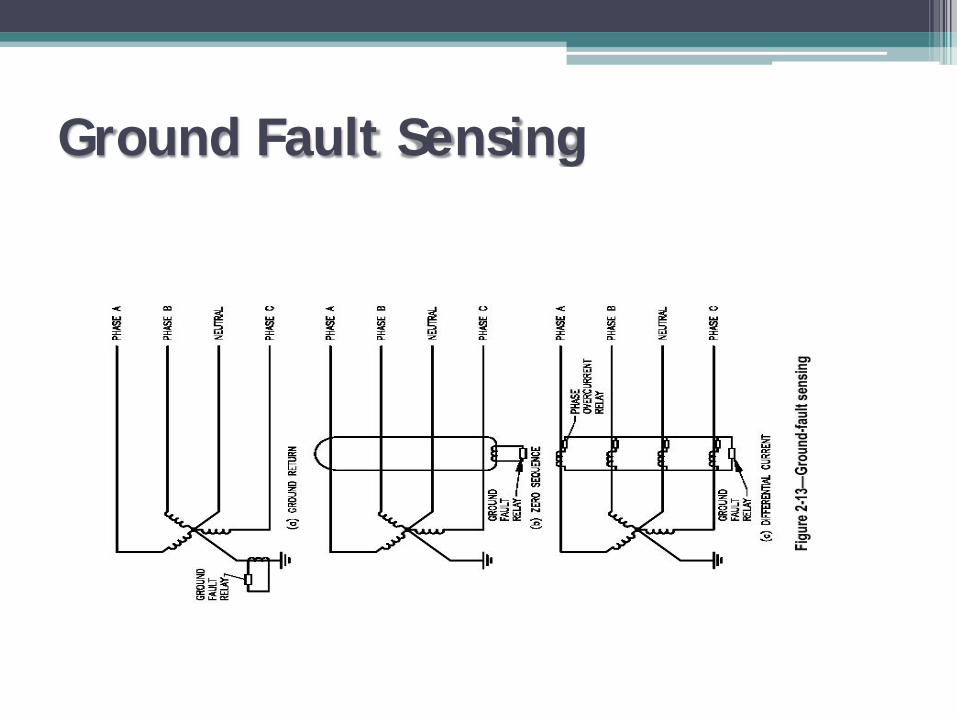
Ground Fault Sensing
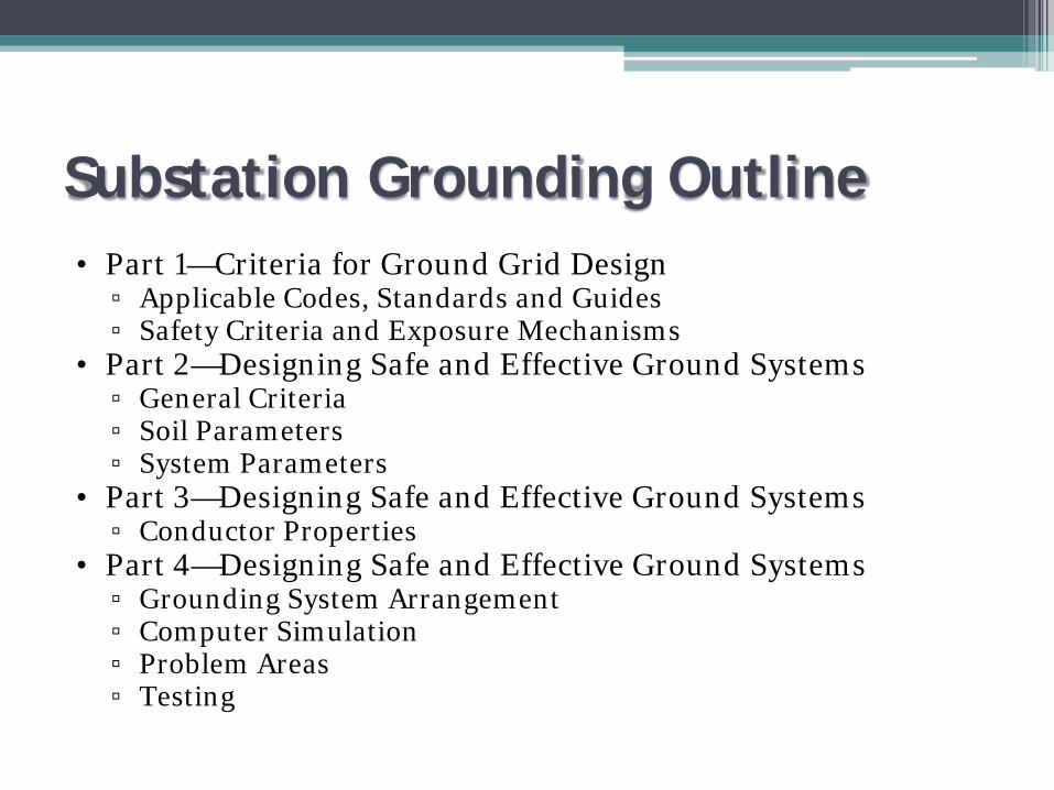
Substation Grounding Outline• Part 1—Criteria for Ground Grid Design
▫ Applicable Codes, Standards and Guides▫ Safety Criteria and Exposure Mechanisms
• Part 2—Designing Safe and Effective Ground Systems▫ General Criteria▫ Soil Parameters▫ System Parameters
• Part 3—Designing Safe and Effective Ground Systems▫ Conductor Properties
• Part 4—Designing Safe and Effective Ground Systems▫ Grounding System Arrangement▫ Computer Simulation▫ Problem Areas▫ Testing
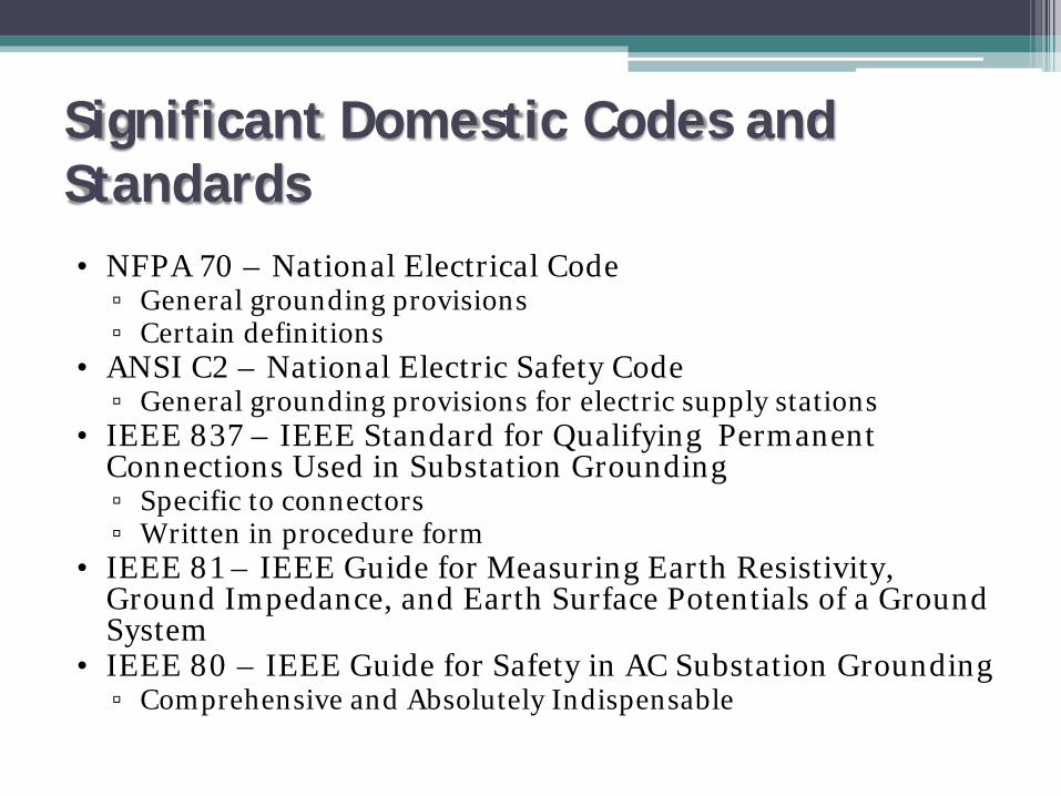
Significant Domestic Codes and Standards• NFPA 70 – National Electrical Code
▫ General grounding provisions▫ Certain definitions
• ANSI C2 – National Electric Safety Code▫ General grounding provisions for electric supply stations
• IEEE 837 – IEEE Standard for Qualifying Permanent Connections Used in Substation Grounding▫ Specific to connectors▫ Written in procedure form
• IEEE 81 – IEEE Guide for Measuring Earth Resistivity, Ground Impedance, and Earth Surface Potentials of a Ground System
• IEEE 80 – IEEE Guide for Safety in AC Substation Grounding▫ Comprehensive and Absolutely Indispensable

Hazardous Conditions
• Shock▫ Not necessarily caused by contact with an intentionally energized
object (that’s what insulation is for)▫ Caused by potential gradients▫ Requires the following simultaneous conditions Current, typically high in relation to the grounding area and
resistance Current distribution through soil resistance causing gradients at
earth’s surface Absence of insulating material that could mitigate current flow
through the body Duration of contact and fault sufficient to develop harmful current
flow through the body Bad luck - Presence of human at wrong place at the wrong time,
bridging two points of potential difference caused by the above items

Current Return Paths
Figure (a): IF = IG Figure (b): IF = IG + ITotal fault current returns through ground Fault current splits

Specific Susceptibility• Physiological Effects of Electric Current
▫ As current increases, the following effects occur 1 mA: threshold of perception 1 to 6 mA: let-go current – unpleasant but can be
released 9 – 25 mA: pain and hard to release; may require
secondary treatment 60 – 100 mA: highly dangerous; ventricle fibrillation,
stoppage of cardio-pulmonary system; immediate treatment required
• Fibrillation Current is the Criterion on Which Analysis is Based
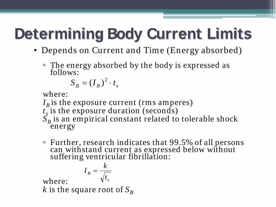
Determining Body Current Limits• Depends on Current and Time (Energy absorbed)
▫ The energy absorbed by the body is expressed as follows:
where:IB is the exposure current (rms amperes)ts is the exposure duration (seconds)SB is an empirical constant related to tolerable shock
energy
▫ Further, research indicates that 99.5% of all persons can withstand current as expressed below without suffering ventricular fibrillation:
where:k is the square root of SB
sBB tIS ⋅= 2)(
sB t
kI =

Current vs. Time• Alternate Analysis
▫ Biegelmier’s Curve
• Summary▫ Eat, drink, survive
shocks better
Don’t Try to Resist It
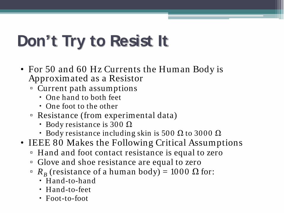
• For 50 and 60 Hz Currents the Human Body is Approximated as a Resistor▫ Current path assumptions One hand to both feet One foot to the other
▫ Resistance (from experimental data) Body resistance is 300 Ω Body resistance including skin is 500 Ω to 3000 Ω
• IEEE 80 Makes the Following Critical Assumptions▫ Hand and foot contact resistance is equal to zero▫ Glove and shoe resistance are equal to zero▫ RB (resistance of a human body) = 1000 Ω for: Hand-to-hand Hand-to-feet Foot-to-foot
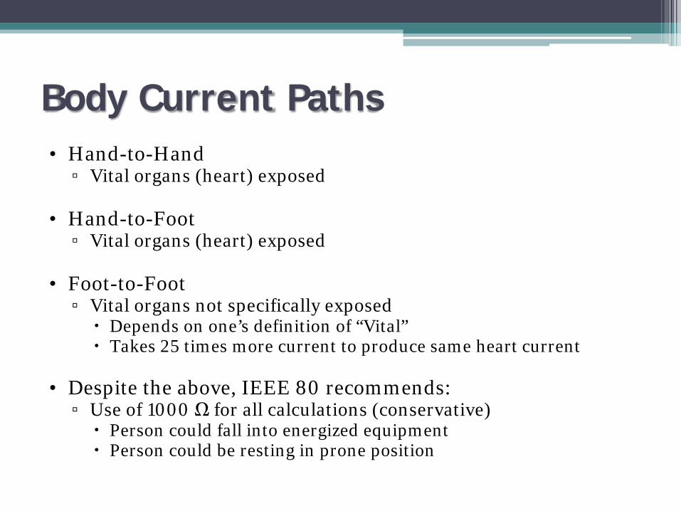
Body Current Paths• Hand-to-Hand
▫ Vital organs (heart) exposed
• Hand-to-Foot▫ Vital organs (heart) exposed
• Foot-to-Foot▫ Vital organs not specifically exposed Depends on one’s definition of “Vital” Takes 25 times more current to produce same heart current
• Despite the above, IEEE 80 recommends:▫ Use of 1000 Ω for all calculations (conservative) Person could fall into energized equipment Person could be resting in prone position

Developing Voltage Criteria
Bth
thb RZ
VI
+=
▫ For the next few slides: RA is the total effective resistance of the accidental circuit in Ω VA is the total effective voltage (step or touch) of the accidental circuit IB is tolerable body current from previous U, Z and If are system parameters Terminal H is a point in system at same potential as grid RB is resistance of body Ib is the body current in A, flows from H to F through the unfortunate individual
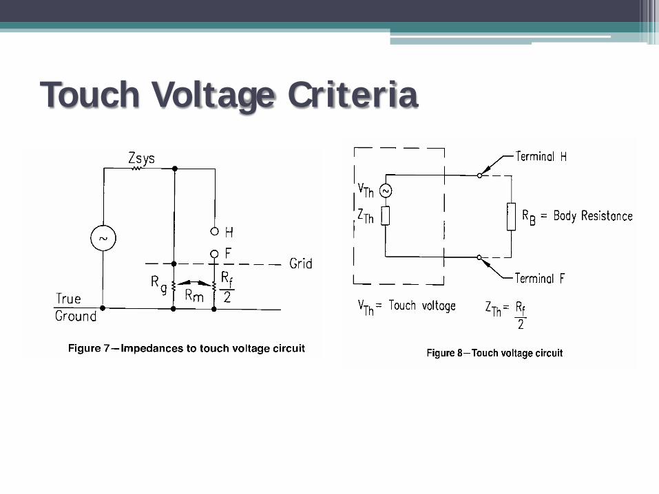
Touch Voltage Criteria

Step Voltage Criteria

Putting it All Together• The maximum driving voltages of
the accidental step circuits are:
For a 50 kg body weight –
For a 70 kg body weight –
Estep is the step voltage in VEtouch is the touch voltage in VCs is the surface layer derating factorRs is the resistivity of the surface in Ω-mts is the duration of the shock in seconds
BfBstep IRRE )2( +=
sssstep t
CE 116.0)61000(50 ρ⋅+=
sssstep t
CE 157.0)61000(70 ρ⋅+=
The maximum driving voltages of the accidental touch circuits are:
For a 50 kg body weight –
For a 70 kg body weight –
Bf
Btouch IR
RE )2
( +=
ssstouch t
CE 116.0)5.11000(50 ρ⋅+=
ssstouch t
CE 157.0)5.11000(70 ρ⋅+=
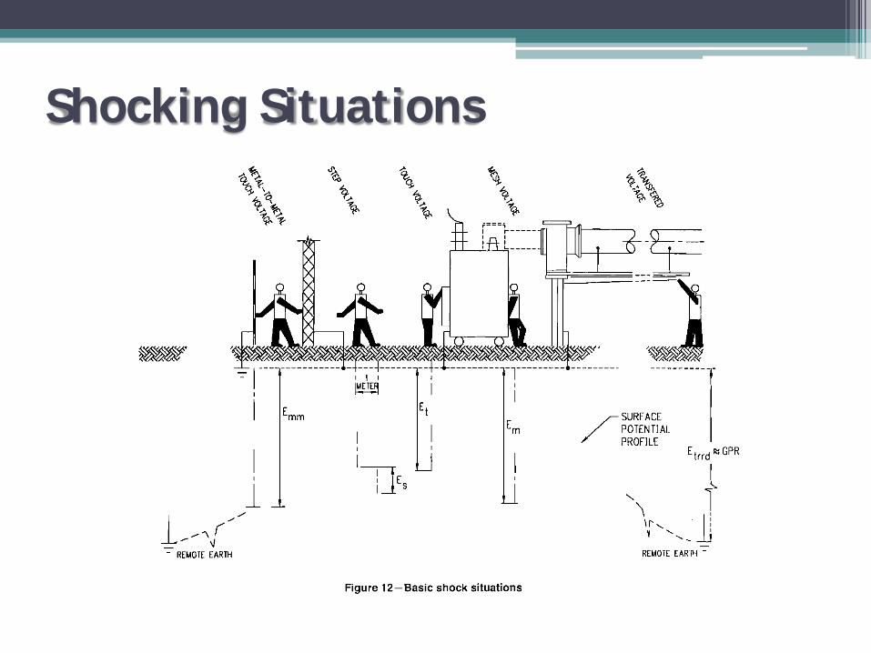
Shocking Situations

Transferred Potential
Designing Safe Grounding Systems
• The Ground System Must▫ Assure continuity of service▫ Limit the effects of potential gradients to safe levels under normal
and fault conditions▫ Limit voltage imposed by lightning, line surges or unintentional
contact with higher voltage lines▫ Stabilize the voltage to earth during normal operation▫ Provide an effective ground fault current path

Select Definitions
• Ground Potential Rise (GPR) – The maximum electrical potential that a substation grounding grid may attain relative to a distant point assumed to be remote earth. ▫ GPR = grid resistance x maximum grid current▫ Safety not necessarily dependant on GPR; a safe system could
have a high GPR with low gradients
• Step Voltage – The difference in surface potential experienced by a person bridging a distance of 1 meter with the feet without contacting any grounded object
• Touch Voltage – The potential difference between the GPR and the surface potential where a person is standing with one hand on a grounded surface
Select Definitions Continued
• Metal-to-Metal Touch Voltage – The potential difference between metallic objects within the substation site that may be bridged by direct contact▫ Assumed negligible in conventional substations if both items are
tied to the grid▫ Could be substantial with contact between grounded and
ungrounded object such as an isolated fence, water pipe or rail line
• Transferred Voltage – Special case where a voltage is transferred into or out of a substation
• Touch Voltage – The potential difference between the GPR and the surface potential where a person is standing with one hand on a grounded surface
Information for Modeling
• Soil Parameters• System Parameters• Conductor Properties• Ground System Arrangement (iterative)
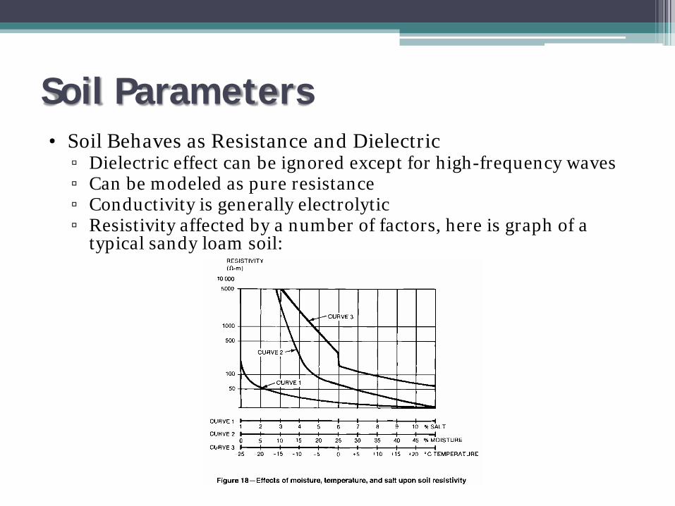
Soil Parameters• Soil Behaves as Resistance and Dielectric
▫ Dielectric effect can be ignored except for high-frequency waves▫ Can be modeled as pure resistance▫ Conductivity is generally electrolytic▫ Resistivity affected by a number of factors, here is graph of a
typical sandy loam soil:

Surfacing
• Proper Surfacing is Extremely Valuable▫ Typically 3 to 6 inches thick▫ Helps eliminate soil dryout▫ Reduces shock current Decreases ratio of body to short circuit current by 10 to 20
times, depending on surfacing resistivity▫ Resistivity is often provided by surfacing supplier or determined
by tested▫ Typical values are indicated on next page

SurfacingDescription Ω·m Dry Ω·m Wet
Crusher run granite (NC) 140 x 106 1,300
1.5” Crusher run granite with fines (GA)
4000 1,200
¾ - 1” Granite with fines (CA) - 6,513
#4 Washed granite (GA) 1.5 to 4.5 x 10⁶
5,000
#3 Washed granite (GA) 2.6 to 3 x 10⁶
100,00
Washed limestone (MI) 7 x 10⁶ 2,000 to 3,000
Washed granite, similar to .75” gravel
2 x 10⁶ 10,000
Washed granite, similar to pea gravel
40 x 106 5,000
#57 Washed granite (NC) 190 x 106 8000
Asphalt 2 to 30 x 106
.1 to 6 x 10⁶
Concrete (oven dried, air cured is lower)
1 to 1,000 x 106
21 to 100
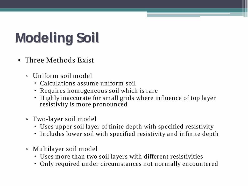
Modeling Soil• Three Methods Exist
▫ Uniform soil model Calculations assume uniform soil Requires homogeneous soil which is rare Highly inaccurate for small grids where influence of top layer
resistivity is more pronounced
▫ Two-layer soil model Uses upper soil layer of finite depth with specified resistivity Includes lower soil with specified resistivity and infinite depth
▫ Multilayer soil model Uses more than two soil layers with different resistivities Only required under circumstances not normally encountered
Bad Soil• Some Solutions for High Resistivity Soil
▫ Effectively increase the diameter of the conductors The soil closest to the electrode comprises the bulk of the
electrode ground resistance▫ Available methods Use of salts such as sodium chloride, calcium chloride to
treat soil around conductors May need to be replenished May be prohibited
Use of bentonite around conductors Hygroscopic Resistivity of 2.5 Ω·m when wet

Bad Soil Continued Use of chemical electrodes
Porous copper tube filled with salt Crammed in augured hole then
back-filled
Use of grounding enhancement material Very low resistivity (5% of bentonite) Contains aluminum silicates, carbon, quartz
and cements Claims of permanence and dry performance
Concrete and Steel• Concrete-Encased (Ufer) Electrodes:
• Lower Resistance▫ Wire or rod in concrete has lower resistance than when directly
buried
• Can corrode▫ Small DC currents can cause re-bar corrosion▫ Corroded re-bar can expand by 2.2X and damage footings▫ IEEE 80 gives a formula and a chart for predicting DC for various
soil conditions
• Are required by NEC?▫ Yes, for any “building or structure served”▫ 2005 NEC didn’t really change anything Replaced “if available on premises…” with “all that are present” Language changed to clarify intent

Concrete and Steel
• What About My Substation?▫ Is the facility served? Check
definition in NEC.▫ Ultimately it is up to the
authority having jurisdiction.▫ The intent of the NEC passage is
bonding of all present grounding to form a system
▫ In my view, the intent of passage is indicated to right:

Concrete and Steel
• IEEE 80▫ Gives equations and methodology for determining resistance of
concrete encased electrode (typically a rod enclosed in a cylinder)▫ Recommends the following Connect anchor bolt and angle stubs to the re-bar Reduce current duty and dc leakage by making sure primary
electrodes carry bulk of current Use ground enhancement material in high resistivity soil
around primary electrodes
Information for Modelling• Soil Parameters
• System Parameters• Conductor Properties• Ground System Arrangement (iterative)

Determining Maximum Grid Current IG
03II
S gf =
gfG IDI ×=
• Determine Type and Location of Worst-Case Fault
• Define Current Division Factor Sf▫ Define Ig
• Determine, for Each Fault, the Decrement Factor Df
• Select the Largest Product of Df x Ig• Where:
▫ Sf is the fault current division factor▫ If is the rms symm. Ground fault
current in A▫ Ig is the rms symm. grid current in
A▫ I0 is the zero-sequence system fault
current in A▫ IG is the maximum grid current in
A for a fault duration tf▫ Df is the decrement factor in s
ffg ISI ×=
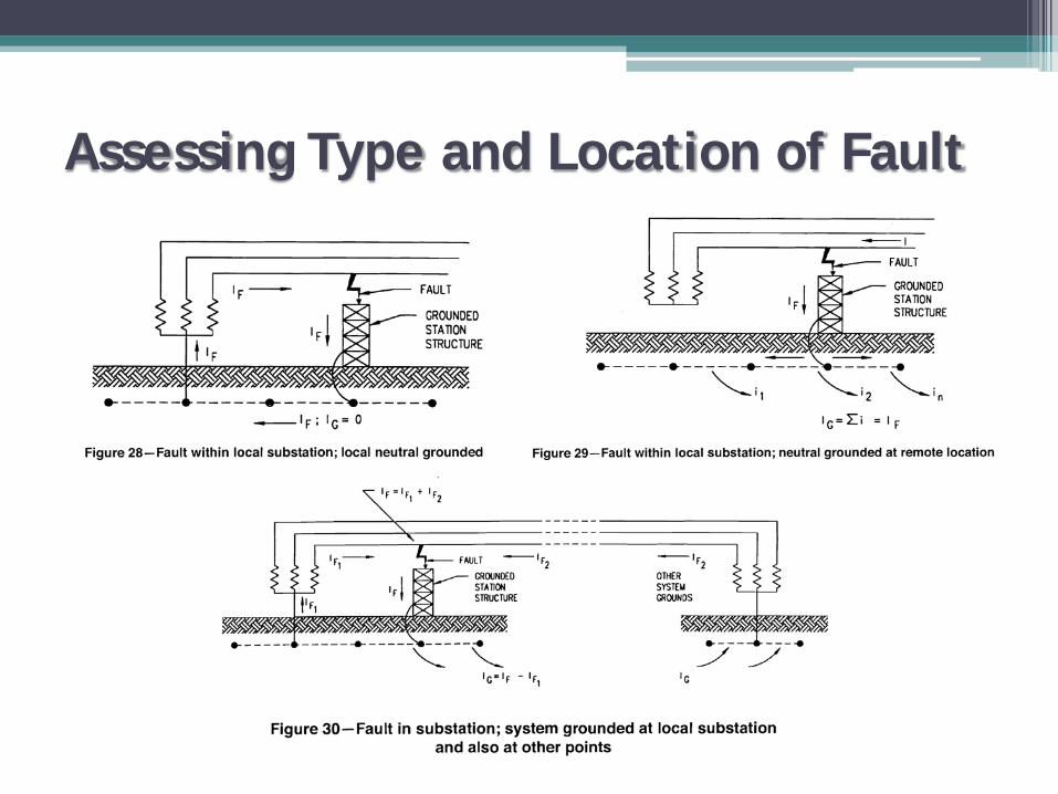
Assessing Type and Location of Fault

Information for Modelling• Soil Parameters• System Parameters
• Conductor Properties• Ground System Arrangement (iterative)
Selecting Grounding Components
• Grounding Materials Must:▫ Have sufficient conductivity - determined by grounding
calculations▫ Resist fusing and mechanical deterioration during faults ▫ Be mechanically reliable and rugged▫ Be able to maintain function when exposed to corrosion or abuse
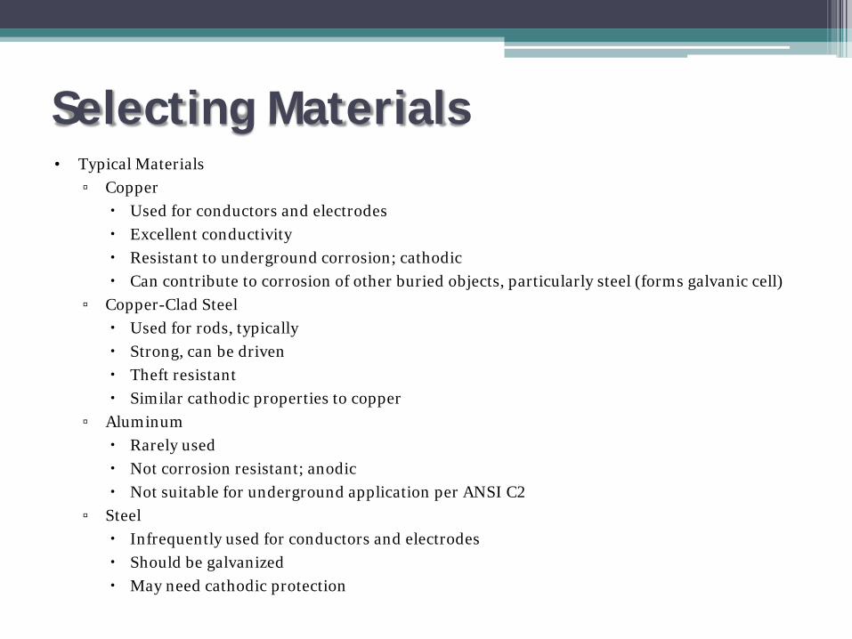
Selecting Materials• Typical Materials
▫ Copper Used for conductors and electrodes Excellent conductivity Resistant to underground corrosion; cathodic Can contribute to corrosion of other buried objects, particularly steel (forms galvanic cell)
▫ Copper-Clad Steel Used for rods, typically Strong, can be driven Theft resistant Similar cathodic properties to copper
▫ Aluminum Rarely used Not corrosion resistant; anodic Not suitable for underground application per ANSI C2
▫ Steel Infrequently used for conductors and electrodes Should be galvanized May need cathodic protection

More on Sizing
cfkcmil tKIA ⋅=
• IEEE 80 Containing Charts for the Variables Based On Conductor TypeFrom these charts, it can be determined that:
Where:Akcmil is the area of the conductortc is the duration of current in sKf is a constant from Table 2 in IEEE 80 at various values
of Tm(see next)
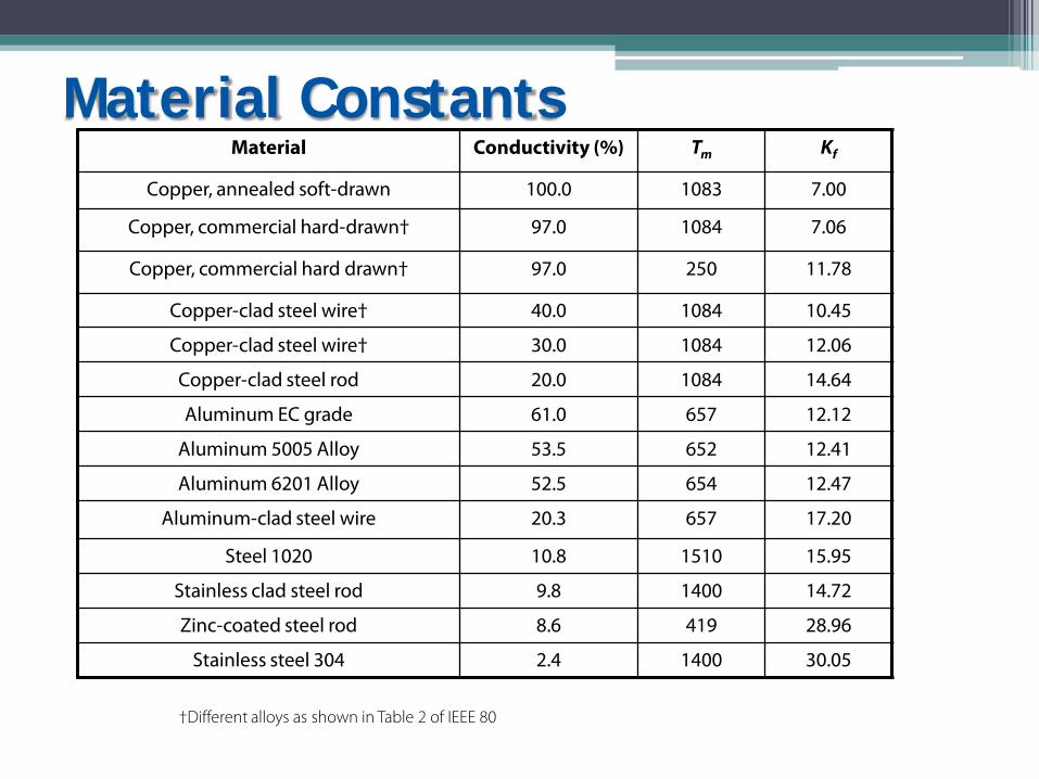
Material Constants
†Different alloys as shown in Table 2 of IEEE 80
Material Conductivity (%) Tm Kf
Copper, annealed soft-drawn 100.0 1083 7.00
Copper, commercial hard-drawn† 97.0 1084 7.06
Copper, commercial hard drawn† 97.0 250 11.78
Copper-clad steel wire† 40.0 1084 10.45
Copper-clad steel wire† 30.0 1084 12.06
Copper-clad steel rod 20.0 1084 14.64
Aluminum EC grade 61.0 657 12.12
Aluminum 5005 Alloy 53.5 652 12.41
Aluminum 6201 Alloy 52.5 654 12.47
Aluminum-clad steel wire 20.3 657 17.20
Steel 1020 10.8 1510 15.95
Stainless clad steel rod 9.8 1400 14.72
Zinc-coated steel rod 8.6 419 28.96
Stainless steel 304 2.4 1400 30.05

Connections• Connections Are Critical Components of the Grounding System
▫ Should meet the general requirements set forth for conductors Conductivity Corrosion resistance Current carrying capacity Mechanical strength Withstand faults Heating Magnetic Forces
• IEEE 837 Provides Testing Guidelines for Grounding Connections

Types of Connectors
• Typical Connector Types▫ Compression▫ Exothermic▫ Mechanical
• Some Considerations▫ Will this need to be removed?▫ Does my connector need to be tested per IEEE 837?▫ Are special permits or precautions required at the site?▫ Where is the connection going to be located?

Connections• Compression
▫ Typically applied with portable hydraulic compression tool▫ Wide applicability, e.g. Cable to cable Cable to rod or re-bar Cable to terminal Can be used Above grade Below grade In concrete
▫ Irreversible▫ Manufacturer’s tout Safety versus exothermic Strength Conductivity Irreversibility

Connections• Exothermic
▫ Installed using mold (graphite for multi-use, ceramic for single use), weld powder (shot) and a flint igniter
▫ Wide applicability, e.g. Cable to cable Cable to rod or re-bar Cable to virtually anything Locations
Above grade Below grade In concrete
▫ Irreversible▫ Manufacturer’s tout
Strength Conductivity Irreversibility
▫ Some stalwart compression manufacturers now make exothermic products
▫ Some plants require hot work permit – releases energy

Connections• Mechanical
▫ Bolted, typically copper or bronze fittings, often tin plated▫ Varied applicability:
Cable to cable Cable to rod or re-bar Locations
Above grade Below grade In concrete
▫ Reversible▫ Manufacturer’s tout
Ease of installation Conductivity Irreversibility

The IEEE 80 Twelve-Step Method
• 1. Determine Area From Layout, Determine Soil Resistivity• 2. Determine Minimum Conductor Size• 3. Calculate Tolerable Step and Touch Potential• 4. Lay Out Preliminary Substation Grid, Loop Around Yard, Sufficient
Equipment Taps• 5. Determine Preliminary Resistance of Grounding System• 6. Determine Grid Current• 7. Determine GPR. If Less than Tolerable Touch Voltage, Done.
Otherwise:• 8. Calculate Mesh and Step Voltages.• 9. If Mesh Voltage is Below Tolerable Touch Voltage, Done. Otherwise:• 10. Check Step Voltage. If Below Tolerable Level, Done. Otherwise:• 11. Revise Grid.• 12. Complete Detailed Design.
Information for Modelling
• Soil Parameters• System Parameters• Conductor Properties
• Ground System Arrangement (iterative)
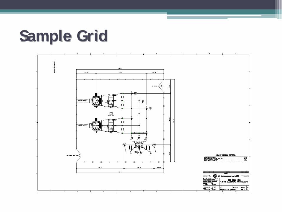
Sample Grid
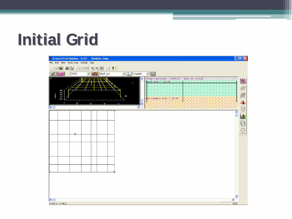
Initial Grid

It Didn’t Work (As Expected)
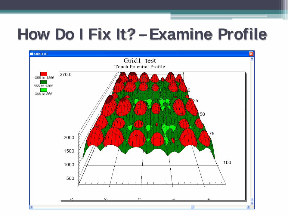
How Do I Fix It? – Examine Profile

Enhance Design
• Numerous Areas Over Touch Limit• What Can Be Done?
▫ Relaying can be modified to clear faults more quickly▫ A more accurate value for Sf can be determined▫ Rods can be added or lengthened▫ Conductor can be added▫ GEM can be added▫ Grid depth can be adjusted
• What Can Be Done for This Grid?▫ Solution based on experience and feel▫ The lower soil is less resistive in this case so let’s add rods▫ The sub is small so it is understood that grid spacing will be tight
so we could add copper▫ Sf can be adjusted. This sub is connected with two static wires.
Transformers have delta primaries.
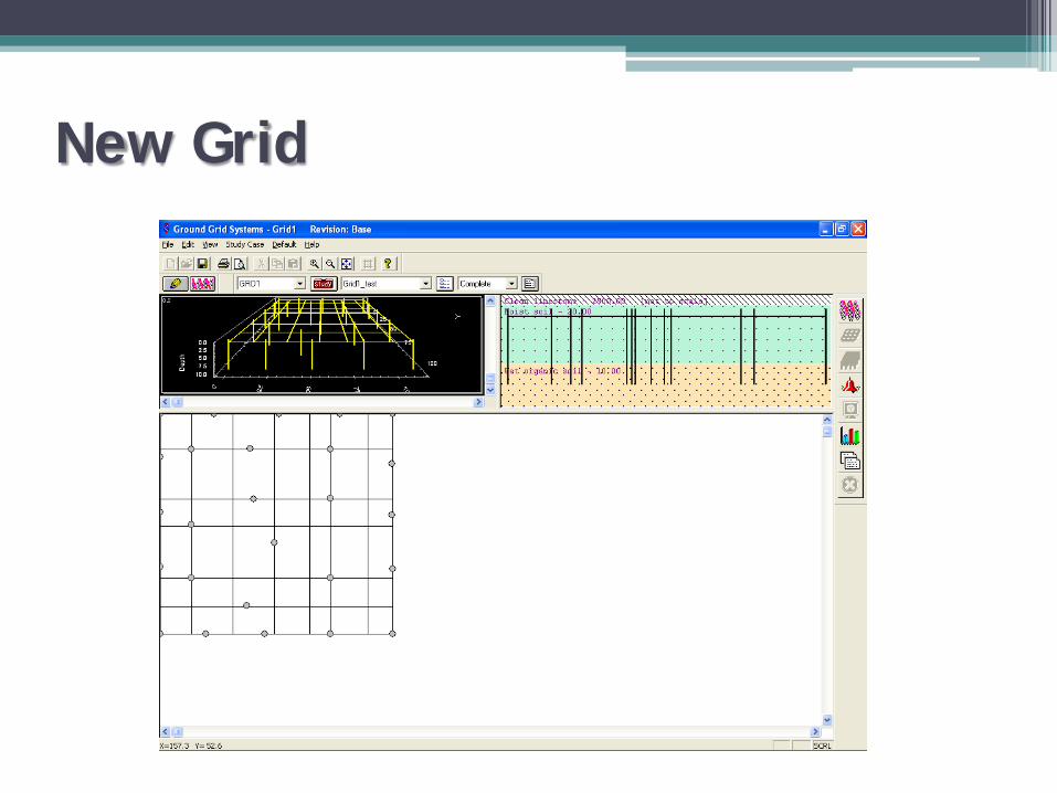
New Grid
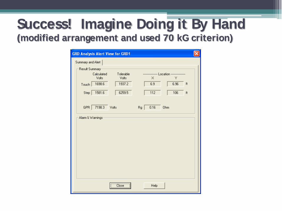
Success! Imagine Doing it By Hand(modified arrangement and used 70 kG criterion)

Finished
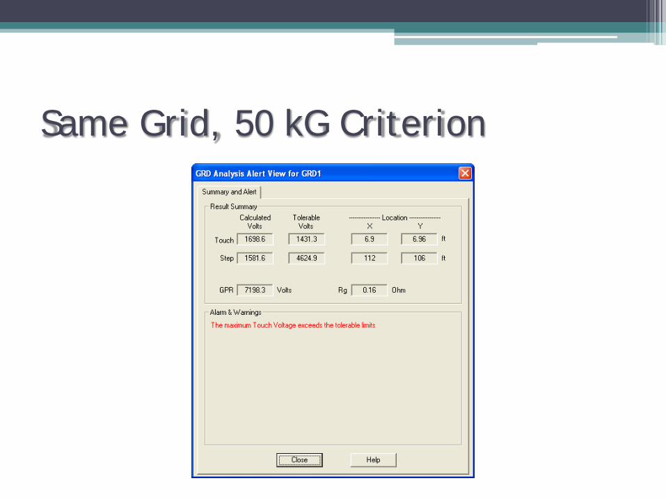
Same Grid, 50 kG Criterion

Same Grid with 2’ Surfacing
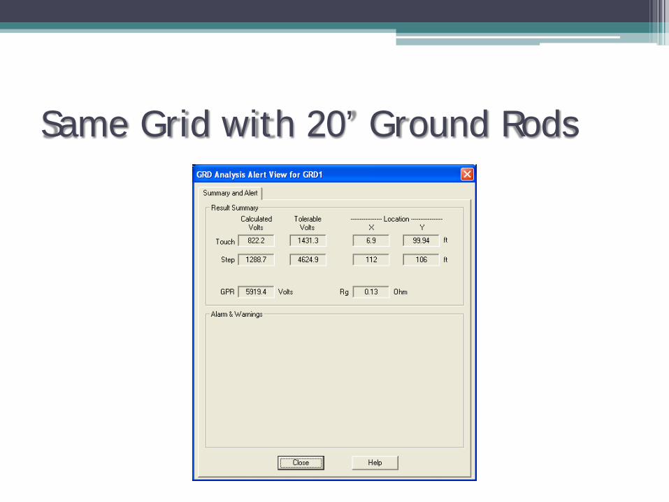
Same Grid with 20’ Ground Rods
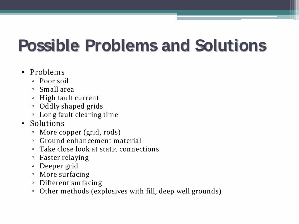
Possible Problems and Solutions• Problems
▫ Poor soil▫ Small area▫ High fault current▫ Oddly shaped grids▫ Long fault clearing time
• Solutions▫ More copper (grid, rods)▫ Ground enhancement material▫ Take close look at static connections▫ Faster relaying▫ Deeper grid▫ More surfacing▫ Different surfacing▫ Other methods (explosives with fill, deep well grounds)
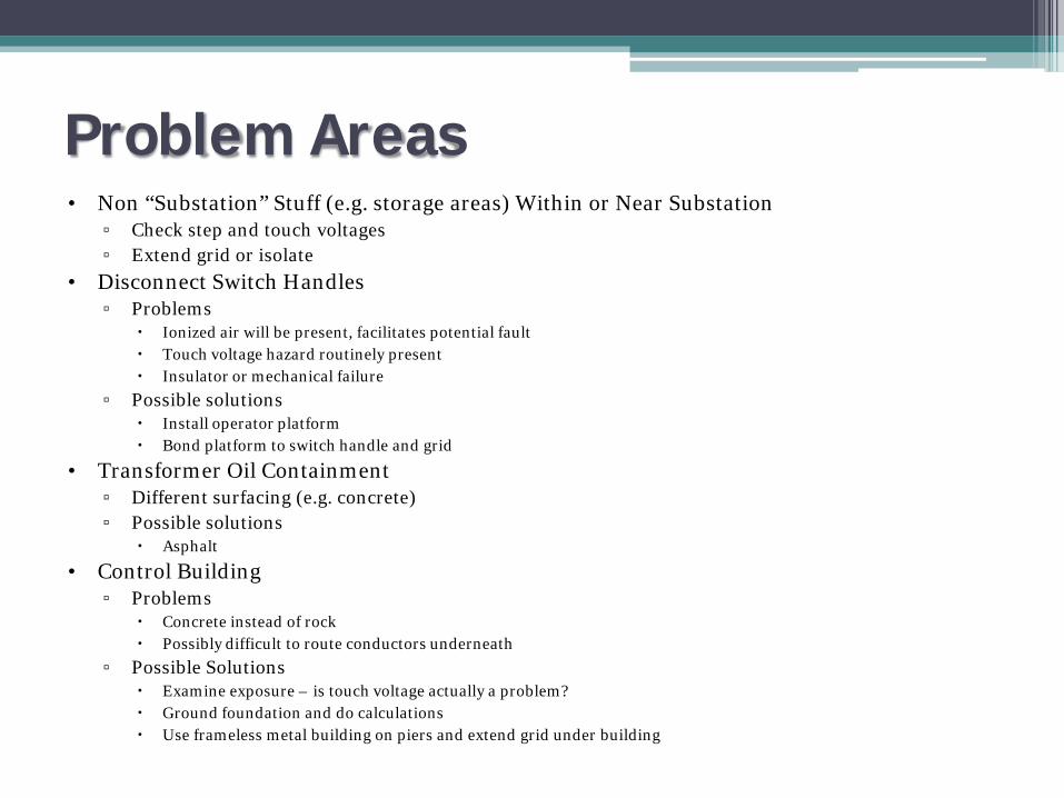
Problem Areas• Non “Substation” Stuff (e.g. storage areas) Within or Near Substation
▫ Check step and touch voltages▫ Extend grid or isolate
• Disconnect Switch Handles▫ Problems
Ionized air will be present, facilitates potential fault Touch voltage hazard routinely present Insulator or mechanical failure
▫ Possible solutions Install operator platform Bond platform to switch handle and grid
• Transformer Oil Containment▫ Different surfacing (e.g. concrete)▫ Possible solutions
Asphalt
• Control Building▫ Problems
Concrete instead of rock Possibly difficult to route conductors underneath
▫ Possible Solutions Examine exposure – is touch voltage actually a problem? Ground foundation and do calculations Use frameless metal building on piers and extend grid under building
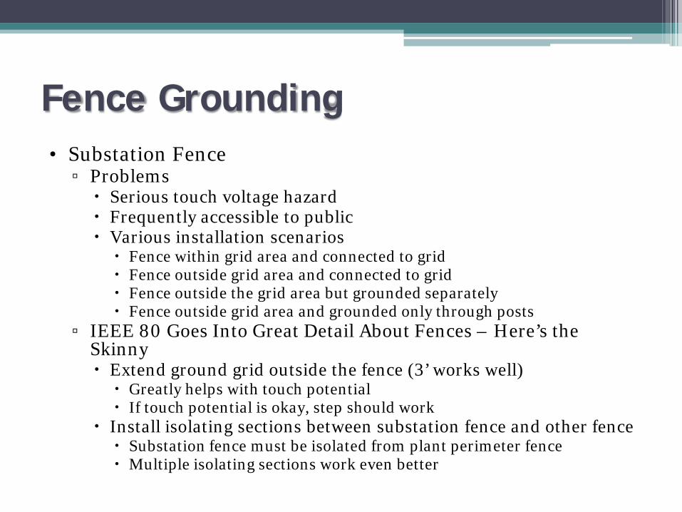
Fence Grounding• Substation Fence
▫ Problems Serious touch voltage hazard Frequently accessible to public Various installation scenarios Fence within grid area and connected to grid Fence outside grid area and connected to grid Fence outside the grid area but grounded separately Fence outside grid area and grounded only through posts
▫ IEEE 80 Goes Into Great Detail About Fences – Here’s the Skinny Extend ground grid outside the fence (3’ works well) Greatly helps with touch potential If touch potential is okay, step should work
Install isolating sections between substation fence and other fence Substation fence must be isolated from plant perimeter fence Multiple isolating sections work even better
GIS Continued• IEEE 80 Gives a Cursory Glance at GIS
▫ Definitions▫ Special problems Small size High-frequency transients
▫ Circulating Currents Induced voltages from current flow in phase conductor Continuous vs. non-continuous enclosures
▫ Foundations General Rule – Include the slab
▫ Summary Follow manufacturer’s instructions

Testing Ground Systems• Defined in IEEE 81• Compare Results to Calculated Values• Methods of Testing
▫ Two-point method Resistance of system and an auxiliary ground Not particularly accurate
▫ Three-point method Uses two test electrodes and one station ground Inaccurate for large substations
▫ Staged-fault tests High-current test – Inject current then measure voltage
▫ Fall-of-potential method Measure resistance of system relative to remote electrode Most widely used