group 21 transmissions - jholst.netjholst.net/70-service-manual/transmission.pdf · depressing the...
TRANSCRIPT
A GROUP 21
TRANSMISSIONS CONTENTS
Page Page MANUAL TRANSMISSIONS—3 SPEED . . . 54 TIGHTENING REFERENCE 10 SPECIFICATIONS 89 TORQUEFLITE TRANSMISSIONS 1
TORQUEFL1TE TRANSMISSION (A-727-B)
INDEX Page
General Information . . . . . . 1 Hydraulic Control System 11 Operating Instructions 12 Serv ice Diagnosis 12 Service in Vehicle . . . . . . . . . . . . . . . . . . . . . 18
Air Pressure Tes ts 25 Aluminum Thread Repair 18 Band Adjustments 22 Console Gearshif t 20 Extension Housing and Output Shaft Bearing . . 26 Extension Housing Yoke Sea l 26 Gearshift Linkage Adjustment 19 Governor 27 Hydraulic Control Pressure Tes ts 22 Hydraulic Control Pressure Adjustments 24 Lubrication 19 Neutral Starting Switch 21 Parking Lock Components 28 Speedometer Pinion — 26 Throttle Rod Adjustment 22 Valve Body and Accumulator Piston 29
Service Out of Vehicle 29 Assembly—Sub-Assembly Installation 48
GENERAL INFORMATION T h e TorqueF l i t e T ransmiss ion model identification
mark ings are cast in ra ised letters about 3 / 8 inch high on the lower left side of the t ransmission be l l housing.
T h e A-727-B TorqueF l i t e T ransmiss ion serv ic ing procedures are in genera l the same for a l l models. C A U T I O N : T ransmiss ion operation requirements are different for each vehicle and engine combination and some internal parts will be different to provide for this. There fore , when replacing parts, refer to the seven digit part number stamped on left side of the t ransmiss ion oil pan flange.
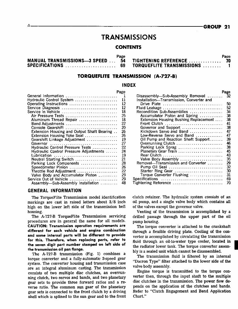
T h e A-727-B t ransmission (F ig. 1) combines a torque converter and a fully-automatic 3-speed gear system. T h e converter housing and t ransmission case are an integral a luminum casting. T h e t ransmission consists of two mult iple disc c lutches, a n overrunn ing c lu tch , two servos and bands, and two planetary gear sets to provide three forward ratios and a reverse ratio. T h e common s u n gear of the planetary gear sets is connected to the front c lutch by a dr iv ing she l l w h i c h is spl ined to the s u n gear and to the front
Page D isassembly—Sub-Assembly Removal 32 Instal lat ion—Transmission, Converter and
Drive Plate 50 Fluid Leakage 52 Recondition Sub-Assembl ies . . . . . . . . . . . . . . . . . 34
Accumulator Piston and Spr ing 38 Extension Housing Bushing Replacement 38 Front Clutch 41 Governor and Support 38 Kickdown Servo and Band 47 Low-Reverse Servo and Band 47 Oil Pump and Reaction Shaf t S u p p o r t . . . . . . . 39 Overrunning Clutch 46 Parking Lock Sprag 38 Planetary Gear Train 45 Rear Clutch 43 Valve Body Assembly . . . . . . . . . . . . . . . . . . . . . . 35
Removal—Transmiss ion and Converter 29 Pump Oil Sea l 32 Starter Ring Gear 30 Torque Converter F lushing 31
Specif icat ions 69 Tightening Reference 70
c lutch retainer. T h e hydrau l ic system consists of an oil pump, and a single valve body w h i c h contains a l l of the valves except the governor valve.
Ven t ing of the t ransmission is accompl ished by a dr i l led passage through the upper part of the oi l pump housing.
T h e torque converter is attached to the crankshaf t through a flexible dr iv ing plate. Cool ing of the conver ter is accompl ished by c i rculat ing the transmission fluid through an oil-to-water type cooler, located in the radiator lower tank. T h e torque converter assembly is a sealed unit wh ich cannot be disassembled.
T h e t ransmission fluid is filtered by an internal "Dacron T y p e " filter attached to the lower side of the valve body assembly.
E n g i n e torque is t ransmit ted to the torque conver ter then, through the input shaft to the mult iple disc c lutches i n the t ransmission. T h e power flow depends on the application of the c lutches and bands. R e f e r to " C l u t c h Engagement and B a n d Appl icat ion C h a r t . "

FLEXIBLE DRIVE PLATE
ENGINE C R A N K S H A F T NN116B
Fig. I— TorqueFlite Transmission and Torque Converter (A-727)

A — -TORQUEFL ITE—TRANSMISSION 21
E N G I N E R U N N I N G
NN34C Park Hydraulic Circuits
ENGINE iUNNSNG
Neutral Hydraulic Circuits
HH35C

21-4 TRANSMISSION—TORQUEFLITE
Drive-Breakaway Mydmmim Circuits
A , TORQUEFLITE—TRANSMISSION 21-5
ftEAft C i U i C H
SERVO
• H I CLUTCH
TO LUB.
PUMP
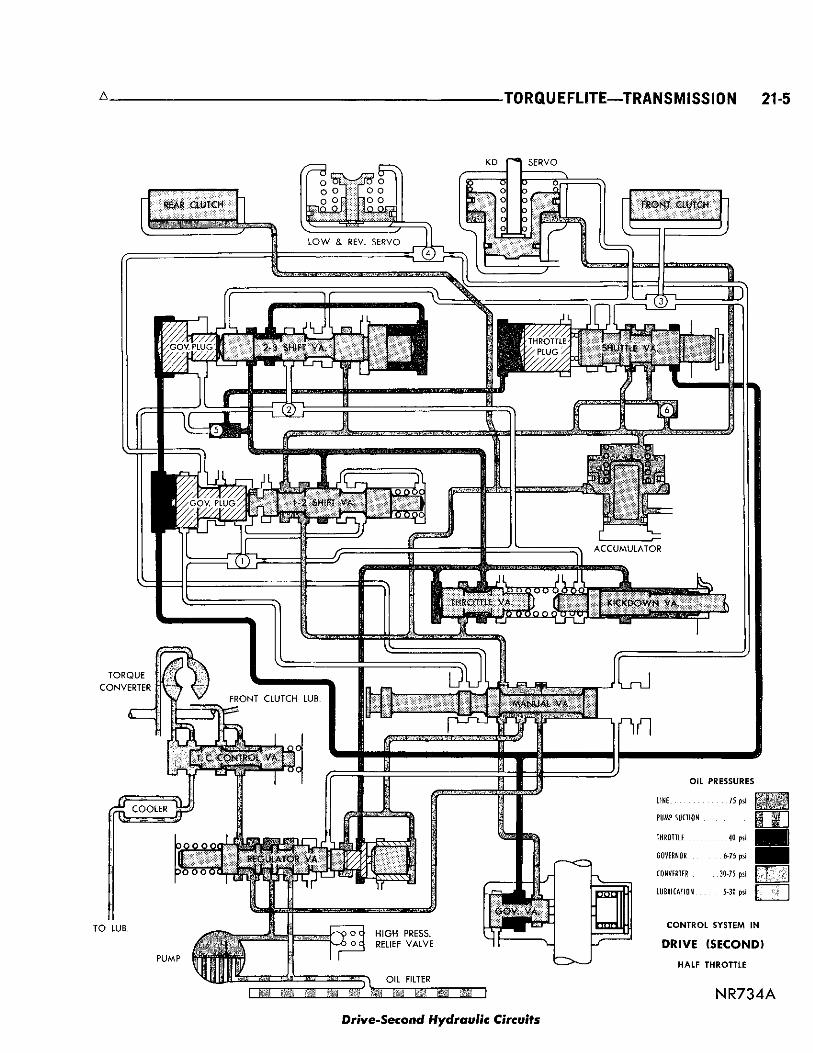
CONVERTER 30-75 psi | "
L U B R I C A T I O N . . . . . . . 5-30 psi j ~ j
CONTROL SYSTEM IN
DRIVE (SECOND)
HALF THROTTLE
N R 7 3 4 A
Drive-Second Hydraulic Circuits

21-6 TRANSMISSION—TORQUEFLITE
Drive-Direct Hydraulic Circuits

A — — T O R Q U E F L I T E — T R A N S M I S S I O N 21-7
Drive-Kiekdown Hydraulic Circuits
21-8 TRANSMISSION—TORQUEFLITE A
REAR CIUICH
S E R V O
I T. C CONTROL VA. j
-^^yj, * . . . , ^ 0
Pi C O O L E R
Jo O O CM
I&GUIATOR
TO LUB.
P U M P
OIL PRESSURES
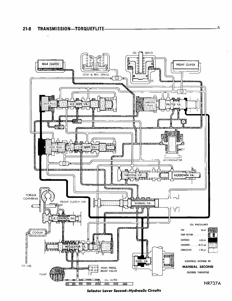
55 psi
^ 9 ° ° HIGH PRESS. ^ o c RELIEF VALVE
LINE
PUMP SUCTION
GOVERNOR 6-55 psi
CONVERTER 30-75 psi
LUBRICATION 5-30 psi J
CONTROL SYSTEM IN
MANUAL SECOND CLOSED THROTTLE
OIL FILTER
• N R 7 37A
Selector Lever Second—Hydraulic Circuits

A TORQUEFLITE—TRANSMISSION 21-9
Selector Lever Low—Hydraulic Circuits

21-10 TRANSMISS10N—T0RQUEFL1TE A
Reverse Hydraulic Circuits
A TORQUEFLITE—TRANSMISSION 21-11
HYDRAULIC CONTROL SYSTEM
T h e hydrau l ic control c i rcui ts on pages 3 through 10 show the position of the var ious valves wi th color coded passages to indicate those under hydrau l ic pressure for a l l operations of the t ransmission.
T h e hydrau l ic control system makes the t ransmission ful ly automatic, and has four important funct ions to per form. I n a genera l way, the components of any automatic control system may be grouped into the following basic groups:
T h e p ressure supply system, the pressure regulating valves, the flow control valves, and the c lutches and band servos.
T a k i n g each of these basic groups or systems in turn , the control system may be descr ibed as follows:
Pressure Supply System T h e p r e s s u r e supply system consists of an oil pump
dr iven by the engine through the torque converter . T h e single f ront pump furn ishes pressure for al l the hydraul ic and lubr icat ion requirements.
Pressure Regulating Valves T h e pressure regulat ing valves consist of a regu
lator valve w h i c h controls l ine pressure at a value dependent on throttle opening.
T h e torque converter control valve maintains torque converter operating pressure and t ransmission lubricat ing pressure .
T h e governor valve t ransmits regulated pressure to
the t ransmission (in conjunct ion wi th throttle pressure) to control upshift and downshift speeds.
T h e throttle valve t ransmits regulated pressure to the t ransmission (in conjunct ion wi th governor pressure) to control upshift and downshift speeds.
Flow Control Valves T h e m a n u a l valve obtains the different t ransmis
sion dr ive ranges as selected by the vehic le operator. T h e 1-2 shift valve automatical ly shifts the trans
mission f rom low to second or f rom second to low depending on the vehicle operation.
T h e 2-3 shift valve automatical ly shifts the transmission f rom second to direct or f rom direct to second depending on the vehicle operation.
T h e k ickdown valve makes possible a forced downshift f rom direct to second-second to breakaway or direct to breakaway (depending on vehic le speed) by depressing the accelerator pedal past the detent " fee l " near wide open throttle.
T h e shutt le valve has two separate funct ions and performs each independently. T h e first is that of providing fast re lease of the k ickdown band, and smooth front c lutch engagement w h e n the dr iver makes a "lift-foot" upshift f rom second to direct. T h e second funct ion of the shutt le valve is to regulate the application of the k ickdown servo and band w h e n mak ing direct to second k ickdowns.
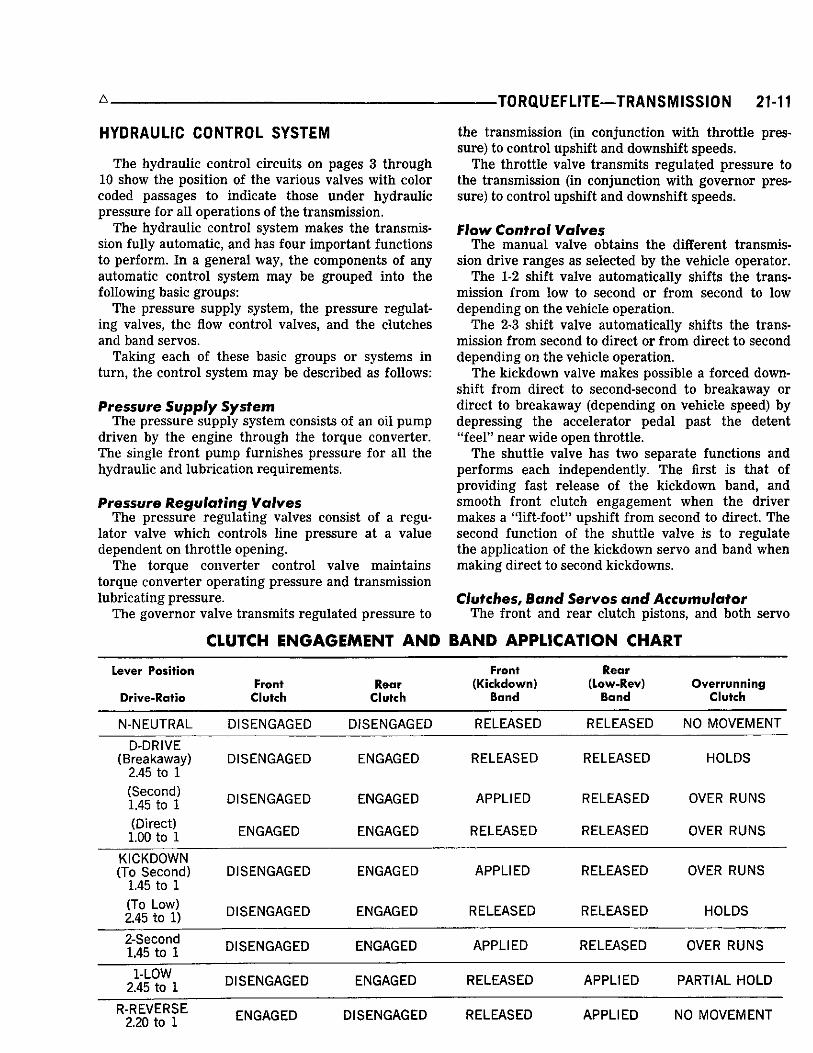
Clutches, Band Servos and Accumulator T h e front and rear c lutch pistons, and both servo
CLUTCH ENGAGEMENT AND BAND APPLICATION CHART
Lever Position
Drive-Ratio Front
Clutch Rear
Clutch
Front (Kickdown)
Band
Rear (Low-Rev)
Band Overrunning
Clutch
N - N E U T R A L D I S E N G A G E D D I S E N G A G E D R E L E A S E D R E L E A S E D NO MOVEMENT
D-DRIVE (Breakaway)
2.45 to 1 D I S E N G A G E D E N G A G E D R E L E A S E D R E L E A S E D H O L D S
(Second) 1.45 to 1 D I S E N G A G E D E N G A G E D A P P L I E D R E L E A S E D OVER R U N S
(Direct) 1.00 to 1 E N G A G E D E N G A G E D R E L E A S E D R E L E A S E D OVER R U N S
KICKDOWN (To Second)
1.45 to 1 D I S E N G A G E D E N G A G E D A P P L I E D R E L E A S E D OVER R U N S
(To Low) 2.45 to 1) D I S E N G A G E D E N G A G E D R E L E A S E D R E L E A S E D H O L D S
2-Second 1.45 to 1 D I S E N G A G E D E N G A G E D A P P L I E D R E L E A S E D OVER R U N S
1-LOW 2.45 to 1 D I S E N G A G E D E N G A G E D R E L E A S E D A P P L I E D P A R T I A L HOLD
R - R E V E R S E 2.20 to 1 E N G A G E D D I S E N G A G E D R E L E A S E D A P P L I E D NO MOVEMENT

21-12 TRANSMISSION—TORQUEFLITE - A
SHIFT PATTERN SUMMARY CHART Car Speed To Axle Ratios
Chrysler Imperial 2.76:1 3.23:1 2.94:1 Condition
Closed Throttle 1-2 Upshift . Closed Throttle 2-3 Upshift . Wide Open Throttle 1-2 Upshift Wide Open Throttle 2-3 Upshift 3-2 Kickdown Limit 3-1 Kickdown Limit Closed Throttle Downshift
pistons are moved hydraul ica l ly to engage the clutches and apply the bands. T h e pistons are released by spr ing tension w h e n hydrau l ic pressure is re leased. O n the 2-3 upshift , the k ickdown servo piston is re leased by spr ing tension and hydrau l ic pressure .
T h e accumulator controls the hydrau l ic pressure on the apply side of the k ickdown servo dur ing the 1-2 shift; thereby, cushioning the k ickdown band application at any throttle position.
OPERATING INSTRUCTIONS
T h e t ransmiss ion wi l l automatical ly upshif t and downshift at approximately the mi les per hour given i n the Shift Pa t te rn S u m m a r y Char t . All shift speeds given in the "Chart" may vary somewhat due to production tolerances and rear axle ratios. The quality of the shif ts Is very important. All shi f ts should be smooth, responsive, and with no noticeable engine runaway.
Gearshift and Parking Lock Controls T h e t ransmiss ion is control led by a " lever type"
gearshif t incorporated wi th in the steer ing co lumn. T h e control has s ix selector lever positions: P (park), R (reverse), N (neutral) , D (drive), 2 (second) a n d 1 (low). Some vehic les are equipped wi th a " lever type" console gearshif t w h i c h has the same selector lever positions. T h e park ing lock is appl ied by moving the selector lever past a gate to the P position. CAUTION: Never apply the parking lock until the vehicle has stopped; otherwise, a severe ratcheting noise will occur.
8-14 7-13 742 14-19 13-18 12-16 33-52 31-49 28-44 77-90 72-85 66-77 66-31 62-76 56-69 30-34 28-32 25-29 6-13 6-12 5-11
Starting Engine T h e engine wi l l start wi th the selector lever in
e i ther the P (park) or N (neutral) positions. (1) A s a safety precaut ion w h e n start ing in the N
(neutral) position, apply the park ing or foot brake. (2) Depress the accelerator pedal one-third of
t rave l to insure proper choke operation. (3) T u r n the ignition key al l the way to the r ight to
S T A R T position. W h e n the engine starts, re lease the key and it wi l l re turn to the O N position.
The TorqueFlite transmission will not permit starting the engine by pushing or towing.
Mountain Driving W h e n dr iv ing in the mountains wi th ei ther heavy
loads or w h e n pul l ing t ra i lers , the 2 (second) or 1 (low) position should be selected on upgrades w h i c h requi res heavy throttle for 1/2 mile or more. T h i s reduces the possibil ity of overheating the t ransmission and converter under these conditions.
Towing Vehicle Transmission Inoperative: T o w the vehic le wi th a
r e a r end p ickup or remove the propel ler shaft. Transmission Operating Properly: T h e vehicle may
be towed safely in N (neutral) wi th rear wheels on the ground at a speed not to exceed 30 mph. If the vehicle is to be towed for extended distances, it should be done with a rear end pickup or the propeller shaft removed. B e c a u s e the t ransmission rece ives lubr icat ion only w h e n the engine is runn ing , it is good practice to always tow a disabled vehicle with a rear end pickup or remove the propel ler shaft .
SERVICE DIAGNOSIS The t ransmission should not be removed nor d i s a s s e m b l e d until a careful diagnosis is made, the definite c a u s e determined and all possible external correct ions performed. In diagnosing any abnormal shift condition, a lways make the hydraul ic pressure tests before d isassembly or replacement of parts.
Condition Possible Cause Correction
H A R S H E N G A G E M E N T (a) Engine idle speed too high. (a) Adjust engine idle speed to speci f ica-IN D, 1, 2 AND R tions. Re-adjust throttle linkage.
(b) Hydraulic pressures too high or low. (b) Inspect fluid level, then perform hydraulic pressure tests and adjust to specif ications.
-TORQUEFLITE—TRANSMISSION 21-13
Condition Possible Cause Correction
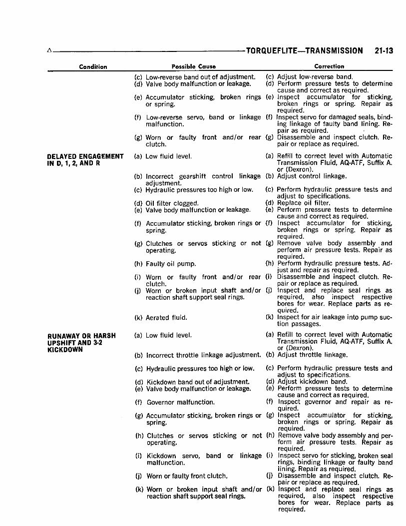
D E L A Y E D E N G A G E M E N T IN D, 1 ,2, AMD R
RUNAWAY OR H A R S H U P S H I F T AND 3-2 KICKDOWN
(c) Low-reverse band out of ad jus tment (d) Valve body malfunction or leakage.
(e) Accumulator st icking, broken rings or spring.
(f) Low-reverse servo, band or linkage malfunction.
(g) Worn or faulty front and /or rear c lutch.
(a) Low fluid level.
(b) Incorrect gearshift control linkage adjustment.
(c) Hydraulic pressures too high or low.
(d) Oil filter clogged. (e) Valve body malfunction or leakage.
(f) Accumulator st icking, broken rings or spring.
(g) C lu tches or servos st icking or not operating.
(h) Faulty oil pump.
(i) Worn or faulty front and /or rear c lutch.
(j) Worn or broken input shaft and /or reaction shaft support sea l rings.
(k) Aerated fluid.
(a) Low fluid level.
(b) Incorrect throttle linkage adjustment.
(c) Hydraulic pressures too high or low.
(d) Kickdown band out of adjustment. (e) Valve body malfunction or leakage.
(f) Governor malfunction.
(g) Accumulator st icking, broken rings or spring.
(h) C lu tches or servos st icking or not operating.
(i) Kickdown servo, band or linkage malfunction.
(j) Worn or faulty front c lutch.
(k) Worn or broken input shaft a n d / o r reaction shaft support sea l rings.
(c) Adjust low-reverse band. (d) Perform pressure tests to determine
c a u s e and correct a s required. (e) Inspect accumulator for sticking,
broken rings or spring. Repair a s required.
(f) Inspect servo for damaged sea ls , binding linkage of faulty band lining. Repair a s required.
(g) D isassemble and inspect clutch. Repair or replace a s required.
(a) Refill to correct level with Automatic Transmiss ion Fluid, AQ-ATF, Suffix A. or (Dexron).
(b) Adjust control linkage.
(0 (d) (e)
(f)
(g)
(h)
(i)
(j)
(k)
Perform hydraulic pressure tests and adjust to specif icat ions. Replace oil filter. Perform pressure tests to determine cause and correct a s required. Inspect accumulator for sticking, broken rings or spring. Repair a s required. Remove valve body assembly and perform air pressure tests. Repair a s required. Perform hydraulic pressure tests. Adjust and repair as required. D isassemble and inspect c lutch. Repair or replace a s required. Inspect and replace seal rings a s required, a lso inspect respective bores for wear. Replace parts a s required. Inspect for air leakage into pump s u c tion passages .
(a) Refill to correct level with Automatic Transmiss ion Fluid, AQ-ATF, Suffix A. or (Dexron).
(b) Adjust throttle linkage.
(c) Perform hydraulic pressure tests and adjust to specif icat ions.
(d) Adjust kickdown band. (e) Perform pressure tests to determine
cause and correct a s required. (f) Inspect governor and repair a s re
quired. (g) Inspect accumulator for st icking,
broken rings or spring. Repair a s required.
(h) Remove valve body assembly and perform air pressure tests. Repair a s required.
(i) Inspect servo for st icking, broken sea l rings, binding linkage or faulty band lining. Repair a s required.
(j) D isassemble and inspect c lutch. Repair or replace a s required.
(k) Inspect and replace sea l rings a s required, a lso inspect respective bores for wear. Replace parts a s required.
21-14 TRANSMISSION—TORQUEFLITE
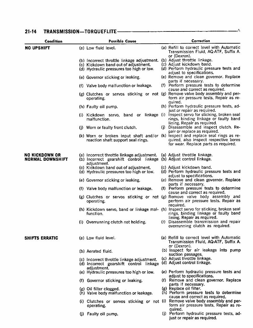
Condition Possible Cause NO U P S H I F T (a) Low fluid level. (a) Refill to correct level with Automatic
Transmiss ion Fluid, AQ-ATF, Suffix A. or (Dexron).
(b) Incorrect throttle linkage adjustment, (b) Adjust throttle linkage. (c) Kickdown band out of adjustment. (c) Adjust kickdown band. (d) Hydraulic pressures too high or low. (d) Perform hydraulic pressure tests and
adjust to specif icat ions. (e) Governor st icking or leaking. (e) Remove and clean governor. Replace
parts if necessary. (f) Valve body malfunction or leakage. (f) Perform pressure tests to determine
cause and correct a s required. (g) C lu tches or servos st icking or not (g) Remove valve body assembly and per-
operating. form air pressure tests. Repair a s required.
(h) Faulty oil pump. (h) Perform hydraulic pressure tests, adjust or repair a s required.
(i) Kickdown servo, band or linkage (i) Inspect servo for sticking, broken seal malfunction. rings, binding linkage or faulty band
lining. Repair a s required. (j) Worn or faulty front c lutch. (j) D isassemble and inspect c lutch. Re
pair or replace a s required. (k) Worn or broken input shaft and /or (k) Inspect and replace seal rings a s re-
reaction shaft support sea l rings. quired, a lso inspect respective bores for wear. Replace parts a s required.
Correction
NO KICKDOWN OR (a) Incorrect throttle linkage ad jus tment NORMAL D O W N S H I F T (b) Incorrect gearshift control linkage
adjustment. (c) Kickdown band out of a d j u s t m e n t (d) Hydraulic pressures too high or low.
(e) Governor st icking or leaking.
(f) Valve body malfunction or leakage.
(g) C lu tches or servos st icking or not operating.
(h) Kickdown servo, band or linkage malfunction.
(i) Overrunning clutch not holding.
(a) Adjust throttle linkage. (b) Adjust control linkage.
(c) Adjust kickdown band. (d) Perform hydraulic pressure tests and
adjust to specif icat ions. (e) Remove and c lean governor. Replace
parts if necessary. (f) Perform pressure tests to determine
c a u s e and correct a s required. (g) Remove valve body assembly and
perform air pressure tests. Repair a s required.
(h) Inspect servo for sticking, broken sea l rings, binding linkage or faulty band lining. Repair a s required.
(i) D isassemble transmission and repair overrunning clutch as required.
S H I F T S E R R A T I C (a) Low fluid level.
(b) Aerated fluid.
(c) Incorrect throttle linkage ad jus tment (d) Incorrect gearshift control linkage
ad jus tment (e) Hydraul ic pressures too high or low.
(f) Governor st icking or leaking.
(g) Oil filter clogged. (h) Valve body malfunction or leakage.
(i) C lu tches or servos st icking or not operating.
(j) Faulty oil pump.
(a) Refill to correct level with Automatic Transmiss ion Fluid, AQ-ATF, Suffix A. or (Dexron).
(b) Inspect for air leakage into pump suction passages .
(c) Adjust throttle linkage. (d) Adjust control linkage.
(e) Perform hydraulic pressure tests and adjust to specif icat ions.
(f) Remove and c lean governor. Replace parts if necessary .
(g) Replace oil filter. (h) Perform pressure tests to determine
c a u s e and correct a s required. (i) Remove valve body assembly and per
form air pressure tests. Repair a s required.
(j) Perform hydraulic pressure tests, adjust or repair a s required.

-TORQUEFLITE—TRANSMISSION 21-15
Condition Possible Cause Correction
S L I P S IN FORWARD DRIVE P O S I T I O N S
(k) Worn or broken input shaft and /or reaction shaft support sea l rings.
(a) Low fluid level.
(b) Aerated fluid.
(c) Incorrect throttle linkage adjustment. (d) Incorrect gearshift control linkage
adjustment. (e) Hydraulic pressures too low.
(f) Valve body malfunction or leakage.
(g) Accumulator st icking, broken rings or spring.
(h) C lu tches or servos st icking or not operating.
(i) Worn or faulty front and /or rear c lutch.
(j) Overrunning clutch not holding.
(k) Worn or broken input shaft and /or reaction shaft support sea l rings.
S L I P S IN R E V E R S E ONLY (a) Low fluid level.
(b) Aerated fluid.
(c) Incorrect gearshift control linkage adjustment.
(d) Hydraulic pressures too high or low.
(e) Low-reverse band out of adjustment. (f) Valve body malfunction or leakage.
(g) Front c lutch or rear servo, st icking or not operating.
(h) Low-reverse servo, band or linkage malfunction.
(i) Faulty oil pump.
S L I P S IN A L L POSITIONS (a) Low fluid level.
(b) Hydraulic pressures too low.
(c) Valve body malfunction or leakage.
(d) Faulty oil pump.
(e) C lutches or servos st icking or not operating.
(f) Worn or broken input shaft and /or reaction shaft support sea l rings.
(k) Inspect and replace sea l rings a s required, a lso inspect respective bores for wear. Replace parts a s required.
(a) Refill to correct level with Automatic T ransmiss ion Fluid, AQ-ATF, Suffix A. or (Dexron).
(b) Inspect for air leakage into pump suction passages .
(c) Adjust throttle linkage. (d) Adjust control linkage.
(e) Perform hydraulic pressure tests and ad just to specif icat ions.
(f) Perform pressure tests to determine c a u s e and correct as required.
(g) Inspect accumulator for sticking, broken rings or spring. Repair a s required.
(h) Remove valve body assembly and perform air pressure tests. Repair a s required.
(i) D isassemble and inspect c lutch. Repair or replace a s required.
(j) D isassemble transmission and repair overrunning clutch as required.
(k) Inspect and replace seal rings a s required, a lso inspect respective bores for wear. Replace parts as required.
(a) Refill to correct level with Automatic Transmiss ion Fluid, AQ-ATF, Suffix A. or (Dexron).
(b) Inspect for air leakage into pump suction passages .
(c) Adjust control linkage.
(d) Perform hydraulic pressure tests and adjust to specif icat ions.
(e) Adjust low-reverse band. (f) Perform pressure tests to determine
c a u s e and correct a s required. (g) Remove valve body assembly and
perform air pressure tests. Repair as required.
(h) Inspect servo for damaged sea ls , binding linkage or faulty band lining. Repair a s required.
(i) Perform hydraulic pressure tests, adjust or repair a s required.
(a) Refill to correct level with Automatic Transmiss ion Fluid, AQ-ATF, Suffix A. or (Dexron).
(b) Perform hydraulic pressure tests and adjust to specif icat ions.
(c) Perform pressure tests to determine cause and correct a s required.
(d) Perform hydraulic pressure tests, adjust or replace a s required.
(e) Remove valve body assembly and perform air pressure tests. Repair a s required.
(f) Inspect and replace seal rings as required, a lso inspect respective bores for wear. Replace parts a s required.

21-16 TRANSMISSION—TORQUEFLITE-
Condition Possible Cause Correction
NO DRIVE IN ANY POSITION
NO DRIVE IN FORWARD DRIVE POSITIONS
NO DRIVE IN REVERSE
DRIVES IN NEUTRAL
DRAGS OR LOCKS
GRATING, SCRAPING GROWLING NOISE
(a) Low fluid level.
(b) Hydraul ic pressures too low.
(c) Oil filter clogged. (d) Valve body malfunction or leakage.
(e) Faulty oil pump.
(f) C lu tches or servos st icking or not operating.
(a) Hydraul ic pressures too low.
(b) Valve body malfunction or leakage.
(c) C lu tches or servos, st icking or not operating.
(d) Worn or faulty rear c lutch.
(e) Overrunning c lutch not holding.
(f) Worn or broken input shaft and /or reaction shaft support seal rings.
(a) Incorrect gearshift control linkage adjustment.
(b) Hydraul ic pressures too low.
(c) Low-reverse band out of adjustment. (d) Valve body malfunction or leakage.
(e) Front c lutch or rear servo, st icking or not operating.
(f) Low-reverse servo, band or linkage malfunction.
(g) Worn or faulty front c lutch.
(a) Incorrect gearshift control linkage adjustment.
(b) Valve body malfunction or leakage.
(c) Rear c lutch dragging.
(a) Kickdown band out of ad jus tment (b) Low-reverse band out of ad jus tment (c) Kickdown a n d / o r low-reverse servo,
band, linkage malfunction.
(d) Front and /o r rear c lutch faulty.
(e) Planetary gear se ts broken or se ized.
(f) Overrunning c lutch worn, broken or se ized .
(a) Refill to correct level with Automatic Transmiss ion Fluid, AQ-ATF, Suffix A. or (Dexron).
(b) Perform hydraulic pressure tests and adjust to specif icat ions.
(c) Replace oil filter. (d) Perform pressure tests to determine
c a u s e and correct a s required. (e) Perform hydraulic pressure tests, ad
just or repair a s required. (f) Remove valve body assembly and
perform air pressure tests. Repair a s required.
(a) Perform hydraulic pressure tests and adjust to specif icat ions.
(b) Perform pressure tests to determine c a u s e and correct a s required.
(c) Remove valve body assembly and perform air pressure tests. Repair a s required.
(d) D isassemble and inspect c lutch. Repair or replace a s required.
(e) D isassemble transmission and repair overrunning clutch a s required.
(f) Inspect and replace seal rings a s required, also inspect respective bores for wear. Replace parts as required.
(a) Adjust control linkage.
(b) Perform hydraulic pressure tests and adjust to specif icat ions.
(c) Adjust low-reverse band. (d) Perform pressure tests to determine
c a u s e and correct as required. (e) Remove valve body assembly and
perform air pressure tests. Repair a s required.
(f) Inspect servo for damaged sea ls , binding linkage or faulty band lining. Repair a s required.
(g) D isassemble and inspect c lutch. Repair or replace a s required.
(a) Adjust control linkage.
(b) Perform pressure tests to determine c a u s e and correct a s required.
(c) Inspect c lutch and repair a s required.
(a) Adjust kickdown band. (b) Adjust low-reverse band. (c) Inspect servo for st icking, broken sea l
rings, binding linkage or faulty band lining. Repair a s required.
(d) D isassemble and inspect c lutch. Repair or replace a s required.
(e) Inspect condition of planetary gear se ts and replace a s required.
(f) Inspect condition of overrunning clutch and replace parts a s required.
(a) Kickdown band out of ad jus tment (a) Adjust kickdown band. (b) Low-reverse band out of a d j u s t m e n t (b) Adjust low-reverse band. (c) Output shaft bearing a n d / o r bushing (c) Remove extension housing and re*
damaged. place bearing and /or bushing.
•TORQUEFLITE—TRANSMISSION 21-17
Condition Possible Couse Correction
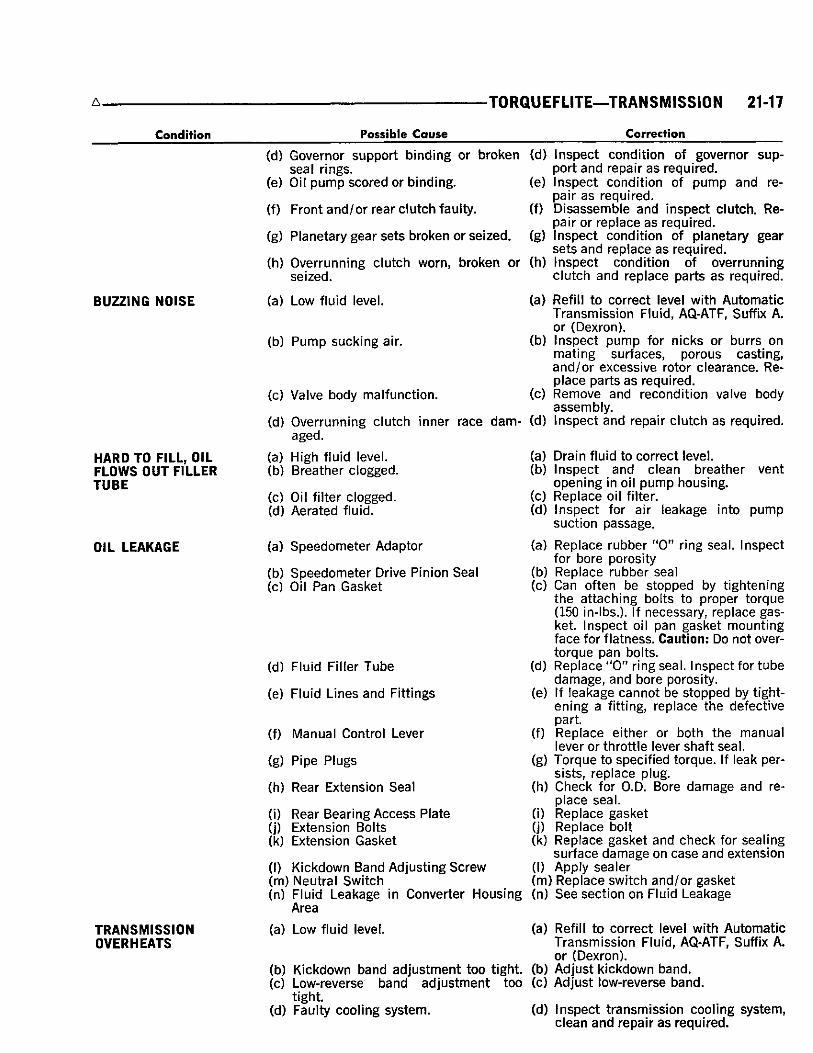
BUZZING N O I S E
HARD TO F I L L , O IL F L O W S OUT F I L L E R T U B E
OIL L E A K A G E
T R A N S M I S S I O N O V E R H E A T S
(d) Governor support binding or broken seal rings.
(e) Oil pump scored or binding.
(f) Front and /or rear clutch faulty.
(g) Planetary gear sets broken or se ized .
(h) Overrunning clutch worn, broken or se ized.
(a) Low fluid level.
(b) Pump sucking air.
(c) Valve body malfunction.
(d) Overrunning clutch inner race damaged.
(a) High fluid level. (b) Breather clogged.
(c) Oil filter clogged. (d) Aerated fluid.
(a) Speedometer Adaptor
(b) Speedometer Drive Pinion Sea l (c) Oil Pan Gasket
(d)
(e)
(f)
(g)
•(h)
sup-
re-
Inspect condition of governor port and repair a s required. Inspect condition of pump and pair a s required. D isassemble and inspect c lutch. Re pair or replace a s required. Inspect condition of planetary gear se ts and replace a s required. Inspect condition of overrunning clutch and replace parts a s required.
(a) Refill to correct level with Automatic Transmiss ion Fluid, AQ-ATF, Suffix A. or (Dexron).
(b) Inspect pump for n icks or burrs on mating sur faces, porous cast ing, and /o r excessive rotor c learance. Replace parts a s required.
(c) Remove and recondition valve body assembly .
(d) Inspect and repair c lutch a s required.
(a) (b)
(c) (d)
(a)
Drain fluid to correct level. Inspect and c lean breather vent opening in oil pump housing. Replace oil filter. Inspect for air leakage into pump suction passage.
(d) Fluid Fil ler Tube
(e) Fluid L ines and Fittings
(f) Manual Control Lever
(g) Pipe Plugs
(h) Rear Extension Seal
(i) Rear Bearing A c c e s s Plate (j) Extension Bolts (k) Extension Gasket
(I) Kickdown Band Adjusting Screw (m) Neutral Switch (n) Fluid Leakage in Converter Housing
Area
(a) Low fluid level.
(b) Kickdown band adjustment too t ight (c) Low-reverse band adjustment too (c) Adjust low-reverse band
t ight (d) Faulty cooling system.
Replace rubber " 0 " ring seal . Inspect for bore porosity
(b) Replace rubber seal (c) Can often be stopped by tightening
the attaching bolts to proper torque (150 in-lbs.). If necessary, replace gasket. Inspect oil pan gasket mounting face for f latness. Caution: Do not over-torque pan bolts. Replace "0" ring sea l . Inspect for tube damage, and bore porosity. If leakage cannot be stopped by tightening a fitting, replace the defective part. Replace either or both the manual lever or throttle lever shaft sea l ,
(g) Torque to specif ied torque. If leak pers is ts , replace plug. Check for O.D. Bore damage and replace sea l . Replace gasket Replace bolt Replace gasket and c h e c k for seal ing surface damage on c a s e and extension Apply sealer
(m) Replace switch and/or gasket (n) S e e section on Fluid Leakage
(d)
(e)
(f)
.(h)
(i) (j) (k)
(I)
(a) Refill to correct level with Automatic Transmiss ion Fluid, AQ-ATF, Suffix A. or (Dexron).
(b) Adjust kickdown band.
(d) Inspect t ransmission cooling system, c lean and repair a s required.

21-18 TRANSMISSION—TORQUEFLITE
Condition Possible Cause Correction
S T A R T E R W I L L NOT ENERGIZE IN NEUTRAL OR PARK
(e) Cracked or restricted oil cooler line or fitting.
(f) Faulty oil pump.
(g) Insufficient c lutch plate c learance in front and /o r rear c lu tches .
(a) Incorrect gearshift control linkage adjustment.
(b) Faulty or incorrectly adjusted neutral starting switch.
(c) Broken lead to neutral switch.
(e) Inspect, repair or replace a s required.
(f) Inspect pump for incorrect c learance, repair a s required.
(g) Measure clutch plate c learance and correct with proper s ize snap ring.
(a) Adjust control linkage.
(b) Tes t operation of switch with a test lamp. Adjust or replace a s required.
(c) Inspect lead and test with a test lamp. Repair broken lead.
STALL TEST
W A R N I N G : D U R I N G T E S T L E T N O O N E S T A N D IN F R O N T OF V E H I C L E .
T h e stal l test consists of determining the engine speed obtained at fu l l throttle in D position. T h i s test checks the torque converter stator c lutch operation, and the holding abil ity of the transmission c lutches. T h e t ransmission oil level should be checked and the engine brought to normal operating temperature before sta l l operation. Both the parking and service brakes must be fully applied and front wheels blocked while making this test.
Do not hold the throttle open any longer than is necessary to obtain a m a x i m u m engine speed reading, and never longer than five seconds at a time. I f more than one stal l check is requi red , operate the engine at approximately 1,000 r p m in neutra l for 20 seconds to cool the t ransmiss ion fluid between runs. I f engine speed exceeds the m a x i m u m l imits shown, re lease the accelerator immediate ly s ince t ransmission c lutch sl ippage is indicated.
STALL SPEED ABOWE SPECIFICATION
I f sta l l speed exceeds the m a x i m u m specif ied in chart by more than 200 r p m , t ransmission c lutch sl ippage is indicated. Fo l low the t ransmiss ion oil pressure and air pressure checks outl ined in the Serv ice on V e h i c l e section to determine the cause of sl ippage.
STALL SPEED BELOW SPECIFICATION
L o w sta l l speeds with a properly tuned engine indi
cate torque converter stator c lutch problems. A road test wi l l be necessary to identify the exact problem.
I f stal l speeds are 250-350 r p m below specification, and the vehicle operates properly at highway speeds, but has poor through-gear accelerat ion, the stator overrunning c lutch is sl ipping.
I f stal l speed and accelerat ion are normal , but abnormal ly high throttle opening is required to maintain highway speeds, the stator c lutch has seized.
Both of these stator defects require replacement of the torque converter.
NOISE
A whin ing or siren- l ike noise due to fluid flow is normal dur ing stal l operation wi th some converters; however, loud metal l ic noises f rom loose parts or inter ference within the assembly indicate a defective torque converter . T o confirm that the noise originates within the converter , operate the vehicle at light throttle in D and N on a hoist and l isten under the transmission bel l housing.
STALL SPEED SPECIFICATION CHART
Engine Model (C.I.D.).
Transmission Type
Engine Speed (RPM)
383-2 BBL . 383-4 B B L 440-4 BBL .
A727 A727 A727
1850-2100 2350-2650 2000-2300
SERVICE PROCEDURES
SERVICE IN VEHICLE V a r i o u s t ransmiss ion components can be removed
for repa i rs without removing the t ransmiss ion f r o m vehic le . T h e remova l , recondit ioning and instal lat ion procedures for these components are covered here , except va lve body recondit ioning, wh ich is descr ibed on Page 34.
ALUMINUM THREAD REPAIR
Damaged or worn threads in the a luminum transmiss ion case and valve body can be repai red by the use of Hel i -Coi ls . Essent ia l ly , this repa i r consists of dr i l l ing out the worn or damaged threads, tapping the hole with a specia l Hel i -Coi l T a p , and instal l ing a Hel i -Coi l Inser t into the tapped hole. T h i s br ings the
TORQUEFLITE—TRANSMISSION 21-19
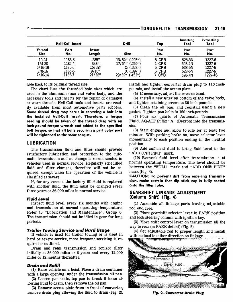
Inserting Extracting Heli-Coil Insert Drill Tap Tool Tool
Thread Part Insert Part Part Part Size No. Length Size No. No. No.
10-24 1185-3 .285" 13/64" (.203") 3 C P B 528-3N 1227-6 1/4-20 1185-4 3 /8" 17/64" (.265") 4 C P B 528-4N 1227-6
5/16-18 1185-5 15/32" Q (.332") 5 C P B 528-5N 1227-6 3/8-16 1185-6 9 /16" X (.397") 6 C P B 528-6N 1227-6
7/16-14 1185-7 21/32" 29 /32" (.453") 7 C P B 528-7N 1227-16
hole back to its or iginal thread size. T h e chart l ists the threaded hole sizes which are
used in the a luminum case and valve body, and the necessary tools and inserts for the repai r of damaged or worn threads. He l i -Coi l tools and inserts are readi ly available f rom most automotive parts jobbers. Some thread drag may occur in screwing a bolt into the installed Heli-Coil insert. Therefore, a torque reading should be taken of the thread drag with an inch-pound torque wrench and added to the specified bolt torque, so that all bolts securing a particular part will be tightened to the same torque.
LUBRICATION
T h e t ransmission fluid and filter should provide satisfactory lubr icat ion and protection to the automatic t ransmission and no change is recommended in vehicles used in normal serv ice. Regu lar ly scheduled fluid and filter changes, therefore wi l l not be required, except w h e n the operation of the vehic le is classified as severe.
If, for any reason, the factory fill fluid is rep laced wi th another fluid, the fluid must be changed every three years or 36,000 mi les in norma l service.
Flu id Level Inspect fluid level every s ix months with engine
and t ransmission at normal operat ing temperature. R e f e r to "Lubr ica t ion and Maintenance", Group 0. T h e t ransmission should not be idled in gear for long periods.
Trailer Towing Service and Hard Usage I f vehicle is used for t ra i ler towing or is used i n
hard or severe serv ice , more f requent serv ic ing is required as outl ined.
D r a i n and ref i l l t ransmission and replace filter init ial ly at 36,000 mi les or 3 years and every 12,000 mi les or 12 months thereafter.
Drain and Refill (1) Ra ise vehic le on a hoist. P lace a dra in container
wi th a large opening, under the t ransmission oi l pan . (2) Loosen pan bolts, tap pan to break it loose al
lowing fluid to dra in , then remove the oil pan. (3) Remove access plate f rom in front of converter ,
remove dra in p lug al lowing the fluid to dra in (F ig . 2).
Insta l l and tighten converter dra in p lug to 110 inch-pounds, and insta l l the access plate.
(4) I f necessary , adjust the reverse band. (5) Insta l l a n e w filter on bottom of the va lve body,
and t ighten reta in ing screws to 35 inch-pounds. (6) C l e a n the oil pan , and re insta l l us ing a new
gasket. T ighten pan bolts to 150 inch-pounds. (7) P o u r six quarts of Automat ic T r a n s m i s s i o n
F l u i d , A Q - A T F Suffix " A " (Dexron) into the t ransmission.
(8) Star t engine and allow to idle for at least two minutes . W i t h park ing brake on, move selector lever momentar i ly to each position ending i n the neut ra l posit ion.
(9) A d d sufficient fluid to br ing fluid leve l to the " A D D O N E P I N T " mark .
(10) R e c h e c k fluid leve l after t ransmission is at norma l operat ing temperature. T h e leve l should be between the " F U L L " m a r k and " A D D O N E P I N T " m a r k (Fig. 3). CAUTION: To prevent dirt from entering transmission, make certain that dip stick cap is fully seated onto the filler tube.
GEARSHIFT LINKAGE ADJUSTMENT (Column Shift) (Fig. 4)
(1) Assemble al l l inkage parts leaving adjustable rod end free.
(2) P lace gearshift selector lever in P A R K position and lock steer ing co lumn wi th ignit ion key.
(3) Move shift control lever on t ransmission a l l the way to rear (in P A R K detent) (Fig. 5).
(4) Set adjustable rod to proper length and instal l wi th no load in ei ther direction on l inkage.
Fig. 2—Converter Drain Mug

21-20 TRANSMISSION—TORQUEFLITE
ND167A
Fig. 3—Dip Stick Markings
(5) C h e c k A d j u s t m e n t as follows: (a) Shif t effort must be free and detents feel
cr isp . A l l gate stops must be positive. (b) Detent position must be close enough to gate
stops in neutra l and dr ive to assure that hand lever w i l l not rema in out of detent position when placed against gate and then re leased.
(c) K e y start must occur with shift lever he ld down against the park gate.
LINKAGE ADJUSTMENT (Console Shift) (Fig. 8)
(1) Assemble a l l l inkage parts leaving adjustable rod ends free.
(2) A t steer ing co lumn upper end, l ine up locat ing slots in bottom of shift housing and bear ing housing. Insta l l suitable tool to hold this al ignment and lock co lumn with ignit ion key.
(3) P lace console lever in P A R K and move shift control lever on t ransmission al l the way to the r e a r (in P A R K detent).
(4) Set adjustable rods to proper length wi th no load applied in e i ther direct ion on l inkage.
PY228
A
Fig. 5—External Controls and Mdimtments
(5) C h e c k adjustment as follows: (a) Shif t effort should be f ree enough so detents
feel cr isp . (b) Detent position must be close enough to gate
stops in neut ra l and dr ive to assure that hand lever w i l l not rema in out of detent position when placed against gate and then re leased.
(c) K e y start and locking must occur with shift l eve r he ld back against the park gate.
(6) I f console removal is requi red, disconnect battery ground cable. Remove set screw and shift knob or handle. P roceed as outl ined in Body Sect ion 23.
(7) A f te r console is in place, instal l shift knob as follows: wi th gearship lever h i N E U T R A L , thread button, spr ing and knob assembly on the cable end unt i l d imension f rom top of button to top of knob is 1 3 / 3 2 " (F ig . 6). Secure knob wi th set screw.
(8) Connect battery ground cable.
Fig. 4—Gearshift Linkage Fig. 6—Console Gearshift Unit

A, TORQUEFLITE—TRANSMISSION 21-21
SCREWS (2)
SCREWS (4)
CONTACT
SEAL
WIRING CONNECTOR SWITCH
NU450
NN564C
Fig. 7—Removing or Installing Console
BACK-UP LIGHT AND NEUTRAL STARTING SWITCH (Fig. 9 and 10)
R e p l a c e m e n t a n d Tes t T h e Neutral Start ing Switch is the center te rmina l
of the 3 termina l switch. I t provides ground for the starter solenoid c ircui t through the selector lever
STEERING COLUMN
Fig. 9—Nevtral-Park Starting Switch and Back-Up Light Switch
c a m in only Park and Neutral positions. (1) T o test swi tch, remove w i r i n g connector f rom
switch and test for continuity between center p in of swi tch and transmission case. Cont inui ty should exist only when t ransmission is in Park or Neutral.
(2) C h e c k gearshif t l inkage adjustment before replacing a swi tch w h i c h tests bad.
(3) U n s c r e w swi tch f rom t ransmiss ion case al lowing fluid to dra in into a container. Move selector lever to Park and then to Neutral positions, and inspect to see that the swi tch operating lever fingers are centered in swi tch opening in the case.
(4) S c r e w swi tch and new sea l into t ransmission case and tighten to 24 foot-pounds. Retest swi tch wi th the test lamp.
LOWER ROD
Fig* i—Console Gearshift Linkage
PY231

21-22 TRANSMISSION—TORQUEFLITE •A
Fig. I©—Bottom View of Transmission (Pan Removed)
(5) A d d fluid to t ransmission to br ing up to proper level .
(6) T h e Back -Up Light Swi tch C i rcu i t is through the two outside terminals of the 3 te rmina l swi tch .
(7) T o test swi tch, remove wi r ing connector f rom switch and test for continuity between the two outside pins.
(8) Continuity should exist only wi th t ransmission in Reverse position.
(9) No continuity should exist f rom either p in to the case.
BAND ADJUSTMENTS
Kickdown Band T h e k ickdown band adjust ing screw is located on
left side of t ransmission case near the throttle lever shaft (F ig. 5).
(1) L o o s e n lock nut and back off approximately five turns. Inspect adjust ing s c r e w for f ree turn ing in the t ransmission case.
(2) U s i n g w r e n c h , Too l C-3380 wi th adapter C-3705, t ighten band adjust ing sc rew 47 to 50 inch-pounds. I f adapter C-3705 is not used , t ighten adjust ing sc rew to 72 inch-pounds w h i c h is the t rue torque.
(3) B a c k off adjust ing s c r e w 2 turns . Ho ld adjusting screw i n this position and t ighten lock nut to 29 foot-pounds.
Low and Reverse Band (1) Ra ise vehic le , dra in t ransmiss ion fluid and re
move oil pan. (2) L o o s e n adjust ing s c r e w lock nut and back off
nut approximately five tu rns (F ig . 10). Inspect adjusting screw for f ree turn ing i n the lever .
(3) U s i n g w r e n c h , Too l C-3380 wi th adapter C-3705, t ighten band adjust ing s c r e w to 47 to 50 inch-pounds.
I f adapter C-3705 is not used , t ighten adjust ing screw to 72 inch-pounds.
(4) B a c k off adjust ing sc rew 2 turns. Ho ld adjusting screw in this position and tighten lock nut to 35 foot-pounds.
(5) Re insta l l oi l pan us ing a new gasket. T ighten oil pan bolts to 150 inch-pounds.
(6) F i l l t ransmission wi th "Automat ic T ransmiss ion F l u i d A Q - A T F Suffix A , (Dexron).
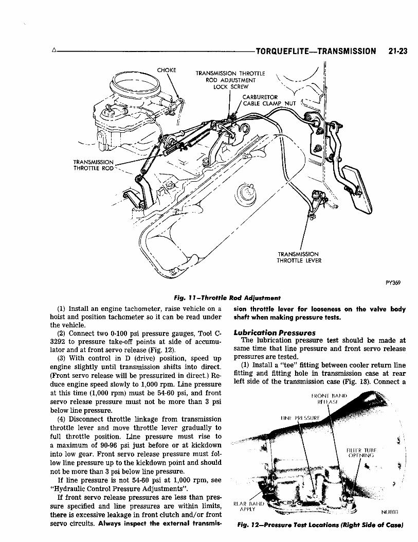
THOTTLE ROD ADJUSTMENT (Fig. 11)
With engine at operating temperature and carburetor off fast idle cam, adjust idle speed of engine us ing a tachometer. R e f e r to " F u e l S y s t e m " Group 14, for idle speed Specifications and carburetor l inkage adjustment.
(1) Fo l low detai led instruct ions in Lubr icat ion Section for l inkage lubricat ion of a l l models.
(2) Disconnect choke at carburetor or block choke valve in fu l l open position. Open throttle slightly to release fast idle cam, then re turn carburetor to curb idle.
(3) Loosen the transmission throttle rod adjustment lock screw.
(4) Hold the t ransmission lever forward against its stop whi le adjust ing the transmission l inkage. (On engines with solenoid idle stops, the solenoid plunger must also be in its ful ly extended position).
(5) A d j u s t the transmission rod by pul l ing forward on the slotted l ink with a slight effort so that the rear edge of the slot is against the carburetor lever pin. T ighten t ransmission rod adjustment locking screw.
Note: T h e slotted l ink and transmission lever must be held forward whi le the locking screw is being tightened.
(6) T o check t ransmission l inkage freedom of operation, move slotted l ink to the ful l rearward position, then allow it to re turn slowly, making sure it re turns to the fu l l forward position.
(7) Loosen carburetor cable c lamp nut. A d j u s t position of cable housing ferru le in the clamp so that a l l s lack is removed f rom cable with carburetor at curb idle. To remove s lack f rom cable, move ferru le in the clamp in direction away f rom carburetor lever .
(8) B a c k off ferru le 1/4". T h i s provides 1 / 4" free play. T ighten cable c lamp nut to 45 inch-pounds.
(9) Connect choke rod or remove blocking fixture.
HYDRAULIC CONTROL P R E S S U R E T E S T S
Line Pressure and Front Servo Release Pressure
L i n e pressure and front servo re lease pressure tests must be made in D (drive) posit ion with r e a r wheels f ree to turn. T h e t ransmiss ion fluid must be at operating temperature ( 1 5 0 ° F to 2 0 0 ° F ) .
A . TORQUEFLITE—TRANSMISSION 21-23
Fig. I I -Thrott le
(1) Insta l l an engine tachometer, ra ise vehicle on a hoist and position tachometer so it c a n be read under the vehicle.
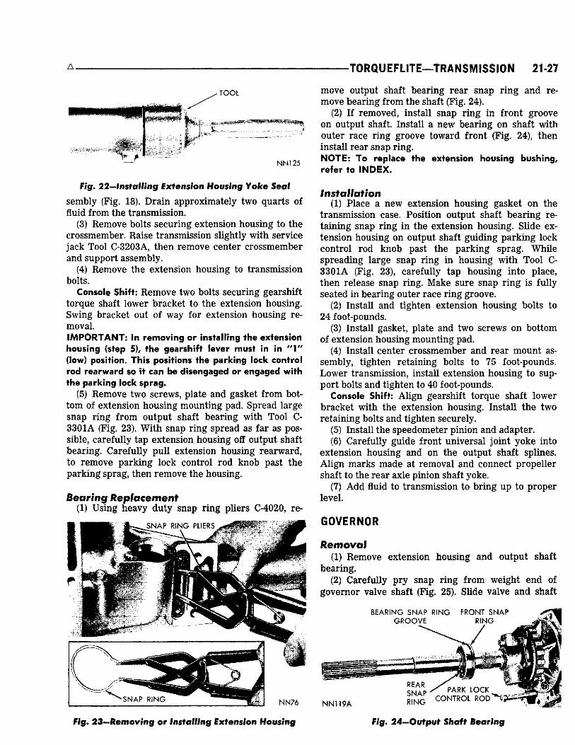
(2) Connect two 0-100 ps i p ressure gauges, Too l C -3292 to pressure take-off points at s ide of accumulator and at front servo re lease (Fig. 12).
(3) Wi th control in D (drive) posit ion, speed up engine sl ightly unt i l t ransmission shifts into direct. (Front servo release wi l l be pressur ized in direct.) Re duce engine speed slowly to 1,000 r p m . L i n e pressure at this t ime (1,000 rpm) must be 54-60 ps i , and front servo re lease pressure must not be more than 3 psi below l ine pressure .
(4) Disconnect throttle l inkage f r o m t ransmission throttle lever and move throttle lever gradual ly to fu l l throttle position. L i n e pressure must r ise to a m a x i m u m of 90-96 ps i jus t before or at k ickdown into low gear. F r o n t servo re lease pressure must follow l ine pressure up to the k ickdown point and should not be more than 3 psi below l ine pressure .
I f l ine pressure is not 54-60 psi at 1,000 r p m , see "Hydrau l ic Contro l P r e s s u r e Ad jus tments" .
I f front servo re lease pressures are less than pressure specified and l ine pressures are wi th in l imits, there is excessive leakage i n front c lu tch a n d / o r front servo c ircui ts . Always inspect the external transmis-
Rod Adjustment
sion throttle lever for looseness on the valve body shaft when making pressure tests.
Lubrication Pressures T h e lubr icat ion p ressure test should be made at
same t ime that l ine p ressure and front servo re lease pressures are tested.
(1) Insta l l a " tee" fitting between cooler r e t u r n l ine fitting and fitting hole i n t ransmiss ion case at r e a r left side of the t ransmiss ion case (F ig . 13). Connect a
Fig. 12—Pressure Test Locations (Right Side of Case)

21-24 TRANSMISSION—TORQUEFLITE-
0-100 ps i pressure gauge, Too l C-3292 to the " tee" fitting.
(2) A t 1,000 engine r p m , wi th throttle c losed and t ransmiss ion in direct, the lubricat ion pressure should be 5-15 psi . Lubr ica t ion pressure wi l l be approximately doubled as throttle is opened to the m a x i m u m l ine pressure .
Throttle Pressure No provisions a re made to test the throttle pressure .
Incorrect throttle pressure should only be suspected if part throttle shift speeds are ei ther very delayed or occur too ear ly in relat ion to vehicle speeds. I n wh ich case, the throttle l inkage should be adjusted before throttle pressure setting is adjusted.
R e a r S e r v o Apply Pressure (1) Connect a 0-300 ps i pressure gauge, T o o l C-3293
to apply pressure take-off point at r e a r servo (F ig . 13). (2) W i th t ransmission control in R (reverse) posi
t ion and engine speed set at 1600 r p m , the reverse servo apply pressure should be 230 to 300 psi .
G o v e r n o r Pressure (1) Connect a 0-100 psi pressure gauge, Too l C-3292
to governor pressure take-off point, located at lower left side of extension near the mount ing flange (Fig. 13).
(2) Governor pressures should fal l wi th in the l imits given in the "Governor P r e s s u r e C h a r t . "
I f governor pressures are incorrect at the given vehic le speeds, the governor valve a n d / o r weights are probably st icking.
GOVERNOR PRESSURE CHART
Vehicle Speed To Axle Ratios Pressure Chrysler Imperial Limits*
2.76:1 3.23:1 2.94:1 psi
20-22 17-19 19-22 15 48-57 41-49 48-57 50 77-85 66-73 77-85 75
* T h e governor pressure should respond smoothly to changes in m.p.h. and should return to 0 to 1-1/2 psi when the vehicle is stopped. High pressure at standstill (above 2 psi) will prevent the t ransmission from downshifting.
LUBRICATION PRESSURE
(COOLER RETURN FITTING)
GOVERNOR PRESSURE
REAR SERVO APPLY
PRESSURE
HYDRAULIC CONTROL P R E S S U R E ADJUSTMENTS
Line Pressure A n incorrect throttle pressure sett ing wi l l cause in
correct l ine pressure readings even though l ine pressure adjustment is correct . A l w a y s inspect and correct throttle pressure adjustment before adjust ing the l ine pressure . Before adjusting line pressure, measure distance between the manual valve (valve in 1-low position) and line pressure adjusting screw (Fig. 14). This measurement must be 1-7/8 inches; correct by loosening spring retainer screws and repositioning the spring retainer. The regulator valve may cock and hang up in its bore if spring retainer is out of position.
I f l ine pressure is not correct , it w i l l be necessary to remove valve body assembly to per form the adjustment .
T h e approximate adjustment is 1-5/16 inches, measured f rom valve body to inner edge of the adjusting nut (Fig. 15). However , due to manufactur ing tolerances, the adjustment can be var ied to obtain specified l ine pressure .
T h e adjust ing screw may be turned wi th an A l l e n wrench . One complete tu rn of adjust ing s c r e w changes closed throttle l ine pressure approximately 1-2/3 psi . T u r n i n g adjust ing s c r e w counterclockwise increases pressure , and clockwise decreases pressure .
Throttle Pressure Thrott le pressure cannot be tested accurately:
NN71A
Fig. 13—Pressure Test Locations (Rear End of Case) Fig. 14—Measuring Spring Retainer Location

-TORQUEFLITE—TRANSMISSION 21-25
SB
NN72A
Fig. 15—Lira© iprcssswr® Adjustment
therefore, the adjustment should be measured if a malfunct ion is evident.
(1) Remove valve body assembly f rom transmission to per form adjustment .
(2) Loosen throttle lever stop screw lock nut and back off approximately five tu rns (F ig . 16).
(3) Insert gauge p in of Too l C-3763 between the throttle lever cam and k ickdown valve.
(4) B y pushing in on the tool, compress k ickdown valve against its spr ing so throttle va lve is completely bottomed inside the valve body.
(5) A s force is being exer ted to compress spr ing, t ighten throttle lever stop s c r e w finger tight against throttle lever tang wi th throttle lever cam touching the tool and the throttle valve bottomed. Be sure adjustment is made with spring fully compressed and valve bottomed in the valve body.
(6) Remove tool and tighten stop screw lock nut securely .
AIR P R E S S U R E T E S T S
A "NO D R I V E " condit ion might exist even with
/ ^ T O O L
K I C K D O W N \ - V A L V E
L O C K N U T
THROTTLE LEVER
S T O P S C R E W
NN73A
correct fluid pressure , because of inoperat ive c lu tches or bands. T h e inoperat ive units, c lutches, bands and servos c a n be located through a ser ies of tests by substi tut ing a ir pressure for fluid pressure (F ig . 17). T h e f ront and r e a r c lutches, k ickdown servo, and low-reverse servo may be tested by apply ing a i r pressure to their respect ive passage after valve body assembly has been removed. T o make a i r p ressure tests, proceed as fol lows: CAUTION: Compressed air supply must be free of all dirt or moisture. Use a pressure of 30 to 100 psi.
Front Clutch A p p l y a i r pressure to front c lu tch "apply" passage
and l is ten for a dul l " thud" which indicates that r e a r c lu tch is operating. Hold air pressure on for a few seconds and inspect system for excessive oil leaks.
Rear Clutch A p p l y a i r pressure to rear c lutch "apply" passage
and l is ten for a dul l " t h u d " wh ich indicates that r e a r c lu tch is operat ing. A lso check for excessive oil l eaks .
If a dull "thud" cannot be heard in clutches, place finger tips on clutch housing and again apply air pressure. Movement of piston can be felt as clutch is applied.
Kickdown Servo Direc t a i r pressure into front servo "apply" pas
sage. Operat ion of servo is indicated by a t ightening of the front band. Spr ing tension on servo piston should re lease the band.
LINE PRESSURE T O A C C U M U L A T O R ^ ^ ^ , F R ? N T S E R ^ °
FRONT SERVO RELEASE
• | PUMP
< A U C T I O N
: f - 1 -. P U M P
P R E S S U R E
I' F R O N T CLUTCH
' APPLY
* PEAR CLUTCH J A P P L Y
' J TO T O R Q U E C O N V E R T E R • • • • •
F R O M T O R Q U E C O N V E R T E R
ND8A W T O COOLER -><
£'%0 ITftreffffi/© \Pv®mure Adjustment Fig. 17—Air Pressure Tests

21-26 TRANSMISSION—TORQUEFLITE .A
Low and Reverse Servo Direct air pressure into servo "apply" passage.
Operat ion of servo is indicated by a t ightening of the r e a r band. Spr ing tension on servo piston should release the band.
I f c lutches and servos operate properly; no upshif t or errat ic shift condit ions indicate that malfunct ion exists in the valve body.
SPEEDOMETER PINION
Removal and Installation R e a r axle gear ratio and t ire size determines pinion
gear size requirements . R e f e r to 'Speedometer P in ion Char t ' in Specif ications for pinion usage.
(1) Remove bolt and reta iner secur ing speedometer pinion adapter in the extension housing (F ig . 18).
(2) W i th cable housing connected, carefu l ly work adapter and pinion out of the extension housing.
(3) I f t ransmiss ion fluid is found i n cable housing, replace sea l i n the adapter (F ig. 19). Start sea l and reta iner r ing in the adapter, then push them into adapter wi th Too l C-4004 unt i l tool bottoms (Fig. 20). CAUTION: Before installing pinion and adapter assembly make sure adapter flange and its mating area on extension housing are perfectly clean. Dirt or sand will cause mis-alignment resulting in speedometer pinion gear noise.
(4) Note n u m b e r of gear teeth and instal l speedometer pinion gear into adapter (Fig. 19).
(5) Rotate the speedometer pinion gear and adapter assembly so that the n u m b e r on the adapter, corresponding to the number of teeth on the gear, is in the 6 o'clock position as the assembly is instal led (Fig. 18).
(6) Insta l l reta iner and bolt, wi th reta iner tangs i n adapter posit ioning slots. T a p adapter firmly into the extension housing and tighten reta iner bolt to 100 inch-pounds.
EXTENSION HOUSING YOKE SEAL
Replacement (1) Mark parts for reassembly then disconnect pro
pel ler shaft at r e a r un iversa l joint. Care fu l ly pul l shaft
• RETAINER
ADAPTER
- 6 O'CLOCK POSITION NN74A
Fig. I8—Speedometer Pinion and Adapter-Installed (Retainer Removed for View)
BOLT AND WASHER
ADAPTER
RING
PINION
OIL SEAL
RETAINER RING
NN362
Fig. 19—Speedometer Drive
yoke out of t ransmission extension housing. CAUTION: Be careful not to scratch or nick ground surface on sliding spline yoke during removal and installation of the shaft assembly.
(2) Remove the extension housing yoke sea l (F ig . 21) wi th Too l C-3985.
(3) T o insta l l a new seal , position s e a l i n opening of extension housing and dr ive it into housing wi th Too l C-3972 (Fig. 22).
(4) Care fu l ly guide front un iversa l joint yoke into extension housing and on the output shaft spl ines. A l i g n m a r k s made at removal and connect propel ler shaft to rear axle pinion shaft yoke.
EXTENSION HOUSING AND OUTPUT SHAFT BEARING
Removal (1) Mark parts for reassembly then disconnect pro
pel ler shaft at rea r un iversa l joint. Care fu l ly pul l shaft assembly out of the extension housing.
(2) Remove speedometer pinion and adapter as-ADAPTER LOCK RING
TOOL SEAL
NP2
H
Fig. 20—Installing Speedometer Pinion Seal
TOOL
\ SEAL
NN36J
Fig. 21—Removing Extension Housing Yoke Seal
A . -TORQUEFLITE—TRANSMISSION 21-27
'TOOL
•*8$jr • • r * £ ? " -*S0">- • •
— NN125
Fig. 22—installing Extension Housing Yoke Semi
sembly (Fig. 18). D r a i n approximately two quarts of fluid f rom the t ransmiss ion.
(3) Remove bolts secur ing extension housing to the crossmember. Ra ise t ransmiss ion slightly wi th serv ice j a c k Tool C-3203A, then remove center c rossmember and support assembly.
(4) Remove the extension housing to t ransmission bolts.
Console Shift : R e m o v e two bolts secur ing gearshif t torque shaft lower bracket to the extension housing. Swing bracket out of way for extension housing removal . I M P O R T A N T : In removing or instal l ing the extension housing (step 5), the gearshift lever must in in "V (low) position. T h i s positions the parking lock control rod rearward so it can be disengaged or engaged with the parking lock sprag .
(5) Remove two screws , plate and gasket f rom bottom of extension housing mount ing pad. Spread large snap r ing f rom output shaft bear ing wi th Too l C -3301A (Fig. 23). W i t h snap r ing spread as fa r as possible, carefu l ly tap extension housing off output shaft bear ing. Care fu l ly pu l l extension housing rearward , to remove park ing lock control rod knob past the park ing sprag, then remove the housing.
Bearing Replacement (1) U s i n g heavy duty snap r ing pl iers C-4020, re-
•w SNAP RING PLIERS 111
move output shaft bear ing r e a r snap r ing and remove bear ing f rom the shaft (F ig . 24).
(2) I f removed, instal l snap r ing in f ront groove on output shaft. Insta l l a new bear ing on shaft with outer race r ing groove toward front (F ig . 24), then insta l l rear snap r ing . N O T E : T o replace the extension housing bushing, refer to I N D E X .
Installation (1) P lace a new extension housing gasket on the
t ransmiss ion case. Posit ion output shaft bear ing reta in ing snap r ing i n the extension housing. Sl ide extension housing on output shaft guiding park ing lock control rod knob past the park ing sprag. Wh i le spreading large snap r ing in housing wi th Too l C -3 3 0 1 A (Fig. 23), carefu l ly tap housing into place, then release snap r ing. Make sure snap r ing is ful ly seated in bear ing outer race r ing groove.
(2) Insta l l and tighten extension housing bolts to 24 foot-pounds.
(3) Instal l gasket, plate and two screws on bottom of extension housing mounting pad.
(4) Instal l center c rossmember and r e a r mount assembly, t ighten reta ining bolts to 75 foot-pounds. L o w e r t ransmission, instal l extension housing to support bolts and tighten to 40 foot-pounds.
Console Shift: A l i g n gearshift torque shaft lower bracket wi th the extension housing. Insta l l the two reta in ing bolts and tighten securely .
(5) Instal l the speedometer pinion and adapter. (6) Care fu l ly guide front un iversa l joint yoke into
extension housing and on the output shaft spl ines. A l i g n marks made at removal and connect propel ler shaft to the rear axle pinion shaft yoke.
(7) A d d fluid to t ransmission to br ing up to proper level .
GOVERNOR
Removal (1) Remove extension housing and output shaft
bear ing. (2) Care fu l ly pry snap r ing f rom weight end of
governor valve shaft (F ig. 25). S l ide valve and shaft
BEARING SNAP RING FRONT SNAP * A
GROOVE RING
NN76 NN119A
REAR SNAP RING CONTROL ROD
Fig. 23—Removing or Installing Extension Housing Fig. 24—Output Shaft Bearing

21-28 ISSION—TORQUEFLITE-
G O V E R N O R SUPPORT A r D P A R K I N G G E A R
SNAP RING
• GOVERNOR B O D Y
• BOLTS 14)
LOC< STRAPS N N 7 7
i?actio Governor Shaft and Weight Snap Rings
assembly out of the governor body. (3) Remove large snap r ing f rom weight end of
governor body, lift out governor weight assembly. (4) Remove snap r ing f rom inside governor weight,
remove inner weight and spr ing f rom outer weight. F i g u r e 26 shows a d isassembled v iew of the governor assembly.
(5) Remove snap r ing f rom behind governor body, then slide body and support assembly off the output shaft. I f necessary , remove four bolts and separate governor f rom the support .
Cleaning and Inspection T h e pr imary cause of governor operat ing fa i lure is
due to a st icking governor valve or weights. R o u g h sur faces may be removed wi th crocus cloth. Thor oughly c lean a l l parts i n c lean solvent and inspect for free movement before assembly.
Installation (1) Assemble governor body to the support (if dis
assembled) and t ighten the bolts finger tight. Make sure oil passage of governor body al igns wi th passage in the support.
I S P R I N G
B O D Y
S N A P R I N G S
V A L V E SHAFT
I N N E R W E I G H T V A L V E
(2) Posit ion support and governor assembly on output shaft. A l ign assembly so governor valve shaft hole in governor body al igns wi th hole in the output shaft , then sl ide assembly into place. Insta l l snap r ing behind governor body (Fig. 25). T ighten body to support bolts to 100 inch-pounds. B e n d ends of lock straps over the bolt heads.
(3) Assemble governor weights and spr ing, and secure wi th snap r ing inside large governor weight. P lace weight assembly in governor body and instal l snap r ing.
(4) P lace governor valve on valve shaft, insert the assembly into body and through governor weights. Insta l l valve shaft re ta in ing snap r ing. Inspect valve and weight assembly for f ree movement after instal lation.
(5) Insta l l output shaft bear ing and extension housing.
PARKING LOCK COMPONENTS
Removal (1) Remove the extension housing. (2) T o replace the governor support and park ing
gear, re fer to "governor and support" . (3) Sl ide shaft out of extension housing to remove
the park ing sprag and spr ing (Fig. 27). Remove snap r ing and slide react ion plug and pin assembly out of +1no In n i l c l Y* rt
itkix* i i u moi.ii .
(4) T o replace the park ing lock control rod, re fer to " V a l v e B o d y — R e m o v a l and Instal lat ion."
Installation (1) Posit ion sprag and spr ing in housing and insert
the shaft (F ig. 27). Make sure square lug on sprag is toward the park ing gear, and spr ing is positioned so it moves sprag away f rom the gear.
(2) Insta l l react ion p lug and p in assembly in the housing and secure wi th snap r ing.
(3) Insta l l extension housing.
S N A P R I N G -
SPRING 'SNAP RING
PLUG AND PIN
CONTROL ROD
S P R I N G
NN78B
Fig. 26—Governor Assembly Fig. 27—Parking Lock Components
-TORQUEFLITE—TRANSMISSION 21-29
VALVE BODY ASSEMBLY AND ACCUMULATOR PISTON
Removal (1) Ra ise the vehicle on a hoist. (2) L o o s e n oil pan bolts, tap pan to b r e a k it loose
al lowing fluid to dra in , then remove the oi l pan . (3) D isconnect throttle and gearshift l inkage f rom
levers on the t ransmission. L o o s e n c lamp bolts and remove the levers (Fig. 5).
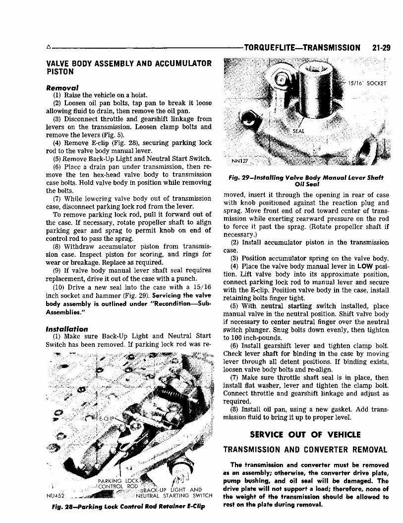
(4) Remove E-c l ip (Fig. 28), secur ing p a r k i n g lock rod to the valve body manua l lever .
(5) Remove B a c k - U p L igh t and Neut ra l Star t Swi tch . (6) P lace a drain pan under t ransmiss ion, then re
move the ten hex-head valve body to t ransmiss ion case bolts. Ho ld valve body in position w h i l e remov ing the bolts.
(7) Wh i le lower ing valve body out of t ransmiss ion case, disconnect park ing lock rod f rom the lever .
T o remove park ing lock rod, pu l l it fo rward out of the case. I f necessary , rotate propel ler shaft to al ign park ing gear and sprag to permit knob on end of control rod to pass the sprag.
(8) W i thdraw accumulator piston f rom transmission case. Inspect piston for scor ing, and r ings for wear or breakage. Replace as required.
(9) I f valve body manua l lever shaft sea l requires replacement , dr ive it out of the case with a p u n c h .
(10) Dr ive a new seal into the case w i th a 15 /16 inch socket and h a m m e r (Fig. 29). Servicing the valve body assembly is outlined under ''Recondition—Sub-Assemblies/'
Installation (1) Make sure Back -Up L i g h t and Neut ra l Start
Swi tch has been removed. I f park ing lock rod was re-
• 4 3
E C U ? -
4*
f l PARKING LOCK
:CONr-K>L R ° D BACK-UP LIGHT AND i NEUTRAL STARTING SWITCH
15/16 ' SOCKET
NN127
Fig. 28—Parking Lock Control Rod Retainer f-Cfip
Fig. 29—Installing Valve Body Manual Lever Shaft Oil Seal
moved, insert it through the opening in r e a r of case wi th knob positioned against the react ion plug and sprag. Move front end of rod toward center of transmission whi le exert ing r e a r w a r d pressure on the rod to force it past the sprag. (Rotate propel ler shaft if necessary. )
(2) Insta l l accumulator piston in the t ransmission case.
(3) Posit ion accumulator spr ing on the valve body. (4) P lace the valve body m a n u a l lever in LOW posi
tion. L i f t valve body into its approximate position, connect park ing lock rod to m a n u a l lever and secure wi th the E-cl ip . Posit ion valve body in the case, instal l re ta in ing bolts finger tight.
(5) W i t h neut ra l start ing swi tch instal led, place m a n u a l valve in the neut ra l position. Shif t valve body if necessary to center neut ra l f inger over the neutra l swi tch plunger. S n u g bolts down evenly, then tighten to 100 inch-pounds.
(6) Insta l l gearshif t lever and t ighten c lamp bolt. C h e c k lever shaft for b inding i n the case by moving lever through a l l detent positions. I f b inding exists, loosen valve body bolts and re-al ign.
(7) Make sure throttle shaft sea l is in place, then insta l l flat washer , lever and t ighten the c lamp bolt. Connect throttle and gearshift l inkage and adjust as requi red .
(8) Insta l l oi l pan , us ing a new gasket. A d d transmission fluid to b r ing it up to proper level .
SERVICE OUT OF VEHICLE
TRANSMISSION AND CONVERTER REMOVAL
The transmission and converter must be removed as an assembly; otherwise, the converter drive plate, pump bushing, and oil seal will be damaged. The drive plate will not support a load; therefore, none of the weight of the transmission should be allowed to rest on the plate during removal.
2 1 - 3 0 TRANSMISSION—TORQUEFLITE
(1) Connect a Remote Control Star ter Swi tch , Tool C-763 to starter solenoid and position swi tch so engine can be rotated f rom under the vehicle.
(2) Disconnect secondary (high tension) cable, f rom the ignition coil .
(3) Remove cover plate in front of converter to provide access to converter dra in p lug and mount ing bolts.
(4) Rotate engine with Remote Contro l Swi tch to br ing dra in plug to "6 o'clock " position. D r a i n torque converter and t ransmission.
(5) Mark converter and drive plate to aid in reassembly. T h e crankshaf t flange bolt c i rc le , inner and outer c i rc le of holes in drive plate, and four tapped holes in front face of converter a l l have one hole offset so these parts wi l l be instal led in original position. T h i s maintains balance of the engine and converter .
(6) Rotate engine wi th Remote Contro l Swi tch to locate two converter to drive plate bolts at "5 and 7 o'clock" positions. Remove the two bolts, rotate engine wi th switch and remove the other two bolts. Do not rotate converter or drive plate by prying with a screw driver or similar tool as the drive plate might become distorted. Also, starter should never be engaged if drive plate is not attached to converter with at least one bolt or if transmission case to engine block bolts have been loosened.
(7) Disconnect negative (ground) cable f rom battery.
(8) Remove the start ing motor assembly. (9) Disconnect w i re f rom the neutra l start ing
switch. (10) Disconnect gearshift rod f rom the t ransmis
sion lever. Remove gearshift torque shaft f rom transmission housing and left side ra i l .
Console Shift: Remove two bolts secur ing gearshif t torque shaft lower bracket to the extension housing. Swing bracket out of the way for t ransmiss ion removal . Disconnect gearshift rod f rom the t ransmission lever.
(11) Disconnect throttle rod f rom bel lcrank at left side of t ransmission bel l housing.
(12) Disconnect oil cooler l ines at t ransmiss ion and remove oil filler tube. Disconnect the speedometer cable.
(13) Mark parts for reassembly then disconnect propel ler shaft at rea r un iversa l joint. Care fu l ly pu l l shaft assembly out of the extension housing.
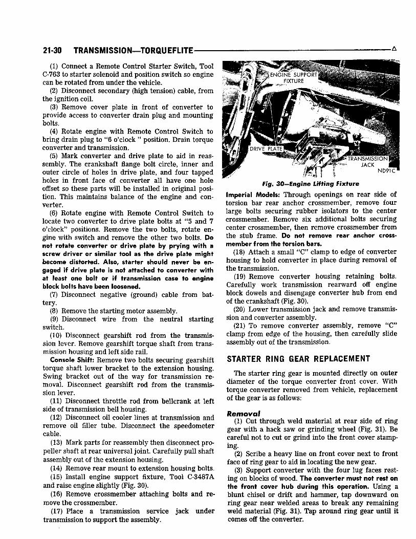
(14) Remove rear mount to extension housing bolts. (15) Insta l l engine support fixture, Too l C-3487A
and ra ise engine sl ightly (Fig. 30). (16) Remove crossmember attaching bolts and re
move the crossmember . (17) P lace a t ransmission serv ice j a c k u n d e r
t ransmiss ion to support the assembly.
A
Fig. 30—Engine Lifting Fixture
Imperial Models: T h r o u g h openings on rear side of torsion bar rea r anchor crossmember , remove four large bolts secur ing rubber isolators to the center crossmember . Remove six addit ional bolts secur ing center crossmember , then remove crossmember f rom the stub frame. Do not remove rear anchor cross-member from the torsion bars.
(18) At tach a smal l " C " c lamp to edge of converter housing to hold converter in place dur ing removal of the t ransmission.
(19) Remove conver ter housing reta ining bolts. Care fu l ly work t ransmiss ion rea rward off engine block dowels and disengage converter hub f rom end of the crankshaf t (F ig . 30).
(20) L o w e r t ransmission j a c k and remove t ransmission and converter assembly.
(21) T o remove conver ter assembly, remove " C " c lamp f rom edge of the housing, then careful ly sl ide assembly out of the t ransmission.
STARTER RING GEAR REPLACEMENT
T h e starter r ing gear is mounted direct ly on outer diameter of the torque converter front cover. Wi th torque converter removed f rom vehic le , replacement of the gear is as follows:
Removal (1) Cut through we ld mater ia l at r e a r side of r ing
gear wi th a hack saw or gr inding whee l (F ig. 31). B e care fu l not to cut or gr ind into the front cover stamping.
(2) Scr ibe a heavy l ine on front cover next to front face of r ing gear to aid in locating the new gear.
(3) Support converter wi th the four lug faces resting on blocks of wood. The converter must not rest on the front cover hub during this operation. U s i n g a blunt ch ise l or dri f t and hammer , tap downward on r ing gear near welded areas to break any remain ing we ld mater ia l (F ig . 31). T a p around r ing gear unt i l it comes off the converter .

A TORQUEFLITE—TRANSMISSION 21-31
% ^ , —
.jjffe
W E L V ,
W O O D B L O C K S
KYI 607
Fig . 31—Removing Starter Ring Gear
(4) Smooth off weld areas on the cover wi th a file.
Installation A n y of the following methods may be used to heat
and expand starter r ing gear for instal lat ion on the converter.
Oven: P lace r ing gear in O v e n C-794 and set temperature at 200 degrees F . A l l o w r ing gear to remain in oven for 15 to 20 minutes.
Boiling Water: P lace r ing gear in a shallow container, add water, and heat for approximately eight minutes after water has come to a boil .
Steam: P lace r ing gear on a flat sur face and direct a steam flow around gear for approximately two minutes.
Flame: P lace r ing gear squarely on a flat sur face. Us ing a med ium size tip, direct a slow flame evenly around inner r i m of the gear. Do not apply flame to the gear teeth. P lace a few drops of water on face of gear at intervals dur ing heat ing process. W h e n gear is hot enough to just boil the water, instal lat ion of the gear on torque converter c a n be made.
(1) A f te r r ing gear is expanded by heating, place the gear in position on conver ter f ront cover. T a p gear on cover evenly with a plastic or rawhide mal let unt i l front face of gear is even wi th scr ibed l ine (made dur ing removal) on the front cover. Make sure gear is even with scr ibed l ine around fu l l c i rcumference of the front cover.
(2) R e w e l d r ing gear to torque converter front cover, being care fu l to place, as near ly as possible, same amount of we ld mater ia l i n exact ly same location as was used in the original weld. T h i s is necessary in order to mainta in proper balance of the unit . P lace welds alternately on opposite sides of converter to minimize distortion.
(3) T h e fol lowing suggestions are offered as an aid in mak ing the weld .
a. Do not gas weld. b. U s e a D.C we lder that is set at straight polarity
or an A . C . welder i f proper electrode is avai lable. c. U s e a 1 /8 i n c h d iameter welding rod, and a weld
ing cur rent of 80 to 125 amps. d. D i rec t the a rc at intersect ion of gear and front
cover f rom an angle of 45 degrees f rom rear face of the gear.
(4) Inspect gear teeth and remove al l n icks where metal is ra ised , we ld meta l splatter, etc., in order to ensure quiet starter operation.
TORQUE CONVERTER FLUSHING
W h e n a t ransmission fai lure has contaminated the fluid, the torque conver ter should be flushed to insure that metal part ic les or sludged oil are not later transfer red back into the recondit ioned transmission.
HAND FLUSHING
(1) P lace converter in horizontal position and pour two quarts of new c lean solvent or kerosene into converter through the impel ler hub.
(2) T u r n and shake converter so as to swi r l solvent through the internal parts. Turn the turbine and stator wifh transmission input and reaction shafts to dislodge foreign material.
(3) Posit ion converter in its normal operating position with dra in plug at the lowest point. Remove dra in plug and dra in solvent. Rotate turbine and stator, and shake converter whi le dra in ing to prevent dirt part icles f rom settl ing. Too l C-3963-A is available to do this job faster and more effectively.
T h i s tool adapts a dr i l l motor to an input shaft to spin the turbine and inc ludes a drawing for a simple wooden fixture to hold the converter . T h i s fixture wi l l hold the converter upr ight for the spinning and draining operations.
(4) Repeat flushing operation at least once, or as many t imes as requi red unt i l solvent or kerosene drained out is clear.
(5) A f te r flushing, shake and rotate converter severa l t imes wi th dra in p lug out to remove any res idua l solvent and dirt. Flush any remaining solvent from converter with two quarts of new transmission fluid. Th is wi l l prevent any adverse effect the solvent may have on the t ransmission seals. Re insta l l drain plug and tighten to 110 inch-pounds.
(6) F l u s h and blow out the oil cooler and its l ines.
MACHINE FLUSHING
Machine cleaning is recommended; us ing the type wh ich rotates the converter whi le pumping c leaning fluid through it. T h e machine automatical ly adds

21-32 TRANSMISSION—TORQUEFLITE
t imed blasts of compressed a i r to the cleaning fluid as it enters the converter , providing more thorough cleaning than the hand flushing operation.
P U M P OIL SEAL
Replacement T h e pump oi l sea l c a n be replaced without remov
ing pump and react ion shaft support assembly f r o m the t ransmission case.
(1) S c r e w seal remover , Too l C-3861 into the sea l (Fig. 32). T ighten screw port ion of tool to wi thdraw the seal .
(2) T o insta l l a new sea l , p lace the sea l i n opening of the pump housing (lip side facing inward) . U s i n g Tool C-3860, dr ive the sea l into housing unt i l tool bottoms (Fig . 33).
DISASSEMBLY—SUB-ASSEMBLY REMOVAL
P r i o r to removing t ransmission sub-assemblies, p lug al l openings and thoroughly c lean exter ior of the unit , preferably by steam. C leanl iness through entire disassembly and assembly cannot be over-emphasized. W h e n disassembl ing, each part should be washed in a suitable solvent, then dr ied by compressed air. Do not wipe parts with shop towels. A l l mat ing sur faces in the t ransmission are accurate ly machined; therefore, care fu l handl ing of parts must be exerc ised to avoid n icks or bur rs .
Drive Train End Play Measur ing dr ive t ra in end play before d isassembly,
w i l l usua l ly indicate w h e n a thrust w a s h e r change between the react ion shaft support and front c lu tch reta iner is requi red , to proper ly adjust end play during assembly (except w h e n ma jor parts are replaced) .
(1) A t tach a dia l indicator to t ransmission bel l housing wi th its p lunger seated against end of input shaft (Fig. 34).
ND183A
f ND184A
Fig. 33—Installing Pump Oil Seal
(2) Move input shaft in and out to obtain end play reading.
(3) R e c o r d the indicator reading for re ference w h e n reassembl ing the t ransmission. T h e end play specifications are .037 to .084 inch .
Oi l Pan (1) P lace t ransmission assembly in repai r stand,
T o o l C-3750 wi th adapter C-3882 (F ig . 35). I f repai r stand DD-1014 is avai lable, fabricate two
attaching brackets (F ig . 36) and insta l l t ransmiss ion in the stand (F ig . 37), file out the 7 / 1 6 inch holes if necessary to obtain bracket al ignment. T h i s s tand provides easier d isassembly and assembly as transmiss ion can be rotated as desired.
(2) U n s c r e w oil pan bolts and remove the pan and gasket.
Valve Body Assembly (1) Loosen c lamp bolts and remove throttle and
gearshift levers f rom the t ransmission. (2) Remove B a c k - U p L igh t and Neutra l Start Swi tch .
Fig. 32—Removing Pump Oil Seal Fig. 34—Measuring Drive Train End Play

-TORQUEFLITE—TRANSMISSION 21-33
•11
ADAPTER T O O L (REPAIR S T A N D )
:" HDW4
Fig. 35—Transmission Installed in Repair Stand
(3) Remove the ten hex-head valve body to transmission bolts. Remove E-c l ip secur ing park ing lock rod to valve body m a n u a l l ever (F ig . 28).
(4) Whi le l i ft ing valve body out of t ransmission case, disconnect park ing lock rod f r o m the lever .
Accumulator Piston and Spring (1) L i f t spr ing off accumulator piston and wi thdraw
piston f rom the case.
Extension Housing and Output Shaft Bearing Before removing extension housing, pu l l park ing
2-3/4" DRILL 7/16" HOLES (5 PLACES)
-5-5/8"-
2-11 A" LEFT SIDE BRACKET
-A 5 / 8 " ^ / a r~ MATERIAL-STEEL
3/16" THICK
1-1/2" WIDE
-5-1/2"-NK 162
* ^ • BRACKETS ^ |ppf T
Fig. 36—Repair Stand Bracket Dimensions
y NK 161
Fig. 37—Transmission Installed in Repair Stand
lock rod forward out of the case. Rotate output shaft i f necessary to al ign park ing gear and sprag to permi t knob on end of control rod to pass the sprag.
(1) R e m o v e speedometer pinion and adapter assembly.
(2) R e m o v e extension housing to t ransmiss ion bolts.
(3) Remove two screws, plate and gasket f r o m bottom of extension housing mounting pad. Spread large snap r ing f rom output shaft bear ing wi th T o o l C -3301A (F ig . 23). W i t h snap r ing spread as far as possible, care fu l ly tap extension housing off the output shaft and bear ing.
(4) U s i n g heavy duty snap r ing p l iers C-4020, remove output shaft bear ing rear snap r ing . R e m o v e bear ing f rom shaft, then remove front snap r ing.
Governor and Support (1) Care fu l ly pry snap r ing f rom weight end of
governor valve shaft (F ig . 27). Sl ide valve and shaft assembly out of the governor body.
(2) Remove snap r ing f rom behind governor body, then sl ide governor body and support assembly off the output shaft.
Oil Pump and Reaction Shaft Support (1) T ighten front band adjust ing screw unt i l band
is tight on the front c lu tch retainer. T h i s prevents c lutch re ta iner f rom coming out wi th pump w h i c h might cause unnecessary damage to the clutches.
(2) Remove oil pump housing reta in ing bolts. (3) A t tach Too l C-3752 to the pump housing flange
(Fig. 38), th read screws of tool into the flange holes at 9 and 3 o'clock locations.
(4) B u m p outward evenly on the two " k n o c k e r weights" to wi thdraw pump and react ion shaft support assembly f rom the case.

21-34 TRANSMISSION—TORQUEFLITE-
TRANSMiSSION ViiNT
•BEL——».-•»«
w
gine valve spring compressor Tool C-3422, then remove snap r ing (Fig. 39).
(2) Remove rod guide, springs and piston rod f rom the case. Be careful not to damage piston rod or guide dur ing removal.
(3) Withdraw piston f rom the transmission case.
Low and Reverse Servo (1) Compress low and reverse servo piston spring
by using engine valve spring compressor Tool C-3422, then remove snap r ing.
(2) Remove spring retainer, spring, and servo piston and plug assembly f rom the case.
RECONDITION SUB-ASSEMBLIES
NDI9 TOOL
Fig. 38—Removing Pump and Reaction Shaft Support Assembly
Front Band and Front Clutch (1) Loosen f ront band adjuster, remove band strut
and slide band out of the case. (2) Slide f ront c lutch assembly out of the case.
Input Shaft and Rear Clutch (1) Grasp input shaft, and slide input shaft and
rear clutch assembly out of the case. CAUTION; Be c a r e f u l not t© t h r u s t washer located between rear end of input shaft and forward end of output shaft.
Planetary Gear Assemblies, Sun Gear, and Driving Shell
(1) While supporting output shaft and dr iv ing shell, carefully slide assembly forward and out through the case. CAUTION: Be very careful not to damage ground surfaces on output shaft during removal.
Rear Band and Low-Reverse Drum (1) Remove low-reverse d rum, then loosen rear
band adjuster, remove band strut and then remove band f rom the case.
Overrunning Clutch (1) Note position of overrunning clutch rollers and
springs before disassembly to assist i n reassembly. (2) Carefully slide out clutch hub and remove the
rollers and springs. If overrunning clutch cam and/or roller spring retainer are found damaged or worn, refer to index for replacement procedures.
The fol lowing procedures cover disassembly, in spection, repair, and assembly of each sub-assembly as removed f rom transmission.
Heli-Coil inserts are recommended for repair ing damaged, stripped or worn threads i n a luminum parts. Refer to " A l u m i n u m Thread Repair".
Pre-sized service bushings are available for replacement for most al l bushings i n the TorqueFlite transmission. The two bushings i n sun gear are not serviced because of the low cost of the sun gear assembly. I f bushings are found worn or scored, they should be replaced as outlined i n the fol lowing recondi t ioning procedures.
The bushing replacement f o © ! s l i s t e d by M$P" numbers are part of Tool Kit C-3887-A.
The use of crocus cloth is permissible where necessary, providing i t is used carefully. When used on
T O O L
\
NDI73
Kickdown Servo (1) Compress kickdown servo spring by using en- Fig* 39—Compressing Kickdown Servo Spring

-TORQUEFLITE—TRANSMISSION 21-35
> 7/8" DIA.
/ HH|HH
4L i .
• H L H H L
a •.. - i ; - NN79
Fig. 40—Rework Valve Body Repair Stand
valves, use ext reme care to avoid rounding off the sharp edges. T h e sharp edge is vital ly important to this type valve. S h a r p edges prevent dirt and foreign matter f rom getting between the valve and body, thus reduc ing possibi l i ty of st icking. W h e n it becomes necessary to recondit ion the t ransmission, and vehic le has accumulated considerable mileage, insta l l new seal r ings on parts requir ing their usage. Coat each part with Automatic Transmission Fluid—AQ-ATF Suffix " A " (Dexron) during assembly.
VALVE BODY ASSEMBLY
CAUTION: Never clamp any portion of valve body or transfer plate in a vise. Any slight distortion of the aluminum body or transfer plate will result in sticking valves, excessive leakage or both. When removing or installing valve or plugs, slide them in or out carefully. Do not use force.
R e w o r k valve body repai r stand, Tool C-3749 by dr i l l ing the 5 / 1 6 inch diameter hole to 7 /8 , and 3 / 4
TRANSFER PLATE
SCREWS. (17)
SPRING RETAINER
REGULATOR VALVE
SPRING
THROTTLE LEVER A N D
S H A F T
THROTTLE LEVER STOP SCREW REPAIR S T A N D
T.C CONTROL < VALVE
SPRING
I N L I N E PRESSURE
ADJUSTMENT
MANUAL LEVER ASSY.
NN80A
Fig. 41—Valve Body and Control Assembly
i n c h deep (F ig . 40). T h e stand c a n then be u s e d wi th ei ther the old or new type valve bodies.
Disassembly (1) P lace valve body assembly on repa i r s tand, Too l
C-3749, (Fig. 41). Remove three screws f rom fluid filter and lift off the filter.
(2) Whi le holding spr ing re ta iner firmly against the spr ing force, remove the three bracket reta ining screws (Fig. 41).
(3) Remove the spr ing reta iner , torque converter control valve spr ing , and regulator valve spr ing with l ine pressure adjust ing s c r e w assembly. Do not alter setting of line pressure adjusting screw and nut. The nut has an interference thread and does not turn easily on the screw.
(4) Sl ide regulator valve out of valve body. Sl ide torque converter control va lve out of valve body.
. STIFFEN ER ^ PLATE
• • • • SEPARATOR
PLATE
•mm mm m* ^V-***
NU461A
Fig. 42—Transfer and Separator Plate

21-36 TRANSMISSION—TORQUEFLITE-
(5) Remove 17 t ransfer plate reta in ing screws . Care fu l l y l ift t ransfer plate a n d steel separator plate assembly off the va lve body.
(6) Inver t t ransfer plate assembly and remove the stiffener plate. Remove remain ing screws secur ing separator plate to the t ransfer plate, and carefu l ly l ift off the separator plate (F ig . 42).
(7) Remove and note location of 7 steel bal ls and 1 spr ing i n va lve body (Fig. 43). C A U T I O N : Do Not mix up the two larger balls. T h e 3 / 8 inch diameter bal l goes on the spr ing in the corner and is the high pressure re l ief valve. T h e 5 /16 d iameter bal l in the large chamber is the front c lutch bal l check.
(8) Inver t va lve body and lay it on a c lean cloth or paper. Remove E-c l ip and w a s h e r f rom throttle lever shaft (F ig . 44). R e m o v e any b u r r s f rom shaft , then whi le holding m a n u a l l ever detent ba l l and spr ing i n their bore wi th Too l C-3765 or s imi la r tool, s l ide m a n u a l lever off the throttle shaft . R e m o v e the detent ba l l and spr ing .
(9) Remove m a n u a l va lve , carefu l ly sl ide it out of valve body wi th a rotat ing motion.
(10) Remove throttle l ever a n d shaft f r o m the valve body.
(11) Remove shutt le va lve cover plate (F ig . 44). R e m o v e E-c l ip f rom exposed e n d of the shutt le valve.
(12) R e m o v e throttle lever stop s c r e w assembly (F ig . 45), being ca re fu l not to d isturb the sett ing any more than is necessary .
' (13) Remove k ickdown detent, k ickdown va lve , throttle valve spr ing and the thrott le valve.
(14) Remove the governor p lug end plate (F ig . 45). T i p up valve body to al low shutt le va lve throttle p lug , spr ing , shutt le valve, and shif t va lve governor plugs to sl ide out into your hand .
Note longer s tem on the 1-2 shift valve p lug as a
5/16" DIA. BALL (5) SMALLER STEEL BALLS
3 / 8 " DIA. BALL-AND SPRING HIGH PRESSURE RELIEF VALVE
WASHER AND SEAL-
MANUAL ^ LEVER \ ASSY.
; r
-THROTTLE LEVER SHAFT -E-CLIP
DETENT BALL
THROTTLE LEVFR STOP SCREW
E-CLIP
SHUTTLE VALVE COVER PLATE NN82A
NU367
Fig. 43—Steel Ball Locations
Fig. 44—Valve Body Controls (Assembled View)
means for identif ication. (15) Remove shift va lve end plate (F ig . 46) and sl ide
out the two spr ings and valves. (16) Remove regulator valve end plate. Sl ide regu
lator va lve l ine pressure p lug, s leeve, and regulator va lve throttle p ressure p lug out of va lve body.
Cleaning and Inspection Al low a l l parts to soak a few minutes in a suitable
c lean solvent. W a s h thoroughly and blow dry w i th compressed air. Make sure a l l passages are c lean and f ree f rom obstructions.
Inspect m a n u a l and throttle valve operating levers and shafts for being bent, w o r n or loose. I f a lever is loose on its shaft, it may be silver soldered only, or the lever and shaft assembly should be replaced. C A U T I O N : Do not attempt to straighten bent levers.
Inspect a l l mat ing sur faces for bur rs , n icks and scratches. Minor blemishes may be removed wi th crocus cloth, us ing only a very l ight pressure . U s i n g a straightedge, inspect a l l mat ing sur faces for warpage or distortion. Sl ight distortion may be corrected, us ing a sur face plate. Make sure a l l meter ing holes in the steel plate are open. U s i n g a pen light, inspect bores in the valve body for scores, scratches, pits and irregular i t ies.
Inspect a l l valve spr ings for distortion and col lapsed coils. Inspect a l l va lves and plugs for bur rs , n icks and scores. S m a l l n icks and scores m a y be removed with crocus cloth, providing extreme care is taken not to round off sharp edges. T h e sharpness of these edges is vi tal ly important because it prevents foreign matter f r o m lodging between the valve and valve body, thus reduc ing possibil i ty of st icking. Inspect a l l valves and plugs for f reedom of operation in valve body bores. W h e n bores, va lves and plugs are c lean and dry , the

A • T O R Q U E F L I T E — T R A N S M I S S I O N 21-37
Fig. 45-Valve Body-i
valve and plugs should fa l l f ree ly i n the bores. The valve body bores do not change dimensional ly with use. There fore , a valve body that was funct ioning properly when vehicle was new, wi l l operate correct ly if it is properly and thoroughly c leaned. T h e r e is no need to replace the valve body unless it is damaged in handl ing.
Assembly (1) P lace separator plate on the t ransfer plate (F ig .
42). Instal l stiffener plate and retaining s c r e w s exactly as shown. Make sure a l l bolt holes are al igned; then t ighten stiffener plate screws to 28 inch-pounds.
REGULATOR V A L V E ThPOTTLf-
Fig. 46—Valve Body—Shift Valve Side-Disassembled
sr Side—Disassembled
(2) P lace 1-2 and 2-3 shif t valve governor plugs in their respect ive bores (Fig. 45). Insta l l shuttle valve, spr ing and shuttle valve thrott le plug. Insta l l governor p lug end plate and tighten the five reta in ing screws to 28 inch-pounds.
(3) Insta l l E-c l ip on end of the shuttle valve (Fig. 44). Instal l shutt le valve cover plate and tighten the four retaining screws to 28 inch-pounds.
(4) Insta l l 1-2 and 2-3 shif t va lves and spr ings (Fig. 46). Instal l shift valve end plate and tighten the three retaining screws to 28 inch-pounds.
(5) Insta l l regulator va lve throttle pressure plug, sleeve, and the l ine p ressure p lug (F ig . 46). Instal l regulator valve end plate and tighten the two retaining screws to 28 inch-pounds.
(6) Insta l l throttle valve and spr ing (Fig. 45). Sl ide k ickdown detent on the k ickdown valve (counterbore side of detent toward valve) , then instal l assembly in the valve body.
(7) Instal l throttle lever stop screw (F ig . 45), and tighten lock nut finger tight.
(8) Instal l manua l valve in the valve body (F ig . 45). (9) Insta l l throttle lever a n d shaft on the valve body
(F ig . 47). Inser t detent spr ing and bal l i n its bore i n the valve body. Depress ba l l and spr ing wi th Tool C-3765 or s imi la r tool and sl ide m a n u a l l ever over throttle shaft so that it engages m a n u a l valve and detent bal l . Insta l l sea l , re ta in ing washer and E-cl ip on the throttle shaft. (F ig. 44).

21-38 TRANSMISSION—TORQUEFLITE
W A S H E R AND r>£r TOOL
Of" L N T B,' AN:;: S :̂NG
•
\ •'MAK'JAL LEV;fR A S S Y . NN85A
Fig. 47—Installing Detent Ball, Spring and Control Lowers
(10) Posit ion valve body assembly on the repa i r stand.
(11) P lace the s ix steel bal ls in valve body chambers w i th large bal l i n the large chamber (F ig . 43). Instal l spr ing and high pressure rel ief valve bal l (3/8" dia.)
(12) Posit ion t ransfer plate assembly on the valve body. Insta l l the reta in ing screws , start ing at center and work ing outward, t ighten screws to 35 inch-pounds.
(13) Insta l l the torque converter valve and regulator valve (F ig . 45).
(14) Posit ion the torque converter valve spr ing and regulator valve spr ing over ends of their respect ive valves. P l a c e l ine pressure adjust ing s c r e w assembly on end of regulator valve spr ing wi th long dimension of nut at r ight angles to the valve body (F ig . 45).
(15) Insta l l spr ing reta iner , mak ing sure conver ter valve spr ing is engaged on the tang and posit ion square ly in the reta iner . T ighten the three reta in ing screws to 28 inch-pounds. Measure and If necessary, align spring retainer (Fig. 14).
(16) Insta l l the oil filter and t ighten the three retaining screws to 35 inch-pounds.
After valve body has been serviced and completely assembled, adjust the throttle and line pressures. See "Hydraulic Control Pressure Adjustments". However, if pressures were satisfactory prior to disassembly, use original settings.
ACCUMULATOR PISTON AND SPRING
Inspection
Inspect the two sea l r ings for w e a r a n d make s u r e they t u r n f ree ly i n piston grooves. I t is not necessary to remove r ings un less condit ion warrants . Inspect piston for n icks , bur rs , scores and wear . Inspect piston bore i n the case for scores or other damage a n d piston spr ing for distort ion. Rep lace parts as requ i red .
EXTENSION HOUSING BUSHING REPLACEMENT
(1) Remove the extension housing yoke sea l (F ig . 21) wi th Tool C-3985.
(2) P r e s s or dr ive out bushing with T o o l C-3974 (Fig. 48).
(3) Sl ide a new bushing on instal l ing end of Tool C-3974. A l i g n oil hole i n bush ing wi th oil slot i n the housing, then press or dr ive bushing into place (Fig. 48).
(4) Posit ion a new seal i n opening of extension housing and dr ive it into the housing wi th Too l C-3972 (Fig. 22).
PARKING LOCK SPRAG
Disassembly (1) Sl ide shaft out of extension housing to remove
park ing sprag and spr ing (Fig. 27). Remove snap r ing and slide react ion p lug and p in assembly out of the housing.
Inspection Inspect sprag shaft for scores and free movement
in the housing and sprag. Inspect sprag and control rod spr ings for distortion and tension. Inspect square lug on the sprag for broken edges, also lugs on the park ing gear for damage. Inspect knob on end of control rod for n icks , bur rs and free turning.
T o replace the park ing gear, re fer to "Governor and Support -Disassembly and A s s e m b l y . "
Assembly (1) Insta l l react ion p lug and p in assembly in the
housing and secure wi th snap r ing (Fig. 27). (2) Posit ion sprag and spr ing in the housing and
inser t the shaft. Make sure square lug on sprag is toward park ing gear and spr ing is posit ioned so it moves sprag away f rom the gear.
GOVERNOR AND SUPPORT:
Disassembly (1) Remove large snap r ing f rom weight end of
TOOL INSTALLING
3 U S K ••'o- TO
• 111 M
y REMOVING f END
INSTALLING E N D : N U 4 3
Fig. 48—Replacing Extension Housing Bushing

-TORQUEFLITE—TRANSMISSION 21-39
governor body and lift out the weight assembly. (2) Remove snap r ing f rom inside governor weight,
remove inner weight, and spr ing f r o m the outer weight.
(3) I f the lugs on park ing gear are damaged, removed the four bolts and separate support f rom the governor body.
Cleaning and Inspection F i g u r e 26 shows a disassembled v iew of the gov
ernor assembly. Inspect a l l parts for bur rs and wear . Inspect inner
weight for f ree movement in the outer weight, and outer weight for f ree movement in the governor body. Inspect valve for f ree movement in the governor body. T h e weights and valve should fal l f ree ly in the bores when c lean and dry. Rough sur faces m a y be removed with crocus cloth.
Inspect the governor weight spr ing for distortion. Inspect the lugs on park ing gear for broken edges or other damage. Thoroughly c lean a l l governor parts in c lean solvent and inspect for f ree movement before assembly.
Assembly (1) I f the support was separated f rom governor
body, assemble and tighten the bolts finger tight. (2) Assemble governor weights and spr ing, and
secure wi th snap r ing inside of large governor weight. P lace weight assembly in governor body and instal l snap r ing.
OIL PUMP AND REACTION SHAFT SUPPORT
Disassembly F i g u r e 49 shows the oil pump and reaction shaft
support d isassembled. (1) Remove bolts f r o m rear side of react ion shaft
support, remove vent baffle and lift the support off the pump.
(2) Remove rubber seal r ing f rom pump body flange.
(3) Dr ive out the oil sea l wi th a blunt punch.
Inspection 9 Inspect inter locking seal r ings (Fig. 49) on reaction shaft support for w e a r or broken locks, make sure they turn f reely in the grooves. Do not remove r ings unless conditions warrant . Inspect pump body and reaction shaft support bushings for wear or scores. Inspect machined sur faces on pump body and reaction shaft support for n i c k s and burrs . Inspect pump rotors for scor ing or pitt ing. Wi th rotors c leaned and instal led in the pump body, place a straightedge across face of rotors and pump body. Us ing a feeler gauge, measure c learance between straight edge and face of the rotors. C l e a r a n c e l imits are f rom .0015 to .003 inch . A lso , w i th a feeler gauge, measure rotor tip c learance between inner and outer rotor teeth. C learance l imits are f r o m .005 to .010 inch .
C learance between outer rotor and its bore in oil pump body should be .004 to .008 inch . Pump Bushing Replacement
(1) P lace pump hous ing on a c lean smooth surface
S E A L RINGS
O I L PUMP B O D Y
O U T E R R O T O R
T H R U S T W A S H E R ( S E L E C T I V E ) -
ND22A B O L T S (6K
Fig. 49—Oil Pump and Reaction Shaft Support (A-727)
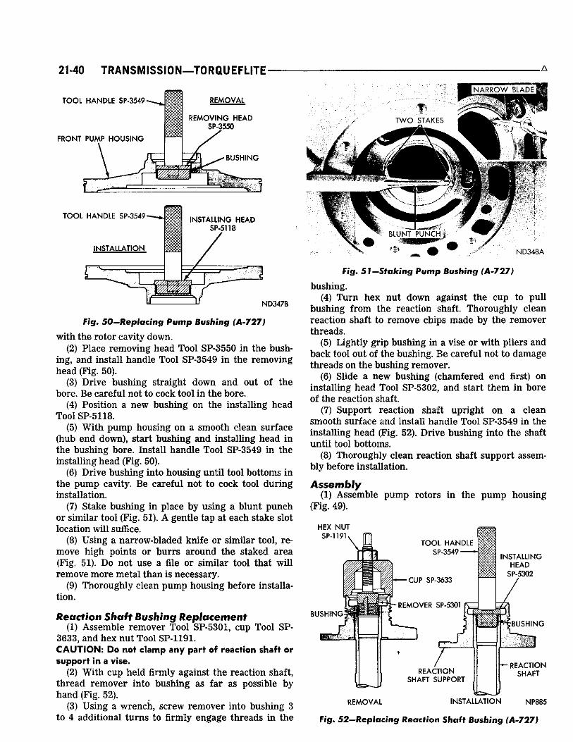
21-40 TRANSMISSION—TORQUEFLITE A
TOOL HANDLE SP-3549
FRONT PUMP HOUSING
REMOVAL
REMOVING HEAD SP-3550
WKA\KCW B L A D E ^
TOOL HANDLE SP-3549
ND347B
Fig. 50—Replacing Pump Bushing (A-727)
with the rotor cavi ty down. (2) P lace removing head T o o l SP-3550 in the bush
ing, and insta l l handle Too l SP-3549 in the removing head (F ig . 50).
(3) Dr ive bush ing straight down and out of the bore. B e care fu l not to cock tool in the bore.
(4) Posit ion a new bushing on the instal l ing head Too l SP-5118.
(5) W i t h pump housing on a smooth c lean sur face (hub end down), start bush ing and instal l ing head i n the bushing bore. Insta l l handle T o o l SP-3549 in the instal l ing head (F ig . 50).
(6) Dr ive bush ing into housing unt i l tool bottoms in the p u m p cavity. B e ca re fu l not to cock tool dur ing instal lat ion.
(7) Stake bush ing in place by us ing a blunt p u n c h or s imi lar tool (F ig . 51). A gentle tap at each stake slot location wi l l suffice.
(8) U s i n g a narrow-bladed kni fe or s imi lar tool, remove h igh points or b u r r s around the staked a rea (F ig . 51). D o not u s e a file or s imi la r tool that w i l l remove more meta l than is necessary .
(9) Thoroughly c lean pump housing before instal lat ion.
Reaction Shaft Bushing Replacement (1) A s s e m b l e remover Too l SP-5301, cup T o o l S P -
3633, and hex nut Too l SP-1191. CAUTION: Do not clamp any part of reaction shaft or support in a vise.
(2) Wi th c u p he ld f i rmly against the react ion shaft , thread r e m o v e r into bush ing as fa r as possible by hand (Fig. 52).
(3) U s i n g a w r e n c h , s c r e w remover into bushing 3 to 4 addit ional tu rns to firmly engage threads in the
TWO STAiCrS
i
ND348A
Fig. 51—Staking Pump Bushing (A-727)
bushing. (4) T u r n hex nut down against the cup to pu l l
bushing f rom the react ion shaft. Thoroughly c lean react ion shaft to remove chips made by the remover threads.
(5) L ight ly gr ip bushing in a v ise or wi th pl iers and back tool out of the bushing. B e care fu l not to damage threads on the bushing remover .
(6) Sl ide a new bushing (chamfered end first) on insta l l ing head Tool SP-5302, and start them i n bore of the react ion shaft.
(7) Support react ion shaft upr ight on a c lean smooth sur face and insta l l handle Too l SP-3549 in the insta l l ing head (F ig . 52). D r ive bushing into the shaft unt i l tool bottoms.
(8) Thoroughly c lean react ion shaft support assembly before instal lat ion.
Assembly (1) Assemble p u m p rotors in the pump housing
?m. 49). (F ig . 49).
HEX NUT SP-1191
INSTALLING HEAD
SP-5302
BUSHING ^BUSHING
REACTION SHAFT
SHAM SI IMW Ik? I •
REMOVAL INSTALLATION NP885
Fig. 52—Replacing Reaction Shaft Bushing (A-727)
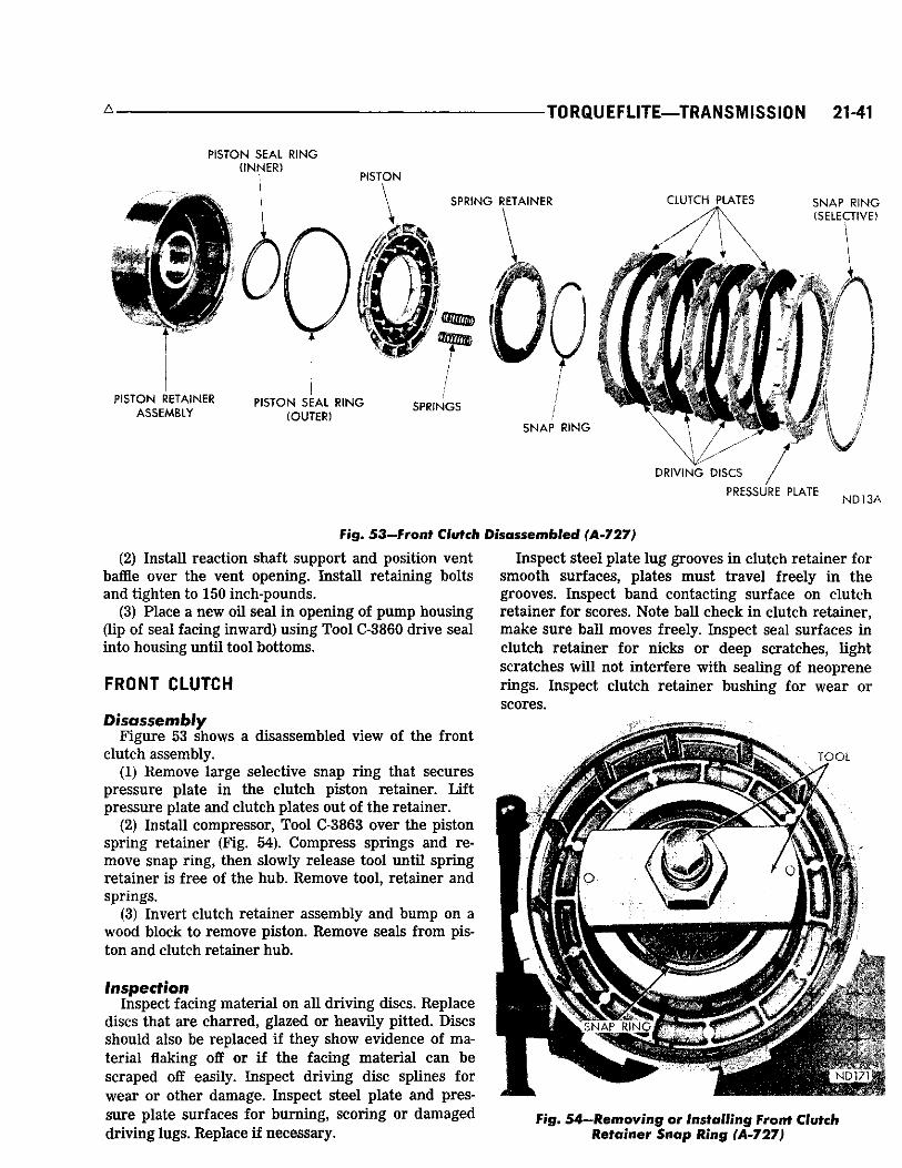
A TORQUEFLITE—TRANSMISSION 21-41
PISTON SEAL RING
Fig. 53—Front Clutch
(2) Insta l l react ion shaft support and position vent baffle over the vent opening. Insta l l retaining bolts and tighten to 150 inch-pounds.
(3) P lace a new oil sea l i n opening of pump housing (lip of seal facing inward) us ing T o o l C-3860 drive seal into housing unt i l tool bottoms.
FRONT CLUTCH
Disassembly F i g u r e 53 shows a d isassembled view of the front
c lutch assembly. (1) Remove large selective snap r ing that secures
pressure plate i n the c lutch piston retainer. L i f t p ressure plate and c lu tch plates out of the retainer.
(2) Insta l l compressor , Too l C-3863 over the piston spr ing reta iner (Fig. 54). Compress spr ings and remove snap r ing, then slowly re lease tool unt i l spr ing reta iner is f ree of the hub. Remove tool, reta iner and spr ings.
(3) Inver t c lutch reta iner assembly and bump on a wood block to remove piston. Remove seals f rom piston and c lutch reta iner hub.
Inspection Inspect facing mater ia l on a l l dr iv ing discs. Replace
discs that are char red , glazed or heav i ly pitted. D iscs should also be replaced if they show evidence of mater ia l flaking off or i f the fac ing mater ia l can be scraped off easily. Inspect dr iv ing disc spl ines for w e a r or other damage. Inspect steel plate and pressure plate sur faces for burn ing, scor ing or damaged dr iv ing lugs. Rep lace i f necessary .
sassembied (A-727)
Inspect steel plate lug grooves i n c lu tch re ta iner for smooth sur faces , plates must t rave l f reely i n the grooves. Inspect band contacting surface on c lu tch re ta iner for scores. Note bal l check i n c lutch reta iner , m a k e sure bal l moves freely. Inspect seal sur faces in c lu tch re ta iner for n icks or deep sc ra tches , ' l ight scra tches w i l l not inter fere wi th seal ing of neoprene r ings. Inspect c lutch reta iner bushing for w e a r or scores.
Fig. 54—Removing or Installing From® €lu$$h Retainer Snap Ring (A-727)

21-42 TRANSMISSION—TORQUEFLITE*
Inspect inside bore of piston for score m a r k s , i f l ight, remove wi th crocus cloth. Inspect sea l grooves for n icks and bur rs . Inspect neoprene seals for deterioration, wear , and hardness , and the piston spr ings, re ta iner and snap r ing for distort ion.
F r o n t Clutch Retainer Bushing Replacement (1) L a y c lutch re ta iner (open end down) on a c lean
smooth sur face and place removing head Too l S P -3629 in the bushing. Insta l l handle Too l SP-3549 in removing head (Fig. 55).
(2) Dr ive bushing straight down and out of c lutch reta iner bore. B e care fu l not to cock tool in the bore.
(3) L a y c lu tch re ta iner (open end up) on a c lean smooth sur face. Sl ide a new bushing on instal l ing head Too l SP-3628, and start them in c lu tch reta iner bore.
(4) Insta l l handle Too l SP-3549 in the insta l ler (F ig . 55. D r ive bushing into c lu tch re ta iner unt i l tool bottoms.
(5) Thoroughly c lean c lu tch re ta iner before assembly and instal lat ion.
Assembly (1) Lubr ica te and insta l l i nner sea l on hub of the
c lu tch reta iner . Make sure l ip of sea l faces down and is proper ly seated in the groove (F ig . 53).
(2) Insta l l outer sea l on the c lu tch piston, wi th l ip of sea l toward bottom of the c lu tch retainer . A p p l y a coating of wax type lubr icant or Door E a s e to outer edge of sea l for easier instal lat ion of the piston assembly. P lace piston assembly in re ta iner and carefu l ly seat piston in bottom of the reta iner .
(3) Insta l l spr ings as shown in F i g u r e s 56, 57 or 58.
TOOL HANDLE SP-3549
FRONT CLUTCH RETAINER
REMOVER HEAD SP-3629
REMOVAL
Ml
TOOL HANDLE SP-3549
INSTALLATION
INSTALLING HEAD SP-3628
ND350A
mm
NP143
Fig. 56—Front Clutch Piston Return Spring Location (10 Springs)
Posit ion spr ing reta iner and snap r ing over spr ings. Compress spr ings wi th Too l C-3863 (F ig . 54), and seat snap r ing in the hub groove.
(4) Lubr ica te a l l c lu tch plates, insta l l one steel plate fol lowed by a l ined plate unt i l a l l plates are instal led. Insta l l p ressure plate and selective snap r ing. Make sure snap r ing is proper ly seated.
(5) W i t h front c lu tch completely assembled, insert a feeler gauge between pressure plate and snap r ing (F ig . 59). T h e c learance should be .024 to .125 inch for 383 and 440 C u . In . E n g . or .066 to .123 inch for 440 H i g h Per fo rmance Eng ine . Insta l l a snap r ing of proper th ickness to obtain specified c learance. Snap
FRONT CLUTCH CHART (A-727)
Engine Clutch Plate Piston Type Discs Clearance Springs
383 C u . In. 4 .024 to .125" 8 (High. Pert.) 4 .024 to .125" 6
440 C u . In. 4 .024 to .125" 6 (High Pert.) 4 .066 to .123" 10
Fig. 55—Replacing Front Clutch Retainer Bushing (A-727)
NP144
Fig. 57—fr-orafr Clutch Piston Return Spr°mg Location (8 Springs)

A - TORQUEFLITE—TRANSMISSION 21-43
N U 4 6 2
Fig. 58—Front Clutch Piston Return Spring Location (6 Springs)
rings are the same as that used in rear c lutch and are available in .060 .062, .074-.076 and 088-.090 inch thickness.
R E A R C L U T C H
Disassembly F i g u r e 60 shows a disassembled view of the rear
c lutch assembly.
FEELER G A U G E
SELECTIVE SNAP RING
ND2
Fig, 59—Measuring Front Clutch Plate Clearance
(3) Inver t c lu tch piston re ta iner assembly and bump on a wood block to remove the piston. R e m o v e
(1) Remove large selective snap r ing that secures seals f rom the piston. (4) I f necessary , remove snap r ing and press input pressure plate in the c lutch retainer. L i f t p ressure
plate, c lutch plates, and inner pressure plate out of shaft f r o m the c lu tch piston retainer , the retainer.
(2) Care fu l ly p ry one end of wave spr ing out of its groove in the c lu tch retainer , then remove wave spr ing, spacer r ing and c lutch piston spr ing.
Inspection Inspect fac ing mater ia l on a l l dr iv ing discs. Replace
d iscs that are c h a r r e d , glazed or heavi ly pitted. D iscs
PISTON SPRING PRESSURE
PLATE
DRIVING DISCS
SNAP RING SELECTIVE)
l
PISTON RETAINER
CLUTCH RETAINER INPUT SHAFT PRESSURE
PLATE
SEAL RINGS (2)
m0-
CLUTCH PLATES
WAVE SPRING
SPACER RING
PISTON
SNAP RING
P I S T O N S E A L (OUTER)
THRUST WASHER ND165A
Fig. 60—Rear Clutch Disassembled (A-727)

21-44 TRANSMISSION—TORQUEFLITE
should also be rep laced if they show evidence of mater ia l flaking off or if fac ing mater ia l c a n be scraped off easi ly. Inspect dr iv ing disc spl ines for wear or other damage. Inspect steel plate and pressure plate sur faces for burn ing, scor ing or damaged dr iv ing lugs. Replace if necessary .
Inspect steel plate lug grooves in c lu tch reta iner for smooth sur faces , plates must t ravel f ree ly in grooves. Note bal l check in the piston, m a k e sure bal l moves freely. Inspect sea l sur faces in c lu tch reta iner for n icks or deep scratches, l ight scratches wi l l not inter fere with seal ing of neoprene seals. Inspect neoprene seals for deterioration, wear , and hardness . Inspect piston spr ing, wave spr ing, and spacer for distortion or breakage.
Inspect inter locking seal r ings (F ig . 60) on input shaft for wear or broken locks, m a k e sure they tu rn f ree ly in the grooves. Do not remove r ings un less condit ions warrant . Inspect bushing in the input shaft for w e a r or scores. Inspect rea r c lu tch to front c lu tch thrust washer for wear . W a s h e r th ickness should be .061 to .063 inch , replace if necessary .
Input Shaft Bushing Replacement (1) C l a m p input shaft i n a vise wi th soft j aws , being
care fu l not to c lamp on sea l r ing lands or journa ls . (2) Assemble remover Tool SP-3630, cup Too l S P -
3633, and hex nut Too l SP-1191. (3) W i t h cup he ld f i rmly against c lu tch piston re
tainer, thread remover into bush ing as f a r as possible by hand (Fig. 61).
(4) U s i n g a w r e n c h , sc rew remover into bush ing 3 to 4 addit ional tu rns to firmly engage threads in the bushing.
(5) T u r n hex nut down against cup to pu l l bush ing f rom the input shaft .
(6) Thoroughly c lean input shaft to remove chips made by remover threads. Make cer ta in s m a l l lubr i cat ion hole next to bal l i n end of shaft is not plugged
ND351A
Fig. 61— Replacing input Shaft Bushing (A-727)
_ , A
with chips. B e sure no chips are lodged next to the steel bal l .
(7) Sl ide a new bushing on instal l ing head Tool SP-3636, and start them in bore of the input shaft.
(8) S tand input shaft upr ight on a c lean smooth sur face and insta l l handle Tool SP-3549 in the instal l ing head (F ig . 61). Dr ive bushing into shaft unt i l tool bottoms.
(9) Thoroughly c lean input shaft and c lutch piston reta iner before assembly and instal lat ion.
Assembly (1) I f removed, press input shaft into c lutch piston
reta iner and instal l snap r ing . (2) Lubr ica te and insta l l inner and outer seal r ings
on the c lu tch piston. Make sure l ip of seals face tow a r d head of c lutch retainer , and are proper ly seated in the piston grooves (F ig . 60).
(3) P lace piston assembly in reta iner and, wi th a twist ing motion, seat piston in bottom of the retainer.
(4) Posit ion c lutch reta iner over piston reta iner spl ines and support the assembly so c lutch reta iner remains in place.
(5) P lace c lutch piston spr ing and spacer r ing on top of piston in c lutch reta iner , make sure spr ing and spacer r i n g are posit ioned in reta iner recess. Start one end of wave spr ing in the re ta iner groove (F ig . 62), then progressively push or tap spr ing into place mak ing sure it is ful ly seated in the groove.
(6) Insta l l inner pressure plate in c lutch reta iner wi th ra ised portion of plate rest ing on the spr ing.
(7) Lubr ica te a l l c lu tch plates, instal l one l ined plate fol lowed by a steel plate unt i l a l l plates are instal led. Insta l l outer p ressure plate and selective snap r ing.
(8) Measure rear c lu tch plate c learance by hav ing an assistant press downward firmly on the outer pressure plate, then insert a feeler gauge between
Fig. 62—Installing Rear Clutch Spring, Spacer Ring and Wave Spring

A
plate and snap r ing (Fig. 63). T h e c learance should be between .025 to .045 inch. If not, insta l l a snap r ing of proper th ickness to obtain specif ied c learance . L o w l imit c learance is desirable. Rear clutch plate clearance is very important in obtaining proper clutch operation. The clearance can be adjusted by the use of various thickness outer snap rings. Snap rings are available in .060-.062, .074-.076, .088-.090 and .106-.108 inch thickness.
PLANETARY GEAR TRAIN
Measure end play of planetary gear assembl ies, sun gear and dr iv ing shel l before removing these parts f rom the output shaft. Wi th the assembly in an upright posit ion, push rear annulus gear support downward on the output shaft. Inser t a fee ler gauge between rear annulus gear support hub and shoulder on the output shaft (Fig. 64). T h e c learance should be .010 to .037 inch . I f c learance exceeds specifications, replace thrust washers a n d / o r necessary parts.
Disassembly (1) Remove thrust washer f rom forward end of the
output shaft (Fig. 65). (2) Remove selective snap r ing f rom forward end of
output shaft, then slide front planetary assembly off the shaft.
(3) Sl ide front annulus gear off the planetary gear set (Fig. 65). Remove thrust washer f rom rear side of the planetary gear set.
(4) Sl ide sun gear, dr iv ing shel l and r e a r planetary assembly off the output shaft.
3 a r a w e IA? R I N G
Fig. 63—Measuring Rear Clutch Plate Clearance
TORQUEFLITE—TRANSMISSION 21-45
Fig. 64—Measuring End Play of Planetary Gear Assemblies
(5) L i f t sun gear and dr iv ing shel l off rear planetary gear assembly. R e m o v e thrust w a s h e r f rom inside the dr iv ing shel l . R e m o v e snap r ing and steel washer f rom sun gear (rear side of dr iv ing shell) and sl ide sun gear out of the she l l . Remove front snap r ing f rom the s u n gear if necessary . Note that front end of sun gear is longer than the rear .
(6) Remove thrust w a s h e r f rom forward side of r e a r planetary gear assembly, remove planetary gear set and thrust plate f rom the r e a r annulus gear.
Inspection' Inspect bear ing sur faces on output shaft for n icks,
bur rs , scores or other damage. L i g h t scratches, smal l n icks or bur rs can be removed wi th crocus cloth or a fine stone. Inspect speedometer dr ive gear for any n icks or bur rs , and remove wi th a sharp edge stone. Make sure a l l oil passages i n the shaft are open and clean.
Inspect bushings in sun gear for wear or scores, replace sun gear assembly if bushings are damaged. Inspect a l l thrust washers for wear and scores, replace if damaged or worn below specifications. Inspect thrust faces of planetary gear car r ie rs for wear, scores or other damage, replace as requi red . Inspect planetary gear ca r r i e r for c racks and pinions for broken or worn gear teeth and for broken pinion shaft lock pins. Inspect annulus gear and dr iv ing gear teeth for damage. Rep lace distorted lock r ings .
Assembly R e f e r to F i g u r e 65 for parts re ferences. (1) Insta l l r e a r annulus gear on the output shaft.
A p p l y a th in coat of grease on thrust plate, place it on the shaft and in the annulus gear m a k i n g sure teeth are over the shaft spl ines.
(2) Posit ion r e a r planetary gear assembly in rear

21-46 TRANSMISSION—TORQUEFUTE- A
annulus gear. P lace thrust washer on front side of the planetary gear assembly.
(3) Insta l l snap r ing in front groove of sun gear (long end of gear). Inser t sun gear through front side of dr iv ing shel l , insta l l r ea r steel washer and snap r ing.
(4) Care fu l ly sl ide dr iv ing shel l and sun gear assembly on the output shaft, engaging sun gear teeth wi th r e a r planetary pinion teeth. P lace thrust w a s h e r inside front of the dr iv ing shel l .
(5) P lace thrust washer on r e a r hub of front planetary gear set, then sl ide assembly into front annu lus gear.
(6) Care fu l ly work front planetary and annulus gear assembly on the output shaft , meshing planetary pinions wi th the sun gear teeth.
(7) W i t h a l l components proper ly posit ioned, insta l l selective snap r ing on front end of the output shaft. Re -measure end play of the assembly. The clearance can be adjusted by the use of various thickness snap rings. Snap rings are available in .048-.052, .055-.059 and .062-.066 inch thickness.
OVERRUNNING CLUTCH
Inspection
Inspect c lutch ro l lers for smooth round sur faces , they must be free of flat spots and chipped edges. Inspect ro l ler contacting sur faces in the c a m and race for br inel l ing. Inspect rol ler spr ings for distort ion, wear or other damage. Inspect c a m set sc rew for t ightness. I f loose, t ighten and restake case around the screw.
Overrunning Clutch Cam Replacement I f over running c lu tch cam a n d / o r ro l ler spr ing re
ta iner are found damaged, replace c a m and spr ing
FRONT S N A P R I N G A N N U L U S G E A R ( S E L E C T I V E ) A S S E M B L Y
\ O U T P U T X S H A F T
S U P P O R T NN129
F ig. 66—Removing Overrunning Clutch Cam (A-727)
reta iner in the fol lowing manner: (1) Remove set screw f rom case below the c lu tch
cam. (2) Remove four bolts secur ing output shaft sup
port to rear of the t ransmission case. Inser t a p u n c h through the bolt holes and dr ive c a m f r o m the case (F ig . 66). A l ternate the punch f rom one bolt hole to another so cam wi l l be dr iven evenly f rom the case. IMPORTANT: The output shaft support must be in the case to install the overrunning clutch cam.
If the support requires replacement, drive it rearward out of the case with a wood block and hammer. Te install^ screw two C-32S8 pilot studs into the case (Fig. 67). Chill the support with ice (preferably dry ice). Quickly position support over the pilot studs, and drive it firmly into the case with a wood block and hammer .
(3) C l e a n a l l bur rs and chips f rom cam area in the case.
THRUST W A S H E R
/ S U N G E A R
/
D R I V I N G S H E L L
I
F R O N T \ " \
P L A N E T A R Y GEAR T H R U S T W A S H E R S N A P R I N G
A S S E M B L Y
T H R U S T W A S H E R ( S T E E L )
T H R U S T W A S H E R
R E A R P L A N E T A R Y G E A R
A S S E M B L Y
j THRl I W A S
R E A R A N N U L U S G E A R A S S E M B L Y
S N A P R I N G / ." l- .RUST P L A T E
T H R U S T W A S H E R
N K I 4 4 B O U T P U T S H A F T L O W A N D R E V E R S E D R U M
Fig. 65—Planetary Gear Train and Output Shaft Disassembled (A-727)
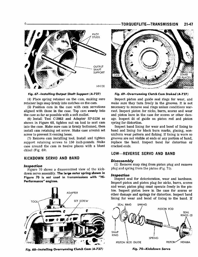
-TORQUEFLITE—TRANSMISSION 21-47
PILOT STUDS
O U T P U T S H A F T S U P P O R T
NN130
Fig. 67-lnstalling Output Shaft Support (A-727)
(4) Place spring retainer on the cam, making sure retainer lugs snap firmly into notches on the cam.
(5) Position cam i n the case w i t h cam serrations aligned w i th those i n the case. Tap cam evenly into the case as far as possible w i th a soft mallet.
(6) Instal l Tool C-3863 and Adapter SP-5124 as shown i n Figure 68, t ighten nut on tool to seat cam into the case. Make sure cam is firmly bottomed, then instal l cam retaining set screw. Stake case around set screw to prevent i t coming loose.
(7) Remove cam instal l ing tool. Instal l and t ighten support retaining screws to 150 inch-pounds. Stake case around the cam in twelve places w i th a b lunt chisel (Fig. 69).
KICKDOWN SERVO AND BAND
Inspect i o n Figure 70 shows a disassembled view of the kick-
down servo assembly. T h e large outer spring shown in Figure 70 is not used in t ransmissions with " H i -Per fo rmance" engines.
*4 -Si
TOOL \ / .M. -
A D A P T E R
SET S C R E W
/ Iv jfc- < . ***** /
CAM •k i l l ^ ^ ^ ^ ^ ^
STAKE (12) PLACES
N N 1 3 2 A
Fig. 69—O^errnnni i ig Clutch Cam Staked (A-727)
inspect piston and guide seal rings f o r wear, and make sure they t u r n freely i n the grooves. I t is not necessary to remove seal rings unless conditions warrant. Inspect piston for nicks, burrs, scores and wear and piston bore i n the case for scores or other damage. Inspect fit of guide on piston rod and piston spring for distort ion.
Inspect band l in ing for wear and bond of l in ing to band and l in ing for black burn marks, glazing, nonuni form wear pattern and flaking. I f l in ing is worn so grooves are not visible at ends or any port ion of band, replace the band. Inspect band for distort ion or cracked ends.
LOW—REVERSE SERVO AND BAND
Disassembly (1) Remove snap r i n g f rom piston plug and remove
plug and spring f rom the piston (Fig. 71).
Inspection Inspect seal for deterioration, wear and hardness.
Inspect piston and piston p lug for nicks, burrs, scores and wear; piston p lug must operate freely i n the piston. Inspect piston bore i n the case for scores or other damage and springs for distortion. Inspect band l in ing for wear and bond of l in ing to the band. I f
SEAL RING SPRING N / PISTON ROD SEAL
R I N G S (2)
A. i'j. >
SNAP R I N G
1
SPRING
NN131--4- PISTON ROD GUIDE r • Kin PISTOKK ND168A
Fig. 68-lnstalling Overrunning Clutch Cam (A-727) Pig. 70-Kickdown Servo

21-48 TRANSMISSION—TORQUEFLITE A
SEAL R I N G
| P I S T O N
P I S T O N S P R I N G
P I S T O N PLUG
I
mkm
P i U G S P R I N G S P R I N G RETAINER S N A P R I N G
S N A P R I N G INP i 47
Fig. 71—tow and Reverse Servo
l in ing is worn so grooves are not v isible at ends or any portion of band, replace the band. Inspect band for distortion or c racked ends.
Assembly (1) Insta l l piston p lug and spr ing in the piston and
secure wi th snap r ing.
ASSEMBLY—SUB-ASSEMBLY INSTALLATION
T h e assembly procedures given here inc lude installat ion of sub-assemblies in the t ransmiss ion case and adjust ing dr ive t ra in e n d play. Do not use force to assemble mat ing parts. I f parts do not assemble freely , investigate cause, and correct the trouble before proceeding wi th assembly procedures. A l w a y s use new gaskets dur ing assembly operations. IMPORTANT: Use only Automat ic Transmission Fluid A Q - A T F Suffsx " A " {Dexron} to l u b r i c a t e t r a n s m i s s i o n
parts during assembly.
Overrunning Clutch (1) W i t h t ransmiss ion case i n an upr ight posit ion,
inser t c lu tch hub inside the cam. Insta l l over runn ing c lu tch ro l lers and spr ings exact ly as shown in F i g u r e 72.
Low—Reverse Servo and Band (1) Care fu l ly work servo piston assembly into the
case with a twist ing motion. P lace spr ing, reta iner and snap r ing over the piston (F ig . 71).
(2) Compress low and reverse servo piston spr ing by us ing engine valve spr ing compressor Too l C-3422, then insta l l snap r ing .
(3) Posi t ion r e a r band in the case, insta l l short strut , then connect long l ink and anchor to the band (F ig . 73). S c r e w in band adjuster just enough to hold strut in place. B e sure long l ink and anchor assembly is instal led, as shown in F i g u r e 72 to provide a runn ing c learance for the low and reverse d r u m . Ins ta l l the low-reverse d r u m .
Kickdown Servo (1) Care fu l ly p u s h servo piston into the case bore.
Insta l l piston rod , two spr ings and the guide (F ig . 70). The transmission used with "Hl-Performance" en-
Fig. 72—Overrunning Clutch, Low and Reverse Band Link
gines, use only one small inner spring in the kick-down servo.
(2) Compress k ickdown servo spr ings by us ing engine valve spr ing compressor Too l 3422, then insta l l snap r ing.
Planetary Gear Assemblies, Sun Gear and Driving Shell
(1) Wh i le support ing assembly i n the case, inser t output shaft through the r e a r support . Care fu l l y w o r k assembly r e a r w a r d engaging r e a r p lanetary c a r r i e r
ADJUSTING SCREW AND LOCKNUT
LEVER - LEY-R : $ - C I > T t
1/ B A N D
ND21
Fig. 73—Low-Reverse Band and Linkage

TORQUEFLITE—TRANSMISSION 21-49
lugs into the low-reverse d r u m slots. C A U T I O N : Be very carefu l not to damage ground sur faces on output shaft dur ing instal lat ion.
Front cruel Rear Cluteh Assemblies T h e front and r e a r c lutches, front band, pump and
reaction shaft support a re more easi ly instal led wi th transmission in an upr ight position.
I f t ransmission repai r stand DD-1014 was not avail able to support t ransmiss ion, an alternate method is outlined in Steps 1 and 2.
(1) Cu t a 3-1 /2 inch diameter hole in a bench, i n the end of a smal l oil d r u m or a large wooden box strong enough to support t ransmission. Cut or file notches at the edge of the 3-1 /2 inch hole so output shaft support wi l l fit and lay flat in the hole.
(2) Carefu l ly insert output shaft into the hole to support the t ransmission upright , wi th its weight resting on flange of the output shaft support.
(3) App ly a coat of grease on the input to output shaft thrust washer (F ig . 65), and instal l the washer on front end of the output shaft.
(4) A l ign front c lu tch plate inner spl ines, and place assembly in position on the r e a r c lutch. Make sure front c lutch plate spl ines are ful ly engaged on the rear c lutch spl ines.
(5) A l ign rear c lu tch plate inner spl ines, grasp input shaft and lower the two c lutch assemblies into the transmission case.
(6) Carefu l ly w o r k c lu tch assembl ies in a c i rcu la r motion to engage rear c lutch spl ines over spl ines of the front annulus gear. Make sure front c lutch dr ive lugs are ful ly engaged in slots in the dr iv ing shel l .
Front Bond F i g u r e 74 shows disassembled view of the kick-
down band assembly. (1) Sl ide the band over front c lu tch assembly. (2) Insta l l the band strut , screw i n adjuster jus t
enough to hold strut and anchor in place.
NDI7
Fig. 74—fCicfcdown Band and Linkage
Oil Pump and Reaction Shaft Support I f difficulty was encountered in removing the oil
p u m p assembly due to an exceptionally tight fit i n the case , it m a y be necessary to expand the case wi th heat dur ing pump installation. U s i n g a suitable heat l amp, heat the case i n area of the pump for a few minutes pr ior to instal l ing pump and react ion shaft support assembly.
I f dr ive t ra in end play was not wi thin specif ications .037-.084 inch) w h e n measured, replace the thrust w a s h e r on reaction shaft support hub wi th one of proper th ickness (Fig. 49).
T h e fol lowing selective thrust washers are avai l able: Thickness Color
.061-.063 inch G r e e n
.084-.086 inch R e d
.102- .104 inch Y e l l o w
(1) S c r e w two pilot studs, Tool C-3288 in oil pump opening i n the case (Fig. 75). Insta l l a new gasket over the pilot studs.
(2) P l a c e a new rubber seal r ing in the groove on outer flange of pump housing. Make sure seal r ing is not twisted. Coat sea l r ing with grease for easy instal lat ion.
(3) Insta l l pump assembly in the case, tap it l ight ly w i th a soft mal let i f necessary. P lace the deflector over vent opening and instal l four pump body bolts. R e m o v e pilot studs, instal l remain ing bolts and s n u g al l bolts down evenly.
Rotate input and output shafts to see if any binding exists, then tighten bolts to 175 inch-pounds. C h e c k shafts again for free rotation.
Fig. 75—Installing Pump and Reaction Shaft Support Assembly
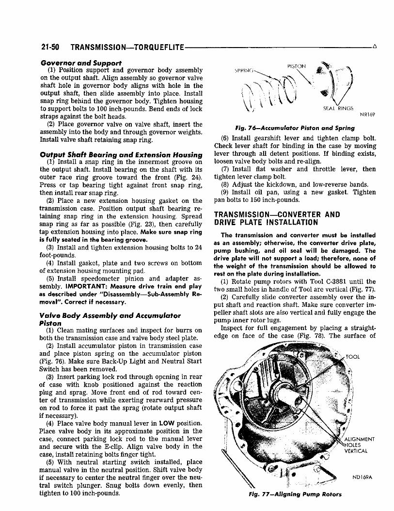
21 -50 TRANSMISSION—TORQUEFLITE-
Governor and Support (1) Posit ion support and governor body assembly
on the output shaft. A l i g n assembly so governor valve shaft hole in governor body al igns wi th hole in the output shaft, then sl ide assembly into place. Instal l snap r ing behind the governor body. T ighten housing to support bolts to 100 inch-pounds. B e n d ends of lock straps against the bolt heads.
(2) P lace governor valve on valve shaft , inser t the assembly into the body and through governor weights. Insta l l valve shaft reta ining snap r ing .
Output Shaft Bearing and Extension Housing (1) Insta l l a snap r ing in the innermost groove on
the output shaft. Insta l l bear ing on the shaft wi th its outer race r ing groove toward the front (F ig . 24). P r e s s or tap bear ing tight against front snap r ing , then instal l rear snap r ing.
(2) P lace a new extension housing gasket on the t ransmission case. Posit ion output shaft bear ing retaining snap r ing in the extension housing. Spread snap r ing as far as possible (F ig . 23), then carefu l ly tap extension housing into place. Make sure snap ring is fully seated in the bearing groove.
(3) Instal l and tighten extension housing bolts to 24 foot-pounds.
(4) Instal l gasket, plate and two screws on bottom of extension housing mount ing pad.
(5) Instal l speedometer pinion and adapter assembly. IMPORTANT: Measure drive train end play as described under ''Disassembly—Sub-Assembly Re~ mova I" . Correct if necessary.
Valve Body Assembly and Accumulator Piston
(1) C lean mat ing sur faces and inspect for b u r r s on both the t ransmission case and valve body steel plate.
(2) Instal l accumulator piston in t ransmission case and place piston spr ing on the accumulator piston (Fig. 76). Make sure B a c k - U p L i g h t and Neut ra l Start Swi tch has been removed.
(3) Insert park ing lock rod through opening in rear of case with knob posit ioned against the react ion plug and sprag. Move front end of rod toward center of t ransmission whi le exer t ing r e a r w a r d pressure on rod to force it past the sprag (rotate output shaft if necessary) .
(4) P lace valve body m a n u a l lever in L O W position. P lace valve body in its approximate position in the case, connect park ing lock rod to the manua l lever and secure wi th the E-c l ip . A l i g n valve body in the case, instal l reta ining bolts finger tight.
(5) Wi th neutra l start ing swi tch instal led, p lace manua l valve in the neutra l position. Shift valve body if necessary to center the neut ra l finger over the neut ra l swi tch plunger . S n u g bolts down evenly, then tighten to 100 inch-pounds.
P l o T O M
EAL RINGS NR169
Fig. 76—Accumulator Piston and Spring
(6) Insta l l gearshift lever and tighten c lamp bolt. C h e c k lever shaft for binding in the case by moving lever through a l l detent positions. I f b inding exists, loosen valve body bolts and re-al ign.
(7) Insta l l flat washer and throttle lever, then tighten lever c lamp bolt.
(8) A d j u s t the k ickdown, and low-reverse bands. (9) Instal l oil pan , us ing a new gasket. T ighten
pan bolts to 150 inch-pounds.
TRANSMISSION—CONVERTER AND DRIVE PLATE INSTALLATION
The transmission and converter must be installed as an assembly; otherwise, the converter drive plate, pump bushing, and oil seal will be damaged.. The drive plate will not support a load; therefore, none of the weight of the transmission should be allowed to rest on the plate during installation.
(1) Rotate pump rotors with Tool C-3881 unt i l the two sma l l holes in handle of Tool are vert ica l (F ig . 77).
(2) Carefu l ly sl ide converter assembly over the input shaft and react ion shaft. Make sure converter impel ler shaft slots are also ver t ica l and ful ly engage the pump inner rotor lugs.
Inspect for fu l l engagement by placing a straightedge on face of the case (F ig. 78). T h e surface of
root
N \ ALIGNMENT '"XV;OLE$
VERTICAL
ND169A
Fig. 77—Aligning; Pump Rotors

-T0RQUEF5JTE—TRANSMISSION 21-51
^ ^ ^ ^ ^ ^ ^ ^ ^ ^ ^ ^ ^ ^ ^
MO 6
Fig. 78—Hfeesprffig Converter for Full fngagemenf in Transmission
converter f ront cover lug should be at least 1/2 inch rear of straightedge when converter is pushed a l l way into the transmission.
(3) Attach a small " C " clamp to edge of converter housing to hold converter i n place dur ing transmission installation.
(4) Inspect converter drive plate for distortion or cracks and replace i f necessary. Torque Drive Plate to Crankshaft bolts to 55 foot pounds. When Drive Plate replacement has been necessary, make sure transmission dowel pins are in engine block and pro-
REAR MOUNT' 4 - ;
FRANSM1SSION EXT . HOUSING
V
, r • - DRAIN PLUG
J, c
HIH^HP9B lil^l^HP!&fli
ND10 "v" M A R K
Fig. 79—Converter and Drive Plate Markings
truding far enough to hold transmission in alignment. (5) Coat converter hub hole i n crankshaft w i th
wheel bearing lubricant. Place transmission and converter assembly on a service jack and position assembly under vehicle for installation. Raise or t i l t as necessary u n t i l transmission is aligned w i t h the engine.
(6) Rotate converter so mark on converter (made dur ing removal) w i l l align w i th mark on drive plate.
CENTER CROSSMEMBER
TIGHTENING TORQUE
50 FT. LBS.
75 FT. LBS.
l . 40 FT. LBS.
NU48A
Fig. 80—Center Crossmember and Rear Engine Mount

21-52 TRANSMISSION—TORQUEFLITE
T h e offset holes in plate are located next to the 1 /8 inch hole in the inner c i rc le of the plate. A stamped V m a r k identifies offset hole in the converter front cover (Fig. 79). Carefu l ly work t ransmission forward over engine block dowels wi th converter hub enter ing the crankshaf t opening.
(7) Af ter t ransmission is in position, insta l l converter housing bolts and tighten to 28 foot-pounds.
(8) Instal l two lower dr ive plate to converter bolts and tighten to 270 inch-pounds.
(9) Instal l start ing mtotor and connect battery ground cable.
(10) Rotate engine with Remote Contro l Swi tch and instal l the other two dr ive plate to converter bolts. T ighten bolts to 270 inch-pounds.
(11) Insta l l c rossmember a n d tighten attaching bolts to 75 foot-pounds. Imperial Models: Posit ion center c rossmember in the stub f rame. Start a l l reta ining bolts inc luding the four rubber isolator bolts, then tighten a l l bolts to 75 foot-pounds.
(12) L o w e r t ransmission so extension housing is al igned and rests on rear mount. Insta l l bolts and tighten to 40 foot-pounds (F ig . 80). E n g i n e mount to center c rossmember bolt and nut, loose assembled to this point, should now be torqued to 50 foot-pounds.
(13) Insta l l gearshif t torque shaft and connect gearshift rod to the t ransmission lever .
Console Shift: A l i g n gearshift torque shaft lower bracket wi th the extension housing. Insta l l the two retaining bolts and t ighten secure ly . Connect gearshift rod to the t ransmission lever .
(14) Care fu l ly guide s l id ing yoke into extension housing and on the output shaft spl ines. A l i g n m a r k s made at removal then connect propel ler shaft to the rear axle pinion shaft yoke.
(15) Connect oil cooler l ines to the t ransmission. Insta l l the oil filler tube. Connect the speedometer cable.
(16) Connect throttle rod to be l lc rank at left side of t ransmission bel l housing.
(17) Connect w i re to the back-up light and neutra l start ing swi tch.
(18) Insta l l cover plate in front of the converter assembly.
(19) Ref i l l t ransmiss ion wi th Automat ic T ransmis sion F l u i d , A Q - A T F Suffix " A " (Dexron).
(20) A d j u s t throttle and gearshif t l inkage.
FLUID LEAKAGE—TRANSMISSION CONVERTER HOUSING AREA
(1) Check for Source of Leakage Since fluid leakage at or around the converter area
m a y originate f rom an engine oil leak, the area should be examined closely. F a c t o r y fill fluid is dyed red and, therefore, can be dist inguished f rom engine oil .
A
(2) P r io r to removing the t ransmission, per form the following checks:
W h e n leakage is determined to originate f rom the transmission, check fluid level and torque converter dra in plug torque pr ior to removel of the t ransmission and torque converter .
H igh oil level can resul t in oil leakage out the vent located at the top of the front pump housing. I f the fluid leve l is h igh, adjust to proper level .
Oi l leakage can also occur at the torque converter dra in plug. Torque the dra in p lug to 110 inch-pounds.
Af ter per forming these two operations, re-check for leakage. I f a leak persists, per form the fol lowing operation on the car to determine whether it is the converter or transmission that is leaking.
LEAKAGE TEST PROBE
(1) Remove converter housing dust shie ld. (2) Posit ion vehicle with front lower than back so
that accumulated fluid in converter housing wi l l dra in out. Wipe bottom inside of converter housing as dry as possible. A solvent spray fol lowed by compressed air dry ing is preferable.
(3) F a s t e n test probe (Fig. 1) securely to convenient dust shield bolt hole. Make certa in converter is c leared by test probe. Tool must be c lean and dry.
(4) R u n engine at approximately 2,500 r p m with transmission in neutra l , for about 2 minutes. T rans mission must be at operating temperature.
(5) Stop engine and carefu l ly remove tool. (6) I f upper surface of test probe is dry, there is no
converter leak. A path of fluid across probe indicates a converter leak. Oi l leaking under the probe is coming f rom the t ransmission converter area (Fig. 2).
(7) Remove t ransmission and torque converter assembly f rom vehicle for fur ther investigation. T h e fluid should be dra ined f rom the t ransmission and converter . Re- instal l converter dra in p lug and oil pan (with new gasket) at specified torque.
Possible sources of t ransmission converter area fluid leakage shown in (Fig. 2) are:
SHIELD MATERIAL: 5-1/2" X 1-1/2" X
BOLT 1/32" SHEET METAL PY300
Fig. I—Leak Locating Test Probe Tool

A - -TORQUEFUTE—TRANSMISSION 21-53
V f N T Sr! KLO USED * jy-* * : ~ -v~ O N A - 7 2 7 O M Y «
•4 4 * 0 - ^ i -4- "3
Hi 4 v -i
•: SEAL ' N S T A L L I N G T O O L
PV3C1
Fig. 2—Transmission Converter Area
(1) Converter Hub Seal (a) Seal l ip cut, check converter hub finish. (b) Bushing moved and/or worn. (c) Oi l r e turn hole i n front pump housing
plugged or omitted. (d) Seal worn out (high mileage cars).
(2) F lu id leakage at the outside diameter f rom pump housing " 0 " r ing seal.
(3) F lu id leakage at the f ront pump to case bolts. (4) F lu id leakage due to case or f ront pump housing
porosity. (5) Oil leakage out the vent. (6) Kickdown lever shaft access plug. Possible sources of converter leakage shown in (Fig.
3) are: (1) Torque converter weld leaks at the outside diam
eter (peripheral) weld. (2) Front pump hub weld. (3) Crankshaft pi lot weld. (4) F lu id leakage f rom the converter drain plug.
These leaks appear at the outside diameter of the converter on the engine side.
AIR P R E S S U R E TEST OF TRANSMISSION The transmission should be prepared for pressure
OUTSIDE DIAMETER W E L D O R G U E CONVERTER
DRAIN S
R I N G GEAR C R A N K S H A F T PILOT W E L D PLUG PY16
Fig. 3—Torque Converter Cross Sect/on
V E N T P L U G RETAINER
S L I D I N G YOKE W I R E D I N PLACE /
HHBf lHHB
RETAINER i
S P R I N G *
X P L U G — M A D E F R O M
O L D FILLER TUBE
\ C O N V E R T E R
H U B SEAL C U P
PY302
Fig. 4—Transmission Prepared for Test
test as follows after removal of the torque converter: (1) Instal l filler tube bore plug, propeller shaft yoke
(tie i n w i th cord or wire), flared tube fitting cap (on
FLARE C A P n
\
A I R P U M P C-3499
WELD OR BRAZE
HOSE C L A M P PY303
Fig. 5—Pressurizing Transmission
BREAK EDGE 1/16" MIN.
MATERIAL: 1-7/8 INCH O.D. THIN WALLED STEEL TUBING AND 1/8 INCH STEEL DISC
- 1 8 7 3
POLISH 1-876 OUTSIDE OF OPEN END FOR THIS DISTANCE O N TUBE
PY304
Fig. 6—A-727—Converter Hub Seat Cup

21-54 TRANSMISSION—3-SPEED MANUAL
15/32" DRILL 4 HOLES
-1-13/64" 14-3/16" H
— 1 6 - 1 / 2 " — - H h 17-19/32" " H
^ 2 0 " •
MATERIAL: 1/4" STEEL STOCK 1-1/4" WIDE PY306
Fig. 7—Hub Seal Cup Retaining Strap
front cooler l ine fitting), and pipe nipple (in case at rea r cooler l ine fitting) (Fig. 4 and 5).
(2) Remove necessary front pump housing bolts, and vent shie ld (in A-727 transmission) . Insta l l vent p lug (rubber stopper), and vent plug re ta iner (F ig . 4) preferably us ing longer bolts than those removed.
(3) Wi th rotary motion, instal l converter hub seal cup (Fig. 4), over input shaft, and through the conver ter hub seal unt i l the cup bottoms against the pump rotor lugs. Secure with cup reta iner strap (Fig. 4), us ing converter housing to engine block reta ining bolts.
(4) A t tach and c lamp hose f rom nozzle of Tool C -3499 to pipe nipple, wh ich is in rea r cooler l ine fitting position in case (Fig. 5).
(5) Pressur ize the t ransmission us ing Tool C-3499, unt i l the pressure gage reads 8 psi . Posit ion t ransmission so that pump housing and case front may be covered with soapy solution or water. L e a k s are somet imes caused by porosity in the case or pump housing. C A U T I O N : Do not, under any c i rcumstances, pressur ize a t ransmission to more than 10 psi .
If a leak source is located, that part and al l associated seals and gaskets should be replaced wi th new parts.
MATERIAL: 3/16" STEEL STOCK PY307
Fig. 8-A-727-Vent Plug Retainer
Fabr icate equipment needed for test as shown in (Figs. 1, 6, 7, & 8).
TORQUE CONVERTER P R E S S U R E TEST
I f fluid leakage has occurred in the bel l housing area , the torque converter can be leak checked as follows after removal f rom the t ransmission:
(1) Dra in al l oil f rom the converter . If flushing is requi red, flush before check ing for leakage.
(2) Instal l tool C-4102 and t ighten. (3) App ly a m a x i m u m of 100 psi air pressure to
the converter . (4) Submerge the converter in a tank of water and
observe the hub, cup, r ing gear, and seam welds for bubbles. F i v e to ten minutes may be requi red for bubbles to develop f rom smal l leaks.
I f no bubbles are observed, it can be assumed that the welds are not leaking. I f leakage occurs , the conver ter should be replaced.
MANUAL TRANSM!SSION-(A-230)
THREE SPEED
General Information Serv ice Diagnosis Serv ice in Vehicle
Extension Housing Yoke Sea l Gearshift Linkage Adjustment Speedometer Pinion Gear . .
Serv ice Out of Vehicle Assembl ing Transmiss ion
INDEX
Page Page . 55 Cleaning and Inspection 61 . 55 Disassembl ing Transmiss ion . . . . . . . . . . . . . . . . . 57
Extension Housing Bushing Replacement . 64 . 67 Transmiss ion Installation 65 . 67 Transmiss ion Removal 57 . 67 Specif icat ions . . . . . . . . . 69
Tightening Reference 70 . 62
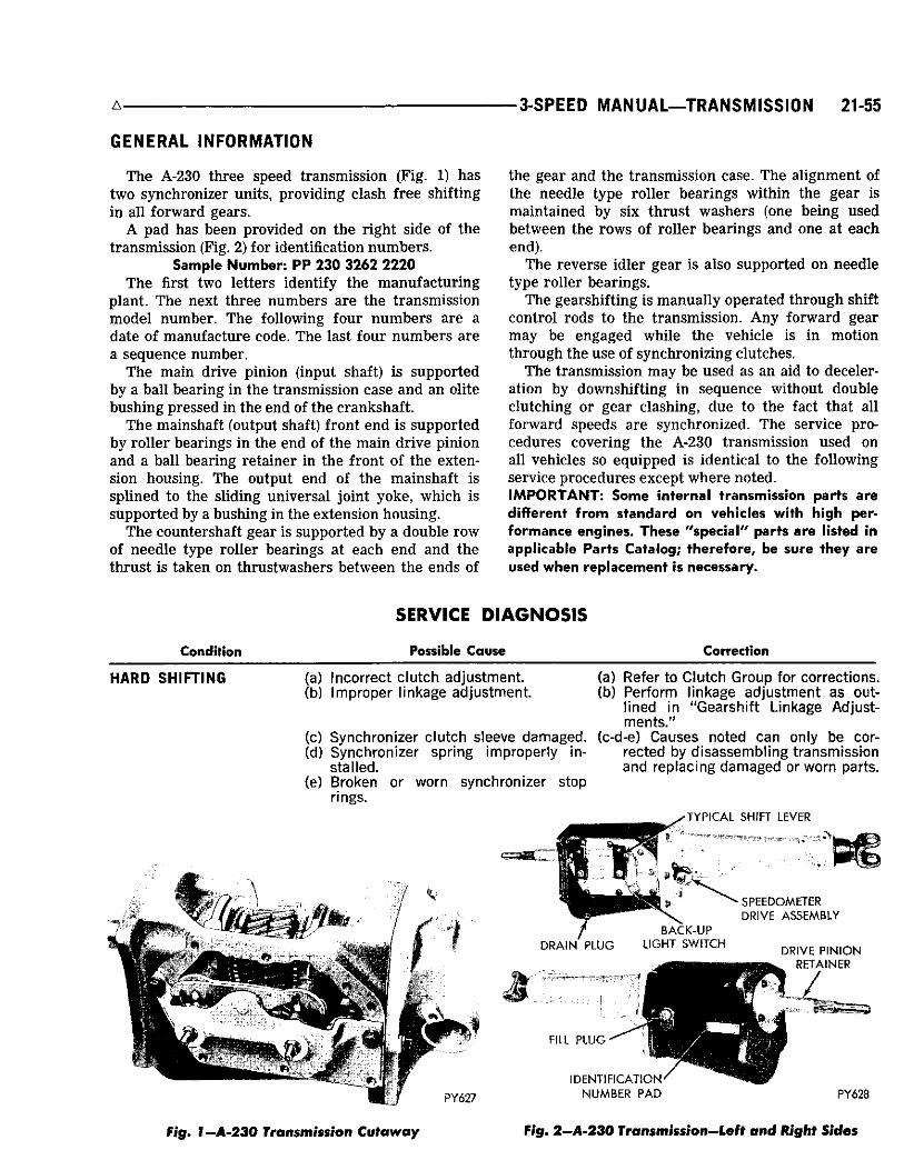
3-SPEED M A N U A L — T R A N S M I S S I O N 21-55
GENERAL INFORMATION
T h e A-230 three speed t ransmission (F ig . 1) has two synchronizer units, providing c lash f ree shift ing in a l l forward gears.
A pad has been provided on the r ight side of the t ransmission (Fig. 2) for identification numbers .
Sample Number: P P 230 3262 2220 T h e first two letters identify the manufactur ing
plant. T h e next three numbers are the t ransmiss ion model number . T h e following four n u m b e r s are a date of manufacture code. T h e last four numbers are a sequence number .
T h e main dr ive pinion (input shaft) is supported by a bal l bear ing in the transmission case and an olite bushing pressed in the end of the crankshaf t .
T h e mainshaft (output shaft) front end is supported by ro l le r bearings in the end of the main dr ive pinion and a bal l bear ing reta iner in the front of the extension housing. T h e output end of the mainshaft is spl ined to the sl iding un iversa l joint yoke, wh ich is supported by a bushing in the extension housing.
T h e countershaft gear is supported by a double row of needle type rol ler bearings at each end and the thrust is taken on thrustwashers between the ends of
the gear and the t ransmiss ion case. T h e al ignment of the needle type ro l ler bear ings within the gear is maintained by six thrust washers (one being used between the rows of ro l ler bear ings and one at each end).
T h e reverse id ler gear is also supported on needle type rol ler bear ings.
T h e gearshif t ing is manual ly operated through shift control rods to the t ransmission. A n y forward gear may be engaged whi le the vehicle is in motion through the use of synchroniz ing clutches.
T h e t ransmission m a y be used as an aid to deceleration by downshif t ing in sequence without double c lutching or gear c lashing, due to the fact that al l forward speeds are synchronized. T h e service procedures cover ing the A-230 transmission used on all vehicles so equipped is ident ical to the fol lowing service procedures except where noted. IMPORTANT: Some internal transmission parts are different from standard on vehicles with high performance engines. These "special" parts are listed in applicable Parts Catalog; therefore, be sure they are used when replacement is necessary.
Condition
SERVICE DIAGNOSIS
Possible Cause Correction
HARD S H I F T I N G (a) Incorrect c lutch adjustment. (b) Improper linkage adjustment.
(a) Refer to Clutch Group for corrections. (b) Perform linkage adjustment a s out
lined in "Gearshif t Linkage Adjustments."
(c) Synchronizer c lutch sleeve damaged, (c-d-e) C a u s e s noted can only be cor-(d) Synchronizer spring improperly in- rected by d isassembl ing transmission
stal led. and replacing damaged or worn parts. (e) Broken or worn synchronizer stop
rings. 'TYPICAL SHIFT LEVER
1*3
/ DRAIN PLUG
BACK-UP LIGHT SWITCH
SPEEDOMETER DRIVE ASSEMBLY
FILL PLUG •
DRIVE PINION RETAINER
PY627
IDENTIFICATION NUMBER PAD PY628
Fig. 1—A-230 Transmission Cutaway Fig. 2-A-230 Transmission-Left and Right Sides
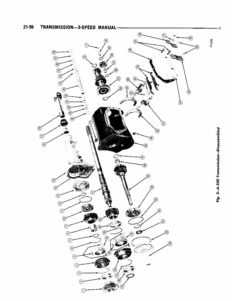
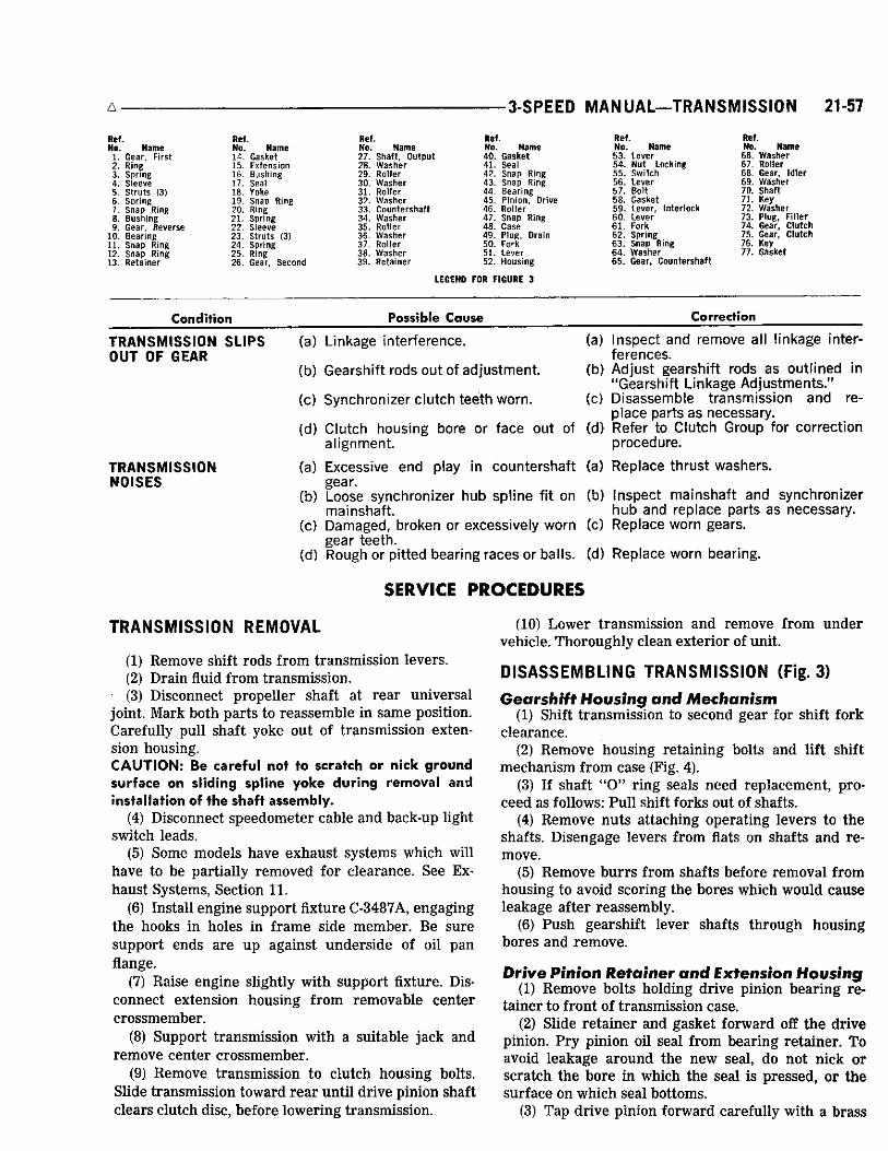
3-SPEED MANUAL—TRANSMISSION 21-57
Ref. No. Name
1. Gear, F i rst 2. Ring 3. Spring 4. Sleeve 5. Struts (3) 6. Spring 7. Snap Ring 8. Bushing 9. Gear, Reverse
10. Bearing 11. Snap Ring 12. Snap Ring 13. Retainer
Ref. No. Name 14. Gasket 15. Extension 16. Bushing 17. Seal 18. Yoke 19. Snap Ring 20. Ring
Spring 22. Sleeve 23. Struts (3) 24. Spring 25. Ring 26. Gear, Second
21
Ref. No. Name 27. Shaft , Output 28. Washer 29. Roller 30. Washer 31. Roller 32. Washer 33. Countershaft 34. Washer 35. Roller 36. Washer 37. Roller 38. Washer 39. Retainer
Ref. No. Name 40 . Gasket 41. Seal 42 . Snap Ring 43. Snap Ring 44. Bearing 45 . Pinion, Drive 46. Roller 47. Snap Ring 48. Case 49 . Plug, Drain 50. Fork 51. Lever 52. Housing
Ref. No. Name 5 3 . Lever 54 . Nut Locking 5 5 . Switch 56. Lever 5 7 . Bolt 58 . Gasket 59 . Lever, Interlock 6 0 . Lever 6 1 . Fork 6 2 . Spring 6 3 . Snap Ring 6 4 . Washer 6 5 . Gear, Countershaft
Ref. No. Name
66. Washer 67. Roller 68. Gear, Idler 69. Washer 70. Shaft 71. Key 72. Washer 73. Plug, F i l le r 74. Gear, Clutch 75. Gear, Clutch 76. Key 77. Gasket
LEGEND FOR FIGURE 3
Condition Possible Cause Correction
T R A N S M I S S I O N S L I P S OUT OF GEAR
T R A N S M I S S I O N N O I S E S
(a) Linkage interference. (a)
(b) Gearshift rods out of adjustment. (b)
(c) Synchronizer c lutch teeth worn. (c)
Inspect and remove all linkage interferences. Adjust gearshift rods as outlined in "Gearshif t Linkage Adjustments." D isassemble transmission and replace parts as necessary. Refer to Clutch Group for correction procedure.
(d) Clutch housing bore or face out of (d) alignment.
(a) Excess ive end play in countershaft (a) Replace thrust washers, gear.
(b) Loose synchronizer hub spl ine fit on (b) mainshaft.
(c) Damaged, broken or excessively worn (c) gear teeth.
(d) Rough or pitted bearing races or balls, (d) Replace worn bearing.
Inspect mainshaft and synchronizer hub and replace parts as necessary . Replace worn gears.
SERVICE PROCEDURES
TRANSMISSION REMOVAL
(1) Remove shift rods f rom transmission levers . (2) Dra in fluid f rom transmission. (3) Disconnect propel ler shaft at rear un iversa l
joint. Mark both parts to reassemble in same position. Care fu l ly pul l shaft yoke out of t ransmission extension housing. CAUTION: Be careful not to scratch or nick ground surface on sliding spline yoke during removal and installation of the shaft assembly.
(4) Disconnect speedometer cable and back-up light switch leads.
(5) Some models have exhaust systems which wi l l have to be part ial ly removed for c learance. See E x haust Systems, Section 11.
(6) Instal l engine support f ixture C-3487A, engaging the hooks in holes in f rame side member. B e sure support ends are up against underside of oil pan flange.
(7) Ra ise engine slightly wi th support fixture. Disconnect extension housing f rom removable center crossmember .
(8) Support t ransmission wi th a suitable j a c k and remove center crossmember .
(9) Remove transmission to c lutch housing bolts. Sl ide t ransmission toward r e a r unt i l dr ive pinion shaft c lears c lutch disc, before lower ing t ransmission.
(10) L o w e r t ransmission and remove f rom under vehicle . Thoroughly c lean exter ior of unit.
DISASSEMBLING TRANSMISSION (Fig. 3)
Gearshift Housing and Mechanism (1) Shift t ransmission to second gear for shift fork
c learance. (2) Remove housing retaining bolts and lift shift
mechan ism f rom case (Fig. 4). (3) If shaft " 0 " r ing seals need replacement , pro
ceed as follows: P u l l shift forks out of shafts. (4) Remove nuts attaching operating levers to the
shafts. Disengage levers f rom flats on shafts and remove.
(5) Remove b u r r s f rom shafts before removal f rom housing to avoid scoring the bores which would cause leakage after reassembly.
(6) P u s h gearshift lever shafts through housing bores and remove.
Drive Pinion Retainer and Extension Housing (1) Remove bolts holding dr ive pinion bear ing re
tainer to front of t ransmission case. (2) Sl ide re ta iner and gasket forward off the dr ive
pinion. P r y pinion oil seal f rom bear ing retainer . T o avoid leakage around the new seal , do not n ick or scra tch the bore in which the seal is pressed, or the sur face on w h i c h seal bottoms.
(3) Tap dr ive pinion forward careful ly wi th a brass
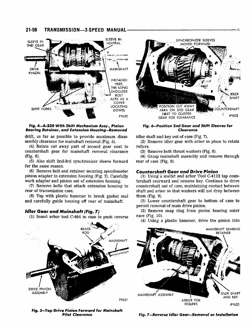
21-58 TRANSMISSION—3-SPEED MANUAL-
SLEEVE IN Hf^"'? 2ND GEAR N jT^
SLEEVE IN NEUTRAL
\
SHIFT FORKS
MAINSHAFT
INSTALLED \ HERE, \ THE LONG \SHOULDER
BOLT ACTS AS A
COVER LOCATING
DOWEL
PY630
F i g . 4-A-230 Wi th Shift Mechanism Ass/. , P in ion B e a r i n g Hef ainer, and Extension Housing—Removed dr i f t , as far as possible to provide max imum disassembly clearance for mainshaft removal (Fig. 5).
(4) Rotate cut away part of second gear next to countershaft gear for mainshaft removal clearance (Fig. 6).
(5) Also shift 2nd-3rd synchronizer sleeve forward for the same reason.
(6) Remove bolt and retainer securing speedometer pinion adapter i n extension housing (Fig. 2). Carefully work adapter and pinion out of extension housing.
(7) Remove bolts that attach extension housing to rear of transmission case.
(8) Tap w i th plastic hammer to break gasket seal and carefully guide housing off rear of mainshaft.
Idler Gear and Mainshaft (Fig. 7) (1) Insert arbor tool C-464 i n case to push reverse
BRASS ROD
MAINSHAFT
DRIVE PINION ASSEMBLY
PY631
F ig . 5—Tap Drive Pinion Forward for Mainshaft Pilot Clearance
SYNCHRONIZER SLEEVES MOVED FORWARD
POSITION CUT AWAY AREA ON 2ND GEAR \ * '
NEXT TO CLUSTER GEAR FOR CLEARANCE
\ IDLER SHAFT
\ COUNTERSHAFT
PY632
Fig. 6--Position 2nd Bear and Shift Sleeves for Clearance
id ler shaft and key out of case (Fig. 7). (2) Remove id ler gear wi th arbor i n place to retain
rollers. (3) Remove both thrust washers (Fig. 8). (4) Grasp mainshaft assembly and remove through
rear of case (Fig. 8).
Countershaft Gear and Drive Pinion (1) Using a mallet and arbor Tool €-4112 tap coun
tershaft rearward and remove key. Continue to drive countershaft out of case, maintaining contact between shaft and arbor so that washers w i l l not drop between them (Fig. 9).
(2) Lower countershaft gear to bottom of case to permit removal of main drive pinion.
(3) Remove snap r ing f r om pinion bearing outer race (Fig. 10).
(4) Using a plastic hammer, drive the pinion into
MAINSHAFT BEARING RETAINER
MAINSHAFT ASSEMBLY ARBOR FOR
ROLLERS
IDLER SHAFT AND KEY
PY633
Fig. 7—Reverse Idler Gear—Removal or Installation

A 3-SPEED MANUAL—TRANSMISSION 21-59
DRIVE PINION %, . •P GEAR •PBBBI
REVERSE IDLER GEAR THRUST WASHERS
* COUNTERSHAFT GEAR
P Y 6 3 4
Fig. 8—Mainshaft Assembly—Removal or Installation
case and remove through r e a r (F ig . 11). (5) If bear ing is to be replaced, remove snap r ing
and press bearing off the pinion gear shaft (Fig. 12). (6) L i f t countershaft gear and arbor assembly out
through rear of case (F ig . 13).
Mainshaft Disassembly
(1) Remove the snap r ing f rom front end of main-shaft which retains the 2nd-3rd synchronizer c lutch gear (Fig. 14).
(2) Sl ide the 2nd-3rd synchronizer assembly off end of mainshaft along with the 2nd gear stop r ing (Fig. 15).
(3) Remove 2nd gear f rom mainshaft (F ig. 16). (4) Spread snap r ing in mainshaft bear ing retainer
to disengage it f rom bear ing groove and slide retainer off the bearing race (Fig. 17).
(5) Remove snap r ing secur ing bearing to mainshaft (Fig. 18).
(6) Set up parts in arbor press to force bear ing off
COUNTERSHAFT
, ^ ^ ^ ^ ^ ^ ^ ^ ^ ^ ^ ^ ^ ^ ^ B ^ B
ARBOR FOR ROLLERS
COUNTERSHAFT GEAR
Fig. 9—Countershaft Removal
PY635
SNAP RING
BEARING OUTER RACE s
"TP V 4
# 4
^ ^ ^ ^ ^ PY636 / ' • * M I .
Fig. 10—Snap Ring on Pinion Gear Bearing—Removal
¥t •* x 4''' *
P Y 6 3 7
I COUNTERSHAFT GEAR AND ARBOR ASSEMBLY LYING I N B O T T O M OF CASE
Fig. 11—Drive Pinion and Bearing Assembly-Removal or Installation
SNAP RING PLIERS
DRIVE PINION GEAR SHAFT
\ > $
P Y 6 4 1
Fig. 12—Snap Ring, Pinion Shaft tf© / i © ® r a D g - . Removal or fnsfaffafion

21-60 T R A N S M I S S I O N — 3 - S P E E D M A N U A L • • - — — A
RET AIN ER MOUNTING BOLT HOLES ( 4 ) M : ^ ,
HOLE FOR PINION BEARING RETAINER DRAIN PY638
Fig. 13—Countershaft Gear and Arbor Assembly-Removal or Installation
SNAP RING PLIERS
PY643
Fig. 14—Snap Ring—2ficf-3rd S y n c h r o n i z e r Clutch Gear to Mainshaft—Removal or Installation
2ND GEAR STOP RING
S T O P RING LUG
2ND-3RD SYNCHRONIZER ASSEMBLY PY644
Fig. 75—2nd-3rd Synchronizer Assembly and Stop Ring—Removal or Installation
THRUST FLANGE O N MAINSHAFT
SECOND GEAR
FIRST GEAR
PY645
Fig. 16—2nd Gear—Removal or Installation
mainshaft . B y support ing front side of reverse gear it can push the bear ing off shaft as pressure is applied to shaft (Fig. 19). W h e n bear ing c lears shaft, don't let parts drop through.
(7) Remove f rom press and slip off the end of shaft, the mainshaft bear ing and reverse gear (Fig. 20).
(8) Remove f rom mainshaft the snap r ing which retains the ls t -Reverse synchronizer c lutch gear (Fig. 21).
(9) Sl ide ls t -Reverse synchronizer assembly off
SNAP RING PLIERS
MAINSHAFT BEARING RETAINER
GROOVE IN BEARING RACE
PY646
Fig 17—Snap Ring Spread, to Remove or Install Retainer on Mainshaft Bearing
SNAP RING PLIERS
MAINSHAFT BEARING
JsSP
REVERSE GEAR
SNAP RING
PY647
Fig. IS—Snap Ring—Mainshaft Bearing to Shaft— Removal or Installation

3 - SPEED MANUAL—TRANSMISSION 2 1 - 6 1
SUPPORT MAINSHAFT T O AVOID F A L L
W H E N C L E A R O F * B E A R I N G
*:
• PRESS R A M
• mm
mm
SNAP RING O K MAINSHAFT , . -t
SNAP RING
4&4
1ST-REVERSE SYNCHRONIZER
A S S E M B L Y
'1ST G E A R
PY654
Fig. 21 — S n a p Ulng— l s t - R e v e r s e S y n c h r o n i z e r dutch Gear—Removal or Installation
S T O P R I N G
PLATES SUPPORTING REVERSE GEAR WHICH
SLIDES AGAINST BEARING
•HI m
PRESS BED
^ i PY651 ^
Fig. 19—Using Press to Remove Mainshaft Bearing
splines and remove f rom mainshaft (F ig. 22). (10) Remove 1st gear and its stop r ing f rom main-
shaft (Fig. 23).
CLEANING AND INSPECTION
Clean t ransmission case thoroughly, us ing a suitable solvent, dry wi th compresesd air . Inspect case for cracks , str ipped threads in various bolt holes and machined mat ing sur faces for burrs , n icks or any condition that would render the case unfit for fur ther service. T h e front mat ing surface should be smooth; if any bur rs are present , dress them off with a fine mi l l file. I f threads are str ipped, instal l Hel icoi l inserts.
\ 1ST GEAR
MAINSHAFT 1ST-REVERSE
SYNCHRONIZER ASSEMBLY PY655
Fig. 22— I sf-Reverse Synchronizer Assembly-Removal or Installation
Ball Bearings W a s h bal l bearings, us ing a c lean solvent and blow
dry with compressed air.
CAUTION: Do not spin bearings with air pressure; turn slowly by hand. Spinning unlubricated bearings may cause damage to races and balls.
B e sure bal l bearings are c lean, then lubricate them with l ight grade engine oil. Inspect bearings for pitting. T h i s can best be determined by slowly turning outer race by hand. Measure fit of bear ings on their respect ive shafts.
/ MAINSHAFT
BEARING
GROOVE FOR 1ST GEAR BEARING SNAP RING
\
REVERSE GEAR
\ NO STOP RING ON REVERSE
SIDE OF SYNCHRONIZER
PY653
Fig. 20—Reverse Gear and Mainshaft Bearing-Removal or Installation
STOP RING'
THRUST FLANGE BETWEEN 1ST AND 2ND GEARS
/
H \
CLUTCH GEAR SPLINES AND SNAP RING GROOVES
1ST GEAR PY656
Fig. 23—1st Gear and Stop Ring—Removal or Installation

21-62 TRANSMISSION—3-SPEED MANUAL A
Needle Type Bearing Rollers and Spacers Inspect a l l bear ing rol lers for l a t spots or br inel -
l ing. Inspect a l l bear ing rol ler spacers for signs of wear or gall ing. Instal l new parts as required.
Gears Inspect gear spl ines on synchronizer c lutch gears
and stop r ings. I f there is evidence of chipping or excessively worn teeth, instal l new parts at reassembly. B e sure c lutch sleeve sl ides easi ly on the c lutch gear. Inspect countershaft gear and a l l gear teeth for chipped or broken teeth, or showing signs of excessive wear . S m a l l n icks or bur rs must be stoned off.
Inspect teeth on main dr ive pinion. I f excessively worn, broken or chipped, a new pinion should be instal led. I f the oil seal contact area on drive pinion shaft is pitted, rusted or scratched, a new pinion is recommended for best seal l ife.
Synchronizer Stop Rings Inspect stop r ings for c racks and wear . I f r ings are
c racked or show signs of extreme wear on threaded bore, instal l new r ings at reassembly. T e s t new r ings for good fit on gear cones with m in imum wobble.
Mainshaft Inspect mainshaft gear and bear ing mat ing sur
faces. I f gear contact sur faces show signs of gal l ing or are excessive ly worn, a new mainshaft should be instal led.
Inspect snap r ing grooves for burred edges. I f rough or bur red , remove condit ion us ing a fine file or crocus cloth. Inspect synchronizer c lutch gear spl ines on shaft for burrs .
ASSEMBLING TRANSMISSION
Countershaft Gear (1) Sl ide assembly arbor, Tool C-4112, into counter
shaft gear. (2) Sl ide one rol ler thrust washer over arbor a n d
into gear, fol lowed by 22 Greased Rol le rs (F ig. 24). (3) Repeat Step 2, adding one rol ler thrust w a s h e r
on end. (4) Repeat Steps 2 and 3 at other end of counter
shaft gear. (Total of 88 Ro l le rs and 6 thrust washers) . (5) P lace greased front thrust washer on arbor
against gear wi th tangs forward. (6) Coat r e a r thrust washer with heavy grease and
st ick it in place in the transmission case, wi th tangs rearward .
(7) Care fu l ly place countershaft gear assembly in position in bottom of t ransmission case (F ig. 13). Do not finish installation with countershaft and key until drive pinion is instal led.
Pinion Gear (8) P r e s s new bear ing on pinion with snap r ing
COUNTERSHAFT GEAR ROLLER
ASSEMBLY ARBOR SPECIAL TOOL
. 4 -
^OL.:R THRUST WASHER
-GEAR THRUST WASHER P Y 6 4 9
Fig. 24—Countershaft Gear—Roller Bearing Assembly
groove forward. Instal l snap r ing on shaft (Fig. 12). (9) Instal l 15 rol lers and retaining r ing in gear (Fig.
25) . (10) Instal l dr ive pinion and bear ing assembly into
case (F ig . 11). (11) Now finish installation of countershaft gear
assembly by positioning it and the thrust washers so that the countershaft can be tapped into position (Fig. 26) . Be careful to keep the arbor in contact with the countershaft to avoid parts dropping out of position and blocking the installation. Insta l l key in countershaft as installation is finished.
(12) Care fu l ly tap drive pinion forward to provide m a x i m u m clearance for mainshaft instal lat ion (Fig. 5).
Mainshaft (Fig. 27) (13) Sub assemble the synchronizer parts in the
order shown in (Figs. 28, 29 and 30) as follows: P lace a stop r ing flat on the bench fol lowed by the c lutch gear and sleeve. Drop the struts in their slots and snap in a strut spr ing placing the tang inside one strut. T u r n the assembly over on the stop r ing and instal l second strut spr ing with tang in a different strut.
(14) Sl ide 1st gear and stop r ing over rear end of mainshaft and against flange wh ich separates 1st and 2nd gears (Fig. 23).
RETAINING RING
MAINSHAFT PILOT BEARING ROLLER
P Y 6 4 0 t ' "f .
Fig. 25—Installing Rollers in Drive Pinion Gear

A • 3-SPEED MANUAL—TRANSMISSION 21-63
: COUNTERSHAFT
ASSEMBLY ARBOR SPECIAL TOOL
PY657
Fig. 26—Countershaft—Installation
(15) Sl ide ls t -Reverse synchronizer assembly over mainshaft , indexing the hub slots to 1st gear stop r ing lugs (Fig. "22).
(16) Instal l c lutch gear snap r ing on mainshaft (Fig. 21).
(17) Sl ide reverse gear and mainshaft bear ing in place and take to press, to force bear ing on shaft (Fig. 20).
(18) Support inner race of bear ing and press shaft through to shoulder (Fig. 31). Be sure snap ring groove on outer race is forward.
(19) Instal l bear ing retaining snap r ing on main-shaft (Fig. 18).
(20) Spread snap r ing in mainshaft bear ing retainer groove and slide it over the bear ing. B e sure snap r ing seats in bear ing groove (Fig. 17).
(21) P lace second gear over front of mainshaft with thrust surface against flange (Fig. 16).
(22) Instal l properly indexed stop r ing and 2nd-3rd synchronizer assembly against second gear (Fig. 15).
M A I N S H A F T B E A R I N G S N A P RING-BEARING R E T A I N E R - TO R E T A I N E R
FIRST G E A : ;
2ND-3RO \ SYNCHRONIZED SL~£VE "
STOP R I N G
I . - , -REVERSE S Y N C " I O N I Z E R SIfEVE
S E C O N D GEAR
S " 0 ? T,KG
CLUTCH GEAR (POSITION LONG HUB FORWARD)
\
S T O P Rl N G \
SNAP RING
\
- STRUTS
STRUT SPRINGS (2)
CLUTCH SLEEVE
PY203
Fig. 28—1 st-Reverse Synchronizer—Disassembled
(23) Instal l 2nd-3rd c lutch gear snap r ing on shaft (F ig. 14).
(24) Move 2nd-3rd synchronizer sleeve forward as far as pract ica l ( l imited by need to retain struts i n place) and insta l l f ront stop r ing (coated wi th grease to hold it in position) inside sleeve with lugs indexed to struts.
(25) Rotate cut out on second gear so it is toward countershaft gear for c learance (F ig . 6).
(26) Now slowly insert mainshaft assembly into case (Fig. 8) t i l t ing it as required to c lear c luster gears and finally enter ing the pilot ro l lers in the dr ive pinion gear.
I f everything is in proper position the bear ing retainer wi l l bottom to the case without force. If not, check to see if a strut , pinion rol ler , or stop r ing is out of position.
Reverse Idler Gear (27) P lace assembly arbor, Tool C-464 into id ler
gear along with 22 greased rol lers (Fig. 32). (28) Position reverse id ler thrust washers in case
with grease to reta in them. (29) Now position reverse id ler gear with arbor and
CLUTCH GEAR SLEEVE^ STOP RINGs
STRUT SPRINGS ( 2 \ v
STOP R I N G
PY642
Ufa*
CLUTCH GEAR
FORWARD
*SNAP RING LUG-STOP RING TO CLUTCH GEAR PY202
Fig. 27—Mainshaft Assembled Fig. 29—2nd-3rd Synchronizer—Disassembled
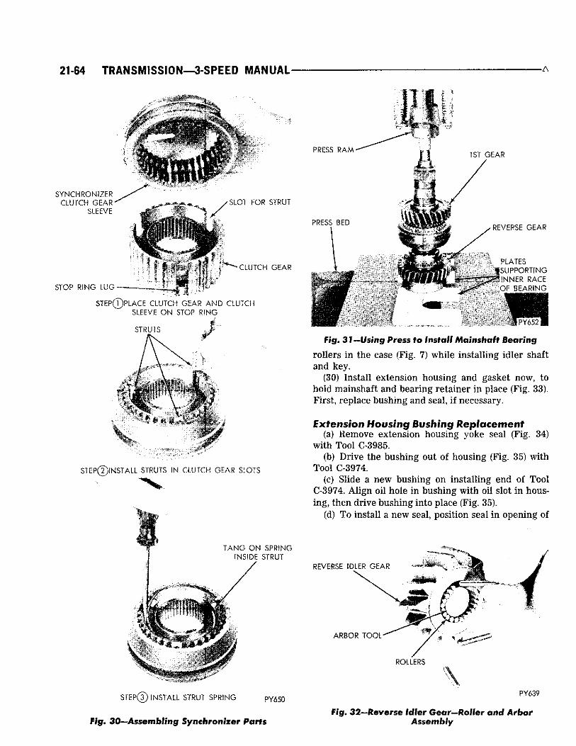
21-64 TRANSMISSION—3-SPEED MANUAL • A
PRESS RAM* 1 S T G E A R
SYNCHRONIZER CLUTCH G E A R ^
SLEEVE S L O T F O R S T R U T
"CLUTCH GEAR
STOP RING LUG-
STEP®PLACE CLUTCr" GEAR AND CLUTCH SLEEVE O N S T O P RING
STRUTS X
STEP@INSTALL STRUTS IH CLUTCH GEAR SLOTS
PRBS O J D
4*
S
REVERSE GEAR
PLATES SUPPORTING
* INNER RACE OF BEARING
••dH 11^^ I fhgo 3 Ji —Using Press to Install Mainshaft Bearing
rol lers in the case (F ig. 7) whi le instal l ing id ler shaft and key.
(30) Insta l l extension housing and gasket now, to hold mainshaft and bear ing reta iner in place (Fig. 33). F i r s t , replace bushing and seal , if necessary.
Extension Housing Bushing Replacement (a) Remove extension housing yoke seal (Fig. 34)
with Tool C-3985. (b) Dr ive the bushing out of housing (Fig. 35) with
Tool C-3974. (c) Sl ide a new bushing on instal l ing end of Tool
C-3974. A l i g n oil hole in bushing wi th oil slot in housing, then drive bushing into place (Fig. 35).
(d) T o instal l a new seal , position seal i n opening of
TANG ON SPRING INSIDE STRUT
/
REVERSE IDLER GEAR
ARBOR TOOL
ROLLERS
STEP® INSTALL STRUT SPRING P Y 650
Fig. 30—Assembling Synchronizer Parts
PY639
Fig. 32—Reverse Idler Gear—Roller and Arbor Assembly

A 3-SPEED MANUAL—TRANSMISSION 21-65
VENT PASSAGE
. . . . . — L O C A T I N G KEYWAY f \ FOR BEARING
?Ss2^^ § RETAINER
-TOOL
* - 4 v | | EXTENSION HOUSING - "x > i f TO TRANSMISSION
* * AMOUNTING BOLT HOLES
:. • • X ^ 0 0 ^ ^ ' PY629
Fig. 33—Extension Housing—front View
extension housing and dr ive it into housing with Tool C-3972 (Fig. 36).
Drive P i n i o n B e a r i n g Retainer (31) Instal l the outer snap r ing on the drive pinion
bearing and tap the assembly back unt i l the snap r ing contacts case.
(32) Us ing Tool C-3789 (F ig . 37), instal l a new oil seal in retainer bore. Posit ion main drive pinion bearing retainer and gasket on front of case. Coat threads with seal ing compound, then instal l attaching bolts and tighten to 30 foot-pounds (Fig. 2).
Gearshift Mechanism and Housing (fig. 38) (33) I f removed, place the two inter lock levers on
TOOL \
f SEAL
NN361
Fig. 34—Removing Extension Housing Seal
TOOL INSTALLING BUSHING
BUSH'NG TOOL
\ INSTALLING END
* REMOVING END
NU43
NN125
Fig. 36—Installing Extension Housing Seal
the pivot p in with the spr ing hangers offset toward each other so the spr ing w i l l instal l in a straight l ine, and secure with " E " cl ip on Pivot pin.
(34) G r e a s e and instal l new " 0 " r ing oi l seals on both shift shafts. Grease housing bores and p u s h e a c h shaft into its proper bore.
(35) W i t h pl iers instal l the spr ing on inter lock l ever hangers .
(36) Rotate each shift shaft fork bore, to neutra l position (straight up) and insta l l shift forks through bores and under both inter lock levers.
Install Gearshift Mechanism (37) Posit ion the 2nd-3rd Synchronizer sleeve in
t ransmission to rear (in 2nd gear). Posit ion the ls t -reverse synchronizer sleeve to middle of t ravel (in neutral ) (Fig. 4). P lace the shift forks in the gearshift mechan ism in the same positions.
(38) Insta l l gasket and gearshift mechan ism on transmission us ing special shoulder bolts. One bolt has an extra long shoulder wh ich enters the t ransmission case acting as a locating dowel pin. T h i s hole is at center r e a r of case (Fig. 4). T ighten bolts evenly to 15 foot-pounds.
(39) Insta l l speedometer dr ive pinion gear and adapter being sure range number , stamped on outside of adapter, represent ing number of teeth on gear, is in 6 " 0 " clock position (Fig. 40).
TRANSMISSION INSTALLATION
Place a smal l amount of Mult i -Purpose lubr icant around inner end of pinion shaft pilot bushing in flywhee l and on pinion bear ing retainer pilot, for c lu tch
DRIVE PINION BEARING RETAINER
\ SEAL I N S T A L L I N G TOOL
N U 4 4
fig. 35-Replacing Bushing in Extension Housing Fig. 37—Installing Seal in Drive Pinion
Bearing Retainer

21-66 TRANSMISSION—3 -SPEED MANUAL A
SHIFT LEVER (TYPICAL)"^.
INTERLOCK LEVERS
2ND-3RD SHIFT SHAFT PY648
Fig. 38—Gearshift Mechanism and Housing-* Disassembled
re lease sleeve. Do not lubricate end ©f pinion shaft, clutch disc splines or clutch release levers.
(1) W i t h t ransmission on a suitable jack, slide assembly under vehic le .
(2) Ra ise t ransmission u n t i l drive pinion is centered in c lu tch housing bore.
(3) Ro l l t ransmission slowly forward unt i l p inion shaft enters c lutch disc. T u r n pinion shaft u n t i l spl ines are a l i g n e d , then w o r k t r a n s m i s s i o n f o r w a r d u n t i l seated against c lutch housing. Do not allow trans-
Fig . 40—Speedometer Pinion and Adapter— Installed in Extension Housing
mission to "hang" after pinion shaft has entered the clutch disc. •
(4) Insta l l t ransmission to c lutch housing bolts and tighten to 50 foot-pounds.
(5) Us ing a pointed drift, al ign crossmember bolt holes, then instal l attaching bolts. T ighten to 75 footpounds (F ig . 39).
(6) Remove engine support fixture and disengage hooks f rom holes in the f rame side ra i ls . Insta l l extension housing to rear engine mount bolts and tighten to 40 foot-pounds. E n g i n e mount to center cross-member bolt and nut, loose assembled to this point, should now be torqued to 50 foot-pounds.
(7) Re fe r r ing to "Gearshi f t L i n k a g e Ad jus tment" , conenct shift control rods to t ransmission levers and connect speedometer cable.
NU48A
Fig. 39—Center Crossmember and Hear Engine Mount
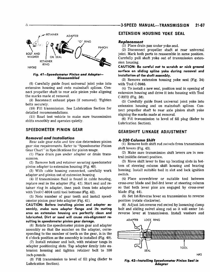
3-SPEED MANUAL—TRANSMISSION 21-67
- R E T A I N E R ADAPTER
" O M R I N G
BOLT AND WASHER
P I N I O N
O I L S E A L
RETAINER RING
NN362
Fig. 41 —Speedometer Pinion and Adapter-Disassembled
(8) Care fu l ly guide front universa l joint yoke into extension housing and onto mainshaft spl ines. C o n nect propel ler shaft to rear axle pinion yoke al igning the m a r k s made at removal .
(9) Reconnect exhaust pipes (if removed). T ighten bolts secure ly .
(10) F i l l t ransmission. See Lubr icat ion Section for detailed recommendat ions.
(11) Road test vehicle to make sure t ransmission shifts smoothly and operates quietly.
SPEEDOMETER PINION GEAR
Removal and Installation R e a r axle gear ratio and tire size determines pinion
gear size requirements. Re fe r to "Speedometer P in ion Gear C h a r t " in Specifications for pinion usage.
(1) P lace dra in pan under adapter or dra in transmission.
(2) Remove bolt and reta iner secur ing speedometer pinion adapter to extension housing (Fig. 40).
(3) Wi th cable housing connected, careful ly work adapter and pinion out of extension housing.
(4) If t ransmission fluid is found in cable housing, replace seal in the adapter (Fig. 41). Start seal and retainer r ing in adapter, then push them into adapter with Tool C-4004 unti l tool bottoms (Fig. 42).
(5) Note number of gear teeth and instal l speedometer pinion gear into adapter (Fig. 41). C A U T I O N : Before install ing pinion and adapter assembly, make sure adapter flange and its mating area on extension housing are perfectly clean and lubricated. Dirt or sand will cause mis-alignment resulting in speedometer pinion gear damage.
(6) Rotate the speedometer pinion gear and adapter assembly so that the number on the adapter, corresponding to the number of teeth on the gear, is in the 6 o'clock position as the assembly is instal led (Fig. 40).
(7) Insta l l re ta iner and bolt, with reta iner tangs in adapter posit ioning slots. T a p adapter f irmly into extension housing and tighten retainer bolt to 100 inch-pounds.
(8) F i l l t ransmission to level of fill p lug (Refer to Lubr ica t ion Section).
EXTENSION HOUSING YOKE SEAL
Replacement (1) P lace drain pan under yoke sea l . (2) Disconnect propel ler shaft at r e a r un iversa l
joint. Mark both parts to reassemble i n same position. Care fu l ly pul l shaft yoke out of t ransmiss ion extension housing. CAUTION: Be careful not to scratch or nick ground surface on sliding spline yoke during removal and installation of the shaft assembly.
(3) Remove extension housing yoke sea l (Fig. 34) with Tool C-3985.
(4) T o instal l a new seal , position seal in opening of extension housing and dr ive it into housing with Tool C-3072 (Fig. 36).
(5) Care fu l ly guide front un iversa l joint yoke into extension housing and on mainshaft spl ines. Connect propel ler shaft to rear axle pinion shaft yoke al igning the m a r k s made at removal .
(6) F i l l t ransmission to level of fill p lug (Refer to Lubr icat ion Section).
GEARSHIFT LINKAGE ADJUSTMENT
A-230 Column Shift (1) Remove both shift rod swivels f rom transmission
shift levers (Fig. 43). (2) Make sure t ransmission shift levers are in neu
t ra l (middle detent) position. (3) Move shift lever to l ine up locating slots in bot
tom of steer ing column shift housing and bearing housing. Instal l suitable tool in slot and lock ignition switch.
(4) P lace screwdr iver or suitable tool between cross-over blade and 2nd-3rd lever at steer ing column so that both lever pins are engaged by cross-over blade (Fig. 44).
(5) Set ls t -Reverse lever on transmission to reverse position (rotate clockwise).
(6) A d j u s t ls t - reverse rod swivel by loosening clamp bolt and sl iding swivel along rod so it wi l l enter ls t -reverse lever at t ransmission. Insta l l washers and
A D A P T E R L O C K R I N G
T O O L S E A L
NP2
Fig. 42—Installing Speedometer Pinion Seal in Adapter

21-68 TRANSMISSION—3-SPEED MANUAL
Fig. 43—Column
clip. T ighten swive l bolt to 100 inch-pounds. (7) Remove gearshif t housing locating tool, un lock
ignit ion swi tch and shift co lumn lever to neutra l position.
(8) A d j u s t 2nd-3rd rod swivel by loosening c lamp bolt and sl id ing swive l along rod so it w i l l enter 2nd-3rd lever at t ransmission. Insta l l washers and cl ip. T ighten swive l bolt to 100 inch-pounds.
(9) Remove tool f rom cross-over blade at steer ing co lumn and shift through al l gears to check adjustment and cross-over smoothness.
(10) C h e c k for proper operation of steer ing co lumn lock in reverse and second gear positions. W i t h proper l inkage adjustment , co lumn should lock in reverse position and should not lock in second position.
I f f Linkage CROSS-OVER BLADE IN NEUTRAL
F i g . 44—Holding Crossover Blade in Neutral Position

A SPECIFICATIONS 21-81
SPECIFICATIONS 3-SPEED T R A N S M I S S I O N
(A-230 ALL SYNCHRONIZED)
Engine Displacement (Cu. in.)
Gear Ratio First . . . Second Third Reverse
Downshift Speed Limits 3rd to 2nd 2nd to 1st
Lubricant Capacity ... U.S.
Type
Gear Type . . . Tolerances
Clutch Housing Face Squareness Clutch Housing Bore Run-Out.
SPEEDOMETER PINION G E A R CHART
383
2.55 1.49 1.00 3.34
45 to 15 M.P.H. 25 to 0 M.P.H.
Pints IMP. Pints 5 4-1/4 Auto Trans. Fluid AQ-ATF Suffix "A"
or "Dexron" Helical
.006 Max.
.008 Max.
ALL TRANSMISSIONS NUMBER OF TEETH ON PINION GEAR LISTED UNDER EACH AXLE RATIO
Tire Size
Tire Size 2.45:1 2.71:1 2.76:1 2.93:1 2.94:1 3.23:1 3.54:1 3.55:1 3.91:1 4.10:1
F78 x 15 29 31 35 7.75 x 15 24 27 27 29 29 32 35 38 8.25 x 15 24 26 27 28 28 31 34 38
G78 x 15 26 26 28 31 34 8.55 x 15 26 26 28 31 34 8.85 x 15 25 26 27 30 33 9.15 x 15 25 26 27 30 33
H78 x 15 25 26 27 30 33 J78 x 15 25 26 27 30 33
G70 x 15 26 27 29 31 35 E60 x 15 29 34 37 37 41 43 F60 x 15 25 28 28 30 33 36 40 42
TORQUEFLITE TRANSMISSION TRANSMISSION MODEL T Y P E
T O R Q U E C O N V E R T E R Diameter (Std.)
(High Pert.)
O IL C A P A C I T Y — T R A N S M I S S I O N AND T O R Q U E C O N V E R T E R . . . U s e Automatic Transmiss ion Fluid labeled Type AQ-ATF, Suf-
A-727-B Automatic Three
Speed with Torque Converter
11-3/4" 10-3/4"
U.S. Measure
fix "A" or "Dexron" (Std.) 19 pts. Imp. Meas.
16 pts. (High Perf.) U.S. 16-1/2 pts.
Imp. Meas. 13-1/2 pts.
COOLING METHOD Water-Heat Exchanger
L U B R I C A T I O N Pump (Rotor Type) C L U T C H E S
Number of Front Clutch P la tes . 4

21-70 TIGHTENING REFERENCE A
Number of Front D iscs . . . . 4 Number of Rear Clutch P lates . 3 Number of Rear D iscs . . . . . . . . 4
G E A R RATIOS 1— First 2.45 to 1 2 — Second 1.45 to 1 D—Third 1 to 1 R _ R e v e r s e 2.20 to 1
P U M P C L E A R A N C E S Outer Rotor to C a s e Bore .004 to .008 inch Outer to Inner Tip .005 to .010 inch End Clearance—Rotors . . . .0015 to .003 inch
Planetary Assy. End Play 010 to .037 inch
Drive Train End Play .037 to .084 inch C L U T C H P L A T E C L E A R A N C E
Front Clutch 383 & 440 C u . In. Engine . . . . .024 to .125 inch 440 High. Perf. Engine 066 to .123 inch
Rear Clutch .025 to .045 inch
SNAP RINGS Front and Rear C lu tches Rear Snap Ring (Selective) . . . .060 to .062 inch
.074 to .076 inch
.088 to .090 inch Output Shaft (Forward End) . . .048 to .052 inch
.055 to .059 inch
.062 to .066 inch
BAND A D J U S T M E N T S Kickdown Band (Front) 2 T u r n s * Low-Reverse Band (Internal) . . 2 T u r n s *
T H R U S T W A S H E R S Reaction Shaf t Support to
Front Clutch Retainer (Selective) 061 to .063 inch
(Green) .084 to .086 inch
(Red) .102 to .104 inch
(Yellow) Output Shaft to Input Shaft . . . .062 to .064 inch Driving Shel l Thrust P l a t e -
Steel (1) 034 to .036 inch Rear Planetary Gear to Driving
Shel l • .062 to .064 inch Front Planetary Gear to Annu
lus Gear Support 062 to .064 inch Front Annulus Gear to
Driving Shel l 062 to .064 inch Front Clutch to Rear Clutch . . .061 to .063 inch Rear Planetary Gear to
Annulus Gear 034 to .036 inch
* Backed off from 72 inch-pounds.
T I G H T E N I N G
Foot Pounds
Manual A-230 3-Speed Back Up Light Swi tch . . . . . . . . . . . . . . . . 15 Extension Housing Bolts . . . . . . . . . . . . . 50 Drive Pinion Bearing Retainer Bolts 30
Pounds Foot Inch
Torquefiite A-727-B Cooler Line Fitting . . — 110 Cooler Line Nut — 85 Converter Drain Plug . . . . . . . . . . . . . — 110 Converter Drive Plate to Crankshaft
Bolt 55 — Converter Drive Plate to Torque
Converter Bolt — 270 Extension Housing to Transmiss ion
C a s e Bolt 24 — Extension Housing to Insulator
Mounting Bolt 40 — Extension Hous ing—Crossmember to
Frame Bolt 75 — Governor Body to Support Bolt — 100 Kickdown Band Adjusting S c r e w
Lock Nut 29 — Kickdown Lever Shaft Plug — 150
R E F E R E N C E
Foot Pounds
Gearshift Operating Lever Nuts . 18 Transmiss ion to Clutch Housing Bolts . 50 Transmiss ion Cover Retaining Bolts 12 Transmiss ion Drain Plug 25
Pounds Foot Inch
Neutral Starter Switch 24 — Oil Pan Bolt — 150 Oil Pump Housing to Transmiss ion
Case Bolt — 175 Output Shaft Support Bolt — 150 Overrunning Clutch C a m S e t Screw . . . — 40 Pressure Tes t Take-off Plug — 75 Reaction Shaft Support to Oil
Pump Bolt — 160 Reverse Band Adjusting Screw
Lock Nut 35 — Speedometer Drive C lamp S c r e w — 100 Transmiss ion to Engine Bolt 28 — Valve Body Screw — 35 Valve Body to Transmiss ion
Case Bolt — 100