group 9 base of body repair - evoecu manual...welding 9-2 base of body repair welding welding...
TRANSCRIPT

9-1
GROUP 9
BASE OF BODY REPAIR
CONTENTS
WELDING. . . . . . . . . . . . . . . . . . . . . . 9-2WELDING . . . . . . . . . . . . . . . . . . . . . . . . . . 9-2ELECTRIC RESISTANCE SPOT WELDING . . . . . . . . . . . . . . . . . . . . . . . . . . 9-2GAS SHIELD ARC WELDING . . . . . . . . . . 9-8OTHER TYPES OF WELDING. . . . . . . . . . 9-11
BODY REPAIR. . . . . . . . . . . . . . . . . . 9-14STANDARD BODY REPAIR PROCEDURES. . . . . . . . . . . . . . . . . . . . . . 9-14THEFT PROTECTION . . . . . . . . . . . . . . . . 9-22ATTACHMENT OF SILENCERS . . . . . . . . 9-24POSITIONING DIMENSIONS FOR OPENINGS . . . . . . . . . . . . . . . . . . . . . . . . . 9-25
STANDARD PROCEDURES FOR SHEET METAL WORK . . . . . . . . . . . . . . . . . . . . . . 9-25USING A FRAME STRAIGHTENER . . . . . . 9-27FRAME REPAIR PROCEDURES . . . . . . . . 9-28NOTES REGARDING REPAIR WORK. . . . 9-30HEAT-WITHSTAND TEMPERATURES OF RESIN-PLASTIC PARTS . . . . . . . . . . . . . . 9-32HOW TO DISTINGUISH TYPES OF PLASTICS . . . . . . . . . . . . . . . . . . . . . . . . . . 9-35
CORROSION PROTECTION . . . . . . . 9-36ANTICORROSION TREATMENT AT THE FACTORY . . . . . . . . . . . . . . . . . . . . . . 9-36ANTICORROSION TREATMENT AT THE TIME OF BODY REPAIR WORK . . . . 9-39

WELDINGBASE OF BODY REPAIR9-2
WELDINGWELDING
M4090001000025Welding is the partial joining of two or more metals by deposition; the welding methods used for body maintenance and repair can be classified into the fol-lowing methods.
FUSION WELDINGFusion welding is a method of welding in which the weld connection is made by forming or supplying the weld metal at the part where the weld is to be made.
PRESSURE WELDINGPressure welding is a method of welding in which the weld connection is made by applying external pres-sure while the part where the weld is to be made is in a molten or semi-molten condition.
BRAZINGBrazing is a method of welding in which the weld connection is made by supplying a filler metal (which is molten at a temperature lower than the melting temperature of the base metal) at the place where the joining is to be made without melting the base metal itself.
ELECTRIC RESISTANCE SPOT WELDINGM4090002000017
Electric resistance spot welding is a method for fus-ing metal parts together. Two or three metal sheets are positioned between two copper-alloy electrode tips, and pressure and a large current are then applied, thus causing the contacting surfaces to heat up and fuse together because of the electric contact resistance.
ADVANTAGES OF ELECTRIC RESISTANCE SPOT WELDING
• Because the time required for welding at each point is brief, the work can be done quickly and at reduced cost.
• Because both metals are fused and pressure applied to make the weld, the strength and reli-ability are both high.
• Because the time required to make the welds is short, there is little occurrence of distortion of the panel due to heat.
.
Welding methods
Fusion methods Shielded arc welding
Gas welding
Electric resistance spot welding
CO2 gas arc welding
Pressure methods[Temperature approximatery 1,500˚C (2,732˚F) or higher at weld area]
Brazing methods Brazing
Soldering
Temperature: 620˚C - 950˚C(1,148˚F - 1,742˚F)
Temperature: 183˚C - 310˚C(361˚F - 590˚F)
Temperature: 1,130˚C - 1,550˚C(2,066˚F - 2,822˚F)
AB200025AB

WELDINGBASE OF BODY REPAIR 9-3
PROCEDUREThere are three basic stages in electric resistance spot weld-ing.1. Initial pressure application stage
This stage precedes the current application. Applying pressure to the steel panels through the electrode tips ensures a uniform contact resistance and a smoother current flow.
2. Current application stageWhile an ample amount of pressure is being applied, the current is sent through the electrode tips. The contact resistance causes the contact surfaces of the steel panels to heat up and fuse together.
3. Holding stageWhen the current application is finished and a nugget (a solidified piece of molten metal) forms at the weld, the pressure application is continued in order to strengthen the weld. This is the most important stage of electric resistance spot welding in ensuring the strength of the weld.
.
AB200026
AB200027
AB200028

WELDINGBASE OF BODY REPAIR9-4
NUGGET FORMATION
Generally speaking, the size of the nugget will increase as the welding current increases, and as the size of the nugget increases, the strength of the weld will also increase.Nugget formation will not begin until the current level reaches a certain point; however, once this welding current level is passed, the strength will increase rap-idly. (between points A and B).
As the current level increases further, the weld strength for thick panels [more than 1.6 mm (0.06 inch)] continues to increase proportionately (between points B and C); however, for thin panels [1.6 mm (0.06 inch) or less], the weld strength reaches a peak very quickly and will increase only slightly, even if the current level increases (between points B' and C').Then, for both thick panels and thin panels, the mol-ten metal will scatter if the current level increases past a certain point..
AB200029AB200029
SMALL ← WELDING CURRENT → LARGE
WE
AK
← S
HE
AR
ST
RE
NG
TH
PE
R P
OIN
T →
ST
RO
NG
COOLING WATER
COOLING WATER
ELECT-RODE
ELECT-RODE
NUGGET
STEELPANEL
WATERTEMPERATURE
540(1,000)
1,095(2,000)
1,650˚C(3,000)˚F
MAX. HEATING TEMPERATURE
MELTINGPOINT
A'
B'
D
B
D'
C'
1.6 mm (0.06 in)OR LESS
MORE THAN1.6 mm (0.06 in)
C
A C IS THE SCATTER POINT
AB

WELDINGBASE OF BODY REPAIR 9-5
NOTES REGARDING WELDING
1. Selection of the electrode tips• Select the electrode tips according to the
thickness of the panels to be welded.D = 2t + 3 mm (D = 2t + 0.1 inch)
• The angle of the tip should be between 90 degree angle and 120 degree angle.
• To always keep the end of tip in the correct shape, use a tip cutter, file or similar tool to shape it if it becomes worn.
2. Alignment of the electrode tips• Adjust the arms so that the upper and lower
electrode tips are in a straight line.3. Alignment and length of the arms
• Adjust the electrode tips so that the upper and lower arms are parallel.
• Select an appropriate arm length. Note, how-ever, that the arm length should not be more than 350 mm (13.8 inches) in order to ensure nugget strength.
4. The weld points
• The overall strength will increase as the pitch decreases; however, if the pitch decreases too much, the current will be short-circuit diverted to the previous weld point and the strength of the individual nuggets will be insuf-ficient.
• Make the spot welds at the center of the flanges to provide sufficient adhesion. When welding at an edge, make the spot welds at least 5 mm (0.2 inch) from the edge of the flange.
• The number of spot weld points should be the same as, or slightly more than the number of original repair welds.
• When spot welding three or more panels together, if painted surfaces cause a loss of conductivity, make the welds at the same places as the factory welds. If this is done, extra welds will not be necessary, but if extra welds are necessary, switch to plug welding.
.
AB200030AB
90˚ - 120˚
Dt
::
DIAMETER OF THE ELECTRODE TIPTHICKNESS OF THE PANEL
t
D

WELDINGBASE OF BODY REPAIR9-6
WELDING REQUIREMENTSStandard steel plate (SPCC, etc.)
CAUTIONIf the total thickness of the plates at the weld places is 3 mm (0.12 inch) or more, use plug welding, because spot welding will not provide sufficient welded strength.
Example• Center pillar (outer): plate thickness 1.4 mm (0.06
inch), material SPCC • Center pillar (inner): plate thickness 1.5 mm (0.06
inch), material SPCCThe number of weld points are as below when the outer and inner center pillars are repaired by weld-ing.
*: For welding steel plates of different thickness, con-form to the welding conditions for the thinner plate.
.
AB200031AB
FACTORY WELDS (F)
8 POINTS 8 POINTS 11 POINTS 11 POINTS
REPAIR WELDS (R)
As shown by the Welding Requirements table, the number of repair welds is as follows. 8 (points) × 130 (%) = 10.4 (points)The number of weld points should, therefore, be ten or eleven.If, however, a pitch of 26 mm (1.0 inch) or more cannot be maintained, the plug welding method (eight weld points) should be used.
PANEL THICKNESS* [mm (in.)]
NUMBER OF REPAIR WELD (PERCENTAGE OF FACTORY WELD)
SAFETY EQUIPMENT AREA
1.0 (0.04) or less
100% Same number as factory welds
1.2 (0.05) 150% Maintain pitch of at least 22 mm (0.9 inch); if not possible, plug weld.1.4 (0.06) or more
100% Same number as factory welds; plug welding
OTHER AREA
1.2 (0.05) or less
100% Same number as factory welds
1.4 (0.06) 130% Maintain pitch of at least 26 mm (1.0 inch); if not possible, plug weld.1.6 (0.06) or more
100% Same number as factory welds; plug welding
WELDINGBASE OF BODY REPAIR 9-7
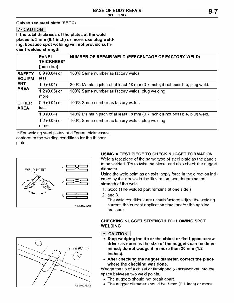
Galvanized steel plate (SECC)CAUTION
If the total thickness of the plates at the weld places is 3 mm (0.1 inch) or more, use plug weld-ing, because spot welding will not provide suffi-cient welded strength.
*: For welding steel plates of different thicknesses, conform to the welding conditions for the thinner plate.
.
USING A TEST PIECE TO CHECK NUGGET FORMATIONWeld a test piece of the same type of steel plate as the panels to be welded. Try to twist the piece, and also check the nugget diameter.Using the weld point as an axis, apply force in the direction indi-cated by the arrows in the illustration, and determine the strength of the weld.1. Good (The welded part remains at one side.)2. and 3.
The weld conditions are unsatisfactory; adjust the welding current, the current application time, and/or the applied pressure.
.
CHECKING NUGGET STRENGTH FOLLOWING SPOT WELDING
CAUTION• Stop wedging the tip or the chisel or flat-tipped screw-
driver as soon as the size of the nuggets can be deter-mined; do not wedge it in more than 30 mm (1.2 inches).
• After checking the nugget diameter, correct the place where the checking was done.
Wedge the tip of a chisel or flat-tipped (-) screwdriver into the space between two weld points.
• The nuggets should not break apart.• The nugget diameter should be 3 mm (0.1 inch) or more.
PANEL THICKNESS* [mm (in.)]
NUMBER OF REPAIR WELD (PERCENTAGE OF FACTORY WELD)
SAFETY EQUIPMENT AREA
0.9 (0.04) or less
100% Same number as factory welds
1.0 (0.04) 200% Maintain pitch of at least 18 mm (0.7 inch); if not possible, plug weld.1.2 (0.05) or more
100% Same number as factory welds; plug welding
OTHER AREA
0.9 (0.04) or less
100% Same number as factory welds
1.0 (0.04) 140% Maintain pitch of at least 18 mm (0.7 inch); if not possible, plug weld.1.2 (0.05) or more
100% Same number as factory welds; plug welding
AB200032AB
WELD POINT 1
2
3
AB200033AB
3 mm (0.1 in)

WELDINGBASE OF BODY REPAIR9-8
GAS SHIELD ARC WELDINGM4090003000010
Gas shielded arc welding is one method of arc weld-ing. In this method, while the area to be welded is shielded from the air by a layer of inert gas (such as argon) or carbon dioxide gas, the filler metal (wire) is fed from the torch nozzle at a constant rate and an electric arc is generated between the tip of the wire and the area being welded, thus generating heat to
fuse the area. There are two types of gas shielded arc welding, classified according to the gas they use as the shield gas: carbon dioxide (CO2) gas shielded arc welding, and MIG welding, which uses an inert gas (such as argon).However, herein we will refer to all gas shielded arc welding as MIG welding.
MIG SPOT WELDING
This welding method is used in areas where regular spot welding cannot be done. The two panels are stacked together, the tip of the torch (one designed for use in MIG spot welding) is positioned on one side, an arc is generated for a short time, and a par-tial melting is done to obtain a spot weld..
ProcedureCAUTION
• Make sure that the area to be welded is per-fectly clean; remove oxidation film, scales, rust, dirt, etc.
• The two panels to be welded must be in per-fect contact with each other.
• The number and pitch of the weld points should be approximately the same as for the factory welds.
1. Position the tip of the nozzle at a right angle to the surface to be welded.
2. Being sure that the two prongs are not leaning to either side, set them in direct contact with the panel to the welded.
3. Welding will begin when the torch trigger is squeezed, and will stop automatically when the weld is complete.
.
AB200035
NOZZLE
WIRE
CONTACT TIP
METAL VAPORSHIELD GAS
AB
AB200036AB200036AB
WIRE
GAS CUP
GAS OUTLET

WELDINGBASE OF BODY REPAIR 9-9
FEATURES OF MIG SPOT WELDINGIn comparison to resistance spot welding, MIG spot welding has the following advantages and disadvan-tages.
.
ITEM MIG SPOT WELDING ELECTRIC RESISTANCE SPOT WELDINGWorking characteristics
• Light weight• Welding possible at various
positions (no limit upon welding positions)
• Although the torch with separate transformer is lightweight, the torch combined with transformer type is heavy.
• The arm must be exchanged to conform to the weld location.
Weld time/point Slow (0.5 second or more) Fast (0.5 second or less)Treatment after welding
Necessary (grinding by grinder, etc.)
Unnecessary
Power High voltage, low current(15 - 30 V, 50 - 200 A)
Low voltage, high current(2 - 4 V, 4 - 10 kA)
Flux material • CO2 (carbonic acid gas)• Weld wire
Unnecessary
Weld points/10 minutes(rate of use)
• 25 points or less• Arc instability and contact tip
burn if rate of use is exceeded.
• 50 - 60 points• Welding rod deformation and transformer
overheating if rate of use is exceeded.Distortion caused by welding
Occurs easily Rare
Welding strength Depends on strength of welding wire itself.
• Same as base material• Little oxidation• Uniform welding quality
Weld traces Button head (slightly convex) Slight concave(Almost no indentation if swivel tip used.)
Re-repairability(cutting away welded area)
Difficult(Much welding trace High hardness of weld points)
Easy(Can be separated by spot cutter.)
AB200037AB
SWIVEL TIP

WELDINGBASE OF BODY REPAIR9-10
The MIG welding done around the doors, wheelhouse arches, etc., to prevent the flanges from coming undone after hemming work is also called MIG spot welding.PLUG WELDINGCAUTION
In order to prevent the formation of blowholes, fill in each hole completely in one pass.Be sure that the two panels are in perfect contact.Be sure that the penetration goes all the way to the bottom panel.Plug welding is done by making holes 5 to 6 mm (0.2 inch) in diameter in one of the panels to be welded together, positioning the torch at a right angle to the holes and then filling in the holes one at a time.
CONTINUOUS WELDINGThere are several types of continuous welding: fillet (lap joint) welding, butt welding, T joint welding, gap welding, etc.; these are called short-circuit arc welding, and provide a stable arc at a relatively low current.
.
Torch angle and welding techniqueThere are two welding techniques: forehand welding and back-hand welding.Forehand welding: Penetration is shallow and the bead is flat.Backhand welding: Penetration is deep and the bead has a
convex shape.
AB200038AB
AB200040AB
TORCH
PERFECT CONTACT
5 TO 6 mm(0.2 in)DIAMETERHOLE
AB200041

WELDINGBASE OF BODY REPAIR 9-11
The angle of the torch should be 15 degree angle to 30 degree angle for either technique, and the tip should be maintained at a distance of 6 to 10 mm (0.2 to 0.4 inch) from the surface being welded.
.
Preventing warping1. Backhand technique
Because the direction for each weld pass and that for the fusion progression are opposite, the residual stress is evenly distributed.
2. Symmetrical techniqueBecause the welds are made in symmetrical positions in relation to the centre of the joint, the residual stress is also symmetrical.
3. "Stepping stone" techniqueBecause the welds are made at random positions, the residual stress is the most evenly distributed; however, the possibility of flaws at the starting and stopping points is rela-tively high.
NOTES REGARDING MIG WELDINGNote the following notes regarding MIG welding.1. The surface to be welded must be perfectly
clean; be sure to remove any non-conductive paint.
2. If the end of the wire forms into a ball, it will adversely affect the formation of the arc; cut the end off with a pair of wire snips or a similar tool.
3. Select a welding current to match the thickness of the panels being welded.
4. For continuous welding, maintain a constant weld speed and keep both the height and the width of the bead constant.In addition, the tack welding pitch and the welding bead should be shorter as the thickness of the panels being welded decreases.
OTHER TYPES OF WELDINGM4090004000013
BRAZINGIn brazing, a filler metal is melted into the joint of the panels to be welded at a comparatively low tempera-ture to fuse them together without melting the panels themselves. In other words, through the aid of a flux and because of the capillarity phenomenon, the mol-ten filler metal will flow into the joint between the two panels which are in contact with each other and spread along the metal surfaces. When this molten filler metal cools and solidifies, it will from a strong joint of the two panels. Note that, if two panels of dif-ferent kinds of metal are brazed, the electrolysis gen-erated between the two metals will cause moisture to from, which will result in corrosion.
Panels should not be connected together by brazing at any place except those places indicated. The fol-lowing materials (filler metals) are usually used for brazing.1. Brass filler metal (brass solder)
Brass filler metal is an alloy consisting of 60% copper and 40% zinc with a melting temperature of approximately 850 to 1,050°C (1,562 to 1,922°F), and it is the most commonly used braz-ing filler metal used for body repair.The filler metal itself is coated with flux to facili-tate penetration between the panels to be joined.
AB200042
15˚ - 30˚ 15˚ - 30˚
FOREHANDTECHNIQUE
BACKHANDTECHNIQUE
AB
AB200043AB
ANTI-WARP WELDING TECHNIQUES
1.
2.
3.
BACKHAND TECHNIQUE
SYMMETRICAL TECHNIQUE
"STEPPING STONE" TECHNIQUE
5 4 3 2 1
54 321
4 32 1

WELDINGBASE OF BODY REPAIR9-12
2. Silver alloy filler metal (silver solder)Silver alloy filler metal consists of silver, copper, zinc or cadmium, nickel, and tin, or other metals.
This filler metal is most applicable for the brazing of steel and non-ferrous alloy other than alumin-ium, magnesium, and others with low melting points.
Notes with regard to brazing work
• Use a wire brush, sandpaper, file etc., to remove any oxide film grease, dirt, etc., from the surfaces of the panels to be brazed.
• When doing brass brazing, if the panels and the filler metal are heated excessively, a weak iron-copper alloy will form, which could crack easily. Be careful not to apply excessive heat.
• The joint of the panels must overlap as indicated in the illustration.
GAS WELDINGGas welding is a method in which a high temperature flame is used to melt both a welding rod and the base metal (panels) to make a fused joint. Oxy-acetylene is the most common type of gas welding. However, because of the extremely high tempera-ture of the fused joint, the strength of the steel plate deterio-rates, and there is a higher possibility of warping. This method, therefore, is not very suitable for body repair.
.
The flame in gas welding can be classified according to the ratio of acetylene and oxygen.
AB200044AB200044ABEXAMPLES OF BRAZED JOINTS
AB200049
DEPOSITE
BASE METAL
WELDING ROD
OXY-ACETYLENEFLAME
AB
AB200050AB200050 AB
FLAME CORE OUTER FLAME
ACETYLENE CONE
FLAME CORE OUTER FLAME FLAME CORE OUTER FLAME
1. CARBURIZING FLAME 2. STANDARD FLAME 3. PEROXIDE FLAME

WELDINGBASE OF BODY REPAIR 9-13
1. Carburizing flame (acetylene-rich flame)This flame has an excess of acetylene or a defi-ciency of oxygen. The incomplete combustion gives off a black smoke, and two flame cores can be seen inside the deformed yellow flame. The flame itself is large, but the temperature is rela-tively low, making this flame unsuitable for weld-ing.
2. Standard flame (neutral-mixture flame)This flame has approximately equal amounts of acetylene and oxygen. The length is shorter than that of the carburizing flame; the flame core is rounded; and it is clear and bright.The carbon in the acetylene is burned completely, resulting in the maximum obtainable temperature.This is the flame most commonly used for weld-ing.
3. Peroxide flame (oxygen-rich flame)This flame has an excess of oxygen or a defi-ciency of acetylene. The flame core is shorter and sharper, and the entire flame has a blackish-purplish color. The combustion is unstable, and the flame flickers continuously.
.
Notes with regard to gas welding1. Handle the oxygen and acetylene tanks carefully.2. Adjust the flame in accordance with the type of
metal being welded.3. Select a nozzle to match the work to be done.
Avoid overheating and adhesion of foreign matter (dirt, etc.).
4. The following points are particularly important when welding mild steel plate.
• Melt a sufficient amount of welding rod, but be careful not to melt the base metal. Use the same amount of welding rod on both sides.
• Use the correct amount of welding rod in accordance with the melting point of the base metal.
• Avoid welding over places which have been welded before.
• In order to avoid warping, do only the amount of tack welding that is absolutely required.

BODY REPAIRBASE OF BODY REPAIR9-14
BODY REPAIRSTANDARD BODY REPAIR PROCEDURES
M4090006000031The following is an explanation of the standard repair procedures for the monocoque body and the frame-type body. Furthermore, please refer to the replace-ment of welded panels for the applicable model for information concerning the procedures for replace-ment of panels (as classified by position) for the vari-ous models.NOTE: That reference should be made to page 9-26 concerning repair procedures for the frame of frame-type vehicles.
STANDARD PROCEDURES FOR REPLACEMENT OF WELDED PANELSIn order to maintain the proper levels of strength, rigidity, and precision when making welded panel replacements, it is essential to first gain a thorough understanding of the body structure, and then to per-form all repair operations carefully and correctly. In addition, when performing the operations, be sure to use the proper protective equipment for each opera-tion.
.
CAUTION• Select an appropriate location for the cutting operation,
and perform the work carefully, so as not to cut into the reinforcements located inside the pillars, panels which are not be replaced, or any other such parts.
• There are harnesses, hoses, and other such parts routed inside the front pillar, the rear pillar, the fender shield, the side sill, etc.; perform the repair work only after any such material has been removed.
• For overlap cutting, allow an overlap of approximately 30 to 50 mm (1.2 to 2.0 inches) when performing the cutting operation.
1. Rough cutting of panelsFirst make a rough cutting of a portion of the panel to be replaced, and then remove that portion, thus making it easier to break the spot welds.
2. Removal of the paint coat from spot-welded pointsIn order to clearly identify the spot-welded points, remove the paint coat from areas where it is difficult to determine the spot welds.
3. Cutting and separation of spot-welded pointsIn order to perform cutting and separation of spot-welded points, use a spot weld cutter which is larger than the size of the nugget to make a hole only in the panels to be replaced.When cutting and separating spot-welded points in places where the surrounding panel or other parts interfere with the spot weld cutter, or if the operation is hampered by a lack of space, bend back the flanges in order to make the work easier.If a spot-weld cutter cannot be used at all, cut and separate the spot welds by using a chisel or similar tool.
AB200051
AB200052
AB200053

BODY REPAIRBASE OF BODY REPAIR 9-15
NOTE: If a replacement panel is to be mounted by doing plug welding from the side of the panel remaining on the body, either a hole can be made in the panel on the body, or a hole can be made right through both the panel which is to remain on the body and the panel to be replaced.
4. Breaking of brazing and arc weldsHeat only the brazed or arc welded portion (such as the upper portion of pillars, etc.), and then separate by using a screwdriver while melting occurs.CAUTION
When performing this operation, warping of the surround-ing panels may occur if an excessive amount of heat is applied; therefore, be careful to avoid doing this.
5. Finishing work of spot weldingGrind and smooth any weld traces which might be left on the body surface by using an air grinder or similar tool, being careful not to damage any of the panels which is not to be replaced. When performing this operation, be sure to wear safety goggles (dustproof glasses).
6. Making of holes in new parts for MIG plug weldingMake holes approximately 5 to 6 mm (0.2 inch) in diameter at points where plug welding is to be performed because spot welding is not possible.
AB200054
AB200055
AB200056
AB200057

BODY REPAIRBASE OF BODY REPAIR9-16
7. Flange correction for spot weld tracesCorrect any flanges that become bent or deformed when spot welds are broken or during other work.
CAUTIONDo not use a flame for paint coat removal because doing so might damage the paint coat of panels which are not to be replaced, thus causing corrosion.8. Removal of the paint coat from new parts and from the
vehicle bodyIn order to provide for the proper flow of electric current during spot welding operations, remove the paint coat from both sides of the new part and the body by using a polisher wheel or similar tool.
9. Rough cutting of new partsCut off the unnecessary portions of new parts. Allow an overlap of approximately 30 to 50 mm (1.2 to 2.0 inches) when performing overlap cutting of the pillars, side sills, or other locations.
CAUTIONCarefully select the location for cutting, taking care not to cut a reinforcement at the inner side of a pillar, etc. or a panel that is not to be replaced.10.Overlap cutting of new parts
For locations in which butt welding is to be done, first temporarily attach the new parts to the body, and then cut the two panels simultaneously.NOTE: If a reinforcement or a panel which is not to be replaced is cut accidentally, first repair the mistake by weld-ing before proceeding with the rest of the work.
AB200058
AB200059
AB200060
AB200061AB
EDGE OF THE NEW PART
EDGE OF THE PANEL ON THE BODY

BODY REPAIRBASE OF BODY REPAIR 9-17
CAUTIONPerform the operations carefully so that the cut ends fit together properly.11.Cutting of new parts by using a measurement marking
If overlap cutting is not possible in a place where butt welding is to be done, make a measurement marking on the new part at the exact same measurement which was used for the cutting of the body panel, and then cut the new part by using this measurement marking.
• Two-layer constructionWhen cutting a front pillar or center pillar which has a two-layer construction but no reinforcement, make the cutting of the inner panel and that of the outer panel approximately 50 mm (2.0 inches) apart in order to obtain maximum strength.
• Three-layer constructionWhen cutting a front pillar or center pillar which has a three-layer (including a reinforcement) construction (double-box construction), cut the outer panel and the reinforcement at the same position, and don't forget to butt weld the rein-forcement. If the inner panel is an assembly replacement part, cut it at two places in order to provide ample working space for the butt welding of the reinforcement.
12.Application of spot sealer to spot-welded pointsApply an electro-conductive spot sealer to the connecting surfaces of both the new parts and the vehicle body in order to provide corrosion protection.
AB200062AB
OUTER PANEL
APPROX. 50 mm(2.0 in)INNER PANEL
TWO-LAYERCONSTRUCTION
AB200063AB
INNER PANELINNER PANELCUT LINE
INNER PANEL CUT LINE
OUTER PANELAND REINFORCE-MENT CUT LINE
THREE-LAYER CONSTRUCTION
AB200064

BODY REPAIRBASE OF BODY REPAIR9-18
CAUTIONDuring temporary mounting, it is extremely important to obtain accurate measurements for each component. The mounting positions for the front and rear suspensions are especially crucial with regard to safety; therefore, it is nec-essary that all work concerning these areas be done care-fully and correctly.13.Temporary mounting of new parts1. In order to bring the new parts into the proper mounting
position, measure each part carefully and make any correc-tions necessary in order to obtain agreement with the mea-surements.
2. In addition, make temporary welds, and then check to con-firm that the closing and fit of the doors, fenders, etc., are correct.For parts which should be symmetrical to the body center, measure the distances from the body center point to both the left part and the right part, and confirm that the dis-tances are the same.
CAUTIONWeld completely so that there are no pinholes.14.Butt welding
For burr welding, make a 10 to 15 mm (0.4 to 0.6 inch) MIG spot weld, and then, in order to prevent warping which might be caused by the welding heat, complete the welding by making welds of the specified width at alternate positions.
AB200065
AB200066
AB200067
AB200068

BODY REPAIRBASE OF BODY REPAIR 9-19
15.Spot weldingWhen doing spot welding, it is not only important to correctly position the electrode tips, but also to hold the two panels securely together with vise-grip pliers or some other type of clamps, being sure that they are in perfect contact with each other.
• Be sure that the force applied by the arm is sufficient.• Use a test piece to check the secondary current and the
current application time of the spot welder, and adjust the values as appropriate.
16.Plug weldingIf spot welds cannot be made, make holes for plug welding in the new parts, and then MIG weld. Because the quality of the fusion varies according to the size of the holes, they should be about 5 to 6 mm (0.2 inch) in diameter. In addition, be sure the two surfaces are in complete contact with each other by using vise-grip pliers to securely hold them.NOTE: Depending on the working conditions, it might also be necessary to make holes in the panel remaining on the body
17.Hemming work(1) If hemming work is to be done for the rear wheel cut line,
the door outer panels, or other parts, use a hammer and a dolly or a hemming tool to do the work manually.
AB200070
AB200070
AB200071
AB200072 AB
HEMMING TOOL

BODY REPAIRBASE OF BODY REPAIR9-20
(2) After completing the hemming work, make MIG spot welds at 50 to 60 mm (2.0 to 2.4 inches) intervals on the inside.
CAUTIONBe sure not to grind the panel down too much. Before welding the outer panel, be sure to apply an anticorrosion agent.18.Finishing work for butt welding and plug welding
Do the finishing work to smooth the protruding weld traces. However, the butt joints of reinforcements and other internal parts will be stronger if the weld traces are not finished.
19.Application of body sealantApply a coating of sealant carefully, without breaks, as described in the section (of the manual corresponding to that model).NOTE: After application has been made to any external sur-faces, perform smooth-finishing work.
AB200073
AB200074
AB200076

BODY REPAIRBASE OF BODY REPAIR 9-21
CAUTIONWipe off any anticorrosion agent which oozes out onto surfaces to be painted later; the presence of such anticor-rosion agent would prevent correct adhesion of the paint coat.20.Application of an anticorrosion agent
Apply an ample amount of anticorrosion agent to any welded areas and to all surfaces from which the paint coat was removed.The paint coat of welded areas will have been damaged by the heat; be sure to apply an anticorrosion agent to surfaces to be repaired.Use an aerosol-type anticorrosion agent for application to the side sills, the pillars, and other similar parts which have a hollow construction, by utilizing the trim mounting holes, etc.
21.Application of undercoatingIf the underbody is repaired or replaced, carefully apply a coating of undercoating as described in the section (of the manual corresponding to that model).
CAUTIONS REGARDING BODY REPAIRBecause each component part of a single-unit con-struction body makes some contribution, more or less, to the overall strength of that body, it is neces-sary to sufficiently understand the actual function of any part to be repaired before attempting any repair or welding procedure..
STRENGTH AND RIGIDITY1. The suspension installation part plays an impor-
tant role, determining the wheel alignment. Wheel misalignment is of course potentially vary danger-ous because it can lead to driving instability, one-sided braking, abnormal tire wear, abnormal vibration, etc.
At the time of repair, it is particularly necessary to take measurements at the components noted below, and to make all welds and installations with special care.
• Front sidemember• Rear floor sidemember• Front wheelhouse (inner)• Rear wheelhouse (inner) (Independent rear
suspension type)2. Because the places where the floor panel and
sidemember parts are joined have an important effect upon the rigidity of the entire body, welds in these places must be done with particular care.
3. After repairs have been completed, the wheel alignment, wheel base, tread, etc., must be care-fully checked to be sure that there is no deviation.
.
AB200077
AB200078
AB200079

BODY REPAIRBASE OF BODY REPAIR9-22
SAFETY1. Procedures related to the installation of any com-
ponent related to safety must be done with partic-ular care in order to assure full maintenance of safety.
• Suspension installation parts• Fuel pipe• Brakes• Fuel tank installation parts, etc.
2. Because seat belts are directly related to driver and passenger safety, any welds of seat belt anchor points or reinforcements must be done with particular care in order to maintain strength.
.
PREVENTION OF CORROSION AND OF WATER OR DUST ENTRY1. After any work is completed, it is important to
completely remove any welding residue, particles or residue from cutting, and any other dirt, etc.
2. Corrosion-prevention material must without fail be applied at the following places:
• At any place where paint has flaked off or peeled away.
• At any surfaces that have been cut.• At the outer and inner side of every welded
place.• Within any semi-enclosed structure or compo-
nent (aerosol-type rust inhibitors are effective for difficult-to-reach places.)
• At the outer and inner side of any place sub-jected to heat.
3. Apply a coating of undercoating if the underbody is repaired.
4. Use spot sealer if spot welds are made.5. Repair any scratches to panels made by mold-
ings, sashes, etc.6. Carefully apply body sealant to panel connection
joints and other fitting places.7. Tape over any unused holes in the panel inner
side by using sealing tape..
VIBRATION AND NOISE1. Prevent any decrease of tensional rigidity caused
by welding distortion.2. Carefully apply body sealant to panel connection
joints and other fitting places.3. Tape over any unused holes in the panel inner
side by using sealing tape..
CONTACT AND ALIGNMENT1. In order to maintain the precision of openings,
make careful measurements as repairs are being made.
2. Make contact/alignment adjustments of door hinge, lid, and hood hinge installation parts.
THEFT PROTECTIONM4090007000023
In order to prevent theft, following Vehicle Identification Number (VIN) has been engraved and attached, in the form of a label to the engine, transmission, and main of the outer body:
Engine cylinder block, Transmission housing, Fender, Doors, Quarter panel, Hood, Trunk lid, Bumpers
Furthermore, supplementary parts for the main portions of the outer body have theft protection labels attached and the sup-plementary parts for the engine and the transmission are engraved with the same details.
AC101015
FOR ORIGINAL PARTS
FOR REPLACEMENT PARTS
AB
THEFT PROTECTION LABEL

BODY REPAIRBASE OF BODY REPAIR 9-23
PANEL REPAIR CAUTION1. Take care when respraying the original part to cover the theft
protection label with masking tape prior to respraying. In addition, remember to peel off the masking tape after completion of the respray.
2. Because theft protection labels on the supplementary parts are covered with masking tape already, they can be resprayed just as they are.
3. Take care not to peel off the theft protection labels from either the original or the supplementary parts.
HOW TO PEEL OFF THE SURFACE MASKING FILM FROM THE THEFT-PROTECTION LABEL
CAUTIONBe careful not to damage the paint surface or the label itself.1. Using a sharp knife at the corner of the label surface, lift up
the masking film only.2. Grasp the masking film and peel it all off.NOTE: If the masking film tears, repeat from step 1. Use the knife, however, to lift the opposite corner of the label, rather than trying to continue peeling from the place where it tore.
AB200080AB
KNIFE
MASKING FILM
BODY REPAIRBASE OF BODY REPAIR9-24
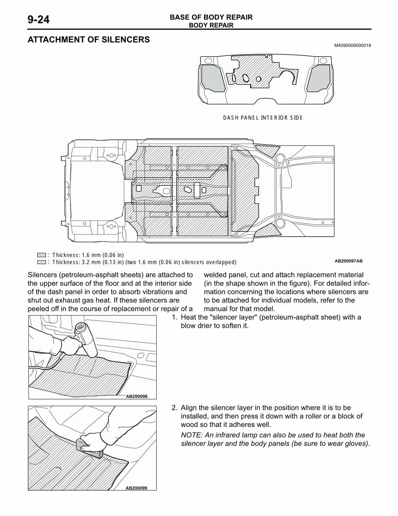
ATTACHMENT OF SILENCERSM4090009000018
Silencers (petroleum-asphalt sheets) are attached to the upper surface of the floor and at the interior side of the dash panel in order to absorb vibrations and shut out exhaust gas heat. If these silencers are peeled off in the course of replacement or repair of a
welded panel, cut and attach replacement material (in the shape shown in the figure). For detailed infor-mation concerning the locations where silencers are to be attached for individual models, refer to the manual for that model.
1. Heat the "silencer layer" (petroleum-asphalt sheet) with a blow drier to soften it.
2. Align the silencer layer in the position where it is to be installed, and then press it down with a roller or a block of wood so that it adheres well.NOTE: An infrared lamp can also be used to heat both the silencer layer and the body panels (be sure to wear gloves).
AB200097:: AB
DASH PANEL INTERIOR SIDE
Thickness: 1.6 mm (0.06 in)Thickness: 3.2 mm (0.13 in) (two 1.6 mm (0.06 in) silencers overlapped)
AB200098
AB200099

BODY REPAIRBASE OF BODY REPAIR 9-25
POSITIONING DIMENSIONS FOR OPENINGSM4090010000012
When replacing the panel of the opening of the front pillar, center pillar and other openings, make a point to securely bite the poltapower, etc. so the position of the opening is not off-center. Upon assembling, adjust the opening dimensions to the standard speci-fications and then weld.
STANDARD PROCEDURES FOR SHEET METAL WORKM4090012000018
REPAIRS USING A HAMMER AND DOLLYIt a damaged external panel, etc., can be reused, the usual way to repair it is by using a hammer and dolly to hammer out the damaged area. The following describes these repair procedures.
.
1. Check whether or not there is foreign material (mud, etc.) on the panel surface. If so, clean it away.CAUTION
The surface of the hammer and dolly must be free of scars, etc.2. Select the appropriate hammer and dolly to be used
according to the panel shape.
AB200100
PORTA POWER
AB
BODY REPAIRBASE OF BODY REPAIR9-26
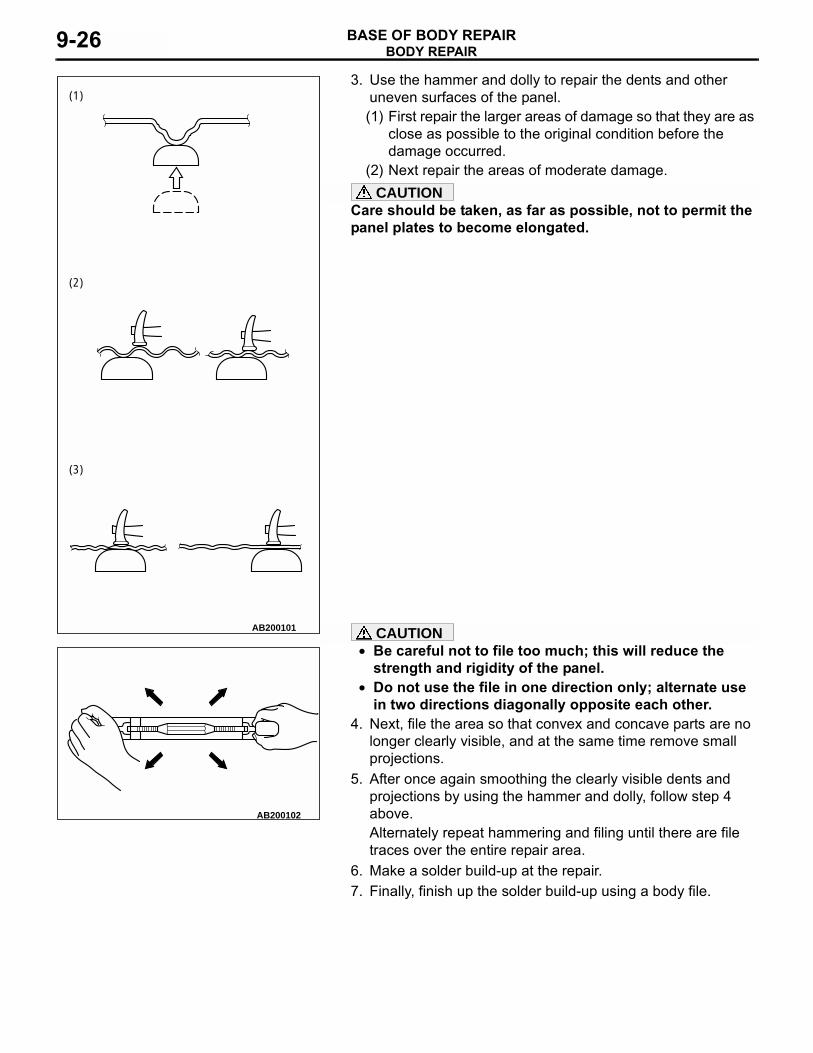
3. Use the hammer and dolly to repair the dents and otheruneven surfaces of the panel.(1) First repair the larger areas of damage so that they are as
close as possible to the original condition before the damage occurred.
(2) Next repair the areas of moderate damage.CAUTION
Care should be taken, as far as possible, not to permit the panel plates to become elongated.
CAUTION• Be careful not to file too much; this will reduce the
strength and rigidity of the panel.• Do not use the file in one direction only; alternate use
in two directions diagonally opposite each other.4. Next, file the area so that convex and concave parts are no
longer clearly visible, and at the same time remove small projections.
5. After once again smoothing the clearly visible dents and projections by using the hammer and dolly, follow step 4 above.Alternately repeat hammering and filing until there are file traces over the entire repair area.
6. Make a solder build-up at the repair.7. Finally, finish up the solder build-up using a body file.
AB200101
(1)
(2)
(3)
AB200102

BODY REPAIRBASE OF BODY REPAIR 9-27
USING A FRAME STRAIGHTENERM4090013000011
For serious and extensive damage, when for exam-ple the damage extends to the frame of members, it is necessary to first use a frame straightener to make a rough, overall repair of the body, and then to pro-ceed to careful repairs of each individual area of damage. When a frame straightener is used for body repairs, it is a fundamental principle that the pulling should be in the direction from which the impact was sustained, and from the opposite direction. If this is, in error, not done, previously undamaged compo-nents will be deformed, and repair may become impossible.It is for that reason that it is important to decide upon the method of repair, especially regarding the initial overall repair, by following the steps below.OVERALL ROUGH REPAIRS1. First, analyze the impact. This means analysis
and consideration of the point of collision, the speed at the time of collision, and the strength, weight and shape of the object hit.
2. Then get a complete understanding of the condition of the existing damage. In particular, if the damage extends to the suspension installation components, an inspection must be made to determine whether or not there is any deviation of the frame or body alignment.
3. Finally, determine what repair methods should be used.
• To what extent will frame straightening and other overall repairs be necessary in order to restore the damaged areas to the way they were?
• At what stage of the repairs should panels adjoin-ing the components to be frame straightened, etc., be removed?
• Decide upon the work steps and restoration methods to be followed after the rough, overall repairs are completed.
Select the frame straightener based upon the results of above, and use it to pull in the appropriate direc-tion. More than one direction may be appropriate, depending upon the damage.If the damage is of a moderate degree or less, it may be possible to do all that is necessary in one pull.If, however, the damage is major, that is to say if repairs must be made to components of the passen-ger compartment such as the dash panel, etc., it may be necessary, after completing the first pull, to set up the frame straightener at a different position and use it again at that position.
FRAME STRAIGHTENING NOTES• For safety, no one must be standing in the direction of the
pull.• Wires or chains should be used for protection in the event
of an accident.• For frame straightening of body with frame, care should be
taken regarding the position (body mount) of installation to the frame. The reason for this is that usually mounting rub-ber pieces are used at the installation part in order to improve vibration prevention, and these mounting rubber pieces might be deformed if there is a deviation of the installation position.
• If the part to be pulled is made of high-tensile steel (which has a higher tensional strength and yield point than ordinary steel), the pulling must be done with care in order to avoid "overpull" and "springback." It is particularly important for the pulling of sidemembers and other reinforcement compo-nents made of high-tensile steel that the pulling not be all done at one time; pull gradually while using a hammer to repair distorted areas as the pulling is done.
AB200103AB
WIRES FOR PROTECTION

BODY REPAIRBASE OF BODY REPAIR9-28
FRAME REPAIR PROCEDURESM4090014000014
The frame is subjected to the following types of loads.
• Vertical loads... Vertical loads may occur either while stopped or during travel.
• Lateral (horizontal) loads... This type of loads occurs during turning, start-off and braking.
• Torsional loads... Torsional loads occur while traveling on roads with poor surface conditions.
These various types of loads are compounded under various conditions, and are applied to the frame.As a result, it is important, before attempting to repair the frame, to carefully observe the shape of the dam-aged part and to in that way fully understand the cause of the damage.
CHECKING FOR FRAME CRACKING OR FLANKINGCheck, by using a test hammer, for flaking or cracking of the welded surface of the sidemembers, crossmembers and brack-ets.
REPAIRING CRACKSIf the check reveals a crack(s) in the frame, repair as described bellow.1. Remove the components near the crack.2. Make φ 6 - 8 mm (0.2 - 0.3 inch) holes (to prevent further
cracking), by using a drill, at points 7 - 8 mm (0.3 inch) from the crack ends.
3. Use a φ 10 - 12 mm (0.4 - 0.5 inch) drill to bevel the hole openings.
AB200127AB
TEST HAMMER
SIDEMEMBER
AB200128
CRACK-STOP HOLE
CRACK
A
A
Ø6 - 8 mm(0.2 - 0.3 in)
A : 7 - 8 mm (0.3in) AB
AB200129AB
Ø10 - 12 mm(0.4 - 0.5 in)
Ø10 - 12 mm (0.4 - 0.5 in)
Ø6 - 8 mm (0.2 - 0.3 in)
BODY REPAIRBASE OF BODY REPAIR 9-29
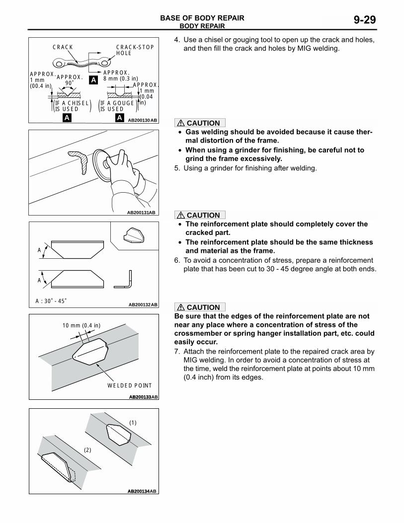
4. Use a chisel or gouging tool to open up the crack and holes, and then fill the crack and holes by MIG welding.
CAUTION• Gas welding should be avoided because it cause ther-
mal distortion of the frame.• When using a grinder for finishing, be careful not to
grind the frame excessively.5. Using a grinder for finishing after welding.
CAUTION• The reinforcement plate should completely cover the
cracked part.• The reinforcement plate should be the same thickness
and material as the frame.6. To avoid a concentration of stress, prepare a reinforcement
plate that has been cut to 30 - 45 degree angle at both ends.
CAUTIONBe sure that the edges of the reinforcement plate are not near any place where a concentration of stress of the crossmember or spring hanger installation part, etc. could easily occur.7. Attach the reinforcement plate to the repaired crack area by
MIG welding. In order to avoid a concentration of stress at the time, weld the reinforcement plate at points about 10 mm (0.4 inch) from its edges.
AB200130AB
CRACK CRACK-STOPHOLE
APPROX.8 mm (0.3 in)
APPROX. 1 mm (0.04 in)
APPROX.1 mm (00.4 in)
APPROX.90˚
IF A CHISEL IS USED
IF A GOUGE IS USED
A
AA
AB200131AB
AB200132
A
A
A : 30˚ - 45˚AB
AB200133AB200133
10 mm (0.4 in)
WELDED POINT
AB
AB200134AB200134AB
(2)
(1)

BODY REPAIRBASE OF BODY REPAIR9-30
NOTE: If the crack is at the upper side of the frame, attach the reinforcement plate facing downward, as shown in (1).If the crack is at the lower side, attach the reinforcement plate to face upward, as shown in (2).
8. Finally, apply a coating of chassis black to the repaired area and to any places where the coating has flaked off.
NOTES REGARDING REPAIR WORKM4090015000017
SAFETY MEASURES.
PROTECTIVE GEARDuring body repair work, a work suit, a work cap, and safety shoes should be worn at all times. Depending on the work being done, safety glasses, gloves, ear protectors, a dustproof mask, etc., should also be worn as needed.1. Safety glasses2. Work cap3. Ear protectors4. Head protector5. Work suit6. Dustproof mask7. Work apron8. Welding gloves9. Foot and ankle protectors
10. Safety shoes11. Work gloves
.
SUPPLEMENTAL RESTRAINT SYSTEM (SRS)1. Items to review when servicing SRS
(1) Be sure to read Service Manual GROUP 52B, Supplemental Restraint System (SRS). For safe operation, please follow the directions and heed all warnings.
(2) Wait at least 60 seconds after disconnecting the battery cable before doing any further work. The SRS system is designed to retain enough voltage to deploy the air bag even after the battery has been disconnected. Serious injury may result from unintended air bag deployment if work is done on the SRS system immediately after the battery cable is disconnected.
(3) Warning labels must be heeded when servicing or handling SRS components.
(4) Always use the designated special tools and test equipment.
(5) Store components removed from the SRS in a clean and dry place. The air bag module should be stored on a flat surface and placed so that the pad surface is facing upward.
(6) Never attempt to disassemble or repair the SRS components (SRS-ECU, air bag module and clock spring). If there is a defect, replace the defective part.
(7) Whenever you finish servicing the SRS, check the SRS warning light operation to make sure that the system functions properly.
(8) Be sure to deploy the air bag before disposing of the air bag module or disposing of a vehicle equipped with an air bag.
2. Observe the following when carrying out operations on places where SRS components are installed, including operations not directly related to the SRS air bag.(1) When removing or installing parts, do not allow
any impact or shock to occur to the SRS components.
AB200104
1
4
5 6
7 8
9 10 11
2 3

BODY REPAIRBASE OF BODY REPAIR 9-31
(2) If heat damage may occur during paint work, remove the SRS-ECU, the air bag module, clock spring, the front impact sensor, the side impact sensor, and the seat belt pre-tensioner.
• SRS-ECU, air bag module, clock spring, front impact sensor, the side impact sensor: 93 °C (200 °F) or more
• Seat belt pre-tensioner: 90 °C (194 °F) or more
.
SECURING THE VEHICLEIf the vehicle is raised on a jack, be sure to always support it with jack stands positioned at the specified points..
CLEARING THE AREA OF FLAMMABLE MATERIALSBecause of the presence of many various kinds of flammable materials, organic solvents, etc., in the work area, there is always the possibility of a fire or explosion. It is, therefore, important to keep the work area as clear as possible of such dangerous materials..
HANDLING ELECTRONIC PARTS AND SEMICONDUCTORSWARNING
Battery posts, terminals and related accessories con-tain lead and lead compounds. WASH HANDS AFTER HANDLING.When the body is used as the ground during welding for body repairs, be absolutely sure to first disconnect the battery's posi-tive (+) cable.
CAUTION• Be sure that both the ignition and lighting switches are
"LOCK" (OFF) position before either disconnecting or reconnecting a battery cable. (If this is not done, equip-ment containing semiconductors could be damaged.)
• Note that the memory of electronic equipment having a memory function will be cleared when the battery cable is disconnected.
NOTE: Vehicles today include a great many electronic parts and components, and these are in general very susceptible to adverse effects caused by overcurrent, reverse current, elec-tromagnetic waves, high temperature, high humidity, impacts, etc. In particular, such electronic components can be damaged if there is a large current flow during welding from the body side, etc.This is because, for electronic components that incorporate a back-up circuit (for memory retention) that functions (by a trickle current) even when the ignition switch is at OFF, an elec-tronic circuit is formed even when the switch is at OFF..
HANDLING COMBUSTIBLE MATERIALSIf welding work is to be done in the area of the fuel tank, the fuel tank must be removed to prevent the generation of flammable gases. Also be sure to cap the inlet port and the pipes of the fuel tank after removal to prevent the escape of any fuel or flammable gases.Wipe up any fuel, oil, etc., spilled in the work area as soon as possible.
AB200105

BODY REPAIRBASE OF BODY REPAIR9-32
Only the amounts of paint to be used for the day's work should be in the work area; do not keep excessive amounts of paint, or paint which is not going to be used, in the work area.HEALTH AND SANITATION PROCEDURESThe following points should be noted for employee health and sanitation.
• The work area should be well ventilated in order to prevent the inhalation of dust, organic solvent vapors, etc.
• All unused paint cans must be securely covered.• Care should be taken to avoid exposure to the skin of adhe-
sives, organic solvents, etc.If an unavoidable exposure occurs, the exposed area should be immediately washed with clean water.
VEHICLE PROTECTION• Vehicle covers (fender covers, seat covers, etc.) and tape (if
there is the possibility of damage by tools, equipment, etc.) should be used to protect painted surfaces, interior/exterior parts and components, etc., from staining and damage.
• For welding operations, a heat-resistant protective cover should be used to protect glass, seats, instrument panel, carpeting, etc.
HEAT-WITHSTAND TEMPERATURES OF RESIN-PLASTIC PARTSM4090016000010
Because resin-plastic parts are deformed by heat, they should be removed if the heat to be applied is high enough to cause deformation, as shown by the table below.
AB200106
AB200107
MATERIAL NAME ABBREVIATION HEAT-DEFORMATION TEMPERATURE °C (°F)
WHERE MAINLY USED
Acrylonitrile styrene acrylate
ASA 80 (176) Door mirror, Pillar garnish, License garnish, Radiator grille
Acrylonitrile butadiene styrene
ABS 80 (176) Air spoiler, Console box, Radiator grille, Rear garnish, Headlight bezel
Cellulose acetate CA 50 to 90 (122 to 194)

BODY REPAIRBASE OF BODY REPAIR 9-33
Cellulose acetate butyrate
CAB 60 to 100 (140 to 212) Door trim molding
Polyamide PA 140 to 160 (284 to 320) Harness connector, Wheel cover, Cooling fan, Fuel strainer
Talc filled polyamide
PA-TD 190 to 200 (374 to 392) Hood garnish, Door outside handle
Polybutylene terephthalate
PBT 120 (248) Room lamp lens, Headlight lens
Polyethylene PE 100 (212) Heater duct, Fender liner, Washer tankHigh density polyethylene
PE-HD (HDPE) 70 to 90 (158 to 194) Fuel tank, Splash shield
Phenole formaldehyde
PF 170 to 190 (338 to 374) Ashtray
Polymethyl methacrylate
PMMA 80 to 100 (176 to 212) Light lens
Polyacetal POM 120 (248) Door regulator handle, Ball joint seatPolypropylene PP 80 (176) Glove compartment, Bumper face,
Pillar trim, Steering wheel, Heater unit, Cooling fan
Polyphenylene ether
PPE (PPO) 130 to 140 (266 to 284) Accelerator pedal pad, Wheel cover, Speaker garnish
Talc filled polypropylene
PP-TD (PPF) 100 (212) Front deck garnish, Stone guard, Floor console, Instrument panel
Talc filled polypropylene (10%)
PP-TD10 (PPF) 110 to 120 (230 to 248) Center pillar trim
Talc filled polypropylene (15%)
PP-TD15 (PPF) 110 to 120 (230 to 248) Front pillar trim, Center pillar trim, Rear pillar trim
Talc filled polypropylene (20%)
PP-TD20 (PPF) 120 to 130 (248 to 266) Beltline trim, Front deck garnish, Front pillar trim
Talc filled polypropylene (30%)
PP-TD30 (PPF) 130 to 140 (266 to 284) Quarter trim, Rear side trim
Polyurethane PUR 80 to 100 (176 to 212) Bumper, Steering wheelPolyurethane (formed)
PUR-E 80 to 100 (176 to 212) Seat cushion, Arm rest, Door trim, Instrument panel
Glass fiber reinforced RIM urethane
PUR-GF [RIM] 100 to 120 (212 to 248) Airdam panel
Polyvinyl alcohol PVAL *1Polyvinyl butyral PVBPolyvinyl chloride PVC 80 (176) Steering wheel, Side protector molding,
Shift lever cover, Window molding
MATERIAL NAME ABBREVIATION HEAT-DEFORMATION TEMPERATURE °C (°F)
WHERE MAINLY USED

BODY REPAIRBASE OF BODY REPAIR9-34
NOTE: .• A slash (/) in the abbreviation indicates that two
different materials make two-layer construction.A plus sign (+) indicates that the two different materials mix each other.
• If the new material symbols designated by the ISO differ form the old symbols, both are given, with the old symbol being enclosed in brackets. ISO: International Organization for Standardiza-tion
• *1: Temperature differs depending on the ratio of the materials included.
• *2: Impossible to fix the temperature due to the multi-layer and foam material structure.
• If an infra-red lamp is used for drying, use a heat-resistant cover, etc., to protect parts.
Thermoplastic elastomer (olefine)
TPO (TEO) 80 (176) Mud guard, Side airdam
Urea formaldehyde UF 120 to 145 (248 to 293)Glass fiber reinforced unsaturated polyester
UP-(GT + TD) [SMC], [BMC]
200 (392) Rear air spoiler
Ethylene vinyl acetate
E/VAC (EVA) 60 (140) Mud guard
Talc filled polypropylene
PP + E/P-TD [HMPP]
80 to 100 (176 to 212) Bumper face, Side airdam, Side protector molding
Polyvinyl chloride, Polyurethane
PVC, PUR-E *2 Instrument panel pad
Thermoplastic elastomer (styrene), Talc filled polypropylene
TES, PP-TD 100 to 120 (212 to 248) Side splash
Polycarbonate + Acrylonitrile butadiene
PC + ABS 120 to 125 (248 to 257) Door outside handle
Polycarbonate + Polyethylene terephthalate
PC + PET 120 (248) Door outside handle
Polycarbonate + Polybutylene terephthalate
PC + PBT 130 to 140 (266 to 284) Door outside handle
Polyphenylene ether + Polyamide 6
PPE (PPO) + PA6 150 to 160 (302 to 320) Wheel cover
Polyphenylene ether + Polyamide 66
PPE (PPO) + PA66
160 to 170 (320 to 338) Wheel cover
Polyphenylene ether + Polystyrene
PPE (PPO) + PS 120 to 130 (248 to 266) Wheel cover
MATERIAL NAME ABBREVIATION HEAT-DEFORMATION TEMPERATURE °C (°F)
WHERE MAINLY USED

BODY REPAIRBASE OF BODY REPAIR 9-35
HOW TO DISTINGUISH TYPES OF PLASTICSM4090017000013
There are various methods that can be employed to determine types of plastics, among them (1) using a chemical solvent, etc., to check it chemically, (2) scratching the material to determine its make-up, (3) cutting of a small piece (where the scar can't be seen) and burning it to judge by the way it burns, etc. The following is an outline of the burning method, which is a relatively simple method.
PLASTIC NAME ABBREVIATION FLAME COLOR COMBUSTION CONDITIONS SELF-EXTINGUISHING ODOR
Polyvinyl chloride PVC Yellow flame top Blue flame bottom
Burns to black residue Yes Irritating acid odor
Polyethylene PE Yellow flame top Blue flame bottom
Burns cleanly while melting
No Candle-like odor
Polypropylene PP Yellow flame top Blue flame bottom
• Burns briskly and drips
• Slight white smoke
No Petroleum-like odor
Polyurethane PUR Orange Crackles as burns; drips No Rubber odorTRUR Orange
Polycarbonate PC Yellow Cinders remain To some extent
Sweet odor
Polyamide (nylon)
PA Yellow flame top Blue flame bottom
Melts and drips Yes Strong formic acid odor
Polyester resin UP Yellow Ashes remain No Styrene odorGlass-fiber-reinforced plastic
FRP Yellow Ashes with glass-fiber remnants remain
No Differs according to plastic type
Phenol resin PF Yellow Ashes remain Yes Formalin odorABS resin ABS Orange Burns accompanied by
foaming and black smoke
No Rubber odor

CORROSION PROTECTIONBASE OF BODY REPAIR9-36
CORROSION PROTECTIONANTICORROSION TREATMENT AT THE FACTORY
M4090019000019Anticorrosion treatment at the time of production includes the following measures.THE USE OF GALVANIZED STEEL PLATE
Because galvanized steel plate has excellent corro-sion resistance, it is used in areas which have a high possibility of painting deficiency.
ZINC PHOSPHATE COATINGIn order to improve the adhesive properties of the paint coat on the steel plate, and also to improve the finish of the paint coat, the entire body is coated with a film of zinc phosphate prior to undergoing the electrodeposition undercoating process.1. Final coat2. Intermediate coat3. Anticorrosion primer4. Undercoat5. Zinc phosphate film6. Steel plate
AB200136AB
: locations where galvanized steel plate is used.
AB200109
1
23
45
6

CORROSION PROTECTIONBASE OF BODY REPAIR 9-37
CATIONIC ELECTRODEPOSITION UNDERCOATING
In the cationic electrodeposition method, the car body is the negative pole, thus preventing damage to the zinc plating of the galvanized body panels or to the chemically formed phosphate crystals. This method, therefore, maximizes the corrosion resis-tance and the results obtained are much better than those from conventional anionic electrodeposition.
BODY SEALINGSealant has been applied to all body panel joints and seams in order to provide resistance to water, dust, and corrosion.
UNDERBODY COATINGAn underbody coating has been applied to the underside of the floor pans, the inside of the doors, etc., in order to provide resistance to vibration, corrosion, and wear.
AB200110ABANIONIC ELECTRODEPOSITION CATIONIC ELECTRODEPOSITION
COUNTERAGENT
ANIONICCOATING
CATIONICCOATING
COUNTERAGENTALKALISOLUTION
AB200111
A
AA - A Section
AB
AB200112

CORROSION PROTECTIONBASE OF BODY REPAIR9-38
WAX INJECTIONWax injection is used at the lower part of the frame, side sill and hollow panels, etc., in order to obtain a better anticorrosion effect.ANTICORROSION PRIMER
Anticorrosion primer is used at the side sill outer pan-els in order to prevent corrosion and to suppress vibration.
SEALING TAPESealing tape is attached at unused holes, at the inner side of the panel, for waterproofing and anticorrosion protection.
AB200113
AB200114AB2001141. ROCKER PANEL PRIMER APPLICATION AB
11
A
A
AB200115AB: Locations for attachment of sealing tape

CORROSION PROTECTIONBASE OF BODY REPAIR 9-39
ANTICORROSION TREATMENT AT THE TIME OF BODY REPAIR WORK
M4090020000013The following procedures should be followed for anticorrosion protection when making repairs.
CORROSION PROTECTION FOR HOLLOW PARTS
CAUTION• Wipe away any excess anticorrosion agent on the
coated surface, because it can adversely affect the coating.
• When spraying the anticorrosion agent, use holes in different areas to ensure that all weld surfaces of the hollow structure are well coated.
The insides of hollow parts (such as the side sill, pillars, etc.) which have been welded are more susceptible to corrosion. Spray an aerosol-type anticorrosion agent into these parts by using the trim mounting holes and other openings.
ANTICORROSION TREATMENT OF ROUGH CUTSAn anticorrosion agent should be applied to rough cuts made in the course of welding, because the surface film has been dam-aged by the heat of welding.
SPOT SEALERIn order to prevent corrosion from occurring at the contact sur-faces of panels which are spot welded, apply an electroconduc-tive spot sealer..
SPOT SEALER APPLICATION STEPS1. Remove all paint, etc., from the areas to be spot welded by
using sandpaper or a pneumatic belt sander.
AB200116
AB200117
AB200118

CORROSION PROTECTIONBASE OF BODY REPAIR9-40
2. Use a brush to apply spot sealer to the contact surfaces ofthe panels (both the new panel and the panel remaining on the body) to be spot welded.
3. Do not spot welding.NOTE: The spot welding can be done as the spot sealer is dry to the touch.Dry to the touch: 30 minutes or less at 20°C (68°F)
BODY SEALINGEven if a car body is restored to the exact specified dimen-sions, the body repair work cannot be considered to be com-plete if an ample amount of sealant is not applied to each of the panel joints and seams. Insufficient sealant will result in water leakage, corrosion, etc.NOTE: Use a piece of clean cloth dampened in lead-free gaso-line or a similar material to clean parts and areas where sealant is applied.
• When applying sealant to areas at which the external appearance is important (areas which can be seen or where the condition of the paint coat is important), be sure to apply the sealant so that it is perfectly level with the surrounding panels.
• Apply the sealant at the fuel port so that it is perfectly level with the surrounding panel so that drops of fuel will not col-lect.
AB200119
AB200120
AB200121AB
CLEAN AWAYANY EXCESS.
AB200122
CORROSION PROTECTIONBASE OF BODY REPAIR 9-41
• After applying sealant to the door-stop, etc., clean away any excess so as to be sure that there is no interference with installed parts, etc.
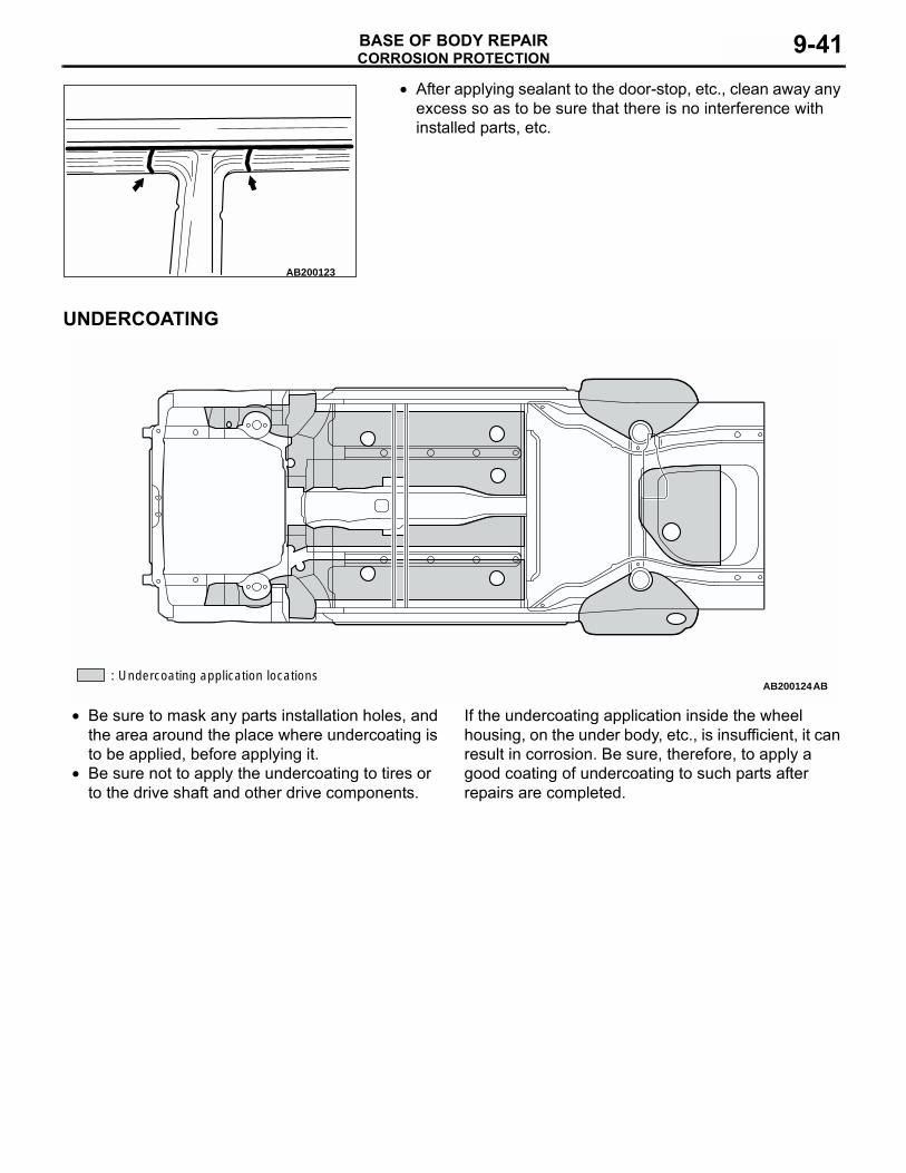
UNDERCOATING
• Be sure to mask any parts installation holes, and the area around the place where undercoating is to be applied, before applying it.
• Be sure not to apply the undercoating to tires or to the drive shaft and other drive components.
If the undercoating application inside the wheel housing, on the under body, etc., is insufficient, it can result in corrosion. Be sure, therefore, to apply a good coating of undercoating to such parts after repairs are completed.
AB200123
AB200124: Undercoating application locations
AB

NOTES