group technology chapter 10. group technology group technology is a manufacturing technique and...
TRANSCRIPT

GROUP TECHNOLOGY
Chapter 10

GROUP TECHNOLOGY
GROUP TECHNOLOGY IS A MANUFACTURING TECHNIQUE AND PHILOSOPHY TO INCREASE PRODUCTION EFFICIENCY BY EXPLOITING THE “UNDERLYING SAMENESS” OF COMPONENT SHAPE, DIMENSIONS, PROCESS ROUTE, ETC.
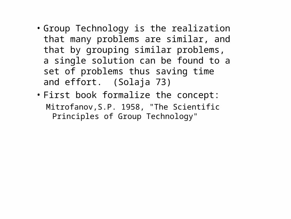
• Group Technology is the realization that many problems are similar, and that by grouping similar problems, a single solution can be found to a set of problems thus saving time and effort. (Solaja 73)
• First book formalize the concept:Mitrofanov,S.P. 1958, "The Scientific
Principles of Group Technology"

Why Group Technology?
• Average lot size decreasing• Part variety increasing• Increased variety of materials With diverse properties• Requirements for closer tolerances
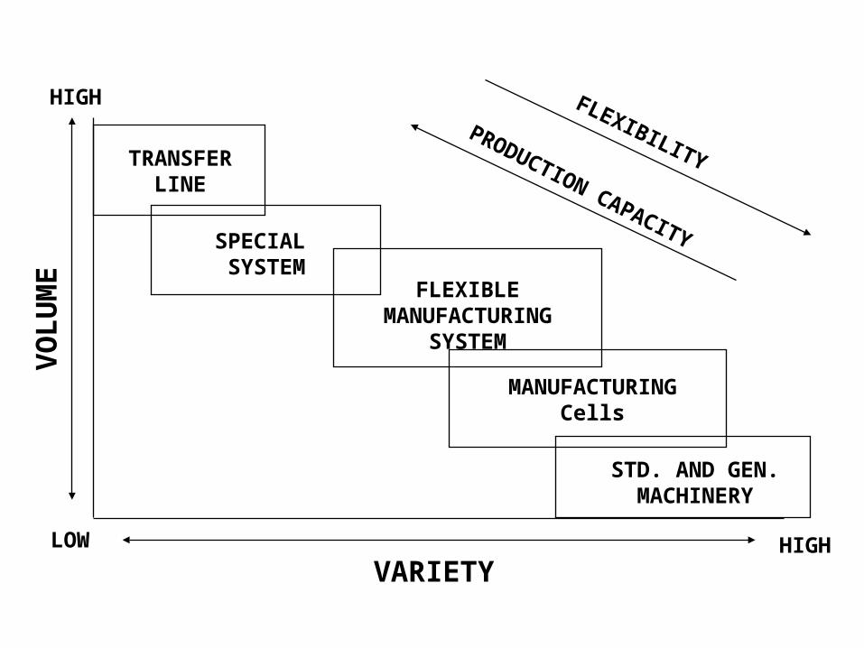
FLEXIBILITY
PRODUCTION CAPACITY
TRANSFERLINE
SPECIAL SYSTEM
FLEXIBLEMANUFACTURING
SYSTEM
MANUFACTURINGCells
STD. AND GEN.MACHINERY
VO
LU
ME
HIGH
VARIETYLOW HIGH

Everyday Examples
1. Fast food chains2. Doctors, dentists and also manufacturing
A FAMILY OF PARTS

Production Family
• Lack Of Common Database For Mfg., Design...
• Don’t “redesign the wheel”• Automated process planning• Database to drive the automated factory

Benefits Of Group TechnologyReductions in
Throughput timeSet-up timeOverdue orders
Production floor spaceRaw material stocksIn-process inventory
Capital expendituresTooling costsEngineering time and costs
New parts designNew shop drawingsTotal number of drawings
Cont’d

Other Benefits Of Group Technology
Easier to justify automation Standardization in design Data retrieval Easier, more standardized process plansIncreases in quality

Gt affects most every operating and staff function. It is more than merely a technique, but a total
Manufacturing philosophy.
GT
DESIGNENGINEERINGDATA
PROCESSING
MAINTENANCE
TOOL ENGINEERING
ESTIMATING
INDUSTRIALRELATIONS
QUALITYCONTROL
R & D
COSTACCOUNTING
SALES
INVENTORY
PLANNING
PURCHASING
ASSEMBLY
MANAGEMENT
MFG.ENGINEERING
SHIPPING &RECEIVING
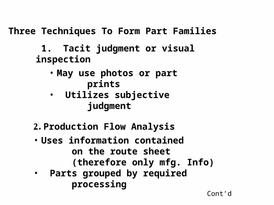
Three Techniques To Form Part Families
1. Tacit judgment or visual inspection
2. Production Flow Analysis
• May use photos or part prints• Utilizes subjective judgment
• Uses information contained on the route sheet (therefore only mfg. Info)• Parts grouped by required processing
Cont’d

3. Classification And Coding
• Codes geometry/design and mfg. Info about a component• Codes are alphanumeric strings• Easier to use for other analyses

Types Of Classification And Coding Systems
GT coding can benefit many facets of the Firm and fall into one of 3 categories:
1. Systems based on part design Attributes2. Systems based on part mfg. Attributes3. Systems based on design and mfg. Attributes

Examples:
Part Design Attributes
Basic external shapeBasic internal shapeMaterial
Part Mfg. Attributes
Major processesMinor operationsFixtures needed
Length/diameter ratio
Surface finish
Tolerances-----machine tool Operation sequence
Major dimensionTooling
Batch size

GT Code--a Sequence Of Numerical Digits
Three major structures:
1. Monocode (or hierarchical structure)
A code in which each digit amplifies the information given in the previous digit
• Difficult to construct• Provides a deep analysis• Usually for permanent information
cont’d

2. Polycode (Or Chain-type Structure)
Each digit is independent of all others, presents information not dependent On previous ones
• Easier to accommodate Change
3. Mixed Code
Has some digits forming monocodes, but strings them together in the general Arrangement of a polycode

POPULATION SPACE
CODE SPACE
P
C
MAPPING FROM POPULATION SPACE TO CODE SPACE
H

UN
F t
hre
ad
Tra
nsm
issi
on
Hierarchical Structure
Hydraulic Electrical
Mechanical
32XX
321X
322X
No
thre
adU
NC
thread
3222
323X
Power
Receiving
3232
3231 3233
3221 3223

MonocodePolycode Polycode
Hybrid Structure

Reduction Of Mfg. Costs By Various Steps Of Group Technology Applications
(Adapted From Ham442)
Improvements in Engineering Design
Materials Management & Purchasing Benefits
Production Control Benefits
Manufacturing Engineering Benefits
Tooling & Setup Benefits
Management BenefitsOverall Cost Reduction & Increased Productivity
Not All Cost Savings Are Immediate...
0 6 12 18 24 36Time (months)
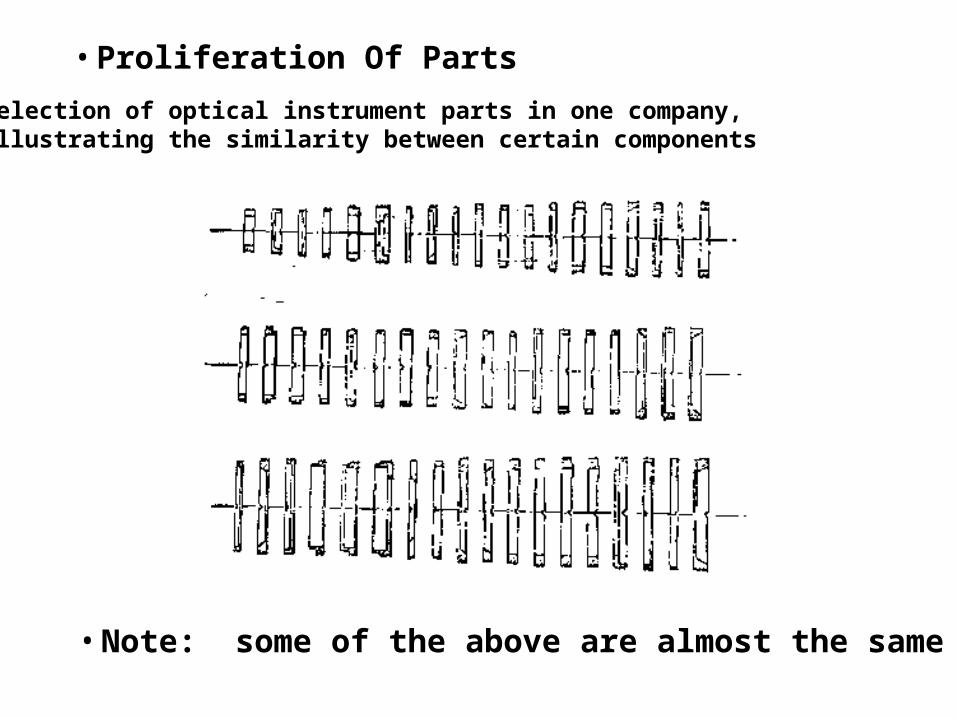
Selection of optical instrument parts in one company, Illustrating the similarity between certain components
• Proliferation Of Parts
• Note: some of the above are almost the same

Conceptual design
Coding (rough model)
Retrieval existing designs
Existing designs
Design modification
New Design
Design archive
Retrieve designs of similarshape or function and usethem as the examples.
Design concept can be coded.
Code is a rough model of theconceptual design.

Technique:
1. Determine part and machine requirements
2. Numerically code each partGeometry (& size)MaterialOther specifications (tolerance, Surface finish)
3. Form a family of similar parts which use (Largely) the same set of machine tools
4. Lay out of each cell (a group of machine Tools) to make a family of parts
5. Design group tooling

Example:
Thirteen parts with similar manufacturing Process requirements but different
Design attributes

Functional Layouts Are Inefficient
PROCESS-TYPE LAYOUT
Lathe Milling Drilling
Grinding
Assembly
Receiving andShipping
L
L L
L
L
L
L
L M
MM
M M
M
A A
A A
D
D D
D
G
G
G
G G
G

Group Technology Layout
Shipping
L L M D
L M D
G
L M GG
A A
Receiving

Department #2
Department #3
Department #1
D D M I
D ML L I
D
M
LM
I
Cellular Layout
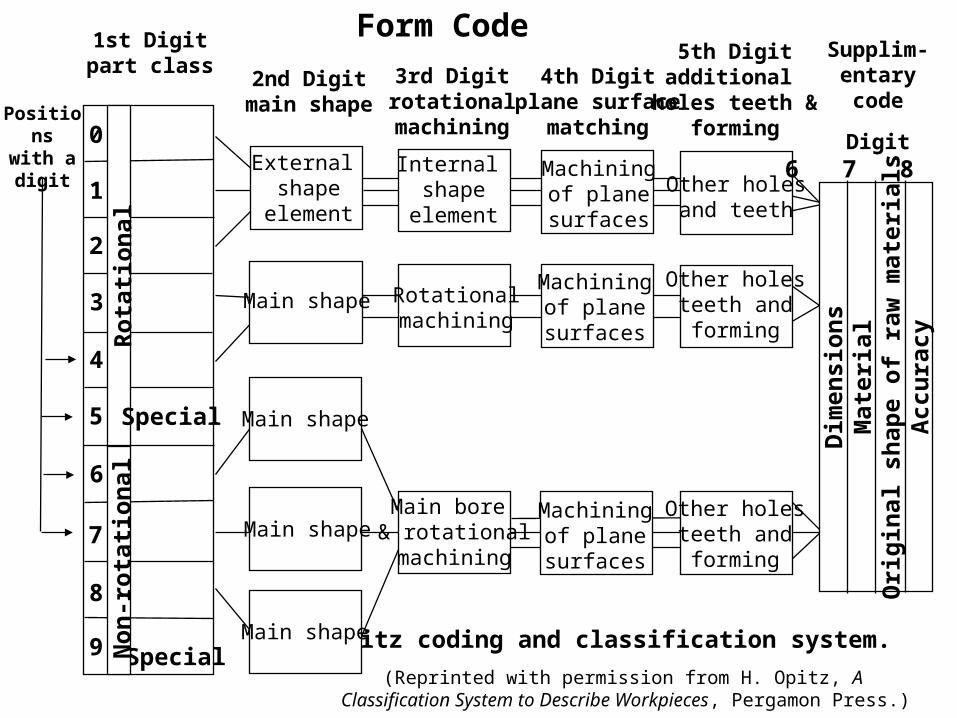
1st Digitpart class
Positionswith adigit
2nd Digitmain shape
3rd Digitrotationalmachining
4th Digitplane surface
matching
5th Digitadditional
holes teeth &forming
Form Code
Opitz coding and classification system.
(Reprinted with permission from H. Opitz, A Classification System to Describe Workpieces, Pergamon Press.)
Special
Non
-rot
atio
nal
Special
Rot
atio
nal
9
8
7
6
5
4
3
2
1
0Internal
shapeelement
Rotationalmachining
Main bore & rotationalmachining
Other holesand teeth
Other holesteeth andforming
Other holesteeth andforming
Machiningof planesurfaces
Machiningof planesurfaces
Machiningof planesurfaces
External shape
element
Main shape
Main shape
Main shape
Main shape
Supplim-entarycode
Digit6 7 8 9
Dim
ensi
ons
Mat
eria
lO
rigi
nal s
hape
of
raw
mat
eria
lsA
ccu
racy

Process planningsystem
APT Processor& post-processor
APT Program
Process
XXX
Typical Process
Planning System
Partprogramme
r
Production planner• Scheduling• MPP
Industrial engineer• Time standard• Operation instruction• Layout
Engineeringdrawing
Processplanner
Code orother form
of input
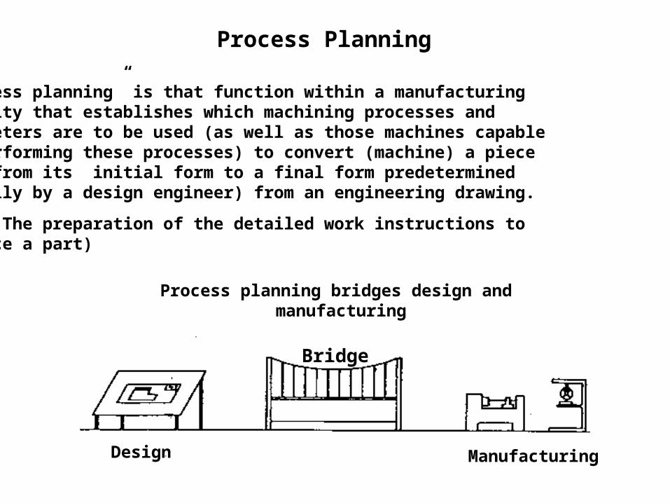
Process Planning
“Process planning” is that function within a manufacturing Facility that establishes which machining processes and Parameters are to be used (as well as those machines capable Of performing these processes) to convert (machine) a piece Part from its initial form to a final form predetermined (usually by a design engineer) from an engineering drawing.
(I.E. The preparation of the detailed work instructions to Produce a part)
Bridge
Design Manufacturing
Process planning bridges design and manufacturing

Variant Process Planning
Uses the similarity among components to retrieve existing process plans (which can be modified)
Overview: Two Stages For VP Systems
1. Preparatory stage
• Existing parts coded & classified (i.E. Gt is a prerequisite)• Part families organized• Standard plans developed• Databases created
(Note: this stage is labor intensive)Cont’d

Part Drawing
Coding
Family Formation
Process Plan
Family One
StandardPlanFile
(Indexedby FamilyMatrix)
1. Preparatory Stage Of Variant
Process Planning
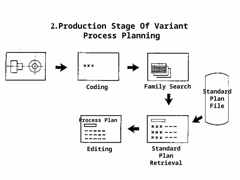
2. Production Stage Of Variant Process Planning
Coding Family SearchStandard
PlanFile
Editing Standard PlanRetrieval
Process Plan