grove & dall’olio
TRANSCRIPT

GROVE & DALL’OLIO A R C H I T E C T S pllc
18 WEST BOSCAWEN STREET • WINCHESTER, VIRGINIA 22601 • 540 -773 -2328 • . 304 267 -2120 • [email protected] • GDAaia .com
MEMORANDUM To: All Bidders From: Matthew Grove Grove & Dall'Olio Architects PLLC 304 267-2120 Date: July 21, 2020 Re: Shepherdstown Opera House Renovation ADDENDUM No. 2 The following information amends or supersedes the current issue of architectural, structural, and MEP drawings/specifications dated June 22, 2020. 1. The third floor roof deck will require new roof sheathing, insulation and roof membrane. 2. What panel are rooftop units M1 &M2 receiving their power feeds from? H2-2,4 – refer to panel schedule H2 and power plan on E1.1. 3. Where is the Fire Alarm Panel being located? Is it staying in the original spot from site visit? Lobby 101, north wall, left side near Janitor’s Closet door. 4. Is the MDP for the service being located where it is currently The new electrical service will be located on the back of the building between the back stage door and corner of the building (generally where it is currently located). There is no MDP, this will be meter stack arrangement (see Power Riser Diagram on Sheet E2.1). 5. The Contractor shall provide closet fixtures model MNSL L46 1LL by Lithonia Lighting. 6. For Fire Alarm,system , how many points will need to be monitored for the sprinkler system? The fire alarm and sprinkler systems are “design build” as indicated on E0.1. The fire alarm system design (including number of monitoring and control points) will be the responsibility of the fire alarm contractor. It will be the fire alarm contractor’s responsibility to coordinate the fire alarm design with the sprinkler system requirements. That said, fire alarm will be activated on sprinkler flow (flow switch). Also, the main sprinkler service valves will have tamper switches that will require monitoring. 7. Sheet M0.1: MECHANICAL SPECIFICATIONS – under “CODES AND STANDARDS”, change code
references to the following: 2015 INTERNATIONAL BUILDING CODE (IBC) 2015 INTERNATIONAL RESIDENTIAL CODE (IRC) 2015 INTERNATIONAL MECHANICAL CODE (IMC) 2015 INTERNATIONAL PLUMBING CODE (IPC) 2015 INTERNATIONAL ENERGY CONCERVATION CODE (IECC) 2014 NATIONAL ELECTRIC CODE (NEC) 2015 NATIONAL FIRE PROTECTION ASSOCIATION (NFPA) 101
8. Sheet M2.1: PARTIAL PLAN “B” – SUPPLY AIR DUCTS SERVING THE BAR and LOBBY AREAS;
REVISE FROM 8”X8” TO 10”X10” that drop and run in both directions.

2
9. Sheet M4.1: LINEAR BAR GRILLE SCHEDULE – CHANGE C1 TO D1 10. Sheet M4.1: RESIDENTIAL 2-WAY SUPPLY REGISTER SCHEDULE – change basis of design TO
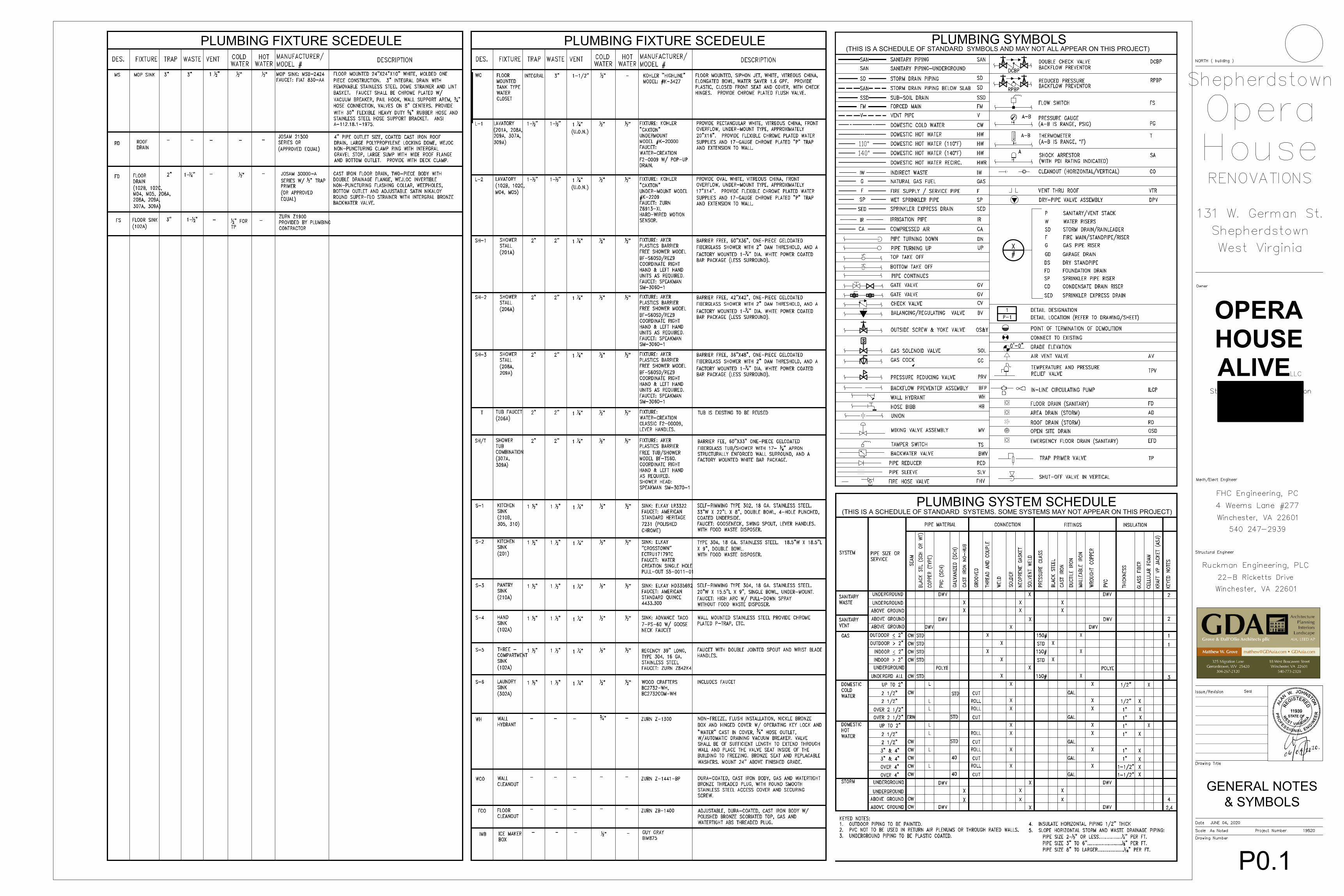
HART & COOLEY model 92VHV STEEL double deflection register with opposed blade dampers. 11. Sheet P0.1: REVISED PLUMBING FIXTURE SCHEDULE (ATTACHED) 12. Sheet P0.2: REVISED PLUMBING SPECIFICATIONS (ATTACHED) 13. Sheet P1.1: ADD FLOOR SINK IN 102A (SEE REVISED PLUMBING FIXTURE SCHEDULE) FOR
INDIRECT DRAINAGE OF THREE-COMPARTMENT SINK
14. Sheet P1.1: ADD ½” WATER LINE W/BACKFLOW PREVENTER IN 102A FOR UNDERCOUNTER ICE MAKER.
15. Sheet P1.1: ADD ¾” WATER LINE TO NEW WALL HYDRAND LOCATED BETWEEN BACK STAGE
DOOR AND STAIR C DOOR. WATER LINE SHALL BE UNDER SLAB ADJACENT TO THE NEW STORM WATER PIPING (SEE A1.2).
16. Sheet P1.1 & P1.2: Add floor drains (see revised Plumbing Fixture Schedule) in 102B, 102C, M04,
M05, 206A, 208A, 209A, 307A AND 309A). 17. SHEET P1.2: ADD WALL HYDRANT ON THIRD FLOOR ROOF DECK BEHIND DOOR TO 305. 18. SHEET P1.2: ADD LAUNDRY SINK (REFER TO REVISED PLUMBING FIXTURE SCHEDULE) IN
302A. 19. GENERAL: REFERING TO SHEET A1.2, COORDINATE INSTALLATION OF STORM WATER LINE
WITH GC. 20. GENERAL: WATER TAP IN STREET IS PART OF THIS CONTRACTOR’S SCOPE OF WORK. 21. GENERAL: Provide 1/4” water supply to refrigerators for ice makers from nearby water lines. 22. Sheet M0.1: Delete section C. under “Air Distribution” as there is no flexible ductwork on this project. 23. Provide/install sealant on concrete slabs and new concrete block work. Apply SurePoxy HM EPL as
manufactured by Kaufman. 24. Structural shoring will be required for the installation of new east side block wall and footing in the
auditorium. Other minor shoring areas may also be required. Include delegated design of the shoring. 25. All submitted RFI responses are being made available for all bidders through Addenda. 26. Finish schedule list’s Beaded Board for rooms 204,205, because it is existing and is to remain. Delete
beaded board in bathrooms 307,& 309. Also delete ceramic tile shower surrounds in rooms 307 and 309. Tub specified includes an integral shower surround.
27. Acoustic panels shown on Sheet A6.1 detail 1 may be Sonora 1” thick panel made by Acoustical
Solutions of Richmond, VA or equal. Fabric shall be Spinel(style 3582) Tiger Eye by Guilford of Maine. 28. What is a L-1, L-2, L-3 type Lavatory. See revised Plumbing Fixture Schedule
29. What is a S-1, S-2, S-3, S-4 type Sink. See revised Plumbing Fixture Schedule 30. Will there be a need for an expansion tank; if so, how many? No expansion tank(s)

3
31. Is there a preferred washer machine box. Guy Grey Model T or approved equal 32. Electrical devices shall all be brown. All device plates shall be bronze plated steel. All light fixtures shall
have dimmer switches except public bathrooms (use occupancy sensor switches for public bathrooms) and technical theater lighting. Provide Ariadni (Lutron) toggle switch with dimmer slide on side.
33. Add 3-way switch to entry corridor lights in both third floor apartments. Provide fixture 17 above shower
in room 208A. 34. Partition between Lounge and Auditorium shall be a 2x4 wall. Delete reference called out as 2x6 wall
on Structural drawing S.1. Lintel above window in this door shall be (2) 9 ¼” x 1 ¾” LVLs instead of (3) 7 ¼” x 1 ¾” LVLs.
35. Sheet E1.1: See revised (clouded) changes to electrical and power plan (ATTACHED) End Addendum No. 2

Catalog Number
Notes
Type
LED Striplight
FEATURES & SPECIFICATIONSINTENDED USE — Inspired by classic fluorescent strip channels, this LED fixture offers a traditional appearance that incorporates the latest technology. Available in several lengths and lumen packages. Ideal for use in commercial, retail, office, warehouse and display applications. Certain airborne contaminants can diminish the integrity of acrylic and/or polycarbonate. Click here for Acrylic-Polycarbonate Compatibility table for suitable uses.CONSTRUCTION — Compact-design channel and cover are formed from code-gauge cold-rolled steel. Easy to install row aligner included with 2LL versions for continuous row mounting. High-gloss, baked white enamel finish (standard).OPTICS — LEDs provided 80+ color rendering index (CRI) at 4000K. Diffuse polycarbonate lens provides smooth, linear illumination which is designed to resemble the classic look of traditional fluorescent tubes. Lumen output up to 1,150 lumens per foot.ELECTRICAL — The fixture is tested to withstand a maximum line surge of 2.5kV/.2kA ring wave for indoor locations. MVOLT versions also tested to withstand a maximum line surge of 2kV/1kA combination wave for indoor locations. For applications requiring higher level of protection, additional surge protection must be provided.INSTALLATION — Fixture may be surface or suspension mounted with appropriate mounting options. Aligner locks in place for easy continuous row mounting. Luminaire should be installed in applications where ambient temperatures do not exceed 95˚F (35˚C) for 4' and 8' models or 104˚F (40˚C) for 2' models.LISTINGS — CSA certified to US and Canadian safety standards and listed suitable for damp locations. Minimum starting temperature at -40˚F (-40˚C). Maximum ambient operating temperature of 95˚F (35˚C) for 4' and 8' models. Maximum ambient operating temperature of 104˚F (40˚C) for 2' models.WARRANTY — 5-year limited warranty. Complete warranty terms located at www.acuitybrands.com/CustomerResources/Terms_and_conditions.aspxNOTE: Actual performance may differ as a result of end-user environment and application.All values are design or typical values, measured under laboratory conditions at 25˚C.Specifications subject to change without notice.
MNSL
ORDERING INFORMATION
Catalog number Description Lumens Wattage VoltageColor
TemperatureColor Rendering
Index Pallet Quantity
MNSL L23 1LL 120V 40K 80CRI 2' 1-Light 120V LED Strip Light 1150 12 120V 40K 4000K 80CRI 80 CRI 576
MNSL L24 2LL MVOLT 40K 80CRI 2' 2-Light MVOLT LED Strip Light 2200 25 MVOLT (120-277V) 40K 4000K 80CRI 80 CRI 336
MNSL L46 1LL 120V 40K 80CRI 4' 1-Light 120V LED Strip Light 2300 25 120V 40K 4000K 80CRI 80 CRI 288
MNSL L48 2LL MVOLT 40K 80CRI 4' 2-Light MVOLT LED Strip Light 4500 50 MVOLT (120-277V) 40K 4000K 80CRI 80 CRI 168
MNSL L96 2LL MVOLT 40K 80CRI 8' 2-Light MVOLT LED Strip Light 8200 90 MVOLT (120-277V) 40K 4000K 80CRI 80 CRI 252
Lead times will vary depending on options selected. Consult with your sales representative.
MNSL_THD
INDUSTRIAL: One Lithonia Way Conyers, GA 30012 Phone: 800.315.4963 www.lithonia.com © 2016 Acuity Brands Lighting, Inc. All rights reserved. Rev. 08/23/16
PHOTOMETRICSSee www.lithonia.com.

HYDRONIC FIRE PROTECTION SYSTEM NOTES
GENERAL A.B.
Provide a complete wet pipe system of automatic sprinklers in heated areas. Conceal all piping in finished spaces except backstage & Stair C.The system shall be installed in accordance with the rules and regulations of the WV State Fire Marshal's office.
C. System piping shall be hydraulically designed throughout all areas in accordance with the rules and regulations of NFPA Pamphlet No. 13using the design densities required by code. Sprinkler system design shall accommodate a potential load of the greater density of mixed use (if applicable). Provide mains and branches designed to support head density and spacing as required by the hazard classification of the individual spaces being sprinkled.
D. The hydraulic calculations for the sprinkler system pipe sizing shall be based on the actual site residual and static pressures as measured atthe nearest fire hydrant.
E. Sprinkler piping shall be installed and coordinated with the ductwork and other mechanical and electrical services in the ceiling cavities by theContractor to provide the clearances for lighting fixtures as indicated on the drawings.
F. Provide sprinkler system with required drain lines, test connections� spare heads, tools, Siamese connections, alarms, circuit closers, monitorswitches, alarm valves. isolation valves, air compressors, etc.
G. Water Flow Alarm Switches os required by NFPA Standards.H. Supervisory Switches as required by NFPA Standards.I. The Automatic Sprinkler Design/Build Contractor will perform the final sprinkler system design, including hydraulic calculations, as required by
all applicable codes and the local Fire Marshall to accommodate this facility. The fire sprinkler contractor will prepare and provide sprinklershop drawings that have been stamped and signed by a professional engineer, liscensed in the State of Virginia, and submit them for review by the West Virginia State Fire Marshal.
CODES AND STANDARDS A. The referenced codes shall include any and all supplements, addenda, memoranda, information bulletins and any other changes and additions
effective prior to the Date of Substantial Completion by adoption of the local Authority Having Jurisdiction. B. Modifications required by the Authorities Having Jurisdiction shall be made without additional charge to the Owner.C. Where alterations to and/or deviations from the Contract Documents are required by the Authorities, report the requirements to the Architect
and secure his approval before starting the alterations.D. Where Contract Documents' requirements are in excess of Code requirements, the Contract Documents shall govern.E. All rules and regulations of the Underwriters Laboratories (UL) shall be complied with whether or not indicated in the Contract Documents.F. Provide all work in accordance with the following codes and standards:
West Virginia State Fire Code 2020National Electric Code. NFPA 101NFPA Standard #13 - Installation of Sprinkler Systems, latest edition in force. NFPA Standard /124 - Installation of Private Water Supplies, latest edition in force.
QUALITY ASSURANCE A. Basis of Design: As indicated on the drawings and as specified in Part 2 of this section.B. Acceptable Manufacturers: If they comply with these specifications, products by the following manufacturers will be acceptable.
1. Pipe and fillings: Allied Tube & Conduit, U.S. Pipe and Foundry, Victaulic.2. Valves: Mueller, Nibco, Stockham, Milwaukee, Grinell, Victaulic, Watts, Clay Valve.3. Fire department connections: Potter-Roemer, Allenco.4. Sprinkler heads: Reliable, Central, Viking.
PIPE, FITTINGS AND VALVES A. Interior Piping:
1. Interior pipe shall be new and designed for 175 psi working pressure.2. Pipe shall be black steel, conforming to ASTM A 135, Schedule 40. Schedule 40 pipe may be threaded (ANSI B 2.1), welded (ANSI B
31.10) or grooved (UL approved). 3. Schedule 10 pipe (lightwall) may be welded (ANSI B 31.10, a, b) or roll-grooved (UL approved). Lightwall pipe shall not be
cut-grooved. B. Underground Piping:
1. Ductile Iron:a. Pipe shall be Class 50 OR 51, with integrally cast bell and spigot for mechanical joints.b. Fillings shall be Class 2, short body pattern lo match spigot gland and rubber gasket on adjoining pipe or fitting.c. Joining Gaskets shall be plain rubber Type A, ANSI A 21.11 and ASTM F 36.
C. Fittings:1. Fittings shall be new and designed for 175 psi working pressure.2. Casi Iron flange fittings shall conform to ANSI B 16.1 and shall be UL approved.3. Cast iron threaded fittings shall conform to ANSI B 16.4 and shall be UL approved. Malleable iron fittings may be used on 4-inch or
smaller diameter pipe and shall conform to ANSI B 16.3 and shall be UL approved. 4. Weld fittings shall be black steel, same weight as adjoining pipe, and shall conform to ANSI B 16.9, ANSI B 16.25, ASTM A 234, ANSI B
16.5 or ANSI B 16.11.5. Grooved couplings and mechanical fittings shall be malleable iron conforming to ASTM A 47 and shall be UL approved. Gasket material
shall be EPDM or butyl rubber.E. Unions and Flanges:
1. Cast-iron flange unions shall be black standard, 175 psi working pressure WOG, UL approved, conforming to ASTM A 126 and ANSI B16.1.
2. Mechanical couplings for use with grooved pipe/fittings shall be malleable iron (conforming to ASTM A 47) or ductile iron (conformingto ASTM A 536) and shall be UL approved. Couplings shall be of hinged, two-piece design, secured in position with light fitting, heattreated carbon steel bolts and nuts (conforming to ASTM A 183). Gasket material shall be EPDM or butyl rubber.
VALVES A. Gate
1.Valves:2 inches and smaller: 200-paund WSP, bronze, OS&Y, rising stem, screwed bonnet, solid wedge disc, screwed, UL listed, ASTM A 126,Class B.
B.
C.
2. 2 1/2 inches and larger: 175-pound WOG, IBBM, OS&Y, rising stem, bolled bonnet, solid wedge disc, flanged, UL listed, ASTM A 126,Class B.
Check Valves: 1. 2-1/2 Inches and larger: 175-pound WOG, IBBM, swing, bolted cap, renewable seal, flanged, UL listed, ASTM A 126, Class B.Butterfly Valves: 1. UL listed with full lug type ductile iron body, aluminum bronze disc, 316 stainless steel stem, Buna-N seat, phenolic ring, bubble-tight
2.
closure at 175 psi and worm gear manual operator with crank or handwheel and indicator. Provide a tapped hole in gear operator casing for attachment of supervisory switch. UL listed with grooved-end design, grade "H' butyl seat, bubble-light closure al 200 psi, manual gear operafor, standard trim. Provide a tapped hole in case of gear operator for attachment of supervisory switch.
EIRE DEPARTMENT CONNECTIONS A. Provide fire department connections with local fire department standard hose threads.B. Provide fire department connections with finish selected by Architect.C. Wall-Mounted Siamese Inlet: Provide flush wall-mounted, two-way, brass body, Siamese connections at locations Indicated on the drawings.
Provide double clapper valves, plugs, chains and wall plate. Factory raised lettering label on plate shall read as indicated on the drawings.1. Basis of Design: Poller-Roemer Series #5750; or Allenco Series #270.
SPRINKLER HEADS A. Sprinkler head discharge characteristics, identification, temperature ratings, classifications and periormance shall comply with NFPA 13.B. Sprinkler heads shall have UL and FM approval.C. Provide sprinkler head orifice size as required by coverage and hydraulic calculations.D. Unless specified otherwise, provide sprinkler head finishes as follows:
1. Concealed spaces: Rough bronze.2. Unfinished spaces: Rough bronze.3. Finished spaces: Concealed.
E. Upright Type, Standard: Encapsulated, fusible alloy and spring lever actuator. Basis of Design: Reliable Model G-SSU.F. Pendent Type, Standard: Encapsulated fusible alloy and spring lever actuator. Basis of Design: Reliable Model G-SSP.G. Concealed Type: Standard pendent head of either adjustable or non-adjustable type and two-piece cup/coverplate assembly. Provide white
coverplates for heads installed in ceiling tiled spaces. Provide factory-standard coverplate finish, as selected by Architect, in all other areas.Basis of Design: Reliable Model Gl.
ACCESSORIES A. Water Flow Detector:
1. For wet sprinkler systems, provide paddle-type, clomp-on flow switch with field-adjustable retard and automatic recycle. Flow switchshall have UL label. Provide electrical characteristics compatible with Division 16 Fire Alarm System. Provide auxiliary contacts on flowswitch for connection to other building alann systems.
a. Basis of Design: Reliable Model A.B. Valve Supervisory Switch: Provide UL listed valve-mounted supervisory switch arranged to detect the open or closed position of control valve.
Provide tamper switch, required trim and electrical characteristics compatible with Division 16 Fire Alarm System. Provide auxiliary contacts forconnection to other building alarm systems. Basis of Design: Potter-Roemer, Inc. Figure #6220 Series.
C. Ball Drip: Provide cast bross automatic ball drip with 3/4-inch threaded outlet. Basis of Design: Allenco Model #2112NY; or Potter-Roemer,Inc. Model #5982.
D. Inspector's Sight Test Connection: Provide semi-steel sight test connection with glass tube and having flow equivalent to one 1/2-inchsprinkler head.
SPRINKLER HEAD TYPES A.
B.
C.
Unfinished Spaces (mechanical rooms, storage rooms, janitor's closets, other areas not having finished ceilings): Upright, pendent or sidewall type as required to provide specified coverage and maintain maximum headroom. Fial, While Ceiling Areas: Concealed type with while coverplate. Main Building Public Lobby: Concealed type with coverplale finish selected by Architect.
PIPING SUPPORTS A. Pipe supports shall conform to NFPA requirements.
PRESSURE TESTINGA. Provide pressure tests for the entire system including all tenant improvements, changes, etc., in accordance with NFPA Standard No. 13 and
local Authorities Having Jurisdiction.
GENERAL REQUIRMENTS
SECTION 15000 - GENERAL PLUMBING REQUIREMENTS PART 1 GENERAL
A. Provide under this Division complete plumbing and fire protection systems, fully adjusted, tested, and commissioned for use as indicated onthe Drawings and as specified herein.
1.2 CODES AND STANDARDS
1.3
1.4
1.5
1.6
1.7
1.8
1.9
A. Codes and standards listed herein, insofar as they apply, form a part of these Specifications, the same as if they were fully written and shallbe followed as minimum requirements. Where standards conflict, that standard with the more stringent requirements shall be applicable.Where these specifications require higher grade material or workmanship than the referenced standards, provide the highest grade of materialand workmanship specified.
B. Prior to purchase or installation, give written notice to the Architect of any materials or apparatus believed in violation of laws, ordinances,rules or regulations, or Authorities Having Jurisdiction.
C. The referenced codes shall include any and all supplements, addenda, memoranda, information bulletins and any other changes and additionseffective prior to the permit issue dale by adoption of the local Authority Having Jurisdiction.
D. Make any and all modifications required by the Authorities Hoving Jurisdiction without additional charge to the Owner.E. Where alterations to and/or deviations from the Contract Documents are required by the Authorities, report the requirements to the Architect
and secure approval before starting the alterations.F. Where Contract Documents' requirements are in excess of Code requirements and are permitted under the Code, the Contract Documents shall
govern.G. All rules and regulations of the Underwriters Laboratories shall be complied with whether or not indicated in the Contract Documents.H. All work shall comply with the following codes ond standards.
1. Codes:International Building Code, latest edition in forceInternational Plumbing Code, latest edition in forceInternational Fuel Gas Code, latest edition In forceNational Electric Code.
2. Standards: In addition to the requirements shown or specified, comply with the latest current applicable standards, specifications andcodes published by the following (where the following publications list recommendations and guidelines, the recommendations andguidelines shall be considered requirements of this contract and the items and systems shall be constructed and/or tested in accordancewith the recommendations and guidelines):
PERMITS
American Society of Mechanical Engineers (ASME).American National Standards Institute (ANSI).American Water Works (AWWA).American Society for Testing and Materials (ASTM).National Fire Protection Association (NFPA).Underwriters Laboratories {UL).Plumbing Drainage InstituteManufacturer's Standardization Society of the Valves and Fittings Industry, Inc. (t.lSS).
A. Obtain and pay for all permits, licenses, and inspection certificates required for all work in accordance with the provisions of the ContractDocuments.
GUARANTEE A. Guarnntee In form satisfactory to the Owner, that all Work Installed Is free from defects In workmanship and/or materials. Guarantee that all
apparatus will develop capacities and characteristics specified for a period of one year from the date of final acceptance by the Owner orcertification of substantial completion, whichever occurs later.
B. During the guarantee period, remedy, without cost to the Owner, defective workmanship, materials, and apparatus performance. Remedial workshall be completed within a reasonable time specified by the Owner. In default thereof, the Owner may have such work done and charge allcosts to the Contractor.
COMPLETE PERFORMANCE OF WORK A. Execute work In strict accordance with the best practice of the trades In a thorough, substantial, workmanlike manner by competent workmen.B. Provide labor, materials, apparatus, and appliances essential to the complete functioning of the systems described and Indicated, or which may
be reasonably implied as essential whether mentioned in the Contract Documents or not. C. In cases of doubt as to the Work intended, or in the event of need for explanation thereof, request supplementary instructions from the
Architect.COOPERATION WITH OTHER TRADES A. Coordinate efforts of all trades and furnish in writing, with copies to the Architect and Owner, any information necessary to permit the work
of all trades to be installed satisfactorily and with least possible interference or delay.B. Where the work of various trodes will be Installed In close proximity to one another, or where there Is evidence that the work of one trade
will interfere with work of other trades, assist in working out space conditions to make a satisfactory adjustment. If one trade installs hiswork before coordinating with work of other trades, make necessary changes to correct the condition without extra charge.
DRAWINGS A. The Drawings show the general layout of the various Items of equipment. However, layout of equipment, accessories, speclalties, ductwork,
end piping systems ore diagrammatic unless specifically dimensioned, and do not necessarily indicate every required valve, fitting, trap, duct,elbow, transition, turning vane, or similar items required for a complete installation. Consult the Architectural Drawings and details for exactlocation of rough-ins, fixtures and equipment. Where same is not definitely located, obtain the information from the Architect beforeproceeding.
B. Follow the Drawings in laying out the work and check drawings of all trades to verify spaces in which work will be installed. Maintainmaximum headroom throughout. Where space conditions appear inadequate, request clarification from the Architect before proceeding with theinstallation.
MANUFACTURER'S RECOMMENDATIONS A. Except where specifically indicated differently in the Contract Documents, apply, install, connect, erect, use, clean, and condition manufactured
articles, materials, and equipment per manufacturer's current printed recommendations. Keep copies of such printed recommendations at jobsite
SUBMITTALS A. After the Contract is awarded, but prior to proceeding with the Work, obtain complete submittals from the manufacturers, suppliers, vendors,
subcontractors, for all materials and equipment specified in this Division and submit data and details of such materials and equipment to theArchitect.
B. Prior to forwarding submittals to the Architect, review and certify that the equipment, materials, methods, etc. represented by the submittalsare in compliance with the Contract Documents.
C. A minimum period of two weeks, exclusive of transmittal time, will be required in the Engineer's office each time a submittal is submitted orresubmitted for review. This time period shall be considered by the Contractor when scheduling his work.
D. Approval of product data shall not relieve the Contractor of the responsibility for errors that may be contained therein, or for deviations fromrequirements in the Contract Documents. It shall be clearly understood that the Architect or Engineer noting some errors but overlookingothers does not grant the Contractor permission to proceed in error. Regardless of any information contained in the product data theContract Documents shall govern the work and are neither waived nor superseded In any way by submittal review.
PART 2 PRODUCTS 2.1 MATERIALS
A. The word "Provide" is defined as requiring the Contractor to "furnish, erect, test, adjust and install complete and ready for use" the item to which it refers.
B.
C.
Unless otherwise specified, provide new, first-class quality materials and apparatus required for the work. Furnish, deliver, erect, connect andfinish work in every detail, and select and arrange work to lit properly into the building spaces. Where no specific kind or quality ofmaterial is given, provide a first class standard article as approved by the Architect.Equipment designated as "Basis of Design" has been coordinated for structural penetrations; duct, piping, and electrical connection; operatingand service (maintenance) requirements; and physical size with regard to space where equipment is housed. Other specified manufacturers oflike equipment are acceptable contingent on the Contractor providing a complete installation and maintaining full responsibility to provide, at noadditional cost, any modifications to the structure or configuration of adjoining equipment and the installation that is required to properlyinstall, operate, and service the equipment being used.
PART 3 EXECUTION 3.1 EXCAVATION AND BACKFILLING
3.2
A.
B.
C.
General: Provide excavation and backfilling of trenches required for the installation of all utility services and underground piping within the building, and to points of connection with exterior underground utilities outside of the building. Trenching: Excavate to the required depths and grade the bottoms of trenches to secure the required slope for pipe llnes. Where encountered, excavate rock to a minimum depth of six inches below the botiom of pipe. Excavate lhe bottom of the trench by hand to provide firm, uniform bearing for the bottom quarter of the pipe. Excavate recesses for joints for pipe having bells, sleeves, other enlargement at the joints. Provide separate trenches for water and sewer lines. Backfilling: Do not backfill trenches until tho piping has boon tested as required and reviewed and approved by tho Architect and/or any Local Authorities having jurisdiction thereof. 1. Provide backfill consisting of sand or selected excavated material, placed to a depth of one loot above the lop of the conduit or pipe
and compacted by hand tamping. Provide backfill for the remainder of the trench in accordance with the requirements of Division 2,using materials as specified therein, and compact as required to produce the specified density.
SLEEVES, FORMED OPENINGS, PLATES, AND INSERTS A. Provide sleeves for all piping passing through masonry, concrete, tile and gypsum wall construction.B. Provide sleeves and formed openings of sufficient size to pass continuous, uninterrupted insulation of the specified thickness.C. Check floor and wall construction finishes to determine proper length of sleeves for various locations and make actual lengths to suit the
following.
D.
A.
1. Terminate sleeves flush with walls, partitions, and ceilings.2. In areas where pipes are exposed, extend sleeves 2 inches above finished floor.3.3 RECORD DRAWINGS Maintain at the project site a complete set of "Record Drawings" reflecting an accurate as-built record of all Work. In addition, mark the "Record Drawings" to show changes and deviations in the Work from that shown on the Contract Documents. This requirement shall not be construed as authorization for the Contractor to make changes in the layout or work without definite instructions from the Architect.
NORTH ( building )
thepherdstown
Opero House RENOVATIONS
131 W. Germon St.
Owner
Shepherdstown
West Virginia
OPERA
HOUSE
ALIVE C
Stl 1 111 111 1111 111 111 1 1111 1 1 1 11 111 111 1 1111 11 !! ! 111 111 11111 ;:,111 ,;; 1'1 II .:,; I ,I II l! 1 'ii
Mech/Elect Engineer
FHC Engineering, PC
4 Weems Lane #277
Winchester, VA 22601
540 247-2939
Structural Engineer
Ruckman Engineering, PLC
22-B Ricketts Drive
Winchester, VA 22601
GDA :t:
Matthew W. Gro"�
J.25 Migr,11ion Lane Gerr.ucttown, VN 25420
J04--207-1120
Issue/Revision Seal
Drawing Title
®
Archilecture Planning Interiors
Landscape
DAau:i
18 Wcsl Boscawen Street Wm,chester, VA 22&0 I
540-773-2128
•""'""""••· ,,,,,, -,N. JOH_''••,,
lt � ........... ,. l'\,o''',,, /.-J'.-··'i:,,1S T€4, .. ,,_o\
f ..; ('o:-
<,;
11939 "'J\ �, =--o· :a:::r Sc,>\ ... STAT�F i4J; -;. 0 ·-�('. -:-,.'(',• "'::; "\. -:.i:-�·•,'!r v t.l � !
..... '"&
�--. ..
•' C, � .. ,,,,,, S1 N LY:,.�,,,•• .,, ,, ..
' "'"\ ""'\
SPECIFICATIONS
Date JUNE 04, 2020
Scola As Noted
Drawing Number
Project Number
P0.2
19820

Popcorn& Ice
UP
2468
HandWash
SINK x3
UP
UP
UP
UP
DN
-0' 1/4"
Stair C S3
S3S
SS
S
S
SS
S3
S
S
S3
SDSD
abSDSD
cdSD
SDfg
SD SDa b
SD SDc d
SD SDe f
SDe
3
SDh
3
SDh
3
SDk
SDh
SDe
SS
SDg
SD
SDk
3
hSD
k
3
3
S3S3
SS 3
SSSS
SDSD
SD
2LE7
6 525
SD2
SDLE
SD5
4
S4
SD7
S5
S8
8
S25S6
S
DD D
D
D3D
D D
D
D
DD
D
Popcorn& Ice
UP
2468
HandWash
SINK x3
UP
UP
UP
UP
DN
-0' 1/4"
OPERAHOUSEALIVE
MAIN LEVEL AND MEZZANINE PLANS - POWERSCALE: 316" = 1'-0"
MAIN LEVEL AND MEZZANINE PLANS - LIGHTINGSCALE: 316" = 1'-0"
MAIN LEVEL &MEZZANINE PLANS
E1.1
PROJ. BOOTHM02
HALLM03
GALLERYM06
SOUNDM07
MEZZ. STAIRM01
STAIR A
TOILETM04
TOILETM05
PROJ. BOOTHM02
HALLM03
GALLERYM06
SOUNDM07
MEZZ. STAIRM01
STAIR A
TOILETM04
TOILETM05
LOUNGE102
LOBBY101
BAR102A
TOILET102C
TOILET102B
STAIR A