grove gmk l - tessier lteetessierltee.com/.../uploads/2015/07/13-26_grove-gmk6350l.pdf ·...
TRANSCRIPT
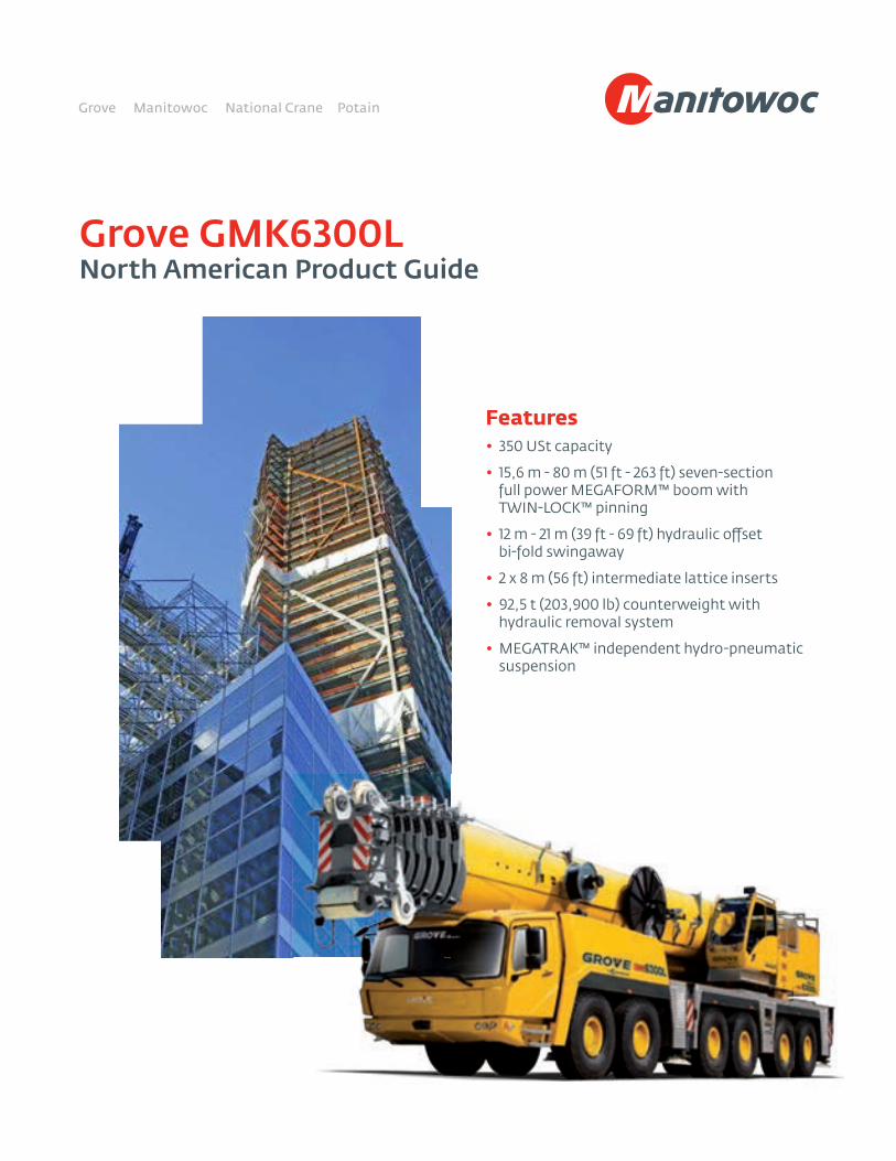
Grove GMK6300L North American Product Guide
Features• 350 USt capacity
• 15,6 m - 80 m (51 ft - 263 ft) seven-section full power MEGAFORM™ boom with TWIN-LOCK™ pinning
• 12 m - 21 m (39 ft - 69 ft) hydraulic o�set bi-fold swingaway
• 2 x 8 m (56 ft) intermediate lattice inserts
• 92,5 t (203,900 lb) counterweight with hydraulic removal system
• MEGATRAK™ independent hydro-pneumatic suspension
2
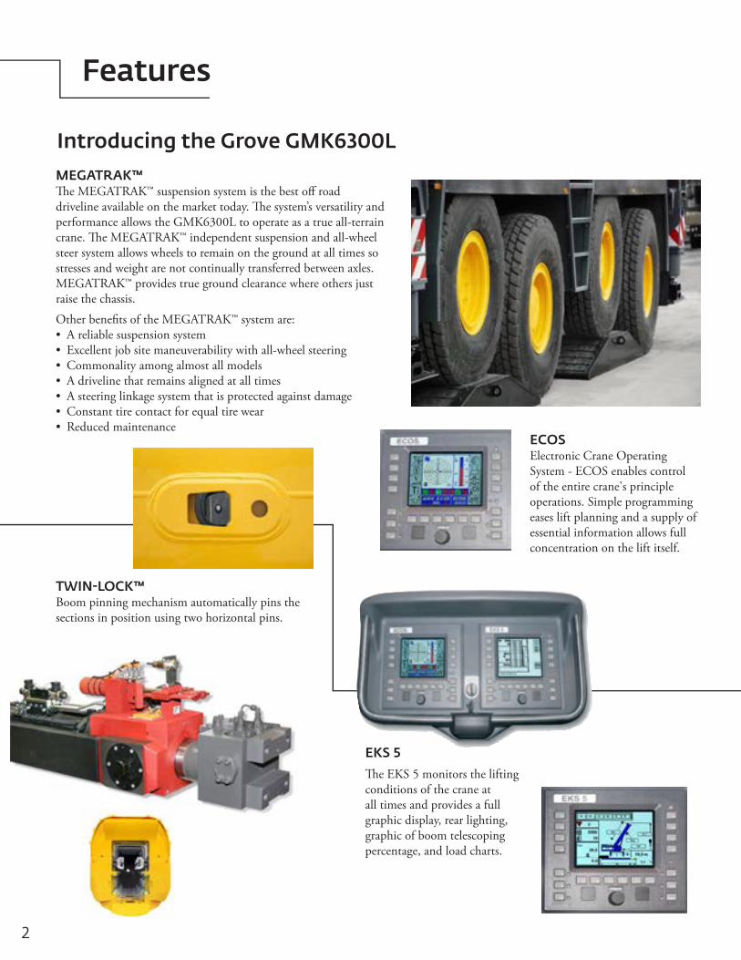
EKS 5 �e EKS 5 monitors the lifting conditions of the crane at all times and provides a full graphic display, rear lighting, graphic of boom telescoping percentage, and load charts.
MEGATRAK™�e MEGATRAK™ suspension system is the best o� road driveline available on the market today. �e system’s versatility and performance allows the GMK6300L to operate as a true all-terrain crane. �e MEGATRAK™ independent suspension and all-wheel steer system allows wheels to remain on the ground at all times so stresses and weight are not continually transferred between axles. MEGATRAK™ provides true ground clearance where others just raise the chassis.
Other bene�ts of the MEGATRAK™ system are:• Areliablesuspensionsystem• Excellentjobsitemaneuverabilitywithall-wheelsteering• Commonalityamongalmostallmodels• Adrivelinethatremainsalignedatalltimes• Asteeringlinkagesystemthatisprotectedagainstdamage• Constanttirecontactforequaltirewear• Reducedmaintenance
ECOSElectronicCraneOperatingSystem-ECOSenablescontrolof the entire crane's principle operations. Simple programming eases lift planning and a supply of essential information allows full concentration on the lift itself.
TWIN-LOCK™Boom pinning mechanism automatically pins the sections in position using two horizontal pins.
Features
Introducing the Grove GMK6300L
Specifications 4
Dimensions 7
Weights 8
Counterweight 9
Working range (main boom) 10
Load charts (main boom) 11
Working range (O�settable swingaway) 16
Load charts (O�settable swingaway) 17
Working range (O�settable swingaway with inserts) 19
Load charts (O�settable swingaway with inserts) 20
Working range (Hydraulic lu�ng jib) 22
Load charts (Hydraulic lu�ng jib) 23
Symbols glossary 25
Contents

4 *Denotes optional equipment
Specifications
15,6 m - 80 m (51 ft - 263 ft) 7-section, full power MEGAFORM™boomwithTWIN-LOCK™Pinning.Maximum tip height: 83 m (272 ft).
Nine nylatron sheaves, mounted on heavy duty tapered roller bearings with removable pin-type rope guards. Quick reeve boom nose. Removable auxiliary boom nose with removable pin type rope guard.
Single lift cylinder with safety valve provides boom angle from -1.5° to +83°.
Boom
Boom nose
Boom elevation
*Hydraulic offsettable lattice extension
12 m - 21 m (39 ft – 69 ft) bi-fold lattice swingaway extension, hydraulically offsettable and luffing under load, 5°- 40°. Maximum tip height: 104 m (341 ft)
*Lattice inserts
2 x 8 m (26 ft) inserts for use with lattice swingaway extension to increase length to 37 m (121 ft).Maximum tip height: 120 m (393 ft)
Load moment and anti-two block system with audio/visual warning and control lever lockout provides electronic display of boom angle, length, radius, tip height, relative load moment, maximum permissible load, load indication and warning of impending two-block condition.
Load moment and anti-two block system
All aluminum constructed cab with acoustical lining, hydraulic tilted to 20°. Includes tinted safety glass, adjustable operator’s seat, opening windows at side and rear, hinged windshield with wiper, sun visor and window shade. Other features include hot water heater/defroster, armrest integrated crane controls, ergonomicallyarrangedinstrumentationandradio/CDplayer.
Cab
3 planetary gear boxes with fixed displacement axial piston motors. Infinitely variable to 1.3 rpm. Free swing or hydrostatically engaged brake controlled by swing lever. Swing brake selected by foot operated switch.
Swing
92,5 t (203,900 lb) consisting of various sections with hydraulic installation/removal system controlled from the superstructure cab.
Counterweight
Mercedes OM 926 LA six-cylinderHorsepower: 210 kW (286 bhp) at 2200 rpmTorque:1120Nm(826ft/lb)at1400rpmEngineemissions:EPA/CARB/EUROMOT(offroad)
Engine
300 L (79 gal)
Fuel tank capacity
3 phase alternator: 28V/80A2 batteries: 12V/170Ah
Electrical system
2 (two) separate circuits, 1 (one) axial piston variable displacement pump (load sensing) with electronic power limiting control for crane functions and 1 (one) double gear pump for slewing. Thermostatically controlled oil coolers keep oil at optimum operating temperature.Hydraulic tank capacity: 1200 L (317 gal)
Hydraulic system
Superstructure
Work lights, mounted on boom base section Boom mounted aircraft warning light
Air conditioningHook blocks/headache ballEngine independent diesel cab heater, with engine pre-heater. Includes 24 hour timer.Datalogger360°NYCswinglock2 m (6.6 ft) side stowed heavy duty jib with 38 t (84,000 lb) maximum capacity using four parts of line,
offset 8° and 30°Cameraforboomhead
5Grove GMK6300L *Denotes optional equipment
Specifications
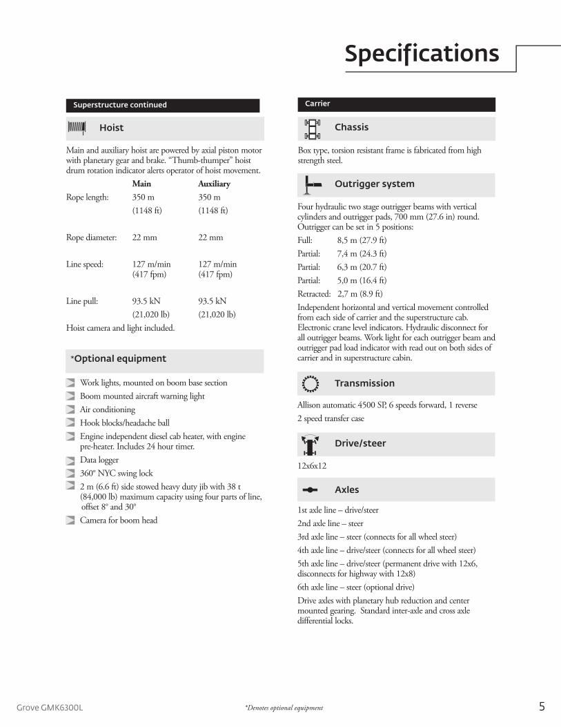
Main and auxiliary hoist are powered by axial piston motor with planetary gear and brake. “Thumb-thumper” hoist drum rotation indicator alerts operator of hoist movement.
Main AuxiliaryRope length: 350 m 350 m
(1148 ft) (1148 ft)
Rope diameter: 22 mm 22 mm
Line speed: 127 m/min 127 m/min (417 fpm) (417 fpm)
Line pull: 93.5 kN 93.5 kN (21,020 lb) (21,020 lb)
Hoist camera and light included.
Hoist
*Optional equipment
Carrier
Box type, torsion resistant frame is fabricated from high strength steel.
Chassis
Four hydraulic two stage outrigger beams with vertical cylinders and outrigger pads, 700 mm (27.6 in) round. Outrigger can be set in 5 positions:Full: 8,5 m (27.9 ft)Partial: 7,4m(24.3ft)Partial: 6,3m(20.7ft)Partial: 5,0m(16.4ft)Retracted: 2,7 m (8.9 ft) Independent horizontal and vertical movement controlled from each side of carrier and the superstructure cab. Electronic crane level indicators. Hydraulic disconnect for all outrigger beams. Work light for each outrigger beam and outrigger pad load indicator with read out on both sides of carrier and in superstructure cabin.
Outrigger system
Allisonautomatic4500SP,6speedsforward,1reverse2 speed transfer case
Transmission
12x6x12
Drive/steer
1st axle line – drive/steer2nd axle line – steer3rd axle line – steer (connects for all wheel steer)4th axle line – drive/steer (connects for all wheel steer)5th axle line – drive/steer (permanent drive with 12x6, disconnects for highway with 12x8)6th axle line – steer (optional drive)Driveaxleswithplanetaryhubreductionandcentermounted gearing. Standard inter-axle and cross axle differential locks.
Axles
Superstructure continued
6 *Denotes optional equipment
Specifications
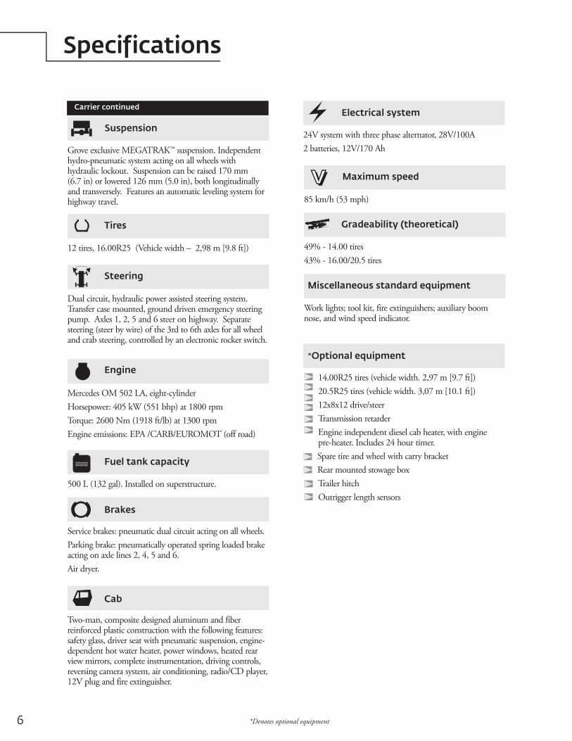
12 tires, 16.00R25 (Vehicle width – 2,98 m [9.8 ft])
Tires
Carrier continued
Dualcircuit,hydraulicpowerassistedsteeringsystem.Transfer case mounted, ground driven emergency steering pump. Axles 1, 2, 5 and 6 steer on highway. Separate steering (steer by wire) of the 3rd to 6th axles for all wheel and crab steering, controlled by an electronic rocker switch.
Steering
Mercedes OM 502 LA, eight-cylinderHorsepower: 405 kW (551 bhp) at 1800 rpmTorque:2600Nm(1918ft/lb)at1300rpmEngineemissions:EPA/CARB/EUROMOT(offroad)
Engine
500 L (132 gal). Installed on superstructure.
Fuel tank capacity
Service brakes: pneumatic dual circuit acting on all wheels. Parkingbrake:pneumaticallyoperatedspringloadedbrakeacting on axle lines 2, 4, 5 and 6.Air dryer.
Brakes
Two-man, composite designed aluminum and fiber reinforced plastic construction with the following features: safety glass, driver seat with pneumatic suspension, engine-dependent hot water heater, power windows, heated rear view mirrors, complete instrumentation, driving controls, reversingcamerasystem,airconditioning,radio/CDplayer,12V plug and fire extinguisher.
Cab
24V system with three phase alternator, 28V/100A2 batteries, 12V/170 Ah
Electrical system
85 km/h (53 mph)
Maximum speed
49% - 14.00 tires43% - 16.00/20.5 tires
Gradeability (theoretical)
Work lights; tool kit, fire extinguishers; auxiliary boom nose, and wind speed indicator.
Miscellaneous standard equipment
*Optional equipment
14.00R25 tires (vehicle width. 2,97 m [9.7 ft])20.5R25 tires (vehicle width. 3,07 m [10.1 ft])12x8x12 drive/steerTransmission retarder Engine independent diesel cab heater, with engine pre-heater. Includes 24 hour timer.Spare tire and wheel with carry bracketRear mounted stowage box Trailer hitchOutrigger length sensors
Grove exclusive MEGATRAK™ suspension. Independent hydro-pneumatic system acting on all wheels with hydraulic lockout. Suspension can be raised 170 mm (6.7 in) or lowered 126 mm (5.0 in), both longitudinally and transversely. Features an automatic leveling system for highway travel.
Suspension
7Grove GMK6300L
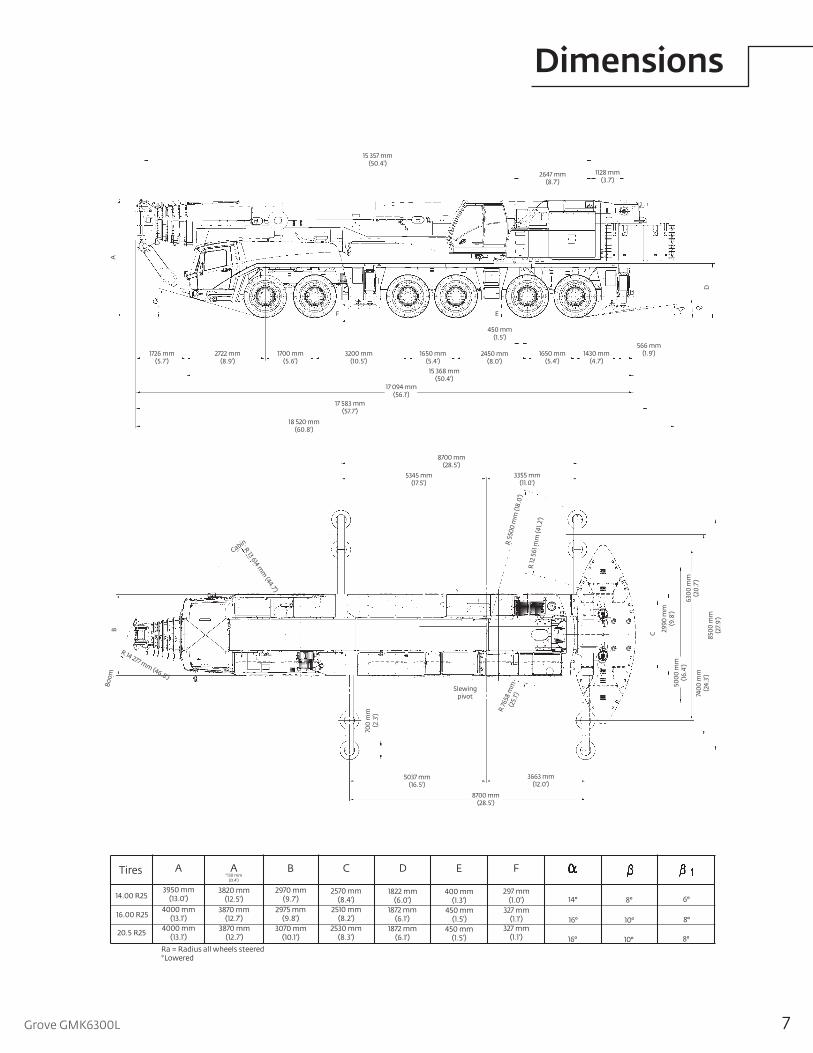
DimensionsA
450 mm(1.5')
566 mm(1.9')
F E
D
15 357 mm(50.4')
2647 mm(8.7')
1128 mm(3.7')
1430 mm(4.7')
1650 mm(5.4')
2450 mm(8.0')
1650 mm(5.4')
3200 mm(10.5')
1700 mm(5.6')
2722 mm(8.9')
1726 mm(5.7')
17 094 mm(56.1')
17 583 mm(57.7')
18 520 mm(60.8')
15 368 mm(50.4')
Tires D EBA*130 mm
(0.4')
A C F
14.00 R25
20.5 R25
16.00 R25
3950 mm (13.0')
4000 mm(13.1')
4000 mm (13.1')
3820 mm (12.5')
3870 mm (12.7')
3870 mm (12.7')
2970 mm (9.7')
3070 mm(10.1')
2975 mm (9.8')
2570 mm (8.4')
2530 mm (8.3')
2510 mm (8.2')
1822 mm (6.0')
1872 mm (6.1')
1872 mm (6.1')
400 mm (1.3')
450 mm (1.5')
450 mm (1.5')
297 mm (1.0')
327 mm (1.1')
327 mm (1.1')
14°
16°
16°
8°
10°
10°
6°
8°
8°Ra = Radius all wheels steered*Lowered
C
8700 mm(28.5')
B
5345 mm(17.5')
3355 mm(11.0')
5037 mm(16.5')
3663 mm(12.0')
8700 mm(28.5')
2990
mm
(9.8
')50
00 m
m(1
6.4'
)63
00 m
m(2
0.7')
7400
mm
(24.
3')
8500
mm
(27.
9')
R 13 614 mm
(44.7')
R 14 277 mm (46.8')
Slewing pivot
700
mm
(2.3
')
R 76
58 m
m(2
5.1')
R 5
500
mm
(18.
0')
R 12
561
mm
(41.
2')
Cabin
Boo
m
1384 mm(4.5')
1384 mm(4.5')
5150 mm(16.9')
1650 mm(5.4')
2450 mm(8.0')
1650 mm(5.4')
3200 mm(10.5')
1700 mm(5.6')
1726 mm(5.7')
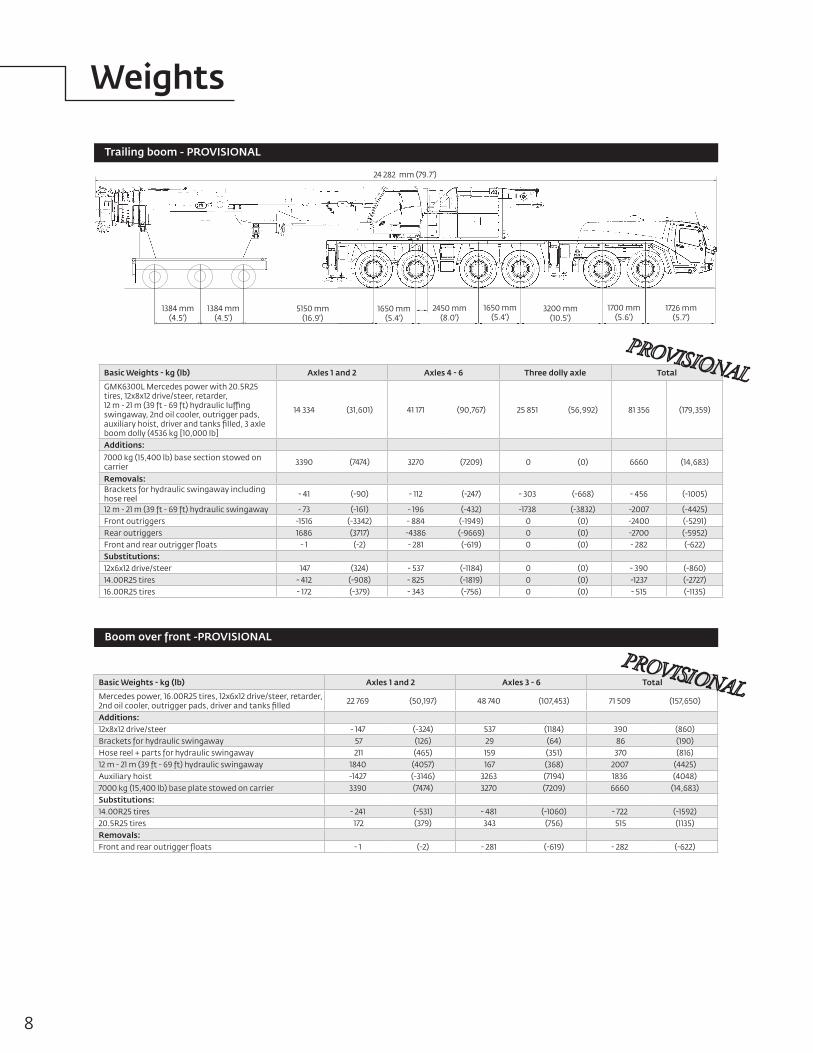
24 282 mm (79.7')
8
Basic Weights - kg (lb) Axles 1 and 2 Axles 3 - 6 Total
Mercedes power, 16.00R25 tires, 12x6x12 drive/steer, retarder, 2nd oil cooler, outrigger pads, driver and tanks filled 22 769 (50,197) 48 740 (107,453) 71 509 (157,650)
Additions:12x8x12 drive/steer - 147 (-324) 537 (1184) 390 (860)Brackets for hydraulic swingaway 57 (126) 29 (64) 86 (190)Hose reel + parts for hydraulic swingaway 211 (465) 159 (351) 370 (816)12 m - 21 m (39 ft - 69 ft) hydraulic swingaway 1840 (4057) 167 (368) 2007 (4425)Auxiliary hoist -1427 (-3146) 3263 (7194) 1836 (4048)7000 kg (15,400 lb) base plate stowed on carrier 3390 (7474) 3270 (7209) 6660 (14,683)Substitutions:14.00R25 tires - 241 (-531) - 481 (-1060) - 722 (-1592)20.5R25 tires 172 (379) 343 (756) 515 (1135)Removals:Front and rear outrigger floats - 1 (-2) - 281 (-619) - 282 (-622)
Weights
Trailing boom - PROVISIONAL
Basic Weights - kg (lb) Axles 1 and 2 Axles 4 - 6 Three dolly axle Total
GMK6300L Mercedes power with 20.5R25 tires, 12x8x12 drive/steer, retarder, 12 m - 21 m (39 ft - 69 ft) hydraulic luffing swingaway, 2nd oil cooler, outrigger pads, auxiliary hoist, driver and tanks filled, 3 axle boom dolly (4536 kg [10,000 lb]
14 334 (31,601) 41 171 (90,767) 25 851 (56,992) 81 356 (179,359)
Additions:7000 kg (15,400 lb) base section stowed on carrier 3390 (7474) 3270 (7209) 0 (0) 6660 (14,683)
Removals:Brackets for hydraulic swingaway including hose reel - 41 (-90) - 112 (-247) - 303 (-668) - 456 (-1005)
12 m - 21 m (39 ft - 69 ft) hydraulic swingaway - 73 (-161) - 196 (-432) -1738 (-3832) -2007 (-4425)Front outriggers -1516 (-3342) - 884 (-1949) 0 (0) -2400 (-5291)Rear outriggers 1686 (3717) -4386 (-9669) 0 (0) -2700 (-5952)Front and rear outrigger floats - 1 (-2) - 281 (-619) 0 (0) - 282 (-622)Substitutions:12x6x12 drive/steer 147 (324) - 537 (-1184) 0 (0) - 390 (-860)14.00R25 tires - 412 (-908) - 825 (-1819) 0 (0) -1237 (-2727)16.00R25 tires - 172 (-379) - 343 (-756) 0 (0) - 515 (-1135)
Boom over front -PROVISIONAL
9Grove GMK6300L
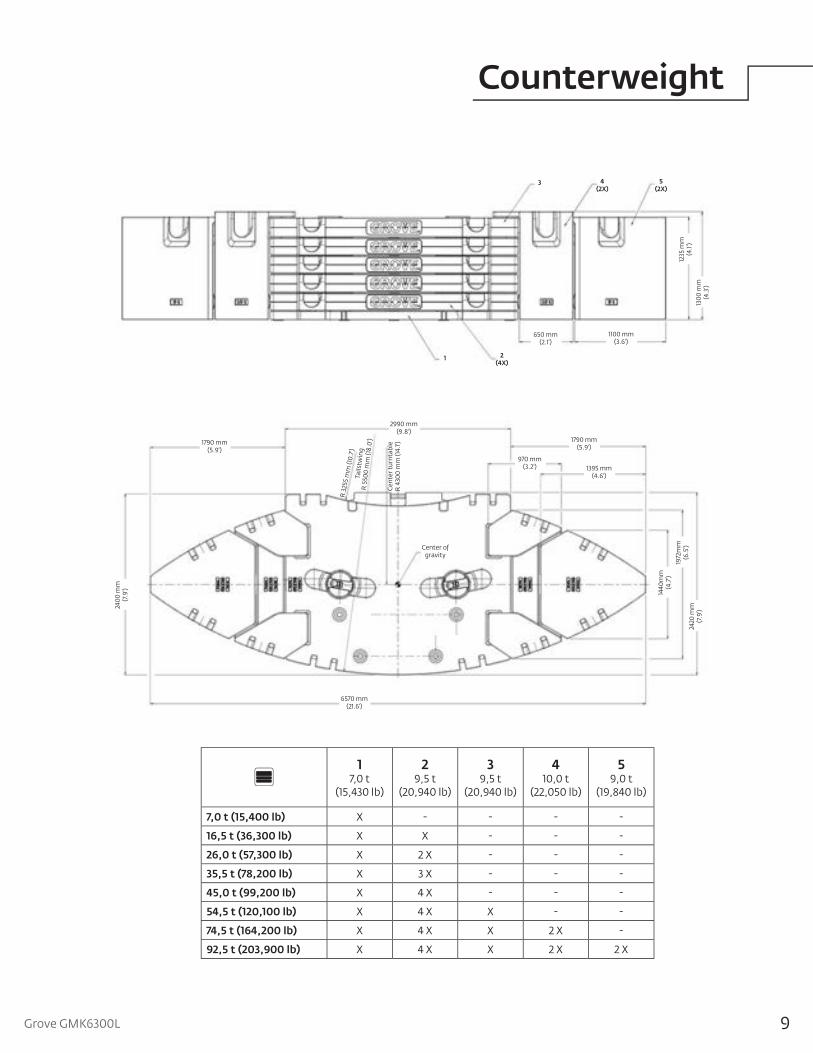
Counterweight
Counterweight
17,0 t
(15,430 lb)
29,5 t
(20,940 lb)
39,5 t
(20,940 lb)
410,0 t
(22,050 lb)
59,0 t
(19,840 lb)
7,0 t (15,400 lb) X - - - -
16,5 t (36,300 lb) X X - - -
26,0 t (57,300 lb) X 2 X - - -
35,5 t (78,200 lb) X 3 X - - -
45,0 t (99,200 lb) X 4 X - - -
54,5 t (120,100 lb) X 4 X X - -
74,5 t (164,200 lb) X 4 X X 2 X -
92,5 t (203,900 lb) X 4 X X 2 X 2 X
650 mm(2.1')
1100 mm(3.6')
1235
mm
(4.1'
)13
00 m
m(4
.3')
1 2(4X)
3 4(2X)
5(2X)
2990 mm(9.8')
1790 mm(5.9')
1790 mm(5.9')
970 mm(3.2') 1395 mm
(4.6')
6570 mm(21.6')
2400
mm
(7.9
') 1440
mm
(4.7
')19
72m
m(6
.5')
2420
mm
(7.9
')
Center of gravity
R 3
255
mm
(10.
7')Ta
ilstw
ing
R
550
0 m
m (1
8.0'
)
Cen
ter t
urnt
able
R 4
300
mm
(14.
1')
10
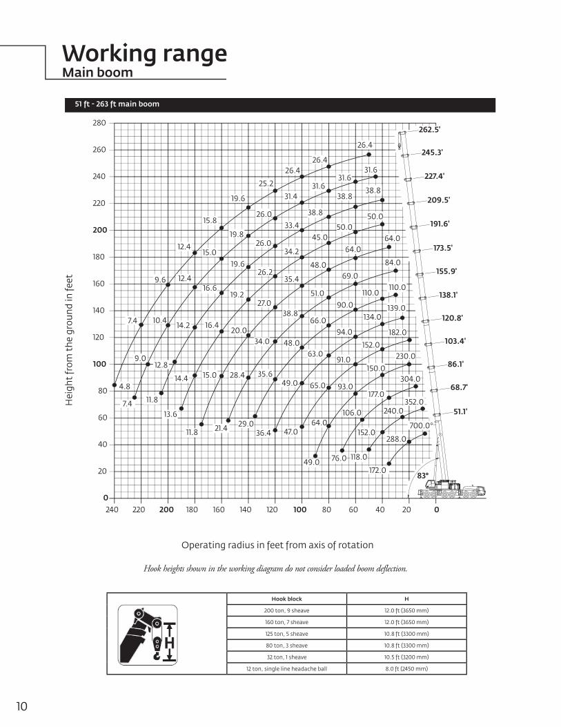
Working rangeMain boom
51 ft - 263 ft main boom
Hook heights shown in the working diagram do not consider loaded boom deflection.
Hei
ght
from
the
gro
und
in fe
et
Operating radius in feet from axis of rotation
Hook block H
200 ton, 9 sheave 12.0 ft (3650 mm)
160 ton, 7 sheave 12.0 ft (3650 mm)
125 ton, 5 sheave 10.8 ft (3300 mm)
80 ton, 3 sheave 10.8 ft (3300 mm)
32 ton, 1 sheave 10.5 ft (3200 mm)
12 ton, single line headache ball 8.0 ft (2450 mm)
240 220 200 180 160 140 120 100 80 60 40 20 0
20
0
40
60
80
100
120
140
160
180
200
220
240
260
280
51.1'
68.7'
86.1'
103.4'
120.8'
138.1'
155.9'
173.5'
191.6'
209.5'
227.4'
245.3'
262.5'
83°
31.6
31.6
26.4
25.231.6
31.4
26.426.4
26.0
26.0
19.8
19.6
33.415.8 50.0
50.045.0
34.2
38.838.8
38.8
64.0
48.0
35.426.2
19.6 84.0
69.0
51.0
64.0
27.0
16.6
38.8
19.2
15.012.4
9.6 12.4110.0
110.0
66.0
48.0
90.0
34.020.0
16.414.210.47.4
139.0134.0
94.0
63.012.8
9.0
11.87.4
4.8
21.411.8
14.4
13.6
49.0
36.4
35.6
29.0
28.415.0
106.0
76.0
93.0
64.0
49.0
65.0
47.0288.0
172.0
152.0
118.0
700.0*
352.0240.0
304.0
177.0
230.0
150.0
182.0
152.0
91.0
11Grove GMK6300L
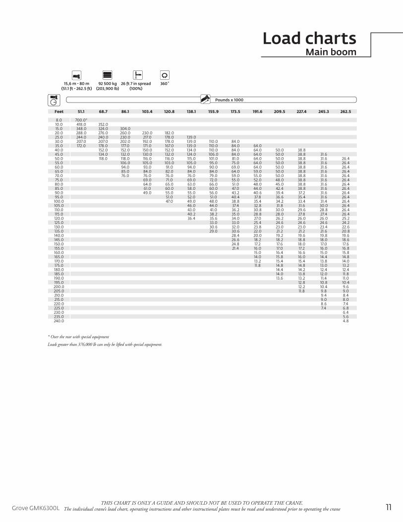
Load chartsMain boom
THIS CHART IS ONLY A GUIDE AND SHOULD NOT BE USED TO OPERATE THE CRANE. The individual crane’s load chart, operating instructions and other instructional plates must be read and understood prior to operating the crane
OutriggersCounterweight
15,6 m - 80 m 92 500 kg 26 ft 7 in spread 360˚ (51.1 ft - 262.5 ft) (203,900 lb) (100%)
Pounds x 1000Boom Extension
Feet 51.1 68.7 86.1 103.4 120.8 138.1 155.9 173.5 191.6 209.5 227.4 245.3 262.5
8.0 700.0*10.0 418.0 352.015.0 348.0 324.0 304.020.0 288.0 276.0 260.0 230.0 182.025.0 244.0 240.0 230.0 217.0 178.0 139.030.0 207.0 207.0 202.0 192.0 178.0 139.0 110.0 84.035.0 172.0 178.0 177.0 171.0 167.0 139.0 110.0 84.0 64.040.0 152.0 152.0 150.0 152.0 134.0 110.0 84.0 64.0 50.0 38.845.0 134.0 132.0 130.0 132.0 124.0 106.0 84.0 64.0 50.0 38.8 31.650.0 118.0 118.0 116.0 116.0 115.0 101.0 81.0 64.0 50.0 38.8 31.6 26.455.0 106.0 105.0 103.0 105.0 95.0 75.0 64.0 50.0 38.8 31.6 26.460.0 94.0 93.0 91.0 94.0 90.0 69.0 64.0 50.0 38.8 31.6 26.465.0 85.0 84.0 82.0 84.0 84.0 64.0 59.0 50.0 38.8 31.6 26.470.0 76.0 76.0 76.0 76.0 79.0 59.0 55.0 50.0 38.8 31.6 26.475.0 69.0 71.0 69.0 72.0 55.0 52.0 48.0 38.8 31.6 26.480.0 64.0 65.0 63.0 66.0 51.0 48.0 45.0 38.8 31.6 26.485.0 61.0 60.0 58.0 60.0 47.0 44.0 42.4 38.8 31.6 26.490.0 49.0 55.0 55.0 56.0 43.2 40.6 39.4 37.2 31.6 26.495.0 51.0 52.0 51.0 40.4 37.8 36.6 35.4 31.6 26.4
100.0 47.0 49.0 48.0 38.8 35.4 34.2 33.4 31.4 26.4105.0 46.0 44.0 37.4 32.8 31.8 31.6 30.0 26.4110.0 43.0 41.0 36.2 30.8 30.0 29.6 28.8 26.4115.0 40.2 38.2 35.0 28.8 28.0 27.8 27.4 26.4120.0 36.4 35.6 34.0 27.0 26.2 26.0 26.0 25.2125.0 33.0 33.0 25.4 24.6 24.6 24.6 24.2130.0 30.6 32.0 23.8 23.0 23.0 23.4 22.6135.0 29.0 30.6 22.0 21.2 21.2 21.6 20.8140.0 28.4 20.0 19.2 19.6 19.8 19.6145.0 26.6 18.2 18.2 18.8 18.0 18.6150.0 24.8 17.2 17.6 18.0 17.0 17.6155.0 21.4 16.0 17.0 17.2 16.0 16.8160.0 15.0 16.4 16.6 15.0 15.8165.0 14.0 15.8 16.0 14.4 14.8170.0 13.2 15.4 15.4 13.8 14.0175.0 11.8 14.8 14.8 13.0 13.2180.0 14.4 14.2 12.4 12.4185.0 14.0 13.8 12.0 11.8190.0 13.6 13.2 11.4 11.0195.0 12.8 10.8 10.4200.0 12.2 10.4 9.6205.0 11.8 9.8 9.0210.0 9.4 8.4215.0 9.0 8.0220.0 8.6 7.4225.0 7.4 6.8230.0 6.4235.0 5.6240.0 4.8
* Over the rear with special equipment
Loads greater than 376,000 lb can only be lifted with special equipment.
12
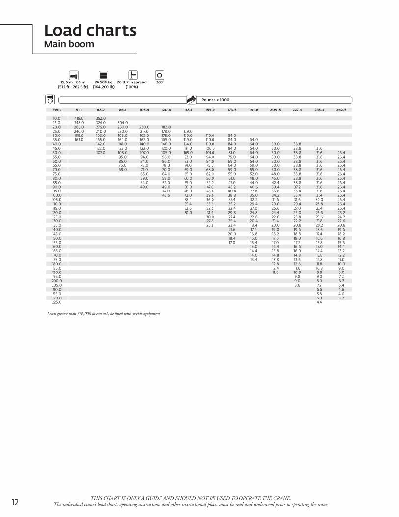
Load chartsMain boom
THIS CHART IS ONLY A GUIDE AND SHOULD NOT BE USED TO OPERATE THE CRANE. The individual crane’s load chart, operating instructions and other instructional plates must be read and understood prior to operating the crane
OutriggersCounterweight
Pounds x 1000Boom Extension
Feet 51.1 68.7 86.1 103.4 120.8 138.1 155.9 173.5 191.6 209.5 227.4 245.3 262.5
10.0 418.0 352.015.0 348.0 324.0 304.020.0 286.0 276.0 260.0 230.0 182.025.0 240.0 240.0 230.0 217.0 178.0 139.030.0 195.0 196.0 196.0 192.0 178.0 139.0 110.0 84.035.0 163.0 165.0 164.0 162.0 165.0 139.0 110.0 84.0 64.040.0 142.0 141.0 140.0 140.0 134.0 110.0 84.0 64.0 50.0 38.845.0 122.0 123.0 122.0 120.0 121.0 106.0 84.0 64.0 50.0 38.8 31.650.0 107.0 108.0 107.0 105.0 105.0 101.0 81.0 64.0 50.0 38.8 31.6 26.455.0 95.0 94.0 96.0 93.0 94.0 75.0 64.0 50.0 38.8 31.6 26.460.0 85.0 84.0 86.0 83.0 84.0 69.0 64.0 50.0 38.8 31.6 26.465.0 76.0 78.0 78.0 74.0 75.0 64.0 59.0 50.0 38.8 31.6 26.470.0 69.0 71.0 70.0 69.0 68.0 59.0 55.0 50.0 38.8 31.6 26.475.0 65.0 64.0 65.0 62.0 55.0 52.0 48.0 38.8 31.6 26.480.0 59.0 58.0 60.0 56.0 51.0 48.0 45.0 38.8 31.6 26.485.0 54.0 52.0 55.0 52.0 47.0 44.0 42.4 38.8 31.6 26.490.0 49.0 49.0 50.0 47.0 43.2 40.6 39.4 37.2 31.6 26.495.0 47.0 46.0 43.4 40.4 37.8 36.6 35.4 31.6 26.4
100.0 43.6 42.0 39.6 38.8 35.0 34.2 33.4 31.4 26.4105.0 38.4 36.0 37.4 32.2 31.6 31.6 30.0 26.4110.0 35.4 33.6 35.2 29.4 29.0 29.4 28.8 26.4115.0 32.6 32.6 32.4 27.0 26.6 27.0 27.4 26.4120.0 30.0 31.4 29.8 24.8 24.4 25.0 25.6 25.2125.0 30.0 27.4 22.6 22.6 23.8 23.6 24.2130.0 27.8 25.4 20.4 21.4 22.2 21.8 22.6135.0 25.8 23.4 18.4 20.0 20.8 20.2 20.8140.0 21.6 17.4 19.0 19.6 18.6 19.6145.0 20.0 16.8 18.2 18.8 17.4 18.2150.0 18.4 16.0 17.6 18.0 16.6 16.8155.0 17.0 15.4 17.0 17.2 15.8 15.6160.0 15.0 16.4 16.6 15.0 14.4165.0 14.4 15.8 16.0 14.4 13.2170.0 14.0 14.8 14.8 13.8 12.2175.0 13.4 13.8 13.6 12.8 11.0180.0 12.8 12.6 11.8 10.0185.0 12.4 11.6 10.8 9.0190.0 11.8 10.8 9.8 8.0195.0 9.8 9.0 7.2200.0 9.0 8.0 6.2205.0 8.6 7.2 5.4210.0 6.6 4.6215.0 5.8 4.0220.0 5.0 3.2225.0 4.4
15,6 m - 80 m 74 500 kg 26 ft 7 in spread 360˚(51.1 ft - 262.5 ft) (164,200 lb) (100%)
Loads greater than 376,000 lb can only be lifted with special equipment.
13Grove GMK6300L
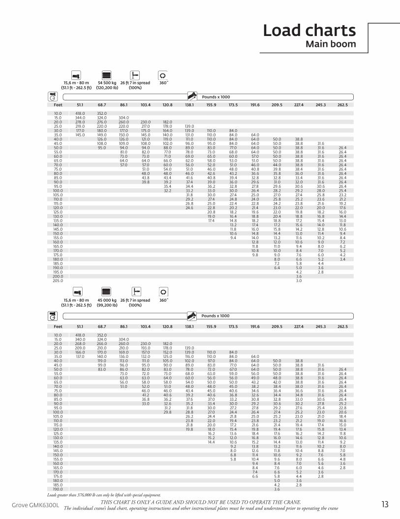
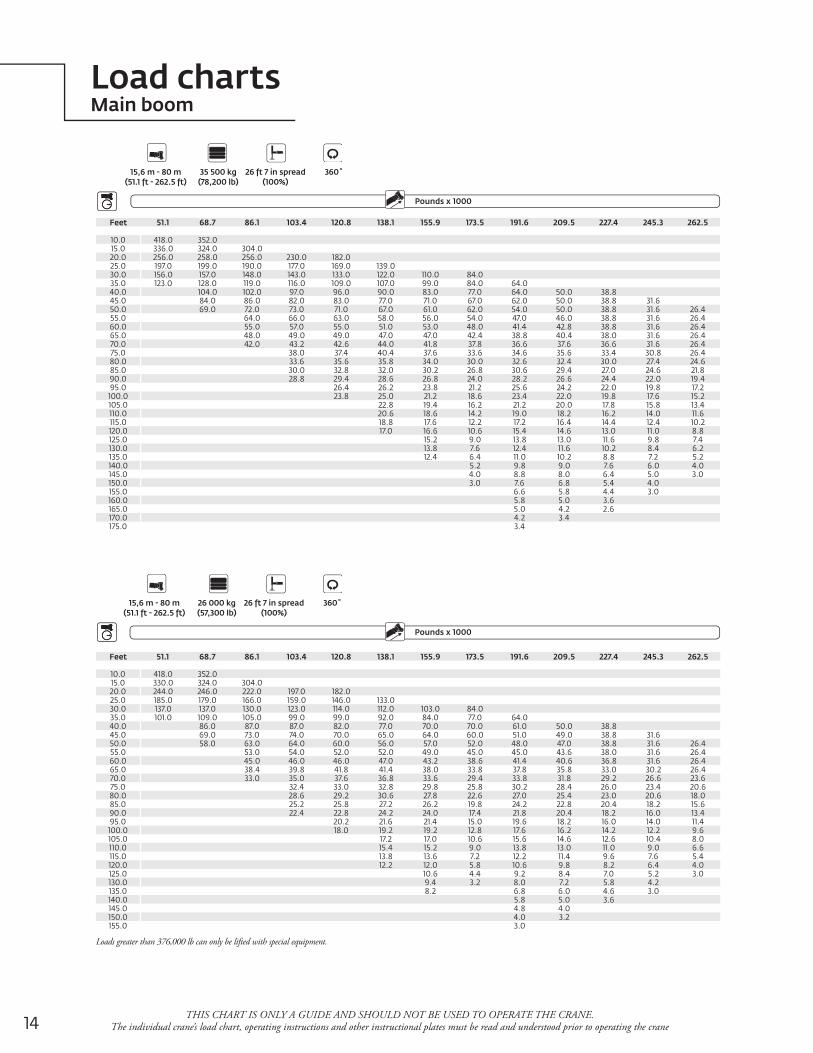
Load chartsMain boom
THIS CHART IS ONLY A GUIDE AND SHOULD NOT BE USED TO OPERATE THE CRANE. The individual crane’s load chart, operating instructions and other instructional plates must be read and understood prior to operating the crane
Feet 51.1 68.7 86.1 103.4 120.8 138.1 155.9 173.5 191.6 209.5 227.4 245.3 262.5
10.0 418.0 352.015.0 344.0 324.0 304.020.0 278.0 276.0 260.0 230.0 182.025.0 219.0 220.0 220.0 217.0 178.0 139.030.0 177.0 180.0 177.0 175.0 164.0 139.0 110.0 84.035.0 145.0 149.0 150.0 145.0 140.0 131.0 110.0 84.0 64.040.0 126.0 126.0 121.0 119.0 111.0 110.0 84.0 64.0 50.0 38.845.0 108.0 109.0 108.0 102.0 96.0 95.0 84.0 64.0 50.0 38.8 31.650.0 95.0 94.0 94.0 88.0 89.0 83.0 77.0 64.0 50.0 38.8 31.6 26.455.0 81.0 82.0 77.0 78.0 73.0 68.0 64.0 50.0 38.8 31.6 26.460.0 73.0 73.0 71.0 69.0 65.0 60.0 57.0 50.0 38.8 31.6 26.465.0 64.0 64.0 66.0 62.0 58.0 53.0 51.0 50.0 38.8 31.6 26.470.0 57.0 57.0 60.0 56.0 52.0 51.0 46.0 44.0 38.8 31.6 26.475.0 51.0 54.0 51.0 46.0 48.0 40.8 39.8 38.4 31.6 26.480.0 48.0 48.0 46.0 42.6 43.2 36.6 35.8 36.0 31.6 26.485.0 43.8 43.4 41.6 40.8 39.4 32.8 32.8 33.4 31.6 26.490.0 39.8 39.2 37.4 39.0 36.0 29.6 31.0 32.0 31.6 26.495.0 35.4 34.4 36.2 32.8 27.8 29.6 30.6 30.6 26.4
100.0 32.2 33.2 33.0 30.0 26.4 28.2 29.2 28.0 25.4105.0 31.8 30.0 27.4 25.0 27.0 27.4 25.8 23.2110.0 29.2 27.4 24.8 24.0 25.8 25.2 23.6 21.2115.0 26.8 25.0 22.4 22.8 24.2 23.8 21.6 19.2120.0 24.6 22.8 20.2 21.4 23.0 22.0 20.0 17.6125.0 20.8 18.2 19.6 22.0 19.8 18.2 16.0130.0 19.0 16.4 18.8 20.4 18.8 16.8 14.4135.0 17.4 14.8 18.2 18.8 17.2 15.4 13.0140.0 13.2 17.4 17.2 15.6 14.0 11.8145.0 11.8 16.0 15.8 14.2 12.8 10.6150.0 10.6 14.8 14.4 13.0 11.4 9.4155.0 9.4 14.0 13.2 11.6 10.2 8.4160.0 12.8 12.0 10.6 9.0 7.2165.0 11.8 11.0 9.4 8.0 6.2170.0 10.8 10.0 8.4 7.0 5.2175.0 9.8 9.0 7.6 6.0 4.2180.0 8.0 6.6 5.2 3.4185.0 7.2 5.8 4.4190.0 6.4 5.0 3.6195.0 4.2 2.8200.0 3.6205.0 3.0
OutriggersCounterweight
Pounds x 1000Boom Extension
15,6 m - 80 m 54 500 kg 26 ft 7 in spread 360˚ (51.1 ft - 262.5 ft) (120,200 lb) (100%)
Feet 51.1 68.7 86.1 103.4 120.8 138.1 155.9 173.5 191.6 209.5 227.4 245.3 262.5
10.0 418.0 352.015.0 340.0 324.0 304.020.0 268.0 266.0 260.0 230.0 182.025.0 209.0 210.0 210.0 193.0 178.0 139.030.0 166.0 170.0 169.0 157.0 152.0 139.0 110.0 84.035.0 137.0 140.0 136.0 132.0 125.0 116.0 110.0 84.0 64.040.0 119.0 113.0 111.0 105.0 102.0 97.0 84.0 64.0 50.0 38.845.0 99.0 96.0 95.0 90.0 89.0 83.0 77.0 64.0 50.0 38.8 31.650.0 83.0 86.0 82.0 83.0 78.0 72.0 67.0 64.0 50.0 38.8 31.6 26.455.0 73.0 72.0 73.0 68.0 63.0 59.0 56.0 50.0 38.8 31.6 26.460.0 63.0 63.0 64.0 60.0 56.0 56.0 49.0 48.0 38.8 31.6 26.465.0 56.0 58.0 58.0 54.0 50.0 50.0 43.2 42.0 38.8 31.6 26.470.0 51.0 52.0 51.0 48.0 48.0 45.0 38.2 38.4 38.0 31.6 26.475.0 46.0 46.0 43.4 45.0 40.6 34.6 36.4 36.6 31.6 26.480.0 41.2 40.6 39.2 40.6 36.8 32.6 34.4 34.8 31.6 26.485.0 36.8 36.2 37.6 37.0 33.2 30.8 32.8 33.0 30.6 26.490.0 33.0 32.6 35.2 33.4 30.0 29.2 30.6 30.2 27.8 25.295.0 31.2 31.8 30.0 27.2 27.8 29.2 27.6 25.4 22.8
100.0 29.8 28.8 27.0 24.4 26.4 27.4 25.2 23.0 20.6105.0 26.2 24.4 21.8 25.0 25.2 23.0 21.0 18.4110.0 23.8 22.0 19.4 23.8 23.2 21.2 19.0 16.6115.0 21.8 20.0 17.2 21.6 21.4 19.4 17.4 15.0120.0 19.8 18.0 15.4 19.8 19.4 17.6 15.8 13.4125.0 16.2 13.6 18.4 17.6 16.2 14.2 11.8130.0 15.2 12.0 16.8 16.0 14.6 12.8 10.6135.0 14.4 10.6 15.2 14.4 13.0 11.4 9.2140.0 9.2 13.8 13.2 11.6 10.2 8.0145.0 8.0 12.6 11.8 10.4 8.8 7.0150.0 6.8 11.4 10.6 9.2 7.6 5.8155.0 5.8 10.4 9.6 8.0 6.6 4.8160.0 9.4 8.4 7.0 5.6 3.6165.0 8.4 7.6 6.0 4.6 2.8170.0 7.4 6.6 5.2 3.6175.0 6.6 5.8 4.4 2.8180.0 5.0 3.6185.0 4.2 2.8190.0 3.6
OutriggersCounterweight
Pounds x 1000Boom Extension
15,6 m - 80 m 45 000 kg 26 ft 7 in spread 360˚ (51.1 ft - 262.5 ft) (99,200 lb) (100%)
Loads greater than 376,000 lb can only be lifted with special equipment.
14THIS CHART IS ONLY A GUIDE AND SHOULD NOT BE USED TO OPERATE THE CRANE.
The individual crane’s load chart, operating instructions and other instructional plates must be read and understood prior to operating the crane
Feet 51.1 68.7 86.1 103.4 120.8 138.1 155.9 173.5 191.6 209.5 227.4 245.3 262.5
10.0 418.0 352.015.0 336.0 324.0 304.020.0 256.0 258.0 256.0 230.0 182.025.0 197.0 199.0 190.0 177.0 169.0 139.030.0 156.0 157.0 148.0 143.0 133.0 122.0 110.0 84.035.0 123.0 128.0 119.0 116.0 109.0 107.0 99.0 84.0 64.040.0 104.0 102.0 97.0 96.0 90.0 83.0 77.0 64.0 50.0 38.845.0 84.0 86.0 82.0 83.0 77.0 71.0 67.0 62.0 50.0 38.8 31.650.0 69.0 72.0 73.0 71.0 67.0 61.0 62.0 54.0 50.0 38.8 31.6 26.455.0 64.0 66.0 63.0 58.0 56.0 54.0 47.0 46.0 38.8 31.6 26.460.0 55.0 57.0 55.0 51.0 53.0 48.0 41.4 42.8 38.8 31.6 26.465.0 48.0 49.0 49.0 47.0 47.0 42.4 38.8 40.4 38.0 31.6 26.470.0 42.0 43.2 42.6 44.0 41.8 37.8 36.6 37.6 36.6 31.6 26.475.0 38.0 37.4 40.4 37.6 33.6 34.6 35.6 33.4 30.8 26.480.0 33.6 35.6 35.8 34.0 30.0 32.6 32.4 30.0 27.4 24.685.0 30.0 32.8 32.0 30.2 26.8 30.6 29.4 27.0 24.6 21.890.0 28.8 29.4 28.6 26.8 24.0 28.2 26.6 24.4 22.0 19.495.0 26.4 26.2 23.8 21.2 25.6 24.2 22.0 19.8 17.2
100.0 23.8 25.0 21.2 18.6 23.4 22.0 19.8 17.6 15.2105.0 22.8 19.4 16.2 21.2 20.0 17.8 15.8 13.4110.0 20.6 18.6 14.2 19.0 18.2 16.2 14.0 11.6115.0 18.8 17.6 12.2 17.2 16.4 14.4 12.4 10.2120.0 17.0 16.6 10.6 15.4 14.6 13.0 11.0 8.8125.0 15.2 9.0 13.8 13.0 11.6 9.8 7.4130.0 13.8 7.6 12.4 11.6 10.2 8.4 6.2135.0 12.4 6.4 11.0 10.2 8.8 7.2 5.2140.0 5.2 9.8 9.0 7.6 6.0 4.0145.0 4.0 8.8 8.0 6.4 5.0 3.0150.0 3.0 7.6 6.8 5.4 4.0155.0 6.6 5.8 4.4 3.0160.0 5.8 5.0 3.6165.0 5.0 4.2 2.6170.0 4.2 3.4175.0 3.4
OutriggersCounterweight
Pounds x 1000Boom Extension
15,6 m - 80 m 35 500 kg 26 ft 7 in spread 360˚ (51.1 ft - 262.5 ft) (78,200 lb) (100%)
Feet 51.1 68.7 86.1 103.4 120.8 138.1 155.9 173.5 191.6 209.5 227.4 245.3 262.5
10.0 418.0 352.015.0 330.0 324.0 304.020.0 244.0 246.0 222.0 197.0 182.025.0 185.0 179.0 166.0 159.0 146.0 133.030.0 137.0 137.0 130.0 123.0 114.0 112.0 103.0 84.035.0 101.0 109.0 105.0 99.0 99.0 92.0 84.0 77.0 64.040.0 86.0 87.0 87.0 82.0 77.0 70.0 70.0 61.0 50.0 38.845.0 69.0 73.0 74.0 70.0 65.0 64.0 60.0 51.0 49.0 38.8 31.650.0 58.0 63.0 64.0 60.0 56.0 57.0 52.0 48.0 47.0 38.8 31.6 26.455.0 53.0 54.0 52.0 52.0 49.0 45.0 45.0 43.6 38.0 31.6 26.460.0 45.0 46.0 46.0 47.0 43.2 38.6 41.4 40.6 36.8 31.6 26.465.0 38.4 39.8 41.8 41.4 38.0 33.8 37.8 35.8 33.0 30.2 26.470.0 33.0 35.0 37.6 36.8 33.6 29.4 33.8 31.8 29.2 26.6 23.675.0 32.4 33.0 32.8 29.8 25.8 30.2 28.4 26.0 23.4 20.680.0 28.6 29.2 30.6 27.8 22.6 27.0 25.4 23.0 20.6 18.085.0 25.2 25.8 27.2 26.2 19.8 24.2 22.8 20.4 18.2 15.690.0 22.4 22.8 24.2 24.0 17.4 21.8 20.4 18.2 16.0 13.495.0 20.2 21.6 21.4 15.0 19.6 18.2 16.0 14.0 11.4
100.0 18.0 19.2 19.2 12.8 17.6 16.2 14.2 12.2 9.6105.0 17.2 17.0 10.6 15.6 14.6 12.6 10.4 8.0110.0 15.4 15.2 9.0 13.8 13.0 11.0 9.0 6.6115.0 13.8 13.6 7.2 12.2 11.4 9.6 7.6 5.4120.0 12.2 12.0 5.8 10.6 9.8 8.2 6.4 4.0125.0 10.6 4.4 9.2 8.4 7.0 5.2 3.0130.0 9.4 3.2 8.0 7.2 5.8 4.2135.0 8.2 6.8 6.0 4.6 3.0140.0 5.8 5.0 3.6145.0 4.8 4.0150.0 4.0 3.2155.0 3.0
OutriggersCounterweight
Pounds x 1000Boom Extension
15,6 m - 80 m 26 000 kg 26 ft 7 in spread 360˚(51.1 ft - 262.5 ft) (57,300 lb) (100%)
Load chartsMain boom
Loads greater than 376,000 lb can only be lifted with special equipment.
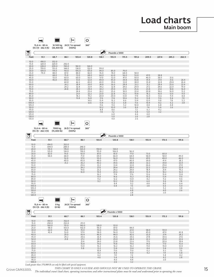
15Grove GMK6300L THIS CHART IS ONLY A GUIDE AND SHOULD NOT BE USED TO OPERATE THE CRANE. The individual crane’s load chart, operating instructions and other instructional plates must be read and understood prior to operating the crane
Feet 51.1 68.7 86.1 103.4 120.8 138.1 155.9 173.5 191.6 209.5 227.4 245.3 262.5
10.0 418.0 352.015.0 320.0 320.0 292.020.0 228.0 209.0 190.0 182.0 164.025.0 159.0 153.0 144.0 134.0 122.0 119.030.0 109.0 114.0 110.0 105.0 101.0 94.0 85.0 79.035.0 79.0 88.0 87.0 88.0 82.0 76.0 74.0 68.0 58.040.0 68.0 75.0 72.0 68.0 64.0 63.0 56.0 53.0 47.0 38.845.0 55.0 60.0 60.0 56.0 57.0 53.0 47.0 50.0 46.0 38.0 31.650.0 45.0 49.0 51.0 52.0 49.0 45.0 39.8 43.8 41.4 37.4 31.6 26.455.0 40.8 42.2 45.0 43.0 39.6 33.8 38.0 35.8 32.8 29.8 26.460.0 34.2 38.4 39.0 38.8 36.6 28.8 33.2 31.2 28.4 25.6 22.465.0 29.2 32.8 33.4 34.2 32.8 24.6 29.0 27.2 24.6 22.0 19.070.0 24.8 28.2 29.4 30.2 29.0 21.0 25.6 23.8 21.4 18.8 16.075.0 24.4 25.4 26.2 25.6 18.0 22.4 20.8 18.6 16.0 13.280.0 21.0 22.2 23.0 22.8 15.2 19.8 18.2 16.0 13.6 11.085.0 18.2 19.2 20.0 20.0 12.8 17.4 16.0 13.6 11.4 8.890.0 15.8 16.8 17.6 17.4 10.6 15.2 13.8 11.6 9.4 7.095.0 14.6 15.4 15.2 8.6 13.4 12.0 9.8 7.8 5.2
100.0 12.6 13.4 13.2 6.8 11.6 10.4 8.2 6.2 3.8105.0 11.6 11.6 5.2 10.0 8.8 6.8 4.8110.0 10.2 10.0 3.6 8.6 7.4 5.4 3.6115.0 8.8 8.6 7.2 6.2 4.2120.0 7.4 7.2 5.8 5.0 3.2125.0 6.0 4.6 4.0130.0 5.0 3.6 2.8135.0 4.0 2.6
OutriggersCounterweight
Pounds x 1000Boom Extension
15,6 m - 80 m 16 500 kg 26 ft 7 in spread 360˚(51.1 ft - 262.5 ft) (36,400 lb) (100%)
Feet 51.1 68.7 86.1 103.4 120.8 138.1 155.9 173.5 191.6
10.0 414.0 352.015.0 304.0 288.0 248.020.0 191.0 178.0 165.0 150.0 134.025.0 125.0 124.0 118.0 115.0 106.0 96.030.0 82.0 91.0 92.0 87.0 81.0 77.0 73.0 60.035.0 58.0 68.0 71.0 69.0 66.0 64.0 58.0 58.0 49.040.0 52.0 57.0 55.0 56.0 55.0 47.0 49.0 46.045.0 40.0 45.0 48.0 47.0 46.0 39.0 41.4 38.250.0 31.2 36.2 40.2 39.6 38.8 32.2 34.8 32.055.0 29.6 33.2 33.4 32.8 26.6 29.4 27.060.0 24.2 27.6 28.4 28.0 22.2 25.0 22.865.0 19.6 23.2 24.2 24.0 18.4 21.4 19.270.0 16.0 19.4 20.6 20.6 15.4 18.2 16.475.0 16.2 17.4 17.6 12.6 15.6 13.880.0 13.4 14.6 15.2 10.2 13.4 11.685.0 11.2 12.2 13.0 8.2 11.2 9.690.0 9.2 10.2 11.0 6.4 9.6 7.895.0 8.4 9.2 4.8 8.0 6.4
100.0 6.8 7.6 3.4 6.6 5.0105.0 6.2 5.2 3.8110.0 4.8 4.0 2.6115.0 3.8 3.0120.0 2.8
OutriggersCounterweight
Pounds x 1000Boom Extension
15,6 m - 80 m 7000 kg 26 ft 7 in spread 360˚ (51.1 ft - 262.5 ft) (15,400 lb) (100%)
Feet 51.1 68.7 86.1 103.4 120.8 138.1 155.9 173.3 191.6
10.0 410.0 352.015.0 290.0 252.0 211.020.0 160.0 151.0 140.0 128.0 121.025.0 98.0 103.0 102.0 96.0 87.0 84.030.0 62.0 74.0 74.0 70.0 70.0 67.0 58.0 59.035.0 42.4 53.0 57.0 58.0 56.0 53.0 45.0 47.0 42.840.0 39.0 43.4 46.0 44.0 42.6 35.0 37.4 34.245.0 29.2 34.6 36.4 35.6 34.6 27.8 30.6 27.650.0 21.8 27.2 29.4 29.0 28.4 22.2 25.0 22.655.0 21.4 24.0 23.8 23.6 17.6 20.6 18.460.0 16.8 19.6 19.8 19.6 14.0 17.0 15.065.0 13.0 16.2 16.2 16.2 11.0 14.0 12.070.0 9.8 13.2 13.4 13.4 8.4 11.4 9.675.0 10.4 11.0 11.0 6.2 9.2 7.680.0 8.2 8.8 9.0 4.2 7.4 5.885.0 6.2 7.0 7.2 5.8 4.290.0 4.6 5.4 5.8 4.2 2.895.0 4.0 4.4 3.0
100.0 2.6 3.2
OutriggersCounterweight
Pounds x 1000Boom Extension
15,6 m - 80 m 0 kg 26 ft 7 in spread 360˚(51.1 ft - 262.5 ft) (0 lb) (100%)
Load chartsMain boom
Loads greater than 376,000 lb can only be lifted with special equipment.
16
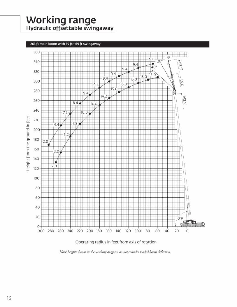
Working rangeHydraulic offsettable swingaway
263 ft main boom with 39 ft - 69 ft swingaway
Hook heights shown in the working diagram do not consider loaded boom deflection.
Hei
ght
from
the
gro
und
in fe
et
Operating radius in feet from axis of rotation
+ 68.9'+ 39.4'
262.5'
40°
5°
83°
20°
20
0
40
60
80
100
120
140
160
180
200
220
240
260
280
300
320
340
360
300 280 260 240 220 200 180 160 140 120 100 80 60 40 20 0
15.015.015.0
15.015.0
14.2
12.2
10.0
7.8
5.2
9.49.4
9.4
9.4
8.4
7.2
4.4
9.4
2.0
2.0
3.0
9.4
9.4

17Grove GMK6300LTHIS CHART IS ONLY A GUIDE AND SHOULD NOT BE USED TO OPERATE THE CRANE.
The individual crane’s load chart, operating instructions and other instructional plates must be read and understood prior to operating the crane
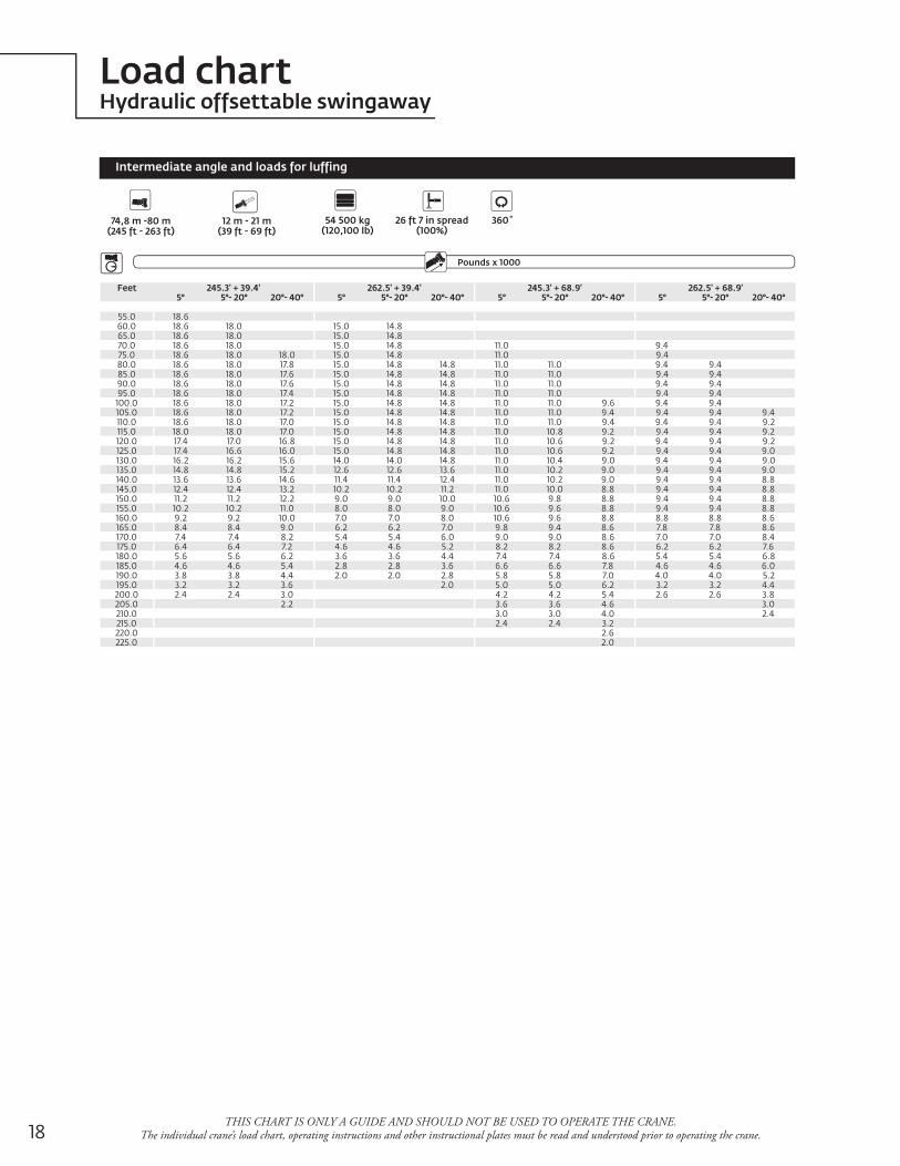
Load chartsHydraulic offsettable swingaway
Feet 245.3' + 39.4' 262.5' + 39.4' 245.3' + 68.9' 262.5' + 68.9'5° 5°- 20° 20°- 40° 5° 5°- 20° 20°- 40° 5° 5°- 20° 20°- 40° 5° 5°- 20° 20°- 40°
55.0 18.660.0 18.6 18.0 15.0 14.865.0 18.6 18.0 15.0 14.870.0 18.6 18.0 15.0 14.8 11.0 9.475.0 18.6 18.0 18.0 15.0 14.8 11.0 9.480.0 18.6 18.0 17.8 15.0 14.8 14.8 11.0 11.0 9.4 9.485.0 18.6 18.0 17.6 15.0 14.8 14.8 11.0 11.0 9.4 9.490.0 18.6 18.0 17.6 15.0 14.8 14.8 11.0 11.0 9.4 9.495.0 18.6 18.0 17.4 15.0 14.8 14.8 11.0 11.0 9.4 9.4
100.0 18.6 18.0 17.2 15.0 14.8 14.8 11.0 11.0 9.6 9.4 9.4105.0 18.6 18.0 17.2 15.0 14.8 14.8 11.0 11.0 9.4 9.4 9.4 9.4110.0 18.6 18.0 17.0 15.0 14.8 14.8 11.0 11.0 9.4 9.4 9.4 9.2115.0 18.6 18.0 17.0 15.0 14.8 14.8 11.0 10.8 9.2 9.4 9.4 9.2120.0 18.6 18.0 16.8 15.0 14.8 14.8 11.0 10.6 9.2 9.4 9.4 9.2125.0 18.6 18.0 16.8 15.0 14.8 14.8 11.0 10.6 9.2 9.4 9.4 9.0130.0 18.6 18.0 16.6 15.0 14.8 14.8 11.0 10.4 9.0 9.4 9.4 9.0135.0 18.4 18.0 16.6 15.0 14.8 14.8 11.0 10.2 9.0 9.4 9.4 9.0140.0 17.8 17.6 16.4 15.0 14.8 14.8 11.0 10.2 9.0 9.4 9.4 8.8145.0 17.0 17.0 16.4 15.0 14.8 14.8 11.0 10.0 8.8 9.4 9.4 8.8150.0 16.2 16.2 16.2 15.0 14.8 14.6 11.0 9.8 8.8 9.4 9.4 8.8155.0 15.4 15.4 15.6 14.6 14.6 14.4 11.0 9.8 8.8 9.4 9.4 8.8160.0 14.6 14.6 15.0 14.2 14.2 14.2 11.0 9.6 8.8 9.4 9.4 8.6165.0 14.0 14.0 14.4 13.8 13.6 13.6 10.8 9.6 8.6 9.4 9.4 8.6170.0 13.4 13.4 13.6 13.2 13.2 13.2 10.6 9.4 8.6 9.4 9.4 8.6175.0 12.6 12.6 13.0 12.4 12.4 12.8 10.4 9.4 8.6 9.4 9.2 8.6180.0 11.8 11.8 12.4 12.0 12.0 12.2 10.4 9.2 8.6 9.4 9.2 8.6185.0 11.0 11.0 11.6 11.4 11.4 11.8 10.2 9.2 8.6 9.4 9.2 8.4190.0 10.4 10.4 11.0 10.8 10.8 11.2 10.0 9.0 8.6 9.4 9.0 8.4195.0 9.6 9.6 10.2 10.2 10.2 10.6 10.0 9.0 8.4 9.4 9.0 8.4200.0 9.0 9.0 9.6 9.6 9.6 10.0 9.6 9.0 8.4 9.4 8.8 8.4205.0 8.6 8.6 8.8 9.0 9.0 9.6 9.4 8.8 8.4 9.2 8.8 8.4210.0 8.2 8.2 8.4 8.4 8.4 9.0 9.0 8.8 8.4 8.8 8.6 8.4215.0 7.8 7.8 8.0 8.0 8.0 8.4 8.4 8.4 8.4 8.6 8.6 8.4220.0 7.4 7.4 7.4 7.4 7.8 7.8 7.8 8.4 8.2 8.2 8.4225.0 7.0 7.0 6.8 6.8 7.2 7.4 7.4 8.2 7.8 7.8 8.0230.0 6.6 6.6 6.4 6.4 6.8 6.8 7.6 7.4 7.4 7.8235.0 6.2 6.2 5.8 5.8 6.4 6.4 7.0 6.8 6.8 7.6240.0 5.8 5.8 5.2 5.2 6.0 6.0 6.6 6.4 6.4 7.2245.0 5.6 5.6 4.6 4.6 5.8 5.8 6.0 6.0 6.6250.0 5.2 5.2 4.0 4.0 5.4 5.4 5.6 5.6 6.2255.0 4.8 4.8 3.4 3.4 5.2 5.2 5.0 5.0 5.6260.0 4.4 3.0 3.0 4.8 4.8 4.4 4.4265.0 2.4 2.4 4.6 4.6 4.0 4.0270.0 2.0 2.0 4.2 4.2 3.4 3.4275.0 4.0 4.0 3.0 3.0280.0 3.8 3.8 2.4 2.4285.0 3.4 3.4 2.0 2.0
Pounds x 1000Boom Extension
Outriggers
74,8 m -80 m (245 ft - 263 ft)
12 m - 21 m(39 ft - 69 ft)
26 ft 7 in spread(100%)
360˚92 500 kg(203,900 lb)
Counterweight
Intermediate angle and loads for luffing
18
Load chartHydraulic offsettable swingaway
THIS CHART IS ONLY A GUIDE AND SHOULD NOT BE USED TO OPERATE THE CRANE. The individual crane’s load chart, operating instructions and other instructional plates must be read and understood prior to operating the crane.
Feet 245.3' + 39.4' 262.5' + 39.4' 245.3' + 68.9' 262.5' + 68.9'5° 5°- 20° 20°- 40° 5° 5°- 20° 20°- 40° 5° 5°- 20° 20°- 40° 5° 5°- 20° 20°- 40°
55.0 18.660.0 18.6 18.0 15.0 14.865.0 18.6 18.0 15.0 14.870.0 18.6 18.0 15.0 14.8 11.0 9.475.0 18.6 18.0 18.0 15.0 14.8 11.0 9.480.0 18.6 18.0 17.8 15.0 14.8 14.8 11.0 11.0 9.4 9.485.0 18.6 18.0 17.6 15.0 14.8 14.8 11.0 11.0 9.4 9.490.0 18.6 18.0 17.6 15.0 14.8 14.8 11.0 11.0 9.4 9.495.0 18.6 18.0 17.4 15.0 14.8 14.8 11.0 11.0 9.4 9.4
100.0 18.6 18.0 17.2 15.0 14.8 14.8 11.0 11.0 9.6 9.4 9.4105.0 18.6 18.0 17.2 15.0 14.8 14.8 11.0 11.0 9.4 9.4 9.4 9.4110.0 18.6 18.0 17.0 15.0 14.8 14.8 11.0 11.0 9.4 9.4 9.4 9.2115.0 18.0 18.0 17.0 15.0 14.8 14.8 11.0 10.8 9.2 9.4 9.4 9.2120.0 17.4 17.0 16.8 15.0 14.8 14.8 11.0 10.6 9.2 9.4 9.4 9.2125.0 17.4 16.6 16.0 15.0 14.8 14.8 11.0 10.6 9.2 9.4 9.4 9.0130.0 16.2 16.2 15.6 14.0 14.0 14.8 11.0 10.4 9.0 9.4 9.4 9.0135.0 14.8 14.8 15.2 12.6 12.6 13.6 11.0 10.2 9.0 9.4 9.4 9.0140.0 13.6 13.6 14.6 11.4 11.4 12.4 11.0 10.2 9.0 9.4 9.4 8.8145.0 12.4 12.4 13.2 10.2 10.2 11.2 11.0 10.0 8.8 9.4 9.4 8.8150.0 11.2 11.2 12.2 9.0 9.0 10.0 10.6 9.8 8.8 9.4 9.4 8.8155.0 10.2 10.2 11.0 8.0 8.0 9.0 10.6 9.6 8.8 9.4 9.4 8.8160.0 9.2 9.2 10.0 7.0 7.0 8.0 10.6 9.6 8.8 8.8 8.8 8.6165.0 8.4 8.4 9.0 6.2 6.2 7.0 9.8 9.4 8.6 7.8 7.8 8.6170.0 7.4 7.4 8.2 5.4 5.4 6.0 9.0 9.0 8.6 7.0 7.0 8.4175.0 6.4 6.4 7.2 4.6 4.6 5.2 8.2 8.2 8.6 6.2 6.2 7.6180.0 5.6 5.6 6.2 3.6 3.6 4.4 7.4 7.4 8.6 5.4 5.4 6.8185.0 4.6 4.6 5.4 2.8 2.8 3.6 6.6 6.6 7.8 4.6 4.6 6.0190.0 3.8 3.8 4.4 2.0 2.0 2.8 5.8 5.8 7.0 4.0 4.0 5.2195.0 3.2 3.2 3.6 2.0 5.0 5.0 6.2 3.2 3.2 4.4200.0 2.4 2.4 3.0 4.2 4.2 5.4 2.6 2.6 3.8205.0 2.2 3.6 3.6 4.6 3.0210.0 3.0 3.0 4.0 2.4215.0 2.4 2.4 3.2220.0 2.6225.0 2.0
Pounds x 1000Boom Extension
Outriggers
26 ft 7 in spread(100%)
360˚54 500 kg(120,100 lb)
Counterweight
Intermediate angle and loads for luffing
74,8 m -80 m (245 ft - 263 ft)
12 m - 21 m(39 ft - 69 ft)
Grove GMK6300L 19
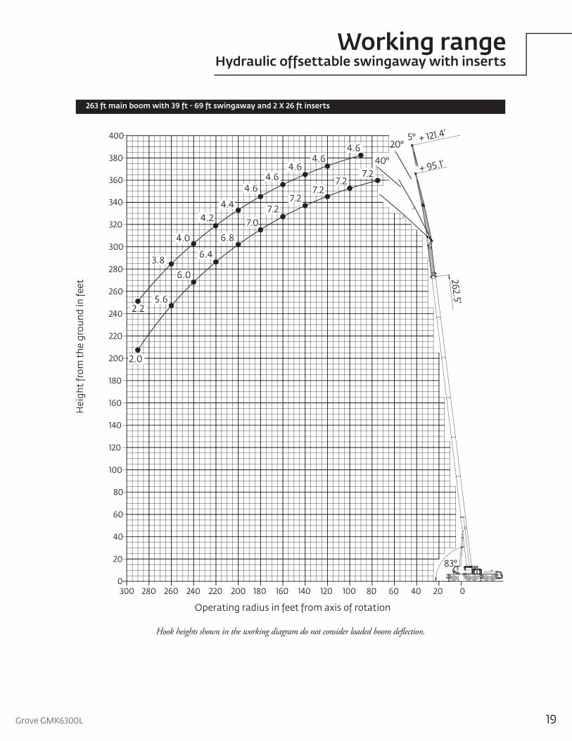
Working rangeHydraulic offsettable swingaway with inserts
263 ft main boom with 39 ft - 69 ft swingaway and 2 X 26 ft inserts
Hook heights shown in the working diagram do not consider loaded boom deflection.
Hei
ght
from
the
gro
und
in fe
et
Operating radius in feet from axis of rotation
260 240 220 200 180 160 140 120 100 80 60 40 20 0280300
360
380
400
20
0
40
60
80
100
120
140
160
180
200
220
240
260
280
300
320
340
83°
262.5'
+ 95.1'
+ 121.4'5°20°
40°4.6
4.44.2
7.2
4.6
7.27.2
7.27.2
7.0
6.8
4.6
4.0
3.8
2.2
6.4
6.0
5.6
4.64.6
2.0
20
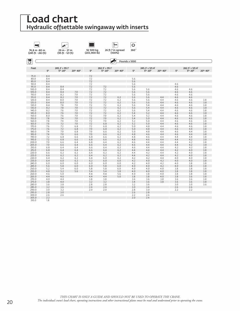
Load chartHydraulic offsettable swingaway with inserts
THIS CHART IS ONLY A GUIDE AND SHOULD NOT BE USED TO OPERATE THE CRANE. The individual crane’s load chart, operating instructions and other instructional plates must be read and understood prior to operating the crane.
Feet 245.3' + 95.1' 262.5' + 95.1' 245.3' + 121.4' 262.5' + 121.4'5° 5°- 20° 20°- 40° 5° 5°- 20° 20°- 40° 5° 5°- 20° 20°- 40° 5° 5°- 20° 20°- 40°
75.0 8.4 7.280.0 8.4 7.2 5.685.0 8.4 7.2 5.690.0 8.4 7.2 5.6 4.695.0 8.4 8.4 7.2 7.2 5.6 4.6
100.0 8.4 8.4 7.2 7.2 5.6 5.6 4.6 4.6105.0 8.4 8.4 7.0 7.2 7.2 5.6 5.6 4.6 4.6110.0 8.4 8.2 7.0 7.2 7.2 5.6 5.6 4.6 4.6115.0 8.4 8.2 7.0 7.2 7.2 6.2 5.6 5.6 4.4 4.6 4.6120.0 8.4 8.0 7.0 7.2 7.2 6.2 5.6 5.6 4.4 4.6 4.6 3.8125.0 8.4 8.0 7.0 7.2 7.2 6.2 5.6 5.6 4.4 4.6 4.6 3.8130.0 8.4 7.8 7.0 7.2 7.2 6.2 5.6 5.4 4.4 4.6 4.6 3.8135.0 8.2 7.8 7.0 7.2 7.2 6.2 5.6 5.4 4.4 4.6 4.6 3.8140.0 8.2 7.6 7.0 7.2 7.2 6.2 5.6 5.4 4.4 4.6 4.6 3.8145.0 8.0 7.6 7.0 7.2 7.2 6.2 5.4 5.2 4.4 4.6 4.6 3.8150.0 8.0 7.6 7.0 7.2 7.0 6.2 5.4 5.2 4.4 4.6 4.6 3.8155.0 7.8 7.4 7.0 7.2 7.0 6.2 5.4 5.0 4.4 4.6 4.6 3.8160.0 7.8 7.4 7.0 7.2 7.0 6.2 5.2 5.0 4.4 4.6 4.6 3.8165.0 7.6 7.2 7.0 7.2 6.8 6.2 5.2 5.0 4.4 4.6 4.6 3.8170.0 7.6 7.2 6.8 7.2 6.8 6.2 5.0 4.8 4.4 4.6 4.6 3.8175.0 7.6 7.2 6.8 7.0 6.8 6.2 5.0 4.8 4.4 4.6 4.4 3.8180.0 7.4 7.0 6.8 7.0 6.6 6.2 5.0 4.8 4.4 4.6 4.4 3.8185.0 7.4 7.0 6.6 7.0 6.6 6.2 4.8 4.6 4.4 4.6 4.4 3.8190.0 7.2 6.8 6.6 6.8 6.6 6.2 4.8 4.6 4.4 4.4 4.4 3.8195.0 7.2 6.8 6.6 6.8 6.6 6.2 4.8 4.6 4.4 4.4 4.2 3.8200.0 7.0 6.6 6.4 6.8 6.4 6.2 4.6 4.4 4.4 4.4 4.2 3.8205.0 7.0 6.6 6.4 6.6 6.4 6.2 4.6 4.4 4.4 4.4 4.2 3.8210.0 6.8 6.4 6.4 6.6 6.4 6.2 4.6 4.4 4.4 4.2 4.2 3.8215.0 6.8 6.4 6.4 6.6 6.4 6.2 4.4 4.4 4.4 4.2 4.0 3.8220.0 6.6 6.2 6.2 6.4 6.2 6.2 4.4 4.2 4.4 4.2 4.0 3.8225.0 6.6 6.2 6.2 6.4 6.2 6.2 4.4 4.2 4.4 4.2 4.0 3.8230.0 6.4 6.2 6.2 6.4 6.0 6.2 4.2 4.2 4.4 4.0 4.0 3.8235.0 6.4 6.0 6.2 6.2 6.0 6.0 4.2 4.0 4.2 4.0 4.0 3.8240.0 6.0 6.0 6.0 6.0 6.0 6.0 4.2 4.0 4.2 4.0 3.8 3.8245.0 5.6 5.8 6.0 6.0 5.8 6.0 4.0 4.0 4.2 4.0 3.8 3.8250.0 5.2 5.4 6.0 5.8 5.8 6.0 4.0 4.0 4.0 3.8 3.8 3.8255.0 4.8 5.2 5.6 5.4 5.4 5.8 4.0 4.0 4.0 3.8 3.8 3.8260.0 4.6 5.0 4.8 4.8 5.6 4.0 3.8 4.0 3.8 3.8 3.8265.0 4.4 4.6 4.4 4.4 5.0 3.8 3.8 4.0 3.8 3.6 3.8270.0 4.0 4.4 3.8 3.8 3.6 3.6 3.8 3.6 3.6 3.8275.0 3.8 4.0 3.2 3.2 3.4 3.6 3.8 3.6 3.6 3.8280.0 3.6 3.8 2.8 2.8 3.2 3.6 3.0 3.0 3.6285.0 3.2 3.6 2.4 2.4 3.0 3.4 2.6 2.6290.0 3.0 3.2 2.0 2.0 2.8 3.0 2.2 2.2295.0 2.8 3.0 2.6 2.8300.0 2.6 2.6 2.2 2.6305.0 2.2 2.0 2.4310.0 1.8
Pounds x 1000Boom Extension
Outriggers
26 ft 7 in spread(100%)
360˚92 500 kg(203,900 lb)
Counterweight
74,8 m -80 m (245 ft - 263 ft)
29 m - 37 m(95 ft - 121 ft)
Grove GMK6300L 21THIS CHART IS ONLY A GUIDE AND SHOULD NOT BE USED TO OPERATE THE CRANE.
The individual crane’s load chart, operating instructions and other instructional plates must be read and understood prior to operating the crane.
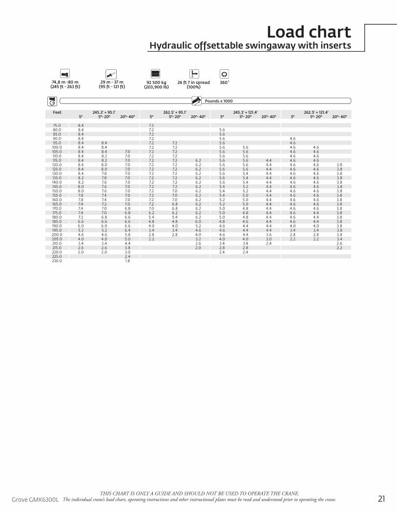
Load chartHydraulic offsettable swingaway with inserts
Feet 245.3' + 95.1' 262.5' + 95.1' 245.3' + 121.4' 262.5' + 121.4'5° 5°- 20° 20°- 40° 5° 5°- 20° 20°- 40° 5° 5°- 20° 20°- 40° 5° 5°- 20° 20°- 40°
75.0 8.4 7.280.0 8.4 7.2 5.685.0 8.4 7.2 5.690.0 8.4 7.2 5.6 4.695.0 8.4 8.4 7.2 7.2 5.6 4.6
100.0 8.4 8.4 7.2 7.2 5.6 5.6 4.6 4.6105.0 8.4 8.4 7.0 7.2 7.2 5.6 5.6 4.6 4.6110.0 8.4 8.2 7.0 7.2 7.2 5.6 5.6 4.6 4.6115.0 8.4 8.2 7.0 7.2 7.2 6.2 5.6 5.6 4.4 4.6 4.6120.0 8.4 8.0 7.0 7.2 7.2 6.2 5.6 5.6 4.4 4.6 4.6 3.8125.0 8.4 8.0 7.0 7.2 7.2 6.2 5.6 5.6 4.4 4.6 4.6 3.8130.0 8.4 7.8 7.0 7.2 7.2 6.2 5.6 5.4 4.4 4.6 4.6 3.8135.0 8.2 7.8 7.0 7.2 7.2 6.2 5.6 5.4 4.4 4.6 4.6 3.8140.0 8.2 7.6 7.0 7.2 7.2 6.2 5.6 5.4 4.4 4.6 4.6 3.8145.0 8.0 7.6 7.0 7.2 7.2 6.2 5.4 5.2 4.4 4.6 4.6 3.8150.0 8.0 7.6 7.0 7.2 7.0 6.2 5.4 5.2 4.4 4.6 4.6 3.8155.0 7.8 7.4 7.0 7.2 7.0 6.2 5.4 5.0 4.4 4.6 4.6 3.8160.0 7.8 7.4 7.0 7.2 7.0 6.2 5.2 5.0 4.4 4.6 4.6 3.8165.0 7.4 7.2 7.0 7.2 6.8 6.2 5.2 5.0 4.4 4.6 4.6 3.8170.0 7.4 7.0 6.8 7.0 6.8 6.2 5.0 4.8 4.4 4.6 4.6 3.8175.0 7.4 7.0 6.8 6.2 6.2 6.2 5.0 4.8 4.4 4.6 4.4 3.8180.0 7.2 6.8 6.6 5.4 5.4 6.2 5.0 4.8 4.4 4.6 4.4 3.8185.0 6.6 6.6 6.6 4.8 4.8 6.0 4.8 4.6 4.4 4.6 4.4 3.8190.0 6.0 6.0 6.6 4.0 4.0 5.2 4.6 4.4 4.4 4.0 4.0 3.8195.0 5.2 5.2 6.4 3.4 3.4 4.6 4.6 4.4 4.4 3.4 3.4 3.8200.0 4.6 4.6 5.8 2.8 2.8 4.0 4.6 4.4 3.6 2.8 2.8 3.8205.0 4.0 4.0 5.0 2.2 3.2 4.0 4.0 3.0 2.2 2.2 3.4210.0 3.4 3.4 4.4 2.6 3.4 3.4 2.4 2.6215.0 2.6 2.6 3.8 2.0 2.8 2.8 2.2220.0 2.0 2.0 3.0 2.4 2.4225.0 2.4230.0 1.8
Pounds x 1000Boom Extension
Outriggers
26 ft 7 in spread(100%)
360˚92 500 kg(203,900 lb)
Counterweight
74,8 m -80 m (245 ft - 263 ft)
29 m - 37 m(95 ft - 121 ft)
22
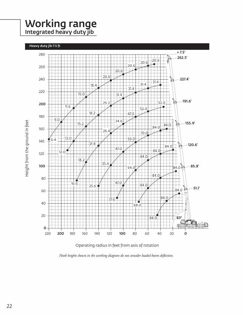
Working rangeIntegrated heavy duty jib
Heavy duty jib 7.5 ft
Hook heights shown in the working diagram do not consider loaded boom deflection.
Hei
ght
from
the
gro
und
in fe
et
Operating radius in feet from axis of rotation
+ 7.5'
220 200 180 160 140 120 100 80 60 40 20 0
51.1'
85.8'
120.6'
155.9'
191.6'
227.4'
262.5'
83°20
0
40
60
80
100
120
140
160
180
200
220
240
260
280
20.620.620.6
20.6
20.6
18.4
15.0
11.6
9.0
18.2
15.2
13.0
12.0
6.4
31.431.4
31.4
31.4
25.2 52.0
52.0
34.6
47.0
26.4
21.8
84.084.0
70.0
59.0
47.0
35.4
25.6
18.2
16.6
84.0
84.0
84.0
64.0
37.6
47.0
84.0
84.0
84.0
68.0
84.0
84.0
84.0
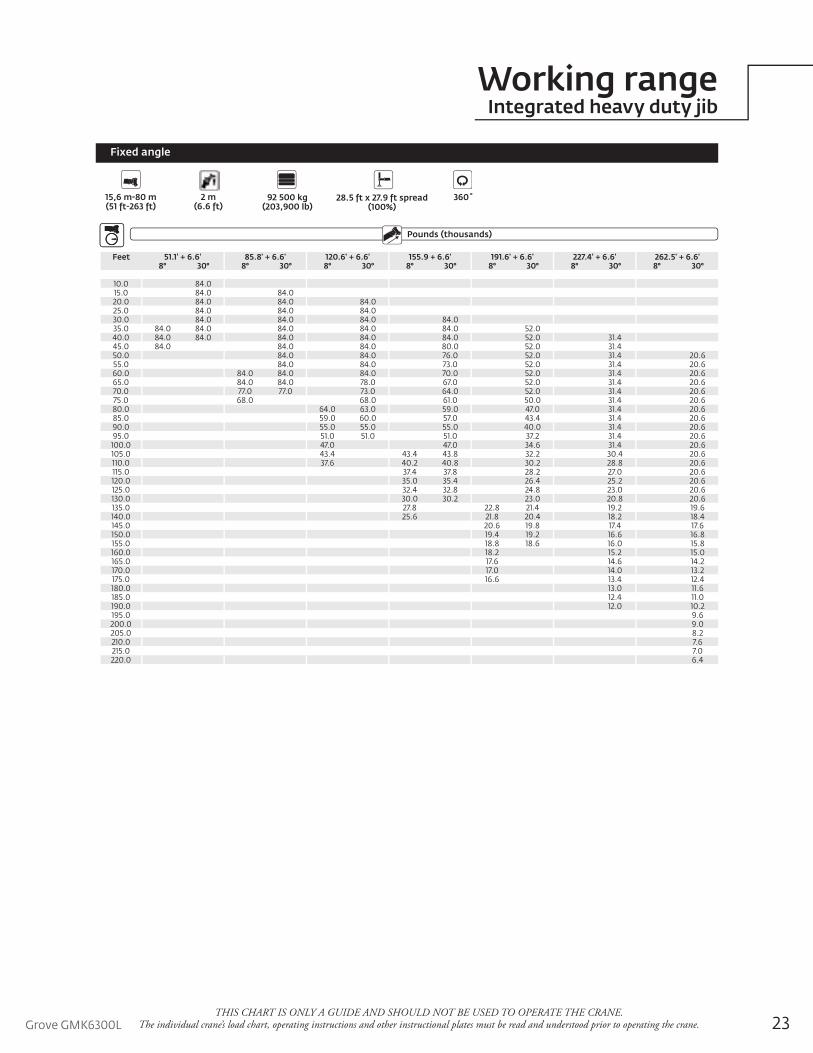
Working rangeIntegrated heavy duty jib
23Grove GMK6300L
Fixed angle
Boom ExtensionPounds (thousands)
Outriggers
15,6 m-80 m(51 ft-263 ft)
2 m(6.6 ft)
28.5 ft x 27.9 ft spread(100%)
360˚92 500 kg(203,900 lb)
Counterweight
Feet 51.1' + 6.6' 85.8' + 6.6' 120.6' + 6.6' 155.9 + 6.6' 191.6' + 6.6' 227.4' + 6.6' 262.5' + 6.6'8° 30° 8° 30° 8° 30° 8° 30° 8° 30° 8° 30° 8° 30°
10.0 84.015.0 84.0 84.020.0 84.0 84.0 84.025.0 84.0 84.0 84.030.0 84.0 84.0 84.0 84.035.0 84.0 84.0 84.0 84.0 84.0 52.040.0 84.0 84.0 84.0 84.0 84.0 52.0 31.445.0 84.0 84.0 84.0 80.0 52.0 31.450.0 84.0 84.0 76.0 52.0 31.4 20.655.0 84.0 84.0 73.0 52.0 31.4 20.660.0 84.0 84.0 84.0 70.0 52.0 31.4 20.665.0 84.0 84.0 78.0 67.0 52.0 31.4 20.670.0 77.0 77.0 73.0 64.0 52.0 31.4 20.675.0 68.0 68.0 61.0 50.0 31.4 20.680.0 64.0 63.0 59.0 47.0 31.4 20.685.0 59.0 60.0 57.0 43.4 31.4 20.690.0 55.0 55.0 55.0 40.0 31.4 20.695.0 51.0 51.0 51.0 37.2 31.4 20.6
100.0 47.0 47.0 34.6 31.4 20.6105.0 43.4 43.4 43.8 32.2 30.4 20.6110.0 37.6 40.2 40.8 30.2 28.8 20.6115.0 37.4 37.8 28.2 27.0 20.6120.0 35.0 35.4 26.4 25.2 20.6125.0 32.4 32.8 24.8 23.0 20.6130.0 30.0 30.2 23.0 20.8 20.6135.0 27.8 22.8 21.4 19.2 19.6140.0 25.6 21.8 20.4 18.2 18.4145.0 20.6 19.8 17.4 17.6150.0 19.4 19.2 16.6 16.8155.0 18.8 18.6 16.0 15.8160.0 18.2 15.2 15.0165.0 17.6 14.6 14.2170.0 17.0 14.0 13.2175.0 16.6 13.4 12.4180.0 13.0 11.6185.0 12.4 11.0190.0 12.0 10.2195.0 9.6200.0 9.0205.0 8.2210.0 7.6215.0 7.0220.0 6.4
THIS CHART IS ONLY A GUIDE AND SHOULD NOT BE USED TO OPERATE THE CRANE. The individual crane’s load chart, operating instructions and other instructional plates must be read and understood prior to operating the crane.

24
Load chartIntegrated heavy duty jib
THIS CHART IS ONLY A GUIDE AND SHOULD NOT BE USED TO OPERATE THE CRANE. The individual crane’s load chart, operating instructions and other instructional plates must be read and understood prior to operating the crane.
Fixed angle
Boom ExtensionPounds (thousands)
Outriggers
15,6 m-80 m(51 ft-263 ft)
2 m(6.6 ft)
28.5 ft x 27.9 ft spread(100%)
360˚54 500 kg(120,100 lb)
Counterweight
Feet 51.1' + 6.6' 85.8' + 6.6' 120.6' + 6.6' 155.9 + 6.6' 191.6' + 6.6' 227.4' + 6.6' 262.5' + 6.6'8° 30° 8° 30° 8° 30° 8° 30° 8° 30° 8° 30° 8° 30°
10.0 84.015.0 84.0 84.020.0 84.0 84.0 84.025.0 84.0 84.0 84.030.0 84.0 84.0 84.0 84.035.0 84.0 84.0 84.0 84.0 84.0 52.040.0 84.0 84.0 84.0 84.0 84.0 52.0 31.445.0 84.0 84.0 84.0 80.0 52.0 31.450.0 84.0 84.0 76.0 52.0 31.4 20.655.0 82.0 77.0 72.0 52.0 31.4 20.660.0 70.0 71.0 68.0 64.0 52.0 31.4 20.665.0 63.0 62.0 61.0 57.0 50.0 31.4 20.670.0 57.0 58.0 55.0 51.0 44.0 31.4 20.675.0 50.0 49.0 46.0 39.6 31.4 20.680.0 48.0 47.0 41.4 35.6 31.4 20.685.0 42.8 43.4 37.4 33.8 30.8 20.690.0 38.6 39.2 34.0 32.2 29.2 20.695.0 34.8 35.4 31.6 30.8 28.0 20.6
100.0 31.6 30.4 29.4 27.0 20.6105.0 28.6 28.8 29.2 27.0 25.6 20.6110.0 26.2 26.2 26.8 24.8 23.6 19.2115.0 23.8 24.4 22.8 21.6 17.4120.0 21.8 22.2 20.6 19.8 15.6125.0 19.8 20.2 18.6 18.6 14.0130.0 18.6 18.4 16.8 17.0 12.6135.0 17.8 16.6 16.0 15.6 11.2140.0 17.2 15.8 15.0 14.2 10.0145.0 14.6 14.4 12.8 8.8150.0 13.2 13.6 11.4 7.6155.0 12.0 12.8 10.2 6.6160.0 11.0 9.0 5.6165.0 10.0 8.0 4.6170.0 9.0 7.0 3.6175.0 8.2 6.0180.0 5.2185.0 4.4190.0 3.6195.0200.0205.0210.0215.0220.0
Grove GMK6300L 25
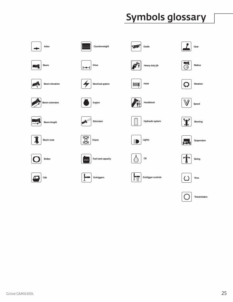
Symbols glossary
Drive
RotationElectrical system
Suspension
Fuel tank capacity
Tires
Engine
Brakes
Outrigger controls
Axles
Outriggers
Transmission
Frame
Steering
Lights
Boom elevation
Cab
Swing
Hydraulic system
Hoist
Boom nose
Radius
Boom extension
Boom length
Grade Gear
Boom
Counterweight
Speed
Oil
Extension
HookblockH
Heavy duty jib
Thisdocumentisnon-contractual.Constantimprovementandengineeringprogressmakeitnecessarythatwereservetherighttomakespecification,equipment,andpricechangeswithoutnotice.Illustrationsshownmayincludeoptionalequipmentandaccessoriesandmaynotincludeallstandardequipment.
AmericasBrazilAlphavilleMexicoMonterreyChileSantiago
Europe, Middle East, AfricaCzech RepublicNetvoriceFranceBaudemontCergyDecinesGermanyLangenfeldHungaryBudapestItalyLainateNetherlandsBredaPolandWarsaw
PortugalBaltarRussiaMoscowU.A.E.DubaiU.K.Buckingham
Asia - PacificAustraliaBrisbaneMelbourneSydneyChinaBeijingChengduGuangzhouIndiaDelhiHyderabadPuneKoreaSeoulPhilippinesMakati CitySingapore
FactoriesBrazilAlphavilleChinaTaiAnZhangjiagangFranceCharlieuLa ClayetteMoulinsGermanyWilhelmshavenIndiaPuneItalyNiella TanaroPortugalBaltarFânzeresSlovakiaSarisUSAManitowoc Port WashingtonShady Grove
Regional o ces
Manitowoc - Asia Pacific Shanghai, China Tel: +86 21 6457 0066Fax: +86 21 6457 4955
Manitowoc - Europe, Middle East, Africa Ecully, France Tel: +33 (0)4 72 18 20 20 Fax: +33 (0)4 72 18 20 00
Manitowoc - Americas Manitowoc, Wisconsin, USA Tel: +1 920 684 6621 Fax: +1 920 683 6277
Shady Grove, Pennsylvania, USA Tel: +1 717 597 8121 Fax: +1 717 597 4062
©2010 ManitowocPrinted in USAForm No. GMK6300LPart No. 10-008/2M/0910 www.manitowoc.com
Regional headquarters