grove rt890e
TRANSCRIPT
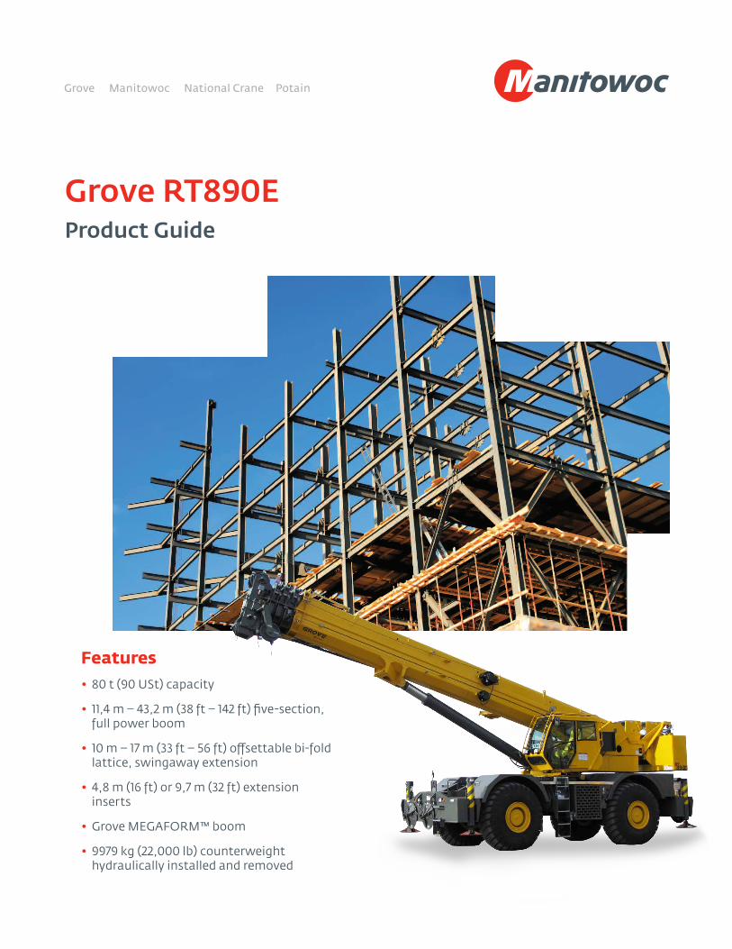
Features• 80 t (90 USt) capacity
• 11,4 m – 43,2 m (38 ft – 142 ft) five-section, full power boom
• 10 m – 17 m (33 ft – 56 ft) offsettable bi-fold lattice, swingaway extension
• 4,8 m (16 ft) or 9,7 m (32 ft) extension inserts
• Grove MEGAFORM™ boom
• 9979 kg (22,000 lb) counterweight hydraulically installed and removed
Grove RT890EProduct Guide
Features
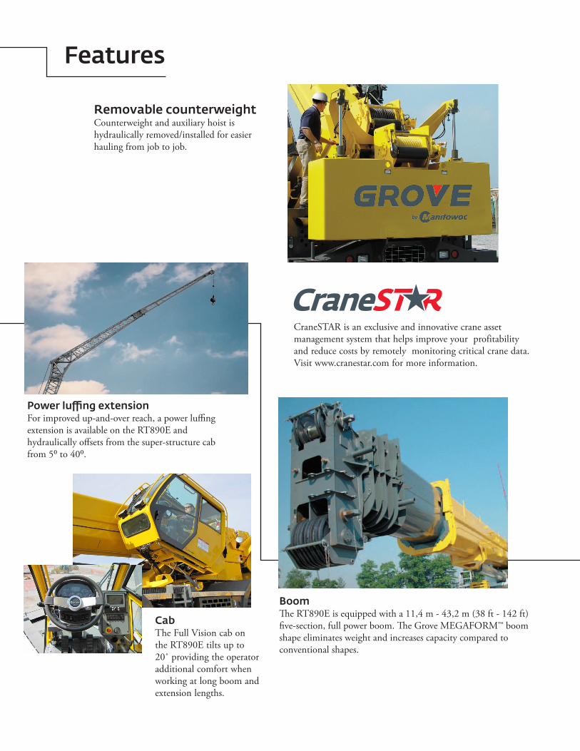
CabThe Full Vision cab on the RT890E tilts up to 20˚ providing the operator additional comfort when working at long boom and extension lengths.
BoomThe RT890E is equipped with a 11,4 m - 43,2 m (38 ft - 142 ft) five-section, full power boom. The Grove MEGAFORM™ boom shape eliminates weight and increases capacity compared to conventional shapes.
Removable counterweightCounterweight and auxiliary hoist is hydraulically removed/installed for easier hauling from job to job.
Power luffing extensionFor improved up-and-over reach, a power luffing extension is available on the RT890E and hydraulically offsets from the super-structure cab from 5⁰ to 40⁰.
CraneSTAR is an exclusive and innovative crane asset management system that helps improve your profitability and reduce costs by remotely monitoring critical crane data. Visit www.cranestar.com for more information.
Contents
Features 2
Specifications 4
Dimensions and weights 7
Working range 8
Mode A vs. (Mode B) 9
Load chart (Mode B) 10
Load chart fixed offsettable swingaway 11
Working range with one 16 ft insert 12
Working range with two 16 ft inserts 13
Load charts fixed offsettable swingaway with inserts 14
Load charts (Mode A) 15
Luffing extension charts 17
Load handling 21
4
Specifications
Load momentand anti-two block system
Standard “Graphic Display” load moment and anti-two block system with audio-visual warning and control lever lockout. These systems provide electronic display of boom angle, length, radius, tip height, relative load moment, maximum permissible load, load indication and warning of impending two-block condition. The standard Work Area Definition System allows the operator to pre-select and define safe working areas. If the crane approaches the pre-set limits, audio-visual warnings aid the operator in avoiding job-site obstructions.
Cab
20° tilt, Full-vision, all-steel fabricated with acoustical lining and tinted safety glass throughout. Deluxe seat incorporates armrest-mounted hydraulic single-axis controllers. Tilt/telescoping steering wheel with various controls incorporated into the steering column. Other standard features include:, hot water heater, cab circulating air fan, sliding side and rear windows, sliding skylight with electric wiper and sunscreen, electric windshield wash/wipe, fire extinguisher, seat belt, air conditioning, and dual cab mounted work lights.
Swing
Two speed, planetary swing drive with foot applied multi-disc wet brake. Spring applied, hydraulically released swing brake. Single position mechanical house lock, operated from cab. Maximum speed: 2.0 rpm.
Counterweight
9979 kg (22,000 lb). Hydraulically installed and removed.
Superstructure (continued)
Superstructure
Boom
11,4 m – 43,2 m (38 ft – 142 ft) five-section, sequenced synchronized full power boom with A and B mode.Maximum tip height: 45,7 m (150 ft).
*Optional lattice extension
10 m – 17 m (33 ft – 56 ft) offsettable bi-fold lattice swingaway extension. Offsets 0°, 20° and 40°. Stows alongside base boom section.Maximum tip height: 62,7 m (206 ft).
*Optional lattice extension
10 m – 17 m (33 ft – 56 ft) hydraulically offsettable bi-fold lattice swingaway extension. Offsets from 0° to 40°. Stows alongside base boom section.Maximum tip height: 62,7 m (206 ft).
*Optional lattice extension inserts
(2) x 4,8 m (16 ft) lattice extension inserts. Installs between the boom nose and bi-fold extension, non-stowable.Maximum tip height: 72,5 m (238 ft)
Boom nose
Five nylatron sheaves mounted on heavy duty tapered roller bearings with removable pin-type rope guards. Quick reeving type boom nose. Removable auxiliary boom nose with removable pin type rope guard.
Boom elevation
One double acting hydraulic cylinder with integral holding valve provides elevation from -3° to +78°.
*Denotes optional equipment
5Grove RT890E
Specifications
Superstructure (continued)
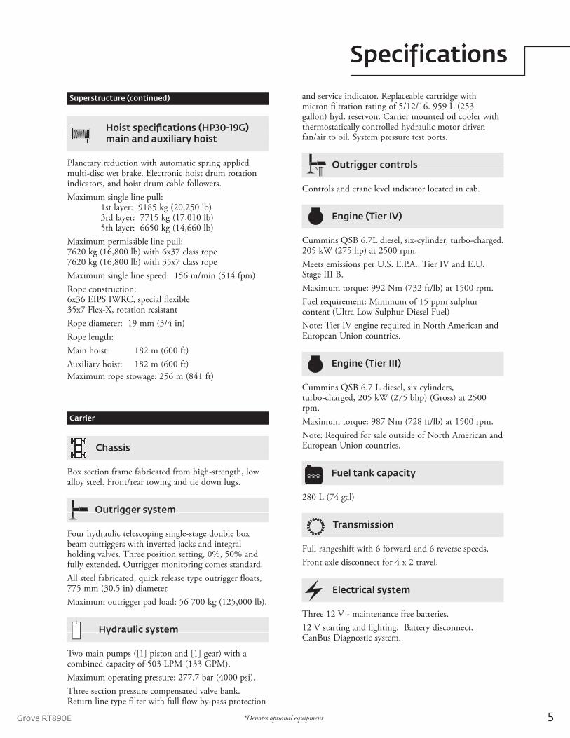
Hoist specifications (HP30-19G)main and auxiliary hoist
Planetary reduction with automatic spring applied multi-disc wet brake. Electronic hoist drum rotation indicators, and hoist drum cable followers.Maximum single line pull: 1st layer: 9185 kg (20,250 lb) 3rd layer: 7715 kg (17,010 lb) 5th layer: 6650 kg (14,660 lb)Maximum permissible line pull: 7620 kg (16,800 lb) with 6x37 class rope7620 kg (16,800 lb) with 35x7 class ropeMaximum single line speed: 156 m/min (514 fpm)Rope construction: 6x36 EIPS IWRC, special flexible35x7 Flex-X, rotation resistantRope diameter: 19 mm (3/4 in)Rope length: Main hoist: 182 m (600 ft)Auxiliary hoist: 182 m (600 ft)Maximum rope stowage: 256 m (841 ft)
Carrier
Chassis
Box section frame fabricated from high-strength, low alloy steel. Front/rear towing and tie down lugs.
Outrigger system
Four hydraulic telescoping single-stage double box beam outriggers with inverted jacks and integral holding valves. Three position setting, 0%, 50% and fully extended. Outrigger monitoring comes standard.All steel fabricated, quick release type outrigger floats, 775 mm (30.5 in) diameter.Maximum outrigger pad load: 56 700 kg (125,000 lb).
Hydraulic system
Two main pumps ([1] piston and [1] gear) with a combined capacity of 503 LPM (133 GPM).Maximum operating pressure: 277.7 bar (4000 psi).Three section pressure compensated valve bank. Return line type filter with full flow by-pass protection
and service indicator. Replaceable cartridge with micron filtration rating of 5/12/16. 959 L (253 gallon) hyd. reservoir. Carrier mounted oil cooler with thermostatically controlled hydraulic motor driven fan/air to oil. System pressure test ports.
Outrigger controls
Controls and crane level indicator located in cab.
Engine (Tier IV)
Cummins QSB 6.7L diesel, six-cylinder, turbo-charged. 205 kW (275 hp) at 2500 rpm.Meets emissions per U.S. E.P.A., Tier IV and E.U. Stage III B.Maximum torque: 992 Nm (732 ft/lb) at 1500 rpm.Fuel requirement: Minimum of 15 ppm sulphur content (Ultra Low Sulphur Diesel Fuel) Note: Tier IV engine required in North American and European Union countries.
Engine (Tier III)
Cummins QSB 6.7 L diesel, six cylinders, turbo-charged, 205 kW (275 bhp) (Gross) at 2500 rpm.Maximum torque: 987 Nm (728 ft/lb) at 1500 rpm.Note: Required for sale outside of North American and European Union countries.
Fuel tank capacity
280 L (74 gal)
Transmission
Full rangeshift with 6 forward and 6 reverse speeds.Front axle disconnect for 4 x 2 travel.
Electrical system
Three 12 V - maintenance free batteries.12 V starting and lighting. Battery disconnect. CanBus Diagnostic system.
*Denotes optional equipment
6
Specifications
Maximum speed
35 km/h (22 mph)
Gradeability (theoretical)
75% (Based on 52 607 kg [115,976 lb] GVW, 29.5 x 25 tires, 43,2 m [142 ft] boom, plus 17,0 m [56 ft] swingaway, 22,000 lb counterweight, 80 t [90 USt] hookblock and 9,1 t [10 USt] headache ball).
Miscellaneous standard equipment
Full width steel fenders, full length aluminum decking, dual rear view mirrors, hook-block tie down, electronic back-up alarm, light package, front stowage well, cab air conditioning, tachometer/hourmeter, rear wheel position indicator, 36,000 BTU hot water cab heater, hoist mirrors, engine distress A/V warning system, front/rear tie down and tow lugs, coolant sight level indicator, CraneSTAR asset management system.
*Optional equipment
• Auxiliary Lighting and Convenience Package: includes cab mounted amber flashing light, dual base boom mounted floodlights. LMI light bar (in cab), and rubber mat for stowage trough
• 360˚NYCstylemechanicalswinglock• RearPintlehook• Cabcontrolledcrossaxledifferentiallocks,(front
and rear)• PATeventrecorder• 3rdwrapindicatorformainand/orauxiliaryhoists• Windspeedindicator(wireless).•C.E.MarkConformance•ValuePackage:Includes33ft-56ftmanualbi-fold
swingaway, 360° swing lock, and auxiliary hoist package
•AuxiliaryHoistPackage:IncludesHP30-19Gauxiliary hoist with rotation indicator, cable follower, auxiliary hoist mirror and 185 m (607 ft) of non-rotational wire rope.
Carrier (continued)
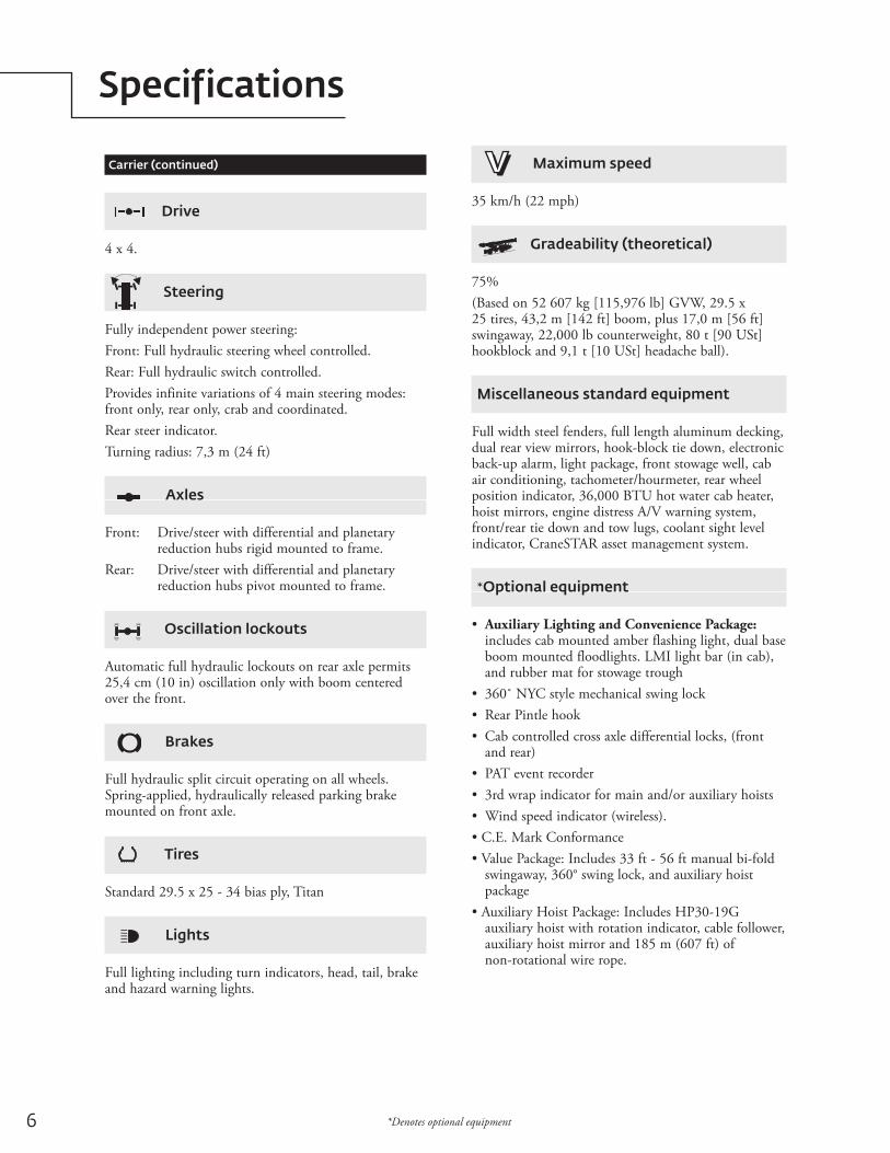
Drive
4 x 4.
Steering
Fully independent power steering:Front: Full hydraulic steering wheel controlled.Rear: Full hydraulic switch controlled.Provides infinite variations of 4 main steering modes: front only, rear only, crab and coordinated.Rear steer indicator.Turning radius: 7,3 m (24 ft)
Axles
Front: Drive/steer with differential and planetary reduction hubs rigid mounted to frame.Rear: Drive/steer with differential and planetary reduction hubs pivot mounted to frame.
Oscillation lockouts
Automatic full hydraulic lockouts on rear axle permits 25,4 cm (10 in) oscillation only with boom centered over the front.
Brakes
Full hydraulic split circuit operating on all wheels. Spring-applied, hydraulically released parking brake mounted on front axle.
Tires
Standard 29.5 x 25 - 34 bias ply, Titan
Lights
Full lighting including turn indicators, head, tail, brake and hazard warning lights.
*Denotes optional equipment
7Grove RT890E
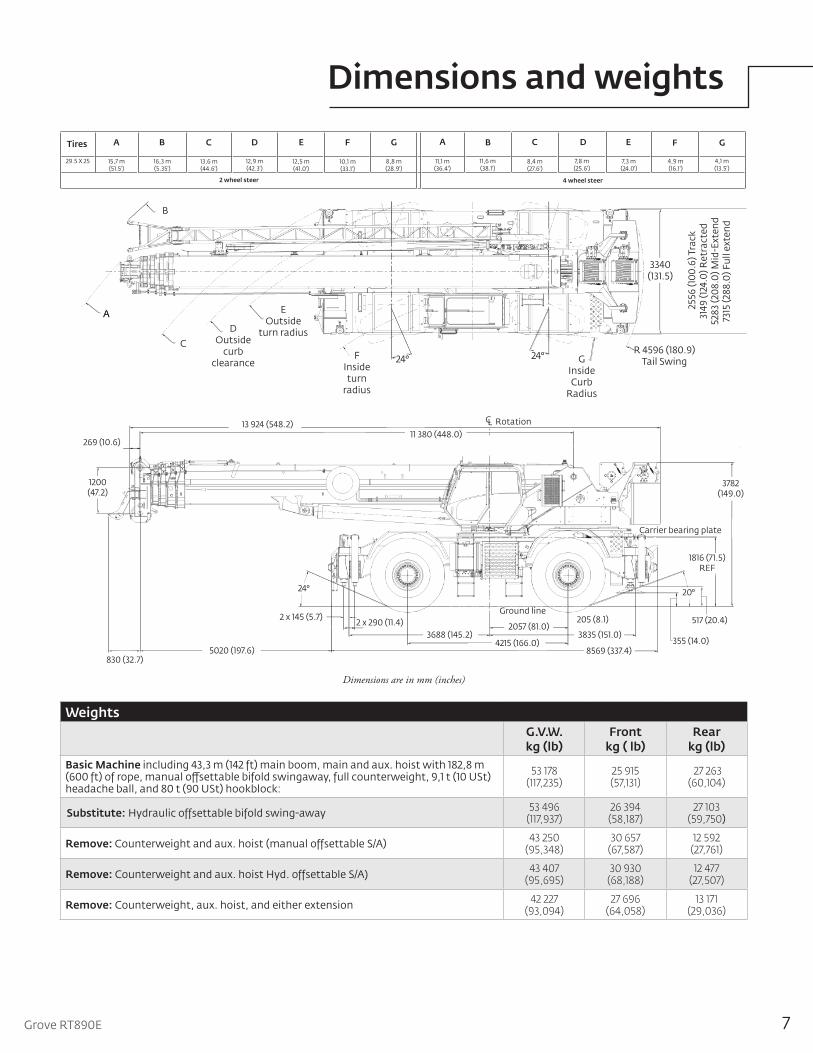
Dimensions and weights
Dimensions are in mm (inches)
Tires E FCBA D G
29.5 X 25 15,7 m(51.5')
16,3 m(5.35')
13,6 m(44.6')
12,9 m(42.3')
12,5 m(41.0')
10,1 m(33.1')
8,8 m(28.9')
A B C D E F G
11,1 m(36.4')
11,6 m(38.1')
8,4 m(27.6')
7,8 m(25.6')
7,3 m(24.0')
4,9 m(16.1')
4,1 m(13.5')
2 wheel steer 4 wheel steer
269 (10.6)
830 (32.7)
2 x 145 (5.7)2 x 290 (11.4) 205 (8.1)
13 924 (548.2)11 380 (448.0)
1200 (47.2)
5020 (197.6)
3688 (145.2)2057 (81.0)
4215 (166.0)8569 (337.4)
3835 (151.0)
24° 20°
1816 (71.5) REF
3782 (149.0)
355 (14.0)
517 (20.4)Ground line
CL Rotation
Carrier bearing plate
A
C
DOutside
curb clearance
A
FInside turn
radius
EOutside
turn radius
24°R 4596 (180.9)
Tail Swing
B
GInside Curb
Radius
24°
3340 (131.5)
255
6 (1
00.6
) Tra
ck31
49 (1
24.0
) Ret
ract
ed52
83 (2
08.0
) Mid
-Ext
end
7315
(288
.0) F
ull e
xten
dWeights
G.V.W.kg (lb)
Frontkg ( lb)
Rearkg (lb)
Basic Machine including 43,3 m (142 ft) main boom, main and aux. hoist with 182,8 m (600 ft) of rope, manual offsettable bifold swingaway, full counterweight, 9,1 t (10 USt) headache ball, and 80 t (90 USt) hookblock:
53 178(117,235)
25 915(57,131)
27 263(60,104)
Substitute: Hydraulic offsettable bifold swing-away 53 496(117,937)
26 394(58,187)
27 103(59,750)
Remove: Counterweight and aux. hoist (manual offsettable S/A) 43 250(95,348)
30 657(67,587)
12 592(27,761)
Remove: Counterweight and aux. hoist Hyd. offsettable S/A) 43 407(95,695)
30 930(68,188)
12 477(27,507)
Remove: Counterweight, aux. hoist, and either extension 42 227(93,094)
27 696(64,058)
13 171(29,036)
8
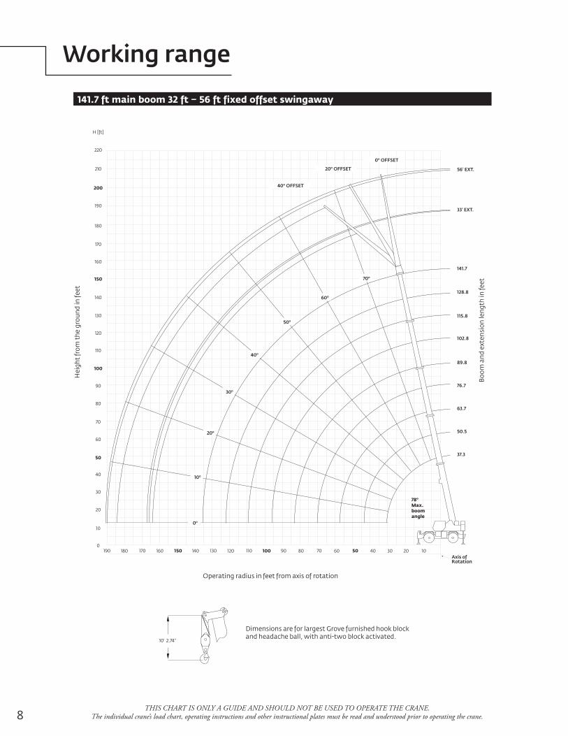
Working range
THIS CHART IS ONLY A GUIDE AND SHOULD NOT BE USED TO OPERATE THE CRANE. The individual crane’s load chart, operating instructions and other instructional plates must be read and understood prior to operating the crane.
141.7 ft main boom 32 ft – 56 ft fixed offset swingaway
180
190
210
220
200
H [ft]
170
160
150
140
130
120
110
100
90
80
70
60
50
40
30
20
10
0190 170 150 130 110 90 70 50180 160 140 120 100 80 60 40 30 20 10
Hei
ght
from
the
gro
und
in fe
et
Operating radius in feet from axis of rotation
Boo
m a
nd e
xten
sion
leng
th in
feet
56' EXT.
33' EXT.
141.7
128.8
115.8
102.8
89.8
76.7
63.7
50.5
37.3
10' 2.74"
Dimensions are for largest Grove furnished hook blockand headache ball, with anti-two block activated.
Axis ofRotation
78o
Max.boomangle
0o OFFSET
20o OFFSET
40o OFFSET
60o
50o
40o
30o
20o
10o
0o
70o
9Grove RT890E
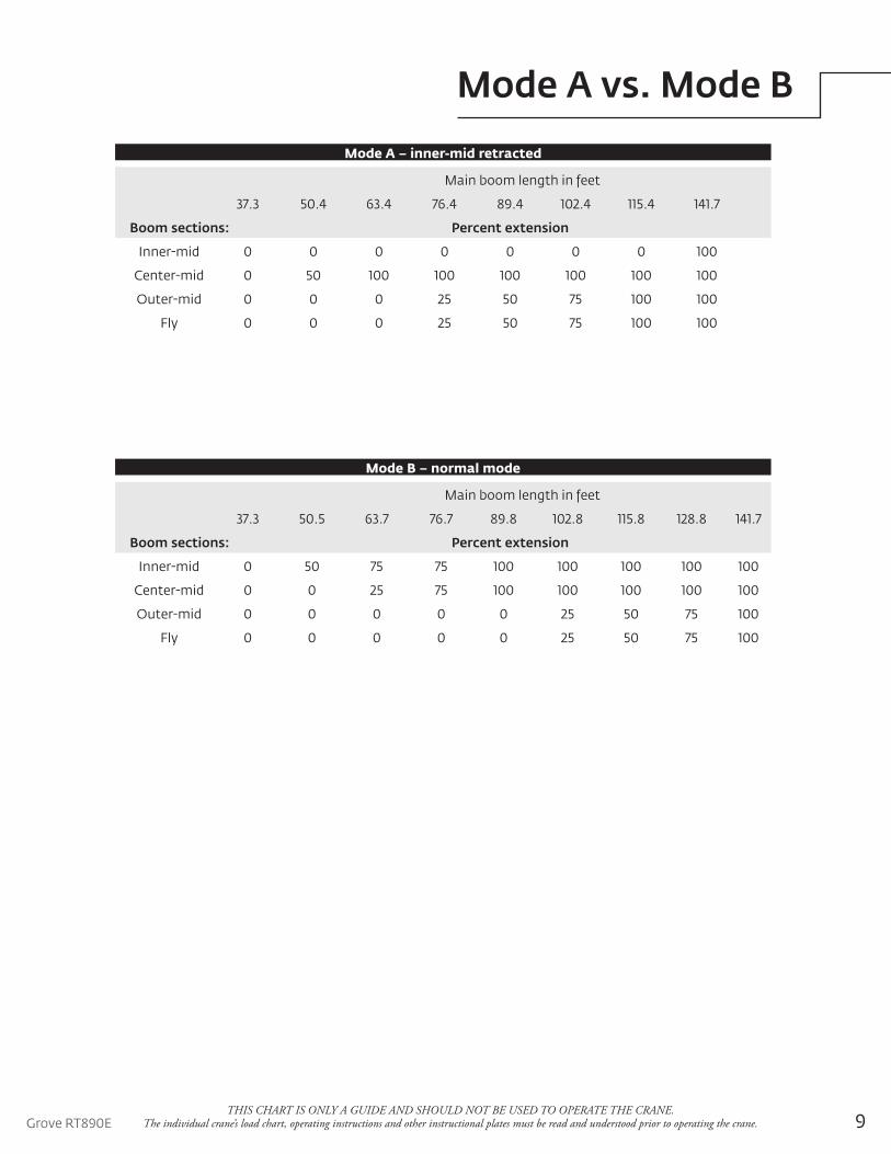
Mode A vs. Mode B
THIS CHART IS ONLY A GUIDE AND SHOULD NOT BE USED TO OPERATE THE CRANE. The individual crane’s load chart, operating instructions and other instructional plates must be read and understood prior to operating the crane.
Main boom length in feet
37.3 50.4 63.4 76.4 89.4 102.4 115.4 141.7
Boom sections: Percent extension
Inner-mid 0 0 0 0 0 0 0 100
Center-mid 0 50 100 100 100 100 100 100
Outer-mid 0 0 0 25 50 75 100 100
Fly 0 0 0 25 50 75 100 100
Mode A – inner-mid retracted
Main boom length in feet
37.3 50.5 63.7 76.7 89.8 102.8 115.8 128.8 141.7
Boom sections: Percent extension
Inner-mid 0 50 75 75 100 100 100 100 100
Center-mid 0 0 25 75 100 100 100 100 100
Outer-mid 0 0 0 0 0 25 50 75 100
Fly 0 0 0 0 0 25 50 75 100
Mode B – normal mode
10
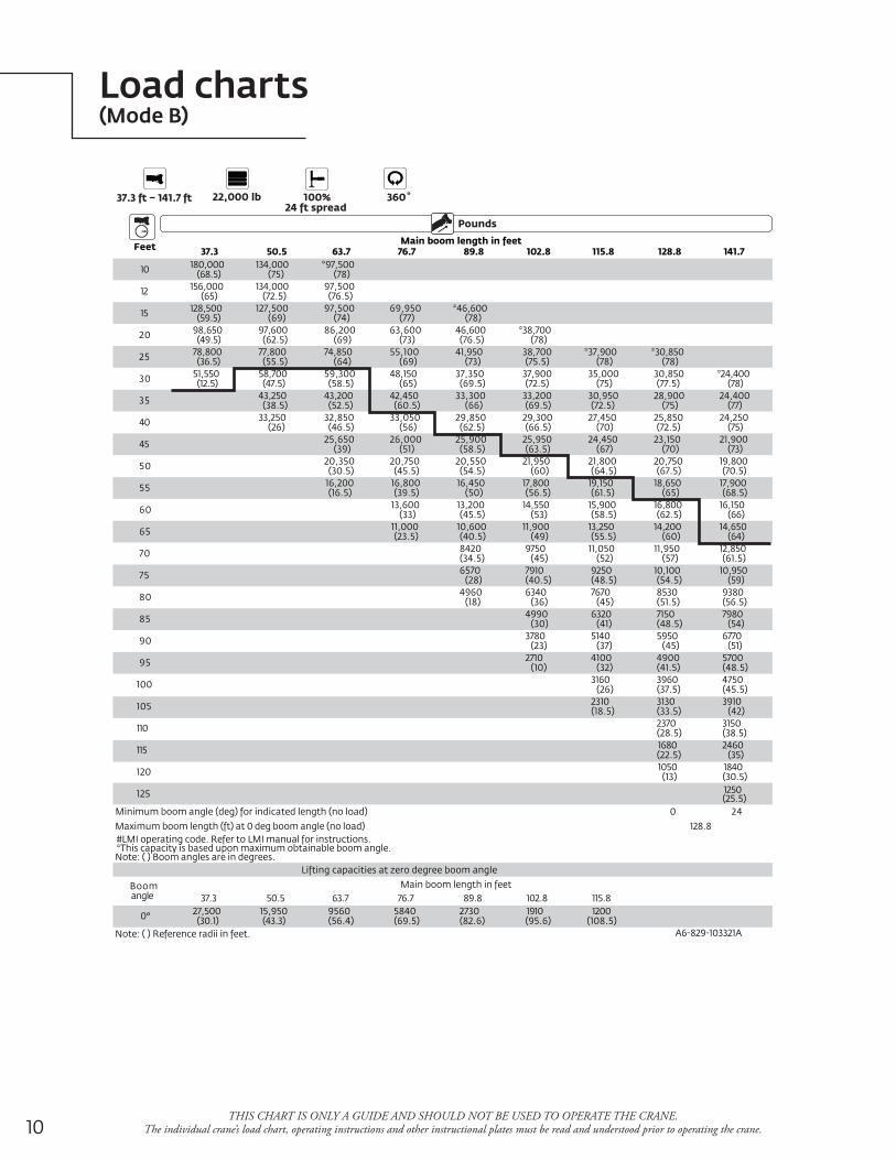
Load charts(Mode B)
THIS CHART IS ONLY A GUIDE AND SHOULD NOT BE USED TO OPERATE THE CRANE. The individual crane’s load chart, operating instructions and other instructional plates must be read and understood prior to operating the crane.
Pounds
37.3 ft – 141.7 ft 22,000 lb 100%24 ft spread
360˚
FeetMain boom length in feet
37.3 50.5 63.7 76.7 89.8 102.8 115.8 128.8 141.7
10 180,000(68.5)
134,000(75)
*97,500(78)
12 156,000(65)
134,000(72.5)
97,500(76.5)
15 128,500(59.5)
127,500(69)
97,500(74)
69,950(77)
*46,600(78)
20 98,650(49.5)
97,600(62.5)
86,200(69)
63,600(73)
46,600(76.5)
*38,700(78)
25 78,800(36.5)
77,800(55.5)
74,850(64)
55,100(69)
41,950(73)
38,700(75.5)
*37,900(78)
*30,850(78)
30 51,550(12.5)
58,700(47.5)
59,300(58.5)
48,150(65)
37,350(69.5)
37,900(72.5)
35,000(75)
30,850(77.5)
*24,400(78)
35 43,250(38.5)
43,200(52.5)
42,450(60.5)
33,300(66)
33,200(69.5)
30,950(72.5)
28,900(75)
24,400(77)
40 33,250(26)
32,850(46.5)
33,050(56)
29,850(62.5)
29,300(66.5)
27,450(70)
25,850(72.5)
24,250(75)
45 25,650(39)
26,000(51)
25,900(58.5)
25,950(63.5)
24,450(67)
23,150(70)
21,900(73)
50 20,350(30.5)
20,750(45.5)
20,550(54.5)
21,950(60)
21,800(64.5)
20,750(67.5)
19,800(70.5)
55 16,200(16.5)
16,800(39.5)
16,450(50)
17,800(56.5)
19,150(61.5)
18,650(65)
17,900(68.5)
60 13,600(33)
13,200(45.5)
14,550(53)
15,900(58.5)
16,800(62.5)
16,150(66)
65 11,000(23.5)
10,600(40.5)
11,900(49)
13,250(55.5)
14,200(60)
14,650(64)
70 8420(34.5)
9750(45)
11,050(52)
11,950(57)
12,850(61.5)
75 6570(28)
7910(40.5)
9250(48.5)
10,100(54.5)
10,950(59)
80 4960(18)
6340(36)
7670(45)
8530(51.5)
9380(56.5)
85 4990(30)
6320(41)
7150(48.5)
7980(54)
90 3780(23)
5140(37)
5950(45)
6770(51)
95 2710(10)
4100(32)
4900(41.5)
5700(48.5)
100 3160(26)
3960(37.5)
4750(45.5)
105 2310(18.5)
3130(33.5)
3910(42)
110 2370(28.5)
3150(38.5)
115 1680(22.5)
2460(35)
120 1050(13)
1840(30.5)
125 1250(25.5)
Minimum boom angle (deg) for indicated length (no load) 0 24Maximum boom length (ft) at 0 deg boom angle (no load) 128.8#LMI operating code. Refer to LMI manual for instructions.*This capacity is based upon maximum obtainable boom angle.Note: ( ) Boom angles are in degrees.
Lifting capacities at zero degree boom angle
Boomangle
Main boom length in feet37.3 50.5 63.7 76.7 89.8 102.8 115.8
0° 27,500(30.1)
15,950(43.3)
9560(56.4)
5840(69.5)
2730(82.6)
1910(95.6)
1200(108.5)
Note: ( ) Reference radii in feet. A6-829-103321A
11Grove RT890E
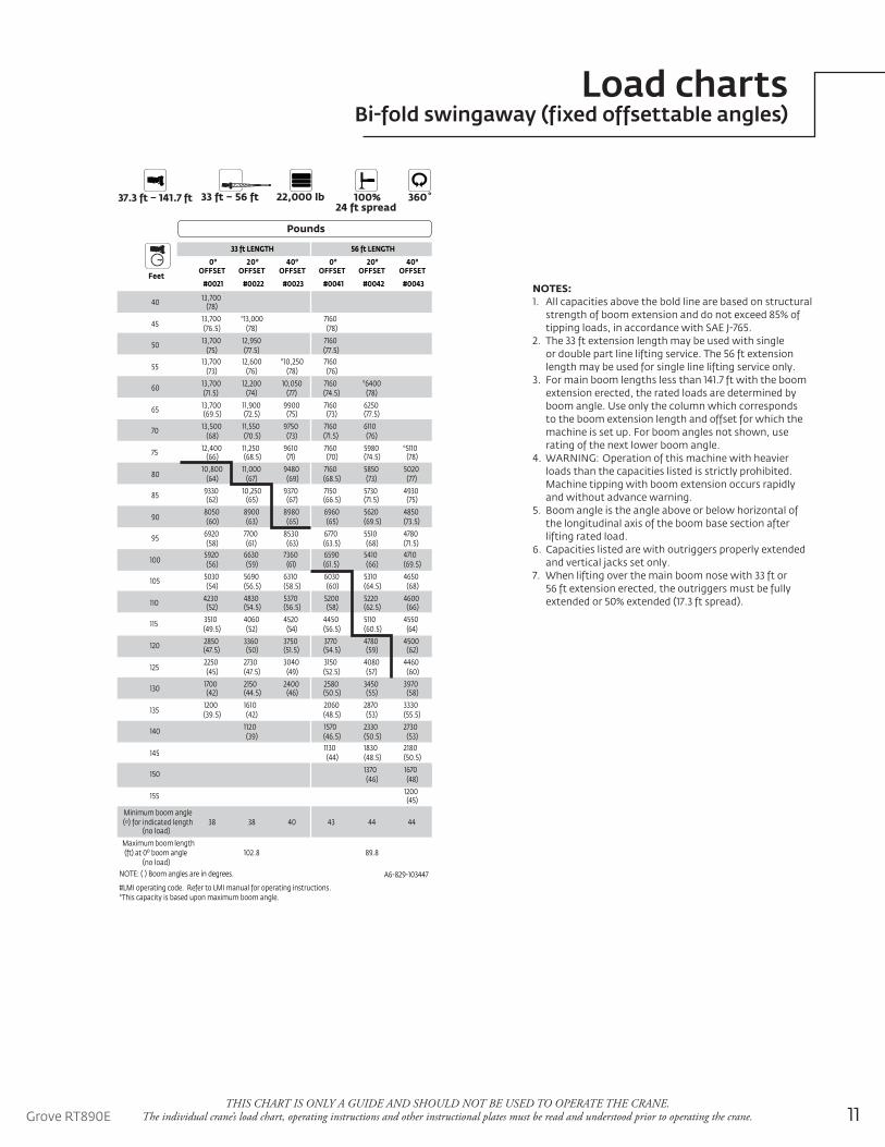
Load chartsBi-fold swingaway (fixed offsettable angles)
THIS CHART IS ONLY A GUIDE AND SHOULD NOT BE USED TO OPERATE THE CRANE. The individual crane’s load chart, operating instructions and other instructional plates must be read and understood prior to operating the crane.
Pounds
37.3 ft – 141.7 ft 22,000 lb33 ft – 56 ft 100%24 ft spread
360˚
Feet
33 ft LENGTH 56 ft LENGTH
0o
OFFSET20o
OFFSET40o
OFFSET0o
OFFSET20o
OFFSET40o
OFFSET
#0021 #0022 #0023 #0041 #0042 #0043
40 13,700(78)
4513,700(76.5)
*13,000(78)
7160(78)
50 13,700(75)
12,950(77.5)
7160(77.5)
5513,700
(73)12,600
(76)*10,250
(78)7160(76)
60 13,700(71.5)
12,200(74)
10,050(77)
7160(74.5)
*6400(78)
65 13,700(69.5)
11,900(72.5)
9900(75)
7160(73)
6250(77.5)
70 13,500(68)
11,550(70.5)
9750(73)
7160(71.5)
6110(76)
75 12,400(66)
11,250(68.5)
9610(71)
7160(70)
5980(74.5)
*5110(78)
8010,800
(64)11,000
(67)9480
(69)7160(68.5)
5850(73)
5020(77)
85 9330(62)
10,250(65)
9370(67)
7150(66.5)
5730(71.5)
4930(75)
908050(60)
8900(63)
8980(65)
6960(65)
5620(69.5)
4850(73.5)
95 6920(58)
7700(61)
8530(63)
6770(63.5)
5510(68)
4780(71.5)
1005920(56)
6630(59)
7360(61)
6590(61.5)
5410(66)
4710(69.5)
105 5030(54)
5690(56.5)
6310(58.5)
6030(60)
5310(64.5)
4650(68)
110 4230(52)
4830(54.5)
5370(56.5)
5200(58)
5220(62.5)
4600(66)
115 3510(49.5)
4060(52)
4520(54)
4450(56.5)
5110(60.5)
4550(64)
120 2850(47.5)
3360(50)
3750(51.5)
3770(54.5)
4780(59)
4500(62)
1252250(45)
2730(47.5)
3040(49)
3150(52.5)
4080(57)
4460(60)
130 1700(42)
2150(44.5)
2400(46)
2580(50.5)
3450(55)
3970(58)
1351200(39.5)
1610(42)
2060(48.5)
2870(53)
3330(55.5)
140 1120(39)
1570(46.5)
2330(50.5)
2730(53)
1451130(44)
1830(48.5)
2180(50.5)
150 1370(46)
1670(48)
155 1200(45)
Minimum boom angle(o) for indicated length
(no load)38 38 40 43 44 44
Maximum boom length(ft) at 0o boom angle
(no load)102.8 89.8
NOTE: ( ) Boom angles are in degrees. A6-829-103447
#LMI operating code. Refer to LMI manual for operating instructions.*This capacity is based upon maximum boom angle.
NOTES:1. All capacities above the bold line are based on structural
strength of boom extension and do not exceed 85% of tipping loads, in accordance with SAE J-765.
2. The 33 ft extension length may be used with single or double part line lifting service. The 56 ft extension length may be used for single line lifting service only.
3. For main boom lengths less than 141.7 ft with the boom extension erected, the rated loads are determined by boom angle. Use only the column which corresponds to the boom extension length and offset for which the machine is set up. For boom angles not shown, use rating of the next lower boom angle.
4. WARNING: Operation of this machine with heavier loads than the capacities listed is strictly prohibited. Machine tipping with boom extension occurs rapidly and without advance warning.
5. Boom angle is the angle above or below horizontal of the longitudinal axis of the boom base section after lifting rated load.
6. Capacities listed are with outriggers properly extended and vertical jacks set only.
7. When lifting over the main boom nose with 33 ft or 56 ft extension erected, the outriggers must be fully extended or 50% extended (17.3 ft spread).
12
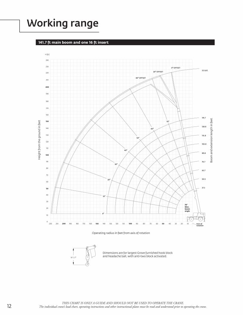
Working range
THIS CHART IS ONLY A GUIDE AND SHOULD NOT BE USED TO OPERATE THE CRANE. The individual crane’s load chart, operating instructions and other instructional plates must be read and understood prior to operating the crane.
141.7 ft main boom and one 16 ft insert
180
190
210
220
230
240
200
H [ft]
170
160
150
140
130
120
110
100
90
80
70
60
50
40
30
20
10
0220 200 180 160 140 120 100 80210 190 170 150 130 110 90 70 60 50 40 30 20 10
Hei
ght
from
the
gro
und
in fe
et
Operating radius in feet from axis of rotation
Boo
m a
nd e
xten
sion
leng
th in
feet
10' 2.7"
Dimensions are for largest Grove furnished hook blockand headache ball, with anti-two block activated.
Axis ofrotation
72' EXT.
141.7
128.8
115.8
102.8
89.8
76.7
63.7
50.5
37.3
78o
Max.boomangle
0o OFFSET
20o OFFSET
40o OFFSET
60o
50o
40o
30o
20o
10o
0o
70o
13Grove RT890E
Working range
THIS CHART IS ONLY A GUIDE AND SHOULD NOT BE USED TO OPERATE THE CRANE. The individual crane’s load chart, operating instructions and other instructional plates must be read and understood prior to operating the crane.
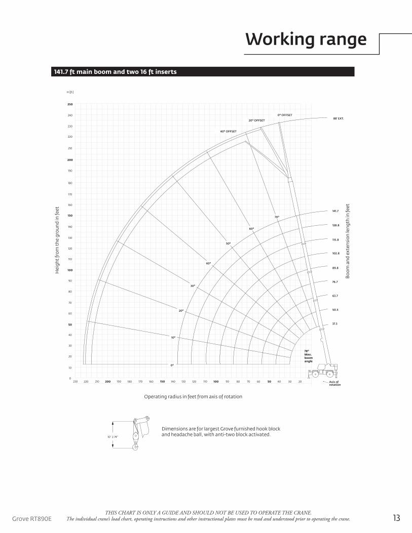
141.7 ft main boom and two 16 ft inserts
180
190
210
220
230
240
250
200
H [ft]
170
160
150
140
130
120
110
100
90
80
70
60
50
40
30
20
10
0230 210 190 170 150 130 110 90220 200 180 160 140 120 100 80 70 60 50 40 30 20
Hei
ght
from
the
gro
und
in fe
et
Operating radius in feet from axis of rotation
Boo
m a
nd e
xten
sion
leng
th in
feet
10' 2.74"
Dimensions are for largest Grove furnished hook blockand headache ball, with anti-two block activated.
Axis ofrotation
88' EXT.
141.7
128.8
115.8
102.8
89.8
76.7
63.7
50.5
37.3
78o
Max.boomangle
0o OFFSET
20o OFFSET
40o OFFSET
60o
50o
40o
30o
20o
10o
0o
70o
14
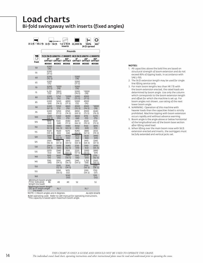
Load chartsBi-fold swingaway with inserts (fixed angles)
THIS CHART IS ONLY A GUIDE AND SHOULD NOT BE USED TO OPERATE THE CRANE. The individual crane’s load chart, operating instructions and other instructional plates must be read and understood prior to operating the crane.
Pounds
37.3 ft – 141.7 ft 1 or 2 16 ft inserts
22,000 lb33 ft – 56 ft 100%24 ft spread
360˚
Feet
72 ft (56 ft LENGTH + 1 INSERT) 88 ft (56 ft LENGTH + 2 INSERTS)0°
OFFSET20°
OFFSET40°
OFFSET0°
OFFSET20°
OFFSET40°
OFFSET#0064 #0065 #0066 #0084 #0085 #0086
50 6300(78)
55 6300(77.5)
60 6300(76.5)
5000(78)
65 6300(75)
5000(77.5)
70 6300(73.5)
*6100(78)
5000(76)
75 6,00(72)
5860(77.5)
5000(74.5)
*4900(78)
80 6300(70.5)
5750(76)
*5000(78)
5000(73.5)
4900(77.5)
85 6300(69)
5650(74.5)
4890(77.5)
5000(72)
4900(76)
90 6300(67.5)
5550(73)
4820(76)
4900(70.5)
4900(74.5)
*4800(78)
95 6300(66)
5450(71.5)
4760(74.5)
4850(69.5)
4900(73.5)
4640(76.5)
100 6300(64.5)
5360(70)
4690(73)
4800(68)
4710(72)
4370(75)
105 5810(63)
5120(68)
4580(71.5)
4670(66.5)
4420(70.5)
4120(73.5)
110 5030(61.5)
4880(66.5)
4480(69.5)
4550(65)
4130(69)
3870(72)
115 4320(59.5)
4620(65)
4270(68)
4240(63.5)
3880(67.5)
3650(70.5)
120 3680(58)
4370(63.5)
4060(66)
3850(62)
3630(66)
3440(69)
125 3100(56.5)
4110(61.5)
3870(64.5)
3260(60.5)
3410(64.5)
3240(67.5)
130 2560(54.5)
3500(60)
3680(62.5)
2720(59)
3190(63)
3050(65.5)
135 2070(53)
2940(58)
3510(60.5)
2220(57.5)
3000(61.5)
2880(64)
140 1610(51)
2420(56)
2980(58.5)
1760(56)
2630(60)
2710(62.5)
145 1190(49)
1950(54.5)
2440(56.5)
1340(54.5)
2,150(58)
2560(60.5)
150 1500(52.5)
1930(54.5)
1700(56.5)
2210(58.5)
155 1090(50.5)
1470(52)
1290(54.5)
1750(57)
160 1030(50)
1310(55)
Minimum boom angle(°) for indicated length (no load)
48 49 49 52 53
Maximum boom length(ft) at 0° boom angle
(no load)76.7 76.7
NOTE: ( ) Boom angles are in degrees. A6-829-103478#LMI operating code. Refer to LMI manual for operating instructions.*This capacity is based upon maximum boom angle.
NOTES:1. All capacities above the bold line are based on
structural strength of boom extension and do not exceed 85% of tipping loads, in accordance with SAE J-765.
2. The 56 ft extension length may be used for single line lifting service only.
3. For main boom lengths less than 141.7 ft with the boom extension erected, the rated loads are determined by boom angle. Use only the column which corresponds to the boom extension length and offset for which the machine is set up. For boom angles not shown, use rating of the next lower boom angle.
4. WARNING: Operation of this machine with heavier loads than the capacities listed is strictly prohibited. Machine tipping with boom extension occurs rapidly and without advance warning.
5. Boom angle is the angle above or below horizontal of the longitudinal axis of the boom base section after lifting rated load.
6. When lifting over the main boom nose with 56 ft extension erected and inserts, the outriggers must be fully extended and vertical jacks set.
15Grove RT890E
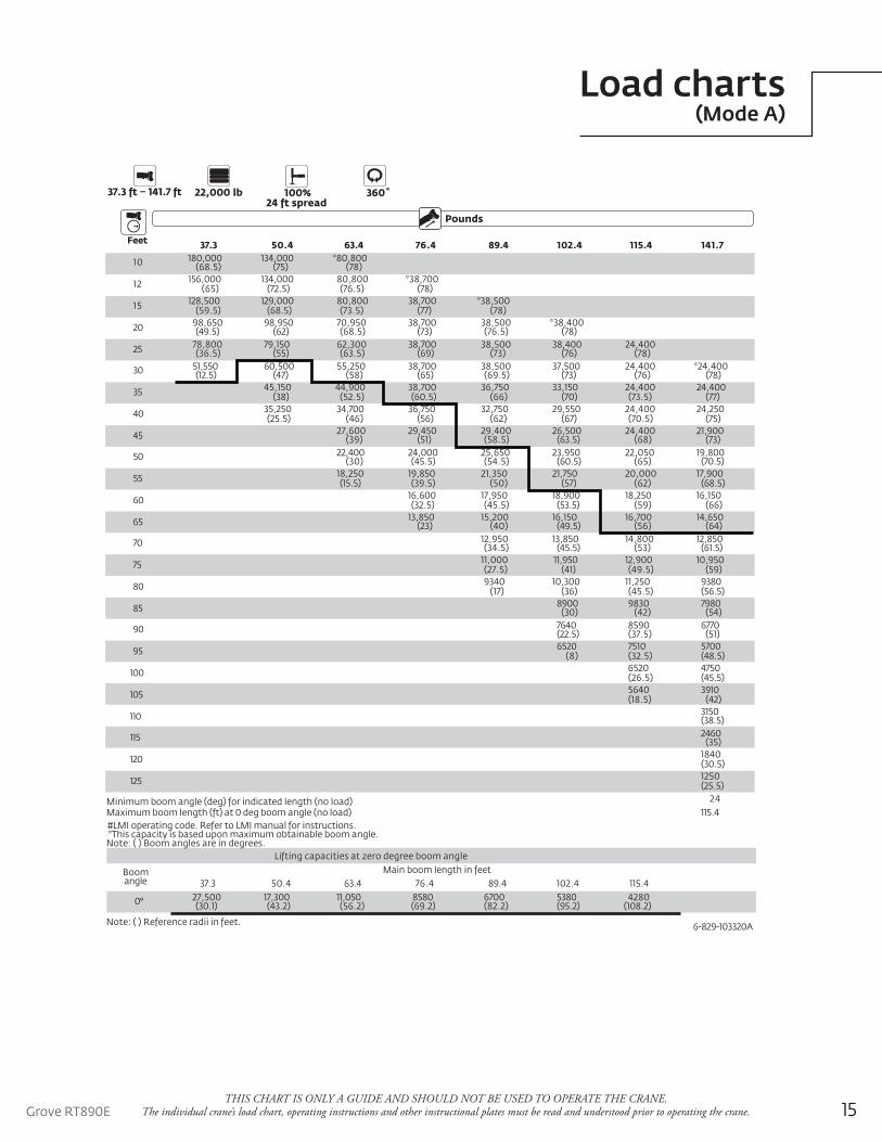
Load charts(Mode A)
THIS CHART IS ONLY A GUIDE AND SHOULD NOT BE USED TO OPERATE THE CRANE. The individual crane’s load chart, operating instructions and other instructional plates must be read and understood prior to operating the crane.
Pounds
37.3 ft – 141.7 ft 22,000 lb 100%24 ft spread
360˚
Feet 37.3 50.4 63.4 76.4 89.4 102.4 115.4 141.7
10 180,000(68.5)
134,000(75)
*80,800(78)
12 156,000(65)
134,000(72.5)
80,800(76.5)
*38,700(78)
15 128,500(59.5)
129,000(68.5)
80,800(73.5)
38,700(77)
*38,500(78)
20 98,650(49.5)
98,950(62)
70,950(68.5)
38,700(73)
38,500(76.5)
*38,400(78)
25 78,800(36.5)
79,150(55)
62,300(63.5)
38,700(69)
38,500(73)
38,400(76)
24,400(78)
30 51,550(12.5)
60,500(47)
55,250(58)
38,700(65)
38,500(69.5)
37,500(73)
24,400(76)
*24,400(78)
35 45,150(38)
44,900(52.5)
38,700(60.5)
36,750(66)
33,150(70)
24,400(73.5)
24,400(77)
40 35,250(25.5)
34,700(46)
36,750(56)
32,750(62)
29,550(67)
24,400(70.5)
24,250(75)
45 27,600(39)
29,450(51)
29,400(58.5)
26,500(63.5)
24,400(68)
21,900(73)
50 22,400(30)
24,000(45.5)
25,650(54.5)
23,950(60.5)
22,050(65)
19,800(70.5)
55 18,250(15.5)
19,850(39.5)
21,350(50)
21,750(57)
20,000(62)
17,900(68.5)
60 16,600(32.5)
17,950(45.5)
18,900(53.5)
18,250(59)
16,150(66)
65 13,850(23)
15,200(40)
16,150(49.5)
16,700(56)
14,650(64)
70 12,950(34.5)
13,850(45.5)
14,800(53)
12,850(61.5)
75 11,000(27.5)
11,950(41)
12,900(49.5)
10,950(59)
80 9340(17)
10,300(36)
11,250(45.5)
9380(56.5)
85 8900(30)
9830(42)
7980(54)
90 7640(22.5)
8590(37.5)
6770(51)
95 6520(8)
7510(32.5)
5700(48.5)
100 6520(26.5)
4750(45.5)
105 5640(18.5)
3910(42)
110 3150(38.5)
115 2460(35)
120 1840(30.5)
125 1250(25.5)
Minimum boom angle (deg) for indicated length (no load) 24Maximum boom length (ft) at 0 deg boom angle (no load) 115.4
6-829-103320A
#LMI operating code. Refer to LMI manual for instructions.*This capacity is based upon maximum obtainable boom angle.Note: ( ) Boom angles are in degrees.
Lifting capacities at zero degree boom angle
Boomangle
Main boom length in feet37.3 50.4 63.4 76.4 89.4 102.4 115.4
0° 27,500(30.1)
17,300(43.2)
11,050(56.2)
8580(69.2)
6700(82.2)
5380(95.2)
4280(108.2)
Note: ( ) Reference radii in feet.
16
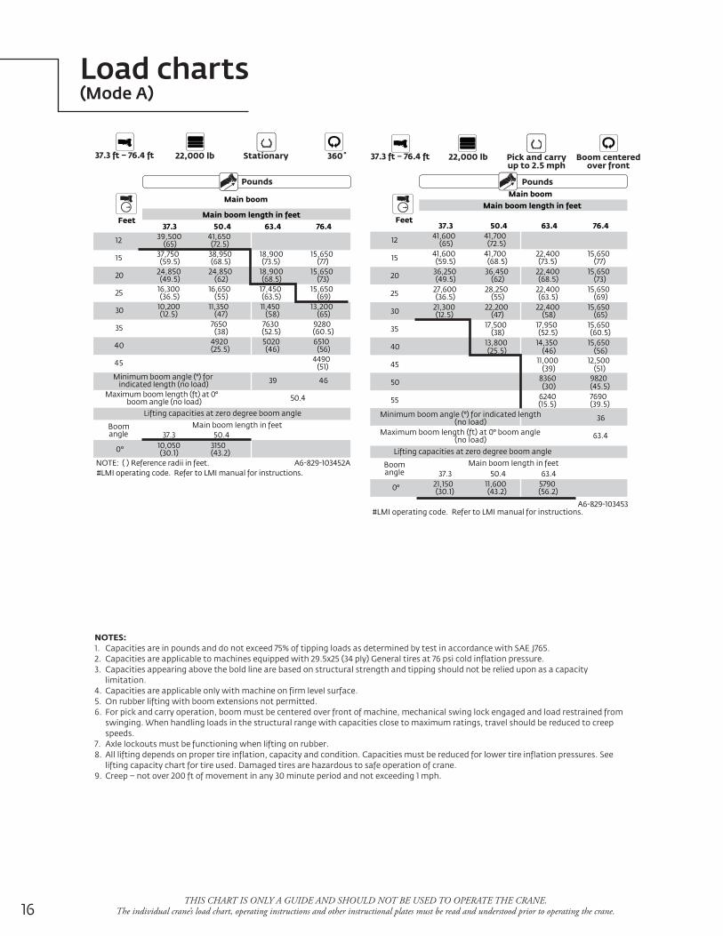
Load charts(Mode A)
THIS CHART IS ONLY A GUIDE AND SHOULD NOT BE USED TO OPERATE THE CRANE. The individual crane’s load chart, operating instructions and other instructional plates must be read and understood prior to operating the crane.
Pounds
37.3 ft – 76.4 ft 22,000 lb Stationary 360˚
Feet37.3 50.4 63.4 76.4
12 39,500(65)
41,650(72.5)
15 37,750(59.5)
38,950(68.5)
18,900(73.5)
15,650(77)
20 24,850(49.5)
24,850(62)
18,900(68.5)
15,650(73)
25 16,300(36.5)
16,650(55)
17,450(63.5)
15,650(69)
30 10,200(12.5)
11,350(47)
11,450(58)
13,200(65)
35 7650(38)
7630(52.5)
9280(60.5)
40 4920(25.5)
5020(46)
6510(56)
45 4490(51)
Minimum boom angle (°) forindicated length (no load) 39 46
Maximum boom length (ft) at 0°boom angle (no load) 50.4
Boomangle
Main boom length in feet37.3 50.4
0° 10,050(30.1)
3150(43.2)
NOTE: ( ) Reference radii in feet. A6-829-103452A#LMI operating code. Refer to LMI manual for instructions.
Main boom length in feet
Main boom
Lifting capacities at zero degree boom angle
Pounds
37.3 ft – 76.4 ft 22,000 lb Pick and carryup to 2.5 mph
Boom centeredover front
Feet37.3 50.4 63.4 76.4
12 41,600(65)
41,700(72.5)
15 41,600(59.5)
41,700(68.5)
22,400(73.5)
15,650(77)
20 36,250(49.5)
36,450(62)
22,400(68.5)
15,650(73)
25 27,600(36.5)
28,250(55)
22,400(63.5)
15,650(69)
30 21,300(12.5)
22,200(47)
22,400(58)
15,650(65)
35 17,500(38)
17,950(52.5)
15,650(60.5)
40 13,800(25.5)
14,350(46)
15,650(56)
45 11,000(39)
12,500(51)
50 8360(30)
9820(45.5)
55 6240(15.5)
7690(39.5)
Minimum boom angle (°) for indicated length(no load) 36
Maximum boom length (ft) at 0° boom angle(no load) 63.4
Boomangle
Main boom length in feet37.3 50.4 63.4
0° 21,150(30.1)
11,600(43.2)
5790(56.2)
A6-829-103453#LMI operating code. Refer to LMI manual for instructions.
Main boom length in feet
Lifting capacities at zero degree boom angle
Main boom
NOTES:1. Capacities are in pounds and do not exceed 75% of tipping loads as determined by test in accordance with SAE J765.2. Capacities are applicable to machines equipped with 29.5x25 (34 ply) General tires at 76 psi cold inflation pressure.3. Capacities appearing above the bold line are based on structural strength and tipping should not be relied upon as a capacity
limitation.4. Capacities are applicable only with machine on firm level surface.5. On rubber lifting with boom extensions not permitted.6. For pick and carry operation, boom must be centered over front of machine, mechanical swing lock engaged and load restrained from
swinging. When handling loads in the structural range with capacities close to maximum ratings, travel should be reduced to creep speeds.
7. Axle lockouts must be functioning when lifting on rubber.8. All lifting depends on proper tire inflation, capacity and condition. Capacities must be reduced for lower tire inflation pressures. See
lifting capacity chart for tire used. Damaged tires are hazardous to safe operation of crane.9. Creep – not over 200 ft of movement in any 30 minute period and not exceeding 1 mph.
17Grove RT890E
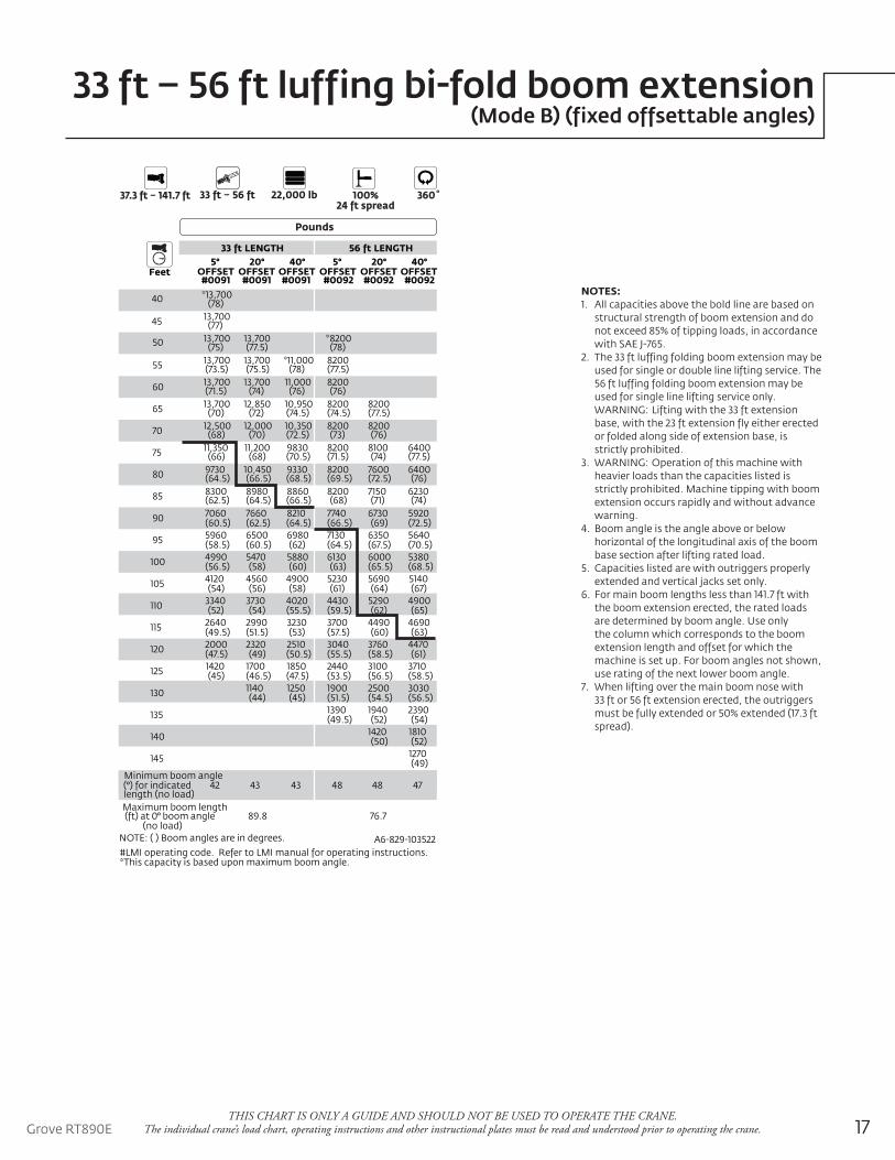
33 ft – 56 ft luffing bi-fold boom extension(Mode B) (fixed offsettable angles)
THIS CHART IS ONLY A GUIDE AND SHOULD NOT BE USED TO OPERATE THE CRANE. The individual crane’s load chart, operating instructions and other instructional plates must be read and understood prior to operating the crane.
Pounds
37.3 ft – 141.7 ft 22,000 lb33 ft – 56 ft 100%24 ft spread
360˚
Feet
33 ft LENGTH 56 ft LENGTH5° 20° 40° 5° 20° 40°
OFFSET OFFSET OFFSET OFFSET OFFSET OFFSET#0091 #0091 #0091 #0092 #0092 #0092
40 *13,700(78)
45 13,700(77)
50 13,700(75)
13,700(77.5)
*8200(78)
55 13,700(73.5)
13,700(75.5)
*11,000(78)
8200(77.5)
60 13,700(71.5)
13,700(74)
11,000(76)
8200(76)
65 13,700(70)
12,850(72)
10,950(74.5)
8200(74.5)
8200(77.5)
70 12,500(68)
12,000(70)
10,350(72.5)
8200(73)
8200(76)
75 11,350(66)
11,200(68)
9830(70.5)
8200(71.5)
8100(74)
6400(77.5)
80 9730(64.5)
10,450(66.5)
9330(68.5)
8200(69.5)
7600(72.5)
6400(76)
85 8300(62.5)
8980(64.5)
8860(66.5)
8200(68)
7150(71)
6230(74)
90 7060(60.5)
7660(62.5)
8210(64.5)
7740(66.5)
6730(69)
5920(72.5)
95 5960(58.5)
6500(60.5)
6980(62)
7130(64.5)
6350(67.5)
5640(70.5)
100 4990(56.5)
5470(58)
5880(60)
6130(63)
6000(65.5)
5380(68.5)
105 4120(54)
4560(56)
4900(58)
5230(61)
5690(64)
5140(67)
110 3340(52)
3730(54)
4020(55.5)
4430(59.5)
5290(62)
4900(65)
115 2640(49.5)
2990(51.5)
3230(53)
3700(57.5)
4490(60)
4690(63)
120 2000(47.5)
2320(49)
2510(50.5)
3040(55.5)
3760(58.5)
4470(61)
125 1420(45)
1700(46.5)
1850(47.5)
2440(53.5)
3100(56.5)
3710(58.5)
130 1140(44)
1250(45)
1900(51.5)
2500(54.5)
3030(56.5)
135 1390(49.5)
1940(52)
2390(54)
140 1420(50)
1810(52)
145 1270(49)
Minimum boom angle(°) for indicated length (no load)
42 43 43 48 48 47
Maximum boom length(ft) at 0° boom angle
(no load)89.8 76.7
NOTE: ( ) Boom angles are in degrees. A6-829-103522#LMI operating code. Refer to LMI manual for operating instructions.*This capacity is based upon maximum boom angle.
NOTES:1. All capacities above the bold line are based on
structural strength of boom extension and do not exceed 85% of tipping loads, in accordance with SAE J-765.
2. The 33 ft luffing folding boom extension may be used for single or double line lifting service. The 56 ft luffing folding boom extension may be used for single line lifting service only.
WARNING: Lifting with the 33 ft extension base, with the 23 ft extension fly either erected or folded along side of extension base, is strictly prohibited.
3. WARNING: Operation of this machine with heavier loads than the capacities listed is strictly prohibited. Machine tipping with boom extension occurs rapidly and without advance warning.
4. Boom angle is the angle above or below horizontal of the longitudinal axis of the boom base section after lifting rated load.
5. Capacities listed are with outriggers properly extended and vertical jacks set only.
6. For main boom lengths less than 141.7 ft with the boom extension erected, the rated loads are determined by boom angle. Use only the column which corresponds to the boom extension length and offset for which the machine is set up. For boom angles not shown, use rating of the next lower boom angle.
7. When lifting over the main boom nose with 33 ft or 56 ft extension erected, the outriggers must be fully extended or 50% extended (17.3 ft spread).
18
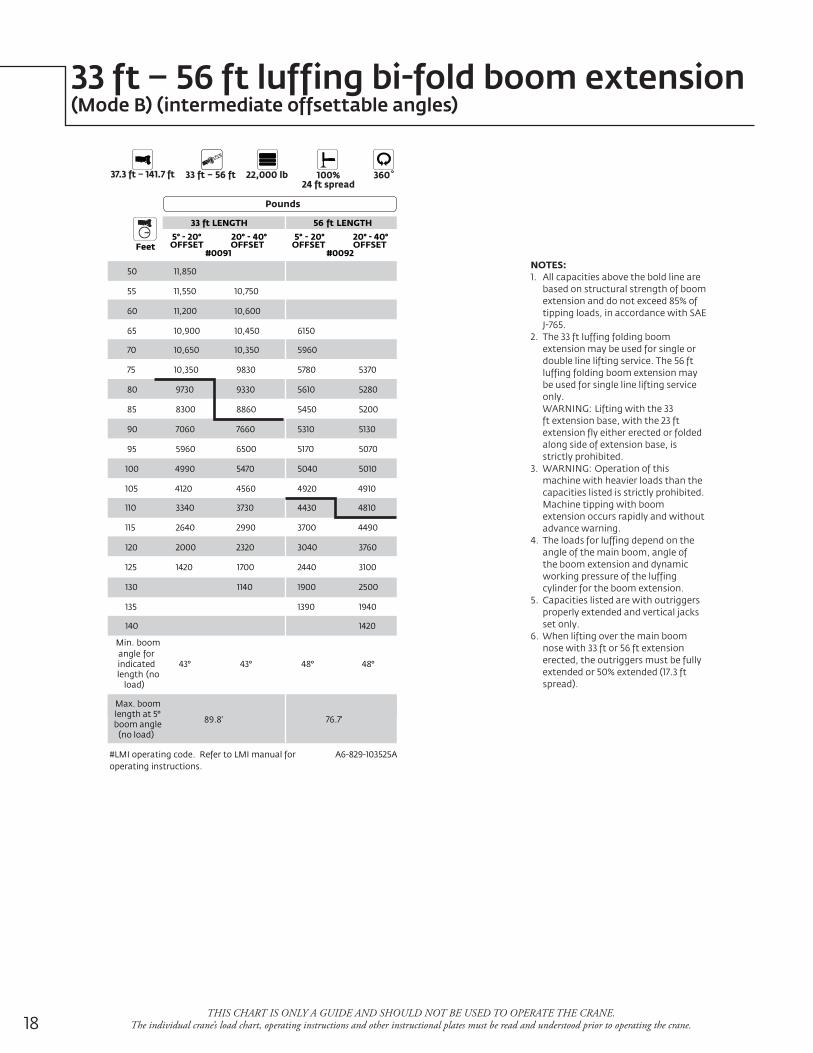
33 ft – 56 ft luffing bi-fold boom extension(Mode B) (intermediate offsettable angles)
THIS CHART IS ONLY A GUIDE AND SHOULD NOT BE USED TO OPERATE THE CRANE. The individual crane’s load chart, operating instructions and other instructional plates must be read and understood prior to operating the crane.
Pounds
37.3 ft – 141.7 ft 22,000 lb33 ft – 56 ft 100%24 ft spread
360˚
Feet
33 ft LENGTH 56 ft LENGTH
5° - 20° 20° - 40° 5° - 20° 20° - 40°OFFSET OFFSET OFFSET OFFSET
#0091 #0092
50 11,850
55 11,550 10,750
60 11,200 10,600
65 10,900 10,450 6150
70 10,650 10,350 5960
75 10,350 9830 5780 5370
80 9730 9330 5610 5280
85 8300 8860 5450 5200
90 7060 7660 5310 5130
95 5960 6500 5170 5070
100 4990 5470 5040 5010
105 4120 4560 4920 4910
110 3340 3730 4430 4810
115 2640 2990 3700 4490
120 2000 2320 3040 3760
125 1420 1700 2440 3100
130 1140 1900 2500
135 1390 1940
140 1420
Min. boomangle forindicatedlength (no
load)
43° 43° 48° 48°
Max. boomlength at 5°boom angle
(no load)
89.8' 76.7'
#LMI operating code. Refer to LMI manual foroperating instructions.
A6-829-103525A
NOTES:1. All capacities above the bold line are
based on structural strength of boom extension and do not exceed 85% of tipping loads, in accordance with SAE J-765.
2. The 33 ft luffing folding boom extension may be used for single or double line lifting service. The 56 ft luffing folding boom extension may be used for single line lifting service only.
WARNING: Lifting with the 33 ft extension base, with the 23 ft extension fly either erected or folded along side of extension base, is strictly prohibited.
3. WARNING: Operation of this machine with heavier loads than the capacities listed is strictly prohibited. Machine tipping with boom extension occurs rapidly and without advance warning.
4. The loads for luffing depend on the angle of the main boom, angle of the boom extension and dynamic working pressure of the luffing cylinder for the boom extension.
5. Capacities listed are with outriggers properly extended and vertical jacks set only.
6. When lifting over the main boom nose with 33 ft or 56 ft extension erected, the outriggers must be fully extended or 50% extended (17.3 ft spread).
19Grove RT890ETHIS CHART IS ONLY A GUIDE AND SHOULD NOT BE USED TO OPERATE THE CRANE.
The individual crane’s load chart, operating instructions and other instructional plates must be read and understood prior to operating the crane.
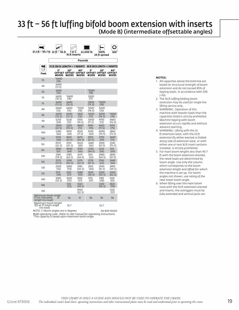
Pounds
37.3 ft – 141.7 ft 1 or 2 16 ft inserts
22,000 lb33 ft – 56 ft 100%24 ft spread
360˚
Feet
72 ft (56 ft LENGTH + 1 INSERT) 88 ft (56 ft LENGTH + 2 INSERTS)
5° 20° 40° 5° 20° 40°OFFSET OFFSET OFFSET OFFSET OFFSET OFFSET#0095 #0095 #0095 #1095 #1095 #1095
55 *6400(78)
60 6400(77.5)
65 6400(76)
*5000(78)
70 6400(74.5)
*6400(78)
5000(77)
75 6400(73.5)
6400(76.5)
5000(75.5)
*5000(78)
80 6400(72)
6400(75)
*5500(78)
5000(74.5)
5000(76)
85 6400(70.5)
6040(73.5)
5420(76)
5000(73)
5000(74.5)
*4460(78)
90 6250(69)
5630(72)
5100(74.5)
5000(71.5)
4790(73)
4460(76.5)
95 5800(67.5)
5260(70.5)
4800(73)
4740(70)
4420(71.5)
4150(75)
100 5380(66)
4910(69)
4520(71.5)
4350(69)
4090(70.5)
3860(73.5)
105 5010(64)
4610(67.5)
4270(69.5)
4010(67.5)
3790(69)
3600(72)
110 4570(62.5)
4310(65.5)
4020(68)
3680(66)
3490(67.5)
3340(70.5)
115 3840(61)
4040(64)
3790(66)
3390(64.5)
3230(66)
3110(69)
120 3180(59.5)
3780(62.5)
3570(64.5)
3110(63)
2980(64.5)
2890(67.5)
125 2570(57.5)
3290(60.5)
3370(62.5)
2720(61.5)
2760(63)
2680(66)
130 2020(56)
2680(59)
3180(60.5)
2160(60)
2540(61.5)
2480(64.5)
135 1510(54)
2120(57)
2680(59)
1640(58.5)
2300(59.5)
2300(62.5)
140 1040(52.5)
1600(55)
2100(57)
1170(57)
1780(58)
2120(61)
145 1130(53)
1560(54.5)
1300(56.5)
1820(59)
150 1060(52.5)
1320(57)
Minimum boom angle(°) for indicated length (no load)
51 52 51 56 55 56
Maximum boom length(ft) at 0° boom angle
(no load)76.7 63.7
NOTE: ( ) Boom angles are in degrees. A6-829-103523#LMI operating code. Refer to LMI manual for operating instructions.*This capacity is based upon maximum boom angle.
NOTES:1. All capacities above the bold line are
based on structural strength of boom extension and do not exceed 85% of tipping loads, in accordance with SAE J-765.
2. The 56 ft luffing folding boom extension may be used for single line lifting service only.
3. WARNING: Operation of this machine with heavier loads than the capacities listed is strictly prohibited. Machine tipping with boom extension occurs rapidly and without advance warning.
4. WARNING: Lifting with the 33 ft extension base, with the 23 ft extension fly either erected or folded along side of extension base, or with either one or two 16 ft insert sections installed, is strictly prohibited.
5. For main boom lengths less than 141.7 ft with the boom extension erected, the rated loads are determined by boom angle. Use only the column which corresponds to the boom extension length and offset for which the machine is set up. For boom angles not shown, use rating of the next lower boom angle.
6. When lifting over the main boom nose with the 56 ft extension erected and inserts, the outriggers must be fully extended and vertical jacks set.
33 ft – 56 ft luffing bifold boom extension with inserts(Mode B) (intermediate offsettable angles)
20
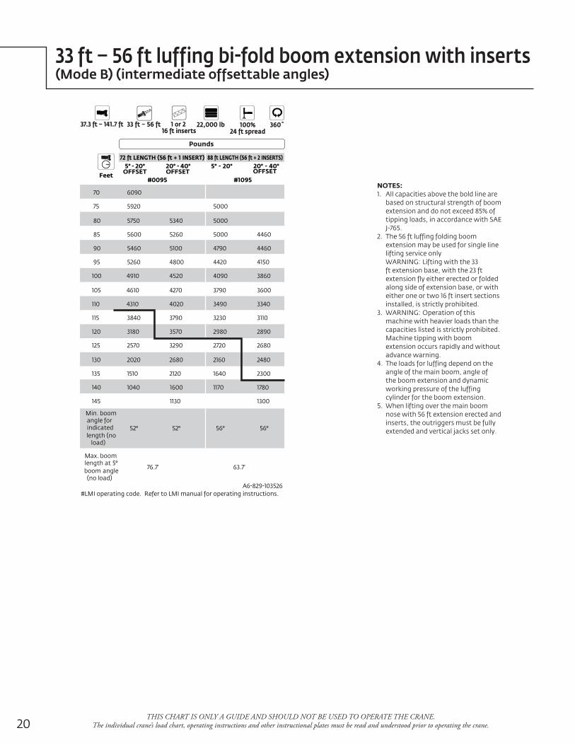
33 ft – 56 ft luffing bi-fold boom extension with inserts(Mode B) (intermediate offsettable angles)
THIS CHART IS ONLY A GUIDE AND SHOULD NOT BE USED TO OPERATE THE CRANE. The individual crane’s load chart, operating instructions and other instructional plates must be read and understood prior to operating the crane.
Feet
72 ft LENGTH (56 ft + 1 INSERT) 88 ft LENGTH (56 ft + 2 INSERTS)5° - 20°
OFFSET20° - 40°OFFSET
5° - 20° 20° - 40°OFFSET
#0095 #1095
70 6090
75 5920 5000
80 5750 5340 5000
85 5600 5260 5000 4460
90 5460 5100 4790 4460
95 5260 4800 4420 4150
100 4910 4520 4090 3860
105 4610 4270 3790 3600
110 4310 4020 3490 3340
115 3840 3790 3230 3110
120 3180 3570 2980 2890
125 2570 3290 2720 2680
130 2020 2680 2160 2480
135 1510 2120 1640 2300
140 1040 1600 1170 1780
145 1130 1300
Min. boomangle forindicatedlength (no
load)
52° 52° 56° 56°
Max. boomlength at 5°boom angle
(no load)
76.7' 63.7'
#LMI operating code. Refer to LMI manual for operating instructions.A6-829-103526
Pounds
37.3 ft – 141.7 ft 1 or 2 16 ft inserts
22,000 lb33 ft – 56 ft 100%24 ft spread
360˚
NOTES:1. All capacities above the bold line are
based on structural strength of boom extension and do not exceed 85% of tipping loads, in accordance with SAE J-765.
2. The 56 ft luffing folding boom extension may be used for single line lifting service only
WARNING: Lifting with the 33 ft extension base, with the 23 ft extension fly either erected or folded along side of extension base, or with either one or two 16 ft insert sections installed, is strictly prohibited.
3. WARNING: Operation of this machine with heavier loads than the capacities listed is strictly prohibited. Machine tipping with boom extension occurs rapidly and without advance warning.
4. The loads for luffing depend on the angle of the main boom, angle of the boom extension and dynamic working pressure of the luffing cylinder for the boom extension.
5. When lifting over the main boom nose with 56 ft extension erected and inserts, the outriggers must be fully extended and vertical jacks set only.
21Grove RT890ETHIS CHART IS ONLY A GUIDE AND SHOULD NOT BE USED TO OPERATE THE CRANE.
The individual crane’s load chart, operating instructions and other instructional plates must be read and understood prior to operating the crane.
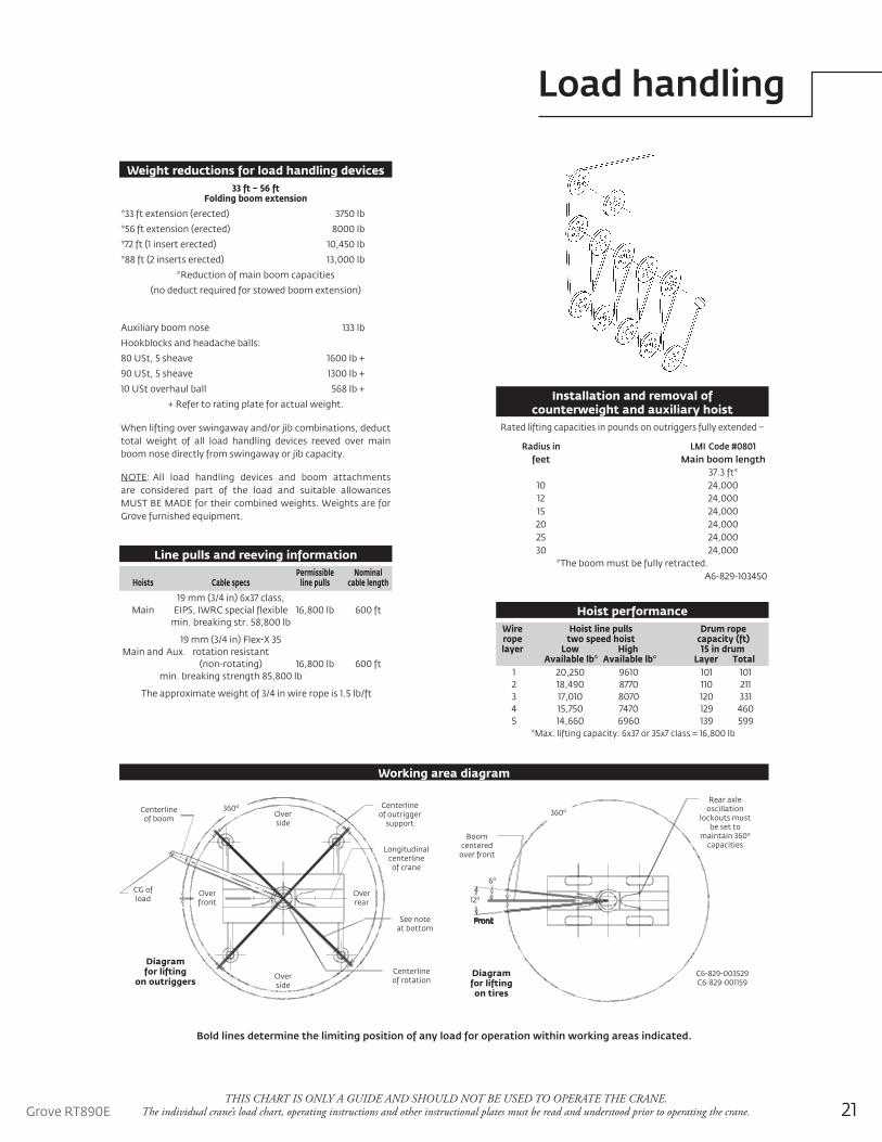
Load handling
Installation and removal of counterweight and auxiliary hoist
Rear axleoscillation
lockouts mustbe set to
maintain 360o
capacitiesBoom
centeredover front
Diagramfor liftingon tires
C6-829-003529C6-829-001159
Front
360o
12o
6o
Centerlineof boom
Diagramfor lifting
on outriggers
Centerlineof outrigger
support
Longitudinalcenterline
of crane
See noteat bottom
Centerlineof rotation
CG ofload
Overfront
Overrear
Overside
Overside
360o
Working area diagram
Bold lines determine the limiting position of any load for operation within working areas indicated.
When lifting over swingaway and/or jib combinations, deduct total weight of all load handling devices reeved over main boom nose directly from swingaway or jib capacity.
NOTE: All load handling devices and boom attachments are considered part of the load and suitable allowances MUST BE MADE for their combined weights. Weights are for Grove furnished equipment.
Weight reductions for load handling devices
Wire Hoist line pulls Drum rope rope two speed hoist capacity (ft) layer Low High 15 in drum Available lb* Available lb* Layer Total 1 20,250 9610 101 101 2 18,490 8770 110 211 3 17,010 8070 120 331 4 15,750 7470 129 460 5 14,660 6960 139 599
*Max. lifting capacity: 6x37 or 35x7 class = 16,800 lb
Hoist performance
Permissible Nominal Hoists Cable specs line pulls cable length
19 mm (3/4 in) 6x37 class, Main EIPS, IWRC special flexible 16,800 lb 600 ft min. breaking str. 58,800 lb
19 mm (3/4 in) Flex-X 35 Main and Aux. rotation resistant (non-rotating) 16,800 lb 600 ft min. breaking strength 85,800 lb
The approximate weight of 3/4 in wire rope is 1.5 lb/ft
33 ft – 56 ftFolding boom extension
*33 ft extension (erected) 3750 lb
*56 ft extension (erected) 8000 lb
*72 ft (1 insert erected) 10,450 lb
*88 ft (2 inserts erected) 13,000 lb
*Reduction of main boom capacities
(no deduct required for stowed boom extension)
Rated lifting capacities in pounds on outriggers fully extended –
Radius in LMI Code #0801 feet Main boom length 37.3 ft* 10 24,000 12 24,000 15 24,000 20 24,000 25 24,000 30 24,000
*The boom must be fully retracted.A6-829-103450
Auxiliary boom nose 133 lb
Hookblocks and headache balls:
80 USt, 5 sheave 1600 lb +
90 USt, 5 sheave 1300 lb +
10 USt overhaul ball 568 lb +
+ Refer to rating plate for actual weight.
Line pulls and reeving information

22
Notes

23Grove RT890E
Notes

©2011 ManitowocPrinted in USAForm No. RT890E PGPart No. 04-008 - 2M -1211 www.manitowoc.com
This document is non-contractual. Constant improvement and engineering progress make it necessary that we reserve the right to make specification, equipment, and price changes without notice. Illustrations shown may include optional equipment and accessories and may not include all standard equipment.
Regional offices
ChinaShanghai, China Tel: +86 21 6457 0066Fax: +86 21 6457 4955
Greater Asia-Pacific Singapore Tel: +65 6264 1188 Fax: +65 6862 4040
Europe, Middle East, Africa Ecully, France Tel: +33 (0)4 72 18 20 20 Fax: +33 (0)4 72 18 20 00
Americas Manitowoc, Wisconsin, USA Tel: +1 920 684 6621 Fax: +1 920 683 6277
Shady Grove, Pennsylvania, USA Tel: +1 717 597 8121 Fax: +1 717 597 4062
Regional headquarters
Manitowoc Cranes
ChinaBeijingChengduGuangzhouXian
Greater Asia-PacificAustraliaAdelaideBrisbaneMelbourneSydneyIndiaCalcuttaChennaiDelhiHyderabadPuneKoreaSeoulPhilippinesMakati CitySingapore
FactoriesBrazilAlphavilleChinaTaiAnZhangjiagangFranceCharlieuMoulinsGermanyWilhelmshavenIndiaPuneItalyNiella TanaroPortugalBaltarFânzeresSlovakiaSarisUSAManitowoc Port WashingtonShady Grove
AmericasBrazilAlphavilleMexicoMonterreyChileSantiago
Europe, Middle East, AfricaCzech RepublicNetvoriceFranceBaudemontCergyDecinesGermanyLangenfeldHungaryBudapestItalyLainateNetherlandsBredaPolandWarsawPortugalBaltarRussiaMoscowU.A.E.DubaiU.K.Buckingham