grove - starter kit v1.0b what is new in grove starter kit v1 · grove - starter kit v1.0b ... one...
TRANSCRIPT
GROVE - Starter Kit V1.0b
Introduction
The Grove system is a modular, safe and easy to use group of items that allow you to minimise the effort
required to get started with microcontroller-based experimentation and learning. Although there are
many choices available for microcontroller development environments, the Grove system will work very
well with the Arduino system.
What is new in Grove Starter Kit v1.0b:
Upgrade 8 x 2 character LCD display kit to 16 x 2 character LCD display kit with Serial LCD Driver.
Simplify Twin-LED Grove to Single LED Grove for wiring simplicity, the Twin-Button Grove has
also been changed to a One Button Grove module.
Removed the unnecessary edge mounting of the Grove units (except the Protoshield module).
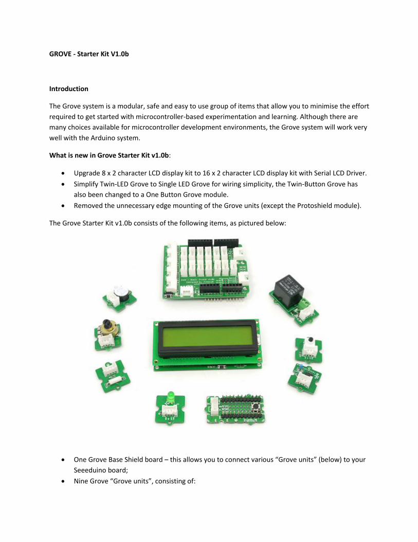
The Grove Starter Kit v1.0b consists of the following items, as pictured below:
One Grove Base Shield board – this allows you to connect various “Grove units” (below) to your
Seeeduino board;
Nine Grove “Grove units”, consisting of:
16 x 2 character LCD display unit and matching Grove;
Analog temperature sensor Grove;
Piezo buzzer Grove;
Button Grove (with one buttons for digital input);
LED Grove (with one green for digital output);
Tilt switch Grove;
Potentiometer (variable resistor of value 10k ohms) for analog input
Relay Grove
Protoshield Grove (for adding your own components)
Ten pre-formed connecting wires to bridge Grove units to the Grove - Base Shield board (not
shown)
Now let's look at each component in more detail.
Grove - Base Shield
First we start with the Grove base shield board. Grove - Base Shield is the new version of Electronic Brick
Shield.The Basic Shield is compatible with Seeeduino v2.21 (168p and 328p), and Arduino UNO and
Duemilanove. We standardize all the connectors into 4 pins(Signal 1,Signal 2,VCC and GND) 2mm
connectors, which simplify the wiring of electronics projects. The 4pins buckled connectors also make
the wiring a snap. We built many different kinds of Grove to match up with Base Shield, and if you have
existing Electronic Brick modules, you don't have to worry about compatibility--we have various
converter cables that address compatibility between these two systems. This is very similar to an
Arduino shield, and of course, can be used with our Seeeduino or Mega board, as well as other Arduino-
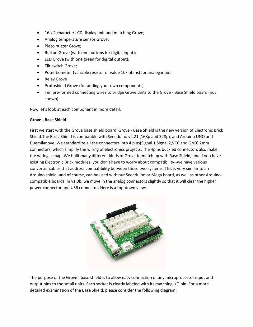
compatible boards. In v1.0b, we move in the analog connectors slightly so that it will clear the higher
power connector and USB connector. Here is a top-down view:
The purpose of the Grove - base shield is to allow easy connection of any microprocessor input and
output pins to the small units. Each socket is clearly labeled with its matching I/O pin. For a more
detailed examination of the Base Shield, please consider the following diagram:
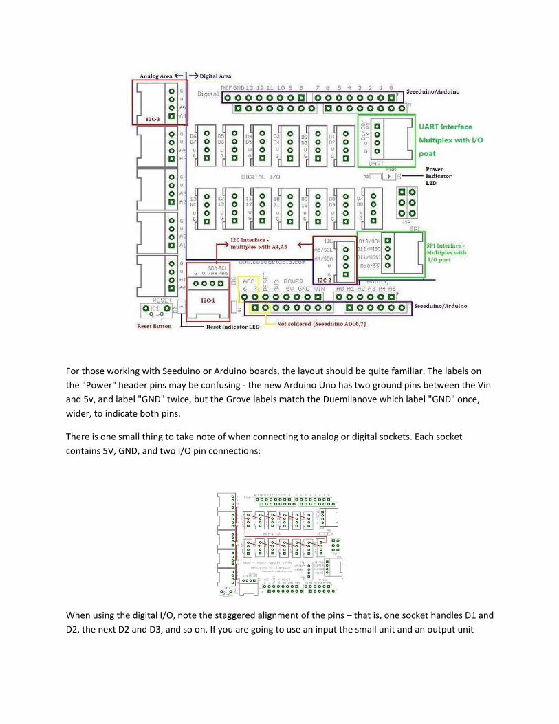
For those working with Seeduino or Arduino boards, the layout should be quite familiar. The labels on
the "Power" header pins may be confusing - the new Arduino Uno has two ground pins between the Vin
and 5v, and label "GND" twice, but the Grove labels match the Duemilanove which label "GND" once,
wider, to indicate both pins.
There is one small thing to take note of when connecting to analog or digital sockets. Each socket
contains 5V, GND, and two I/O pin connections:
When using the digital I/O, note the staggered alignment of the pins – that is, one socket handles D1 and
D2, the next D2 and D3, and so on. If you are going to use an input the small unit and an output unit
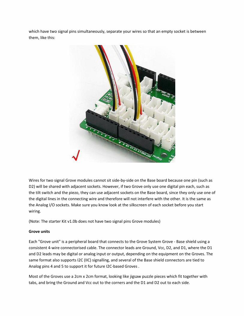
which have two signal pins simultaneously, separate your wires so that an empty socket is between
them, like this:
Wires for two signal Grove modules cannot sit side-by-side on the Base board because one pin (such as
D2) will be shared with adjacent sockets. However, if two Grove only use one digital pin each, such as
the tilt switch and the piezo, they can use adjacent sockets on the Base board, since they only use one of
the digital lines in the connecting wire and therefore will not interfere with the other. It is the same as
the Analog I/O sockets. Make sure you know look at the silkscreen of each socket before you start
wiring.
(Note: The starter Kit v1.0b does not have two signal pins Grove modules)
Grove units
Each "Grove unit" is a peripheral board that connects to the Grove System Grove - Base shield using a
consistent 4-wire connectorised cable. The connector leads are Ground, Vcc, D2, and D1, where the D1
and D2 leads may be digital or analog input or output, depending on the equipment on the Groves. The
same format also supports I2C (IIC) signalling, and several of the Base shield connectors are tied to
Analog pins 4 and 5 to support it for future I2C-based Groves .
Most of the Groves use a 2cm x 2cm format, looking like jigsaw puzzle pieces which fit together with
tabs, and bring the Ground and Vcc out to the corners and the D1 and D2 out to each side.
(Request for description from the designer - the pieces don't actually snap together, so I can't tell if
there's any way to use the connectors on the edges. Are they meant to connect to header pins on a
metric-spaced breadboard? Are they meant to connect I2C Grove units together, or are there other
reasons to connect non-I2C Grove units like that?)
A circuit diagram would look really nice here.
Next, let's examine each of our “Grove units”, and then use each on in an example Arduino sketch that
we can use with our Seeeduino boards...
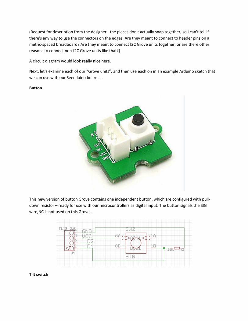
Button
This new version of button Grove contains one independent button, which are configured with pull-
down resistor – ready for use with our microcontrollers as digital input. The button signals the SIG
wire,NC is not used on this Grove .
Tilt switch
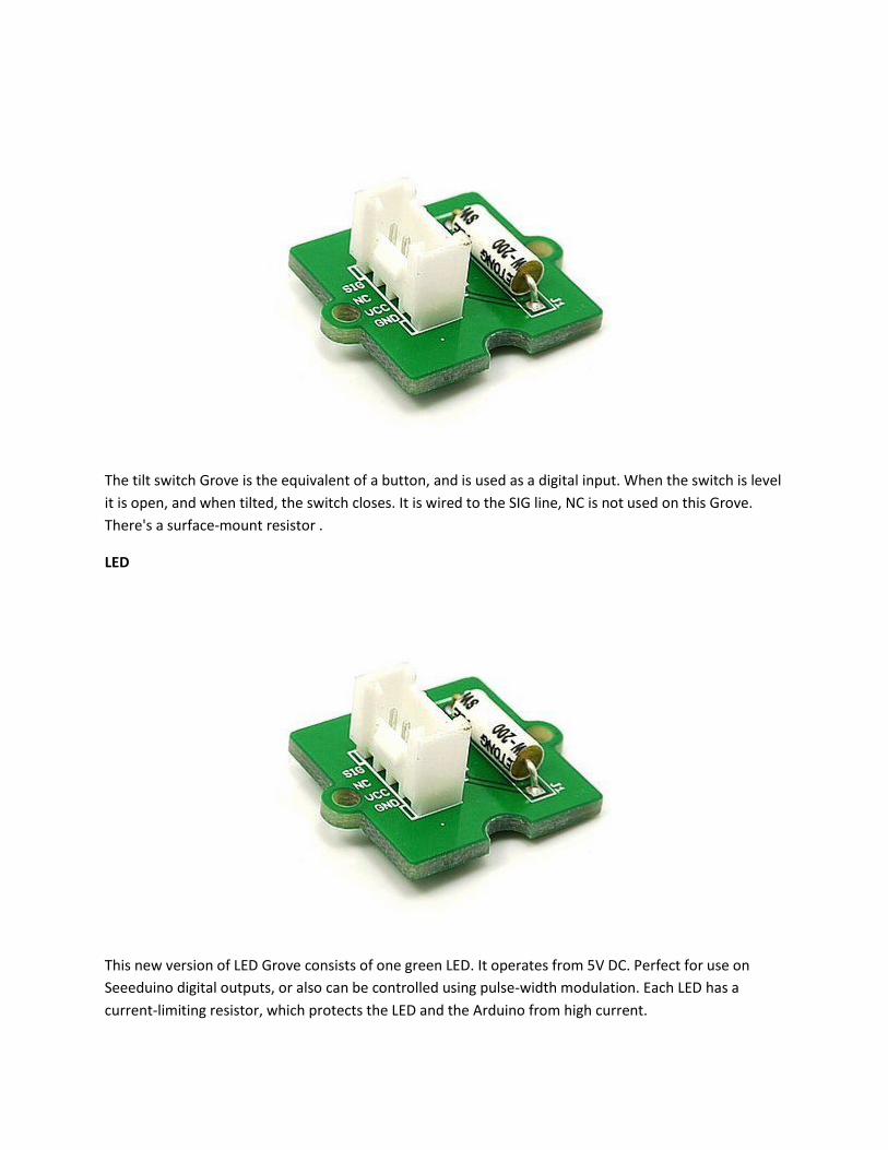
The tilt switch Grove is the equivalent of a button, and is used as a digital input. When the switch is level
it is open, and when tilted, the switch closes. It is wired to the SIG line, NC is not used on this Grove.
There's a surface-mount resistor .
LED
This new version of LED Grove consists of one green LED. It operates from 5V DC. Perfect for use on
Seeeduino digital outputs, or also can be controlled using pulse-width modulation. Each LED has a
current-limiting resistor, which protects the LED and the Arduino from high current.
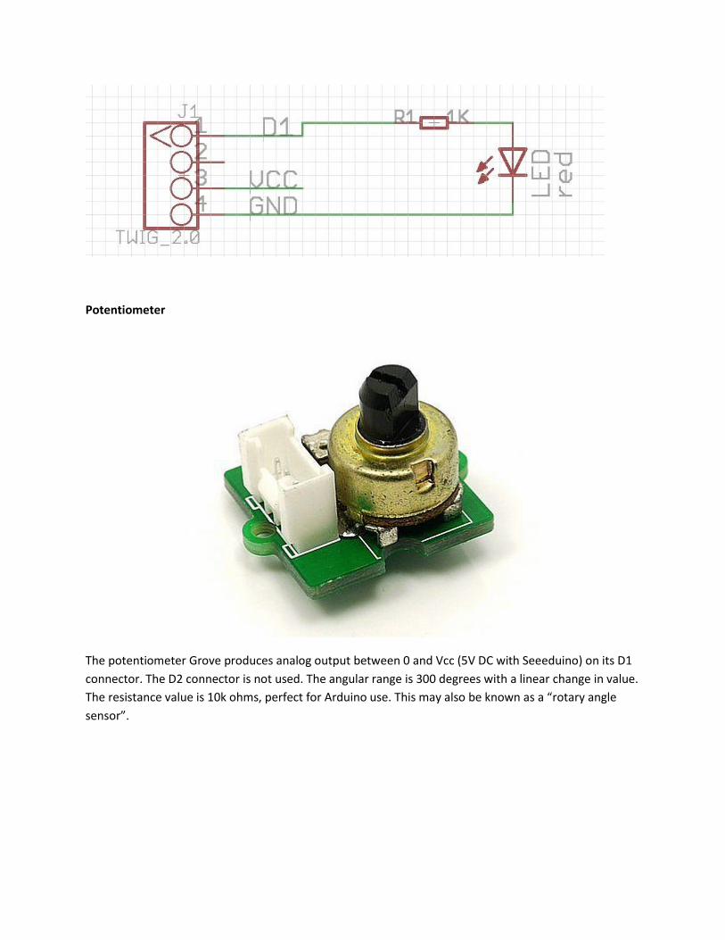
Potentiometer
The potentiometer Grove produces analog output between 0 and Vcc (5V DC with Seeeduino) on its D1
connector. The D2 connector is not used. The angular range is 300 degrees with a linear change in value.
The resistance value is 10k ohms, perfect for Arduino use. This may also be known as a “rotary angle
sensor”.
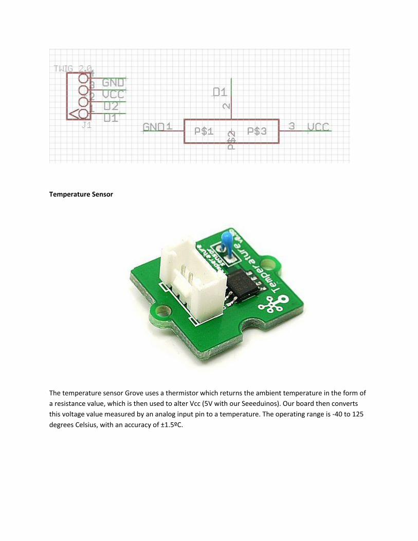
Temperature Sensor
The temperature sensor Grove uses a thermistor which returns the ambient temperature in the form of
a resistance value, which is then used to alter Vcc (5V with our Seeeduinos). Our board then converts
this voltage value measured by an analog input pin to a temperature. The operating range is -40 to 125
degrees Celsius, with an accuracy of ±1.5ºC.
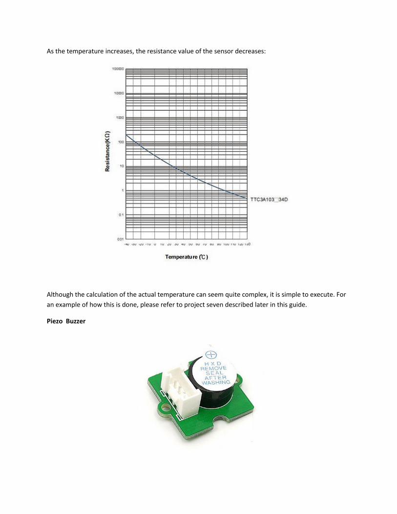
As the temperature increases, the resistance value of the sensor decreases:
Although the calculation of the actual temperature can seem quite complex, it is simple to execute. For
an example of how this is done, please refer to project seven described later in this guide.
Piezo Buzzer
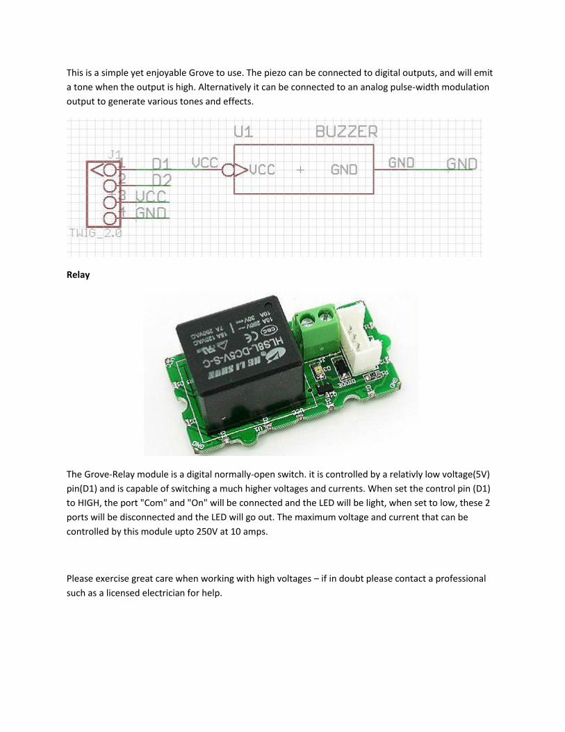
This is a simple yet enjoyable Grove to use. The piezo can be connected to digital outputs, and will emit
a tone when the output is high. Alternatively it can be connected to an analog pulse-width modulation
output to generate various tones and effects.
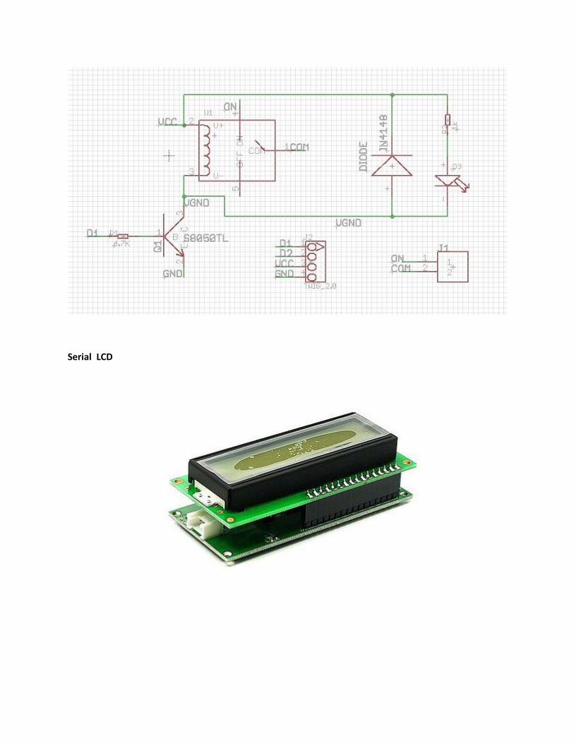
Relay
The Grove-Relay module is a digital normally-open switch. it is controlled by a relativly low voltage(5V)
pin(D1) and is capable of switching a much higher voltages and currents. When set the control pin (D1)
to HIGH, the port "Com" and "On" will be connected and the LED will be light, when set to low, these 2
ports will be disconnected and the LED will go out. The maximum voltage and current that can be
controlled by this module upto 250V at 10 amps.
Please exercise great care when working with high voltages – if in doubt please contact a professional
such as a licensed electrician for help.
Serial LCD
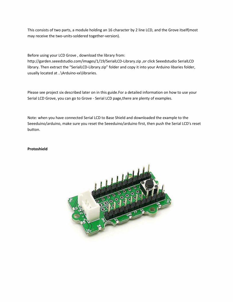
This consists of two parts, a module holding an 16 character by 2 line LCD, and the Grove itself(most
may receive the two-units-soldered together-version).
Before using your LCD Grove , download the library from:
http://garden.seeedstudio.com/images/1/19/SerialLCD-Library.zip ,or click Seeedstudio SerialLCD
library. Then extract the “SerialLCD-Library.zip” folder and copy it into your Arduino libaries folder,
usually located at ..\Arduino-xx\libraries.
Please see project six described later on in this guide.For a detailed information on how to use your
Serial LCD Grove, you can go to Grove - Serial LCD page,there are plenty of examples.
Note: when you have connected Serial LCD to Base Shield and downloaded the example to the
Seeeduino/arduino, make sure you reset the Seeeduino/arduino first, then push the Serial LCD's reset
button.
Protoshield

This Grove allows you to add your own circuitry or components to your Grove system prototypes. This
allows you access to all four lines from the connector cable – S0, S1, VCC and GND. There is also an extra
normally-open button to take advantage of. The hole spacing makes using normal DIP-format ICs and
other components very simple. You may wish to purchase more for future use in advance.
Features
Standardized – scalable Jigsaw shape, unified 4 pin connector, screw hole grid, edge solder pad,
reduce duplicate developing, reuse in different projects to reduce environment impact
Compact – size from 2cm*2 cm, seamless combination, surface mounting components, 2.0mm
pitch cable
Friendly – easy buckled connection, dumb proof, various extension modes, open for DIY,
libraries and demo codes
Plentiful- large selection of common circuits from basic (button, LED) to professional sensor
(Gyro, Compass), keep adding per demand, 3rd party contributions, reusable
Community based – satisfying needs through voting, democratized design, project and recipe
sharing, profit sharing business pattern, Renting and Reuse
Application Ideas
Application1
Application2
Application3
Cautions
The warnings and wrong operations possible cause dangerous.
Schematic
It is the schematic, the circuit about Eagle resource like .pdf should linked here in order to avoid
memory exhausted.
Specification
May include key specification and other specifications.
Pin definition and Rating
Mechanic Dimensions
Usage
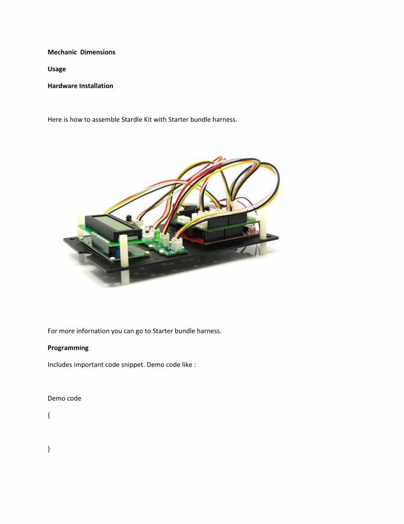
Hardware Installation
Here is how to assemble Stardle Kit with Starter bundle harness.
For more infornation you can go to Starter bundle harness.
Programming
Includes important code snippet. Demo code like :
Demo code
{
}
Example
Now you should be familiar with your Base Shield and Grove units, so let's examine them in more detail
with the following projects:
Project One - Blink
Project Two - Digital Input v1.0b
Project Three – Analog Input v1.0b
Project Four – Noise Maker
Project Five – Relay Control
Project Six – LCD Demonstration
Project Seven - Temperature
Project Eight - Thermostat
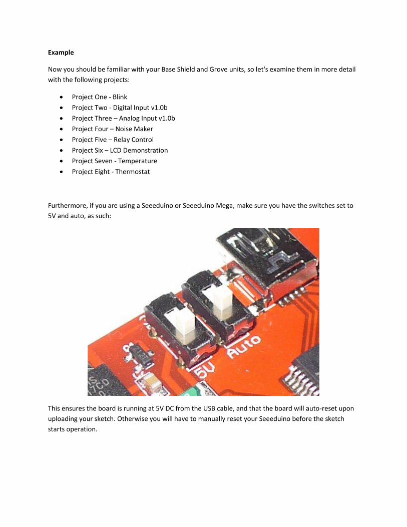
Furthermore, if you are using a Seeeduino or Seeeduino Mega, make sure you have the switches set to
5V and auto, as such:
This ensures the board is running at 5V DC from the USB cable, and that the board will auto-reset upon
uploading your sketch. Otherwise you will have to manually reset your Seeeduino before the sketch
starts operation.