grs-6052a/6032a oscilloscope declaration of … · time 50 or 30mhz analog oscilloscope and become...
TRANSCRIPT
i
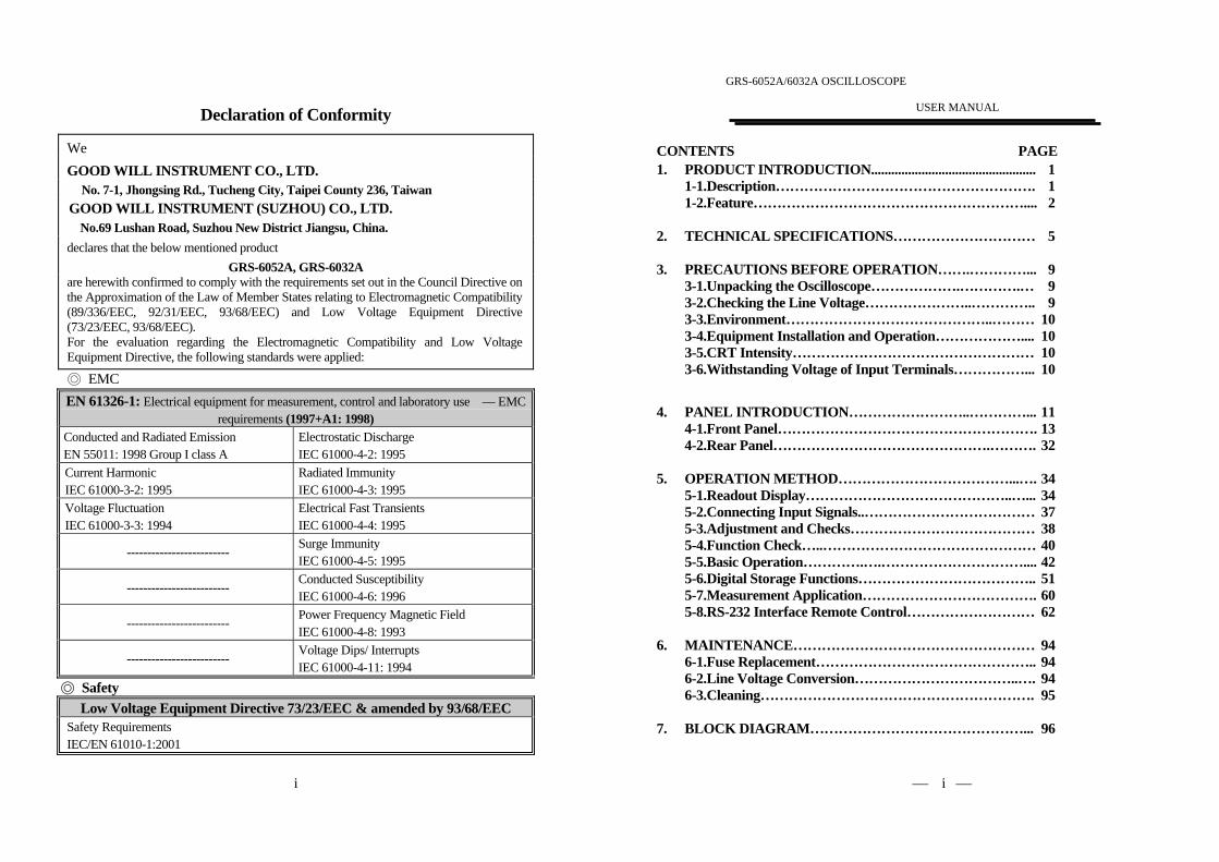
Declaration of Conformity
WeGOOD WILL INSTRUMENT CO., LTD.
No. 7-1, Jhongsing Rd., Tucheng City, Taipei County 236, TaiwanGOOD WILL INSTRUMENT (SUZHOU) CO., LTD.
No.69 Lushan Road, Suzhou New District Jiangsu, China.declares that the below mentioned product
GRS-6052A, GRS-6032Aare herewith confirmed to comply with the requirements set out in the Council Directive onthe Approximation of the Law of Member States relating to Electromagnetic Compatibility(89/336/EEC, 92/31/EEC, 93/68/EEC) and Low Voltage Equipment Directive(73/23/EEC, 93/68/EEC).For the evaluation regarding the Electromagnetic Compatibility and Low VoltageEquipment Directive, the following standards were applied:
◎ EMCEN 61326-1: Electrical equipment for measurement, control and laboratory use –– EMC
requirements (1997+A1: 1998)Conducted and Radiated EmissionEN 55011: 1998 Group I class A
Electrostatic DischargeIEC 61000-4-2: 1995
Current HarmonicIEC 61000-3-2: 1995
Radiated ImmunityIEC 61000-4-3: 1995
Voltage FluctuationIEC 61000-3-3: 1994
Electrical Fast TransientsIEC 61000-4-4: 1995
-------------------------Surge ImmunityIEC 61000-4-5: 1995
-------------------------Conducted SusceptibilityIEC 61000-4-6: 1996
-------------------------Power Frequency Magnetic FieldIEC 61000-4-8: 1993
-------------------------Voltage Dips/ InterruptsIEC 61000-4-11: 1994
◎ SafetyLow Voltage Equipment Directive 73/23/EEC & amended by 93/68/EEC
Safety RequirementsIEC/EN 61010-1:2001
GRS-6052A/6032A OSCILLOSCOPE
USER MANUAL
⎯ ⎯i
CONTENTS PAGE1. PRODUCT INTRODUCTION.................................................
1-1.Description……………………………………………….1-2.Feature…………………………………………………....
1 1 2
2. TECHNICAL SPECIFICATIONS………………………… 5
3. PRECAUTIONS BEFORE OPERATION…….…………...3-1.Unpacking the Oscilloscope……………….………….…3-2.Checking the Line Voltage…………………..…………..3-3.Environment……………………………………..………3-4.Equipment Installation and Operation………………....3-5.CRT Intensity……………………………………………3-6.Withstanding Voltage of Input Terminals……………...
9 9 910101010
4. PANEL INTRODUCTION……………………..…………...4-1.Front Panel……………………………………………….4-2.Rear Panel……………………………………….……….
111332
5. OPERATION METHOD………………………………...….5-1.Readout Display……………………………………..…...5-2.Connecting Input Signals..………………………………5-3.Adjustment and Checks…………………………………5-4.Function Check…..………………………………………5-5.Basic Operation………….….…………………………....5-6.Digital Storage Functions………………………………..5-7.Measurement Application……………………………….5-8.RS-232 Interface Remote Control………………………
343437384042516062
6. MAINTENANCE……………………………………………6-1.Fuse Replacement………………………………………..6-2.Line Voltage Conversion……………………………..….6-3.Cleaning………………………………………………….
94949495
7. BLOCK DIAGRAM………………………………………... 96

GRS-6052A/6032A OSCILLOSCOPE
USER MANUAL
⎯ ⎯ii
SAFETY TERMS AND SYMBOLSThese terms may appear in this manual or on the product:
WARNING. Warning statements identify condition or practicesthat could result in injury or loss of life.
CAUTION. Caution statements identify conditions or practices thatcould result in damage to this product or other property.
Measurement category I is for measurements performed on circuits not directlyconnected to MAINS.Measurement category II is for measurements performed on circuits directlyconnected to the low voltage installation.Measurement category III is for measurements performed in the buildinginstallation.Measurement category IV is for measurements performed at the source of thelow-voltage installation.
The following symbols may appear in this manual or on the product:
DANGER ATTENTION Protective Earth(ground)High Voltage refer to Manual Conductor Terminal
Terminal
GRS-6052A/6032A OSCILLOSCOPE
USER MANUAL
⎯ ⎯iii
FOR UNITED KINGDOM ONLY
NOTE: This lead/appliance must only be wired by competent persons
WARNING: THIS APPLIANCE MUST BE EARTHED
IMPORTANT: The wires in this lead are coloured in accordance with the
following code:
Green/ Yellow: EarthBlue: NeutralBrown: Live (Phase)
As the colours of the wires in main leads may not correspond with thecolours marking identified in your plug/appliance, proceed as follows:
The wire which is coloured Green & Yellow must be connected to the Earth
terminal marked with the letter E or by the earth symbol or coloured
Green or Green & Yellow.
The wire which is coloured Blue must be connected to the terminal which ismarked with the letter N or coloured Blue or Black.
The wire which is coloured Brown must be connected to the terminalmarked with the letter L or P or coloured Brown or Red.
If in doubt, consult the instructions provided with the equipment or contactthe supplier.
GRS-6052A/6032A OSCILLOSCOPE
USER MANUAL
⎯ ⎯iv
This cable/appliance should be protected by a suitably rated and approvedHBC mains fuse: refer to the rating information on the equipment and/oruser instructions for details. As a guide, cable of 0.75mm2 should beprotected by a 3A or 5A fuse. Larger conductors would normally require13A types, depending on the connection method used.
Any moulded mains connector that requires removal /replacement must bedestroyed by removal of any fuse & fuse carrier and disposed of immediately,as a plug with bared wires is hazardous if a engaged in live socket. Any re-wiring must be carried out in accordance with the information detailed onthis label.
GRS-6052A/6032A OSCILLOSCOPE
USER MANUAL
⎯ ⎯1
1.PRODUCT INTRODUCTION
1-1. Description
The GRS-6052A and GRS-6032A set a standard in performance and economy,
each equips with two professional scopes in one. They can be operated as a realtime 50 or 30MHz analog oscilloscope and become a full function digital storageoscilloscope by pressing a button. Now, you have the power for digital capture and
analysis of elusive single shots with a full 100MS/s sample rate. The instruments
provide with a high speed A/D converter for each channel to enable themeasurement, memory, and analysis of high-speed phenomena. A microprocessor-
based operating system controls most of the functions of the instrument, includingcursor readout and digitized panel setting. On-screen alphanumeric readout and
cursor function for voltage, time and frequency measurement provide extraordinary
operational convenience. Ten different user defined instrument settings can be
saved and recalled without restriction.
The vertical deflection system has two input channels. Each channel has 14 basicdeflection factors from 1mV to 20V per division. The horizontal deflection systemprovides sweep time from 100s to 0.2μs per division. The trigger system provides
stable triggering over the full bandwidth of the vertical deflection system.

GRS-6052A/6032A OSCILLOSCOPE
USER MANUAL
⎯ ⎯2
1-2.FeaturesAdditionally, the oscilloscope offers several other features:1) High intensity and internal graticule CRT
The oscilloscope employs a high intensity 6-inch rectangular type cathode-
ray tube with red internal graticule. It displays clear readable traces even athigh sweep speeds. Internal graticule lines eliminate parallax-viewing errorbetween the trace and the graticule line.
2) Multiple Digital Storage Functions
Digitizing repetitive waveform up to full bandwidth 50/30MHz throughthe use of equivalent sampling (500MS/s).
2k-word acquisition memory per channel up to 10 sets SAVE/RECALLreference memories (with back-up) are provided.
Pre-trigger function for observing waveforms before triggering. The
trigger point can be selected from 0~10 DIV (in 0.02DIV steps).
Roll mode is ideal for observing flickering low-speed signals. The
TIME/DIV range up to 100s.
The peak detect mode can detect glitch with pulse duration of 25ns ormore.
The persistence mode makes for easy measurements of jitter, voltage
variation, and etc.
The averaging function can be selected freely from 2 to 256. This
effectively reduces noise from repetitive signals.
The smoothing (dot-join) function provides linear connections betweenthe captured point, ensuring that digitized signals are displayed without
gaps.
In the magnification mode, the DOT or LINEAR interpolation can be
selected according to the waveform.
GRS-6052A/6032A OSCILLOSCOPE
USER MANUAL
⎯ ⎯3
The built-in RS-232C interface enables remote control operation andsignal processing via a PC.
The X-Y mode is same as the real time mode. The X (horizontal) signal is
connected to the input of CH1, the Y (vertical) signal is applied to theinput of CH2, and the storage waveform bandwidth up to 50MHz/30MHz.
3) ALT-MAG Function (both Real Time Mode and Storage Mode)
The primary sweep waveform along with the magnified sweep waveform can
be displayed simultaneously using the ALT-MAG function. Themagnification ratio can be selected from among three stages of ×5, ×10,
×20 for magnifying the displayed waveform in the center of the CRT.
4) Convenient VERT-MODE Triggering
The sync signal source is decided automatically when vertical axis mode is
switched. This means that you need not change the trigger source every time
you switch the VERT-MODE.
5) TV triggering
Exclusive TV sync separator circuit technology provides stable TV signalmeasurements on fields, frames and lines.
6) Hold Off (Real Time Mode only)
The function allows the obtaining of stable synchronization for even
complex waveforms that are difficult to synchronized by adjusting the
trigger level alone.
7) CH1 Signal OutputThe CH1 signal output is obtained by branching the input signal in the
middle of the signal line. As the connector outputs the input signal at a rate
of 50mV/DIV, connecting a frequency counter makes it possible to measure
the frequency of a very low signal while observing its waveform.

GRS-6052A/6032A OSCILLOSCOPE
USER MANUAL
⎯ ⎯4
8) Z-axis intensity modulation (Real Time Mode only)For applying a blanking signal from an external source. The trace displayed
on the screen may be intensity-modulated where pulse signal or time-scale
marks are required.9) LED indicator and buzzer alarm
The LED’s located in the front panel assist operation and indicated
additional information. Incorrect operation and the electrical end position of
control knobs are indicated by a warning beep.10) SMD manufacturing technology
The instrument is built by using the most advanced SMD technology so as toreduce the number of internal wiring and shorten the foil route on the pc
board. This will also greatly increase the high frequency performance and the
reliability of the product.11) Compact size (275W×130H×370D) mm and front panel layout groups for easy-
to-use.
GRS-6052A/6032A OSCILLOSCOPE
USER MANUAL
⎯ ⎯5
2.TECHNICAL SPECIFICATIONS
Type6-inch rectangular type with internal graticule;0%, 10%, 90% and 100% markers.8 x 10 DIV (1 DIV = 1 cm)
Accelerating Potential Approx. 10kV (GRS-6052A),2kV (GRS-6032A)
INTEN and FOCUS Front panel control.Illumination ProvidedTrace Rotation Provided.CRTZ-axis Input(REAL TIME modeonly)
Sensitivity: at least 5VPolarity : positive going input decrease intensityUsable frequency range: DC to 2MHz.Max. input voltage: 30V (DC +AC peak) at 1kHzor less.Input Impedance: approx. 33kΩ(GRS-6052A)
47kΩ(GRS-6032A)Sensitivity Accuracy 1mV~2mV/DIV ± 5%, 5mV~20V/DIV ± 3%, 14
calibrated steps in 1-2-5 sequence.Vernier VerticalSensitivity
Continuously variable to 1/2.5 approx. of panelindicate value.
GRS-6052A Bandwidth(-3dB) Rise Time5mV~20V/DIV DC~50MHz Approx. 7ns1mV~2mV/DIV DC~7MHz Approx. 50ns
GRS-6032A Bandwidth(-3dB) Rise Time5mV~20V/DIV DC~30MHz Approx. 11.7ns
Bandwidth(-3dB) andRise Time
1mV~2mV/DIV DC~7MHz Approx. 50nsMaximum Input Voltage 400V (DC + AC peak) at 1kHz or less.Input Coupling AC, DC, GNDInput Impedance Approx. 1MΩ±2% // approx. 25pFVertical Modes CH1, CH2, DUAL(CHOP/ALT), ADD, CH2 INV.CHOP Frequency Approx. 250kHz.
VERTICAL
SYSTEM
Dynamic Range(REAL TIME modeonly)
GRS-6052A: 8DIV at 40MHz, 6DIV at 50MHZGRS-6032A: 8DIV at 20MHz, 6DIV at 30MHz

GRS-6052A/6032A OSCILLOSCOPE
USER MANUAL
⎯ ⎯6
Sweep Time0.2μs/DIV~0.5s/DIV, 20 steps selectable in 1-2-5sequence, continuous variable control between stepsat least 1:2.5.
Accuracy ±3%, ±5% at ×5 and ×10 MAG, ±8% at ×20 MAGSweep Magnification ×5, ×10, ×20 MAG
Maximum Sweep Time(at MAG)
GRS-6052A:20ns/DIV (10ns/DIV uncalibrated)GRS-6032A:50ns/DIV(10ns/DIV~40ns/DIVuncalibrated.
HORIZONTAL
SYSTEM
(REAL TIME
mode)ALT-MAG Function Available.Trigger Modes AUTO, NORM, TVTrigger Source VERT-MODE, CH1, CH2, LINE, EXT.Trigger Coupling AC, HFR, LFR, TV-V(-), TV-H(-).Trigger Slope “+” or “- ” polarity.
GRS-6052A CH1,CH2
VERT-MODE EXT
20Hz~5MHz 0.5 DIV 2.0 DIV 200mV5MHz~40MHz 1.5 DIV 3.0 DIV 800mV
40MHz~50MHz 2.0 DIV 3.5 DIV 1V
GRS-6032A CH1,CH2
VERT-MODE EXT
20Hz~2MHz 0.5 DIV 2.0 DIV 200mV2MHz~20MHz 1.5 DIV 3.0 DIV 800mV
20MHz~30MHz 2.0 DIV 3.5 DIV 1V
Trigger Sensitivity
TV sync pulse more than 1 DIV (CH1, CH2, VERT-MODE) or 200mV (EXT).
External Trigger InputInput impedance: Approx. 1MΩ//25pF(ACcoupling)Max. input voltage: 400V (DC + AC peak) at 1kHz.
TRIGGER
SYSTEM
Hold-off Time Variable (Real Time Mode only).Input X-axis : CH1, Y-axis : CH2Sensitivity 1mV/DIV~20V/DIV.Bandwidth X-axis: DC~500kHz (-3dB)
X-YOPERATION(REAL TIMEmode) Phase Difference 3°or less from DC to 50kHz
GRS-6052A/6032A OSCILLOSCOPE
USER MANUAL
⎯ ⎯7
Acquisition Digitizer 8 bit ADC × 2
Max. Sampling Rate 500MS/s for equivalent time sampling.100MS/s for normal sampling.
Acquisition Mode Sample, Peak detect (>25ns), envelope, persistence,average (2~256).
Storage Bandwidth(-3dB)
Single shot: DC to 25MHz.Repetitive : DC to 50MHz (GRS-6052A)
DC to 30MHz (GRS-6032A)Dynamic Range ±5DIV.Memory Length
Acquisition MemorySave REF MemoryDisplay Memory
2k words/CH×2, 1k words/CH (equivalent)1k words/CH×10 with back-up memory(REF 0~9)1k words/CH×4 waveform (max.)
Sweep TimeEquivalent: 0.2μs/DIV ~ 0.5μs/DIVNormal: 1μs/DIV ~ 0.1s/DIVRoll Mode: 0.2s/DIV ~ 100s/DIV
Sweep Magnification ×5, ×10, ×20Max. Sweep Time 10ns/DIVMAG Interpolation Dots, LinearALT-MAG Function Available
Operation Mode Auto, Norm, Single, Single-roll, Roll, X-YAverage (2 ~ 256), Run/Stop
Smoothing Function Dot Joint ON/OFF selectable
Pre-trigger 0 ~ 10DIV in 0.02DIV steps (at 5μs/DIV ~0.1s/DIV)
X-Y OperationX-axis: CH1, Y-axis: CH2Storage Bandwidth : DC~50MHz (GRS-6052A)
DC~20MHz (GRS-6032A)
Display ResolutionH : 100 points/DIVV : 25 points/DIVX-Y: 25 × 25 points/DIV
DIGITALSTORAGEFUNCTIONS
WaveformSAVE/RECALL 10 sets (REF0 ~ REF9) with back-up memory.
CH1 Signal OutputVoltage : approx. 20mV/DIV (with 50Ωterminal.)Bandwidth: 50Hz to at least 5MHz.OUTPUT
SIGNALCalibrator Output Voltage : 0.5V±3%,
Frequency: approx. 1kHz, square wave.

GRS-6052A/6032A OSCILLOSCOPE
USER MANUAL
⎯ ⎯8
Panel Setting Display CH1/CH2 sensitivity, sweep time, triggercondition, digital storage function.
Panel Setting Save &Recall 10 sets
Cursor Measurement
Cursor Measurement Function: ΔV, ΔT, 1/ΔT.Cursor Resolution: 1/25 DIV.Effective Cursor Range: Vertical:±3 DIV,
Horizontal: ±4 DIVText Readout Intensity Adjustable
CURSORREADOUT &CONTROLINTERFACE
RS232 Interface Remote control via a PC.Voltage AC100V, 120V, 230V ±10% selectable.Frequency 50Hz or 60Hz.LINE POWER
REQUIREMENTPower Consumption Approx. 70VA, 60W(max).Dimensions 275(W)×130(H)×370(D) mm.MECHANICAL
SPEC. Weights 8.5 kg
OPERATINGENVIRONMENT
Indoor useAltitude up to 2000 mAmbient temperature : To satisfy specifications : 10℃ to 35℃ ( 50° F to 95°F ) Maximum operating ranges: 0℃ to 40℃( 32°F to 104°F )Relative humidity: 85% RH(max.) non condensingInstallation Category : IIPollution degree 2
STORAGETEMPERATURE & HUMIDITY
-10° to 70℃, 70%RH(maximum)
ACCESSORIESPower cord….............……….. 1Instruction manual…………… 1Probe (×1/×10)…………..….... 2
Measurement category I is for measurements performed on circuits notdirectly connected to MAINS.Measurement category II is for measurements performed on circuitsdirectly connected to the low voltage installation.Measurement category III is for measurements performed in the buildinginstallation.Measurement category IV is for measurements performed at the source ofthe low-voltage installation.
GRS-6052A/6032A OSCILLOSCOPE
USER MANUAL
⎯ ⎯9
3.PRECAUTIONS BEFORE OPERATION
3-1.Unpacking the OscilloscopeThe product has been fully inspected and tested before shipping from the
factory. Upon receiving the instrument, please unpack and inspect it to check ifthere is any damages caused during transportation. If any sign of damage isfound, notify the bearer and/or the dealer immediately.
3-2.Checking the Line VoltageThe oscilloscope can be applied any kind of line voltage shown in the table
below. Before connecting the power plug to an AC line outlet, make sure the
voltage selector of the rear panel is set to the correct position corresponding tothe line voltage. It might be damaged the instrument if connected to the wrong
AC line voltage.
WARNING. To avoid electrical shock the power cord protective
grounding conductor must be connected to ground.
When line voltages are changed, replace the required fuses shown as below:
Line voltage Range Fuse100V 90-110V120V 108-132V
T 1A 250V
230V 207-250V T 0.4A 250V
WARNING. To avoid personal injury, disconnect the power
cord before removing the fuse holder.

GRS-6052A/6032A OSCILLOSCOPE
USER MANUAL
⎯ ⎯10
3-3.EnvironmentThe normal ambient temperature range of this instrument is from 0° to 40°C
(32° to 104°F). To operate the instrument over this specific temperature rangemay cause damage to the circuits.
Do not use the instrument in a place where strong magnetic or electric field
exists as it may disturb the measurement.
3-4.Equipment Installation, and OperationEnsure there is proper ventilation for the vents in the oscilloscope case. If theequipment is used not according to the specification, the protection provided by
the equipment may be impaired.
3-5.CRT IntensityTo prevent permanent damage to the CRT phosphor, do not make the CRT trace
brighten excessively or leave the spot stay for an unreasonably long time.
3-6.Withstanding Voltages of Input TerminalsThe withstanding voltages of the instrument input terminals and probe Input
terminals are shown in the following table. Do not apply voltages higher thanthese limits.
Input terminal Maximum input voltageCH1, CH2, inputs 400V (DC + AC peak)EXT TRIG input 400V (DC + AC peak)
Probe inputs 600V (DC + AC peak)Z AXIS input 30V (DC + AC peak)
CAUTION. To avoid damaging the instrument, do not apply
input voltages of the frequency over 1 kHz to the instrument.
GRS-6052A/6032A OSCILLOSCOPE
USER MANUAL
⎯ ⎯11
4. PANEL INTRODUCTIONAfter the instrument is switched on, all the important settings are displayed in the
readout. The LED’s located on the front panel assist operation and indicateadditional information. Incorrect operation and the electrical end positions ofcontrol knobs are indicated by a warning beep.
All of the pushbuttons, VOLTS/DIV control knobs, TIME/DIV control knobs are
electronically selected, and their functions and settings can therefore be stored
and remotely controlled as well. Some controls are only operated in the digitalstorage mode or have a different function. Explanation pertaining to them areindicated with the hint of “storage mode only”.
The front panel is subdivided into five sections:
Display controls
Vertical controls
Horizontal controls Trigger controls
Digital storage functions

GRS-6052A/6032A OSCILLOSCOPE
USER MANUAL
⎯ ⎯12
Front panel of GRS-6052A
GRS-6052A/6032A OSCILLOSCOPE
USER MANUAL
⎯ ⎯13
4-1.Front PanelDisplay controlsThe display controls adjust the on-screen appearance of the waveform and
provide a probe compensation signal source.
(1) POWER – PushbuttonWhen switch on the oscilloscope to have all LEDs lighted and wait a few
seconds, the normal operation mode is present. Then the last settings become
activated and the LED indicates “ON” condition.
(2) TRACE ROTATIONThe TRACE ROTATION is for aligning the horizontal trace in parallel with
graticule lines. This potentiometer can be adjusted with a small screwdriver.

GRS-6052A/6032A OSCILLOSCOPE
USER MANUAL
⎯ ⎯14
(3) INTEN—Control knob (REAL TIME Mode only)The control knob is used for adjusting the traces intensity in the real time
mode. Turning the knob clockwise to increase the intensity while turning it
counterclockwise to decrease the intensity.
(4) FOCUSThe control knob effects both the trace and the readout sharply.
(5) CALThe terminal provides a reference signal of 0.5Vp-p at 1kHz for probe
adjustment.
(6) Ground Socket—Banana Socket galvanically connected to safety earthThis socket can be used a reference potential connection for DC and lowfrequency signal measurement purpose.
(7) TEXT/ILLUM—Control knob with a double function.The pushbutton is for selecting the text readout intensity function or scale
illumination function, and indicates the letter “TEXT” or “ILLUM” in the
readout. Press the pushbutton for the following sequences:“TEXT” — “ILLUM” — “TEXT”
The TEXT/ILLUM function is associated the VARIABLE (9) control knob.
Turning the knob clockwise to increase the text intensity or scale
illumination, while turning the knob counterclockwise to decrease it.
Pressing the knob to switch the TEXT/ILLUM on or off.
In the STORAGE mode, the brightness of the waveform on the screen can becontrolled by the “TEXT”.
(8) CURSORS MEASUREMENT FUNCTIONThere are two pushbutton and associated the VARIABLE (9) control knob.
When the pushbutton is pressed, the three measurement functions will be
selected in the sequence as follows:△V—△T—1/△T—OFF
GRS-6052A/6032A OSCILLOSCOPE
USER MANUAL
⎯ ⎯15
△V: Two horizontal cursors appear. The voltage between the two cursors is
calculated according to the setting of VOLTS/DIV, and displayed with△V on the upper side of the CRT.
Single channel mode (CH1 or CH2):The △V measuring result is automatically related to the deflection
coefficient of the active channel. The readout displays “△V1…” or
“△V2…”.
Dual channel mode:The cursor lines must be set on the CH1 or CH2 signal. As thedeflection coefficients may be different, it will be required to selectbetween the deflection coefficient of CH1 and CH2.
ADD mode:In ADD (addition) mode, normally two input signals are displayed as
one signal (sum or difference). As the result can only be determined if
both (calibrated) deflection coefficients are equal, the readout indicates“ △ V…” without any additional channel information. Different
deflection coefficient settings or uncalibrated deflection coefficientsare indicated in the readout as “△V=…DIV”.
X-Y mode:In the X-Y mode, the instrument is automatically set to △ V
measurement. The deflection coefficient selected for each channel maybe different, thus as in DUAL mode the △V cursor measurement
requires a channel selection. Under channel 1 (X signal) measuring
condition the cursor lines are displayed as vertical lines and the readoutdisplays “△VX…”. Pressing the pushbutton, select channel 2 (Y
signal) measuring, then the cursor lines are displayed as horizontallines and the readout indicates “△VY…”.
△T: Two vertical cursors appear. The time between the two cursors is
calculated according to the setting of TIME/DIV, and displayed with

GRS-6052A/6032A OSCILLOSCOPE
USER MANUAL
⎯ ⎯16
△T on the upper side of the CRT.
1/△T: Two vertical cursors appear. The reciprocal of the time (frequency)
between the two cursors is calculated with 1/△T on the upper side of
the CRT.C1—C2—TRK PushbuttonThe cursor 1, cursor 2 and tracking can be selected by this button. Pressingthe pushbutton to select the cursors in sequence as follows:
C1: Moves the cursor 1 on the CRT.
C2: Moves the cursor 2 on the CRT.TRK: Simultaneously moves the cursor 1 and cursor 2 with the interval
between the two cursors unchanged.
(9) VARIABLE—Set the cursor position, TEXT/ILLUM, etc. by turning or pressing the
VARIABLE knob.
In the cursor mode, pressing the VARIABLE control knob to select the
cursor position between FINE and COARSE adjustment. When select FINEadjustment by turning the VARIABLE, the cursor lines will move slowly. If
select COARSE adjustment, he cursor will move fast.
In TEXT/ILLUM mode, this control knob can be used to set the text intensity
or illumination. Please refer to TEXT/ILLUM(7) for details.
GRS-6052A/6032A OSCILLOSCOPE
USER MANUAL
⎯ ⎯17
(10). SAVE—RECALLThe instrument contains 10 non-volatile memories, which can be used by the
operator to save instrument setting and to recall them. It relates to all
controls which are electronically selected.Press or pushbutton to select the memory location. The readout thenindicates the letter “M” followed by a cipher between 0 and 9. Each time the
pushbutton is briefly pressed the memory location cipher increases until
the number 9 is reached. The pushbutton is similar but decreases thememory location cipher until the number 0 is reached.Pressing and holding SAVE for approx. 3 seconds to write the instrumentsettings in the memory and indicate the associated readout information of
“ ”.
To recall a front panel setup, select a memory location as described above.
Recall the settings by pressing and holding the RECALL pushbutton for
approx. 3 seconds, the readout then indicates the associated readout
information of “ ”.

GRS-6052A/6032A OSCILLOSCOPE
USER MANUAL
⎯ ⎯18
Vertical controlsThe vertical controls select the displayed signals and control the amplitude
characteristics.
(11) CH1—Pushbutton
(12) CH2—PushbuttonPressing briefly the CH1 (CH2) button to set the channel 1 (channel 2) of
the instrument on, the deflection coefficient will be displayed in the readout
indicating the current conditions.
(13) CH1 POSITION—Control knobThe vertical trace position of channel 1 can be set with the control knob. When
X-Y operation in the Storage mode, CH1 POSITION control knob is used for
the X deflection.
(14) CH2 POSITION—Control knobThe vertical trace position of channel 2 can be set with the control knob.
In X-Y operation, CH2 POSITION control knob is used for the Ydeflection.
GRS-6052A/6032A OSCILLOSCOPE
USER MANUAL
⎯ ⎯19
(15) ALT/CHOPIn the REAL TIME mode, the pushbutton has two functions, which are
required and available only when both channels are active.
ALT—Displays in the readout, indicates alternate channel switching. Aftereach time base sweeps the instrument internally, switches over from channel1 and channel 2 and vice versa.
CHOP—Indicates chopper
The channel switching occurs constantly between channel 1 and channel 2during each sweep.In the STORAGE mode, ALT or CHOP mode is automatically selected byTIME/DIV range. The ALT mode is established for the sweep range of
0.5ms/DIV or faster. The CHOP mode is established for the sweep range of
1ms/DIV or slower.
(16) ADD-INV—Pushbutton with double functions.ADD– Displays the “+” symbol in the readout, indicates additional mode.
Whether the algebraic sum (addition) or the difference (subtraction) of bothinput signals is displayed, depends on the phase relationship and the INV
setting. As a result, both signals are displayed as one signal. For correct
measurements, the deflection coefficients for both channels must be equal.
INV—Pressing and holding the pushbutton to set the channel 2 invert
function on or off. The invert on condition is indicated by the “ ” symbol
in the readout. The invert function causes the signal display of channel 2 tobe inverted by 180o.
(17) CH1 VOLTS/DIV
(18) CH2 VOLTS/DIV– Control knob for channel 1/channel 2 has double functions.Turning the knob clockwise to increase the sensitivity in 1-2-5 sequence and
turning it in the opposite direction (CCW) to decrease. The available range is
from 1mV/DIV up to 20V/DIV. The knob is automatically switched inactive ifthe related channel is switched off.

GRS-6052A/6032A OSCILLOSCOPE
USER MANUAL
⎯ ⎯20
The deflection coefficients and additional information regarding the activechannels are displayed in the readout.
VAR
Pressing the VOLTS/DIV control knob to select the VOLTS/DIV functionbetween attenuator and vernier (variable). The current setting is displayed bythe “>” symbol in the readout.
After switching on the VAR, turn the VOLTS/DIV control knob
counterclockwise to reduce the signal height, and the deflection coefficientbecomes uncalibrated.
(19) CH1 AC/DC(20) CH2 AC/DC
Pressing the pushbutton briefly to switch over from AC (~ symbol) to DC (=
symbol) input coupling. The setting is displayed in the readout with the
deflection coefficient.(21) CH1 GND– P×10
(22) CH2 GND – P×10 –Pushbutton of two functions.
GNDEach time when the pushbutton is pressed briefly, the input of the vertical
amplifier is grounded. It is displayed in the readout as an earth (ground)
symbol “ ”.P×10
Pressing and holding the pushbutton to select the indicated deflectioncoefficient of the channel displayed in the readout between 1:1 and 10:1.
The probe factor of 10:1 is displayed in the readout with the probe symbol“P×10” in front of channel indication. When proceed cursor voltage
measurement, the probe factor will be automatically included. The symbol
must not be activated unless a 10:1 attenuator probes are used.
GRS-6052A/6032A OSCILLOSCOPE
USER MANUAL
⎯ ⎯21
(23) CH1-X—Input BNC socketThis BNC socket is the signal input for channel 1. In X-Y mode, signals at
this input are used for the X deflection. The outer (ground) connection is
galvanically connected to the instrument ground and consequently to thesafety earth contact of the line/mains plug.
(24) CH2-Y—Input BNC socketThis BNC socket is the signal input for channel 2. In X-Y mode, signals at
this input are used for the Y deflection. The outer (ground) connection isgalvanically connected to the instrument ground and consequently to thesafety earth contact of the line/mains plug.
Horizontal controls:The horizontal controls select the time base operation mode and adjust the
horizontal scale, position and magnification of the signal.

GRS-6052A/6032A OSCILLOSCOPE
USER MANUAL
⎯ ⎯22
(25) H POSITION (Real Time mode only)The control knob enables a horizontal position shift of the signals. In
combination with MAG the function makes it possible to shift any part of the
signal on the screen.In X-Y mode, the control knob are used for the X deflection.
(26) TIME/DIV-VAR– Control knobsTurning the knob clockwise to reduce the deflection coefficient in a 1-2-5
sequence and turning it in the opposite direction (CCW) to increase. Thetime coefficient(s) will be displayed in the readout.In the REAL TIME mode, the time deflection coefficients between 0.5s/DIVand 0.2μs/DIV can be chosen in 1-2-5 sequence, if the MAG function is not
activated.
In the STORAGE mode, the sampling method is changed automatically by
the TIME/DIV range.Equivalent sampling (EQU): 0.2μs/DIV to 0.5μs/DIV.
Only a repetitive signal can be stored.Normal sampling (SMPL): 1μs/DIV to 0.1s/DIV.
Single shot and repetitive signal can be stored.
Roll mode: 0.2s/DIV to 100s/DIV.
For observing flickering low-speed signals.
VAR (Real Time mode only)Pressing the pushbutton to select the TIME/DIV control knob functionbetween time base switch and vernier (variable). In the Real Time mode,
after switching on the VAR, the time deflection coefficient is still calibrated
until further adjustments are made. Turn the TIME/DIV control knob counter
clockwise to increase the time deflection coefficient (reduce the deflection
speed) and the deflection coefficient becomes uncalibrated. The current
setting is displayed by the “>” symbol in the readout.
GRS-6052A/6032A OSCILLOSCOPE
USER MANUAL
⎯ ⎯23
(27) X-YPressing the pushbutton when using the instrument as an X-Y oscilloscope.
The time deflection coefficient is replaced by the “X-Y” symbol in the
readout.In this mode, the X (horizontal) signal is connected to the input of CH1; theY (vertical) signal is applied to the input of CH2 and has a deflection range
from less than 1mV to 20V/DIV at a reduced band-width of 500kHz (Real
Time mode).In the Storage mode, the X-Y operation is same as the REAL TIME mode.The storage waveform bandwidth of both X and Y signal are up to50MHz/30MHz.
(28) ×1/MAG
Pressing the pushbutton the select the sweep time between ×1 (normal) and
MAG (magnify). If the MAG function, the signal display will be expanded
and consequently only a part of the signal curve is visible. The interesting
part of the signal can be made visible with the aid of the H POSITIONcontrol in the REAL TIME mode.
(29) MAG FUNCTION×5-×10-×20 MAG
When MAG has been done, the displayed waveform will be expanded to the
right and left with the center of the CRT. The magnification ratio can beselected from among three stage of ×5-×10-×20 MAG by pressing this
pushbutton.
ALT MAGPressing the pushbutton, the primary sweep waveform along with the
magnified sweep waveform. The magnified can be displayed
simultaneously using the ALT-MAG function. The magnified sweep
waveform appears 3 divisions below the primary sweep waveform.

GRS-6052A/6032A OSCILLOSCOPE
USER MANUAL
⎯ ⎯24
Trigger controlsThe trigger controls determine the sweep start timing for both signals.
(30) ATO/NML – Pushbutton and indicator LEDs.Pressing the pushbutton to select auto or normal trigger mode. The actual
setting is indicated by a LED.
Each time when the pushbutton is pressed the trigger mode changes in thesequence:
ATO—NML—ATO
ATO (Auto)Select the automatical mode, the sweep free-runs will display a baseline
trace when there is no trigger signal. The setting of triggering level changed
only when the TRIGGER LEVEL control is adjusted to a new level setting.
NML (Normal)Select the normal mode, the input signal will trigger the sweep when the
TRIGGER LEVEL control is set within the peak-to-peak limits of an
adequate trigger signal. When the sweep is not triggered, no baseline trace
will be displayed.
Use this mode when effecting synchronization to a very low frequencysignal (25Hz or less).
GRS-6052A/6032A OSCILLOSCOPE
USER MANUAL
⎯ ⎯25
(31) SOURCE—PushbuttonPressing the pushbutton to select the trigger signal source. The actual
setting is indicated by the readout (“SOURCE”, slope, coupling).
Each time when the pushbutton is pressed, the trigger source change in thesequence:VERT—CH1—CH2—LINE—EXT—VERT
VERT (Vertical Mode)For observing two waveforms, the sync signal changes alternately
corresponding to the signals on CH1 and CH2 to trigger the signal.
CH1The signal applied to the channel 1 input connector is the source of the
trigger signal.
CH2The signal applied to the channel 2 input connector is the source of the
trigger signal.
LINEThe triggering signal is obtained from a sample of the AC power source
waveform. The trigger source is useful when the displayed waveform
frequency is time related to the AC power source frequency.
EXTThe external signal applied through the EXT input connector is used for the
external triggering source signal.

GRS-6052A/6032A OSCILLOSCOPE
USER MANUAL
⎯ ⎯26
(32) TV—Pushbutton for video sync signal selectionSeparate the video sync signal from the composite waveform and direct it to
the triggering circuit. The horizontal or vertical sync signals are selected by
TV pushbutton. The current setting is displayed in the readout under item(source, video polarity, “TVV or TVH”). Each time when the pushbutton ispressed, the video sync signal is displayed in the sequences as follows:
TV-V—TV-H—OFF—TV-V
TV-VStart the main trace at the beginning of a video signal field. The polaritymust match the composite sync polarity (i.e, “ ” for negative sync) toobtain TV field triggering on the vertical sync pulse.
TV-HStart the main trace at the beginning of a video signal line. The polarity
must match the composite sync polarity to obtain TV line triggering on the
horizontal sync pulse.
(33) SLOPE—Pushbutton for the triggering slope.Briefly pressing the pushbutton to select the slope of the signal which is
used for triggering the time base generator. Each time when the pushbutton
is briefly pressed, the slope direction will switch from falling edge to rising
edge, and vice versa.
The current setting is displayed in the readout under item “source, SLOPE,
coupling”.If in the TV trigger mode, it is synchronized only when the sync signal is
negative. A “ ” symbol is displayed in the readout.
GRS-6052A/6032A OSCILLOSCOPE
USER MANUAL
⎯ ⎯27
(34) COUPLING—Pressing the pushbutton to select the trigger coupling. The actual setting is
indicated by the readout (source, slope “COUPLING”).
Each time when the COUPLING pushbutton is pressed the trigger couplingchanges in the sequence:
AC—HFR—LFR—AC
ACAttenuates trigger signal frequency components below 20Hz and blocks the
DC component of the signal.AC coupling is useful for triggering on AC waveforms that have a large DCoffset.
HFR (High Frequency Reject)Attenuates high-frequency triggering signal components above 50kHz. HFR
coupling is useful for providing a stable display of low-frequency
components of complex waveforms and eliminates high-frequency
interference from the trigger signal.
LFR (Low Frequency Reject)Attenuates low-frequency triggering signal components below 30kHz and
blocks the DC component of the trigger signal.
LFR coupling is useful for producing stable triggering on the high-
frequency components of complex waveforms and rejecting low-frequency
interference or power supply hum from the trigger signal.
(35) TRIGGER LEVEL—Control knob with TRG LEDTurning the control knob causes a different trigger input setting (voltage),
and set to a suitable position for the starting of triggered sweep of the
waveform. When rotate clockwise the control knob, the trigger point moves
toward the positive peak of the trigger signal and rotate it counterclockwise
to move the trigger point toward the negative peak of the trigger signal.

GRS-6052A/6032A OSCILLOSCOPE
USER MANUAL
⎯ ⎯28
When the setting (voltage) value is out of the changing portion of theobservation waveform, the synchronization sweep stops.
TRG LEDThe TRG LED is lit if the triggering conditions are met. Whether the LEDflashes or is lit constantly depends on the frequency of the trigger signal.
(36) HOLD-OFF—Control knob (REAL TIME mode only)Used when the signal waveform is complex and stable triggering cannot beattained with the TRIGGER LEVEL(35) knob alone, rotate this control knob
to adjust hold-off time(trigger inhibit period beyond sweep duration). When
control is rotated fully clockwise, the hold-off period is at MINimum(normal). The hold-off period increases progressively with counterclockwise
rotation.
(37) TRIG EXT—This BNC socket is the external trigger signal input.Pressing the TRIG. SOURCE (31) pushbutton until the information of “EXT,
slope, coupling” is shown up in the readout switches the input on.
The outer (ground) connection is galvanically connected to the instrumentground and consequently to the safety earth contact of the line/mains plug.
The maximum input voltages of the input terminal are shown in the section
of 3-6. “Withstanding voltage of Input terminals”. Do not apply voltage
higher than the limit.
GRS-6052A/6032A OSCILLOSCOPE
USER MANUAL
⎯ ⎯29
Storage ControlThe Storage Control select the digital storage function.
(38) STORAGE/REAL TIME modeSwitch the REAL TIME mode to (digital) STORAGE mode by pressing thebutton. In this case, all the switches from (39) to (42) are valid.
When the switch is pressed again in the STORAGE mode, the REAL TIME
mode is established again. In the STORAGE mode, the RUN LED blinks in
synchronism with sampling.
(39) MENUPress the pushbutton to change the acquisition mode, the smoothing ON or
OFF, the interpolation method and the selection of SAVE/RECALL waveform
memory. Each pressing changes the setting mode and the present setting mode
is displayed at the top right on the CRT. The settings in each mode are
changed by the VARIABLE (9) control knob. Please refer to section 5-7 for
details.
(40) RUN/STOP—Pushbutton and indicator LEDPressing this pushbutton to stop sampling, resulting in the hold state, and the
RUN LED is off. The current setting is indicated by the readout (“STOP”).
Further pressing the pushbutton to release hold state and start sampling states.
GRS-6052A/6032A OSCILLOSCOPE
USER MANUAL
⎯ ⎯30
(41) SINGLEPressing the pushbutton to set the SINGLE mode and the “SINGLE” message
will be indicated in the readout.
In this operation mode, a single signal acquisition process or sweep can bestarted with a trigger. Providing the trigger circuit has been previouslyactivated with reset function, SINGLE is automatically switched to normal
triggering (NML LED lights up). Otherwise the trigger automatic would start
the signal acquisition processes without an input (trigger) signal.Pressing the RUN/STOP pushbutton (reset function) again to resume a newsingle event capture which then overwrites the previously recorded display.
(42) UTILITYThe instrument software contains several utility setting. Each time when the
UTILITY pushbutton is pressed, the readout displays the following message in
the sequence at the top right of the CRT:
RS232 baud rate
BEEP ON/OFFFACTORY DEFAULT loading
RS232 Baud RateThe setting of baud rate and data format on the instrument must be the same
as the one on the computer. The baud rate of the RS-232 interface can be
selected by turning the VARIABLE control knob according to the list as
follows:300—900—1200—2400—4800—9600
Press the VARIABLE control knob to set RS-232 baud rate, the screen will
display “RM” in the upper left corner to show GRS-6052AA/6032 in the
Remote Control mode.
Note: When the baud rate is set, the front panel control will be locked.
Press UTILITY can unlock the front panel control and disable remotecontrol.
GRS-6052A/6032A OSCILLOSCOPE
USER MANUAL
⎯ ⎯31
BEEP ON/OFFWhen the “BEEP” is displayed, turning the VARIABLE control knob to set
the beep on or off. In the “OFF” condition, the acoustic signals actuated by
the control limits are switched off.
FACTORY DEFAULT loadingWhen the “FACTORY DEFAULT” is displayed, pressing the VARIABLE
control knob to overwrite all panel setting memories (MEM0~MEM9), please
refer to the setting as follows:REAL TIME mode : ONVERTICAL : CH1: ON, CH2: ON
VOLTS/DIV: 0.5V
COUPLING: ACHORIZONTAL : TIME/DIV: 100μs
TRIGGER : MODE: ATO
SOURCE: CH1COUPLING: AC
SLOPE:

GRS-6052A/6032A OSCILLOSCOPE
USER MANUAL
⎯ ⎯32
4-2. Rear PanelThe rear panel provides input power and additional signal connections.
(43)Line voltage selector and input fuse holder—Select power source andcontain the primary power fuseThe fuse rating is shown in the section of 3-2 Checking the line voltage.
(44)AC power input connectorConnect the AC power cord to the power supply of instrument, the power
cord protective-ground connection is connected to the exposed metal part of
the instrument. The power cord must be connected to a proper grounded
source for electrical-shock protection.
GRS-6052A/6032A OSCILLOSCOPE
USER MANUAL
⎯ ⎯33
(45)CH1 Output—BNC socketThis output may be used to connect to a frequency counter or other
instrument.
(46)Z-Axis Input—BNC socketConnect external signals to the Z-axis amplifier for intensity modulating theCRT display. This terminal is DC-coupled. The intensity is lowered by a
positive signal, while it is increased by a negative signal.
(47)RS-232—ConnectorConnect to other equipment with the RS-232 interface.

GRS-6052A/6032A OSCILLOSCOPE
USER MANUAL
⎯ ⎯34
5. OPERATION METHODThis section contains basic operation information and techniques that should be
considered before proceeding any measurement. As for the location and functionof instrument controls, connectors, and indicators, refer to the “Instruction ofFront Panel and Rear Panel” of this manual.
5-1.Readout Display
The CRT readout display indicates how to set up the instrument controls. Nophysical marking shown on the rotating switches indicates the control setting. A
key to the location and type of readout information display are illustrated in
figure 5-1(a) and 5-1(b):
GRS-6052A/6032A OSCILLOSCOPE
USER MANUAL
⎯ ⎯35
Figure 5-1(a) REAL TIME mode Readout Layout

GRS-6052A/6032A OSCILLOSCOPE
USER MANUAL
⎯ ⎯36
Figure 5-1(b) Storage Mode Readout Layout
GRS-6052A/6032A OSCILLOSCOPE
USER MANUAL
⎯ ⎯37
5-2.Connecting Input SignalsGroundingThe most reliable signal measurements are made when the oscilloscope and the
unit under test are connected by a common reference (ground lead) in additionto the signal lead or probe. The ground lead of the probe provides the bestgrounding method for signal interconnection and ensures the maximum amount
of signal-lead shielding in the probe cable. A separate ground lead (with a
banana plug) can also be connected from the unit under test to the oscilloscopeground jack on the front panel.
ProbesA probe provides the most convenient way to connect an input signal to the
oscilloscope. The standard ×1/×10 probes supplied to the oscilloscope are
shielded against electromagnetic interference and have a high input impedance
for low circuit loading.
CAUTION. To get the best waveform precisely, keepprobe ground and signal leads as short as possible.
Misadjust probe compensation can cause measurement error. Check and adjust
probe compensation whenever a probe is moved to a different channel or
oscilloscope. As for the probe compensation adjustment procedure, refer to the
“Probe Compensation”.
Coaxial CablesSignal input cable can greatly affect the accuracy of a displayed waveform. To
maintain original frequency characteristics of the input signal, use only high-
quality, low-loss coaxial cables. Coaxial cables must be terminated at both ends
in their characteristic impedance to prevent signal reflections within the cable.
Use suitable impedance-matching devices.

GRS-6052A/6032A OSCILLOSCOPE
USER MANUAL
⎯ ⎯38
5-3.Adjustments and checksTrace Rotation AdjustmentNormally, when the trace is in parallel with the center horizontal graticule line,
there will be no need to adjust the TRACE ROTATION. If necessary, adjust theTRACE ROTATION to make the baseline trace parallel to the center horizontalgraticule line by using a small straight-blade screwdriver or alignment tool.
Probe CompensationTo minimize the distortion of measured waveforms, check the compensation of
your probes before using them. The probe compensation should be checkedperiodically whenever the probes are moved to different input channels.1. Install the probes onto the oscilloscope (Press the BNC connector onto the
channel input and rotate the connector to lock it into place).
2. Set the probe slide switches to the ×10 position.
3. Briefly pressing the CH1/CH2 button to set the oscilloscope to channel 1 and
channel 2.
4. Pressing and holding the P×10 button to set the indicated deflectioncoefficient of the channel displayed in the readout as a symbol “P10”.
5. Attach the probe tips to the CAL connection in the front of the oscilloscope.
6. Set the oscilloscope controls to display both channels:VERTICAL: VOLTS/DIV 0.2V
COUPLING DCALT/CHOP CHOP
HORIZONTAL:TIME/DIV 0.5ms
TRIGGER: MODE ATOSOURCE VERTCOUPLING ACSLOPE
7. Observe the displayed waveform and compare them with the waveforms
shown in figure 5-2. If either probe needs to be adjusted, proceed the step 8. If
GRS-6052A/6032A OSCILLOSCOPE
USER MANUAL
⎯ ⎯39
either probe does not need to be adjusted, proceed the “Function Check”.
Figure 5-2 Typical Compensation Waveform
8. Adjust the probe by using a small insulated screwdriver. Slowly rotate the
adjustment control until the probe is properly compensated.

GRS-6052A/6032A OSCILLOSCOPE
USER MANUAL
⎯ ⎯40
5-4.Function CheckWhen you start to check the operation of your oscilloscope, proceed the
following instruction:
1. Install the ×10 probes onto CH1 and CH2 inputs.2. Connect the probe tips to the CAL test point of the oscilloscope.3. Set the oscilloscope controls to display both channels:
VERTICAL: VOLTS/DIV 0.2V
COUPLING DCALT/CHOP CHOP
HORIZONTAL:TIME/DIV 0.5ms
TRIGGER: MODE ATO
SOURCE VERT
COUPLING AC
SLOPE
The figure 5-3 below illustrates a satisfactory display. The waveform shouldbe approximately 0.5Vp-p at a frequency of 1kHz that confirms the vertical
and horizontal deflection function of the oscilloscope.
Figure 5-3 Function Check
GRS-6052A/6032A OSCILLOSCOPE
USER MANUAL
⎯ ⎯41
4. Set both CH1 and CH2 COUPLING to GND.
5. Use the CH1 and CH2 POSITION controls to align both traces on the center
graticule.6. Open the CH2 INV by pressing and holding the pushbutton.7. Set to the ADD mode by pressing the ADD pushbutton briefly.
8. Set both CH1 and CH2 COUPLING to DC.
9. The figure 5-4 below shows a satisfactory display. The display will show aflat trace located on the center graticule that confirms the channel balanceand ADD offset function.
Figure 5-4 ADD mode
10. Turn off the ADD mode by pressing the ADD pushbutton briefly.
11. Turn off the CH2 INV by pressing and holding the pushbutton.

GRS-6052A/6032A OSCILLOSCOPE
USER MANUAL
⎯ ⎯42
5-5.Basic OperationDisplaying CH1 or CH2To display the signal from a signal channel, pressing briefly the CH1 or CH2
pushbutton to set the oscilloscope to channel 1 or channel 2.
Displaying CH1 and CH2To display both signals at the same time, proceed the following steps:1.Set the CH1 and CH2 on. The figure 5-5 below shows two synchronous
waveforms in the both modes.
2.Adjust the CH1 or CH2 POSITION control to position the two waveforms.3.Set the ALT/CHOP button to CHOP mode if the waveforms are flickering.
Figure 5-5 Both typical waveforms
GRS-6052A/6032A OSCILLOSCOPE
USER MANUAL
⎯ ⎯43
Displaying the sum or difference of CH1 and CH2To display the algebraic sum or difference of CH1 and CH2, proceed the
following steps:
1.Set the ADD button to ADD mode. The figure 5-6 below shows the sum ofthe waveforms from figure 5-5.
2.Set the CH2 INV on by pressing and holding the button, if necessary, to
display the different waveform.
3. Pressing and holding one of the VOLTS/DIV control knob to set it to vernier(variable). Then adjust one channel to the other in the event of gaindifference.
Figure 5-6 Typical ADD waveform

GRS-6052A/6032A OSCILLOSCOPE
USER MANUAL
⎯ ⎯44
Comparing Frequency and phase (X-Y Operation)To compare the frequency and phase between two signals by using the X-Y
mode. The X-Y waveform displays different amplitude, frequency, and phase.
The figure 5-7 shows a typical waveform made up of two signals that are of thesame frequency and amplitude, but approximate 45o out of phase.To use the oscilloscope in the X-Y mode, proceed the following steps:1. Connect the horizontal or X-axis signal to the CH1 input.
2. Connect the vertical or Y-axis signal to the CH2 input.
3. Set the X-Y button to X-Y operation (shown as Fig. 5-7 below).Use the HORIZONTAL POSITION control to adjust the X-axis.
Note: When high frequency signals are displayed in the X-Y operation,
note the frequency bandwidths and phase difference between X and Y axis.
Refer to “2. SPECIFICATION” section for details.
Figure 5-7 Typical single X-Y display.
GRS-6052A/6032A OSCILLOSCOPE
USER MANUAL
⎯ ⎯45
Magnifying Waveform EventsUse the MAG pushbutton to view small portions of a waveform as which is too
far back from the starting point to view by using the TIME/DIV control. To use
the MAG button, proceed the following steps:1. Adjust the TIME/DIV to the fastest sweep that displays the event.2.Rotate the HORIZONTAL POSITION control to move the event to display
on the center of screen.
3. Press the MAG button.4.Select MAG ×5, MAG ×10, or MAG ×20 for MAG function.
When above procedures have been done, the displayed waveform will beexpanded 10 times to the right and left from the center of screen as center of
expansion.
Figure 5-8 Magnified Waveform

GRS-6052A/6032A OSCILLOSCOPE
USER MANUAL
⎯ ⎯46
MAG-ALT FunctionThe input Signal is displayed by pressing MAG(magnify) and MAG-ALT(LED
light) buttons:
1. Set the wished portion of the waveform to the center of the screen formagnification.
2. The magnified waveform spreads about 3 Divisions below the normal (×1)
waveform.
3. It is a normal function when the MAG-ALT button is pressed, the characters
will be vanished from the screen.
Figure 5-9(a) Mag.×1 Waveform Figure 5-9(b) Mag.×10 Waveform
GRS-6052A/6032A OSCILLOSCOPE
USER MANUAL
⎯ ⎯47
Operating Hold off time Control (REAL TIME mode only)When the measured signal is a complex waveform with two or more repetition
frequencies (period), triggering with the LEVEL control alone may not be
sufficient to attain a stable waveform display. In such a case, the sweep can bestable synchronized to the measured signal waveform by adjusting the Hold offtime of the sweep waveform.
Figure 5-10(a) shows several different waveforms which overlapped on the
screen, marking the signal observation unsuccessful when the hold off is set tominimum.Figure 5-10(b) shows the undesirable portion of the signal is held off. The samewaveforms are displayed on the screen without overlapping.
Figure 5-10(a) Hold-off Time Control
Figure 5-10(b) Hold-off Time Control

GRS-6052A/6032A OSCILLOSCOPE
USER MANUAL
⎯ ⎯48
Observing the Synchronization of two WaveformsWhen two signals of the CH1 and CH2 have the same frequencies with an
integral number, or a specific time difference, the SOURCE selects either CH1
or CH2 as a reference signal. Select CH1 signal from CH1 position and selectCH2 signal from CH2 position as a reference.Set the SOURCE to VERT-MODE for observing the signal of different
frequencies. Switch the sync signal alternately to each channel, the waveform of
each channel will be triggered stably.When set the SOURCE to VERT-MODE and set the ALT/CHOP to ALT, theinput signals applied to CH1 and CH2 will become trigger source alternatelyduring sweep. Consequently, even the waveforms of different frequency of each
channel can be triggered stably.
Apply a sine wave to CH1 and a square wave to CH2, “A”s shown in Figure 5-
11 are at the level possible for synchronization.
Figure 5-11 Trig. Source on VERT
Apply AC coupling to CH2 in order to expand the synchronization range.
If the input signal of CH1 or CH2 becomes small, adjust VOLT/DIV control
knob to obtain sufficient amplitude.
The VERT-MODE triggering required 2.0 DIV which is larger than theamplitude of CH1 or CH2.
GRS-6052A/6032A OSCILLOSCOPE
USER MANUAL
⎯ ⎯49
The VERT-MODE triggering is not possible when the signal is applied only toone channel as shown in Figure 5-12 below:
Figure 5-12 Trig. Source on VERT. one channel
ALTERNATE TRIGGERThe Jittering wave as shown in Figure 5-13 may appear on the screen when a
gently-slopping signal is displayed 10 cycles or less approximately by settingVERT-MODE to SOURCE, and setting ALT/CHOP pushbutton to ALT. For
detailed and clear observation of each signal, set VERTICAL mode to CH1 or
CH2.
Figure 5-13 Alternate Trig.

GRS-6052A/6032A OSCILLOSCOPE
USER MANUAL
⎯ ⎯50
Triggering of Video signalIn the work concerned with TV, complex signals and containing video signal,
blanking pedestal signal, and synchronizing signal are often measured.
Press the TV pushbutton to set the TV position. The built-in active TV-Sync-separator provides the separation of frame or line sync pulses from the video signal.To trigger the oscilloscope at the vertical (frame) rate, press the TV pushbutton to set
TV-V and TV-H triggering. The figure 5-14(a) shows vertical signal of TV-V and
Figure 5-14(b) shows horizontal signal of TV-H.
Figure 5-14(a) TV-V Figure 5-14(b) TV-H
The figure 5-15 shows the examples of TV polarity synchronization signals.
Note: This oscilloscope synchronizes with only ( ) synchronizing signal.
REFERENCE:
Figure 5-15 TV Signal
GRS-6052A/6032A OSCILLOSCOPE
USER MANUAL
⎯ ⎯51
5-6. Digital Storage FunctionsThe operation procedure of the digital storage functions is described below.
Normal Sampling mode (SMPL)1) Display the waveform to be stored in the REAL TIME mode.2) Press the STORAGE pushbutton switch and the RUN LED is on.
3) In this mode, a waveform is swept every trigger according to the settingstate of controls on the front panel, the waveform to be stored is displayedon the CRT as it is. The slower the sweep rate, the longer the time is
required for the acquisition and display of the waveform. It takes
approximately 3 seconds until a waveform is acquired at the sweep rangeof 0.1s/DIV. The trigger signal is generated thereafter. Therefore, when
the sweep rate is slow, the waveform is not displayed on the CRT
immediately after the controls on the front panel have been adjusted.4) When the TIME/DIV control is from 1μs/DIV to 0.1s/DIV, both the
single and the repetitive waveforms can be stored.
Equivalent Sampling Mode (EQU)When the TIME/DIV control knob is set to 0.2μs/DIV to 0.5μs/DIV (2 steps),
only the repetitive waveform can be stored in the equivalent sampling mode.
The first (left end) rising and falling edges of the traces may not be displayed
in the repeat mode range. In this case, measure the rising or falling edge on the
second or later cycles of the waveform.It takes 5 seconds or more to store the input signal of 1kHz or lower. When the
low frequency signal is stored, noise can be mixed. It is recommended to use a
sine wave of 1MHz or higher or a square wave with the rise time which isfaster than 0.3μs.

GRS-6052A/6032A OSCILLOSCOPE
USER MANUAL
⎯ ⎯52
Figure 5-16ROLL modeThe displayed waveform is rolled from right to left (0.2s/DIV to 100s/DIV).
The right end of each trace is the updating point of a new data. The Roll mode
facilitates the measurement of a signal of approximately 100Hz or lower. Press
the STOP switch to stop the ROLL mode and hold the final waveform on the
CRT.
GRS-6052A/6032A OSCILLOSCOPE
USER MANUAL
⎯ ⎯53
Figure 5-17
NOTE:
Aliasing:While measuring the signal in such STORAGE mode as SMPL, AVG, etc., the
aliasing can be occurred by inputting a signal of more than half of the
frequency with respect to the sample clock frequency at the sweeping range isadded.
When the aliasing is occurred, the waveform of the input signal frequency
minus the sample clock frequency will be displayed. It is possible that this
display is judged a current waveform. If the aliasing is suspected, select the
REAL TIME mode and check if the display is the same as that in the actual
operation mode.

GRS-6052A/6032A OSCILLOSCOPE
USER MANUAL
⎯ ⎯54
PRE-TRIGGERMeasure the waveform before the trigger point.
Although a conventional oscilloscope displays the trigger point only at the left
end of the screen since the sweep starts at the trigger point of the signal, theinstrument can display the trigger point anywhere on the screen in 0.1DIVsteps, using the PRE-TRIGGER function in the STORAGE mode, so that it is
possible to measure the waveform before the trigger point precisely.
1) When the MENU and CURSOR functions are off, the position of thetrigger point is displayed.
2) The position of the trigger point is set by the VARIABLE control knob.3) For example, in the case of 4.0DIV setting, the signal before the rising
edge of the waveform (the triggered point) can be observed as shown in
Figure 5-18 below.
Figure 5-18
GRS-6052A/6032A OSCILLOSCOPE
USER MANUAL
⎯ ⎯55
MENUThe acquisition mode, the on-off settings of the waveform smoothing, the
interpolation method in the horizontal magnification mode, the save and recall
memory can be selected by the MENU pushbutton.Each time when the MENU pushbutton is pressed, the readout displays at thetop right of the CRT in the sequence as follows:
MENU 1: “acquisition mode"
MENU 2: SMOOTH
MENU 3: INTRPLMENU 4: SAVEMENU 5: RECALL
OFF
1) Select acquisition modeWhen the “MENU 1: acquisition” mode is displayed at the top right of the
CRT, the selection of acquisition mode can be set.
M E N U 1 : P E A K
Acquisition mode Setting marker by VARIABLE
SMPL: Normal Sampling PEAK: Peak Detect
PERSIST: Persistence Display
ENVELOPE: Envelope Display
AVERAGE: 2~256 times
The Acquisition mode is selected by the VARIABLE control knob.Acquisition is the process of sampling for the analog input signal,
converting it into digital format afterward and assembling it into awaveform record finally.

GRS-6052A/6032A OSCILLOSCOPE
USER MANUAL
⎯ ⎯56
SMPL(0.1s~1μs/div)
In normal sampling mode, the instrument generates a record point by
saving the first sample during each acquisition interval.PEAK(100s~5μs/div at one channel, 0.5ms~5μs/div at two channels)
The peak detect mode stores the minimum and maximum values (pairs)for each time bucket. This mode is capable of detecting glitches of 25ns ormore regardless of the sweep rate.PERSIST(0.1s ~0.2μs/div)
The persistence mode displays the minimum and maximum values
mutually in the normal sampling and initialization by changing theTIME/DIV control knob. This mode can acquire and display a waveform
record that shows the total variation over entire acquisition.ENVELOP (0.1s ~5μs/div at one channel, 0.5ms~5μs/div at two
channels)The Envelope mode activates both peak detect and persistence mode. This
mode monitors signal variations over time. You can measure interferencesignals, jitter, amplitude modulated signals and more.AVERAGE (0.1s ~0.2μs/div)
In the Average mode, pressing the VARIABLE control knob to set the
number of average, turning the knob clockwise to change the number
from 2 to 4-8-16-32-64-128-256 and turning the knob counter-clockwise
to change the number in the reverse order, the average waveform isdisplayed after the data of the set sweep number has been acquired.
When the number of average is 16, the data is acquired 16 times (the RUN
LED blinks 16 times). Thus, the non-repetitive signal affected by
asynchronous noise can be picked up. The average operation is
performed by setting the number of average. In the ROLL mode, the
average operation is not performed.
GRS-6052A/6032A OSCILLOSCOPE
USER MANUAL
⎯ ⎯57
2) Smoothing selection modeWhen the “MENU 1: SMOOTH” is displayed at the top right of the CRT,
the smoothing is made on and off.
M E N U 1 : S M O O T H O F F
OFF: No Smoothing Setting marker by VARIABLE
ON: SmoothingIn case of OFF, the storage waveform is displayed by dots, while changingto ON, the dots are connected smoothly as result of a smooth waveform
display.
When the sampling frequency is low with respect to the input signal
frequency (when the signal of more than 5 cycles per division is
connected), the amplitude to be display may be small. In this case, set thesmoothing mode to OFF to display the waveform of the similar amplitude
with the input signal. The setting can be done by the VARIABLE control
knob.
3) Interpolation Method Selection modeWhen the “MENU 3: INTRPL” is displayed at the top right of the CRT,
THE interpolation Method can be selected.
M E N U 3 : I N T R P L D O T
DOT: No interpolation Setting marker by VARIABLE
LINEAR: Linear interpolation
The mode selection is made by the VARIABLE control knob. Theinterpolation method is how to interpolate the magnified data while
magnifying the display waveform in the horizontal direction (except for
the SAVE/RECALL reference waveform). In the case of DOT, the

GRS-6052A/6032A OSCILLOSCOPE
USER MANUAL
⎯ ⎯58
waveform is magnified as is in the horizontal direction.In the case of LINEAR, the data is interpolated linearly, and the waveform
is displayed smoother than at DOT. This is effective for a square wave or
sine wave.
4) Save reference memory setting modeWhen the “MENU 4: SAVE” is displayed at the top right of the CRT, thesave reference memory can be selected. Save completed.
M E N U 4 : S A V E C H 1 R E F 0
Source Waveform: Setting marker by VARIABLE
CH1: only CH1
CH2: only CH2 REF0: Save to REF0 memoryADD: only CH1+CH2 ∣
SUB: only CH1-CH2 REF0: Save to REF9 memory
The source waveform is automatically switched by vertical mode. When
both CH1 and CH2 are active, pressing the VARIABLE control knob to
select the source waveform between CH1 and CH2.Turning The VARIABLE control knob clockwise to change the number of
reference memory from REF0 to REF9 and turning the knob
counterclockwise to change the number in the reverse order.
When the source waveform and the number of reference memory are
established, pressing the SAVE pushbutton to write the source waveform
in the memory and indicate the associated readout information of “ ”.
GRS-6052A/6032A OSCILLOSCOPE
USER MANUAL
⎯ ⎯59
5) RECALL referenceWhen the “MENU5:RECALL” is displayed at the top right of the CRT,
the recall reference memory can be selected. Recall Completed
M E N U 4 : S A V E C H 1 R E F 0
Setting marker by VARIABLE
REF0: Recall REF0 memory∣
REF0: Recall REF9 memory
Turning the VARIABLE control knob clockwise to change the number of
reference memory from REF0 to REF9 while turning the knobcounterclockwise to change the number in the reverse order.
+Recall the waveform on the CRT by pressing the RECALL pushbutton,the readout then indicates the associated readout information of “ ”.
When this pushbutton is pressed again, the displayed waveform will be
removed.

GRS-6052A/6032A OSCILLOSCOPE
USER MANUAL
⎯ ⎯60
5-7.Measurement Application
The oscilloscope has a cursor measurement system for making accurate, direct-
readout voltage, time and frequency measurements. The measurementsdescribed in this section are examples of typical applications using thismeasurement system. After becoming familiar with the controls, indicators, and
capabilities of the instrument, you can develop convenient methods to make the
special measurement for your own applications.Proceed a measurement by using the cursor according to the following steps:1. Press the [△V—△T, 1/△T—OFF] pushbuttons to turn on the cursor and
measurement readout.
2. Press the pushbutton to select the seven measurement function in the
sequence as below:△ V —△T —1/△T—OFF
3. Press the [C1—C2 TRK] pushbutton to select C1 cursor, C2 cursor and
tracking cursor.4. Rotate the VARIABLE control knob to position selected cursor. Press one of
the VARIABLE control knob to select FINE or COARSE cursor move speed.
5. Read the measurement value on the screen. Typical measurement readouts
and applications are shown in Figure 5-16. The measurement values are
automatically controlled by the VOLTS/DIV and TIME/DIV control settings.
GRS-6052A/6032A OSCILLOSCOPE
USER MANUAL
⎯ ⎯61
Figure 5-19: Cursor Measurement(a).Typical △V (Voltage difference) for
AC voltage.
When both CH1 and CH2 are turned on,the measurement value of CH1(△V1).
(b).Typical △ T(Time difference) cursor
measurement for rise time.
Proceed rise-time or fall-timemeasurement requiring some additionalsignal scaling by using the graticule
rise-time measurement aids. Number 0%,
10, 90 and 100 are etched near the left
vertical graticule line. Use the following
steps as a guideline to in making rise-
time measurement:(c).Typical 1/ △ T cursor function for
frequency measurement.
When the two cursors are superimposed
at two edge points of the one period
waveform by the [C1—C2 TRK] and
VARIABLE controls, the measurementvalue is displayed in frequency units on the upper side of the screen.
NOTE. When the VOLTS/DIV or the TIME/DIV controls are in uncalibratedsetting, the △V and △T measurement values will be displayed with
divisions.
When the vertical mode is set to the ADD mode, and the CH1 and CH2VOLTS/DIV controls are set to different scales, the △V measurement values
will be displayed with divisions.

GRS-6052A/6032A OSCILLOSCOPE
USER MANUAL
⎯ ⎯62
5-8 RS-232 Interface –Remote Control
5-8-1. RS-232 Configuration
The GRS-6052A/6032A contains a DB 9-pin, male RS-232 connector for serialcommunication with a computer or terminal. The GRS-6052A/6032A RS-232interface is configured as an RS-232 “Data Terminal Equipment” so that data is sentfrom pin 3 and received on pin 2. For remote controls, the RS-232 interface has to beconnected with a computer or terminal.
Pin Assignments
The pin assignments for RS-232 interface of GRS-6052A/6032A are listed below.
1. No connection2. Receive Data (RxD) (input)
3. Transmit Data (TxD) (output)
4. No connection
5. Signal Ground (GND)
6. No connection
7. No connection8. No connection
9. No connection
Figure 5-20. Pin assignments of the RS232 connector on the rear panel for DB-9-D
GRS-6052A/6032A OSCILLOSCOPE
USER MANUAL
⎯ ⎯63
DB9 to DB9 Wiring
The wiring configuration is used for computer with DB9 connectors that configuredas Data Terminal Equipment.
GRS-6052A/6032A(DB9, DTE)
Computer(DB9, DTE)
Pin2
Pin3
Pin2
Pin3
Pin5Pin5
Figure 5-21. DB9 to DB9 wiring
When the GRS-6052A/6032A is set up with a RS232 interface, please check thefollowing points:
Do not connect the output line of one DTE device to the output line of the other. Many devices require a constant high signal on one or more input pins. Ensure that the signal ground of the equipment is connected to the signal
ground of the external device. Ensure that the chassis ground of the equipment is connected to the chassis
ground of the external device. Do not use more than 15m of cable to connect devices to a PC. Ensure the same configurations are used on the device as the one used on PC
terminal. Ensure the connector for the both side of cable and the internal connected line
are met the demand of the instrument.

GRS-6052A/6032A OSCILLOSCOPE
USER MANUAL
⎯ ⎯64
Communication Mode
The same baud rate and data format must be set to the instrument and the computer.
The baud rate of the RS-232 interface can be set as listed in the following table.
300 Baud 900 Baud 1200 Baud2400 Baud 4800 Baud 9600 Baud
The data transmission format is N-8-1 (no parity bit, 8 data bits, 1 stop bits).
Computer’s Connection
A personal computer with a COM port is the essential facility in order to operate theinstruction via RS232 interface.The connections between GRS-6052A/6032A and computer are as follows:
1) Connect one end of a RS232 cable to the computer.2) Connect the other end of the cable to the RS232 port on the GRS-
6052A/6032A.3) Turn on the GRS-6052A/6032A.4) Turn on the computer.
GRS-6052A/6032A OSCILLOSCOPE
USER MANUAL
⎯ ⎯65
The RS232 connection testing
If you want to test whether the RS232 connection is working or not, you can send acommand from computer. For instance, using a terminal program send the querycommand (uppercase)
*IDN?
should return the Manufacturer, model number, serial number and firmware versionin the following format:
GW,GRS60X2A,V.1.10
If you do not receive a proper response from the GRS-60X2A, please check if thepower is on, the RS232 configurations are the same on both sides, and all cableconnections are active.

GRS-6052A/6032A OSCILLOSCOPE
USER MANUAL
⎯ ⎯66
5-8.2. RS-232 Remote Control
Command Syntax
All commands syntax is ASCII format. If you want to transfer any of theinstructions to an instrument, there are five basic elements must be included.
Command header:
Distinguish commands
Command type:
Equal mark (=): Sets instrument state
Question mark (?): Queries instrument state
Parameter (if required)
Instrument states value
Target (if required)
Some commands need to be assigned specific channel
Message terminator or separator
CommandHeader
CommandType
Parameter TargetMessageterminator
or separator
2 bytes 1 byte 3 bytes 1 byte 1 byte
GRS-6052A/6032A OSCILLOSCOPE
USER MANUAL
⎯ ⎯67
Here are some valid examples remote control commands (not including messageterminator):
V 1 = 0 1 0 A
H 4 = 0 0 1
M2?
* I D N ?
The following example includes the header, type, value for the parameter, and target
(This command will set channel 1 vertical gain at 20mV/DIV):
V 1 = 0 1 0 A
Command Header: V1
Command Type: =
Parameters: 010
Target: A
Note: The GRS-60X2A is sensitive to the case of command characters. All of thecommands are uppercase.
GRS-6052A/6032A OSCILLOSCOPE
USER MANUAL
⎯ ⎯68
Message Terminator and Message Separator
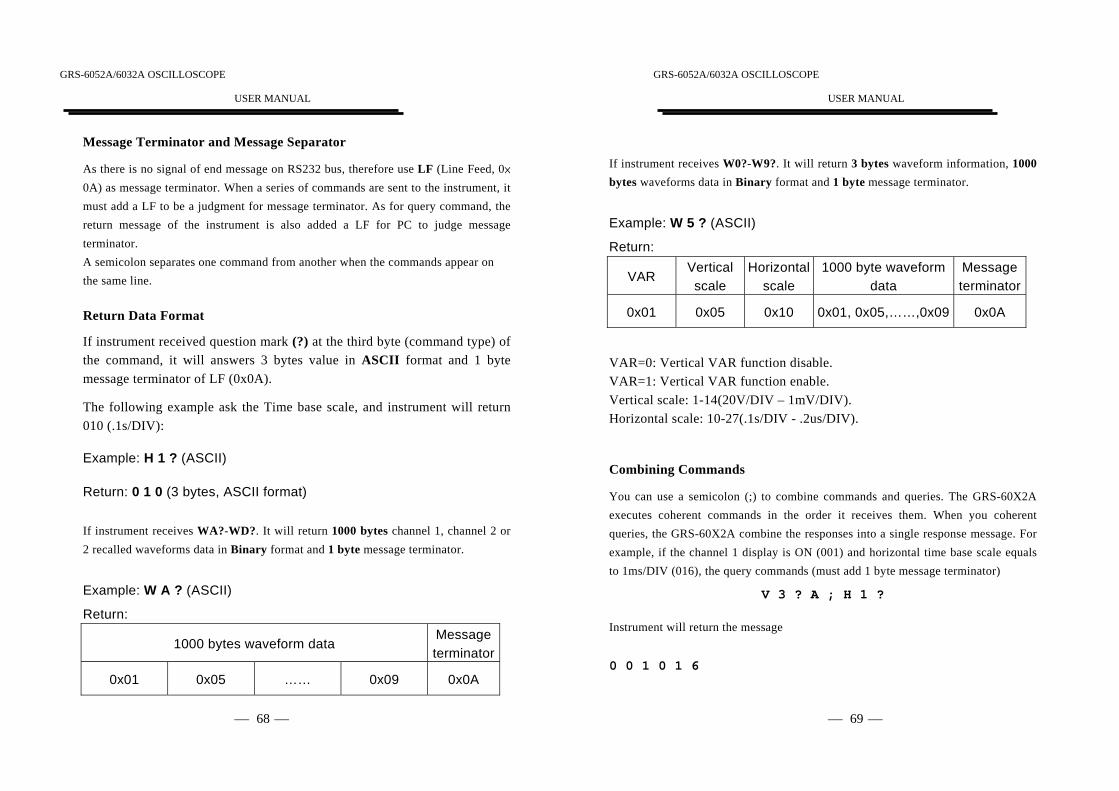
As there is no signal of end message on RS232 bus, therefore use LF (Line Feed, 0×0A) as message terminator. When a series of commands are sent to the instrument, itmust add a LF to be a judgment for message terminator. As for query command, thereturn message of the instrument is also added a LF for PC to judge messageterminator.A semicolon separates one command from another when the commands appear onthe same line.
Return Data Format
If instrument received question mark (?) at the third byte (command type) ofthe command, it will answers 3 bytes value in ASCII format and 1 bytemessage terminator of LF (0x0A).
The following example ask the Time base scale, and instrument will return010 (.1s/DIV):
Example: H 1 ? (ASCII)
Return: 0 1 0 (3 bytes, ASCII format)
If instrument receives WA?-WD?. It will return 1000 bytes channel 1, channel 2 or2 recalled waveforms data in Binary format and 1 byte message terminator.
Example: W A ? (ASCII)
Return:
1000 bytes waveform dataMessageterminator
0x01 0x05 …… 0x09 0x0A
GRS-6052A/6032A OSCILLOSCOPE
USER MANUAL
⎯ ⎯69
If instrument receives W0?-W9?. It will return 3 bytes waveform information, 1000bytes waveforms data in Binary format and 1 byte message terminator.
Example: W 5 ? (ASCII)
Return:
VARVerticalscale
Horizontalscale
1000 byte waveformdata
Messageterminator
0x01 0x05 0x10 0x01, 0x05,……,0x09 0x0A
VAR=0: Vertical VAR function disable.VAR=1: Vertical VAR function enable.Vertical scale: 1-14(20V/DIV – 1mV/DIV).Horizontal scale: 10-27(.1s/DIV - .2us/DIV).
Combining Commands
You can use a semicolon (;) to combine commands and queries. The GRS-60X2Aexecutes coherent commands in the order it receives them. When you coherentqueries, the GRS-60X2A combine the responses into a single response message. Forexample, if the channel 1 display is ON (001) and horizontal time base scale equalsto 1ms/DIV (016), the query commands (must add 1 byte message terminator)
V 3 ? A ; H 1 ?
Instrument will return the message
0 0 1 0 1 6

GRS-6052A/6032A OSCILLOSCOPE
USER MANUAL
⎯ ⎯70
Buffer Size
The command receive buffer of instrument is 128 bytes. The return message bufferof instrument is 1024 bytes.If your combining commands size is larger than 128 bytes, commands will be lost.If you query the waveform data (WA? or WB?), the instrument will return 1000bytes waveform data. Do not use any query commands during the data transmission.
GRS-6052A/6032A OSCILLOSCOPE
USER MANUAL
⎯ ⎯71
Command List
Note: Every command must add 1 byte message terminator of LF (0x0A).
Function Transmission Format
*IDN? *IDN?
*CLR *CLR
*ULK *ULK
*RST *RST
Vertical ScaleV1=<Parameters (3bytes)><Target (1byte)>
V1? <Target (1byte)>
Input CouplingV2=<Parameters (3bytes)><Target (1byte)>
V2? <Target (1byte)>
DisplayV3=<Parameters (3bytes)><Target (1byte)>
V3? <Target (1byte)>
ProbeV4=<Parameters (3bytes)><Target (1byte)>
V4? <Target (1byte)>
V-VARV5=<Parameters (3bytes)><Target (1byte)>
V5? <Target (1byte)>
InvertV6=<Parameters (3bytes)>
V6?
ADDV7=<Parameters (3bytes)>
V7?
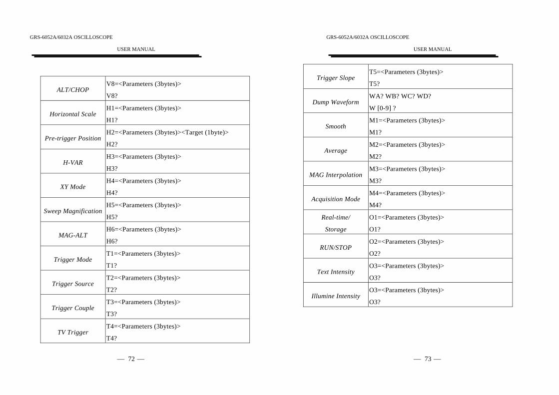
GRS-6052A/6032A OSCILLOSCOPE
USER MANUAL
⎯ ⎯72
ALT/CHOPV8=<Parameters (3bytes)>
V8?
Horizontal ScaleH1=<Parameters (3bytes)>
H1?
Pre-trigger PositionH2=<Parameters (3bytes)><Target (1byte)>
H2?
H-VARH3=<Parameters (3bytes)>
H3?
XY ModeH4=<Parameters (3bytes)>
H4?
Sweep MagnificationH5=<Parameters (3bytes)>
H5?
MAG-ALTH6=<Parameters (3bytes)>
H6?
Trigger ModeT1=<Parameters (3bytes)>
T1?
Trigger SourceT2=<Parameters (3bytes)>
T2?
Trigger CoupleT3=<Parameters (3bytes)>
T3?
TV TriggerT4=<Parameters (3bytes)>
T4?
GRS-6052A/6032A OSCILLOSCOPE
USER MANUAL
⎯ ⎯73
Trigger SlopeT5=<Parameters (3bytes)>
T5?
Dump WaveformWA? WB? WC? WD?
W [0-9] ?
SmoothM1=<Parameters (3bytes)>
M1?
AverageM2=<Parameters (3bytes)>
M2?
MAG InterpolationM3=<Parameters (3bytes)>
M3?
Acquisition ModeM4=<Parameters (3bytes)>
M4?
Real-time/
Storage
O1=<Parameters (3bytes)>
O1?
RUN/STOPO2=<Parameters (3bytes)>
O2?
Text IntensityO3=<Parameters (3bytes)>
O3?
Illumine IntensityO3=<Parameters (3bytes)>
O3?
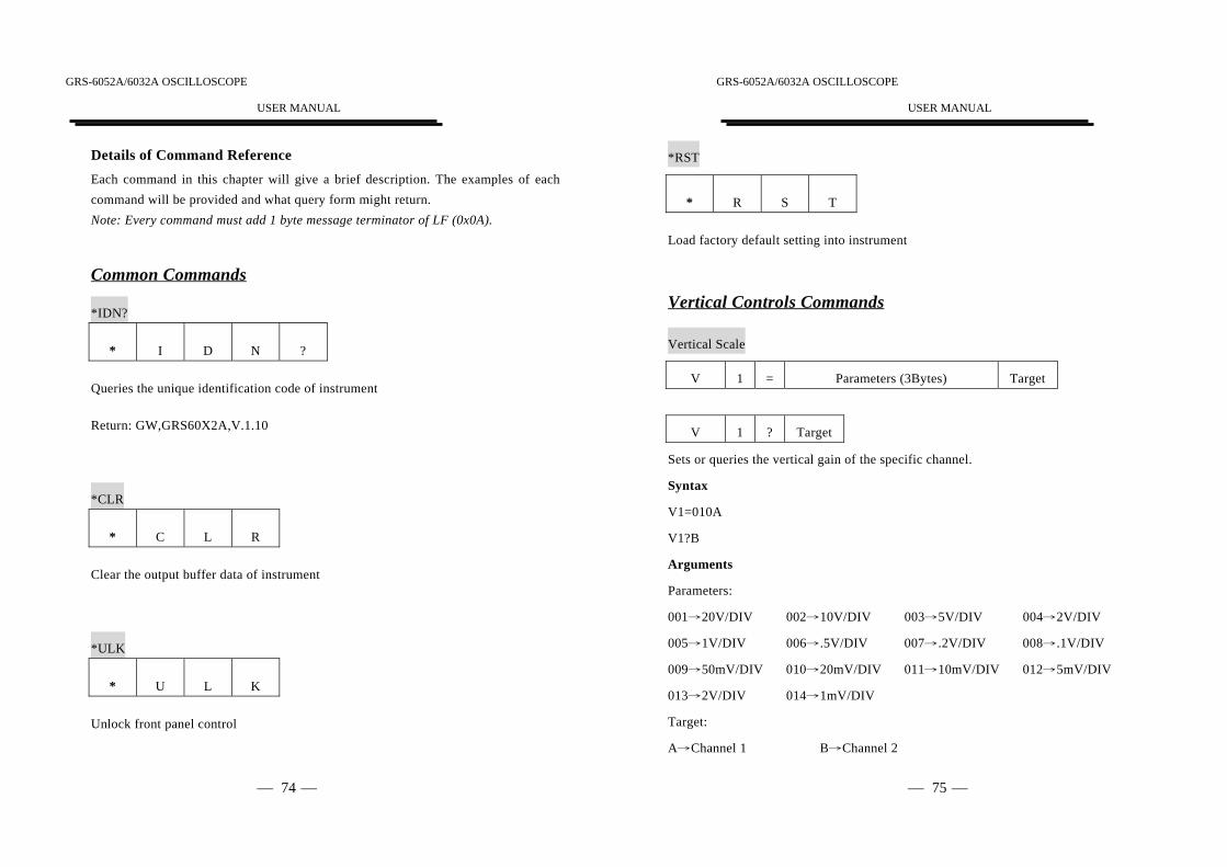
GRS-6052A/6032A OSCILLOSCOPE
USER MANUAL
⎯ ⎯74
Details of Command ReferenceEach command in this chapter will give a brief description. The examples of eachcommand will be provided and what query form might return.Note: Every command must add 1 byte message terminator of LF (0x0A).
Common Commands
*IDN?
* I D N ?
Queries the unique identification code of instrument
Return: GW,GRS60X2A,V.1.10
*CLR
* C L R
Clear the output buffer data of instrument
*ULK
* U L K
Unlock front panel control
GRS-6052A/6032A OSCILLOSCOPE
USER MANUAL
⎯ ⎯75
*RST
* R S T
Load factory default setting into instrument
Vertical Controls Commands
Vertical Scale
V 1 = Parameters (3Bytes) Target
V 1 ? Target
Sets or queries the vertical gain of the specific channel.
Syntax
V1=010A
V1?B
Arguments
Parameters:
001→20V/DIV 002→10V/DIV 003→5V/DIV 004→2V/DIV
005→1V/DIV 006→.5V/DIV 007→.2V/DIV 008→.1V/DIV
009→50mV/DIV 010→20mV/DIV 011→10mV/DIV 012→5mV/DIV
013→2V/DIV 014→1mV/DIV
Target:
A→Channel 1 B→Channel 2

GRS-6052A/6032A OSCILLOSCOPE
USER MANUAL
⎯ ⎯76
Input Coupling
V 2 = Parameters (3Bytes) Target
V 2 ? Target
Sets or queries the input coupling states.
Syntax
V2=001B
V2?A
Arguments
Parameters:
000→Place scope in DC coupling state
001→Place scope in AC coupling state
002→Place scope in grounding state
Target:
A→Channel 1 B→Channel 2
Display
V 3 = Parameters (3Bytes) Target
V 3 ? Target
GRS-6052A/6032A OSCILLOSCOPE
USER MANUAL
⎯ ⎯77
Sets or queries the channel’s display.
Syntax
V3=001A
V3?B
Arguments
Parameters:
000→Disable channel display 001→Enable channel display
Target:
A→Channel 1 B→Channel 2
Probe
V 4 = Parameters (3Bytes) Target
V 4 ? Target
Sets or queries the probe attenuation factor.
Syntax
V4=001B
V4?A
Arguments
Parameters:
000→1X 001→10X

GRS-6052A/6032A OSCILLOSCOPE
USER MANUAL
⎯ ⎯78
Target:
A→Channel 1 B→Channel 2
V-VAR
V 5 = Parameters (3Bytes) Target
V 5 ? Target
Sets or queries the vertical VAR function of the specified channel.
Syntax
V5=071A
V5=?B
Arguments
Parameters:
001 (uncalibrated, Max) to 71 (uncalibrated, Min) →Enable vertical VAR function
and sets VAR value.
000 (calibrated) →Disable vertical VAR function.
Target:
A→Channel 1 B→Channel 2
Invert
V 6 = Parameters (3Bytes)
GRS-6052A/6032A OSCILLOSCOPE
USER MANUAL
⎯ ⎯79
V 6 ?
Sets or queries the invert function.
Syntax
V6=001
V6?
Arguments
Parameters
000→Disable invert function
001→Enable invert function
ADD
V 7 = Parameters (3Bytes)
V 7 ?
Sets or queries the addition function.
Syntax
V7=001
V7?
Arguments
Parameters:
000→Disable the addition function
001→Enable the addition function

GRS-6052A/6032A OSCILLOSCOPE
USER MANUAL
⎯ ⎯80
ALT/CHOP
V 8 = Parameters (3Bytes)
V 8 ?
Sets or queries the ALT/CHOP mode.
Syntax
V8=001
V8?
Arguments
Parameters:
000→ALT mode
001→CHOP mode
Horizontal Controls Commands
Horizontal Scale
H 1 = Parameters (3Bytes)
H 1 ?
Sets or queries the horizontal time base scale.
Syntax
H1=010
GRS-6052A/6032A OSCILLOSCOPE
USER MANUAL
⎯ ⎯81
H1?
Arguments
Parameters:
001→100s/DIV 002→50s/DIV 003→20s/DIV
004→10s/DIV 005→5s/DIV 006→2s/DIV
007→1s/DIV 008→.5s/DIV 009→.2s/DIV
010→.1s/DIV 011→50ms/DIV 012→20ms/DIV
013→10ms/DIV 014→5ms/DIV 015→2ms/DIV
016→1ms/DIV 017→.5ms/DIV 018→.2ms/DIV
019→.1ms/DIV 020→50us/DIV 021→20us/DIV
022→10us/DIV 023→5us/DIV 024→2us/DIV
025→1us/DIV 026→.5us/DIV 027→.2us/DIV
Pre-trigger Position
H 2 = Parameters (3Bytes) Target
H 2 ? Target
Sets or queries the horizontal pre-trigger position.
Syntax
H2=300A
H2=100B
H2?

GRS-6052A/6032A OSCILLOSCOPE
USER MANUAL
⎯ ⎯82
Arguments
Parameters:
If Target=A, Parameter range→0 (0 DIV) to 500 (-10DIV)
If Target=B, Parameter range→0 (0DIV) to 200 (4 DIV)
Target:
A→Pre B→Post
H-VAR
H 3 = Parameters (3Bytes)
H 3 ?
Sets or queries the horizontal VAR function.
Syntax
H3=128
H3?
Arguments
Parameters:
080 (uncalibrated, Max) to 255 (uncalibrated, Min) →Enable horizontal VAR
function and sets VAR value
000 (calibrated) →Disable horizontal VAR function
GRS-6052A/6032A OSCILLOSCOPE
USER MANUAL
⎯ ⎯83
XY Mode
H 4 = Parameters (3Bytes)
H 4 ?
Sets or queries the XY mode
Syntax
H4=001
H4?
Arguments
Parameters:
000→Disable XY mode
001→Enable XY mode
Sweep Magnification
H 5 = Parameters (3Bytes)
H 5 ?
Sets or queries the MAG function.
Syntax
H5=002
H5?

GRS-6052A/6032A OSCILLOSCOPE
USER MANUAL
⎯ ⎯84
Arguments
Parameters:
000→MAG Disable 001→X5
002→X10 003→X20
MAG-ALT
H 6 = Parameters (3Bytes)
H 6 ?
Sets or queries the MAG-ALT mode
Syntax
H6=001
H6?
Arguments
Parameters:
000→Disable MAG-ALT mode
001→Enable MAG-ALT mode
GRS-6052A/6032A OSCILLOSCOPE
USER MANUAL
⎯ ⎯85
Trigger Commands
Trigger Mode
T 1 = Parameters (3Bytes)
T 1 ?
Sets or queries trigger mode
Syntax
T1=001
T1?
Arguments
Parameters:
000→Auto trigger mode 001→Normal trigger mode
002→Single trigger mode
Trigger Source
T 2 = Parameters (3Bytes)
T 2 ?
Sets or queries the trigger source
Syntax
T2=001

GRS-6052A/6032A OSCILLOSCOPE
USER MANUAL
⎯ ⎯86
T2?
Arguments
Parameters:
000→VERT 001→Channel 1
002→Channel 2 003→Line
004→External
Trigger Coupling
T 3 = Parameters (3Bytes)
T 3 ?
Sets or queries the trigger coupling
Syntax
T3=001
T3?
Arguments
Parameters:
000→AC couple 001→High frequency reject
002→Low frequency reject
TV Trigger
T 4 = Parameters (3Bytes)
GRS-6052A/6032A OSCILLOSCOPE
USER MANUAL
⎯ ⎯87
T 4 ?
Sets or queries TV trigger mode
Syntax
T4=001
T4?
Arguments
Parameters:
000→Disable TV trigger.
001→Vertical TV trigger mode 002→Horizontal TV trigger mode
Trigger Slope
T 5 = Parameters (3Bytes)
T 5 ?
Sets or queries trigger slope mode
Syntax
T5=001
T5?
Arguments
Parameters:
000→Negative trigger slope 001→Positive trigger slope

GRS-6052A/6032A OSCILLOSCOPE
USER MANUAL
⎯ ⎯88
Waveform Data Commands
Dump Waveform
W A ?
Dump channel 1 waveform data
W B ?
Dump channel 2 waveform data
W C-D ?
Dump 2 recalled waveform data
W 0-9 ?
Dump REF 0-9 waveform data
Syntax
WA?
W5?
Note: GRS 60x2A can’t return waveform data in real-time mode or in roll
mode( 100s/DIV to .2s/DIV) of storage mode.
GRS-6052A/6032A OSCILLOSCOPE
USER MANUAL
⎯ ⎯89
Menu Commands
Smooth
M 1 = Parameters (3Bytes)
M 1 ?
Sets or queries the waveform smooth function
Syntax
M1=001
M1?
Arguments
Parameters:
000→Disable Smooth function 001→Enable Smooth function
Average
M 2 = Parameters (3Bytes)
M 2 ?
Sets or queries the waveform average function.
Syntax
M2=006
M2?

GRS-6052A/6032A OSCILLOSCOPE
USER MANUAL
⎯ ⎯90
Arguments
Parameters:
000→Disable average function
001→Average number is 2 002→Average number is 4
003→Average number is 8 004→Average number is 16
005→Average number is 32 006→Average number is 64
007→Average number is 128 008→Average number is 256
MAG Interpolation:
M 3 = Parameters (3Bytes)
M 3 ?
Sets or queries the MAG interpolation function
Syntax
M3=001
M3?
Arguments
Parameters:
000→Dot mode 001→Linear mode
Acquisition Mode:
M 4 = Parameters (3Bytes)
M 4 ?
GRS-6052A/6032A OSCILLOSCOPE
USER MANUAL
⎯ ⎯91
Sets or queries the Acquisition Mode
Syntax
M4=001
M4?
Arguments
Parameters:
001→Normal sampling mode 002→Peak detect mode
003→Persistence mode 004→Envelope mode
005→Average mode
Other Commands
Real-Time/Storage mode:
O 1 = Parameters (3Bytes)
O 1 ?
Sets or queries the instrument operation mode.
Syntax
O1=001
O1?

GRS-6052A/6032A OSCILLOSCOPE
USER MANUAL
⎯ ⎯92
Arguments
Parameters:
001→Real-Time mode 000→Storage mode
Run/Stop:
O 2 = Parameters (3Bytes)
O 2 ?
Sets or queries the waveform Run/Stop function
Syntax
O2=001
O2?
Arguments
Parameters:
000→Stop 001→Run
Text intensity
O 3 = Parameters (3Bytes)
O 3 ?
Sets or queries the text intensity
GRS-6052A/6032A OSCILLOSCOPE
USER MANUAL
⎯ ⎯93
Syntax
O3=030
O3?
Arguments
Parameters:
000→Disable text display 001 (Min) to 060 (Max)→Text intensity
Illumine intensity
O 4 = Parameters (3Bytes)
O 4 ?
Sets or queries the illumine intensity
Syntax
O4=125
O4=00?
Arguments
Parameters:
000→Disable illumine display 001 (Min) to 240 (Max)→Illumine intensity
GRS-6052A/6032A OSCILLOSCOPE
USER MANUAL
⎯ ⎯94
6. MAINTENENCEThe instructions below are executed by qualified personnel only. To avoid
electrical shock, do not perform any servicing other than the operating instructionsunless you are qualified to do so.
6-1. Fuse ReplacementIf the fuse blows, the power lamp indicators will not light and the oscilloscopewill not start. The fuse should not normally open unless a problem has
developed in the unit. Try to determine and correct the cause of the blown fuse
and replace only with a fuse of the correct rating and type on the rear panel.
WARNING. For continued fire protection. Replace fuse onlywith 250V fuse of the specified type and rating, and disconnect
power cord before replacing fuse.
6-2. Line Voltage ConversionThe primary winding of the power transformer is tapped to permit operation
from 100, 120, or 230VAC 50/60Hz line voltage. Conversion from one line
voltage to another is done by changing the line voltage selector switch asshown in page 9. The rear panel identifies the line voltage to which the unit
was factory set. To convert to a different line voltage, perform the following
procedure:
(1). Make sure the power cord is unplugged.
(2). Adjust the line voltage selector switch to the desired line voltage position.
(3). A change in line voltage may also require a corresponding change of fusevalue. Install the correct fuse value as listed on rear panel.
GRS-6052A/6032A OSCILLOSCOPE
USER MANUAL
⎯ ⎯95
6-3. CleaningTo clean the oscilloscope, use a soft cloth dampened in a solution of milddetergent and water. Do not spray cleaner directly onto the oscilloscope
because it may leak into the cabinet and cause damage.
Do not use chemicals containing benzine, benzene, toluene, xylene, acetone, orsimilar solvents. Do not use abrasive cleaners on any portion of theoscilloscope.

GRS-6052A/6032A OSCILLOSCOPE
USER MANUAL
⎯ ⎯96
7.Block Diagram
GRS-6052A/6032A OSCILLOSCOPE
USER MANUAL
⎯ ⎯1