gs1 af1, af2 p, af3 p, af4 p - schneider electric · pdf filegs1 af1, af2 p, af3 p, af4 p gs1...
TRANSCRIPT

2
1
3
4
5
6
7
8
9
10
2
1
3
4
5
6
7
8
9
10
24114-EN.indd version: 3.0 2
GS1 APp
GS1 AF1, AF2p, AF3p, AF4p
GS1 AN11
GS1 AN22
GS1 AMp
GS2 AE2p
GS2 AE2p
GS2 AH51pGS2 AH53p GS1 APp
GS2 AH220GS2 AH240
GS1 AF
50…400 A - External operator
2
1
3
4
5
6
7
8
9
10
2
1
3
4
5
6
7
8
9
10
24114-EN.indd version: 3.0 3
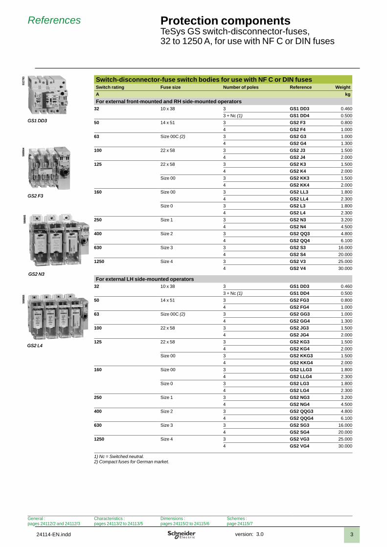
Switch-disconnector-fuse switch bodies for use with NF C or DIN fuses Switch rating Fuse size Number of poles Reference WeightA kgFor external front-mounted and RH side-mounted operators
32 10 x 38 3 GS1 DD3 0.4603 + Nc (1) GS1 DD4 0.500
50 14 x 51 3 GS2 F3 0.8004 GS2 F4 1.000
63 Size 00C (2) 3 GS2 G3 1.0004 GS2 G4 1.300
100 22 x 58 3 GS2 J3 1.5004 GS2 J4 2.000
125 22 x 58 3 GS2 K3 1.5004 GS2 K4 2.000
Size 00 3 GS2 KK3 1.5004 GS2 KK4 2.000
160 Size 00 3 GS2 LL3 1.8004 GS2 LL4 2.300
Size 0 3 GS2 L3 1.8004 GS2 L4 2.300
250 Size 1 3 GS2 N3 3.2004 GS2 N4 4.500
400 Size 2 3 GS2 QQ3 4.8004 GS2 QQ4 6.100
630 Size 3 3 GS2 S3 16.0004 GS2 S4 20.000
1250 Size 4 3 GS2 V3 25.0004 GS2 V4 30.000
For external LH side-mounted operators32 10 x 38 3 GS1 DD3 0.460
3 + Nc (1) GS1 DD4 0.50050 14 x 51 3 GS2 FG3 0.800
4 GS2 FG4 1.00063 Size 00C (2) 3 GS2 GG3 1.000
4 GS2 GG4 1.300100 22 x 58 3 GS2 JG3 1.500
4 GS2 JG4 2.000125 22 x 58 3 GS2 KG3 1.500
4 GS2 KG4 2.000Size 00 3 GS2 KKG3 1.500
4 GS2 KKG4 2.000160 Size 00 3 GS2 LLG3 1.800
4 GS2 LLG4 2.300Size 0 3 GS2 LG3 1.800
4 GS2 LG4 2.300250 Size 1 3 GS2 NG3 3.200
4 GS2 NG4 4.500400 Size 2 3 GS2 QQG3 4.800
4 GS2 QQG4 6.100630 Size 3 3 GS2 SG3 16.000
4 GS2 SG4 20.0001250 Size 4 3 GS2 VG3 25.000
4 GS2 VG4 30.000
1) Nc = Switched neutral.2) Compact fuses for German market.
GS1 DD3
5327
83
GS1 DD3
5327
83
GS2 F3
5686
64
GS2 F3
5686
64
GS2 N3
5686
65
GS2 N3
5686
65
GS2 L4
5686
66
GS2 L4
5686
66
General :pages 24112/2 and 24112/3
Characteristics :pages 24113/2 to 24113/5
Dimensions :pages 24115/2 to 24115/6
Schemes :page 24115/7
References Protection componentsTeSys GS switch-disconnector-fuses, 32 to 1250 A, for use with NF C or DIN fuses

2
1
3
4
5
6
7
8
9
10
2
1
3
4
5
6
7
8
9
10
24114-EN.indd version: 3.0 4
GS1 AF1, AF2p, AF3p, AF4p
GS1 AF
GS1 AM1
GS1 AM2
GS1 APp
GS1 AN11
GS1 AN22
GS1 AH01GS1 AH02
GS1 APp
50…400 A - Direct operator
2
1
3
4
5
6
7
8
9
10
2
1
3
4
5
6
7
8
9
10
24114-EN.indd version: 3.0 5
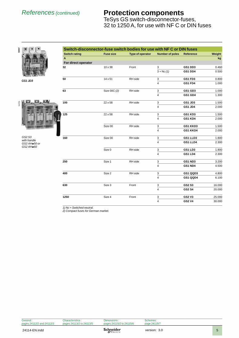
Switch-disconnector-fuse switch bodies for use with NF C or DIN fuses Switch rating Fuse size Type of operator Number of poles Reference WeightA kgFor direct operator
32 10 x 38 Front 3 GS1 DD3 0.4603 + Nc (1) GS1 DD4 0.500
50 14 x 51 RH side 3 GS1 FD3 0.8004 GS1 FD4 1.000
63 Size 00C (2) RH side 3 GS1 GD3 1.0004 GS1 GD4 1.300
100 22 x 58 RH side 3 GS1 JD3 1.5004 GS1 JD4 2.000
125 22 x 58 RH side 3 GS1 KD3 1.5004 GS1 KD4 2.000
Size 00 RH side 3 GS1 KKD3 1.5004 GS1 KKD4 2.000
160 Size 00 RH side 3 GS1 LLD3 1.8004 GS1 LLD4 2.300
Size 0 RH side 3 GS1 LD3 1.8004 GS1 LD4 2.300
250 Size 1 RH side 3 GS1 ND3 3.2004 GS1 ND4 4.500
400 Size 2 RH side 3 GS1 QQD3 4.8004 GS1 QQD4 6.100
630 Size 3 Front 3 GS2 S3 16.0004 GS2 S4 20.000
1250 Size 4 Front 3 GS2 V3 25.0004 GS2 V4 30.000
1) Nc = Switched neutral.2) Compact fuses for German market.
GS1 JD3
5686
67
GS1 JD3
5686
67
References (continued) Protection componentsTeSys GS switch-disconnector-fuses, 32 to 1250 A, for use with NF C or DIN fuses
General :pages 24112/2 and 24112/3
Characteristics :pages 24113/2 to 24113/5
Dimensions :pages 24115/2 to 24115/6
Schemes :page 24115/7
GS2 S3with handleGS2 AHp50 orGS2 AHp60
5107
61

2
1
3
4
5
6
7
8
9
10
2
1
3
4
5
6
7
8
9
10
24114-EN.indd version: 3.0 6
GS2 AE8p
GS2 AH51p
GS1 AH103
GS1 AMp
GS1 AMp11 GS2 AE8p
GS1 AD10
GS2 AH220
32 A - Direct or external operator

2
1
3
4
5
6
7
8
9
10
2
1
3
4
5
6
7
8
9
10
24114-EN.indd version: 3.0 7
Switch-disconnector-fuse switch bodies for use with BS fuses Switch rating Fuse size Number of poles Reference WeightA kgFor external front-mounted and RH or LH side-mounted operatorFor direct front-mounted operator
32 A1 3 GS1 DDB3 0.5003 + Nc (1) GS1 DDB4 0.540
For external front-mounted and RH side-mounted operators (2)32 A1 3 GS2 DB3 0.800
4 GS2 DB4 1.000
63 A2-A3 3 GS2 GB3 1.0004 GS2 GB4 1.300
100 A4 Ø y 31 mm 3 GS2 JB3 1.5004 GS2 JB4 2.000
160 A4 3 GS2 LLB3 1.8004 GS2 LLB4 2.300
B1-B2 3 GS2 LB3 1.8004 GS2 LB4 2.300
200 B1-B2 3 GS2 MMB3 3.2004 GS2 MMB4 4.500
250 B1…B3 3 GS2 NB3 3.2004 GS2 NB4 4.500
315 B1…B3 3 GS2 PPB3 4.8004 GS2 PPB4 6.100
400 B1…B4 3 GS2 QQB3 4.8004 GS2 QQB4 6.100
630 C 1-C2 3 GS2 SB3 (2) 16.0004 GS2 SB4 (2) 20.000
800 C 1…C3 3 GS2 TB3 (2) 17.0004 GS2 TB4 (2) 21.500
1250 D1 3 GS2 VB3 (2) 25.0004 GS2 VB4 (2) 30.000
(1) Nc: switched neutral.(2) 630, 800 and 1250 A switch-disconnector-fuses can also be fi tted with a direct front-mounted operator.
General :pages 24112/2 and 24112/3
Characteristics :pages 24113/2 to 24113/5
Dimensions :pages 24115/2 to 24115/6
Schemes :page 24115/7
References (continued) Protection componentsTeSys GS switch-disconnector-fuses, 32 to 1250 A, for use with BS fuses
GS1 DDB3
5109
61
GS2 GB3
5109
67
2
1
3
4
5
6
7
8
9
10
2
1
3
4
5
6
7
8
9
10
24114-EN.indd version: 3.0 8
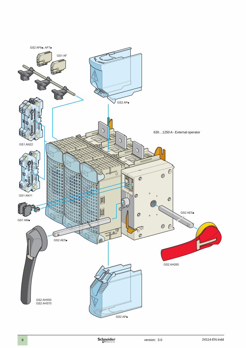
GS2 APp
GS2 APp
GS2 AH260
GS2 AF6p, AF7p
GS1 AF
GS1 AMp
GS2 AE5p
GS2 AE5p
GS1 AN11
GS2 AH550GS2 AH570
GS1 AN22
630…1250 A - External operator
2
1
3
4
5
6
7
8
9
10
2
1
3
4
5
6
7
8
9
10
24114-EN.indd version: 3.0 9
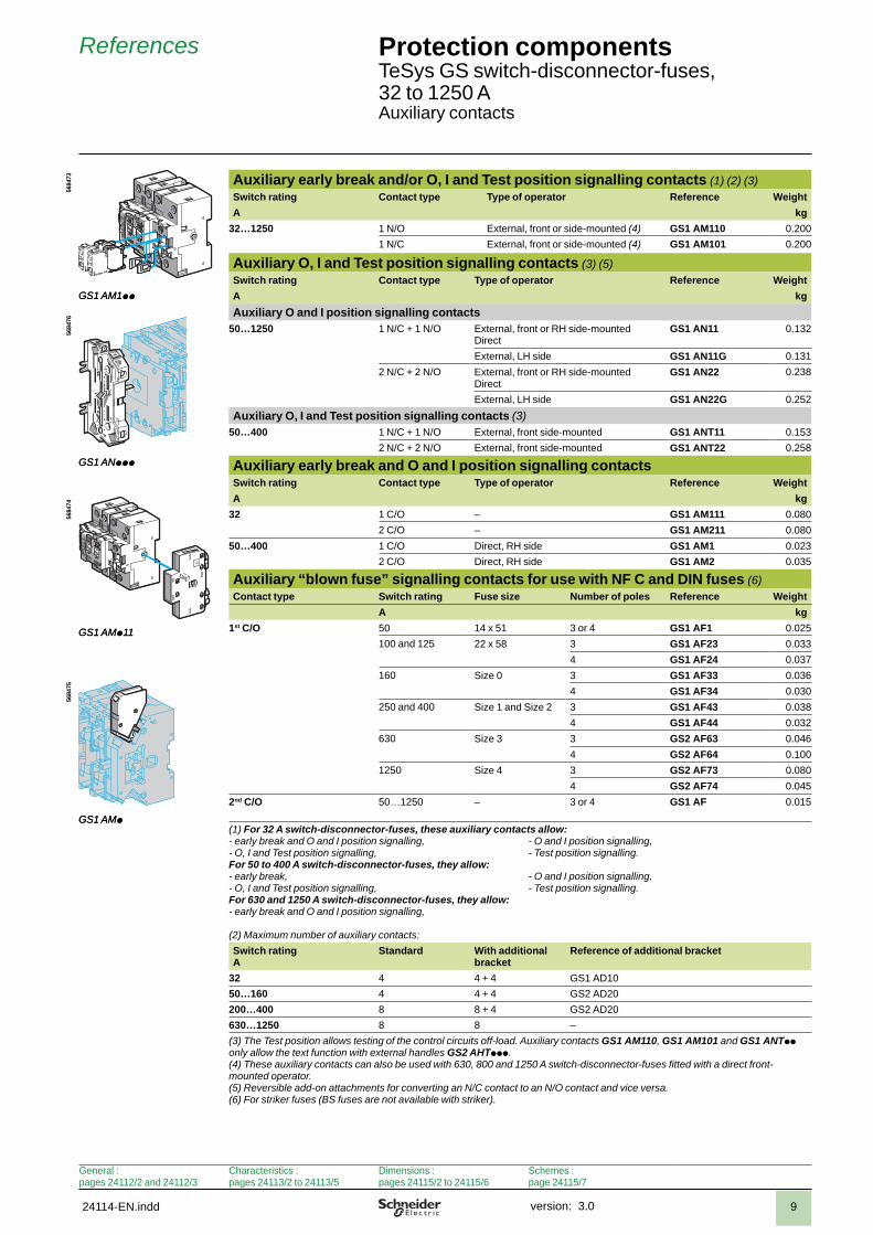
Auxiliary early break and/or O, I and Test position signalling contacts (1) (2) (3) Switch rating Contact type Type of operator Reference WeightA kg
32…1250 1 N/O External, front or side-mounted (4) GS1 AM110 0.2001 N/C External, front or side-mounted (4) GS1 AM101 0.200
Auxiliary O, I and Test position signalling contacts (3) (5) Switch rating Contact type Type of operator Reference WeightA kgAuxiliary O and I position signalling contacts
50…1250 1 N/C + 1 N/O External, front or RH side-mountedDirect
GS1 AN11 0.132
External, LH side GS1 AN11G 0.1312 N/C + 2 N/O External, front or RH side-mounted
DirectGS1 AN22 0.238
External, LH side GS1 AN22G 0.252Auxiliary O, I and Test position signalling contacts (3)
50…400 1 N/C + 1 N/O External, front side-mounted GS1 ANT11 0.1532 N/C + 2 N/O External, front side-mounted GS1 ANT22 0.258
Auxiliary early break and O and I position signalling contacts Switch rating Contact type Type of operator Reference WeightA kg
32 1 C/O – GS1 AM111 0.0802 C/O – GS1 AM211 0.080
50…400 1 C/O Direct, RH side GS1 AM1 0.0232 C/O Direct, RH side GS1 AM2 0.035
Auxiliary “blown fuse” signalling contacts for use with NF C and DIN fuses (6) Contact type Switch rating Fuse size Number of poles Reference Weight
A kg1st C/O 50 14 x 51 3 or 4 GS1 AF1 0.025
100 and 125 22 x 58 3 GS1 AF23 0.0334 GS1 AF24 0.037
160 Size 0 3 GS1 AF33 0.0364 GS1 AF34 0.030
250 and 400 Size 1 and Size 2 3 GS1 AF43 0.0384 GS1 AF44 0.032
630 Size 3 3 GS2 AF63 0.0464 GS2 AF64 0.100
1250 Size 4 3 GS2 AF73 0.0804 GS2 AF74 0.045
2nd C/O 50…1250 – 3 or 4 GS1 AF 0.015
(1) For 32 A switch-disconnector-fuses, these auxiliary contacts allow:- early break and O and I position signalling, - O and I position signalling,- O, I and Test position signalling, - Test position signalling.For 50 to 400 A switch-disconnector-fuses, they allow:- early break, - O and I position signalling,- O, I and Test position signalling, - Test position signalling.For 630 and 1250 A switch-disconnector-fuses, they allow:- early break and O and I position signalling,
(2) Maximum number of auxiliary contacts:Switch rating A
Standard With additional bracket
Reference of additional bracket
32 4 4 + 4 GS1 AD1050…160 4 4 + 4 GS2 AD20200…400 8 8 + 4 GS2 AD20630…1250 8 8 –(3) The Test position allows testing of the control circuits off-load. Auxiliary contacts GS1 AM110, GS1 AM101 and GS1 ANTpp only allow the text function with external handles GS2 AHTppp.(4) These auxiliary contacts can also be used with 630, 800 and 1250 A switch-disconnector-fuses fi tted with a direct front-mounted operator.(5) Reversible add-on attachments for converting an N/C contact to an N/O contact and vice versa.(6) For striker fuses (BS fuses are not available with striker).
GS1 AM1pp
5684
73
GS1 AM1pp
5684
73
GS1 AMp11
5684
74
GS1 AMp11
5684
74
GS1 ANppp
5684
76
GS1 ANppp
5684
76
GS1 AMp
5684
75
GS1 AMp
5684
75
General :pages 24112/2 and 24112/3
Characteristics :pages 24113/2 to 24113/5
Dimensions :pages 24115/2 to 24115/6
Schemes :page 24115/7
References Protection componentsTeSys GS switch-disconnector-fuses, 32 to 1250 A Auxiliary contacts

2
1
3
4
5
6
7
8
9
10
2
1
3
4
5
6
7
8
9
10
24114-EN.indd version: 3.0 10
Handles for external operator Switch rating Handle colour Degree of protection Reference WeightA kgHandles for front-mounted external operators, padlockable and lockable in position O (1)
Door interlock in I position (2)32…63 Black/Grey IP 65 GS2 AH510 0.200
IP 55 GS2 AH515 0.200Red/Yellow IP 65 GS2 AH520 0.200
100…400 Black/Grey IP 65 GS2 AH530 0.240IP 55 GS2 AH535 0.240
Red/Yellow IP 65 GS2 AH540 0.240630 and 800 Black/Grey IP 65 GS2 AH550 0.280
Red/Yellow IP 65 GS2 AH560 0.2801250 Black/Grey IP 65 GS2 AH570 0.390
Red/Yellow IP 65 GS2 AH580 0.390
Handles for front-mounted external operators with test facility (3), padlockable and lockable in "O" position (1). Door interlock in “I” position (2)
32…63 Black/Grey IP 65 GS2 AHT510 0.200Red/Yellow IP 65 GS2 AHT520 0.200
100…400 Black/Grey IP 65 GS2 AHT530 0.240Red/Yellow IP 65 GS2 AHT540 0.240
Handles for external RH side-mounted operators, padockable and lockable in "O" position (1)32…63 Black/Grey IP 65 GS2 AH210 0.200
IP 55 GS2 AH215 0.200Red/Yellow IP 65 GS2 AH220 0.200
100…400 Black/Grey IP 65 GS2 AH230 0.240IP 55 GS2 AH235 0.240
Red/Yellow IP 65 GS2 AH240 0.240630…1250 Black/Grey IP 65 GS2 AH250 0.280
Red/Yellow IP 65 GS2 AH260 0.280
Handles for external LH side-mounted operators, padockable and lockable in "O" position (1)32…63 Black/Grey IP 65 GS2 AH310 0.200
Red/Yellow IP 65 GS2 AH320 0.200100…400 Black/Grey IP 65 GS2 AH330 0.240
Red/Yellow IP 65 GS2 AH340 0.240630…1250 Black/Grey IP 65 GS2 AH350 0.280
Red/Yellow IP 65 GS2 AH360 0.280
Shafts for external operatorsSwitch rating Shaft length Shaft cross section Reference WeightA mm mm kg
32 200 5 x 5 GS2 AE82 0.100320 5 x 5 GS2 AE8 0.125400 5 x 5 GS2 AE81 0.150
50…400 200 10 x 10 GS2 AE22 0.160320 10 x 10 GS2 AE2 0.280400 10 x 10 GS2 AE21 0.320
630…1250 200 12 x 12 GS2 AE52 0.240320 12 x 12 GS2 AE5 0.380400 12 x 12 GS2 AE51 0.420
(1) Lockable with device GS2 AX1, to be ordered separately.(2) Door interlock override by means of a tool.(3) The Test facility allows testing of the control circuits off-load, by using auxiliary contacts GS1 AM110, GS1 AM101 or GS1 ANTpp. In the “Test” position, the enclosure door can be opened.
References Protection componentsTeSys GS switch-disconnector-fuses, 32 to 1250 A Handles for external operators
5386
53
GS2 AHp70GS2 AHp80
5386
54
GS2 AHp50GS2 AHp60
5386
55
GS2 AHp30GS2 AHp40
5386
56
GS2 AHp10GS2 AHp20
2
1
3
4
5
6
7
8
9
10
2
1
3
4
5
6
7
8
9
10
24114-EN.indd version: 3.0 11
Handles for external operators Switch rating Type of operator Handle colour Reference WeightA kgHandles for direct operators, padlockable
32 Front Black GS1 AH103 0.06050 and 63 RH side Black GS1 AH01 0.060100…400 RH side Black GS1 AH02 0.100630 and 800 Front Black GS2 AH104 0.4801250 Front Black GS2 AH105 0.600
Terminal protection shrouds for upstream or downstream connector platesSwitch rating Number of poles Reference WeightA kg
50 and 63 3 or 4 (1) –100…160 3 GS1 AP33 0.073
4 GS1 AP34 0.180200…400 3 GS1 AP43 0.240
4 GS1 AP44 0.280630…800 3 GS2 AP63 0.520
4 GS2 AP64 0.7801250 3 GS2 AP83 0.680
4 GS2 AP84 0.840
Devices for locking fuse covers in "I" position (2)Switch rating Fuse size Number of poles Reference WeightA kg
50 14 x 51 3 or 4 (3) –63 Size 00C 3 or 4 GS1 AV1 0.012100…160 22 x 58, Size 00 3 or 4 GS1 AV2 0.040160 Size 0 3 GS1 AV33 0.026
4 GS1 AV34 0.010250 Size 1 3 GS1 AV53 0.026
4 GS1 AV54 0.010400 Size 2 3 GS1 AV73 0.027
4 GS1 AV74 0.033
Cage terminals for connection of bare cables (without lug)Switch rating Number of poles Reference WeightA kg
50 and 63 3 or 4 (4) –100…160 3 GS1 AW33 0.179
4 GS1 AW34 0.357200…250 3 GS1 AW43 0.236
4 GS1 AW44 0.480
External handle locking deviceSwitch rating Description Reference WeightA kg
32…1250 Device for RONIS EL11AP key lock (lock to be ordered separately).
GS2 AX1 0.200
Height compensation plate for external handlesSwitch ratingA
Description Degree of protection Reference Weightkg
32…1250 Allows a new GS2pp handle to be fi tted on existing cut-outs
IP 65 GS2 AH001 0.020
Flat mounting kitSwitch rating Description Reference WeightA kg
50…400 The kit, for use with a front-mounted external handle,includes:
a 200 mm shaft, cross section 10 x 10 mm,an adapter plate
bb
GS2 ADL2 0.300
(1) For these ratings, the switch-disconnector-fuses are fi tted with terminal covers as standard.(2) For NF C and DIN switch-disconnector-fuses fi tted with right-hand mounted direct operator.(3) For this rating, switch-disconnector-fuses are fi tted with a cover locking device as standard.(4) For these ratings, switch-disconnector-fuses are fi tted with cage terminals as standard.
GS1 AH01
5686
68
GS1 AH01
5686
68
GS1 AH02
5686
69
GS1 AH02
5686
69
References Protection componentsTeSys GS switch-disconnector-fuses, 32 to 1250 AHandles for external operators Accessories