gsm/gprs shield manual
TRANSCRIPT
GSM/GPRS SHIELD MANUAL
Overview
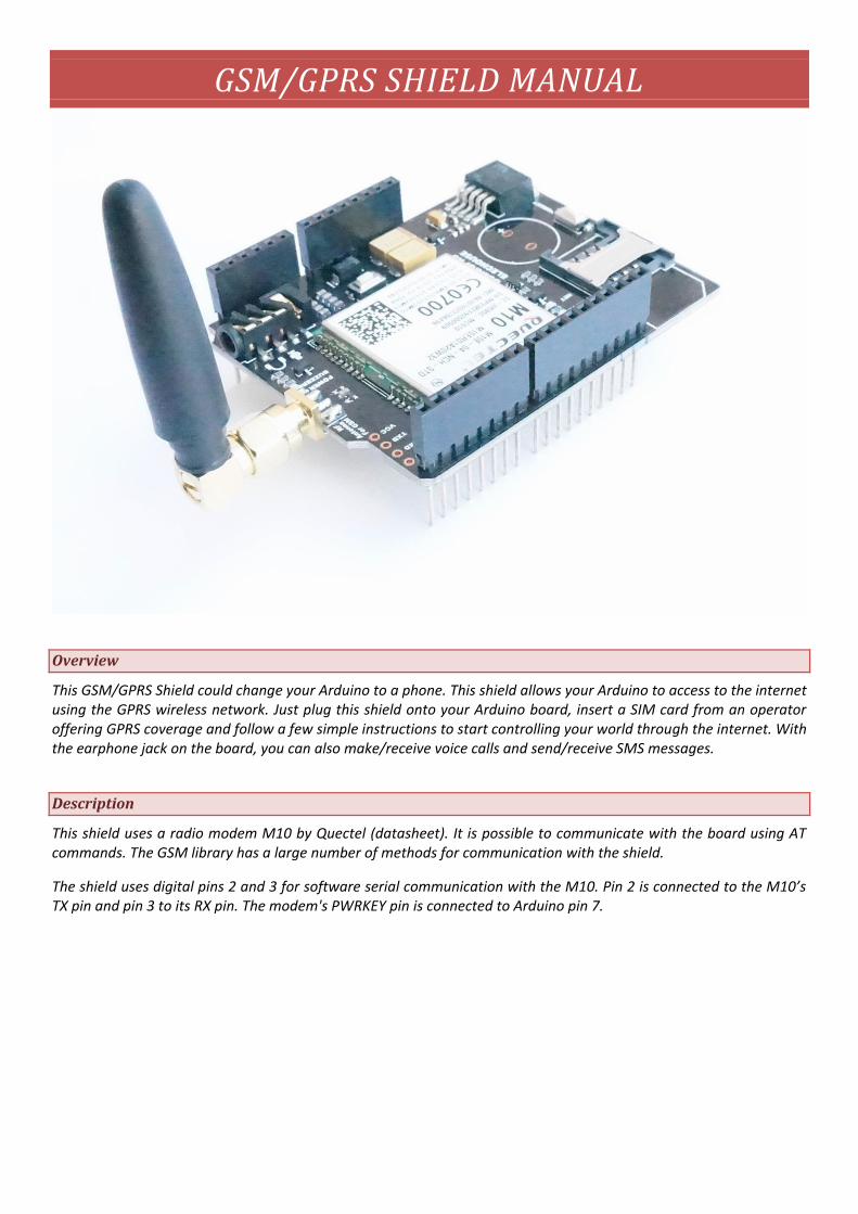
This GSM/GPRS Shield could change your Arduino to a phone. This shield allows your Arduino to access to the internet using the GPRS wireless network. Just plug this shield onto your Arduino board, insert a SIM card from an operator offering GPRS coverage and follow a few simple instructions to start controlling your world through the internet. With the earphone jack on the board, you can also make/receive voice calls and send/receive SMS messages.
Description
This shield uses a radio modem M10 by Quectel (datasheet). It is possible to communicate with the board using AT commands. The GSM library has a large number of methods for communication with the shield.
The shield uses digital pins 2 and 3 for software serial communication with the M10. Pin 2 is connected to the M10’s TX pin and pin 3 to its RX pin. The modem's PWRKEY pin is connected to Arduino pin 7.

The M10 is a Quad-band GSM/GPRS modem that works at frequencies GSM850MHz, GSM900MHz, DCS1800MHz
and PCS1900MHz. It supports TCP/UDP and HTTP protocols through a GPRS connection. GPRS data downlink and
uplink transfer speed maximum is 85.6 kbps.
To interface with the cellular network, the board requires a SIM card provided by a network operator.
Power requirements
It is recommended that the board be powered with an external power supply that can provide between 700mA and 1000mA. Powering an Arduino and the GSM shield from a USB connection could not work, as most PC USB port could not supply enough current.
LED indicators
POWER: shows the Shield gets power.
STATUS: turns on to when the modem is powered and data is being transferred to/from the GSM/GPRS network.
NET: blinks when the modem is communicating with the radio network.
Buzzer: blinks for incoming call
On board interfaces
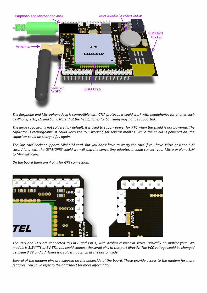
The Earphone and Microphone Jack is compatible with CTIA protocol. It could work with headphones for phones such as iPhone, HTC, LG and Sony. Note that the headphones for Samsung may not be supported.
The large capacitor is not soldered by default. It is used to supply power for RTC when the shield is not powered. The capacitor is rechargeable. It could keep the RTC working for several months. While the shield is powered on, the capacitor could be charged full again.
The SIM card Socket supports Mini SIM card. But you don’t have to worry the card if you have Micro or Nano SIM card. Along with the GSM/GPRS shield we will ship the converting adaptor. It could convert your Micro or Nano SIM to Mini SIM card.
On the board there are 4 pins for GPS connection.
The RXD and TXD are connected to Pin 0 and Pin 1, with 47ohm resistor in series. Basically no matter your GPS module is 3.3V TTL or 5V TTL, you could connect the serial pins to this port directly. The VCC voltage could be changed between 3.3V and 5V. There is a soldering switch at the bottom side.
Several of the modem pins are exposed on the underside of the board. These provide access to the modem for more features. You could refer to the datasheet for more information.

There are two small buttons on the shield. The button labeled "RESET" is tied to the Arduino reset pin. When pressed, it will restart the sketch. The button labeled "PWRKEY" is connected to the modem and will power the modem on and off. Note that while you power on Arduino, the shield will turn the modem on automatically.
Examples
Here we show several examples for Arduino.
Soldering the capacitor
This step is optional. If you need the RTC working while powered off, you may need to solder this capacitor on.

The long pin of the capacitor is marked with “0000” aside and it is the negative pin.
Insert SIM cards

In addition to the GSM/GPRS shield and an Arduino, you need a SIM card.
It's common for SIM cards to have a four-digit PIN number associated with them for security purposes. Keep note of
this number, as it's necessary for connecting to a network. If you lose the PIN associated with your SIM card, you may
need to contact your network operator to retrieve it. Some SIM cards become locked if an incorrect PIN is entered too
many times. If you're unsure of what the PIN is, look at the documentation that came with your SIM.
Using a PUK (PIN Unlock Code), it is possible to reset a lost PIN with the GSM shield and an Arduino. The PUK number
will come with your SIM card documentation.
Look at the PIN Management example in the "tools" folder, bundled with the GSM library for an example of how to
manage your PIN number with the PUK.
There are a few different sizes of SIM cards; the GSM shield accepts cards in the mini-SIM format (25mm long and
15mm wide). If your SIM card is Micro-SIM (typically for iPhone 4) or Nano-SIM (typically for iPhone 5), you could use the
adaptors.
Connecting the Shield

Note: this GSM/GPRS shield is not currently supported on Arduino Due.
Arduino Uno
If you are using an Arduino Uno, just insert the shield onto Arduino Uno.
Arduino Leonardo
The GSM library uses digital pin 8 to communicate with the Leonardo. On the GSM shield, connect a jumper wire
between digital pins 2 and 8.
Bend the male header attached to pin 2 on the GSM shield to the side so it does not connect with the Leonardo.
Arduino Mega

The GSM library uses digital pin 10 to communicate with the Mega. On the GSM shield, connect a jumper wire
between digital pins 2 and 10.
Bend the male header attached to pin 2 on the GSM shield to the side so it does not connect with the Mega.
To upload sketches to the board, connect it to your computer with a USB cable and meanwhile power Arduino with
an external power supply. When the POWER LED turns on, it means the modem is powered, and you can try
connecting to the network.
Software
You need to download Arduino IDE 1.0.4 or later.
Digital pins 2, 3 and 7 on Arduino Uno (or pins 8, 3 and 7 on Arduino Leonardo, or pins 10, 3 and 7 on Arduino Mega)
are reserved for communication between the Arduino and modem and cannot be used by your sketches.
Communication between the modem and Arduino is handled by the Software Serial library on pins 2 and 3 on Arduino
Uno (pins 8 and 3 on Arduino Leonardo, or pins 10 and 3 on Arduino Mega). Pin 7 is used for the modem reset.
The GSM library handles communication between Arduino and the GSM shield. The majority of functions are for
managing data, voice, and SMS communication. There are also a number of utilities for managing information about
the modem and the SIM card's PIN. See the library reference pages for more information and a complete set of
examples.
Testing the modem and network connection
This sketch will check the modem's IMEI number. This number is unique to each modem, and is used to identify valid
devices that can connect to a GSM network. Once the number has been read from the modem, the Arduino will print
out the network carrier it is connected to, and the signal strength of the network over the serial port.
Open the code through the following path:

Upload the sketch to Arduino.
Open Serial Monitor, make sure the baud rate is 9600. You will get the following result:
Wait for some time:

Sending a SMS message
Once you have connected to your network with the sketch above, you can test some of the other functionality of the
board. This sketch will connect to a GSM network and send a SMS message to a phone number of your choosing.
Open the code through the following path:
Upload the sketch to Arduino.
Open Serial Monitor, choose Newline and 9600 baud rate:

Note that you need to wait for some time to get the result above.
Enter the receiver’s phone number, and click “Send” on Serial Monitor or press “Return” on key board.
Now enter the message and click “Send”
Message is sent and it comes back to the option to send another message.
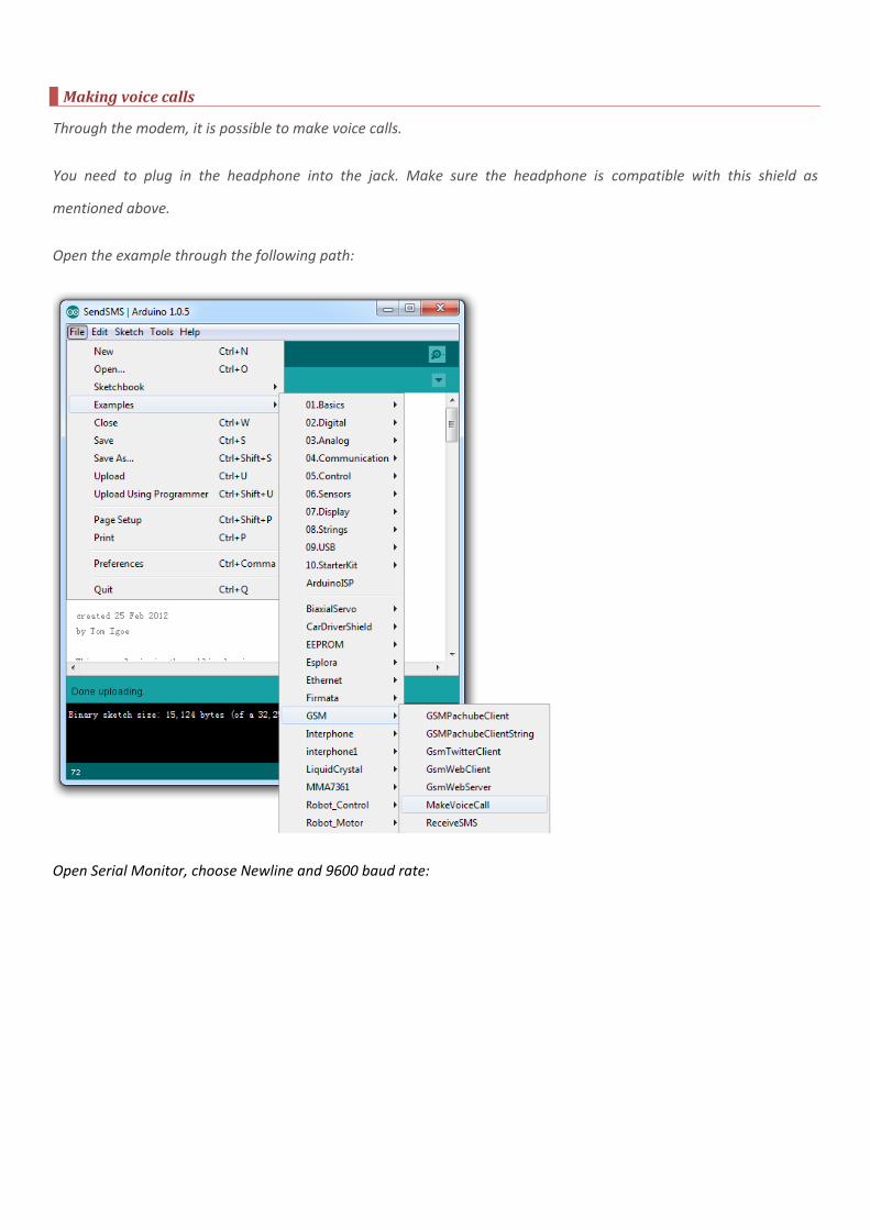
Making voice calls
Through the modem, it is possible to make voice calls.
You need to plug in the headphone into the jack. Make sure the headphone is compatible with this shield as
mentioned above.
Open the example through the following path:
Open Serial Monitor, choose Newline and 9600 baud rate:

Note that you need to wait for some time to get the result above.
Enter a phone number and click “Send”. Then it is calling the number:
Connecting to the internet
The example below will connect to arduino.cc/latest.txt and print out its contents.
NB: Some network operators block incoming IP traffic. You should be able to run client functions, such as the sketch
below, with no issues.
Open the example code through the following path:

In addition to the SIM card and a data plan, you will need some additional information from your cellular provider to
connect to the internet. Every cellular provider has an Access Point Name (APN) that serves as a bridge between the
cellular network and the internet. Sometimes, there is a username and password associated with the connection
point. For example, the Bluevia APN is bluevia.movistar.es, but it has no password or login name.
This page lists a number of carrier's information, but it may not be up to date. You may need to get this information
from your service provider.
To make the code work, you need to modify it:
// APN data
#define GPRS_APN "GPRS_APN" // replace your GPRS APN
#define GPRS_LOGIN "login" // replace with your GPRS login
#define GPRS_PASSWORD "password" // replace with your GPRS password
Upload the sketch to Arduino.
Open Serial Monitor, choose 9600 baud rate:
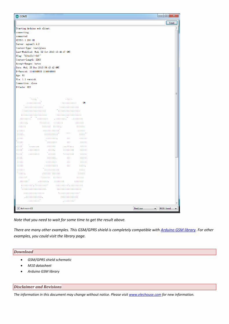
Note that you need to wait for some time to get the result above.
There are many other examples. This GSM/GPRS shield is completely compatible with Arduino GSM library. For other
examples, you could visit the library page.
Download
GSM/GPRS shield schematic
M10 datasheet
Arduino GSM library
Disclaimer and Revisions
The information in this document may change without notice. Please visit www.elechouse.com for new information.

Rev. Date Author Description 1.0 2013-12-26 Wilson Initial Version