gsr amp owner's guide - go-gddq.com · gsr amp owner’s guide 6 safety symbols ... using the...
TRANSCRIPT

GSR Amp
Owner’s Guide

GSR Amp
Owner’s Guide
ii
This document was, as far as possible, accurate at the time of release. However, changes may have been made to the software and hardware it describes since then. ADInstruments Pty Ltd reserves the right to alter specifications as required. Late-breaking information may be supplied separately.
Trademarks of ADInstruments
PowerLab
®
, LabTutor
®
and MacLab
®
are registered trademarks of ADInstruments Pty Ltd. The names of specific recording units, such as PowerLab 8/30, are trademarks of ADInstruments Pty Ltd. LabChart, Chart and Scope (application programs) are trademarks of ADInstruments Pty Ltd.
Other Trademarks
Apple, Mac and Macintosh are registered trademarks of Apple Computer, Inc.
Windows, Windows XP and Windows Vista are either registered trademarks or trademarks of Microsoft Corporation.
All other trademarks are the property of their respective owners.
Product: ML116 GSR Amp
Document Number: U-ML116-OG-002BPart Number: 4615
Copyright © February 2008 ADInstruments Pty Ltd.Unit 13, 22 Lexington Drive, Bella Vista, NSW 2153, Australia
All rights reserved. No part of this document may be reproduced by any means without the prior written permission of ADInstruments Pty Ltd.
Web: www.adinstruments.comTechnical Support: [email protected]: [email protected]
ADInstruments Pty Ltd. ISO 9001:2000 Certified Quality Management System
Reg. No. 1053

Contents
iii
Contents
Safety Notes 5
1 Overview 13
How to Use This Guide. . . . . . . . . . . . . . . . . . . . . . . . . . . . . . . . 14Checking the Front-end. . . . . . . . . . . . . . . . . . . . . . . . . . . . . . 14Front-end Fundamentals . . . . . . . . . . . . . . . . . . . . . . . . . . . . . 14
The Front-end . . . . . . . . . . . . . . . . . . . . . . . . . . . . . . . . . . . . . 15The Front Panel . . . . . . . . . . . . . . . . . . . . . . . . . . . . . . . . . . 15
The Status Indicator . . . . . . . . . . . . . . . . . . . . . . . . . . . . . . 16The GSR Amp Input Sockets . . . . . . . . . . . . . . . . . . . . . . . . . 16
The Back Panel . . . . . . . . . . . . . . . . . . . . . . . . . . . . . . . . . . . 16I
2
C Input and Output Sockets . . . . . . . . . . . . . . . . . . . . . . . . 16The Signal Output Socket . . . . . . . . . . . . . . . . . . . . . . . . . . . 17
Equipment and Technique . . . . . . . . . . . . . . . . . . . . . . . . . . . . . . 17Measurement of GSR . . . . . . . . . . . . . . . . . . . . . . . . . . . . . . . 17
2 Setting Up 19
Connecting to the PowerLab . . . . . . . . . . . . . . . . . . . . . . . . . . . . . 20Single Front-ends . . . . . . . . . . . . . . . . . . . . . . . . . . . . . . . . . 20Multiple Front-ends . . . . . . . . . . . . . . . . . . . . . . . . . . . . . . . . 21
Using ADInstruments Programs . . . . . . . . . . . . . . . . . . . . . . . . . . 21The Front-end Driver . . . . . . . . . . . . . . . . . . . . . . . . . . . . . 22The Front-end Self-test . . . . . . . . . . . . . . . . . . . . . . . . . . . . 22Software Behavior . . . . . . . . . . . . . . . . . . . . . . . . . . . . . . . 22
The GSR Amp . . . . . . . . . . . . . . . . . . . . . . . . . . . . . . . . . . . 23Signal Display . . . . . . . . . . . . . . . . . . . . . . . . . . . . . . . . . 23Setting the Range . . . . . . . . . . . . . . . . . . . . . . . . . . . . . . . 23Zeroing . . . . . . . . . . . . . . . . . . . . . . . . . . . . . . . . . . . . . 25Units. . . . . . . . . . . . . . . . . . . . . . . . . . . . . . . . . . . . . . . 25
ATechnical Aspects 27
GSR Amp Operation . . . . . . . . . . . . . . . . . . . . . . . . . . . . . . . . . 28
GSR Amp
Owner’s Guide
iv
B Troubleshooting 31
Problems . . . . . . . . . . . . . . . . . . . . . . . . . . . . . . . . . . . . . . . . 32
C Specifications 35
Input . . . . . . . . . . . . . . . . . . . . . . . . . . . . . . . . . . . . . . . . . . 35Output . . . . . . . . . . . . . . . . . . . . . . . . . . . . . . . . . . . . . . . . . 36Control Port . . . . . . . . . . . . . . . . . . . . . . . . . . . . . . . . . . . . . . 36Physical Configuration . . . . . . . . . . . . . . . . . . . . . . . . . . . . . . . . 36
Index 37

Safety Notes
5
Statement of Intended Use
All products manufactured by ADInstruments are intended for use in teaching and research applications and environments only. ADInstruments products are NOT intended to be used as medical devices or in medical environments. That is, no product supplied by ADInstruments is intended to be used to diagnose, treat or monitor a subject. Furthermore no product is intended for the prevention, curing or alleviation of disease, injury or handicap.
Where a product meets IEC 60601-1 it is under the principle that:
• it is a more rigorous standard than other standards that could be chosen, and
• it provides a high safety level for subjects and operators.
The choice to meet IEC 60601-1 is in no way to be interpreted to mean that a product:
• is a medical device,• may be interpreted as a medical device, or• is safe to be used as a medical device.
Safety Notes

GSR Amp
Owner’s Guide
6
Safety Symbols
Devices manufactured by ADInstruments that are designed for direct connection to humans are tested to IEC 601-1:1998 (including amendments 1 and 2) and 60601-1-2, and carry one or more of the safety symbols below. These symbols appear next to those inputs and output connectors that can be directly connected to human subjects.
The three symbols are:
• BF (body protected) symbol. This means that the input connectors are suitable for connection to humans provided there is no direct electrical connection to the heart.
• CF (cardiac protected) symbol. This means that the input connectors are suitable for connection to human subjects even when there is direct electrical connection to the heart.
• Warning symbol. The exclamation mark inside a triangle means that the supplied documentation must be consulted for operating, cautionary or safety information before using the device.
Further information is available on request.
Bio Amp Safety Instructions
The Bio Amp inputs displaying any of the safety symbols are electrically isolated from the mains supply in order to prevent current flow that may otherwise result in injury to the subject. Several points must be observed for safe operation of the Bio Amp:
BF symbol: Body-protected equipment
CF symbol: Cardiac-protected equipment
!Warning symbol: ‘see documentation’

Safety Notes
7
• All Bio Amp front-ends (except for the ML138 Octal Bio Amp) and PowerLab units with a built-in Bio Amp are supplied with a 3-lead or 5-lead Bio Amp subject cable and lead wire system. The ML138 Octal Bio Amp is supplied with unshielded lead wires (1.8 m). Bio Amps are only safe for human connection if used with the supplied subject cable and lead wires.
• All Bio Amp front-ends and PowerLab units with a built-in Bio Amp are not defibrillator-protected. Using the Bio Amp to record signals during defibrillator discharges may damage the input stages of the amplifiers. This may result in a safety hazard.
• Never use damaged Bio Amp cables or leads. Damaged cables and leads must always be replaced before any connection to humans is made.
Isolated Stimulator Safety Instructions
The Isolated Stimulator outputs of a front-end signal conditioner or PowerLab with a built-in isolated stimulator are electrically isolated. However, they can produce pulses of up to 100 V at up to 20 mA. Injury can still occur from careless use of these devices. Several points must be observed for safe operation of the Isolated Stimulator:
• The Isolated Stimulator output must only be used with the supplied bar stimulus electrode.
• The Isolated Stimulator output must not be used with individual (physically separate) stimulating electrodes.
• Stimulation must not be applied across the chest or head. • Do not hold one electrode in each hand.• Always use a suitable electrode cream or gel and proper skin
preparation to ensure a low-impedance electrode contact. Using electrodes without electrode cream can result in burns to the skin or discomfort for the subject.
• Subjects with implantable or external cardiac pacemakers, a cardiac condition, or a history of epileptic episodes must not be subject to electrical stimulation.
• Always commence stimulation at the lowest current setting and slowly increase the current.
• Stop stimulation if the subject experiences pain or discomfort.

GSR Amp
Owner’s Guide
8
• Do not use faulty cables, or those that have exhibited intermittent faults.
• Do not attempt to measure or record the Isolated Stimulator waveform while connected to a subject using a PowerLab input or any other piece of equipment that does not carry the appropriate safety symbol (see Safety Symbols above).
Always check the status indicator on the front panel. It will always flash green each time the stimulator delivers a current pulse. A yellow flash indicates an ‘out-of-compliance’ (OOC) condition that may be due to the electrode contact drying up. Always ensure that there is good electrode contact at all times. Electrodes that are left on a subject for some time need to be checked for dry contacts. An electrode impedance meter can be used for this task.
• Always be alert for any adverse physiological effects in the subject. At the first sign of a problem, stimulation must be stopped, either from the software or by flicking down the safety switch on the front panel of any built-in Isolated Stimulator or the ML180 Stimulus Isolator.
• The ML180 Stimulus Isolator is supplied with a special transformer plug pack. The plug pack complies with medical safety requirements. Therefore, under no circumstances should any other transformer be used with the Stimulus Isolator. For a replacement transformer plug pack please contact your nearest ADInstruments representative.
General Safety Instructions
To achieve the optimal degree of subject and operator safety, consideration should be given to the following guidelines when setting up a PowerLab system either as stand-alone equipment or when using PowerLab equipment in conjunction with other equipment. Failure to do so may compromise the inherent safety measures designed into PowerLab equipment. The following guidelines are based on principles outlined in the international safety standard IEC60601-1-1:
General requirements for safety - Collateral standard: Safety requirements for medical systems
. Reference to this standard is required when setting up a system for human connection.

Safety Notes
9
PowerLab systems (and many other devices) require the connection of a personal computer for operation. This personal computer should be certified as complying with IEC60950 and should be located outside a 1.8 m radius from the subject (so that the subject cannot touch it while connected to the system). Within this 1.8 m radius, only equipment complying with IEC60601-1 should be present. Connecting a system in this way obviates the provision of additional safety measures and the measurement of leakage currents.
Accompanying documents for each piece of equipment in the system should be thoroughly examined prior to connection of the system.
While it is not possible to cover all arrangements of equipment in a system, some general guidelines for safe use of the equipment are presented below:
• Any electrical equipment which is located within the SUBJECT AREA should be approved to IEC60601-1.
• Only connect those parts of equipment that are marked as an APPLIED PART to the subject. APPLIED PARTS may be recognized by the BF or CF symbols which appear in the Safety Symbols section of these Safety Notes.
• Only CF-rated APPLIED PARTS must be used for direct cardiac connection.
• Never connect parts which are marked as an APPLIED PART to those which are not marked as APPLIED PARTS.
• Do not touch the subject to which the PowerLab (or its peripherals) is connected at the same time as making contact with parts of the PowerLab (or its peripherals) that are not intended for contact to the subject.
• Cleaning and sterilization of equipment should be performed in accordance with manufacturer’s instructions. The isolation barrier may be compromised if manufacturer’s cleaning instructions are not followed.
• The ambient environment (such as the temperature and relative humidity) of the system should be kept within the manufacturer’s specified range or the isolation barrier may be compromised.
• The entry of liquids into equipment may also compromise the isolation barrier. If spillage occurs, the manufacturer of the affected equipment should be contacted before using the equipment.

GSR Amp
Owner’s Guide
10
• Many electrical systems (particularly those in metal enclosures) depend upon the presence of a protective earth for electrical safety. This is generally provided from the power outlet through a power cord, but may also be supplied as a dedicated safety earth conductor. Power cords should never be modified so as to remove the earth connection. The integrity of the protective earth connection between each piece of equipment and the protective earth should be verified regularly by qualified personnel.
• Avoid using multiple portable socket-outlets (such as power boards) where possible as they provide an inherently less safe environment with respect to electrical hazards. Individual connection of each piece of equipment to fixed mains socket-outlets is the preferred means of connection.
If multiple portable socket outlets are used, they are subject to the following constraints:
• They shall not be placed on the floor.• Additional multiple portable socket outlets or extension cords
shall not be connected to the system.• They shall only be used for supplying power to equipment which
is intended to form part of the system.
Cleaning and Sterilization
ADInstruments products may be wiped down with a lint free cloth moistened with industrial methylated spirit. Refer to the manufacturer’s guidelines or the Data Card supplied with transducers and accessories for specific cleaning and sterilizing instructions.
Preventative Inspection and Maintenance
PowerLab systems and ADInstruments front-ends are all maintenance-free and do not require periodic calibration or adjustment to ensure safe operation. Internal diagnostic software performs system checks during power up and will report errors if a significant problem is found. There is no need to open the instrument for inspection or maintenance, and doing so within the warranty period will void the warranty.

Safety Notes
11
Your PowerLab system can be periodically checked for basic safety by using an appropriate safety testing device. Tests such as earth leakage, earth bond, insulation resistance, subject leakage and auxiliary currents and power cable integrity can all be performed on the PowerLab system without having to remove the covers. Follow the instructions for the testing device if performing such tests.
If the PowerLab system is found not to comply with such testing you should contact your PowerLab representative to arrange for the equipment to be checked and serviced. Do not attempt to service the device yourself.
Environment
Electronic components are susceptible to corrosive substances and atmospheres, and must be kept away from laboratory chemicals.
Storage Conditions
• Temperature in the range 0–40 °C • Non-condensing humidity in the range 0–95%.
Operating Conditions
• Temperature in the range 5–35 °C• Non-condensing humidity in the range 0–90%.
Disposal
• Forward to recycling center or return to manufacturer.

GSR Amp
Owner’s Guide
12
Chapter 1
Overview
13
The GSR Amp is one of a family of modular devices called front-ends,
designed to extend the capabilities of the PowerLab
®
system. Each
provides full electrical isolation. The GSR Amp is a stable and reliable
amplifier for measurement of skin conductivity, especially galvanic
skin response (GSR).
This chapter provides an overview of front-ends, describes the basic
features of the GSR Amp and discusses some aspects of its use.
1
Overview
GSR Amp
Owner’s Guide
14
How to Use This Guide
This owner’s guide describes how to set up and begin using your GSR Amp. The chapters give an overview of front-ends in general and the GSR Amp in particular, discusses how to connect the hardware, perform a simple power-up test and use the GSR Amp. The appendices provide technical information about the front-end and take a look at some potential problems and their solutions. There is an index at the end of this guide.
Checking the Front-end
Before connecting the GSR Amp to anything, check it carefully for signs of physical damage.
1. Check that there are no obvious signs of damage to the outside of the front-end casing.
2. Check that there is no obvious sign of internal damage, such as rattling. Pick up the front-end, tilt it gently from side to side, and listen for anything that appears to be loose.
If you have found a problem, contact your authorized ADInstruments representative immediately and describe the problem. Arrangements can be made to replace or repair the front-end.
Front-end Fundamentals
The PowerLab system consists of a recording unit and application programs that run on the computer to which the unit is connected. It is an integrated system of hardware and software designed to record, display, and analyze experimental data. Your GSR Amp is one of a family of front-ends meant for use with your PowerLab system.
Front-ends are ancillary devices connected to the PowerLab recording unit to extend the system’s capabilities. They provide additional signal conditioning and other features, and extend the types of experiments that you can conduct and the data you can record. All ADInstruments front-ends are designed to be operated under full software control. No knobs, dials, or switches are needed, although some may be provided for reasons of convenience or safety.
The PowerLab controls front-ends through an expansion connector called the I
2
C (eye-squared-sea) bus. This makes it very easy to add front-ends to the system or to transfer them between PowerLabs.

Chapter 1
Overview
15
Many front-ends can be added to the system by connecting the I
2
C sockets in a simple daisy-chain structure. In general, each front-end requires a separate positive analog input channel of the PowerLab (as does the GSR Amp), although the Stimulus Isolator and similar front-ends use the positive analog output of the PowerLab.
Front-ends are automatically recognized by the PowerLab system. Any front-end feature such as gain or filtering is combined with the appropriate features of the program and presented as a single set of software controls.
The Front-end
The GSR Amp is designed to provide a fully subject-isolated amplifier for measurement of skin conductivity, in particular the Féré effect, the change in skin conductivity when a subject is stimulated. This is known as the galvanic skin response (GSR), and gives a general measure of autonomic nervous system activity. Measurement is displayed in SI conductance units (siemens), and absolute conductivity of up to 100 μS (microsiemens) can be measured. Low, constant-voltage AC excitation allows enhanced safety and the use of dry electrodes, with no special electrolytes needed.
The rest of this chapter contains general information about the features, connections and indicators of the GSR Amp. It also looks at signal measurement for GSR. There is more detailed information in the technical appendices.
The Front Panel
The front panel of the GSR Amp is simple, with a pair of input connectors for bipolar electrodes and a small indicator light.
Figure 1–1The front panel of the
GSR Amp
Status indicator
Input sockets

GSR Amp
Owner’s Guide
16
The Status Indicator
The status indicator light is at the bottom right of the front panel. When an ADInstruments program opens, the status indicator flashes briefly and then remain green, indicating that the program has found the front-end, checked and selected it, and it is ready for use. If it does not light up when the program is open, this indicates a problem with the connection, the software or the hardware.
The GSR Amp Input Sockets
Connections are made to the GSR Amp using two 4 mm shrouded banana sockets, similar to sockets found on many digital multimeters, and are designed to be used with shrouded male 4 mm plugs. A cable with these plugs is supplied with the GSR Amp. These provide very low-voltage and low-current AC excitation to measure conductance. As the GSR Amp uses AC excitation, polarity of the connections is not important. The input connections are isolated internally by circuitry.
The Back Panel
The back panel of the GSR Amp provides all the sockets required to connect the front-end to the PowerLab and to other front-ends.
I
2
C Input and Output Sockets
Two nine-pin sockets are used to communicate with the PowerLab (they are marked ‘I
2
C Bus’: a ‘bus’ is simply information-transmission circuitry such as cables and connectors). These sockets allow multiple front-ends to be used independently with one PowerLab. Power and control signals to the front-ends come from the PowerLab. Many front-ends can be connected to the system, in series, output to input (this is discussed in more detail in the next chapter).
Signal output to the PowerLab
I2C connection to a further front-end
I2C connection from the PowerLab or previous front-end
Figure 1–2The back panel of the
GSR Amp

Chapter 1
Overview
17
The Signal Output Socket
The BNC socket labelled Signal Output on the back panel provides the signal output to connect to an analog input socket on the front of the PowerLab. A BNC-to-BNC cable is supplied for this connection. If you are using a PowerLab with differential inputs, remember to connect the cable only to a positive analog input. ADInstruments applications will not find the front-end on starting up if a negative input is used.
Equipment and Technique
Measurement of GSR
Electrical resistance decreases (and conductance increases) between two points on the skin when the subject is stimulated. This is known as the Féré effect, after its discoverer. Terms such as psychogalvanic reflex and skin conductance response have been used for the effect. The modern term is galvanic skin response, or GSR.
The change in conductivity on stimulation is thought to be due to the activity of sweat glands, which provide a good general indicator of autonomic nervous system activity. The increased conductivity arises through increased skin moisture, pre-secretory activity of the sweat gland cell membranes, or both. The soles of the feet and palms of the hands, including the palmar surfaces of the fingers and the plantar surfaces of the toes, have the highest concentrations of these sweat glands (at least 2000 per cm
2
, about ten times higher than elsewhere), and so provide the best places to measure GSR.
The electrodes supplied for use with the GSR Amp must be dry for reliable operation. Skin preparation should consist of washing the hands in soapy water, followed by rinsing and thorough drying. Alcohol should not be used to clean the fingers: it penetrates and dries out the skin too much to allow reliable measurement. Skin abrasion is neither necessary nor desirable (it reduces sensitivity).
The bipolar electrodes are attached to the palmar surfaces of the fingers of one hand with the attachment straps, firmly but not tightly. (See Figure 1–3.) Normally, the middle segments (phalanges) of the first and second fingers are used, although you may want to use the first and third fingers to remove any chance of contact between the electrodes; consistent sites should be used in any event.

GSR Amp
Owner’s Guide
18
The subject should keep the hand still, to avoid movement artifacts, and have a few minutes to relax, to establish good baseline conduction — you will need to perform a second subject zero before commencing measurement. The galvanic skin response to a stimulus or series of stimuli can then be measured, relative to the baseline conductivity.
Increased arousal due to physical or emotional stimuli increases conductivity. Typically, there is a short time lag, then a sharp increase and an exponential decay to baseline level. The whole response may take up to 40 seconds, although the decay phase is highly dependent on the subject. The response is not fast, so a recording speed of 4 samples per second is adequate for most purposes. Good stimuli for evoking the response include a sudden loud noise, and full inhalation, two second breath hold, then full exhalation (as shown in Figure 1–4).
Note: there is a tendency for conductivity to drift over time (usually upwards, as salinity from sweat accrues). To keep track of the trace, perform a subject zero, drag the scale, change the range, and so on.
To GSR Amp
Figure 1–3Connecting the electrodes
to the subject: the GSR
Amp uses AC excitation, so
the polarity of the
connections is unimportant
Time in seconds
Figure 1–4A typical GSR response,
in this case for inhale,
hold and exhale

Chapter 2
Setting Up
19
This chapter describes connecting the GSR Amp to your PowerLab
and performing a quick test to make sure that it is working properly.
The best way to configure your system for one or more front-ends is
discussed, along with how to use the front-end with ADInstruments
application programs.
2
Setting Up

GSR Amp
Owner’s Guide
20
Connecting to the PowerLab
To connect a front-end, such as your GSR Amp, to the PowerLab, first ensure that the PowerLab is turned off. Failure to do this may damage the PowerLab, the front-end, or both.
The BNC cable from the GSR Amp signal output must connect to a positive analog input of the PowerLab, if the PowerLab has differential (rather than single-ended) inputs. ADInstruments applications will not find the front-end on starting up if a negative input is used. The positive output is labeled + on a /25 series PowerLab and Output 1 on a /30 series PowerLab.
Single Front-ends
Connect the I2C output of the PowerLab to the I2C input of the front-end using the I2C cable provided. Figure 2–1 shows how to connect up a single front-end to your recording unit.
Check that the connectors for the I2C bus are screwed in firmly. Check the BNC cable for firm connections as well. Loose connectors can cause erratic front-end behavior, or may cause the front-end to fail to work at all.
PowerLab I2C output
Front-end I2C input
I2C connector cable
BNC connector cableFront-end Signal Output Figure 2–1Connecting a single front-
end to the PowerLab
Chapter 2 Setting Up 21
Multiple Front-ends
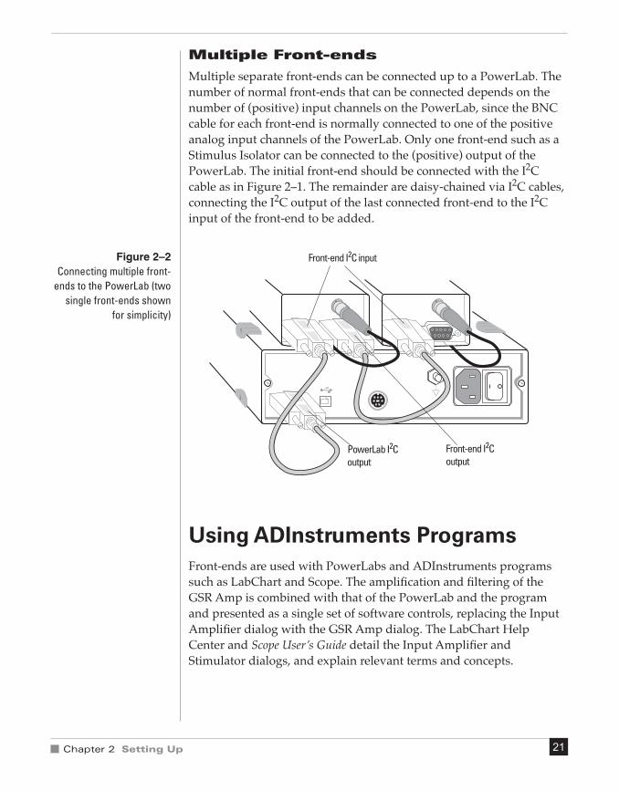
Multiple separate front-ends can be connected up to a PowerLab. The number of normal front-ends that can be connected depends on the number of (positive) input channels on the PowerLab, since the BNC cable for each front-end is normally connected to one of the positive analog input channels of the PowerLab. Only one front-end such as a Stimulus Isolator can be connected to the (positive) output of the PowerLab. The initial front-end should be connected with the I2C cable as in Figure 2–1. The remainder are daisy-chained via I2C cables, connecting the I2C output of the last connected front-end to the I2C input of the front-end to be added.
Using ADInstruments ProgramsFront-ends are used with PowerLabs and ADInstruments programs such as LabChart and Scope. The amplification and filtering of the GSR Amp is combined with that of the PowerLab and the program and presented as a single set of software controls, replacing the Input Amplifier dialog with the GSR Amp dialog. The LabChart Help Center and Scope User’s Guide detail the Input Amplifier and Stimulator dialogs, and explain relevant terms and concepts.
PowerLab I2C output
Front-end I2C input
Front-end I2C output
Figure 2–2Connecting multiple front-
ends to the PowerLab (two
single front-ends shown
for simplicity)
GSR Amp Owner’s Guide22
The Front-end Driver
A driver is a piece of software the computer uses to drive a peripheral device. In order for a front-end to be recognized by ADInstruments applications, the appropriate front-end driver must be present. The BP/GSR (Macintosh) or BP GSR Amp (Windows) front-end driver is used with the GSR Amp. Front-end drivers are installed when ADInstruments applications are installed on the computer. To replace the drivers, you should reinstall the ADInstruments software.
The Front-end Self-test
Once the front-end is properly connected to the PowerLab, and the proper software is installed on the computer, a quick check can be performed on the front-end. To perform the self-test:
1. Turn on the PowerLab and check that it is working properly, as described in the owner’s guide that was supplied with it.
2. Once the PowerLab is ready, open either LabChart or Scope. While the application is opening, watch the GSR Amp’s Status indicator. On initialization, the indicator flashes briefly and then remains lit.
If the indicator lights correctly, the front-end has been found by the PowerLab and is working properly. If the indicator doesn’t light, check your cable connections and repeat the start-up procedure.
Software Behavior
When a GSR Amp is properly connected to a channel, the Input Amplifier… menu command is replaced by GSR Amp… for the input channel to which it is connected. If the application fails to find a front-end connected, the normal text remains. If you were expecting a connected front-end and see the normal text, you should quit the program, turn the PowerLab off and check the connections. Then restart the PowerLab and the application.
The documentation for LabChart and Scope does not cover front-end-specific features. These features are described in detail here for LabChart. Differences between LabChart and Scope should be fairly obvious from perusing the Scope User’s Guide. For the most part, dialogs for the different application programs are much the same.
Note: you cannot start sampling in LabChart and Scope if a connected GSR Amp is not zeroed. Therefore, the first step is to zero the device.

Chapter 2 Setting Up 23
The GSR Amp
The GSR Amp dialog allows software control of the combined options from the circuitry of the PowerLab and GSR Amp. The signal present at a channel’s input is displayed so you can see the effects of changing the settings. The GSR Amp is pre-calibrated and measures skin conductivity directly in μS (microsiemens). Once the GSR Amp is zeroed and settings have been changed, click OK to apply them.
The GSR Amp dialog appears when you choose GSR Amp… from a Channel Function pop-up menu (or click GSR Amp… in the Input Settings column in the Channel Settings dialog). To set up many channels quickly, click the arrows by the dialog title, or press the left or right arrow keys on the keyboard, to move to the equivalent dialogs for adjacent channels. This skips channels that are turned off. The channel number is shown next to the arrows, and the channel title (if any) is shown on the vertical Amplitude axis.
Signal Display
The input signal is displayed so you can see the effect of changing the settings — no data are recorded while you adjust the settings. Slowly changing waveforms are represented quite accurately, whereas quickly changing signals are displayed as a solid dark area showing only the envelope (shape) of the signal formed by the minimum and maximum recorded values. The average signal value is shown above the display area.
You can stop the signal scrolling by clicking the Pause button at the bottom left (Macintosh) or top right (Windows) of the data display area. This changes to the Scroll button on the Macintosh. Click the Scroll button to start scrolling again.
Shift and stretch the vertical Amplitude axis, by clicking and dragging it in various ways, to make the best use of the available display area. It functions the same as the Amplitude axis of the Chart window, controls are identical, and any change is applied to the Chart window.
Setting the Range
The Range pop-up menu lets you select the input range or sensitivity of the channel. Changing the range in the GSR Amp dialog is equivalent to changing it in the Chart Window. There are six ranges: 1, 2, 4, 10, 20 and 40 μS.

GSR Amp Owner’s Guide24
On a Macintosh, Show Range Axis in the Scale pop-up menu displays the range axis on the right of the display area. The Compression buttons adjust the horizontal axis of the data display area.
Signal amplitude Pause and Scroll buttons
Range pop-up menu
Amplitude axis
Signal amplitude
Pause/Scroll button
Range pop-up menuAmplitude axis
Compression buttons
Figure 2–3The GSR Amp dialog for
Macintosh (before zeroing)
Figure 2–4The GSR Amp dialog for
Windows (after an
Open Circuit Zero)
Chapter 2 Setting Up 25
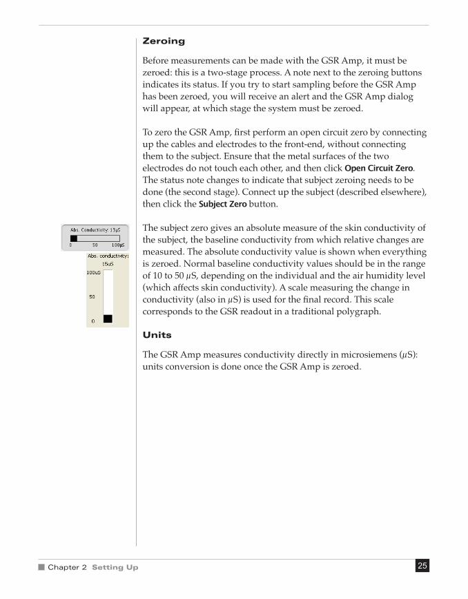
Zeroing
Before measurements can be made with the GSR Amp, it must be zeroed: this is a two-stage process. A note next to the zeroing buttons indicates its status. If you try to start sampling before the GSR Amp has been zeroed, you will receive an alert and the GSR Amp dialog will appear, at which stage the system must be zeroed.
To zero the GSR Amp, first perform an open circuit zero by connecting up the cables and electrodes to the front-end, without connecting them to the subject. Ensure that the metal surfaces of the two electrodes do not touch each other, and then click Open Circuit Zero. The status note changes to indicate that subject zeroing needs to be done (the second stage). Connect up the subject (described elsewhere), then click the Subject Zero button.
The subject zero gives an absolute measure of the skin conductivity of the subject, the baseline conductivity from which relative changes are measured. The absolute conductivity value is shown when everything is zeroed. Normal baseline conductivity values should be in the range of 10 to 50 μS, depending on the individual and the air humidity level (which affects skin conductivity). A scale measuring the change in conductivity (also in μS) is used for the final record. This scale corresponds to the GSR readout in a traditional polygraph.
Units
The GSR Amp measures conductivity directly in microsiemens (μS): units conversion is done once the GSR Amp is zeroed.

GSR Amp Owner’s Guide26

AA P P E N D I X
Appendix A Technical Aspects 27
This appendix describes some of the important technical aspects of the
GSR Amp to give some insight into how it works. You do not need to
know the material here to use a front-end. It is likely to be of special
interest to the technically minded, indicating what a front-end can and
cannot do, and its suitability for particular purposes. (You should not
use it as a service manual: user modification of the equipment voids
your rights under warranty.)
The GSR Amp and other ADInstruments front-ends have been
designed to integrate fully into the PowerLab system. Each requires
connection to the PowerLab via a special communications connector
called the I2C (eye-squared-sea) bus, and a BNC connector.
A TechnicalAspects

GSR Amp Owner’s Guide28
GSR Amp OperationThe GSR Amp is essentially an extension of the PowerLab’s analog input. The GSR Amp provides:
• full electrical isolation from power-line (mains) circuitry to guarantee subject safety
• measurement of the Féré effect, a general measure of autonomic nervous system activity, directly in SI conductance units (siemens)
• low, constant-voltage AC excitation (22 mVrms @ 75 Hz) allows enhanced safety and the use of dry electrodes, with no special electrolytes needed
• measurement of absolute conductivity up to 100 μS (microsiemens).
The internal functions of the GSR Amp are controlled from the PowerLab through the I2C bus, which also supplies power to the GSR Amp. The front-end is also connected to an analog input channel of the PowerLab via a BNC-to-BNC cable, through which the signal is sent. The overall operation of the GSR Amp can be better understood by referring to Figure A–1.
The 75 Hz oscillator supplies a near-square wave, low-impedance, low-voltage signal (22 mVrms) to an electrode on a finger of the subject. If the skin has measurable conductance (rather than as an insulator), then current flows, from an electrode on another finger of the subject, into the very low impedance input of the transimpedance amplifier.
75 Hz Oscillator
Isolation Barrier
8 MHz Crystal
400 Hz Power
Oscillator
Synchronous Rectifier
Micro Processor Controller
12-bit Offsetting
DAC
1 Hz 2nd Order Low-pass filter
× 50
× 1
–
+
Sig
nal
Mod
ulat
or
Isolated Power Supply
Sync
hron
ous
Rect
ifier
I2C Output
I2C Input
Signal Output
Transimpedance Amplifier
Isolation Transformers
Status Indicator
Subject Connections
Figure A–1Block diagram of the
GSR Amp

Appendix A Technical Aspects 29
The transimpedance amplifier converts current to voltage. The current will change as the autonomic reflexes change the skin’s conductivity. The resulting signal is passed through a synchronous rectifier to obtain a DC voltage proportional to skin conductance, then via a modulator to produce a 400 Hz AC signal suitable for passing across the isolation barrier (providing electrical protection for the subject).
On the other side of the isolation barrier, the AC signal is multiplied then synchronously rectified, restoring a DC voltage proportional to skin conductance. To reduce noise in the rectified signal, it is passed through a 1 Hz, second-order, low-pass filter, which leaves the general signal trends unchanged, but removes higher-frequency fluctuations. The signal at this point consists of the overall (baseline) skin conductivity plus a component representing the Féré effect changes, or galvanic skin response (GSR).
A precision ×1 instrumentation amplifier compares the signal with the output of the 12-bit digital-to-analog converter (DAC). The DAC provides an exact offset voltage for zeroing and offsetting of the synchronously demodulated and filtered signal. This ensures maximum signal-to-noise ratio, good zeroing resolution, and maximum resolution in the displayed signal. The DAC removes the constant baseline, allowing just the fluctuations to be observed.
The control for offsetting and zeroing functions in the GSR Amp is provided by an on-board microcontroller, which also communicates with the PowerLab over the I2C bus.

GSR Amp Owner’s Guide30

Appendix B Troubleshooting 31
BA P P E N D I X
This appendix describes most of the common problems that can occur
when using the GSR Amp with your PowerLab recording unit. It
covers how these problems are caused, and what you can do to
alleviate them. If the solutions here do not work, earlier chapters, the
LabChart Help Center, and the guide to your PowerLab may contain
possible remedies. If none of the solutions here or elsewhere are of
help, then consult your ADInstruments representative.
Most of the problems that users encounter are connection problems,
and can usually be fixed by checking connections and starting up the
hardware and software again. Very rarely will there be an actual
problem with the front-end or the PowerLab itself.
B Troubleshooting

GSR Amp Owner’s Guide32
ProblemsThe status indicators fail to light when the software is started, or the front-end commands and so on do not appear where they should
The I2C cable or the BNC-to-BNC cable from the front-end to the PowerLab is not connected, has been connected incorrectly (to the wrong input or output, for instance), or is loose.
• Turn everything off. Check to see that all cables are firmly seated and screwed in. BNC cables from the GSR Amp must be connected to a positive input on the PowerLab. Make sure the input is the same channel from which you expect to use the front-end in the software. After checking connections, restart the PowerLab and application to see if this has fixed the problem.
You are using an early version of LabChart or Scope.
• Upgrade to the latest version of the software. Contact your ADInstruments representative for information.
The BNC or I2C cable is faulty.
• Replace the cable and try again. Immediately label all cables proved faulty so that you don’t use them again by accident.
The front-end is faulty.
• This is the least likely event. If the front-end will not work properly after the previous measures, then try using it on another PowerLab. If the same problems recur with a second PowerLab, the front-end may be faulty. Contact your ADInstruments representative to arrange for repairs.
On starting up the software, an alert indicates that there is a problem with the front-end or driver
The correct BP/GSR drivers are not installed on your computer (they should be in the Essential Files folder in the LabChart or Scope folder).
• Reinstall the software.

Appendix B Troubleshooting 33
You are using an early version of LabChart or Scope.
• Upgrade to the latest version of the software. Contact your ADInstruments representative for information.
The BNC or I2C cable is faulty.
• Replace the cable and try again. Immediately label all cables proved faulty so that you don’t use them again by accident.
The front-end is faulty.
• This is the least likely event. If the front-end will not work properly after the previous measures, then try using it on another PowerLab. If the same problems recur with a second PowerLab, the front-end may be faulty. Contact your ADInstruments representative to arrange for repairs.
Some software settings don’t resemble those in this guide
You are using an early version of the front-end driver, or of LabChart or Scope. Some changes may have been made since then.
• Upgrade to the latest version of the software. Contact your ADInstruments representative for information.

GSR Amp Owner’s Guide34

Appendix C Specifications 35
CA P P E N D I X
Input
Connection type: 2× 4 mm shrouded banana plugs to custom cable. Two dry, bright-plated, bipolar electrodes with Velcro™ attachment strap suitable for adult fingers.
Excitation: Constant-voltage AC excitation(22 mVrms @ 75 Hz)
Current density: ≤ 0.5 μA cm–2
Safety: Approved to IEC601-1 BF (body protection) standard
Input isolation: Transformer isolation (AC bridge operation)
Isolation rating: 4000 V ACrms for 1 minute
Amplification ranges: 1 to 40 μS full scale in 6 steps(combined PowerLab and GSR Amp)
0–40 μS0–20 μS0–10 μS0–4 μS0–2 μS0–1 μS
C Specifications

GSR Amp Owner’s Guide36
Frequency response: –3 dB at 1 Hz
Accuracy: ±5%
Input leakage current: < 3 μArms at 240V, 50 Hz < 2 μArms at 120V, 60 Hz
Zeroing and offset: Automatic software-controlled fast zeroing, controlled by internal 12-bit DAC; resolution = ±0.2 μS
Output
Signal: ±2.0 V full scale: suitable for PowerLab
Control Port
I2C port: Provides control and power. Interface communications rate of ~50 kbits/s.
Physical Configuration
Dimensions (h × w × d): 50 mm × 76 mm × 260 mm(1.97" × 3.0" × 10.2")
Weight: 750 g (1 lb 10.5 oz)
Power requirements: 2.5 W max
Operating conditions: 5–35 °C0–90% humidity (non-condensing)
ADInstruments reserves the right to alter these specifications at any time.

Index 37
A
ADInstruments programs 21–25analog output 17
B
back panel 16–17block diagram 28
C
checking the front-end 14cleaning 10connections
multiple front-ends 21single front-end 20to the PowerLab 20–21
D
differential inputs 17, 20
F
front panel 15–16front-end driver 22, 32front-ends, general 14–15
G
GSR Amp software 23–25
I
I2C bus 14, 16, 27, 28
L
LabChart 21
M
maintenance 10measuring GSR 17–18
P
PowerLab system 14problems and solutions 32–33
S
Safety Notes 5–11Scope 21self-test 22Signal Output 17single-ended inputs 20status indicator 16storage 10
T
technical specificationsGSR Amp 35–36
U
user modification 27using ADInstruments programs 21–25using this guide 14
Index

GSR Amp Owner’s Guide38
Z
zeroing the GSR Amp 25