gst111020268e emc report - hkvstar.com · report reference no.: gst111020268e issued: oct. 21, 2011...
TRANSCRIPT


Report Reference No.: GST111020268E
Issued: Oct. 21, 2011 Revised: None
Page 2 of 46
TABLE OF CONTENTS
1. GENERAL INFORMATION ....................................................................................................................................5 1.1 PRODUCT DESCRIPTION FOR EQUIPMENT UNDER TEST (EUT)..........................................................................5 1.2 OBJECTIVE............................................................................................................................................................5 1.3 RELATED SUBMITTAL(S)/GRANT(S) .....................................................................................................................5 1.4 TEST METHODOLOGY ...........................................................................................................................................5 1.5 TEST FACILITY ......................................................................................................................................................5
2. SYSTEM TEST CONFIGURATION ......................................................................................................................6 2.1 DESCRIPTION OF TEST CONFIGURATION .............................................................................................................6 2.2 EQUIPMENT MODIFICATIONS ................................................................................................................................6 2.3 LOCAL SUPPORT EQUIPMENT LIST AND DETAILS ................................................................................................6 2.4 LOCAL TEST EQUIPMENT LIST AND DETAILS .......................................................................................................6 2.5 CONFIGURATION OF TEST SETUP ........................................................................................................................7 2.6 BLOCK DIAGRAM OF TEST SETUP........................................................................................................................7
3. CONDUCTED EMISSIONS ....................................................................................................................................8 3.1 MEASUREMENT UNCERTAINTY.............................................................................................................................8 3.2 EUT SETUP ..........................................................................................................................................................8 3.3 EMI TEST RECEIVER SETUP ................................................................................................................................9 3.4 TEST PROCEDURE................................................................................................................................................9 3.5 TEST RESULTS SUMMARY....................................................................................................................................9 3.6 TEST DATA .........................................................................................................................................................10
4. RADIATED EMISSIONS .......................................................................................................................................11 4.1 MEASUREMENT UNCERTAINTY...........................................................................................................................11 4.2 TEST SYSTEM SETUP .........................................................................................................................................11 4.3 EMI TEST RECEIVER SETUP ..............................................................................................................................12 4.4 TEST PROCEDURE..............................................................................................................................................12 4.5 CORRECTED AMPLITUDE & MARGIN CALCULATION ..........................................................................................12 4.6 TEST RESULTS SUMMARY..................................................................................................................................12 4.7 TEST DATA .........................................................................................................................................................13
5. HARMONIC CURRENT EMISSIONS .................................................................................................................14 5.1 TEST SYSTEM SETUP .........................................................................................................................................14 5.2 TEST STANDARD.................................................................................................................................................14 5.3 TEST PRODUCT CLASS:....................................................................................................................................14 5.4 TEST DATA .........................................................................................................................................................15
6. VOLTAGE FLUCTUATION AND FLICKER ......................................................................................................19 6.1 TEST SYSTEM SETUP .........................................................................................................................................19 6.2 TEST STANDARD.................................................................................................................................................19 6.3 TEST DATA .........................................................................................................................................................20
7. RF ELECTROMAGNETIC FIELD (80 MHz to 1000 MHz and 1400 MHz to 2700MHz) ....................................21 7.1 TEST SYSTEM SETUP .........................................................................................................................................21 7.2 TEST STANDARD.................................................................................................................................................21 7.3 TEST PROCEDURE..............................................................................................................................................22 7.4 TEST DATA AND SETUP PHOTO .........................................................................................................................22
8. ELECTROSTATIC DISCHARGE.........................................................................................................................23 8.1 TEST SYSTEM SETUP .........................................................................................................................................23 8.2 TEST STANDARD.................................................................................................................................................23 8.3 TEST PROCEDURE..............................................................................................................................................24 8.4 TEST DATA .........................................................................................................................................................24

Report Reference No.: GST111020268E
Issued: Oct. 21, 2011 Revised: None
Page 3 of 46
9. ELECTRICAL FAST TRANSIENT IMMUNITY..................................................................................................25 9.1 TEST SYSTEM SETUP .........................................................................................................................................25 9.2 TEST STANDARD.................................................................................................................................................25 9.3 TEST PROCEDURE..............................................................................................................................................26 9.4 TEST DATA .........................................................................................................................................................26
10. RF COMMON MODE...........................................................................................................................................27 10.1 TEST SETUP .....................................................................................................................................................27 10.2TEST STANDARD ...............................................................................................................................................27 10.3 TEST PROCEDURE............................................................................................................................................27 10.4 TEST DATA .......................................................................................................................................................28
11. SURGES, LINE TO LINE AND LINE TO GROUND.......................................................................................29 11.1 TEST SYSTEM SETUP.......................................................................................................................................29 11.2 TEST STANDARD ..............................................................................................................................................29 11.3 TEST PROCEDURE............................................................................................................................................30 11.4 TEST DATA .......................................................................................................................................................30
12. VOLTAGE DIPS/ INTERRUPTIONS IMMUNITY TEST.................................................................................31 12.1 TEST SETUP .....................................................................................................................................................31 12.2 TEST STANDARD ..............................................................................................................................................31 12.3 TEST PROCEDURE............................................................................................................................................31 12.4 TEST DATA .......................................................................................................................................................32


Report Reference No.: GST111020268E
Issued: Oct. 21, 2011 Revised: None
Page 5 of 46
1. GENERAL INFORMATION
1.1 Product Description for Equipment under Test (EUT) The NNB TECHNOLOGY LIMITED product, model number: T4, T6, G40, G70, G71, G72, G73, G74, G75, G76, G77, G78, G79. or the "EUT" as referred to in this report is a GSM Alarm, rated input voltage: DC 12V/1000 mA by Adapger input AC 100-240V~ 50/60Hz. 1.2 Objective The following test report is prepared on behalf of Global-Standard Testing Service Co., Ltd. in accordance with ETSI EN 301 489-1 V1.8.1 (2008-04) Plus Provisions of ETSI EN 301 489-7 V1.3.1 (2005-11), Electromagnetic compatibility and Radio spectrum Matters (ERM); Electro Magnetic Compatibility (EMC) standard for radio equipment and services; Part 7: Specific conditions for mobile and portable redio and ancillary equipment of digital cellular radio telecommunications systems (EHSM and DCS). The objective of the manufacturer is to determine compliance with ETSI EN 301 489-1 V1.8.1 (2008-04) Plus Provisions of ETSI EN 301 489-7 V1.3.1 (2005-11). 1.3 Related Submittal(s)/Grant(s) No Related Submittal(s). 1.4 Test Methodology All measurements contained in this report were conducted with ETSI EN 301 489-1 V1.8.1 (2008-04). 1.5 Test Facility The Test site used by Global Unite Technology Co., Ltd. to collect test data is located in 2nd 2 floor, Block No. 2, Lao Dong Industrial Zone, Xixiang Road, Baoan District, Shenzhen, China. Test site at Global Unite Technology Co., Ltd. has been fully described in reports submitted to the Federal Communication Commission (FCC). The details of these reports have been found to be in compliance with the requirements of Section 2.948 of the FCC Rules

Report Reference No.: GST111020268E
Issued: Oct. 21, 2011 Revised: None
Page 6 of 46
2. SYSTEM TEST CONFIGURATION
2.1 Description of Test Configuration The system was configured for testing in a typical fashion (as normally used by a typical user). 2.2 Equipment Modifications No modifications were made to the EUT. 2.3 Local Support Equipment List and Details
Manufacturer Description Model Serial Number FCC ID
R & S Universal Radio
commutation tester CMU200 1100 0008.02 DoC
2.4 Local Test Equipment List and Details
Manufacturer Description Model Serial
Number Calibration
Date Calibration Due Date
Com-Power L.I.S.N. LI-200 12005 N/A N/A
Rohde & Schwarz EMI Test Receiver ESCS30 830245/006 2011-04-27 2012-04-26
Rohde & Schwarz L.I.S.N. ESH2-Z5 892107/021 2011-04-27 2012-04-26
Sunol Sciences Bilog Antenna JB1 A040904-2 2011-04-27 2012-04-26
EM Test Harmonic/Flicker
Analyzer DPA500 0501-10 2011-04-27 2012-04-26
EM Test Digital power
analyer DPA 500N
V0939105176
2011-04-27 2012-04-26
EM Test ESD Tester Dito 302105 2011-04-27 2012-04-26
Sunol Sciences Horn Antenna DRH-118 A052604 2011-04-27 2012-04-26
EM Test Ultra Compact
Generator UCS500-M4 0801-15 2011-04-27 2012-04-26
EM Test Auto-transformer MV2616 0403-16 2011-04-27 2012-04-26
EM Test CDN T2 1101-07 2011-04-27 2012-04-26
EM Test CDN M3 1201-05 2011-04-27 2012-04-26
EM Test C/S Tester CWS500 303277 2011-04-27 2012-04-26
EM Test Attenuator 6dB 303282 2011-04-27 2012-04-26
FCC Bulk Current
Injection Probe F-120-9A 303284 2011-04-27 2012-04-26
EM Test Auto-transformer MV2616 0403-16 2011-04-27 2012-04-26
EM Test Ultra Compact
Generator UCS500-M4 0801-15 2011-04-27 2012-04-26
Report Reference No.: GST111020268E
Issued: Oct. 21, 2011 Revised: None
Page 7 of 46
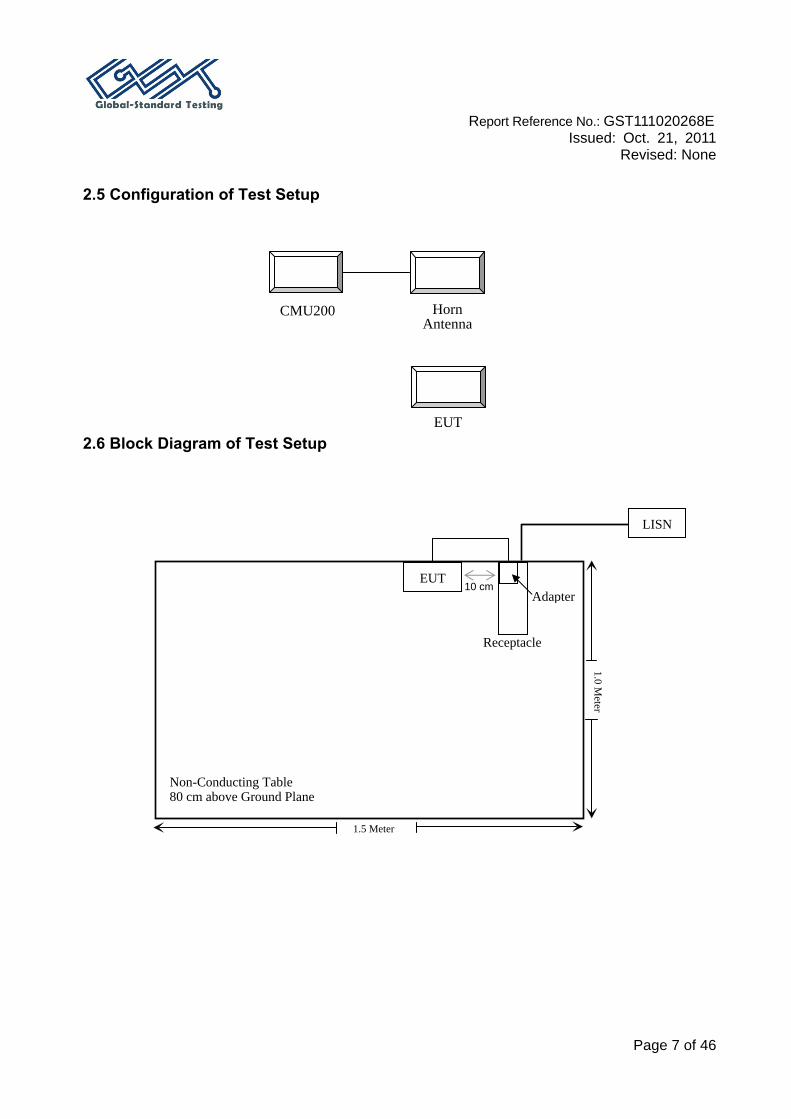
2.5 Configuration of Test Setup 2.6 Block Diagram of Test Setup
1.5 Meter
1.0 Meter
Non-Conducting Table 80 cm above Ground Plane
EUT 10 cm
Adapter
Receptacle
LISN
Horn Antenna
EUT
CMU200

Report Reference No.: GST111020268E
Issued: Oct. 21, 2011 Revised: None
Page 8 of 46
3. CONDUCTED EMISSIONS
3.1 Measurement Uncertainty All measurements involve certain levels of uncertainties, especially in field of EMC. The factors contributing to uncertainties are spectrum analyzer, cable loss, and LISN. 3.2 EUT Setup The setup of EUT is according with per ETSI EN 301 489-1 measurement procedure. The specification used was with the ETSI EN 301 489-1 limits. The external I/O cables were draped along the test table and formed a bundle 30 to 40 cm long in the middle. The spacing between the peripherals was 10 cm. The adapter was connected to a 230 VAC/50 Hz power source.
Report Reference No.: GST111020268E
Issued: Oct. 21, 2011 Revised: None
Page 9 of 46
3.3 EMI Test Receiver Setup The EMI test receiver was set to investigate the spectrum from 150 kHz to 30 MHz. During the conducted emission test, the EMI test receiver was set with the following configurations:
Frequency Range IFBW 150 kHz – 30 MHz 9 kHz
3.4 Test Procedure During the conducted emission test, the adapter was connected to the outlet of the LISN. Maximizing procedure was performed on the six (6) highest emissions of the EUT. All data was recorded in the Quasi-peak and average detection mode. 3.5 Test Results Summary According to the recorded data in following table, the EUT complied with the ETSI EN 301 489-1, with the worst margin reading of:
19.10 dB at 28.820 MHz in the Neutral conductor mode

Report Reference No.: GST111020268E
Issued: Oct. 21, 2011 Revised: None
Page 10 of 46
3.6 Test Data
Test Mode: GSM 900 Traffic mode (worst case)
Conducted Emissions EN 301 489-7
Frequency (MHz)
Amplitude (dBμV)
Detector (QP/AV)
Conductor (Line/Neutral)
Limit (dBμV)
Margin (dB)
28.820 30.90 AV Neutral 50.00 19.10 28.565 40.70 QP Neutral 60.00 19.30 13.415 33.50 QP Neutral 60.00 26.50 13.375 22.10 AV Neutral 50.00 27.90 2.810 16.10 AV Neutral 46.00 29.90 16.460 29.70 QP Neutral 60.00 30.30 0.535 23.80 QP Neutral 56.00 32.20 2.810 23.80 QP Neutral 56.00 32.20 16.315 17.60 AV Neutral 50.00 32.40 0.400 25.00 QP Neutral 57.85 32.85 0.405 24.40 QP Line 57.75 33.35 0.535 20.40 QP Line 56.00 35.60 0.400 11.60 AV Neutral 47.85 36.25 0.335 12.50 AV Line 49.33 36.83 0.535 9.10 AV Line 46.00 36.90 0.270 14.10 AV Line 51.12 37.02 27.385 22.70 QP Line 60.00 37.30 0.535 8.60 AV Neutral 46.00 37.40 13.805 22.20 QP Line 60.00 37.80 0.335 21.20 QP Line 59.33 38.13 13.870 11.10 AV Line 50.00 38.90 0.270 22.20 QP Line 61.12 38.92 27.665 10.80 AV Line 50.00 39.20 0.410 6.30 AV Line 47.75 41.45
Report Reference No.: GST111020268E
Issued: Oct. 21, 2011 Revised: None
Page 11 of 46
4. RADIATED EMISSIONS
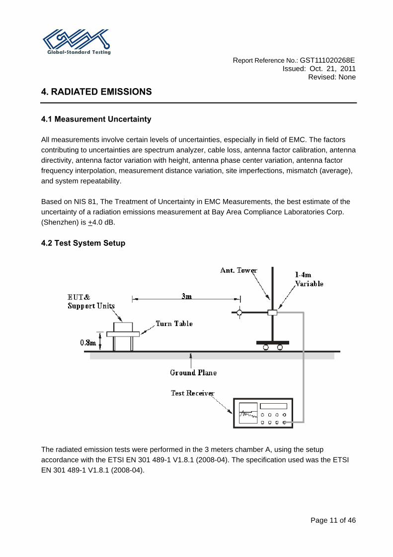
4.1 Measurement Uncertainty All measurements involve certain levels of uncertainties, especially in field of EMC. The factors contributing to uncertainties are spectrum analyzer, cable loss, antenna factor calibration, antenna directivity, antenna factor variation with height, antenna phase center variation, antenna factor frequency interpolation, measurement distance variation, site imperfections, mismatch (average), and system repeatability. Based on NIS 81, The Treatment of Uncertainty in EMC Measurements, the best estimate of the uncertainty of a radiation emissions measurement at Bay Area Compliance Laboratories Corp. (Shenzhen) is +4.0 dB. 4.2 Test System Setup The radiated emission tests were performed in the 3 meters chamber A, using the setup accordance with the ETSI EN 301 489-1 V1.8.1 (2008-04). The specification used was the ETSI EN 301 489-1 V1.8.1 (2008-04).
Report Reference No.: GST111020268E
Issued: Oct. 21, 2011 Revised: None
Page 12 of 46
4.3 EMI Test Receiver Setup The system was investigated from 30 MHz to 1000 MHz. During the radiated emission test, the EMI test receiver Setup was set with the following configurations:
Frequency Range RBW VBW IFBW 30 MHz – 1000 MHz 100 kHz 300 kHz 120 kHz
4.4 Test Procedure For the radiated emissions test, the adapter was connected to AC floor outlet. Maximizing procedure was performed on the highest emissions to ensure that the EUT complied with all installation combinations. All data was recorded in the Quasi-peak detection mode. 4.5 Corrected Amplitude & Margin Calculation The Corrected Amplitude is calculated by adding the Antenna Factor and Cable Loss, and subtracting the Amplifier Gain from the Meter reading. The basic equation is as follows:
Corr. Amp. =Meter Reading + Antenna Factor+ Cable Loss - Amplifier Gain The “Margin” column of the following data tables indicates the degree of compliance with the applicable limit. For example, a margin of -7dB means the emission is 7dB below the limit. The equation for margin calculation is as follows:
Margin = Limit. – Corrected Amp. 4.6 Test Results Summary According to the data in the following table, the EUT complied with the ETSI EN 301 489-1 V1.8.1 (2008-04), with the worst margin reading of:
Below 1 GHz: 7.4 dB at 183.088250 MHz in the Horizontal polarization Above 1 GHz: 19.4 dB at 1140.714750 MHz in the Vertical polarization

Report Reference No.: GST111020268E
Issued: Oct. 21, 2011 Revised: None
Page 13 of 46
4.7 Test Data
Test Mode: traffic mode
Frequency (MHz)
Quasi-Peak
(dBμV/m)
Antenna Height (cm)
AntennaPolarity
Turntable Position
(deg)
Correction Factor (dB)
Limit (dBμV/m)
Margin(dB)
183.088250 32.6 181.0 H 68.0 -15.9 40.0 7.4 140.714750 28.5 101.0 V 309.0 -14.5 40.0 11.5 486.978250 35.4 101.0 H 109.0 -10.6 47.0 11.6 208.021750 28.2 100.0 V 124.0 -15.2 40.0 11.8 369.506000 35.2 107.0 H 352.0 -13.0 47.0 11.8 707.823000 35.2 264.0 V 260.0 -4.4 47.0 11.8

Report Reference No.: GST111020268E
Issued: Oct. 21, 2011 Revised: None
Page 14 of 46
5. HARMONIC CURRENT EMISSIONS
5.1 Test System Setup
5.2 Test Standard
EN 61000-3-2: 2006 5.3 Test product class:
Class A: - Balanced three-phase equipment - Household appliances excluding equipment identified as class D - Tools excluding portable tools - Dimmers for incandescent lamps
- Audio equipment
Class B: - Portable tools - Arc welding equipment, which is not professional equipment
Class C: - Lighting equipment Class D: Equipment having a specified power less than or equal to 600w, of the
following type: - Personal computer and personal computer monitors - Television receivers
Application of limits: The average values for the individual harmonic currents, taken over the entire test observation period shall be less than or equal to the applicable limits. For each harmonic order, all 1,5 s
AC Mains
AC Source
EUT System
Wooden Table 0.8m
Analyzer

Report Reference No.: GST111020268E
Issued: Oct. 21, 2011 Revised: None
Page 15 of 46
smoothed r.m.s. harmonic current values, shall be either: a) less than or equal to 150 % of the applicable limits, or b) less than or equal to 200 % of the applicable limits under the following conditions, which apply all together: 1) the EUT belongs to Class C for harmonics; 2) the excursion beyond 150 % of the applicable limits lasts less than 10 % of the test observation period or in total 10 min (within the test observation period), whichever is smaller, and 3) the average value of the harmonic current, taken over the entire test observation period, is less than 90 % of the applicable limits. Harmonic currents less than 0,6 % of the input current measured under the test conditions, or less than 5 mA, whichever is greater, are disregarded. For the 21st and higher odd order harmonics, the average value obtained for each individual odd harmonic over the full observation period, calculated from the 1,5 s smoothed r.m.s. values , may exceed the applicable limits by 50 % provided that the following conditions are met: * the measured partial odd harmonic current does not exceed the partial odd harmonic current which can be calculated from the applicable limits; * all 1,5 s smoothed r.m.s. individual harmonic current values shall be less than or equal to 150 % of the applicable limits. 5.4 Test Data
Date of test: 11:01 2010-08-12
Measurement file name: Harmonics_3_2_A14.rsd
Standard used: EN 61000-3-2
Observation time: 10s
Windows width: 10 periods - (EN/IEC 61000-4-7 Edition 2002)
Test mode GSM\DCS Communicating
Average harmonic current results
Hn Ieff [A] % of Limit Limit [A] Result 1 12.197E-3 2 1.109E-3 0.114 972.00E-3 PASS 3 12.156E-3 0.587 2.07 PASS 4 802.913E-6 0.207 387.00E-3 PASS 5 11.444E-3 1.115 1.03 PASS 6 770.234E-6 0.285 270.00E-3 PASS 7 10.913E-3 1.575 693.00E-3 PASS 8 674.729E-6 0.326 207.00E-3 PASS
Report Reference No.: GST111020268E
Issued: Oct. 21, 2011 Revised: None
Page 16 of 46
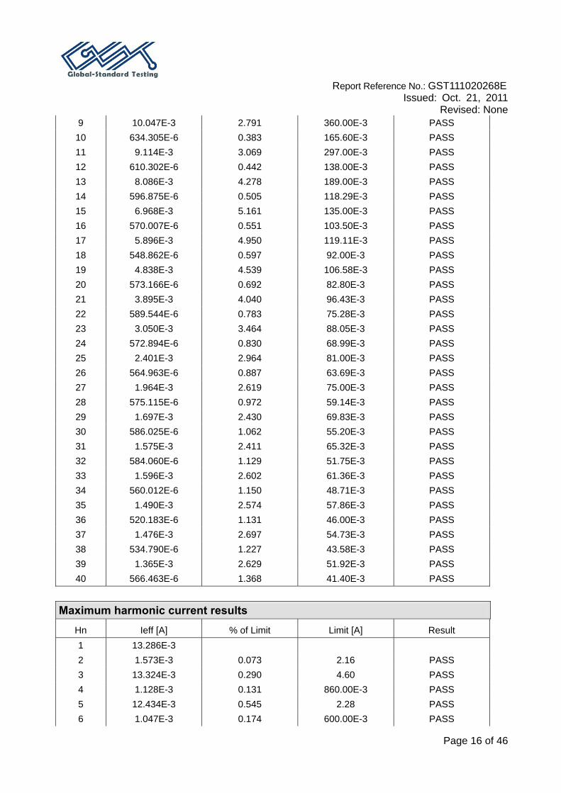
9 10.047E-3 2.791 360.00E-3 PASS 10 634.305E-6 0.383 165.60E-3 PASS 11 9.114E-3 3.069 297.00E-3 PASS 12 610.302E-6 0.442 138.00E-3 PASS 13 8.086E-3 4.278 189.00E-3 PASS 14 596.875E-6 0.505 118.29E-3 PASS 15 6.968E-3 5.161 135.00E-3 PASS 16 570.007E-6 0.551 103.50E-3 PASS 17 5.896E-3 4.950 119.11E-3 PASS 18 548.862E-6 0.597 92.00E-3 PASS 19 4.838E-3 4.539 106.58E-3 PASS 20 573.166E-6 0.692 82.80E-3 PASS 21 3.895E-3 4.040 96.43E-3 PASS 22 589.544E-6 0.783 75.28E-3 PASS 23 3.050E-3 3.464 88.05E-3 PASS 24 572.894E-6 0.830 68.99E-3 PASS 25 2.401E-3 2.964 81.00E-3 PASS 26 564.963E-6 0.887 63.69E-3 PASS 27 1.964E-3 2.619 75.00E-3 PASS 28 575.115E-6 0.972 59.14E-3 PASS 29 1.697E-3 2.430 69.83E-3 PASS 30 586.025E-6 1.062 55.20E-3 PASS 31 1.575E-3 2.411 65.32E-3 PASS 32 584.060E-6 1.129 51.75E-3 PASS 33 1.596E-3 2.602 61.36E-3 PASS 34 560.012E-6 1.150 48.71E-3 PASS 35 1.490E-3 2.574 57.86E-3 PASS 36 520.183E-6 1.131 46.00E-3 PASS 37 1.476E-3 2.697 54.73E-3 PASS 38 534.790E-6 1.227 43.58E-3 PASS 39 1.365E-3 2.629 51.92E-3 PASS 40 566.463E-6 1.368 41.40E-3 PASS
Maximum harmonic current results
Hn Ieff [A] % of Limit Limit [A] Result 1 13.286E-3 2 1.573E-3 0.073 2.16 PASS 3 13.324E-3 0.290 4.60 PASS 4 1.128E-3 0.131 860.00E-3 PASS 5 12.434E-3 0.545 2.28 PASS 6 1.047E-3 0.174 600.00E-3 PASS

Report Reference No.: GST111020268E
Issued: Oct. 21, 2011 Revised: None
Page 17 of 46
7 11.822E-3 0.768 1.54 PASS 8 944.190E-6 0.205 460.00E-3 PASS 9 10.907E-3 1.363 800.00E-3 PASS
10 858.552E-6 0.233 368.00E-3 PASS 11 9.922E-3 1.503 660.00E-3 PASS 12 845.660E-6 0.276 306.66E-3 PASS 13 8.833E-3 2.103 420.00E-3 PASS 14 816.200E-6 0.311 262.86E-3 PASS 15 7.605E-3 2.535 300.00E-3 PASS 16 761.459E-6 0.331 230.00E-3 PASS 17 6.463E-3 2.442 264.70E-3 PASS 18 697.566E-6 0.341 204.44E-3 PASS 19 5.302E-3 2.238 236.84E-3 PASS 20 750.944E-6 0.408 184.00E-3 PASS 21 4.278E-3 1.996 214.28E-3 PASS 22 738.183E-6 0.441 167.28E-3 PASS 23 3.340E-3 1.707 195.66E-3 PASS 24 723.866E-6 0.472 153.32E-3 PASS 25 2.622E-3 1.457 180.00E-3 PASS 26 720.189E-6 0.509 141.54E-3 PASS 27 2.155E-3 1.293 166.66E-3 PASS 28 711.370E-6 0.541 131.42E-3 PASS 29 1.848E-3 1.191 155.18E-3 PASS 30 750.730E-6 0.612 122.66E-3 PASS 31 1.699E-3 1.170 145.16E-3 PASS 32 762.579E-6 0.663 115.00E-3 PASS 33 1.746E-3 1.281 136.36E-3 PASS 34 711.253E-6 0.657 108.24E-3 PASS 35 1.675E-3 1.303 128.58E-3 PASS 36 655.435E-6 0.641 102.22E-3 PASS 37 1.660E-3 1.365 121.62E-3 PASS 38 679.659E-6 0.702 96.84E-3 PASS 39 1.532E-3 1.327 115.38E-3 PASS 40 721.709E-6 0.784 92.00E-3 PASS
Maximum harmonic voltage results
Hn Ueff [V] Ueff [%] Limit [%] Result 1 232.22 100.966 2 55.47E-3 0.024 0.2 PASS 3 56.74E-3 0.025 0.9 PASS 4 16.91E-3 0.007 0.2 PASS

Report Reference No.: GST111020268E
Issued: Oct. 21, 2011 Revised: None
Page 18 of 46
5 55.61E-3 0.024 0.4 PASS 6 10.32E-3 0.004 0.2 PASS 7 23.27E-3 0.010 0.3 PASS 8 13.51E-3 0.006 0.2 PASS 9 37.23E-3 0.016 0.2 PASS
10 15.10E-3 0.007 0.2 PASS 11 24.92E-3 0.011 0.1 PASS 12 18.38E-3 0.008 0.1 PASS 13 37.93E-3 0.016 0.1 PASS 14 13.18E-3 0.006 0.1 PASS 15 33.12E-3 0.014 0.1 PASS 16 11.03E-3 0.005 0.1 PASS 17 41.24E-3 0.018 0.1 PASS 18 11.17E-3 0.005 0.1 PASS 19 25.88E-3 0.011 0.1 PASS 20 13.36E-3 0.006 0.1 PASS 21 36.12E-3 0.016 0.1 PASS 22 10.80E-3 0.005 0.1 PASS 23 31.64E-3 0.014 0.1 PASS 24 10.18E-3 0.004 0.1 PASS 25 27.39E-3 0.012 0.1 PASS 26 10.45E-3 0.005 0.1 PASS 27 29.62E-3 0.013 0.1 PASS 28 11.68E-3 0.005 0.1 PASS 29 34.15E-3 0.015 0.1 PASS 30 10.73E-3 0.005 0.1 PASS 31 20.61E-3 0.009 0.1 PASS 32 11.09E-3 0.005 0.1 PASS 33 25.95E-3 0.011 0.1 PASS 34 9.98E-3 0.004 0.1 PASS 35 33.26E-3 0.014 0.1 PASS 36 10.91E-3 0.005 0.1 PASS 37 23.00E-3 0.010 0.1 PASS 38 9.52E-3 0.004 0.1 PASS 39 25.64E-3 0.011 0.1 PASS 40 10.79E-3 0.005 0.1 PASS

Report Reference No.: GST111020268E
Issued: Oct. 21, 2011 Revised: None
Page 19 of 46
6. VOLTAGE FLUCTUATION AND FLICKER
6.1 Test System Setup
6.2 Test Standard
EN 61000-3-3:2008 Flicker Test Limits: The limits shall be applicable to voltage fluctuations and flicker at the supply terminals of the equipment under test, measured or calculated according to clause 4 under test conditions described in clause 6 and annex A. Tests made to prove compliance with the limits are considered to be type tests. The following limits apply: – the value of Pst shall not be greater than 1,0; – the value of Plt shall not be greater than 0,65; – the value of d(t) during a voltage change shall not exceed 3,3 % for more than 500 ms; – the relative steady-state voltage change, dc, shall not exceed 3,3 %; – the maximum relative voltage change dmax, shall not exceed a) 4 % without additional conditions; b) 6 % for equipment which is: – switched manually, or – switched automatically more frequently than twice per day, and also has either a delayed restart (the delay being not less than a few tens of seconds), or manual restart, after a power supply interruption. NOTE: The cycling frequency will be further limited by the Pst and Plt limit. For example: a dmax of 6 % producing a rectangular voltage change characteristic twice per hour will give a Plt of about 0.65. c) 7 % for equipment which is – attended whilst in use (for example: hair dryers, vacuum cleaners, kitchen equipment such as mixers, garden equipment such as lawn mowers, portable tools such as electric drills), or – switched on automatically, or is intended to be switched on manually, no more than twice per day,
AC Mains
AC Source
EUT
Wooden Table
0.8 m
Analyzer
Adapter
Report Reference No.: GST111020268E
Issued: Oct. 21, 2011 Revised: None
Page 20 of 46
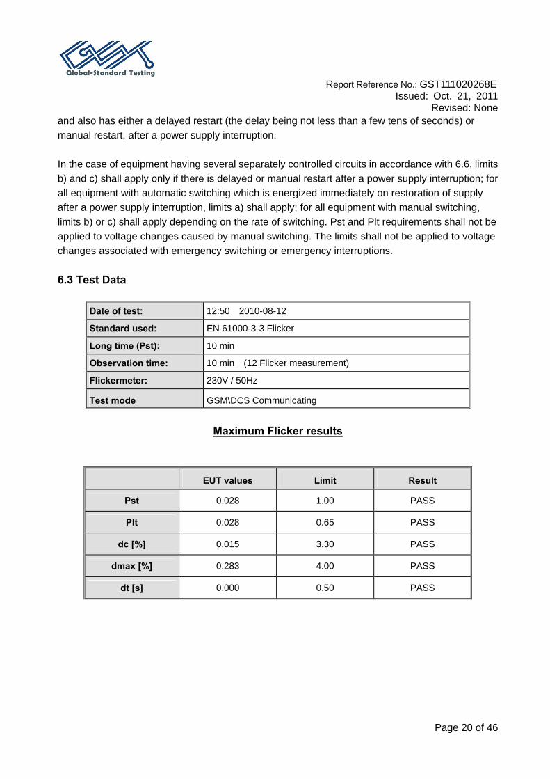
and also has either a delayed restart (the delay being not less than a few tens of seconds) or manual restart, after a power supply interruption. In the case of equipment having several separately controlled circuits in accordance with 6.6, limits b) and c) shall apply only if there is delayed or manual restart after a power supply interruption; for all equipment with automatic switching which is energized immediately on restoration of supply after a power supply interruption, limits a) shall apply; for all equipment with manual switching, limits b) or c) shall apply depending on the rate of switching. Pst and Plt requirements shall not be applied to voltage changes caused by manual switching. The limits shall not be applied to voltage changes associated with emergency switching or emergency interruptions. 6.3 Test Data
Date of test: 12:50 2010-08-12
Standard used: EN 61000-3-3 Flicker
Long time (Pst): 10 min
Observation time: 10 min (12 Flicker measurement)
Flickermeter: 230V / 50Hz
Test mode GSM\DCS Communicating
Maximum Flicker results
EUT values Limit Result
Pst 0.028 1.00 PASS
Plt 0.028 0.65 PASS
dc [%] 0.015 3.30 PASS
dmax [%] 0.283 4.00 PASS
dt [s] 0.000 0.50 PASS

Report Reference No.: GST111020268E
Issued: Oct. 21, 2011 Revised: None
Page 21 of 46
7. RF ELECTROMAGNETIC FIELD (80 MHz to 1000 MHz and 1400 MHz to
2700MHz)
7.1 Test System Setup Wooden table 7.2 Test Standard
ETSI EN 301 489-1 V1.8.1 / EN 61000-4-3:2006 Test Level 2 at 3V / m Test Levels and Performance Criterion
Test Level
Level Field Strength (V/m) 1. 1
2. 3
3. 10
X. Special
Performance Criterion: A
3 MetersEUT
System
0.8 Meter
Anechoic Chamber
Power Amp Signal Generator

Report Reference No.: GST111020268E
Issued: Oct. 21, 2011 Revised: None
Page 22 of 46
7.3 Test Procedure
The EUT and its simulators are placed on a turn table which is 0.8 meter above the ground. The EUT is set 3 meters away from the transmitting antenna which is mounted on an antenna tower. Both horizontal and vertical polarizations of the antenna are set on test. Each of the four sides of EUT must be faced this transmitting antenna and measured individually. All the scanning conditions are as follows: Condition of Test Remarks ---------------------------------------------- ----------------------------------
1. Field Strength 3 V/m (Test Level 2) 2. Radiated Signal Modulated 3. Scanning Frequency 80 - 1000 MHz and 1400-2700MHz 4. Sweeping time of radiated 0.0015 decade/s 5. Dwell Time 1 Sec.
7.4 Test Data and Setup Photo
Test Mode: GSM90 /DCS1800 traffic /idle mode
Front Side (3 V/m) Rear Side (3 V/m) Left Side (3 V/m) Right Side (3 V/m)Frequenc
y Range (MHz)
VERT HORI VERT HORI VERT HORI VERT HORI
80-1000 A A A A A A A A
1400-2700 A A A A A A A A

Report Reference No.: GST111020268E
Issued: Oct. 21, 2011 Revised: None
Page 23 of 46
8. ELECTROSTATIC DISCHARGE
8.1 Test System Setup
EN 61000-4-2 specifies that a tabletop EUT shall be placed on a non-conducting table which is 80 centimeters above a ground reference plane and that floor mounted equipment shall be placed on a insulating support approximately 10 centimeters above a ground plane. During the tests, the EUT is positioned over a ground reference plane in conformance with this requirement. For tabletop equipment, a 1.5 by 1.0-meter metal sheet (HCP) is placed on the table and connected to the ground plane via a metal strap with two 470 k Ohms resistors in series. The EUT and attached cables are isolated from this metal sheet by 0.5-millimeter thick insulating material. A Vertical Coupling Plane (VCP) grounded on the ground plane through the same configuration as in the HCP is used. 8.2 Test Standard
ETSI EN 301 489-1 V1.8.1 / EN 61000-4-2:1995 + A1:1998 + A2:2001 Test Level 3 for Air Discharge at ±8 kV Test Level 2 for Contact Discharge at ±4 kV
Test Level
Level Test Voltage
Contact Discharge (±kV)
Test Voltage Air Discharge
(±kV) 1. 2 2 2. 4 4 3. 6 8 4. 8 15 X. Special Special
Performance criterion: B
AC Mains
EUT System
ESDTester
Wooden Table
Remark: is the tip of the electrode
0.8m
Report Reference No.: GST111020268E
Issued: Oct. 21, 2011 Revised: None
Page 24 of 46
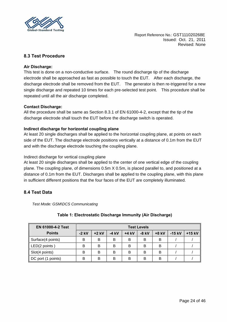
8.3 Test Procedure Air Discharge: This test is done on a non-conductive surface. The round discharge tip of the discharge electrode shall be approached as fast as possible to touch the EUT. After each discharge, the discharge electrode shall be removed from the EUT. The generator is then re-triggered for a new single discharge and repeated 10 times for each pre-selected test point. This procedure shall be repeated until all the air discharge completed. Contact Discharge: All the procedure shall be same as Section 8.3.1 of EN 61000-4-2, except that the tip of the discharge electrode shall touch the EUT before the discharge switch is operated.
Indirect discharge for horizontal coupling plane At least 20 single discharges shall be applied to the horizontal coupling plane, at points on each side of the EUT. The discharge electrode positions vertically at a distance of 0.1m from the EUT and with the discharge electrode touching the coupling plane.
Indirect discharge for vertical coupling plane At least 20 single discharges shall be applied to the center of one vertical edge of the coupling plane. The coupling plane, of dimensions 0.5m X 0.5m, is placed parallel to, and positioned at a distance of 0.1m from the EUT. Discharges shall be applied to the coupling plane, with this plane in sufficient different positions that the four faces of the EUT are completely illuminated. 8.4 Test Data
Test Mode: GSM\DCS Communicating
Table 1: Electrostatic Discharge Immunity (Air Discharge)
Test Levels EN 61000-4-2 Test Points -2 kV +2 kV -4 kV +4 kV -8 kV +8 kV -15 kV +15 kV
Surface(4 points) B B B B B B / / LED(2 points ) B B B B B B / / Slot(4 points) B B B B B B / / DC port (1 points) B B B B B B / /

Report Reference No.: GST111020268E
Issued: Oct. 21, 2011 Revised: None
Page 25 of 46
Table 2: Electrostatic Discharge Immunity (Direct Contact) Test Levels EN 61000-4-2 Test
Points -2 kV +2 kV -4 kV +4 kV -6 kV +6 kV -8 kV +8 kVN/A / / / / / / / /
Table 3: Electrostatic Discharge Immunity (Indirect Contact HCP/ VCP)
Test Levels EN 61000-4-2 Test
Points -2 kV +2 kV -4 kV +4 kV -6 kV +6 kV -8 kV +8 kVFront Side A A A A / / / / Back Side A A A A / / / / Left Side A A A A / / / / Right Side A A A A / / / /
9. ELECTRICAL FAST TRANSIENT IMMUNITY
9.1 Test System Setup 9.2 Test Standard
ETSI EN 301 489-1 V1.8.1/EN 61000-4-4:2004 Test level 2 at 1 kV
EUT
Ground Plane

Report Reference No.: GST111020268E
Issued: Oct. 21, 2011 Revised: None
Page 26 of 46
Test Level
Open Circuit Output Test Voltage ±10%
Level On Power Supply LinesOn I/O (Input/Output)
Signal data and control lines 1 0.5 kV 0.25 kV 2 1 kV 0.5 kV 3 2 kV 1 kV 4 4 kV 2 kV X Special Special
Performance Criterion: B 9.3 Test Procedure The EUT was arranged for Power Line Coupling and for I/O Line Coupling through a capacitive clamp, where applicable. (Note: The I/O coupling test using a capacitive clamp is performed on the I/O interface cables that are longer in length than 3 meters.) A metal ground plane 2.4 meter by 2.0 meter was placed between the floor and the table and is connected to the earth by a 2.0 meter ground rod. The ground rod is connected to the test facility’s electrical earth. 9.4 Test Data
Test Mode: GSM\DCS Communicating
Test Levels (kV) EN 61000-4-4 Test Points +0. 5 -0. 5 +1.0 -1.0 +2.0 -2.0 +4.0 -4.0
L1 A A A A / / / /
L2 A A A A / / / /
Earth / / / / / / / /
L1+L2 A A A A / / / /
L1 + Earth / / / / / / / /
L2 + Earth / / / / / / / /
Power Supply
AC Line of
EUT
L1+L2+Earth / / / / / / / /

Report Reference No.: GST111020268E
Issued: Oct. 21, 2011 Revised: None
Page 27 of 46
10. RF COMMON MODE
10.1 Test Setup 0.1m 10.2Test Standard
ETSI EN 301 489-1 V1.8.1/EN 61000-4-6:2007 Test level 2 at 3 V (r.m.s.), 0.15 MHz ~ 80 MHz,
Test Level
Level Voltage Level (e.m.f.)
(V) 1 1
2 3
3 10
X Special
Performance Criterion: A 10.3 Test Procedure
1) Let the EUT work in test mode and test it. 2) The EUT are placed on an insulating support 0.1 m high above a ground reference plane.
CDN (coupling and decoupling device) is placed on the ground plane about 0.3 m from EUT. Cables between CDN and EUT are as short as possible, and their height above the ground reference plane shall be between 30 and 50 mm (where possible).
3) The disturbance signal described below is injected to EUT through CDN. 4) The EUT operates within its operational mode(s) under intended climatic conditions after
power on. 5) The frequency range is swept from 150 kHz to 80 MHz using 3V signal level, and with the
Wooden TableSG
CDN EUT

Report Reference No.: GST111020268E
Issued: Oct. 21, 2011 Revised: None
Page 28 of 46
disturbance signal 80% amplitude modulated with a 1 kHz sine wave. 6) The rate of sweep shall not exceed 1.5*10-3decades/s. Where the frequency is swept
incrementally, the step size shall not exceed 1% of the start and thereafter 1% of the preceding frequency value.
7) Recording the EUT operating situation during compliance testing and decide the EUT immunity criterion.
10.4 Test Data
Test Mode: GSM\DCS Communicating
Frequency range: 150 kHz to 80 MHz Modulation: Amplitude 80%, 1 kHz sinewave Test level: 3V r.m.s.
Level Voltage Level (e.m.f.)
U0 Pass Fail
1 1 / / 2 3 A / 3 10 / / X Special / /

Report Reference No.: GST111020268E
Issued: Oct. 21, 2011 Revised: None
Page 29 of 46
11. SURGES, LINE TO LINE AND LINE TO GROUND
11.1 Test System Setup 11.2 Test Standard
ETSI EN 301 489-1 V1.8.1 / EN 61000-4-5:2006 L-N: Test level 2 at 1 kV
Test Level
Level Open Circuit Output Test Voltage ±10%
1 0.5 kV 2 1 kV 3 2 kV 4 4 kV X Special
Performance Criterion: B
EUT
Ground Plane

Report Reference No.: GST111020268E
Issued: Oct. 21, 2011 Revised: None
Page 30 of 46
11.3 Test Procedure
1) For line to line coupling mode, provide a 0.5 kV 1.2/50us voltage surge (at open-circuit
condition). 2) At least 5 positive and 5 negative (polarity) tests with a maximum 1/min repetition rate
are conducted during test. 3) Different phase angles are done individually. 4) Record the EUT operating situation during compliance test and decide the EUT
immunity criterion for above each test. 11.4 Test Data
Test Mode: GSM\DCS Communicating Table 1: AC mains power input port
Level Voltage Poll Path Pass Fail
1 0.5 kV ± L-N A /
2 1 kV ± L-N A /
3 2 kV ± L-N, L-PE, N-PE / /
4 4 kV ± L-N, L-PE, N-PE / /

Report Reference No.: GST111020268E
Issued: Oct. 21, 2011 Revised: None
Page 31 of 46
12. VOLTAGE DIPS/ INTERRUPTIONS IMMUNITY TEST
12.1 Test Setup 12.2 Test Standard
ETSI EN 301 489-1 V1.8.1/EN 61000-4-11:2004 Test levels and Performance Criterion
Test Level
Test Level Voltage dip and short
interruptions %UT
Duration (periods)
Performance Criterion
1 0% 0.5 B
2 0% 1 B
3 70% 25 C
4 0% 250 C
12.3 Test Procedure
1) The interruption is introduced at selected phase angles with specified duration. 2) Record any degradation of performance.
EUT
Ground Plane

Report Reference No.: GST111020268E
Issued: Oct. 21, 2011 Revised: None
Page 32 of 46
12.4 Test Data Test Mode: GSM\DCS Communicating
Level U2
(% Reduction) Td (periods) Phase Angle N Pass Fail
1 0% 0.5 0/90/180/270 3 A /
2 0% 1 0/90/180/270 3 A /
3 70% 25 0/90/180/270 3 A /
4 0% 250 0/90/180/270 3 C /
Performance Criterion: A , C

Report Reference No.: GST111020268E
Issued: Oct. 21, 2011 Revised: None
Page 33 of 46
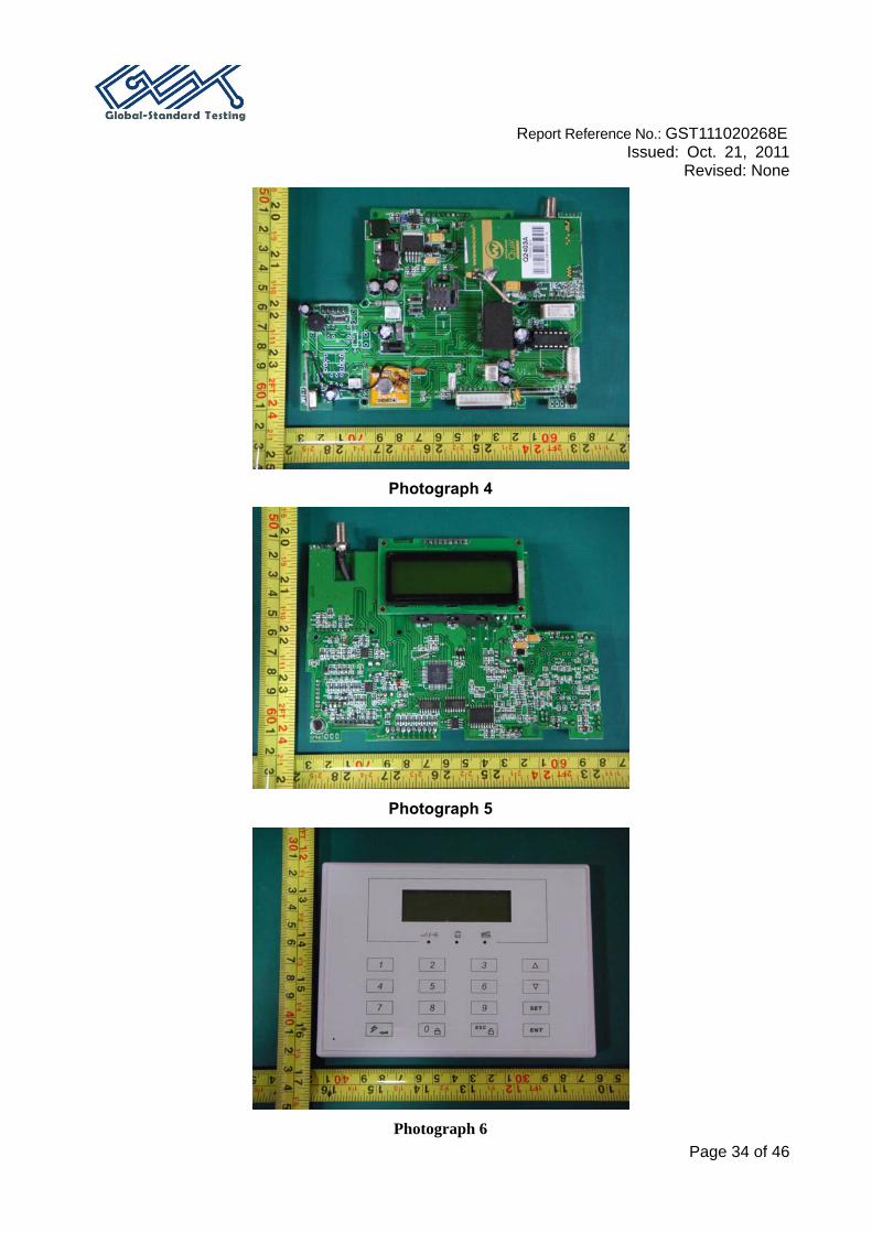
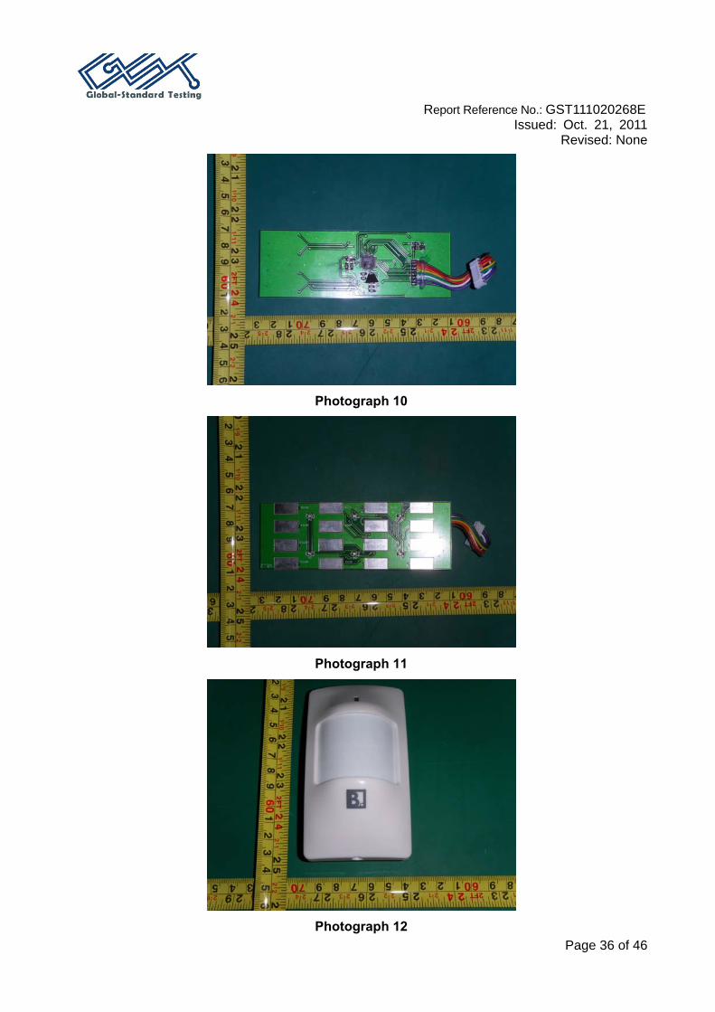
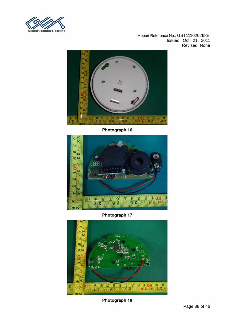
EXHIBIT A - EUT PHOTOGRAPHS
Photograph 1
Photograph 2
Photograph 3
Report Reference No.: GST111020268E
Issued: Oct. 21, 2011 Revised: None
Page 34 of 46
Photograph 4
Photograph 5
Photograph 6

Report Reference No.: GST111020268E
Issued: Oct. 21, 2011 Revised: None
Page 35 of 46
Photograph 7
Photograph 8
Photograph 9
Report Reference No.: GST111020268E
Issued: Oct. 21, 2011 Revised: None
Page 36 of 46
Photograph 10
Photograph 11
Photograph 12

Report Reference No.: GST111020268E
Issued: Oct. 21, 2011 Revised: None
Page 37 of 46
Photograph 13
Photograph 14
Photograph 15
Report Reference No.: GST111020268E
Issued: Oct. 21, 2011 Revised: None
Page 38 of 46
Photograph 16
Photograph 17
Photograph 18

Report Reference No.: GST111020268E
Issued: Oct. 21, 2011 Revised: None
Page 39 of 46
Photograph 19
Photograph 20
Photograph 21
Photograph 22

Report Reference No.: GST111020268E
Issued: Oct. 21, 2011 Revised: None
Page 40 of 46
Photograph 23
Photograph 24
Photograph 25

Report Reference No.: GST111020268E
Issued: Oct. 21, 2011 Revised: None
Page 41 of 46
Photograph 26
Photograph 27
Photograph 28

Report Reference No.: GST111020268E
Issued: Oct. 21, 2011 Revised: None
Page 42 of 46
Photograph 29
Photograph 30
Photograph 31

Report Reference No.: GST111020268E
Issued: Oct. 21, 2011 Revised: None
Page 43 of 46
Photograph 32

Report Reference No.: GST111020268E
Issued: Oct. 21, 2011 Revised: None
Page 44 of 46
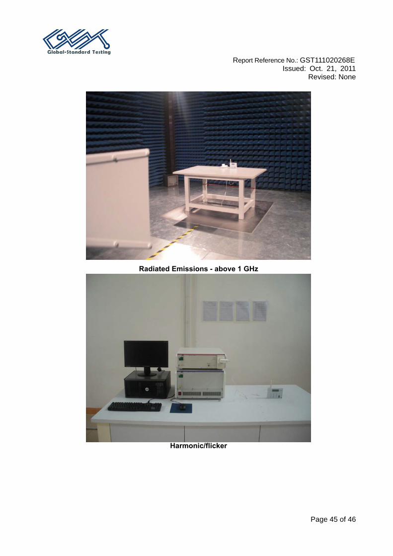
EXHIBIT B – TEST SETUP PHOTOGRAPHS
Conducted Emissions
Radiated Emissions - below 1 GHz
Report Reference No.: GST111020268E
Issued: Oct. 21, 2011 Revised: None
Page 45 of 46
Radiated Emissions - above 1 GHz
Harmonic/flicker

Report Reference No.: GST111020268E
Issued: Oct. 21, 2011 Revised: None
Page 46 of 46
ESD
EFT/Surge/V-dips
END.