gsx2 operator's manual - sokkia · loading an oaf ... bold menu, or drop‐down menu selection...
TRANSCRIPT
ual
s, Inc.
Systems, Inc. All rights reserved.
GSX2Operator’s Man
Part Number 1000759‐01
Rev A
ECO#000324
©Copyright Topcon Positioning System
November, 2012
All contents in this manual are copyrighted by Topcon Positioning

• •
i
Terms and . . . . . . . . . . . . . . . . . . i
Use. . . . . . . . . . . . . . . . . . . . i
Copyri . . . . . . . . . . . . . . . . . . ii
Tradem . . . . . . . . . . . . . . . . . . ii
Disclai . . . . . . . . . . . . . . . . . . ii
Licens . . . . . . . . . . . . . . . . . . iii
Confid . . . . . . . . . . . . . . . . . . iii
Websi . . . . . . . . . . . . . . . . . . iv
Safety . . . . . . . . . . . . . . . . . . iv
Miscel . . . . . . . . . . . . . . . . . . iv
Manua . . . . . . . . . . . . . . . . . . v
GSX2 Feat . . . . . . . . . . . . . . . . . . 2
Unpacking . . . . . . . . . . . . . . . . . . 3
• • • • Table of Contents
P/N: 1000759‐01
Conditions. . . . . . . . . . . . . . . . . . . . . . . . . . . . . . . . . . . . . . . . . .
. . . . . . . . . . . . . . . . . . . . . . . . . . . . . . . . . . . . . . . . . . . . . . . . . . . .
ghts . . . . . . . . . . . . . . . . . . . . . . . . . . . . . . . . . . . . . . . . . . . . . . . .
arks . . . . . . . . . . . . . . . . . . . . . . . . . . . . . . . . . . . . . . . . . . . . . . .
mer of Warranty . . . . . . . . . . . . . . . . . . . . . . . . . . . . . . . . . . . . .
e Agreement. . . . . . . . . . . . . . . . . . . . . . . . . . . . . . . . . . . . . . . . .
entiality . . . . . . . . . . . . . . . . . . . . . . . . . . . . . . . . . . . . . . . . . . . .
te; Other Statements. . . . . . . . . . . . . . . . . . . . . . . . . . . . . . . . . .
. . . . . . . . . . . . . . . . . . . . . . . . . . . . . . . . . . . . . . . . . . . . . . . . . . .
laneous. . . . . . . . . . . . . . . . . . . . . . . . . . . . . . . . . . . . . . . . . . . . .
l Conventions . . . . . . . . . . . . . . . . . . . . . . . . . . . . . . . . . . . . . . .
ures . . . . . . . . . . . . . . . . . . . . . . . . . . . . . . . . . . . . . . . . . . . . . . . .
Your Receiver Kit . . . . . . . . . . . . . . . . . . . . . . . . . . . . . . . . . . . .

ii
. . . . . . . . . . . . . . . . . . 4
. . . . . . . . . . . . . . . . . . 5
. . . . . . . . . . . . . . . . . . 5
. . . . . . . . . . . . . . . . . . 6
. . . . . . . . . . . . . . . . . . 7
. . . . . . . . . . . . . . . . . . 8
. . . . . . . . . . . . . . . . . . 8
. . . . . . . . . . . . . . . . . . 9
. . . . . . . . . . . . . . . . . . 11
. . . . . . . . . . . . . . . . . . 13
. . . . . . . . . . . . . . . . . . 13
. . . . . . . . . . . . . . . . . . 13
. . . . . . . . . . . . . . . . . . 15
. . . . . . . . . . . . . . . . . . 16
. . . . . . . . . . . . . . . . . . 16
. . . . . . . . . . . . . . . . . . 17
. . . . . . . . . . . . . . . . . . 18
P/N: 1000759‐01
System Components . . . . . . . . . . . . . . . . . . . . . . . . . . . . . . . . . . . . . . .
Accessories . . . . . . . . . . . . . . . . . . . . . . . . . . . . . . . . . . . . . . . . . . . . . . .
Technical Documents . . . . . . . . . . . . . . . . . . . . . . . . . . . . . . . . . . . . . . . . . .
Using Sokkia Software With Your Receiver. . . . . . . . . . . . . . . . . . . . . . . . .
Getting Technical Support . . . . . . . . . . . . . . . . . . . . . . . . . . . . . . . . . . . . . .
Website . . . . . . . . . . . . . . . . . . . . . . . . . . . . . . . . . . . . . . . . . . . . . . . . . .
Phone . . . . . . . . . . . . . . . . . . . . . . . . . . . . . . . . . . . . . . . . . . . . . . . . . . .
Receiver Overview . . . . . . . . . . . . . . . . . . . . . . . . . . . . . . . . . . . . . . . . . . . .
Cables. . . . . . . . . . . . . . . . . . . . . . . . . . . . . . . . . . . . . . . . . . . . . . . . . . . . . . .
Memory . . . . . . . . . . . . . . . . . . . . . . . . . . . . . . . . . . . . . . . . . . . . . . . . . . . . .
Internal Batteries . . . . . . . . . . . . . . . . . . . . . . . . . . . . . . . . . . . . . . . . . . . . .
Long‐Range Bluetooth Communication . . . . . . . . . . . . . . . . . . . . . . . . . . .
Power Button . . . . . . . . . . . . . . . . . . . . . . . . . . . . . . . . . . . . . . . . . . . . . . . .
Receiver Status LEDs. . . . . . . . . . . . . . . . . . . . . . . . . . . . . . . . . . . . . . . . . . .
Tracking Status LED . . . . . . . . . . . . . . . . . . . . . . . . . . . . . . . . . . . . . . . .
Recording LED. . . . . . . . . . . . . . . . . . . . . . . . . . . . . . . . . . . . . . . . . . . . .
Bluetooth LED. . . . . . . . . . . . . . . . . . . . . . . . . . . . . . . . . . . . . . . . . . . . .
iii
. . . . . . . . . . . . . . . . . . 19
. . . . . . . . . . . . . . . . . . 20
. . . . . . . . . . . . . . . . . . 20
. . . . . . . . . . . . . . . . . . 21
. . . . . . . . . . . . . . . . . . 22
. . . . . . . . . . . . . . . . . . 23
. . . . . . . . . . . . . . . . . . 25
. . . . . . . . . . . . . . . . . . 27
. . . . . . . . . . . . . . . . . . 30
. . . . . . . . . . . . . . . . . . 31
. . . . . . . . . . . . . . . . . . 32
. . . . . . . . . . . . . . . . . . 35
. . . . . . . . . . . . . . . . . . 38
. . . . . . . . . . . . . . . . . . 39
. . . . . . . . . . . . . . . . . . 40
. . . . . . . . . . . . . . . . . . 42
. . . . . . . . . . . . . . . . . . 42
P/N: 1000759‐01
Battery LED . . . . . . . . . . . . . . . . . . . . . . . . . . . . . . . . . . . . . . . . . . . . . . .
Turning On/Off the Receiver . . . . . . . . . . . . . . . . . . . . . . . . . . . . . . . . . . . .
Using Internal and External Power Sources . . . . . . . . . . . . . . . . . . . . . . . .
Internal Batteries . . . . . . . . . . . . . . . . . . . . . . . . . . . . . . . . . . . . . . . . . .
Charging the Batteries . . . . . . . . . . . . . . . . . . . . . . . . . . . . . . . . . . . . . .
Insufficient Power . . . . . . . . . . . . . . . . . . . . . . . . . . . . . . . . . . . . . . . . . . . . .
Viewing Receiver Information . . . . . . . . . . . . . . . . . . . . . . . . . . . . . . . . . . .
Loading New Firmware. . . . . . . . . . . . . . . . . . . . . . . . . . . . . . . . . . . . . . . . .
About the OAF. . . . . . . . . . . . . . . . . . . . . . . . . . . . . . . . . . . . . . . . . . . . . . . .
Checking the Receiver’s OAF. . . . . . . . . . . . . . . . . . . . . . . . . . . . . . . . .
Loading an OAF. . . . . . . . . . . . . . . . . . . . . . . . . . . . . . . . . . . . . . . . . . . .
Clearing the NVRAM . . . . . . . . . . . . . . . . . . . . . . . . . . . . . . . . . . . . . . . . . . .
Setting Up the Base Receiver . . . . . . . . . . . . . . . . . . . . . . . . . . . . . . . . . . . .
Setting Up the Rover Receiver . . . . . . . . . . . . . . . . . . . . . . . . . . . . . . . . . . .
Measuring Antenna Height . . . . . . . . . . . . . . . . . . . . . . . . . . . . . . . . . . . . .
Setting Recording Parameters . . . . . . . . . . . . . . . . . . . . . . . . . . . . . . . . . . .
Logging Rates. . . . . . . . . . . . . . . . . . . . . . . . . . . . . . . . . . . . . . . . . . . . . . . . .
iv
. . . . . . . . . . . . . . . . . . 42
. . . . . . . . . . . . . . . . . . 43
. . . . . . . . . . . . . . . . . . 44
. . . . . . . . . . . . . . . . . . 45
. . . . . . . . . . . . . . . . . . 46
. . . . . . . . . . . . . . . . . . 47
. . . . . . . . . . . . . . . . . . 50
. . . . . . . . . . . . . . . . . . 51
. . . . . . . . . . . . . . . . . . 53
. . . . . . . . . . . . . . . . . . 54
. . . . . . . . . . . . . . . . . . 54
. . . . . . . . . . . . . . . . . . 55
. . . . . . . . . . . . . . . . . . 62
. . . . . . . . . . . . . . . . . . 63
. . . . . . . . . . . . . . . . . . 63
. . . . . . . . . . . . . . . . . . 64
. . . . . . . . . . . . . . . . . . 65
P/N: 1000759‐01
Recording Data . . . . . . . . . . . . . . . . . . . . . . . . . . . . . . . . . . . . . . . . . . . . . . .
Managing Files. . . . . . . . . . . . . . . . . . . . . . . . . . . . . . . . . . . . . . . . . . . . . . . .
Downloading and Deleting Files . . . . . . . . . . . . . . . . . . . . . . . . . . . . . .
Check This First! . . . . . . . . . . . . . . . . . . . . . . . . . . . . . . . . . . . . . . . . . . . . . .
Powering Problems. . . . . . . . . . . . . . . . . . . . . . . . . . . . . . . . . . . . . . . . . . . .
Receiver Problems . . . . . . . . . . . . . . . . . . . . . . . . . . . . . . . . . . . . . . . . . . . .
Long‐Range Bluetooth Problems . . . . . . . . . . . . . . . . . . . . . . . . . . . . . . . . .
Bluetooth Problems . . . . . . . . . . . . . . . . . . . . . . . . . . . . . . . . . . . . . . . . . . .
SRU Problems . . . . . . . . . . . . . . . . . . . . . . . . . . . . . . . . . . . . . . . . . . . . . . . .
Cleaning and Storing the Receiver. . . . . . . . . . . . . . . . . . . . . . . . . . . . . . . .
Getting Customer Support . . . . . . . . . . . . . . . . . . . . . . . . . . . . . . . . . . . . . .
General Details . . . . . . . . . . . . . . . . . . . . . . . . . . . . . . . . . . . . . . . . . . . . . . .
General Warnings . . . . . . . . . . . . . . . . . . . . . . . . . . . . . . . . . . . . . . . . . . . .
Receiver Warnings . . . . . . . . . . . . . . . . . . . . . . . . . . . . . . . . . . . . . . . . . . . .
Usage Warnings . . . . . . . . . . . . . . . . . . . . . . . . . . . . . . . . . . . . . . . . . . . . . .
FCC Compliance. . . . . . . . . . . . . . . . . . . . . . . . . . . . . . . . . . . . . . . . . . . . . . .
Industry Canada Compliance . . . . . . . . . . . . . . . . . . . . . . . . . . . . . . . . . . . .

v
. . . . . . . . . . . . . . . . . . 66
ive 1999/5/EC . . . . . . 66
. . . . . . . . . . . . . . . . . . 67
. . . . . . . . . . . . . . . . . . 71
. . . . . . . . . . . . . . . . . . 71
. . . . . . . . . . . . . . . . . . 72
P/N: 1000759‐01
Community of Europe Compliance . . . . . . . . . . . . . . . . . . . . . . . . . . . . . . .
European Community Declaration of Conformity with R&TTE Direct
Declaration of Conformity (R&TTE Directive 1999/5/EC) . . . . . . . . . . . . .
WEEE Directive . . . . . . . . . . . . . . . . . . . . . . . . . . . . . . . . . . . . . . . . . . . . . . .
Bluetooth Transmission Statements/Compliance . . . . . . . . . . . . . . . . . . .
Korean KC‐RF Compliance . . . . . . . . . . . . . . . . . . . . . . . . . . . . . . . . . . . . . .

vi
nual (the “Manual”) have been prepared by Topcon ed to assist owners with the use of the receiver and
ood knowledge of the safe use of the product and ent protection agency for both private use and
Preface P/N: 1000759‐01
• • • • • • Preface
Thank you for purchasing this Sokkia product. The materials available in this MaPositioning Systems, Inc. (“TPS”) for owners of Sokkia products, and are designits use is subject to these terms and conditions (the “Terms and Conditions”).
Terms and Conditions
Use
This product is designed to be used by a professional. The user should have a gimplement the types of safety procedures recommended by the local governmcommercial job sites.
Please read the terms and conditions carefully.

Pre
face
vii
opyrighted material of TPS. All rights are reserved. y, publish, distribute, or allow any third party access xpress written consent and may only use such data in this Manual are a valuable asset of TPS and d are the result of original selection, coordination
s or registered trademarks of Topcon Positioning n. The Bluetooth® word mark and logos are owned ems, Inc. is used under license. Other product and wners.
COMPANYING THE PRODUCT, THIS MANUAL AND TPS DISCLAIMS ANY IMPLIED WARRANTY OF AND ITS DISTRIBUTORS SHALL NOT BE LIABLE FOR FOR INCIDENTAL OR CONSEQUENTIAL DAMAGES RIAL OR THE RECEIVER. SUCH DISCLAIMED RUCTION OF DATA, LOSS OF PROFIT, SAVINGS OR NSIBLE OR LIABLE FOR DAMAGES OR COSTS
Terms and Conditions P/N: 1000759‐01
Copyrights
All information contained in this Manual is the intellectual property of, and cDo not use, access, copy, store, display, create derivative works of, sell, modifto, any graphics, content, information or data in this Manual without TPS’ einformation for the care and operation of the receiver. The information and are developed by the expenditure of considerable work, time and money, anand arrangement by TPS.
Trademarks
GSX2™, SRU™, Magnet™, Pocket‐3D™, Sokkia®, and Topcon® are trademarkSystems (TPS). Windows® is a registered trademark of Microsoft Corporatioby Bluetooth SIG, Inc. and any use of such marks by Topcon Positioning Systcompany names mentioned herein may be trademarks of their respective o
Disclaimer of Warranty
EXCEPT FOR ANY WARRANTIES IN AN APPENDIX OR A WARRANTY CARD ACTHE RECEIVER ARE PROVIDED “AS‐IS.” THERE ARE NO OTHER WARRANTIES. MERCHANTABILITY OR FITNESS FOR ANY PARTICULAR USE OR PURPOSE. TPSTECHNICAL OR EDITORIAL ERRORS OR OMISSIONS CONTAINED HEREIN; NORRESULTING FROM THE FURNISHING, PERFORMANCE OR USE OF THIS MATEDAMAGES INCLUDE BUT ARE NOT LIMITED TO LOSS OF TIME, LOSS OR DESTREVENUE, OR LOSS OF THE PRODUCT’S USE. IN ADDITION TPS IS NOT RESPO

Pre
face
viii
FTWARE, CLAIMS BY OTHERS, INCONVENIENCE, OR AGES OR OTHERWISE TO YOU OR ANY OTHER
from a TPS website (the “Software”) in connection his Manual and an agreement to abide by these ansferable license to use such Software under the puter. You may not assign or transfer the Software ective until terminated. You may terminate the ate the license if you fail to comply with any of the rmination of the use of the receiver. All ownership, g to TPS. If these license terms are not acceptable,
formation”) are the confidential and proprietary degree of care no less stringent that the degree of othing in this paragraph shall restrict you from or appropriate to operate or care for the receiver. l. In the event you become legally compelled to tice so that it may seek a protective order or other
Terms and Conditions P/N: 1000759‐01
INCURRED IN CONNECTION WITH OBTAINING SUBSTITUTE PRODUCTS OR SOANY OTHER COSTS. IN ANY EVENT, TPS SHALL HAVE NO LIABILITY FOR DAMPERSON OR ENTITY IN EXCESS OF THE PURCHASE PRICE FOR THE RECEIVER.
License Agreement
Use of any computer programs or software supplied by TPS or downloaded with the receiver constitutes acceptance of these Terms and Conditions in tTerms and Conditions. The user is granted a personal, non‐exclusive, non‐trterms stated herein and in any case only with a single receiver or single comor this license without the express written consent of TPS. This license is efflicense at any time by destroying the Software and Manual. TPS may terminTerms or Conditions. You agree to destroy the Software and manual upon tecopyright and other intellectual property rights in and to the Software belonreturn any unused software and manual.
Confidentiality
This Manual, its contents and the Software (collectively, the “Confidential Ininformation of TPS. You agree to treat TPS’ Confidential Information with a care you would use in safeguarding your own most valuable trade secrets. Ndisclosing Confidential Information to your employees as may be necessarySuch employees must also keep the Confidentiality Information confidentiadisclose any of the Confidential Information, you shall give TPS immediate noappropriate remedy.

Pre
face
ix
other advertisements or TPS literature or made by nditions (including the Software license, warranty
r malfunction of the product. The receiver should view and heed the safety warnings in an Appendix.
canceled, at any time by TPS. The above Terms and of the State of California, without reference to
Terms and Conditions P/N: 1000759‐01
Website; Other Statements
No statement contained at the TPS website (or any other website) or in any an employee or independent contractor of TPS modifies these Terms and Coand limitation of liability).
Safety
Improper use of the receiver can lead to injury to persons or property and/oonly be repaired by authorized TPS warranty service centers. Users should re
Miscellaneous
The above Terms and Conditions may be amended, modified, superseded, orConditions will be governed by, and construed in accordance with, the lawsconflict of laws.
Pre
face
x
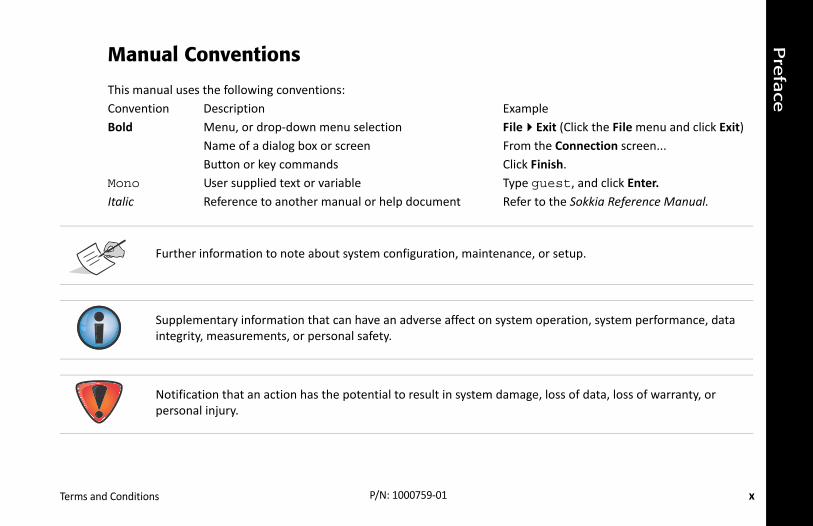
ExampleFileExit (Click the File menu and click Exit)From the Connection screen...Click Finish.Type guest, and click Enter.Refer to the Sokkia Reference Manual.
enance, or setup.
system operation, system performance, data
damage, loss of data, loss of warranty, or
Terms and Conditions P/N: 1000759‐01
Manual Conventions
This manual uses the following conventions:Convention DescriptionBold Menu, or drop‐down menu selection
Name of a dialog box or screenButton or key commands
Mono User supplied text or variableItalic Reference to another manual or help document
Further information to note about system configuration, maint
Supplementary information that can have an adverse affect onintegrity, measurements, or personal safety.
Notification that an action has the potential to result in systempersonal injury.

1
SS receiver for static and cable‐free stop‐and‐eiver board, based on industry‐leading technology, ge Bluetooth communication technology. The GSX2 y tracking signals from multi‐constellation satellite
job site system suitable for short range (up to 300m as a Network RTK Rover by adding network option
ddition to superior vibration and shock resistance. emium GNSS performance within new systems and ions.
Introduction P/N: 1000759‐01
• • • • • • Introduction
Sokkia’s GSX2 receiver is a compact, lightweight, and completely integrated GNgo/kinematic applications. The integrated receiver design includes a GNSS recinternal long‐life batteries, memory storage, and Sokkia’s innovative Long‐Randelivers world‐class positioning and navigation capability to your application bsystems, including GPS, GLONASS, and SBAS.
Sokkia’s exclusive Long‐Range Bluetooth technology provides the perfect smallfrom the Base station) RTK communication. You can also use the GSX2 receiverauthorization to the receiver and cellular‐enabled controller.
The GSX2 offers complete IP67 protection against dust and water ingress, in aThe Sokkia communication interface allows you to quickly integrate Sokkia’s prquickly deliver world‐class positioning and navigation support to your applicat

Intro
ductio
n
2
r
operation, allowing for a simplified setup and less
GSX2 Features P/N: 1000759‐01
Figure 1: GSX2 Receive
GSX2 Features
The GSX2 receiver’s advanced design eliminates the need for cables during parts to keep track of. The GSX2 receiver features the following:
• Compact, lightweight, and rugged design• Industry‐leading antenna technology • A premier multi‐constellation GNSS board

Intro
ductio
n
3
s.
nfiguration
requirements. Typically, the GSX2 supports the
cessories (depending on your purchase) that ived the items listed in this section. Make sure the or damaged, contact your Sokkia dealer or Sokkia
Unpacking Your Receiver Kit P/N: 1000759‐01
• Multi‐channel Long‐Range Bluetooth technology for RTK correction• 2 GB internal memory• Internal batteries, providing at least 15 hours of operation in any co• A highly visible display panel with single‐button operation• USB and power/RS‐232 ports
The GSX2 can be configured in a variety of ways, depending on your projectfollowing operation modes:
• Static post‐processing• Long‐Range Bluetooth and Rover RTK• Network Rover RTK• SBAS‐enabled navigation
Unpacking Your Receiver Kit
This section describes the documentation, standard kit components, and acaccompany your receiver. When you unpack your receiver kit, verify you receitems do not appear damaged from shipment. If any of the items are missingtechnical support. See “Obtaining Customer Support” on page 7.
• Standard components are illustrated in Figure 2.• Receiver accessories are illustrated in Figure 3.• Receiver documentation is listed on page 5.

Intro
ductio
n
4
ponents
u need to install to use the USB port for
Unpacking Your Receiver Kit P/N: 1000759‐01
System Components
The items illustrated in Figure 2 are included with your receiver.
Figure 2: Standard System Com
The Sokkia Receiver Utilities CD includes USB drivers, which yocommunications.

Intro
ductio
n
5
o improve system flexibility and job site efficiency. r Sokkia dealer.
ries
p and use your new receiver quickly and efficiently.
ns detailed information on how to use your new
cument that contains detailed information on how D. For more information about the SRU software,
Technical Documents P/N: 1000759‐01
Accessories
Sokkia offers a wide variety of accessories (see Figure 3) specially designed tFor more details on the optional accessories available for GSX2, contact you
Figure 3: Receiver Accesso
Technical Documents
The GSX2 Manual CD includes two manuals (listed below) that help you set u
• GSX2 Operator’s Manual – An on‐screen help document that contaireceiver.
• Sokkia Receiver Utility (SRU) Reference Guide – An on‐screen help doto use the SRU software included on the Sokkia Receiver Utilities Csee “Using Sokkia Software With Your Receiver”.
Intro
ductio
n
6
and MAGNET Field™ or Pocket‐3D applications for the receiver and other external devices, manage
ceivers and peripheral devices. You can install it on kkia Receiver Utilities CD that accompanied your
mmunication, cloud storage, data collection and more. Contact your Sokkia dealer for more .
mobile platforms. Pocket‐3D simplifies data r part of the job site quickly and efficiently. Contact
Using Sokkia Software With Your Receiver P/N: 1000759‐01
Using Sokkia Software With Your Receiver
Use the GSX2 receiver in conjunction with the Sokkia Receiver Utility (SRU) a cable‐free positioning solution. Sokkia software enables you to configure files, collect data, and perform survey and construction work flows.
The Sokkia Receiver Utility (SRU) is a hardware configuration software for redesktop computers and data controllers. This program is provided on the Soreceiver. A SRU help document is provided on the GSX2 CD.
Sokkia’s MAGNET Field™ software for data controllers provides real‐time coexchange, and field solutions, such as topo, staking, roads, calculations, andinformation about MAGNET Field and the entire MAGNET Enterprise system
Pocket‐3D is a program that runs on data controllers with Windows CE® andcollection, allowing you to check cuts and fills, layout points and survey all oyour Sokkia dealer for more information about Pocket‐3D.

Intro
ductio
n
7
th the receiver, see “Troubleshooting” on page 45
aSupport.com) for technical support.
mation for better and faster service:
curredessages that precede or follow the problem
ation, click Information in SRU, select Save to
office exhibiting the problem. These perating system information, memory and
er and steps to reproduce the problem.ns when the problem occurred.
of the problem.
Getting Technical Support P/N: 1000759‐01
Getting Technical Support
Before contacting a Sokkia customer representative about any problems wifor some solutions that may fix the issue.
Contact your local Sokkia dealer or visit the Sokkia Support Site (www.Sokki
When contacting Sokkia for technical assistance, provide the following infor
1. A description of the following:– Field operation that was being performed when the problem oc– Details of the unexpected behavior, symptoms, and any error m– Problem occurrence frequency or patterns
2. Receiver information and configuration settings. For receiver informFile, enter a file name, and save it to the computer.
3. Specifications of mobile devices and computers used in the field orspecifications should include model information, version number, ostorage capacity, etc.
4. Information about the system software, including the version numb5. A description of the field environment and/or observation conditio
For quick and effective support, provide a detailed description

Intro
ductio
n
8
cts. The support site provides access to Sokkia field
Getting Technical Support P/N: 1000759‐01
Website
The Sokkia website provides current information about Sokkia’s line of produand office software, manuals, frequently asked questions, and so forth.
To access the Sokkia website, visit www.sokkia.com.
To access the Sokkia support site, visit www.sokkiasupport.com.
Phone
To contact Sokkia Customer Support by phone, call:
• 1-800-4-Sokkia or 1-800-476-5542
• 1-866-4-Topcon or 1-866-486-7266
9
r board, antenna, batteries, memory storage, and
osed by the radome, which is securely surrounded
formation are located on the bottom of the
on. The display panel enables you to view the ions” on page 14.
' thread pole or adapter.
ceiver labels. The product identification label matrix code. You can scan the QR code with any QR age at the Sokkia website (www.sokkia.com).
Getting Acquainted P/N: 1000759‐01
• • • • • • Getting Acquainted
The GSX2 receiver enclosure is fully sealed and incorporates the GNSS receivewireless communication device.
Receiver Overview
The upper portion of the receiver contains GNSS and Bluetooth antennas enclby a shock‐absorbing rubber bumper.
An easy‐to‐operate display panel, mounting socket, and labels with receiver inreceiver’s magnesium alloy lower enclosure.
The GSX2 receiver has a highly‐visible display panel with single‐button operatireceiver’s operational status. For more information, see “Display Panel Operat
The mounting socket (Figure 4) connects the receiver to either a standard 5/8'
You can locate regulatory and product identification information on the two recontains the serial number and part number along with a quick response (QR) code application on a smart phone and it will open the product information p

Gettin
g A
cquain
ted
10
view
QR Code
RubberBumper
Receiver Overview P/N: 1000759‐01
.
Figure 4: Bottom Enclosure Over
LED Display Panel
Ports Panel
Product ID Label withPart Number and
Serial Number
MountingSocket
Gettin
g A
cquain
ted
11
adapter. Table 1 describes the cables included with
he receiver port. Turn the cable lock clockwise le, turn the lock counter‐clockwise, and then
able Illustration
Cables P/N: 1000759‐01
Cables
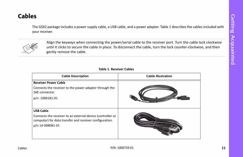
The GSX2 package includes a power supply cable, a USB cable, and a power your receiver.
Align the keyways when connecting the power/serial cable to tuntil it clicks to secure the cable in place. To disconnect the cabgently remove the cable.
Table 1. Receiver Cables
Cable Description C
Receiver Power CableConnects the receiver to the power adapter through the SAE connector.
p/n: 1000181‐01
USB CableConnects the receiver to an external device (controller or computer) for data transfer and receiver configuration.p/n 14‐008081‐01

Gettin
g A
cquain
ted
12
able Illustration
Cables P/N: 1000759‐01
Power AdapterCharges the receiver when connected to a grounded outlet and the power charger cable.p/n 22‐034101‐01
Power Charger CableConnects the power adapter to a grounded outlet. Sever‐al options are available for the power charger cable based on your country. If the kit does not include a power charger cable, contact your Sokkia dealer. Refer to the these part numbers for available power charger cables:p/n 14‐008052‐01 (USA connector)p/n 14‐008054‐01 (EUR connector)p/n 14‐008074‐01 (AUS connector)p/n 1000475‐01 (BRL connector)
Power and Serial CableConnects the receiver to the power adapter through the SAE connector and an external device through the RS‐232 port (DB9 connector). Typically, this cable is not shipped with the standard kit configuration but is available to purchase separately.p/n: 1000182‐01
Table 1. Receiver Cables
Cable Description C
Gettin
g A
cquain
ted
13
ovides up to 2 GB of data storage. As data is logged . See “Recording LED” on page 17 for more see “Managing Files” on page 43.
ion batteries, so there is no battery door or d power adapter or an external power source. See
ables multiple (up to 3) cable‐free connections to can also connect the receiver to other Class 1‐ and sing Bluetooth wireless technology concurrently
3 differential corrections between two GSX2 onal external radios for corrections. For more
Memory P/N: 1000759‐01
Memory
The GSX2 is equipped with an internal, non‐removable memory card that prto the receiver’s memory, the REC LED displays the memory capacity statusinformation. To access the raw data files in the receiver’s internal memory,
Internal Batteries
The GSX2 receiver was designed with two internal, non‐removable Lithium‐connectors to worry about. The batteries are easily charged using the supplie“Internal Batteries” on page 21 for more information.
Long-Range Bluetooth Communication
The GSX2 receiver has integrated Long‐Range Bluetooth technology that enother GSX2 devices for Long‐Range Bluetooth Base/Rover RTK systems. You Class 2‐enabled Bluetooth devices (such as data collectors and computers) uwith Long‐Range Bluetooth connections.
Sokkia’s Long‐Range Bluetooth technology enables communication of RTCMreceivers over Bluetooth (up to 300 meters), eliminating the need for additiinformation, see “Field System Setup” on page 37.

14
ta recording. The LEDs display the status of the tooth connections, and batteries. This chapter
eryT)
Display Panel Operations P/N: 1000759‐01
• • • • • • Display Panel Operations
The LED display panel (Figure 5) enables you to control receiver power and dasatellite tracking, recording/memory capacity, Bluetooth and Long‐Range Bluedescribes the different LED blink patterns and what they mean.
Figure 5: LED Display Panel
Power (PWR)
Status(STAT)
Recording(REC)
Bluetooth(BT)
Batt(BAT
Disp
lay P
anel O
pera
tions
15
ich the button is pressed and held determines how
s
LED DESCRIPTION
til the startup is complete, and then the LED
e Power button when the Battery LED is solid
e Power button when the Status LED is solid
e Power button when the Recording LED is
sible. If you are unsure about this action, button until all LEDs return to normal.
and the receiver has not taken any action.
description.
Power Button P/N: 1000759‐01
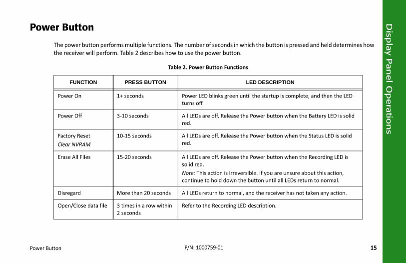
Power Button
The power button performs multiple functions. The number of seconds in whthe receiver will perform. Table 2 describes how to use the power button.
Table 2. Power Button Function
FUNCTION PRESS BUTTON
Power On 1+ seconds Power LED blinks green unturns off.
Power Off 3‐10 seconds All LEDs are off. Release thred.
Factory Reset Clear NVRAM
10‐15 seconds All LEDs are off. Release thred.
Erase All Files 15‐20 seconds All LEDs are off. Release thsolid red.Note: This action is irrevercontinue to hold down the
Disregard More than 20 seconds All LEDs return to normal,
Open/Close data file 3 times in a row within 2 seconds
Refer to the Recording LED

Disp
lay P
anel O
pera
tions
16
cked satellites, memory capacity, and Bluetooth LED.
.s
escription
cked GPS satellite.
cked GLONASS satellite.
there are no tracked tions. It is Off otherwise.
Receiver Status LEDs P/N: 1000759‐01
Receiver Status LEDs
There are four status LEDs to provide information about the battery life, trawireless connectivity. This section describes the color and behavior of each
Tracking Status LED
The tracking status LED displays how many satellites the receiver is trackingTable 3. Status LED Pattern
LED Color D
1 One blink per tra
2 One blink per tra
3 One blink when satellites or solu

Disp
lay P
anel O
pera
tions
17
ow much memory the receiver has available for
rns
Description
icates data is being written
dicates no data is being
een and red LEDs indicate ing deleted.
d and yellow LEDs indicate ard is being initialized or
.
Receiver Status LEDs P/N: 1000759‐01
Recording LED
The memory LED indicates if data is being written to memory and displays hrecording.
Table 4. Recording LED Patte
Display Function
Logging data
Each blink indto memory.
File closed
A solid light inrecorded.
Erasing memoryAlternating grall files are be
Formatting memoryAlternating rethe memory cformatted.
Missing or faulty memory
The LED is off

Disp
lay P
anel O
pera
tions
18
ribes the activity. rns
ription
for a connection.
on is established.
luetooth technology . The LED blinks for each ds.
Receiver Status LEDs P/N: 1000759‐01
Bluetooth LED
The Bluetooth LED displays the status of the Bluetooth activity. Table 5 descTable 5. Bluetooth LED Patte
LED Color Desc
Bluetooth is on and waiting
A single Bluetooth connecti
Multi‐channel Long‐Range Bconnections are establishedconnection every five secon
Bluetooth is turned off.
Disp
lay P
anel O
pera
tions
19
en an external power source is utilized, the LED for more information. s
tion
ERIES IN USE
PWR LED IS SOLID GREEN
nal batteries are fully charged.
pacity; the batteries are being charged.
pacity; the batteries are being charged.
ity; the batteries are being charged.
ource, and the batteries are fully charged.
ource, and the batteries are being charged.
Receiver Status LEDs P/N: 1000759‐01
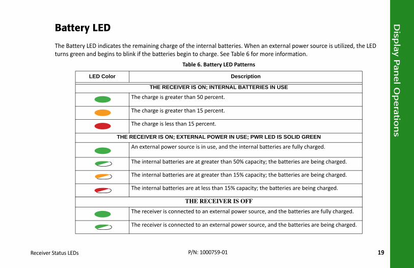
Battery LED
The Battery LED indicates the remaining charge of the internal batteries. Whturns green and begins to blink if the batteries begin to charge. See Table 6
Table 6. Battery LED Pattern
LED Color Descrip
THE RECEIVER IS ON; INTERNAL BATT
The charge is greater than 50 percent.
The charge is greater than 15 percent.
The charge is less than 15 percent.
THE RECEIVER IS ON; EXTERNAL POWER IN USE;
An external power source is in use, and the inter
The internal batteries are at greater than 50% ca
The internal batteries are at greater than 15% ca
The internal batteries are at less than 15% capac
THE RECEIVER IS OFF
The receiver is connected to an external power s
The receiver is connected to an external power s

20
s, and use an external power source.
lash. When the receiver is turned on, the receiver’s ion.
nd less than 10 seconds (release the power button ng turned off by mistake.
connected to the power/serial port. If an external .
s when it is turned off. If the receiver is teries may become fully discharged. You will efore use.
Managing Power P/N: 1000759‐01
• • • • • • Managing Power
This chapter describes how to power the receiver, charge the internal batterie
Turning On/Off the Receiver
To turn on the receiver, press and hold the power button until the LEDs briefly fchannels initialize and begin tracking all visible satellites at any time and locat
To turn off the receiver, press and hold the power button for more than three awhen the BATT LED blinks solid red). This delay prevents the receiver from bei
Using Internal and External Power Sources
The receiver is powered by the internal batteries or an external power sourcepower source is connected, the receiver draws power from it over the battery
The receiver will draw a small amount of power from the batterieplaced in storage for a long period, such as a few months, the batneed to use an external power supply or recharge the batteries b
Managin
g P
ow
er
21
battery, with 6.5 to 30 VDC to operate the receiver. rce requirements to power the receiver and charge
. When there is no valid external power source will draw its power from two high‐capacity s of operation provided by the internal batteries
. For maximum operating time, fully charge the
Using Internal and External Power Sources P/N: 1000759‐01
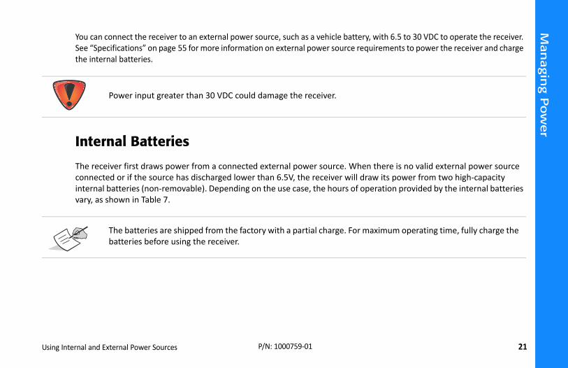
You can connect the receiver to an external power source, such as a vehicle See “Specifications” on page 55 for more information on external power southe internal batteries.
Internal Batteries
The receiver first draws power from a connected external power sourceconnected or if the source has discharged lower than 6.5V, the receiver internal batteries (non‐removable). Depending on the use case, the hourvary, as shown in Table 7.
Power input greater than 30 VDC could damage the receiver.
The batteries are shipped from the factory with a partial chargebatteries before using the receiver.
Managin
g P
ow
er
22
llow and then red, depending on the remaining n external power source, the batteries begin to
Approx.Hours of
Operationa
Rover. 15
om a ata
17
20
Using Internal and External Power Sources P/N: 1000759‐01
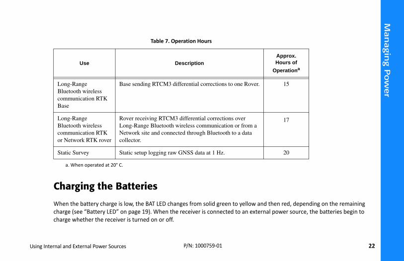
Charging the Batteries
When the battery charge is low, the BAT LED changes from solid green to yecharge (see “Battery LED” on page 19). When the receiver is connected to acharge whether the receiver is turned on or off.
Table 7. Operation Hours
Use Description
a. When operated at 20° C.
Long-Range Bluetooth wireless communication RTK Base
Base sending RTCM3 differential corrections to one
Long-Range Bluetooth wireless communication RTK or Network RTK rover
Rover receiving RTCM3 differential corrections overLong-Range Bluetooth wireless communication or frNetwork site and connected through Bluetooth to a dcollector.
Static Survey Static setup logging raw GNSS data at 1 Hz.
Managin
g P
ow
er
23
ication port.e power adapter.ive hours to fully charge the batteries. (You they are full.)
t connected, the receiver will shut down and the display panel for the battery charge status. See
munication ports become de‐activated.
llowing:
iver’s port. to the receiver port.
ble in place.
harging. The socket should be located near the
Insufficient Power P/N: 1000759‐01
To charge the batteries:
1. Connect the supplied power cable to the receiver’s power/commun2. Connect the power cable SAE connector to the SAE connector of th3. Plug the power adapter into an available outlet for approximately f
cannot over charge the batteries; the batteries stop charging whenThe BAT LED blinks as the batteries charge.
Insufficient Power
If the batteries become fully discharged and an external power supply is noautomatically save recorded files. To avoid disruptions, check the BAT LED on“Battery LED” on page 19 for more information.
If the receiver shuts down due to insufficient power, the receiver and all com
To restore power to your receiver and turn it back on, do one or all of the fo
• Recharge the batteries.• Make sure the power/serial cable is correctly connected to the rece
a. Align the keyways when connecting the power/serial cable
b. Turn the cable lock clockwise until it clicks to secure the ca
Use a grounded wall outlet or grounded surge protector while cequipment and easily accessible.
Managin
g P
ow
er
24
nd then gently remove the cable.
provided by Sokkia on the product. Failure to
Insufficient Power P/N: 1000759‐01
c. To disconnect the cable, turn the lock counter‐clockwise, a• Connect the receiver to a different power source.
Power supplied to the receiver should match the specificationscomply with these specifications may damage the receiver.

25
Option Authorization File (OAF), update firmware, er Utility (SRU) software that was supplied on the r Utility (SRU) Reference Manual.
ceiver information, such as hardware and firmware
and click Connect. window (Figure 6) appears.
Configuring the Receiver P/N: 1000759‐01
• • • • • • Configuring the Receiver
The sections in this chapter describe receiver options, and how to load a new and perform a factory reset. To do this, you will need to use the Sokkia ReceivGSX2 CD. For information about installing the software, see the Sokkia Receive
Viewing Receiver Information
In the Sokkia Receiver Utility (SRU), the Receiver Info window displays basic reversions, RAM size, receiver ID, serial number, etc.
To open the Receiver Info window:
1. Connect the receiver to a computer and open SRU. 2. In SRU, connect to the receiver. 3. Click DeviceApplication ModeReceiver Managing.4. Click DeviceConnect.5. In the Connection Parameters window, select the correct serial port, 6. In the SRU main window, click the Information icon. The Receiver Info

Config
urin
g th
e R
ece
iver
26
o
Viewing Receiver Information P/N: 1000759‐01
Figure 6: SRU – Receiver Inf
Config
urin
g th
e R
ece
iver
27
and decompress. This file contains the following
le receiver accessory (p/n: 100182‐01).
rial Port and the port name, and then click
Loading New Firmware P/N: 1000759‐01
Loading New Firmware
Receiver board firmware is released as a compressed file that you downloadtwo files:
• ramimage.ldr – the Receiver board RAM file• main.ldp – the Receiver board Flash file
To upload firmware files to the receiver:
1. Connect the receiver to a computer using the Power and Serial cab2. To connect to the receiver in SRU:
a. Click DeviceApplication ModeReceiver Managing.
b. Click DeviceConnect.
c. In the Connection Parameters window (Figure 7), select SeConnect.

Config
urin
g th
e R
ece
iver
28
s Window
irmware window (Figure 8) displays. This iver.
re 8).
Loading New Firmware P/N: 1000759‐01
Figure 7: Connection Parameter
3. Click the Firmware icon in the SRU main window. The Upload Fwindow enables you to upload firmware files to the connected rece
4. Make sure Receiver is selected in the Device field.5. (Recommended) Select Soft Break as the Capture Method.6. Browse for and select the receiver board’s RAM and Flash files (Figu
Select USB Port

Config
urin
g th
e R
ece
iver
29
indow
igure 9).
Loading New Firmware P/N: 1000759‐01
Figure 8: Upload Firmware W
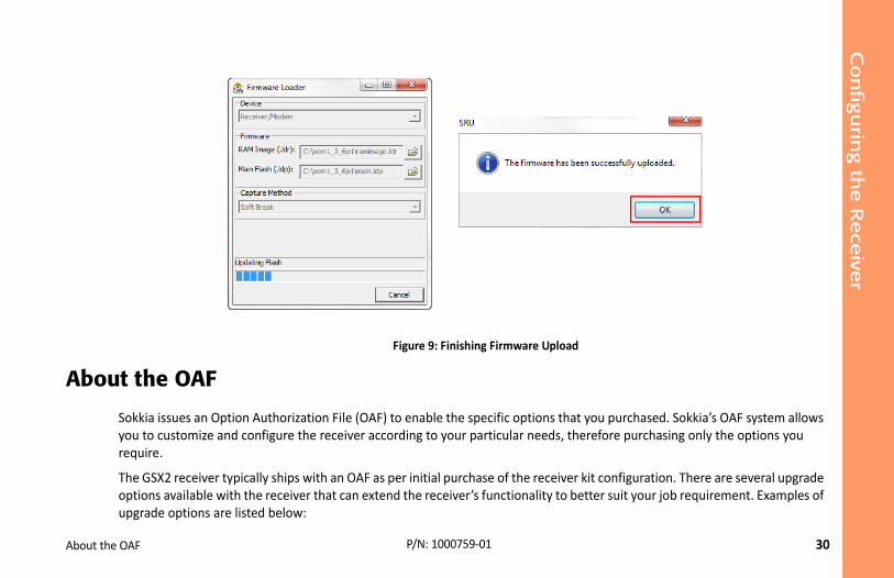
7. Click Start to upload the selected files.8. Click OK to continue uploading new firmware to the receiver (see F
Config
urin
g th
e R
ece
iver
30
Upload
ns that you purchased. Sokkia’s OAF system allows eds, therefore purchasing only the options you
ceiver kit configuration. There are several upgrade ty to better suit your job requirement. Examples of
About the OAF P/N: 1000759‐01
Figure 9: Finishing Firmware
About the OAF
Sokkia issues an Option Authorization File (OAF) to enable the specific optioyou to customize and configure the receiver according to your particular nerequire.
The GSX2 receiver typically ships with an OAF as per initial purchase of the reoptions available with the receiver that can extend the receiver’s functionaliupgrade options are listed below:
Config
urin
g th
e R
ece
iver
31
lable options and pricing information.
eceiver Utility (SRU) Reference Manual for more
ns window (Figure 10) displays, so you can view
About the OAF P/N: 1000759‐01
• GPS + GLONASS dual frequency static operation• Long‐Range Bluetooth base and rover RTK operation• Network RTK operation• RTK and update rate at 20 Hz
Contact your Sokkia dealer or a representative for a complete listing of avai
Checking the Receiver’s OAF
To use SRU to view the status of the receiver’s options:
1. Connect the receiver to a computer and open SRU. See the Sokkia Rinformation about connecting the receiver to a computer.
2. In SRU, connect to the receiver.
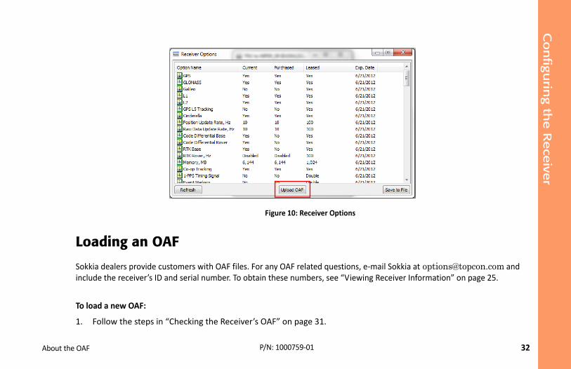
3. Click the Options icon in the main window. The Receiver Optiothe current authorization options and upload new ones.
Config
urin
g th
e R
ece
iver
32
ns
ons, e‐mail Sokkia at [email protected] and iewing Receiver Information” on page 25.
About the OAF P/N: 1000759‐01
Figure 10: Receiver Optio
Loading an OAF
Sokkia dealers provide customers with OAF files. For any OAF related questiinclude the receiver’s ID and serial number. To obtain these numbers, see “V
To load a new OAF:
1. Follow the steps in “Checking the Receiver’s OAF” on page 31.

Config
urin
g th
e R
ece
iver
33
ee Figure 10).e 11).
with the currently connected receiver. If you isplays an error icon next to the Receiver ID and
About the OAF P/N: 1000759‐01
2. Click Upload OAF on the bottom of the Receiver Options window (s3. Navigate to the location of the new Option Authorization File (Figur
Figure 11: Load OAF
4. Select the appropriate file, and click Open (Figure 11).Sokkia’s SRU initially checks to see if the selected file is compatible chose a file not intended for this receiver, the Upload OAF window ddisables the Upload the File to the Receiver button.

Config
urin
g th
e R
ece
iver
34
Check
e file. receiver to put new authorization options into
iver
About the OAF P/N: 1000759‐01
Figure 12: OAF Compatibility
5. Press Upload the File to the Receiver (Figure 12) to start loading thIf an OAF file is uploaded to the receiver, SRU will offer to reset theoperation (Figure 13).
Figure 13: Reset the Rece
6. Click Yes.
Config
urin
g th
e R
ece
iver
35
uired for satellite tracking, such as ephemeris data , such as active antenna input, elevation masks and . Clearing the receiver’s NVRAM restores the
ere are times when it can eliminate communication
erides and almanacs (around 15 minutes).
r’s memory, and the NVRAM keeps information
eceiver Utility (SRU) Reference Manual for more
Clearing the NVRAM P/N: 1000759‐01
Clearing the NVRAM
The receiver’s Non‐Volatile Random Access Memory (NVRAM) holds data reqand receiver position. The NVRAM also keeps the current receiver’s settingsrecording interval, and information about the receiver’s internal file systemreceiver’s factory default settings.
Although clearing the NVRAM is not recommended as a common practice, thor tracking problems.
After clearing the NVRAM, the receiver requires time to collect new ephem
Clearing the NVRAM will not delete any files already recorded in the receiveabout the receiver file system.
You can also use SRU to clear the NVRAM:
1. Connect the receiver to a computer, and open SRU. See the Sokkia Rinformation about connecting the receiver to a computer.
2. In SRU, connect to the receiver.
Config
urin
g th
e R
ece
iver
36
lear the NVRAM.
ox
Clearing the NVRAM P/N: 1000759‐01
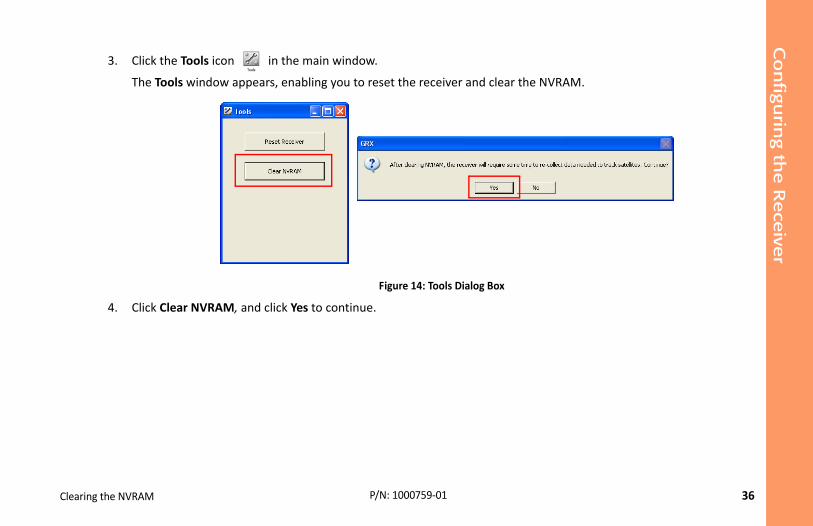
3. Click the Tools icon in the main window.
The Tools window appears, enabling you to reset the receiver and c
Figure 14: Tools Dialog B
4. Click Clear NVRAM, and click Yes to continue.
37
as during operation, allowing for a simplified setup
ly up to 300 meters using Long‐Range Bluetooth troller running SRU, MAGNET Field™, or Pocket‐3D
as a Long‐Range Base, network, RTK or Long‐Range
Field System Setup P/N: 1000759‐01
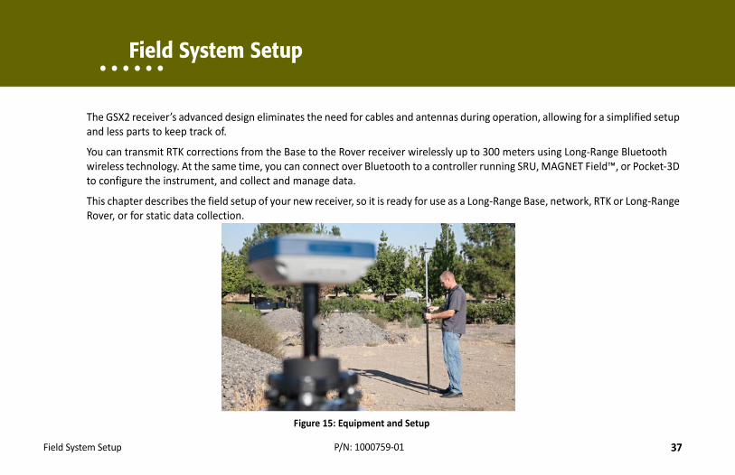
• • • • • • Field System Setup
The GSX2 receiver’s advanced design eliminates the need for cables and antennand less parts to keep track of.
You can transmit RTK corrections from the Base to the Rover receiver wirelesswireless technology. At the same time, you can connect over Bluetooth to a conto configure the instrument, and collect and manage data.
This chapter describes the field setup of your new receiver, so it is ready for useRover, or for static data collection.
Figure 15: Equipment and Setup

Field
Syste
m S
etu
p
38
Figure 16: Base Receiver
ipod
acer
rachpter
rach
iver
Setting Up the Base Receiver P/N: 1000759‐01
Setting Up the Base Receiver
1. Mount the receiver on a tripod with a tribrach, tribrach adapter, and prism spacer, as shown on the right.
2. Position the base system (from step 1) over a known point.
3. Level the tripod and measure the height of the receiver from the ground using the tape measure. See “Measuring Antenna Height” on page 40.
4. Press the power button to turn on the receiver. The integrated wireless device in the receiver turns on when the receiver is powered.
5. Connect the receiver to the Bluetooth‐enabled data collector, running Sokkia field software, to configure and start the base GSX2 receiver.
6. View the LED display panel for the receiver’s current status. See also “Display Panel Operations” on page 14.
Tr
Prism Sp
TribAda
Trib
Rece
Field
Syste
m S
etu
p
39
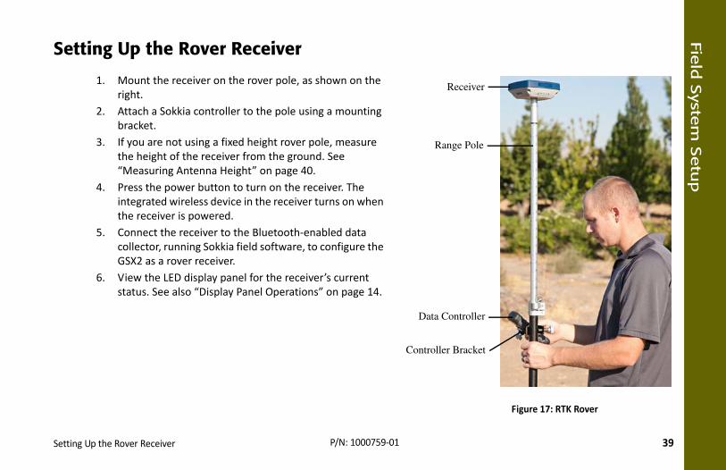
Figure 17: RTK Rover
Receiver
ange Pole
Controller
ler Bracket
Setting Up the Rover Receiver P/N: 1000759‐01
Setting Up the Rover Receiver
1. Mount the receiver on the rover pole, as shown on the right.
2. Attach a Sokkia controller to the pole using a mounting bracket.
3. If you are not using a fixed height rover pole, measure the height of the receiver from the ground. See “Measuring Antenna Height” on page 40.
4. Press the power button to turn on the receiver. The integrated wireless device in the receiver turns on when the receiver is powered.
5. Connect the receiver to the Bluetooth‐enabled data collector, running Sokkia field software, to configure the GSX2 as a rover receiver.
6. View the LED display panel for the receiver’s current status. See also “Display Panel Operations” on page 14.
R
Data
Control
Field
Syste
m S
etu
p
40
termine the coordinates of the station marker,
el, is automatically applied. This adjustment, when ows for correctly computed reference marker
er the slant height or the vertical height.ce Point (ARP) located at the bottom of the height to the Slant Height Measurement Mark he receiver, see Figure 18. notes.
Measuring Antenna Height P/N: 1000759‐01
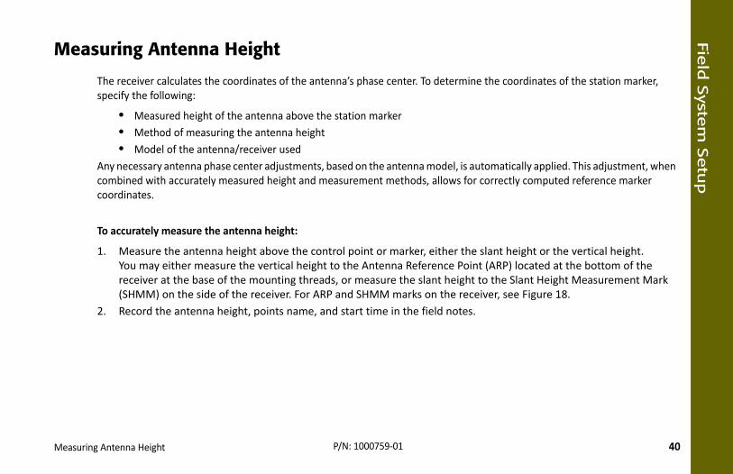
Measuring Antenna Height
The receiver calculates the coordinates of the antenna’s phase center. To despecify the following:
• Measured height of the antenna above the station marker• Method of measuring the antenna height• Model of the antenna/receiver used
Any necessary antenna phase center adjustments, based on the antenna modcombined with accurately measured height and measurement methods, allcoordinates.
To accurately measure the antenna height:
1. Measure the antenna height above the control point or marker, eithYou may either measure the vertical height to the Antenna Referenreceiver at the base of the mounting threads, or measure the slant (SHMM) on the side of the receiver. For ARP and SHMM marks on t
2. Record the antenna height, points name, and start time in the field

Field
Syste
m S
etu
p
41
oints
Measuring Antenna Height P/N: 1000759‐01
Figure 18: Antenna Height Measurement P
42
it, and removing files to free up internal memory.
ers, such as logging rate and types of messages, in on the GSX2 CD. See the SRU Reference Manual for onfiguration and recording raw data.
memory card. The amount of memory used to log rate parameters, see the SRU Reference Manual.
ia Receiver Utility (SRU) or MAGNET Office™
anel or SRU.
Collecting Data P/N: 1000759‐01
• • • • • • Collecting Data
This chapter provides general information about recording data, downloading
Setting Recording Parameters
The Sokkia Receiver Utility (SRU) software enables you to set logging parametwhich to record data. This software and the SRU Reference Manual is suppliedmore information. The GSX2 is compatible with any Sokkia field software for c
Logging Rates
The receiver provides up to 2 GB of file space on the internal (non‐removable)data depends on the logging rate. For more information about setting logging
Recording Data
You can log raw GNSS data to the receiver’s internal memory and use the Sokksoftware to download the files to a computer.
To start or stop recording data to the receiver, you can use the LED display p
1. Press the Power button to turn on the receiver.

Colle
cting D
ata
43
AT LED blinks green for GPS satellites and amber not solved a position. Five or more satellites
so select File ExplorerLogsStart in SRU to
as opened and data collection has started. The
imes, and make sure the REC LED is dark. You ding.0 seconds until all LEDs turn dark and the BAT
. Each file is recorded to the receiver’s internal f collected data can then be transferred to a RU), which is supplied on the Sokkia Receiver enter file names, and delete files as necessary. For
Managing Files P/N: 1000759‐01
2. Wait for the STAT LED to indicate satellites are being tracked. The STfor GLONASS satellites. A short red blink indicates the receiver hasprovide optimal positioning.
3. Press the POWER button three times to begin recording. You can albegin recording data.
4. Make sure the REC light is blinking green. This indicates that a file hREC LED blinks each time data is saved to the internal memory.
5. When you have finished recording, press the POWER button three tcan also select File ExplorerLogsStop in SRU to end data recor
6. To turn off the receiver, press and hold the POWER button for 3 to 1LED is solid red.
Managing Files
Raw data is recorded as time‐tagged measurements in a single raw data filememory, and automatically given a name and a *.tps file extension. A file ocomputer with file managing software, such as the Sokkia Receiver Utility (SUtilities CD. These programs allow you to use an automatic naming feature,more information, see the SRU Reference Manual supplied on the GSX2 CD.
You can also log data using MAGNET Field software.

Colle
cting D
ata
44
r for storage, post‐processing, or backup. The delete files to increase memory capacity.
C LED turns dark/off, indicating an error condition.
button for 15 to 20 seconds). This erases all of the
computer. In SRU, you can select the files you want information.puter or controller and then use the File Explorer re information about using SRU to download or on the GSX2 CD.
Managing Files P/N: 1000759‐01
Downloading and Deleting Files
After completing a survey, download data files to a computer or a controllereceiver’s internal memory holds a finite amount of files, so you will want to
When the internal memory is full, the receiver stops logging data, and the REExisting data is not overwritten.
There are two options for deleting raw data files from the receiver:
• Delete all of the files using the LED display panel (i.e. hold the powerfiles in the receivers internal memory.
• Use a USB, serial, or Bluetooth connection to download the files to ato delete from the receiver. See the SRU Reference Manual for more
Once a connection is established, you can download all or some files to a comfeature in Sokkia Receiver Utility (SRU) to manage the raw data files. For modelete files, see the Sokkia Receiver Utility (SRU) Reference Manual included

45
ay occur with the receiver.
owing:
secure connections. Double check for worn or
the power source is valid. See “Specifications” on
wnloaded onto the computer and the most current latest updates.bsite (www.sokkiasupport.com) for the latest
g SRU (ToolsReset receiver).
he warranty and may damage the hardware.
Troubleshooting P/N: 1000759‐01
• • • • • • Troubleshooting
This chapter will help you diagnose and solve some common problems that m
Check This First!
Before contacting your local dealer or Sokkia Technical Support, check the foll
• Check all external receiver connections carefully to ensure correct anddefective cables.
• Check the receiver’s internal batteries for a full charge.• Check the power source for incorrectly connected cables, and ensure
page 55 for external power requirements.• Check the software. Make sure the most current software version is do
firmware is loaded into the receiver. Check the Sokkia website for the • Check the Sokkia website (www.Sokkia.com) or the Sokkia Support we
updates.Then, try the following:
• Power on and off the receiver by pressing the Power button or by usin
Do not attempt to repair equipment yourself. Doing so will void t

Trouble
shootin
g
46
econds or using SRU (ToolsClear NVRAM). This d erases the almanac and ephemeris files. This
y using File ExplorerDelete All Files in SRU. This ard.
s.
age 22.ected or damaged.
ource, the receiver still does not power up, .
Powering Problems P/N: 1000759‐01
• Restore default settings by pressing the Power button for 10 to 15 srestores the receiver’s parameters to the factory default settings anaction does not delete data files from the receiver memory.
• Erase all files by pressing the Power button for 15 to 20 seconds or bwill delete all files stored in the receiver’s non‐removable memory c
If the problem persists, see the following sections for other solutions.
Powering Problems
The following are some of the most commonly encountered power problem
The receiver does not power up• The battery may be discharged.– Charge the battery overnight. See “Charging the Batteries” on p
• If you are using an external power source, the cable may be disconn– Make sure the cable is securely connected and undamaged.
• The receiver may have a defective charger or defective battery.– If, after changing the battery or connecting an external power scontact your local dealer or Sokkia Technical Support for advice

Trouble
shootin
g
47
ms.
roller
e receiver.
.
er, included on the GPS+ Software CD, is m the Sokkia Support website at
onnection” in the Sokkia Receiver Utility (SRU)
o cmd.
Receiver Problems P/N: 1000759‐01
Receiver Problems
The following are some of the most commonly encountered receiver proble
The receiver cannot establish a connection to a computer or external contCable specific problems:
• The cable is not properly plugged in.– Unplug the cable, then securely and properly reconnect it to th
• The cable is damaged.– Use an undamaged cable. Contact a dealer to replace the cable
• The USB driver is not installed.– If you are using a USB cable connection, make sure the USB drivinstalled on the computer. You can also download the driver frowww.sokkiasupport.com.
Generic problems:
• The receiver port used for connection is not in Command mode.a. Connect the receiver to a computer and open SRU (see “C
Reference Manual).
b. Click Receiver SettingsPorts.
c. Change the Input Mode for the port used for connection t

Trouble
shootin
g
48
L2, GPS/GLONASS must be on to track satellites).r extend validity of the corresponding receiver .r Utility (SRU) Reference Manual for a detailed
gs, and so forth).
onnection” in the Sokkia Receiver Utility (SRU)
kingAdv tab. Make sure the C/A code
ection. “line‐of‐sight” path to the Rover.
Receiver Problems P/N: 1000759‐01
The receiver does not lock on to satellites for a long period of time
• The corresponding receiver options may be disabled or expired (L1/– Order a new OAF with the desired options activated to enable ooptions. Contact a dealer or visit the Sokkia website for details
– Refer to the “Receiver Managing” chapter of the Sokkia Receivedescription of options.
The receiver tracks too few satellites• The survey is conducted near obstructions (tree canopy, tall buildin– Make sure the Multipath Reduction boxes have been enabled.
a. Connect the receiver to a computer and open SRU (see “CReference Manual).
b. In SRU, connect to the receiver.
c. On the SRU main window, choose Receiver SettingsTracmultipath reduction check box is selected.
• Move to an area free of obstructions, if applicable.
The receiver cannot obtain Code Differential and/or RTK solutions• Incorrect Base coordinates entered.– Specify the correct coordinates for the Base station using SRU or another suitable field data collection software.
• There could be some obstruction to the Long‐Range Bluetooth conn– Clear all possible obstructions or relocate the Base so there is a

Trouble
shootin
g
49
or extend validity of the corresponding receiver
a detailed description of options.solution, the Base and Rover should track at least
y should be the same. To do this, on the SRU
tracking. Base and Rover receivers.nput/output format:
onnection” in the Sokkia Receiver Utility (SRU)
s.
he input mode of the Rover matches the format
wer PDOP value).
tooth, network, and Network and Long‐Range available options to purchase with the
Receiver Problems P/N: 1000759‐01
• The corresponding receiver options may be disabled or expired.– Order a new OAF with the required options activated to enableoptions.
– Refer to the Sokkia Receiver Utility (SRU) Reference Manual for• There are not enough common satellites. In order to obtain a fixed
five common satellites.– Check the elevation masks of the Rover and Base receivers; themain window, choose Receiver SettingsTrackingObs.
– Verify there is a clear view of the sky to allow sufficient satellite• A discrepancy exists between the differential standards used at the– Ensure the Base and Rover receivers use the same corrections i
a. Connect the receiver to a computer and open SRU (see “CReference Manual).
b. In SRU, connect to the receiver.
c. On the SRU main window, choose Receiver SettingsPort
d. Double‐click on the port to be configured and make sure tof the Base output mode (i.e. RTCM3).
• Poor satellite geometry (PDOP/GDOP values are too high).– Survey during a time period when satellite visibility is better (lo
The GSX2 receiver requires different OAFs for Long‐Range BlueBluetooth operations. Contact a Sokkia dealer for details aboutreceiver.
Trouble
shootin
g
50
d click Receiver SettingsTrackingObs.
, choose Receiver SettingsTrackingObs. tracking.munications.
o antennas (if possible).
okkia Receiver Utility (SRU) Reference Manual.
s. See “Downloading and Deleting Files” on
Long‐Range Bluetooth Problems P/N: 1000759‐01
– Increase the PDOP threshold using SRU. To do this, open SRU an– Ensure the elevation mask is less than 15 degrees.
• The elevation mask is above 15 degrees.– Lower the elevation mask. To do this, on the SRU main window– Verify there is a clear view of the sky to allow sufficient satellite
• There may be a source of radio interference that disrupts radio com– Change the RF channel (if possible).– Removing the source of the jamming signal or relocate the radi
The receiver does not start logging data • The receiver’s memory is disabled or expired.– Make sure the memory option is enabled. For details, see the S
• The receiver’s internal memory card does not have free space.– Download and/or delete data files to free up space for new filepage 44.
Long-Range Bluetooth Problems
The following are some of the most commonly encountered problems.
Long‐Range Bluetooth cannot discover the Base receiver
• The Base is out of range.– Make sure the Base receiver is within 300 meters of the Rover.

Trouble
shootin
g
51
luetooth LEDs are blue on both receivers).
. 3 connections are already established.)
and other problems.
Power button for 10 to 15 seconds.
location.
Bluetooth Problems P/N: 1000759‐01
• The Base is not responding.– Make sure the Base is turned on.
• Make sure Bluetooth is turned on for the Base and Rover (i.e. the B• Make sure there are no obstructions or interference.
A Bluetooth connection cannot be established
• A Long‐Range Bluetooth connection is not available at the Base. (i.e• Make sure there are no obstructions or interference.
Bluetooth Problems
The following are some of the most commonly encountered error messages
SRU error message: Can’t find receiver
• The receiver is turned off.– Ensure the receiver has power and is turned on.
• Bluetooth is not turned on; the BT LED is off.– Reset the receiver to the factory default settings by pressing the
• There is interference.– Move the receiver, controller, or computer to an unobstructed
• The receiver is too far away.– Move the devices closer together.
• The receiver is already connected via Bluetooth to another device.

Trouble
shootin
g
52
onnection” in the Sokkia Receiver Utility (SRU)
for connection to cmd.
on.
tooth connections to computers or controllers.
to double check the settings for the
Bluetooth Problems P/N: 1000759‐01
– Disconnect the receiver from the other controller or computer.
• The receiver port used for connection is not in Command mode.a. Connect the receiver to a computer and open SRU (see “C
Reference Manual).
b. Click ConfigurationReceiverPorts.
c. Change the Input Mode for the Bluetooth serial port used
SRU error message: Open COM# port failed: Access is denied• Another application uses the computer port dedicated for connecti– Close the application, and then re‐connect.– Connect the receiver via another, unused computer port.
Long‐Range Bluetooth connections will not interfere with Blue
This is the most common cause for this error message. Use SRUconnection port.

Trouble
shootin
g
53
e receiver.ew cable.
en, but cannot connect to it
settings.
ve it from the list of discovered Bluetooth ith the device used to manage the receiver).
SRU Problems P/N: 1000759‐01
After searching for available devices, none are discovered
• The receiver is not receiving power.– Check that the receiver is getting power and is turned on.– Check that the power cable is correctly attached to the port.– Unplug the cable, then securely and properly reconnect it to th– If the power cable is damaged, contact a Dealer to purchase a n
Can see the icon for the receiver’s Bluetooth module on the computer scre
• Device security settings probably differ.– Make sure the Bluetooth enabled devices use the same security
• Bluetooth module settings may have changed.a. If the settings are changed for the Bluetooth module, remo
devices using the Bluetooth manager program (supplied w
b. Repeat the search.
SRU Problems
The following is the most commonly encountered SRU problem.
SRU cannot connect to the receiver• The receiver is turned off.– Ensure the receiver has power and is turned on.
• If using a cable, the cable’s connectors are improperly attached.
Trouble
shootin
g
54
port. e receiver.
.ogy enabled/installed.communication. For the GSX2 receiver, this is
, which are available on the Sokkia Receiver Utility
ents.ry any moisture with a soft, clean cloth.
the problem, contact Sokkia Customer Support. For
Cleaning and Storing the Receiver P/N: 1000759‐01
– Check that the cable connector is attached to the correct serial– Unplug the cable, then securely and properly reconnect it to th
• If using a cable, the cable is damaged.– Use an undamaged cable.– Contact a dealer to purchase a new cable.
• If using Bluetooth wireless technology, the incorrect port is selected– Use a computer or receiver that has Bluetooth wireless technol– Make sure the computer and receiver use the correct ports for Bluetooth serial port A (btsp\a).
• If using a USB is cable, make sure the USB drivers have been installedCD.
Cleaning and Storing the Receiver
• Use a clean cloth moistened with neutral detergent or water.• Never use an abrasive cleaner, ether, thinner benzene, or other solv• Always make sure the receiver is completely dry before storing it. D
Getting Customer Support
If the troubleshooting hints and tips in this operator’s manual fail to remedy contact information, see “Getting Technical Support” on page 7.
55
wireless technology for small job site operations receiver and its internal components.
Specifications P/N: 1000759‐01
• • • • • • Specifications
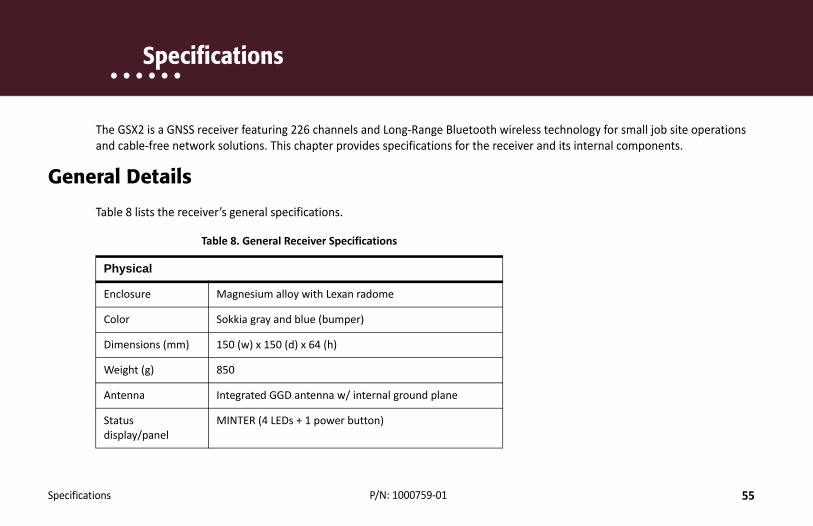
The GSX2 is a GNSS receiver featuring 226 channels and Long‐Range Bluetoothand cable‐free network solutions. This chapter provides specifications for the
General Details
Table 8 lists the receiver’s general specifications.
Table 8. General Receiver Specifications
Physical
Enclosure Magnesium alloy with Lexan radome
Color Sokkia gray and blue (bumper)
Dimensions (mm) 150 (w) x 150 (d) x 64 (h)
Weight (g) 850
Antenna Integrated GGD antenna w/ internal ground plane
Status display/panel
MINTER (4 LEDs + 1 power button)

Specifica
tions
56
General Details P/N: 1000759‐01Serial/External Power
Hirose H205‐Series (6‐pin, multiplex)
USB USB Mini B 2.0 (client)
External antenna connector
None
Bluetooth antenna Fully integrated, high‐sensitivity
Tracking
Number of Channels
226 universal channels
Tracked Signalsa GPS: L1 C/A, L1, L2P(Y), L2, L2C code and carrierGLONASS: L1 C/A, L1P, L2 C/A, L2P code and carrier
SBAS WAAS/EGNOS/MSAS/QZSS) L1 code and carrier
Multipath reduction
Yes, code and carrier
PLL/DLL setting Adjustable bandwidth and order
Smoothing interval Adjustable, code and carrier
Data Output
RTK Corrections TPS, RTCM SC104 v 2.x, 3.x; CMR/CMR+b
Table 8. General Receiver Specifications

Specifica
tions
57
General Details P/N: 1000759‐01ASCII Output NMEA 0183 version 2.x and 3.x
RTK position data rate (max.)
20 Hz
Measurement data rate (max.)
20 Hzc
Data and Memory
Removable media None
Internal memory 2 GB
Message storage rate (max.)
20 Hz
Environment
Operating temperature
‐20°C to +65°C (batteries) ‐40°C to +65°C (w/ external power)
Storage temperature
‐40°C to +70°C
Humidity 100%, condensing
Waterproof rating IPX7 (1 meter submersion)
Dust rating IP6X (Fully dust proof)
Table 8. General Receiver Specifications

Specifica
tions
58
s.
ut
l
General Details P/N: 1000759‐01
Random vibration MIL‐STD 202G, Method 214A, Test Curve A, 5.35g RMS
Sinusoidal vibration SAE J1211:1978 Section 4.7, 4g Peak
Shock IEC 60068‐2‐27 edition 4, Table A.225g, 6ms
Topple 2.0m pole drop
Power
Internal Batteries 7.4 V, 5000 mAh
Battery charging time
<5 hours
Battery charging method
Connect the AC adaptor to charge the internal batterieAvailable run charge when connected to an external battery. Charging of internal batteries when power inpis greater than 12 V.
Operating time >15 hrs (RTK Rover with Long‐Range Bluetooth, internabatteries, 20° C)
External power input
6.5 to 30 VDCd
Power consumption
2.0 W (RTK Rover with Long‐Range Bluetooth, using internal batteries at 20° C)
Table 8. General Receiver Specifications

Specifica
tions
59
e.
General Details P/N: 1000759‐01
External power supply adapter rating
Input: 100‐240 VAC, 50‐60 Hz, 0.8AOutput: +12VDC/2.5A
Communication
Serial 1 port; Hirose H205‐Series (6‐pin, multiplex); RS232 RX/TX
USB 1 port; USB Mini B 2.0 (client)
LongLINK™ wireless 3 simultaneous connections
Bluetooth v2.1 + EDR
Cellular Yes. Via external Bluetooth‐enabled controller or devic
Survey Accuracye
Static, fast‐static (post‐processed)
L1 only: H: 3 mm + 0.8 ppm (x baseline distance) V: 4 mm + 1 ppm (x baseline distance)
L1 +L2: H: 3 mm + 0.5 ppm (x baseline distance) V: 5 mm + 0.5 ppm (x baseline distance)
Table 8. General Receiver Specifications
Specifica
tions
60
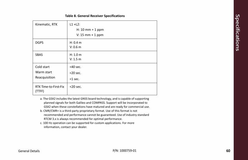
General Details P/N: 1000759‐01Kinematic, RTK L1 +L2:H: 10 mm + 1 ppm V: 15 mm + 1 ppm
DGPS H: 0.4 mV: 0.6 m
SBAS H: 1.0 mV: 1.5 m
Cold startWarm startReacquisition
<40 sec.
<20 sec.
<1 sec.
RTK Time‐to‐First‐Fix (TTFF)
<20 sec.
a. The GSX2 includes the latest GNSS board technology, and is capable of supporting planned signals for both Galileo and COMPASS. Support will be incorporated to GSX2 when these constellations have matured and are ready for commercial use.
b. CMR/CMR+ is a third‐party proprietary format. Use of this format is not recommended and performance cannot be guaranteed. Use of industry standard RTCM 3.x is always recommended for optimal performance.
c. 100 Hz operation can be supported for custom applications. For more information, contact your dealer.
Table 8. General Receiver Specifications

Specifica
tions
61
General Details P/N: 1000759‐01d. 6.5 to 30 VDC is the operating range of the external power source when the receiver is on. To turn the receiver on, the power input must be between 8 to 30 VDC. To charge the internal batteries, the external power input must be greater than 12 VDC.
e. Accuracy will vary depending on the number of satellites used, obstructions, satellite geometry (PDOP), occupation time, multipath effects, and atmospheric conditions. Performance may be degraded in conditions with high Ionospheric activity, extreme multipath, or under dense foliage. For maximum system accuracy, always follow best practices for GNSS data collections.
62
etween the user and the receiver when
is, surveying coordinates, distances, angles and ver be used:
Safety Warnings P/N: 1000759‐01
• • • • • • Safety Warnings
General Warnings
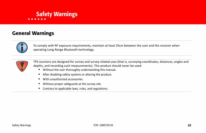
To comply with RF exposure requirements, maintain at least 25cm boperating Long‐Range Bluetooth technology.
TPS receivers are designed for survey and survey related uses (that depths, and recording such measurements). This product should ne
• Without the user thoroughly understanding this manual.• After disabling safety systems or altering the product.• With unauthorized accessories.• Without proper safeguards at the survey site.• Contrary to applicable laws, rules, and regulations.

Safe
ty Warn
ings
63
orized technicians will void the receiver’s
internal components.
without proper packaging, or otherwise
des accurate measurements.y.
e or repair this product.
Receiver Warnings P/N: 1000759‐01
Receiver Warnings
Usage Warnings
Tampering with the receiver by the end users or non‐factory authwarranty:
• Do not attempt to open the receiver and modify any of its• Do not charge in conditions different than specified.• Do not short circuit.
If this product has been dropped, altered, transported or shippedtreated without care, erroneous measurements may occur.The owner should periodically test this product to ensure it proviInform TPS immediately if this product does not function properl
Only allow authorized Sokkia warranty service centers to servic
64
government regulations for use.
ntrolled equipment and meets the FCC radio t has very low levels of RF energy that it deemed to irable that it should be installed and operated with tremities: hands, wrists, feet and ankles).
A digital device pursuant to part 15 of the FCC rules. erference when the equipment is operated in a io frequency energy and, if not installed and used adio communications. Operation of this equipment er will be required to correct the interference at his
eption, which can be determined by turning the e by one or more of the following measures:
Regulatory P/N: 1000759‐01
• • • • • • Regulatory
The following sections provide information on this product’s compliance with
FCC Compliance
This equipment complies with FCC radiation exposure limits set forth for uncofrequency (RF) Exposure Guidelines in Supplement C to OET65. This equipmencomply without maximum permissive exposure evaluation (MPE). But it is desat least 20cm and more between the radiator and person’s body (excluding ex
This equipment has been tested and found to comply with the limits for a Class These limits are designed to provide reasonable protection against harmful intcommercial environment. This equipment generates, uses, and can radiate radin accordance with the instruction manual, may cause harmful interference to rin a residential area is likely to cause harmful interference in which case the usown expense.
If this equipment does cause interference to radio or television equipment recequipment off and on, the user is encouraged to try to correct the interferenc
• Reorient or relocate the receiving antenna.• Move the equipment away from the receiver.
Regula
tory
65
which the receiver is powered. additional suggestions.
B-003 du Canada.
tandard(s). Operation is subject to the ce, and (2) this device must accept any ation of the device.
plicables aux appareils radio exempts de : (1) l’appareil ne doit pas produire de ilage radioélectrique subi, même si le
pproved by the party responsible for nt.
Industry Canada Compliance P/N: 1000759‐01
• Plug the equipment into an outlet on a circuit different from that to• Consult the dealer or an experienced radio/television technician for
Industry Canada Compliance
This class A digital apparatus complies with Canadian ICES-003.Cet appareil numérique de la classe A est conforme à la norme NM
This device complies with Industry Canada licence-exempt RSS sfollowing two conditions: (1) this device may not cause interfereninterference, including interference that may cause undesired oper
Le présent appareil est conforme aux CNR d’Industrie Canada aplicence. L’exploitation est autorisée aux deux conditions suivantesbrouillage, et (2) l’utilisateur de l’appareil doit accepter tout broubrouillage est susceptible d’en compromettre le fonctionnement.
Any changes or modifications to the equipment not expressly acompliance could void your authority to operate such equipme

Regula
tory
66
MC directives from the European Community.
ormity with R&TTE Directive
ct may cause radio interference in which case
Community of Europe Compliance P/N: 1000759‐01
Community of Europe Compliance
The product described in this manual is in compliance with the R&TTE and E
European Community Declaration of Conf1999/5/EC
The following standards were applied: (R&TTE Directive 1999/5/EEC)
• EN 301 489‐1 V1.8.1 (2008‐04)• EN 301 489‐17 V2.1.1 (2009‐05)• EN 300 328 V1.7.1 (2006‐10)• EN 60950‐1: 2006 + A11:2009/A1:2010• EN 301 489‐3 V1.4.1 (2002‐08)• EN 300 440‐2 V1.4.1
The following CE mark is affixed to the device:
This is a Class A product. In a domestic environment this produthe user may be required to take adequate measures.

Regula
tory
67
99/5/EC)
od se eními smrnice
e udstyr levante krav i
) in ungen und den 1999/5/EG
tavust direktiivi lenevatele
mpliance with isions of
SX2) cumple isposiciones
Declaration of Conformity (R&TTE Directive 1999/5/EC) P/N: 1000759‐01
Declaration of Conformity (R&TTE Directive 19
esky [Czech]
(Sokkia) tímto prohlašuje, že tento (GSX2) je ve shzákladními požadavky a dalšími píslušnými ustanov1999/5/ES.
Dansk [Danish]
Undertegnede (Sokkia) erklærer herved, at følgend(GSX2) overholder de væsentlige krav og øvrige redirektiv 1999/5/EF.
Deutsch [German]
Hiermit erklärt (Sokkia) dass sich das Gerät (GSX2Übereinstimmung mit den grundlegenden Anforderübrigen einschlägigen Bestimmungen der Richtliniebefindet.
Eesti [Estonian]
Käesolevaga kinnitab (Sokkia) seadme (GSX2) vas1999/5/EÜ põhinõuetele ja nimetatud direktiivist tuteistele asjakohastele sätetele.
English Hereby, (Sokkia) declares that this (GSX2) is in cothe essential requirements and other relevant provDirective 1999/5/EC.
Español [Spanish]
Por medio de la presente (Sokkia) declara que el (Gcon los requisitos esenciales y cualesquiera otras daplicables o exigibles de la Directiva 1999/5/CE.
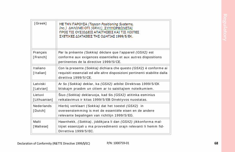
Regula
tory
68
X2) est dispositions
) è conforme ai ti stabilite dalla
999/5/EK miem.
sminius as.
andere
forma mal-i li hemm fid-
Declaration of Conformity (R&TTE Directive 1999/5/EC) P/N: 1000759‐01
[Greek]
Français [French]
Par la présente (Sokkia) déclare que l'appareil (GSconforme aux exigences essentielles et aux autres pertinentes de la directive 1999/5/CE.
Italiano [Italian]
Con la presente (Sokkia) dichiara che questo (GSX2requisiti essenziali ed alle altre disposizioni pertinendirettiva 1999/5/CE.
Latviski [Latvian]
Ar šo (Sokkia) deklar, ka (GSX2) atbilst Direktvas 1btiskajm prasbm un citiem ar to saisttajiem noteiku
Lietuvi [Lithuanian]
Šiuo (Sokkia) deklaruoja, kad šis (GSX2) atitinka ereikalavimus ir kitas 1999/5/EB Direktyvos nuostat
Nederlands [Dutch]
Hierbij verklaart (Sokkia) dat het toestel (GSX2) inovereenstemming is met de essentiële eisen en derelevante bepalingen van richtlijn 1999/5/EG.
Malti [Maltese]
Hawnhekk, (Sokkia), jiddikjara li dan (GSX2) jikkontiijiet essenzjali u ma provvedimenti orajn relevantDirrettiva 1999/5/EC.
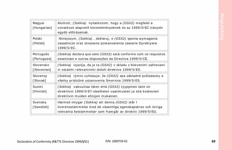
Regula
tory
69
gfelel a 5/EC irányelv
ymagania yrektywie
m os requisitos /CE.
nimi zahtevami .
požiadavky a
ite on koskevien
av och övriga 999/5/EG.
Declaration of Conformity (R&TTE Directive 1999/5/EC) P/N: 1000759‐01
Magyar [Hungarian]
Alulírott, (Sokkia) nyilatkozom, hogy a (GSX2) mevonatkozó alapvetõ követelményeknek és az 1999/egyéb elõírásainak.
Polski [Polish]
Niniejszym, (Sokkia) , deklaruj, e (GSX2) spenia wzasadnicze oraz stosowne postanowienia zawarte D1999/5/EC.
Português [Portugues]
(Sokkia) declara que este (GSX2) está conforme coessenciais e outras disposições da Directiva 1999/5
Slovensko [Slovenian]
(Sokkia) izjavlja, da je ta (GSX2) v skladu z bistvein ostalimi relevantnimi doloili direktive 1999/5/ES
Slovensy [Slovak]
(Sokkia) týmto vyhlasuje, že (GSX2) spa základnévšetky príslušné ustanovenia Smernice 1999/5/ES.
Suomi [Finnish]
(Sokkia) vakuuttaa täten että (GSX2) tyyppinen ladirektiivin 1999/5/EY oleellisten vaatimusten ja sitädirektiivin muiden ehtojen mukainen.
Svenska [Swedish]
Härmed intygar (Sokkia) att denna (GSX2) står I överensstämmelse med de väsentliga egenskapskrrelevanta bestämmelser som framgår av direktiv 1
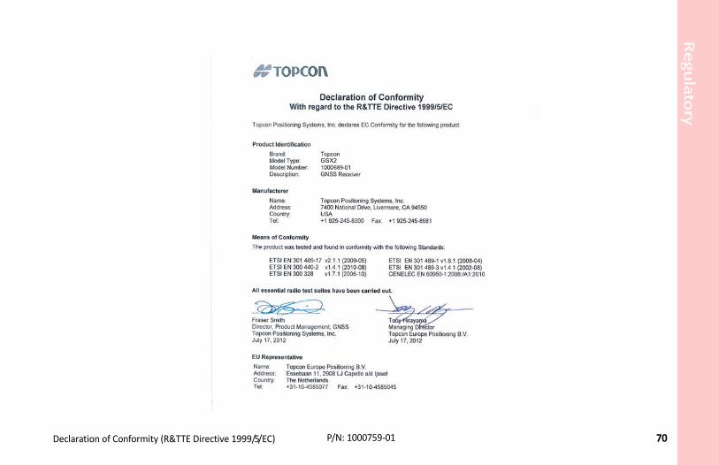
Regula
tory
70
Declaration of Conformity (R&TTE Directive 1999/5/EC) P/N: 1000759‐01GSX2689

Regula
tory
71
as household waste. By ensuring this product is he environment and human health, which could ore detailed information about the take‐back and product or consult.
ce
version 2.1/2.1+EDR:
he Bluetooth qualification is valid for any antenna
WEEE Directive P/N: 1000759‐01
WEEE Directive
Following information is for EU‐member states only:
The use of the symbol below indicates that this product may not be treateddisposed of correctly, to help prevent potential negative consequences for totherwise be caused by inappropriate waste handling of this product. For mrecycling of this product, please contact a supplier where you purchased the
Bluetooth Transmission Statements/Complian
This Bluetooth device is compliant to the following profiles of the core spec
• Baseband• HCI• Link Manager• Radio
The radio has been tested using the maximum antenna gain of 2.3 dBi and twith the same or less gain.

Regula
tory
72
련된 서비스는 할 수 없습니다 .
-01, Inc.e with Bluetooth radio
igin): PC Partner, China
는 이 점을 주의하시기 바라며 ,
Korean KC‐RF Compliance P/N: 1000759‐01
Korean KC-RF Compliance
해당 무선설비는 전파혼신 가능성이 있으므로 인명안전과 관
무선사양 (Wireless specification): Bluetooth 2.1 + EDR사용주파수 (Used Frequency): 2402-2480 MhZ채널 수 (the number of channels): 79공중선전력 (Antenna Power): 2.1 dBi변조방식 (Type of the modulation): GFSK, 8PSK
인증정보 (Product Id Code): KCC-CRM-T8S-1000036신청자 (Applicant): Topcon Positioning Systems기기명칭 (Type of equipment): GPS surveying devic모델 이름 (Model Name): GSX2 or GSX2제조연월 (Year of manufacture): 2012제조자 및 제조국가 (Manufacturer and country of or인증자 식별 부호 (Applicant Code): T8S
Korean KC-EMC Class A Statement이 기기는 업무용 (A 급 ) 전자파 적합기기로서 판매자 또는 사용자
가정외의 지역에서 사용하는 것을 목적으로 합니다 .

73
ve correction information for nearby Rover (mobile)
logy for exchanging data over short distances from
hina.
European Union (EU) and European Space Agency
by the Russian Federation.
tates Department of Defense.
Glossary P/N: 1000759‐01
• • • • • • Glossary
B
Base Station – A GNSS receiver set up over a known point, which is used to deriGNSS receivers.
Bluetooth® – Often used in place of cables, Bluetooth is open wireless technofixed and mobile devices.
C
COMPASS – BeiDou Navigation Satellite System maintained and operated by C
G
GALILEO – The satellite system currently being maintained and operated by the(ESA).
GGD – GPS + GLONASS Dual Frequency signal tracking.
GLONASS – The GLObal NAvigation Satellite System maintained and operated
GNSS – Global Navigation Satellite Systems, such as GPS and GLONASS.
GPS – The Global Positioning System maintained and operated by the United S

Glo
ssary
74
smit satellite data.
ansmit satellite data.
lay the status of the receiver’s components and
vides short‐range RTK communication up to 1,000
ware system.
g and grade application. It is part of the MAGNET
ta input and output.
ithin the network and sends RTK corrections to the
ustomer purchases.
P/N: 1000759‐01
L
L1 – The primary L‐band carrier used by GPS and GLONASS satellites to tran
L2 – The secondary L‐band carrier used by GPS and GLONASS satellites to tr
Light‐Emitting Diode (LED) – Used as indicator lights on the receiver to dispcontrol receiver operations.
Long‐Range Bluetooth – Sokkia’s Long‐Range Bluetooth RTK technology proft. (300m from the Base station).
M
MAGNET Field™ – Data controller software that is part of the MAGNET soft
MAGNET Office™ – Post‐processing and CAD solution software for surveyinsoftware system.
MINTER – The receiver’s Minimum INTERface used to display and control da
N
Network RTK – Collects satellite observations from the reference stations wRover.
O
Option Authorization File (OAF) – This enables the specific features that a c
Glo
ssary
75
ion spreads spherically outward, with the phase of
enables you to check the measurement quality
g quantity.
ation in the field.
al navigation systems. SBAS transmits differential network or reference stations in a wide area, such
ositioning. This method provides the highest
rs and peripheral devices. SRU is included on the
P/N: 1000759‐01
P
Phase Center of Antenna – The point from which the electromagnetic radiatthe signal being equal at any point on the sphere.
Pocket‐3D – Field controller software that supports both GNSS and TS.
R
Real‐Time Kinematic (RTK) – A precise method of real‐time surveying. RTK without having to process the data.
Root Mean Square (RMS) – Statistical measure of the magnitude of a varyin
Rover – A mobile GNSS receiver and data collector used for determining loc
S
Satellite‐Based Augmentation Systems (SBAS) – Complements existing globcorrections and messages for navigation satellites that are within sight of a as a continent.
Static Survey – Typically uses a network or multiple baseline approach for paccuracy and requires the longest observation times.
Sokkia Receiver Utility (SRU) – Hardware configuration software for receiveSokkia Receiver Utility CD that accompanied your receiver.

Glo
ssary
76
s a receiver, controller, computer, etc.
P/N: 1000759‐01
U
Universal Serial Bus (USB) – A connection standard used by devices, such a
