gt lts disk brakes-
TRANSCRIPT
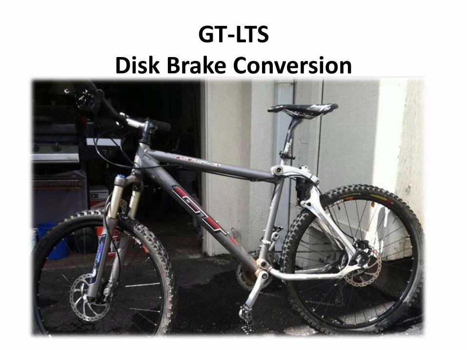
GT-LTS Disk Brake Conversion

Supplies needed
• Complete Disk Brake Kit• Universal rear disk
brake mounting purchased at e-Bay.
• http://www.ebay.com/itm/350494596169?ssPageName=STRK:MEWNX:IT&_trksid=p3984.m1497.l2649
• This seller advertises two different models. I purchased the adapter that is for bike frames that do NOT have the pre-existing mounting holes. The bracket is a tad larger than the other option.

Following is a list of items I purchased at the local Home Depot store.
1- shelf bracket, portion of this bracket will be used for the forward pressure support arm.
3 - 5.8mm hex bolts 20 mm long with appropriate nuts3 - 6.1mm hex bolts 20 mm long with appropriate nuts2 - 2 mm washer
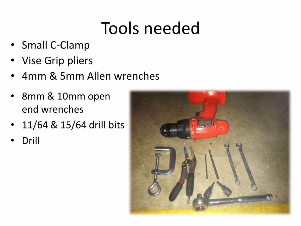
Tools needed
• 8mm & 10mm open end wrenches
• 11/64 & 15/64 drill bits
• Drill
• Small C-Clamp
• Vise Grip pliers
• 4mm & 5mm Allen wrenches
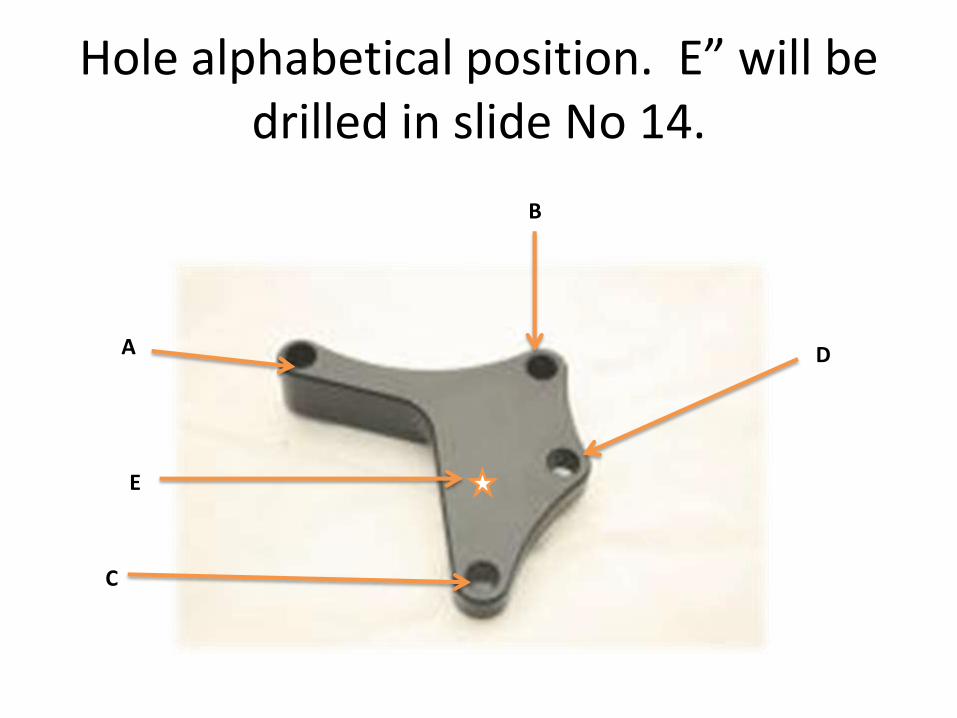
Hole alphabetical position. E” will be drilled in slide No 14.
A
B
D
C
E
The Universal kit does not have a template of where to drill the holes on the bicycle frame. You have to find the sweet spot where the caliper fits perfect, and that’s when you drill the frame. After-all, you don’t want start drilling holes without being sure of where the bracket will go and end up with a frame full of holes.

Assemble your caliper to the universal mounting bracket, make sure all bolts
are tight (do not torque).
Make sure you install your wheel on the bike.
Place the caliper over the brake disk and try to find the exact spot where the wheel will rotate with the least amount of resistance.
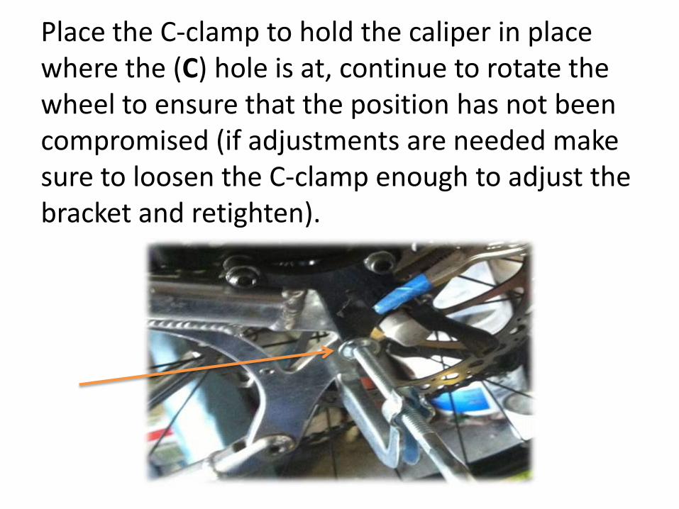
Place the C-clamp to hold the caliper in place where the (C) hole is at, continue to rotate the wheel to ensure that the position has not been compromised (if adjustments are needed make sure to loosen the C-clamp enough to adjust the bracket and retighten).
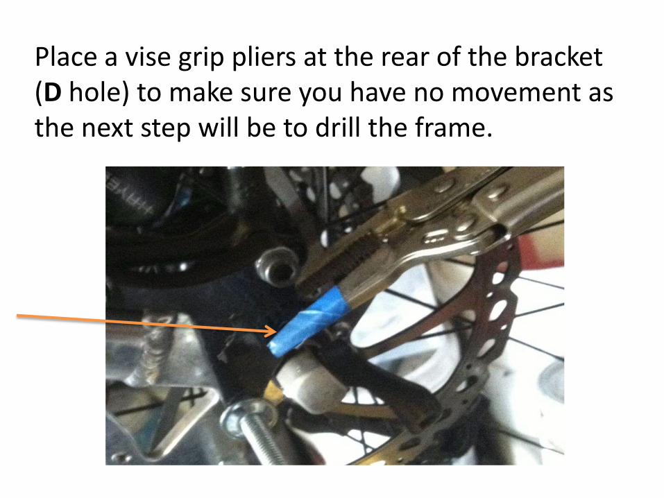
Place a vise grip pliers at the rear of the bracket (D hole) to make sure you have no movement as the next step will be to drill the frame.
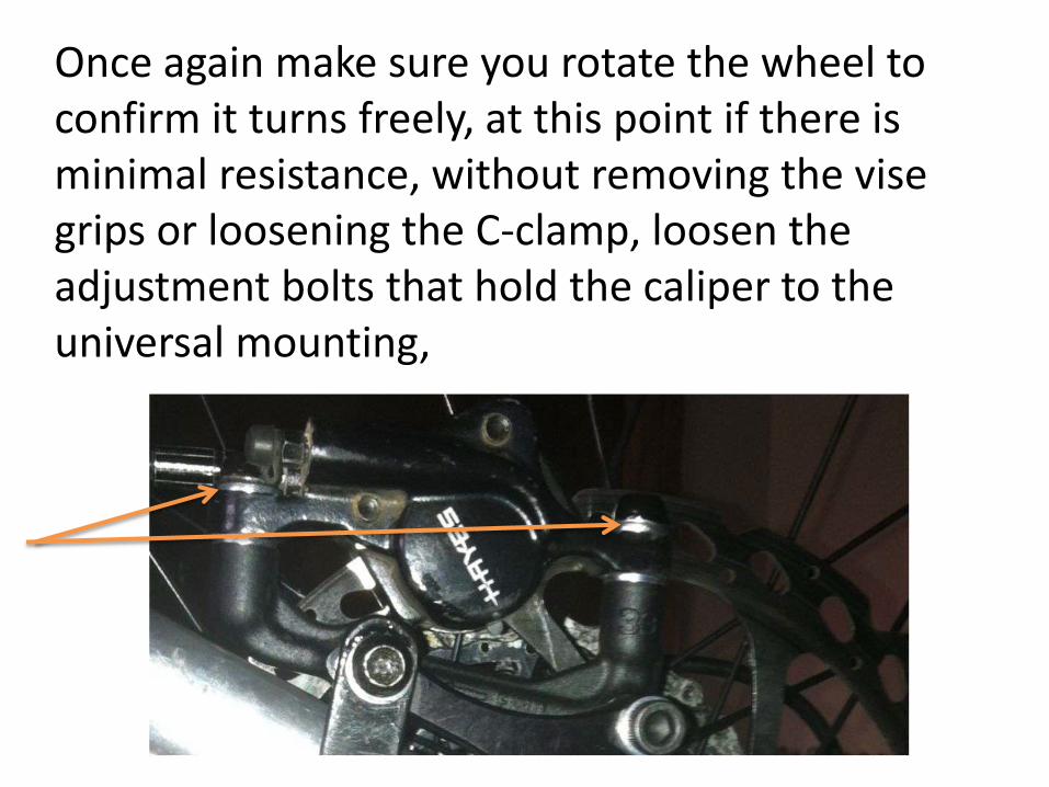
Once again make sure you rotate the wheel to confirm it turns freely, at this point if there is minimal resistance, without removing the vise grips or loosening the C-clamp, loosen the adjustment bolts that hold the caliper to the universal mounting,
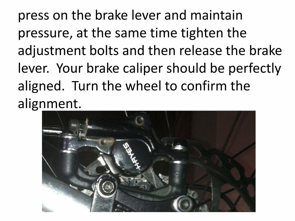
press on the brake lever and maintain pressure, at the same time tighten the adjustment bolts and then release the brake lever. Your brake caliper should be perfectly aligned. Turn the wheel to confirm the alignment.
Extreme Caution should be taken on the next steps as you
will now be drilling your hard to replace frame Triangle.
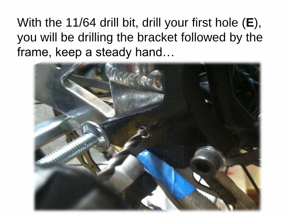
With the 11/64 drill bit, drill your first hole (E),
you will be drilling the bracket followed by the
frame, keep a steady hand…
(The reason for this hole is that the position of the outer hole (D) is right at the edge of the frame and with the amount of pressure your braking system will receive
you will run the chance of braking the frame, bolt “E” will compensate and
absorb some of that pressure). Insert a 5.8mm bolt and tighten it using the
appropriate nut. After tightening the bolt rotate the wheel again to check for
resistance.
Remove your vise grip; you are now ready to drill your second hole (D).The bracket comes with a 6.1mm hole, in my set up if I was to drill a
6.1mm hole there would be too much material removed from the
frame and I felt it would compromise the integrity of the
frame.
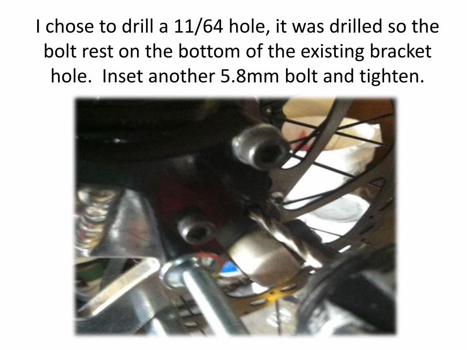
I chose to drill a 11/64 hole, it was drilled so the bolt rest on the bottom of the existing bracket hole. Inset another 5.8mm bolt and tighten.
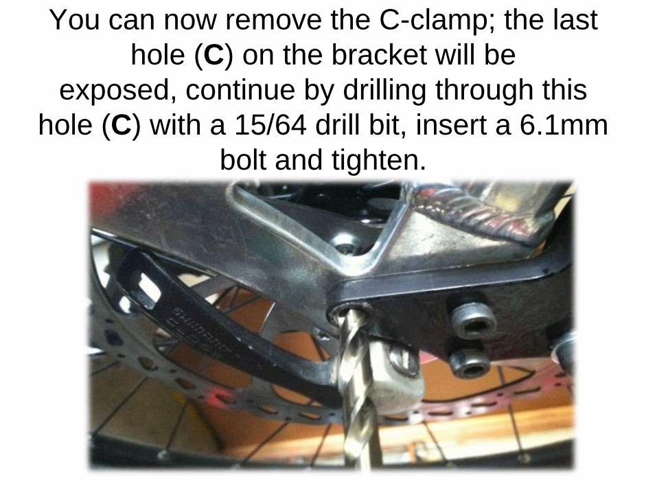
You can now remove the C-clamp; the last
hole (C) on the bracket will be
exposed, continue by drilling through this
hole (C) with a 15/64 drill bit, insert a 6.1mm
bolt and tighten.
Your new braking system
should now be working, check
your wheel to make sure there
is no resistance, if there is little
resistance all you need to do is
adjust your caliper using the
same process described above
on slides No 11 & 12.
The last part of this process will cover the installation of your forward
pressure support arm, you will have lots of pressure on the front of the
universal bracket and I felt a support was needed. I’m no engineer but I feel
that not having this support arm will run the chance of braking or having
something give due to the amount of pressure the brakes will generate.
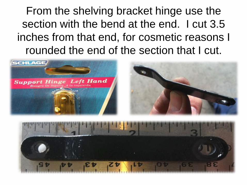
From the shelving bracket hinge use the
section with the bend at the end. I cut 3.5
inches from that end, for cosmetic reasons I
rounded the end of the section that I cut.
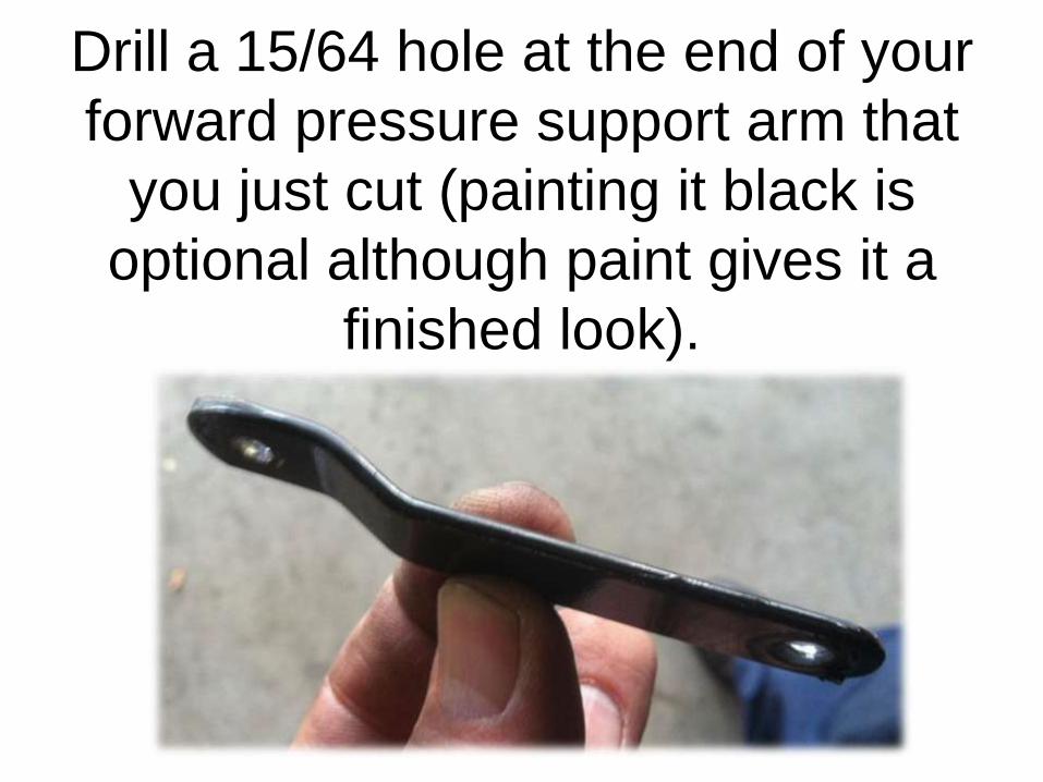
Drill a 15/64 hole at the end of your
forward pressure support arm that
you just cut (painting it black is
optional although paint gives it a
finished look).
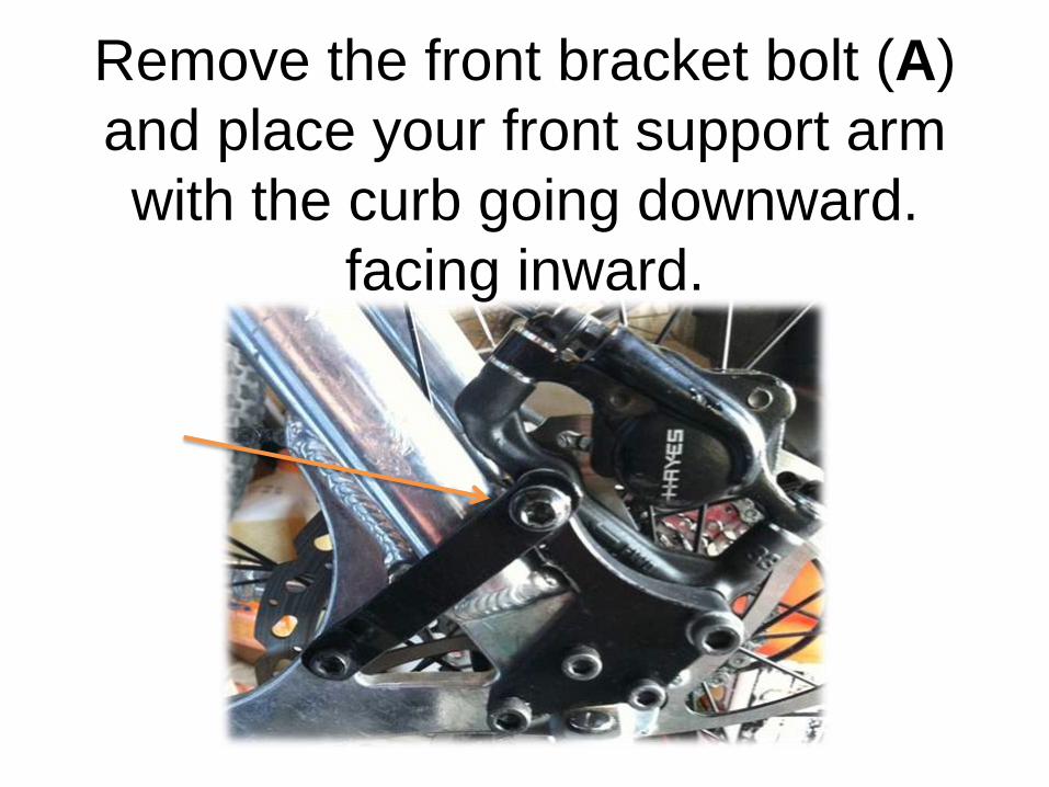
Remove the front bracket bolt (A)
and place your front support arm
with the curb going downward.
facing inward.
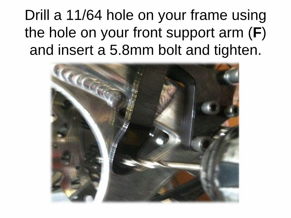
Drill a 11/64 hole on your frame using
the hole on your front support arm (F)
and insert a 5.8mm bolt and tighten.
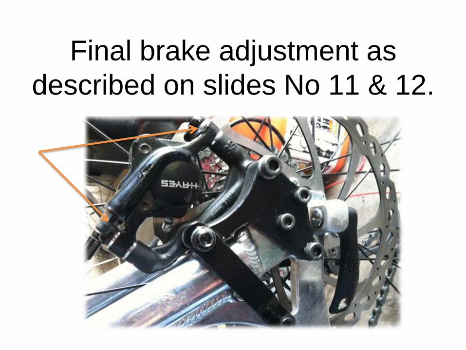
Final brake adjustment as
described on slides No 11 & 12.
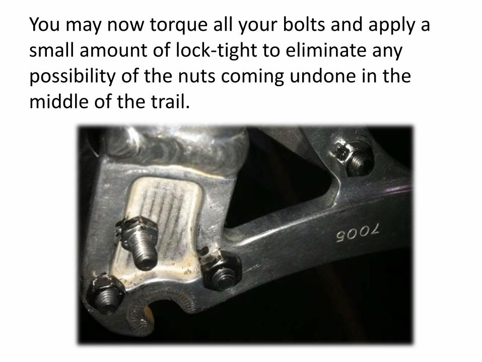
You may now torque all your bolts and apply a small amount of lock-tight to eliminate any possibility of the nuts coming undone in the middle of the trail.
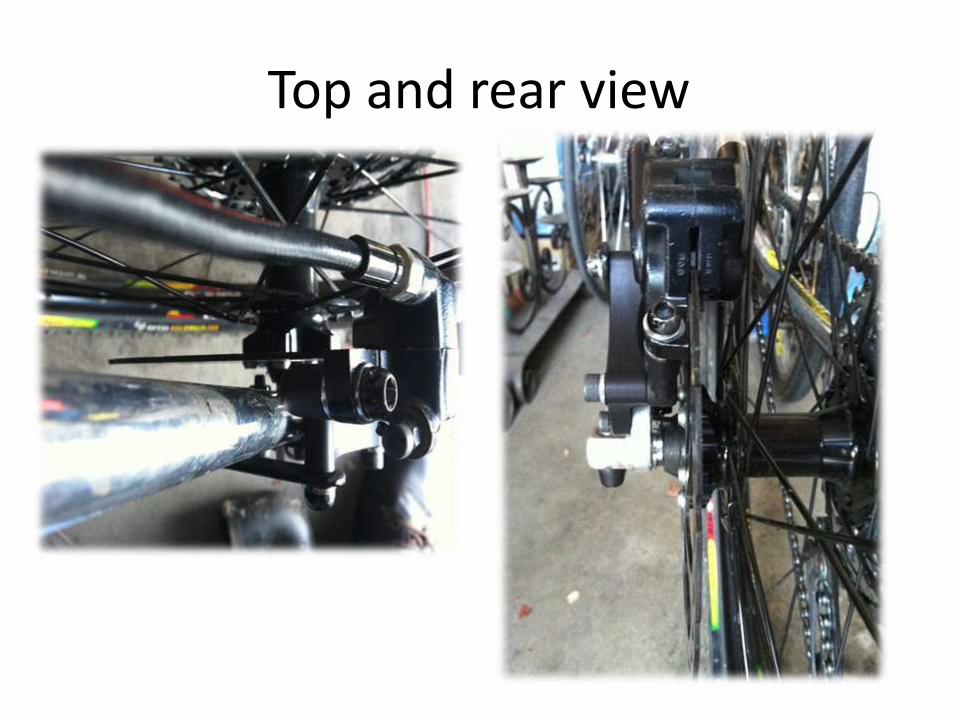
Top and rear view
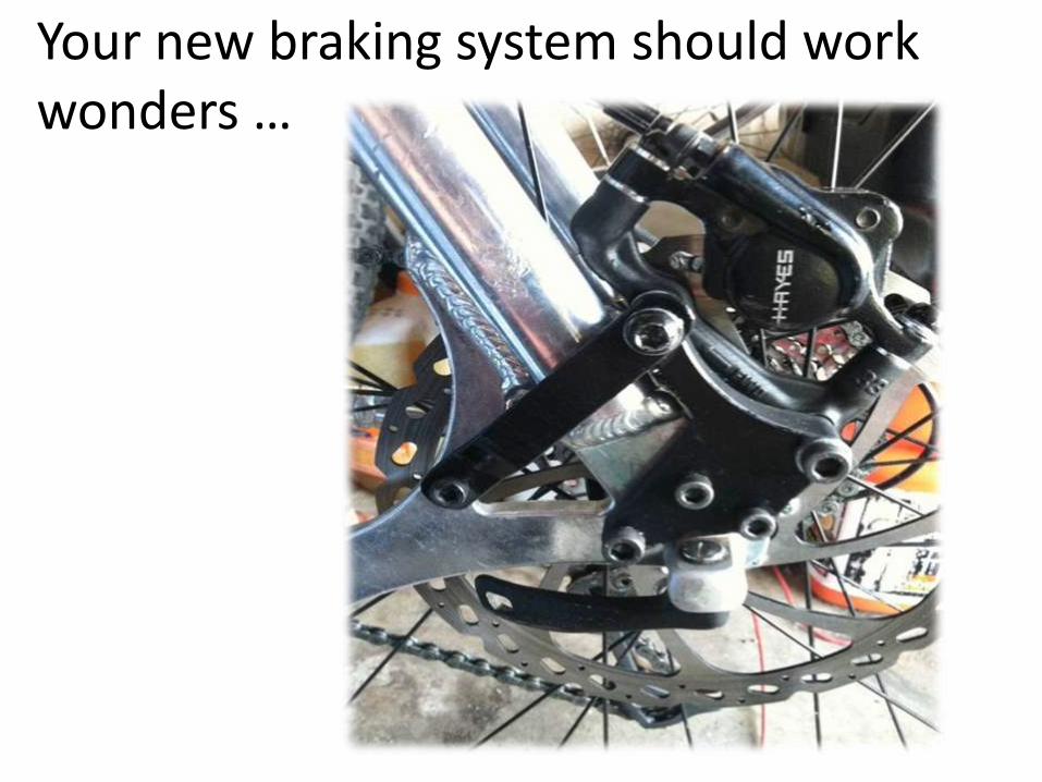
Your new braking system should work wonders …