gt protection type test
TRANSCRIPT
#1 Generator Protection System I Commissioning Report (10CHA01)
2X300MW TTHERMAL POWER PLANT
YAMUNA NAGAR HARYANA-INDIA
#1 Genrator Protection System I (10CHA01)
Commissioning Report
Commissioning:
Check:
Date:
- 1 -
#1 Generator Protection System I Commissioning Report (10CHA01)
Section I: Authorized Illumination
I. ObjectiveThis report is specially set for the designed of 2X300MW TTHERMAL POWER PLANT YAMUNA
NAGAR HARYANA-INDIA #1 Generator Protection System I(10CHA01) as a verification plan for
inspection of system and performance of device.
II. Foundation & Sampling1. 《Technical Specifications for Relaying Protection and Safe Automatic Devices》Issued by Ministry
2. 《Generad specification for control and protection panel(cabinet、desk)of secondary circuit of power
system》JB/T 5777.3 – 2002
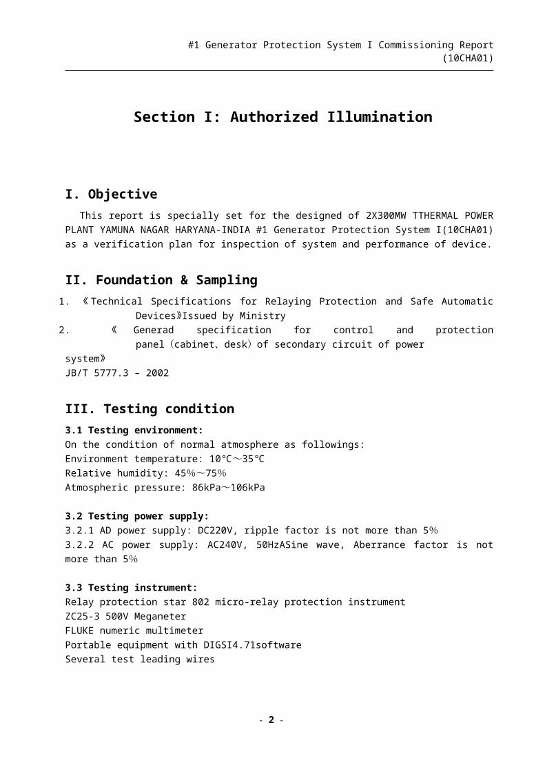
III. Testing condition3.1 Testing environment:
On the condition of normal atmosphere as followings:
Environment temperature: 10℃~35℃
Relative humidity: 45%~75%Atmospheric pressure: 86kPa~106kPa
3.2 Testing power supply:
3.2.1 AD power supply: DC220V, ripple factor is not more than 5%3.2.2 AC power supply: AC240V, 50HzASine wave, Aberrance factor is not more than 5%
3.3 Testing instrument:
Relay protection star 802 micro-relay protection instrument
ZC25-3 500V Meganeter
FLUKE numeric multimeter
Portable equipment with DIGSI4.71software
Several test leading wires
IV. Notice proceedings 4.1 Turn off the switch of power supply before plug or pull the module to make the DC power supply off.
Never plug or pull the module with electricity to prevent the component from damage.
4.2 Special measures must be adopted during the module plug or pull to avoid component damages by static
electricity of human body.
4.3 Fix earthing screw firmly to the earth lead before other connections achieved
4.4 High voltage may occur between the circuit and component used for connecting the DC power supply or
- 2 -
#1 Generator Protection System I Commissioning Report (10CHA01)
testing or experiment.
4.5 Risky high voltage may occur on the device even if the DC circuit switch off. (The energy storage
capacitor discharge)
4.6 The testing capacity cannot exceed the limit number specified in the technical datasheet for every device.
V. Testing Contents5.1 Machinery appearance and configuration inspection
5.2 Equipment and connections
5.3 Insulation property
5.4 Electric property
Section II: Test data and results
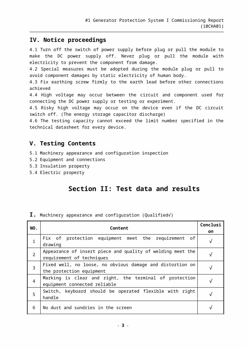
I. Machinery appearance and configuration (Qualified√)
NO. Content Conclusion
1 Fix of protection equipment meet the requirement of drawing √2 Appearance of insert piece and quality of welding meet the requirement of techniques √3 Fixed well, no loose, no obvious damage and distortion on the protection equipment √4 Marking is clear and right, the terminal of protection equipment connected reliable √5 Switch, keyboard should be operated flexible with right handle √6 No dust and sundries in the screen √7 Easy to move the door of screen and open the lock √8 No lacquer drop and knock and fish tail inside and outside of the screen √9 All kinds of markings and signs are right and clear √
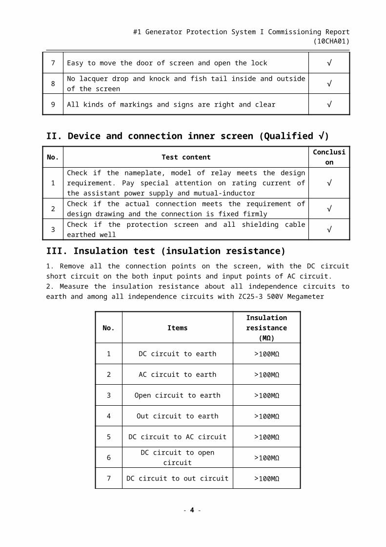
II. Device and connection inner screen (Qualified √)No. Test content Conclusion
1Check if the nameplate, model of relay meets the design requirement. Pay special
attention on rating current of the assistant power supply and mutual-inductor√
2Check if the actual connection meets the requirement of design drawing and the
connection is fixed firmly√
3 Check if the protection screen and all shielding cable earthed well √
III. Insulation test (insulation resistance)1. Remove all the connection points on the screen, with the DC circuit short circuit on the both input points
and input points of AC circuit.
2. Measure the insulation resistance about all independence circuits to earth and among all independence
circuits with ZC25-3 500V Megameter
No. ItemsInsulation resistance
(MΩ)
- 3 -
#1 Generator Protection System I Commissioning Report (10CHA01)
1 DC circuit to earth >100MΩ
2 AC circuit to earth >100MΩ
3 Open circuit to earth >100MΩ
4 Out circuit to earth >100MΩ
5 DC circuit to AC circuit >100MΩ
6 DC circuit to open circuit >100MΩ
7 DC circuit to out circuit >100MΩ
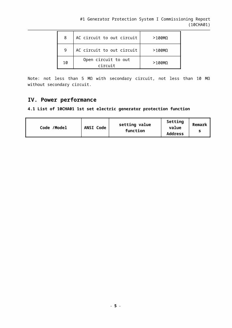
8 AC circuit to out circuit >100MΩ
9 AC circuit to out circuit >100MΩ
10 Open circuit to out circuit >100MΩ
Note: not less than 5 MΩ with secondary circuit, not less than 10 MΩ without secondary circuit.
IV. Power performance 4.1 List of 10CHA01 1st set electric generator protection function
Code /Model ANSI Code setting value functionSetting value
AddressRemarks
- 4 -
#1 Generator Protection System I Commissioning Report (10CHA01)
F11
7UM6225-5EB92-0CA0-LOD
87GGenerator differential
protection2001~2063
64G Stator earth protection 6001
21 Impedance protection 3301~3317
59 Over voltage protection 4101~4107
95 Generator interturn fault Pro. 5501
27 undervoltage protection 4001~4006
50VOvercurrent protection(with
undervoltage)1301~1305
81 Frequency protection 4201~4215
46 Neg. overcurrent protection 1701~1707
49 Overload protection 1601~1616
40 Loss of execited 3001~3014
32F Low power protection 3201~3206
32R Reverse Power protection 3101~3105
24 Overexcitation protection 4301~4305
78Generator Pole Slipping
Protection3501~3512
50/27 Inadvertent energizing Pro. 7101~7105
F12
7UM6115-5EB90-0AA0-LOD32R Reverse Power protection 3101~3105
4.1.1 Information about protection equipment of electric generator (7UM6225-5EB92-0CA0-LOD)
Manufacturer SIEMENS Model 7UM6225-5EB92-0CA0-LOD
Serial No.BF061005154
2Software version V 4.6
Mounting position 10CHA01-F11 Purpose Generator protection
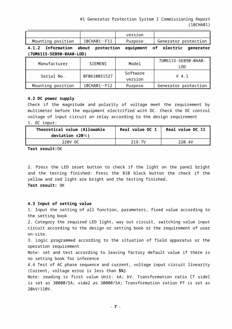
4.1.2 Information about protection equipment of electric generator (7UM6115-5EB90-0AA0-LOD)
Manufacturer SIEMENS Model 7UM6115-5EB90-0AA0-LOD
Serial No.BF061005152
7Software version V 4.1
Mounting position 10CHA01-F12 Purpose Generator protection
4.2 DC power supply
Check if the magnitude and polarity of voltage meet the requirement by multimeter before the equipment
electrified with DC. Check the DC control voltage of input circuit on relay according to the design requirement
1. DC input:
- 5 -

#1 Generator Protection System I Commissioning Report (10CHA01)
Theoretical value (Allowable deviation ±20%) Real value DC I Real value DC II
220V DC 219.7V 220.4V
Test result:OK
2. Press the LED reset button to check if the light on the panel bright and the testing finished: Press the B10
black button the check if the yellow and red light are bright and the testing finished.
Test result: OK
4.3 Input of setting value
1. Input the setting of all function, parameters, fixed value according to the setting book
2. Category the required LED light, way out circuit, switching value input circuit according to the design or
setting book or the requirement of user on-site.
3. Logic programmed according to the situation of field apparatus or the operation requirement
Note: set and test according to leaving factory default value if there is no setting book for inference
4.4 Test of AC phase sequence and current, voltage input circuit linearity (Current, voltage error is less than
5%)
Note: reading is first value Unit: kA; kV. Transformation ratio CT side1 is set as 30000/5A; side2 as
30000/5A; Transformation ration PT is set as 20kV/110V.
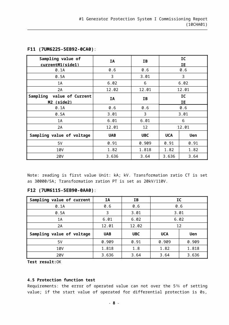
F11 (7UM6225-5EB92-0CA0):
Sampling value of currentM1(side1) IA IBIC
IE0.1A 0.6 0.6 0.6
0.5A 3 3.01 3
1A 6.02 6 6.02
2A 12.02 12.01 12.01
Sampling value of Current M2
(side2)IA IB
IC
IE0.1A 0.6 0.6 0.6
0.5A 3.01 3 3.01
1A 6.01 6.01 6
2A 12.01 12 12.01
Sampling value of voltage UAB UBC UCA Uen
5V 0.91 0.909 0.91 0.91
10V 1.82 1.818 1.82 1.82
20V 3.636 3.64 3.636 3.64
Note: reading is first value Unit: kA; kV. Transformation ratio CT is set as 30000/5A; Transformation ration
PT is set as 20kV/110V.
F12 (7UM6115-5EB90-0AA0):
- 6 -
#1 Generator Protection System I Commissioning Report (10CHA01)
Sampling value of current IA IB IC
0.1A 0.6 0.6 0.6
0.5A 3 3.01 3.01
1A 6.01 6.02 6.02
2A 12.01 12.02 12
Sampling value of voltage UAB UBC UCA Uen
5V 0.909 0.91 0.909 0.909
10V 1.818 1.8 1.82 1.818
20V 3.636 3.64 3.64 3.636
Test result:OK
4.5 Protection function test
Requirements: the error of operated value can not over the 5% of setting value; if the start value of operated for differential protection is 0s, the value of 1.5 times is about 35ms and the allowable error of additional relay
time is 1% of setting value for time.
4.5.1 F11 (7UM6225-5EB92-0CA0):1. Test data of differential protection (87G):
Title
Items
Name:GenratorProtectionAddress:11Model: 7UM6225-5EB92-0CA0
Serial No.:
BF0610051542
Version of software:
V4.6
Voltage ratio:
20KV/110V
Power parameter
Side1CT no-load
voltage ratio:
12000A/5A
Side 2 CT no-load
voltage ratio:
12000A/5A
Capacity: 353MVA
Differe
ntial
protect
ion
87G
Setting value Test result
pickupI=0.3I/In0
T=0
SIDE1 A SIDE1 B SIDE1 C SIDE2 A SIDE2 B SIDE2 C
1.266A 1.264A 1.265A 1.266A 1.265A 1.263A
Diff.
I=5 I/In0
T=0SDIE1 A SIDE1 B SIDE1 C SIDE2 A SIDE2 B SIDE2 C
2.115A 2.114A 2.116A 2.117A 2.115A 2.113A
Slope 1
S1=0.25
Basic point 0SIDE1 A & SIDE2 A SIDE1 B & SIDE2 B SIDE1 C & SIDE2 C
5.33A/3.198A 5.33A/3.196A 5.33A/3.194A
Slope 2
S2=0.5
Basic point
2.5 I/In0
SIDE1 A & S2 A SIDE1 B & SIDE2 B SIDE1 C & SIDE2 C
16.453A/9.01A 16.453A/9A 16.453A/8.98A
2. Test data of stator earth protecion (59N/67GN) :
Protection Setting value Operated value Setting time (s) Operated time (s)
- 7 -
#1 Generator Protection System I Commissioning Report (10CHA01)
59N> 10V 10.01V 0.3 0.301
3. Test data of stator earth protection with 3rd Harmonics(27/59TN) :
Protection Setting value Operated value Setting time (s) Operated time (s)
59TN> 2V 2.01V 0.5 0.501
4. Test data of low resistance protection (21):
Protection Setting value Operated value Setting time (s) Operated time (s)
Z1 0.11 Ohm 0.11 Ohm 0.3 0.3
Z1B 0.19 Ohm 0.19 Ohm 0.3 0.3
Z2 0.19 Ohm 0.19 Ohm 3.5 3.501
5. Test data of over-voltage protection (59):
Protection Setting value Operated value Setting time (s) Operated time (s)
U> 120V 119.85V 3 3.02
U>> 130V 129.73V 0.5 0.501
6. Test data of interturn protection on generator:
Protection Setting value Operated value Setting time (s) Operated time (s)
95 2.2V 2.2V 0.5 0.501
7. Test date of under-voltage protection (27):
Protection Setting value Operated value Setting time (s) Operated time (s)
U< 75V 74.99V 3 3.01
U<< 65V 64.95V 0.5 0.502
8. Test data of back up over current protection (51) (undervoltage holding):
Protection Setting value Operated value Setting time (s) Operated time (s)
I> 7A 7.01A 3.5 3.499
U< 80V 79.9V 8 8.01
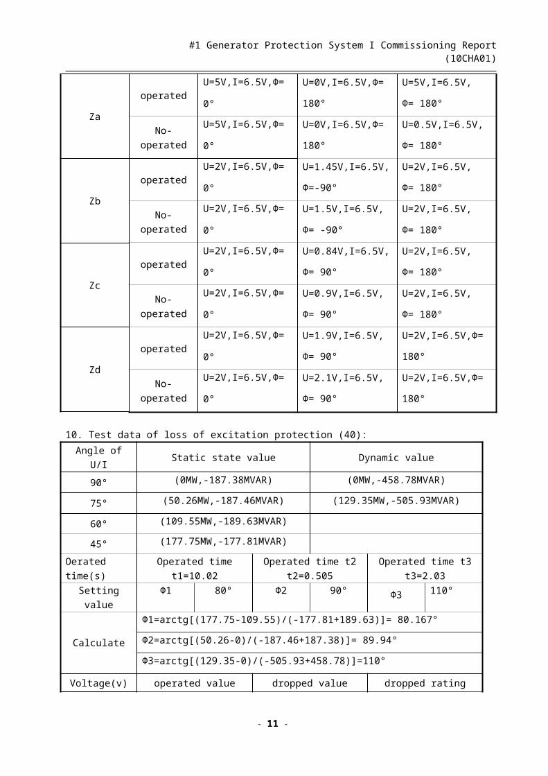
9. Test data of generator pole slipping protection (78):
Borderline of
impedanceOperated state First list Second list Third list
- 8 -

#1 Generator Protection System I Commissioning Report (10CHA01)
Za
operated
U=5V,I=6.5V,Φ=
0°
U=0V,I=6.5V,Φ=
180°
U=5V,I=6.5V,
Φ= 180°
No-operated
U=5V,I=6.5V,Φ=
0°
U=0V,I=6.5V,Φ=
180°
U=0.5V,I=6.5V,
Φ= 180°
Zb
operated
U=2V,I=6.5V,Φ=
0°
U=1.45V,I=6.5V,
Φ=-90°
U=2V,I=6.5V,
Φ= 180°
No-operated
U=2V,I=6.5V,Φ=
0°
U=1.5V,I=6.5V,
Φ= -90°
U=2V,I=6.5V,
Φ= 180°
Zc
operated
U=2V,I=6.5V,Φ=
0°
U=0.84V,I=6.5V,
Φ= 90°
U=2V,I=6.5V,
Φ= 180°
No-operated
U=2V,I=6.5V,Φ=
0°
U=0.9V,I=6.5V,
Φ= 90°
U=2V,I=6.5V,
Φ= 180°
Zd
operated
U=2V,I=6.5V,Φ=
0°
U=1.9V,I=6.5V,
Φ= 90°
U=2V,I=6.5V,Φ=
180°
No-operated
U=2V,I=6.5V,Φ=
0°
U=2.1V,I=6.5V,
Φ= 90°
U=2V,I=6.5V,Φ=
180°
10. Test data of loss of excitation protection (40):
Angle of U/I Static state value Dynamic value
90° (0MW,-187.38MVAR) (0MW,-458.78MVAR)
75° (50.26MW,-187.46MVAR) (129.35MW,-505.93MVAR)
60° (109.55MW,-189.63MVAR)
45° (177.75MW,-177.81MVAR)
Oerated time(s) Operated time t1=10.02Operated time t2
t2=0.505
Operated time t3
t3=2.03
Setting value Φ1 80° Φ2 90° Φ3 110°
Calculate
Φ1=arctg[(177.75-109.55)/(-177.81+189.63)]= 80.167°
Φ2=arctg[(50.26-0)/(-187.46+187.38)]= 89.94°
Φ3=arctg[(129.35-0)/(-505.93+458.78)]=110°
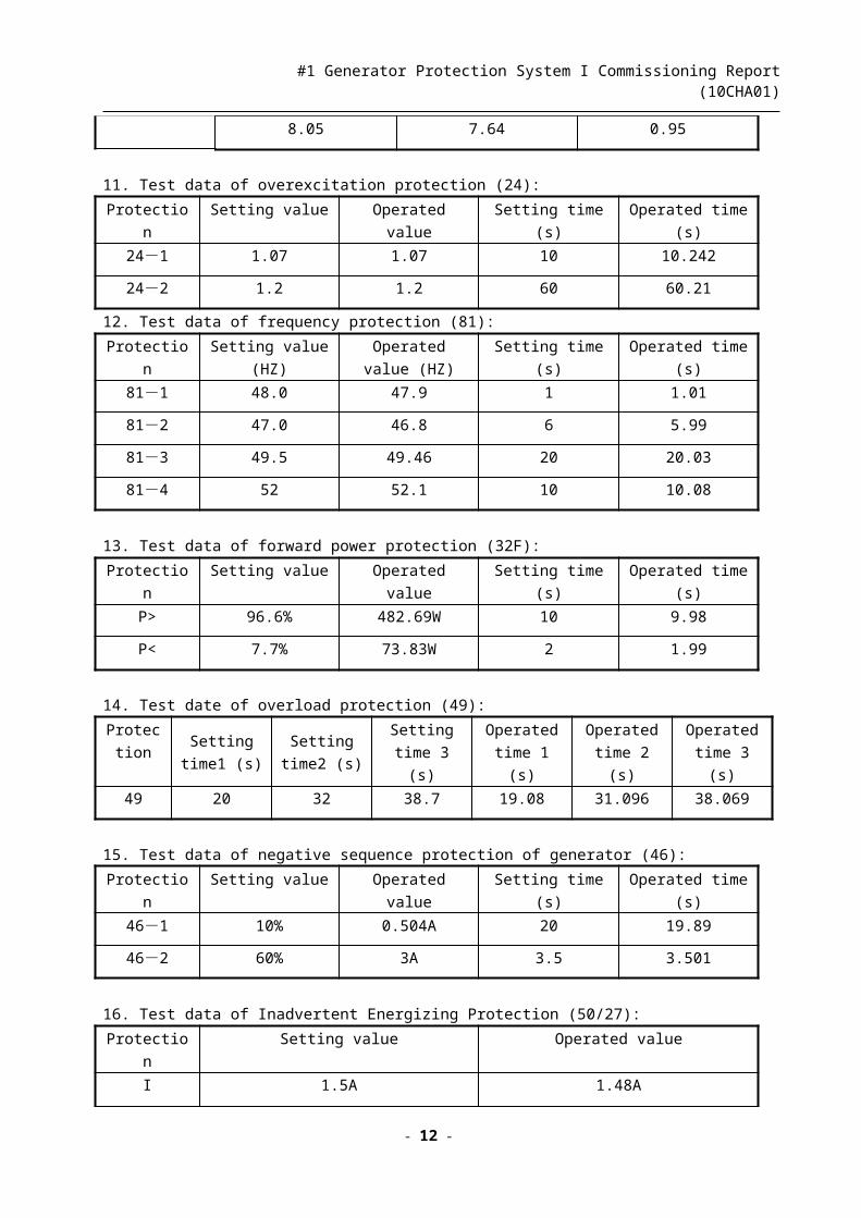
Voltage(v)operated value dropped value dropped rating
8.05 7.64 0.95
- 9 -

#1 Generator Protection System I Commissioning Report (10CHA01)
11. Test data of overexcitation protection (24):
Protection Setting value Operated value Setting time (s) Operated time (s)
24-1 1.07 1.07 10 10.242
24-2 1.2 1.2 60 60.21
12. Test data of frequency protection (81):
Protection Setting value (HZ) Operated value
(HZ)
Setting time (s) Operated time (s)
81-1 48.0 47.9 1 1.01
81-2 47.0 46.8 6 5.99
81-3 49.5 49.46 20 20.03
81-4 52 52.1 10 10.08
13. Test data of forward power protection (32F):
Protection Setting value Operated value Setting time (s) Operated time (s)
P> 96.6% 482.69W 10 9.98
P< 7.7% 73.83W 2 1.99
14. Test date of overload protection (49):
Protectio
n
Setting
time1 (s)
Setting
time2 (s)
Setting
time 3 (s)
Operated
time 1 (s)
Operated
time 2 (s)
Operated
time 3 (s)
49 20 32 38.7 19.08 31.096 38.069
15. Test data of negative sequence protection of generator (46):
Protection Setting value Operated value Setting time (s) Operated time (s)
46-1 10% 0.504A 20 19.89
46-2 60% 3A 3.5 3.501
16. Test data of Inadvertent Energizing Protection (50/27):
Protection Setting value Operated value
I 1.5A 1.48A
V1 55V 54.97V
T 0.5S 0.498S
4.5.2 F12 (7UM6115-5EB90-0AA0):
1. Test data of reverse power protection (32R):
Protection Setting value Operated value Setting time (s) Operated time (s)
- 10 -
#1 Generator Protection System I Commissioning Report (10CHA01)
P> -3.62% -11.49W 5 5.08
Test result: OK
4.6 Function test (Qualified “√”)
4.6.1 F11 (7UM6225-5EB92-0CA0) Name Test method Device F11 Result
Loss-water of generator Short circuit between X130-1and X130-9 BI1 √Tripping operation on
thermodynamic protectionShort circuit between X130-1 and X130-10 BI2 √
Main stop valve shut off Short circuit between X130-1 and X130-11 BI3 √Field breaker close Short circuit between X130-1 and X130-12 BI4 √
Main convertor 220kV side
circuit breaker closeShort circuit between X130-1 and X130-13 BI5 √
High temperature on the
Stator windingShort circuit between X130-1 and X130-14 BI6 √
High-high temperature on
the stator windingShort circuit between X130-1 and X130-15 BI7 √
Differential generator-
transformer setShort circuit between X130-21 and X130-
29BI9 √
Unit transformer#1 differential protection
Short circuit between X130-21 and X130-30
BI10 √
Unit transformer#2 differential protection
Short circuit between X130-21 and X130-31
BI11 √
Unit transformer#1 zero-sequence differential
protection on low voltage
Short circuit between X130-21 and X130-32
BI12 √
Unit transformer#1 instantaneous current
protection on the high
voltage side
Short circuit between X130-21 and X130-33
BI13 √
unit transformer#2 instantaneous current
protection on the high
voltage side
Short circuit between X130-21 and X130-34
BI14 √
Main transformer on the
side of high voltage backup
earth fault protection
Short circuit between X130-21 and X130-35
BI15 √
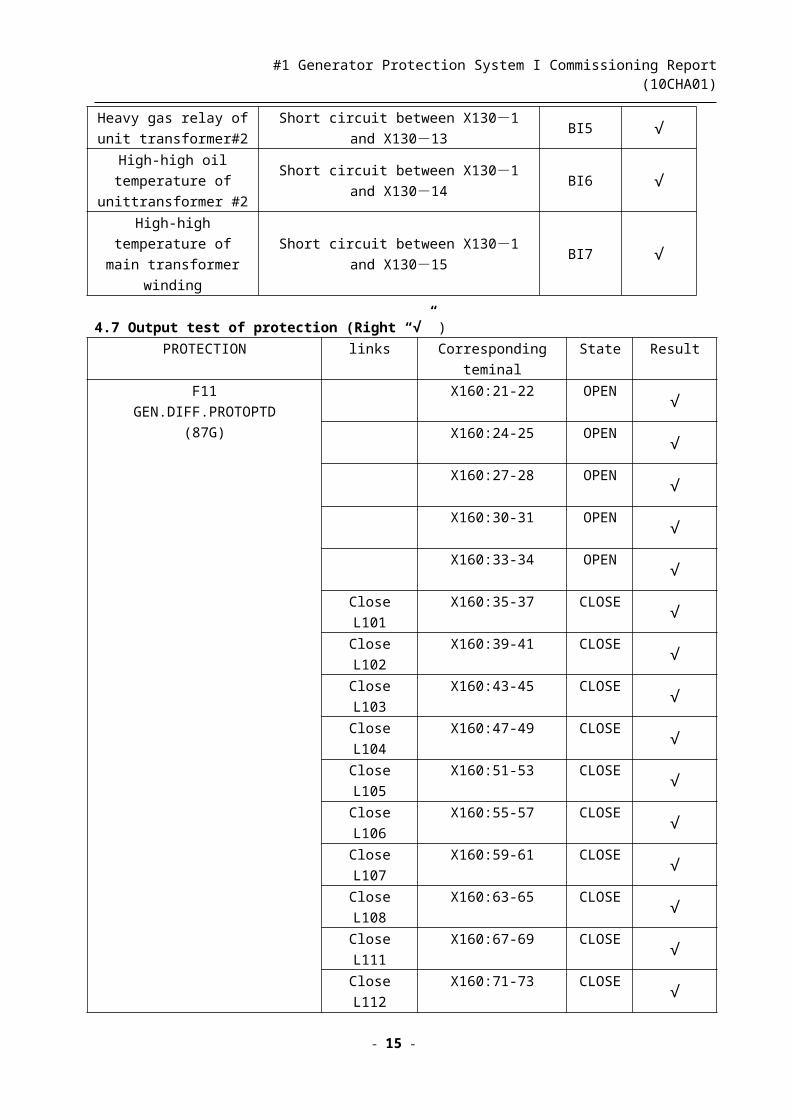
4.6.2 F12 (7UM6115-5EB90-0AA0) Name Test method Device F11 Result
Main heavy gas relay Short circuit between X130-1and X130-9 BI1 √
- 11 -
#1 Generator Protection System I Commissioning Report (10CHA01)
Main transformer
on load tap changing oil
pressure releaseShort circuit between X130-1 and X130-10 BI2 √
Heavy gas relay of plant
unit transformer #1Short circuit between X130-1 and X130-11 BI3 √
High-high oil temperature
of unit transformer #1Short circuit between X130-1 and X130-12 BI4 √
Heavy gas relay of unit
transformer#2Short circuit between X130-1 and X130-13 BI5 √
High-high oil temperature
of unittransformer #2Short circuit between X130-1 and X130-14 BI6 √
High-high temperature of
main transformer windingShort circuit between X130-1 and X130-15 BI7 √
4.7 Output test of protection (Right “√” )
PROTECTION links Corresponding teminal State Result
F11
GEN.DIFF.PROTOPTD
(87G)
X160:21-22 OPEN √
X160:24-25 OPEN √
X160:27-28 OPEN √
X160:30-31 OPEN √
X160:33-34 OPEN √
Close L101 X160:35-37 CLOSE √Close L102 X160:39-41 CLOSE √Close L103 X160:43-45 CLOSE √Close L104 X160:47-49 CLOSE √Close L105 X160:51-53 CLOSE √Close L106 X160:55-57 CLOSE √Close L107 X160:59-61 CLOSE √Close L108 X160:63-65 CLOSE √Close L111 X160:67-69 CLOSE √Close L112 X160:71-73 CLOSE √Close L113 X160:75-77 CLOSE √
X170:15-16 CLOSE √
X171:7-8 CLOSE √
X172:7-8 CLOSE √
X173:3-4 CLOSE √
X100:3-9 CLOSE √
F11
GEN.STATOR EARTH FAULT
X160:21-22 OPEN √
X160:24-25 OPEN √
- 12 -

#1 Generator Protection System I Commissioning Report (10CHA01)
PROT.95% (64G1)
X160:27-28 OPEN √
X160:30-31 OPEN √
X160:33-34 OPEN √
Close L101 X160:35-37 CLOSE √Close L102 X160:39-41 CLOSE √Close L103 X160:43-45 CLOSE √Close L104 X160:47-49 CLOSE √Close L105 X160:51-53 CLOSE √Close L106 X160:55-57 CLOSE √Close L107 X160:59-61 CLOSE √Close L108 X160:63-65 CLOSE √Close L111 X160:67-69 CLOSE √Close L112 X160:71-73 CLOSE √Close L113 X160:75-77 CLOSE √
X170:15-16 CLOSE √
X171:7-8 CLOSE √
X172:7-8 CLOSE √
X173:3-4 CLOSE √
X100:3-9 CLOSE √
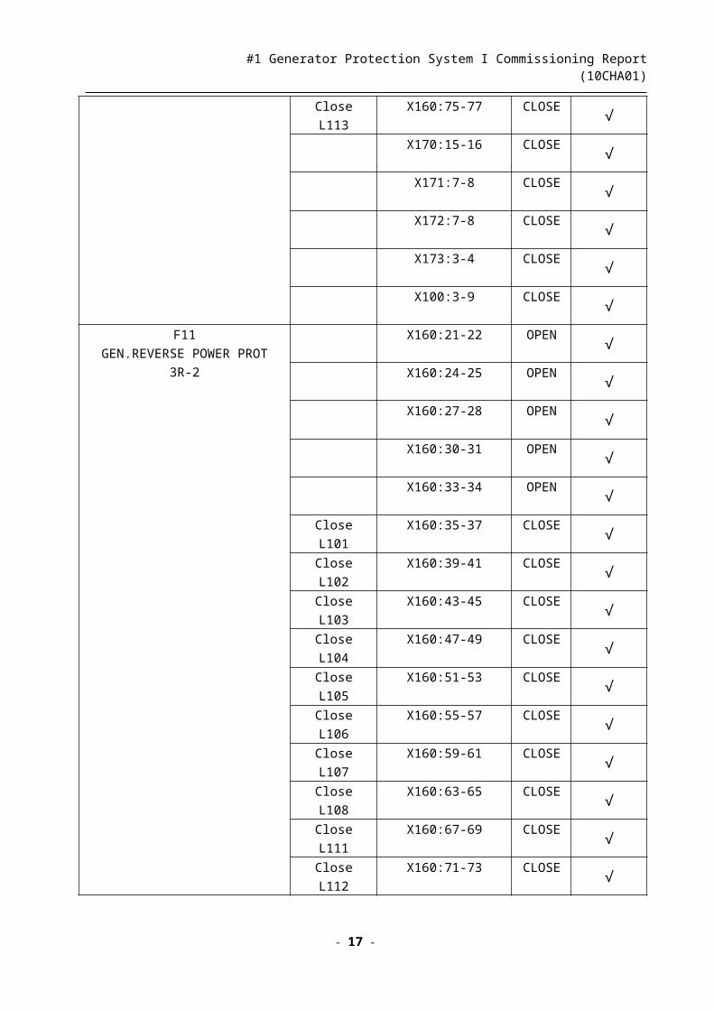
F11
GEN.REVERSE POWER PROT
3R-2
X160:21-22 OPEN √
X160:24-25 OPEN √
X160:27-28 OPEN √
X160:30-31 OPEN √
X160:33-34 OPEN √
Close L101 X160:35-37 CLOSE √Close L102 X160:39-41 CLOSE √Close L103 X160:43-45 CLOSE √Close L104 X160:47-49 CLOSE √Close L105 X160:51-53 CLOSE √Close L106 X160:55-57 CLOSE √Close L107 X160:59-61 CLOSE √Close L108 X160:63-65 CLOSE √Close L111 X160:67-69 CLOSE √
Close L112 X160:71-73 CLOSE √Close L113 X160:75-77 CLOSE √
X170:15-16 CLOSE √
X171:7-8 CLOSE √
- 13 -

#1 Generator Protection System I Commissioning Report (10CHA01)
X172:7-8 CLOSE √
X173:3-4 CLOSE √
X100:3-9 CLOSE √
F11
GEN.LOW FORWARD POWER
PROT .32F
X160:21-22 OPEN √
X160:24-25 OPEN √
X160:27-28 OPEN √
X160:30-31 OPEN √
X160:33-34 OPEN √
Close L101 X160:35-37 CLOSE √Close L102 X160:39-41 CLOSE √Close L103 X160:43-45 CLOSE √Close L104 X160:47-49 CLOSE √Close L105 X160:51-53 CLOSE √Close L106 X160:55-57 CLOSE √Close L107 X160:59-61 CLOSE √Close L108 X160:63-65 CLOSE √Close L111 X160:67-69 CLOSE √Close L112 X160:71-73 CLOSE √Close L113 X160:75-77 CLOSE √
X170:15-16 CLOSE √
X171:7-8 CLOSE √
X172:7-8 CLOSE √
X173:3-4 CLOSE √
X100:3-9 CLOSE √
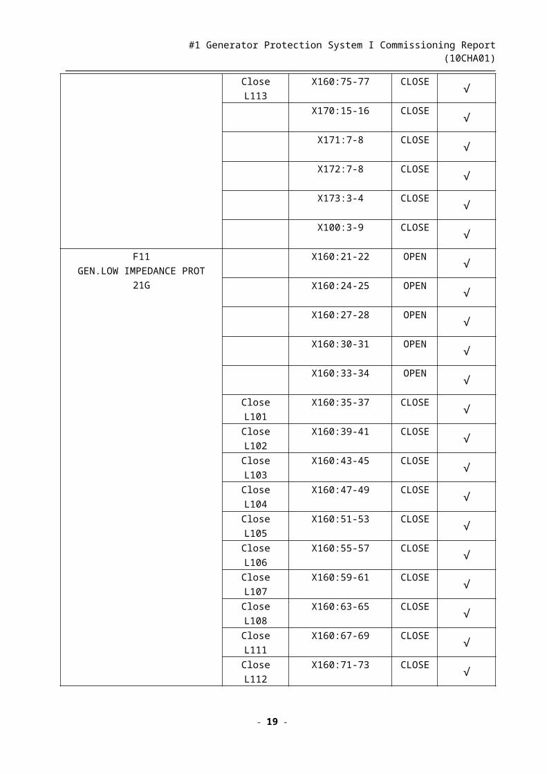
F11
GEN.LOW IMPEDANCE PROT
21G
X160:21-22 OPEN √
X160:24-25 OPEN √
X160:27-28 OPEN √
X160:30-31 OPEN √
X160:33-34 OPEN √
Close L101 X160:35-37 CLOSE √Close L102 X160:39-41 CLOSE √Close L103 X160:43-45 CLOSE √Close L104 X160:47-49 CLOSE √Close L105 X160:51-53 CLOSE √Close L106 X160:55-57 CLOSE √Close L107 X160:59-61 CLOSE √Close L108 X160:63-65 CLOSE √
- 14 -
#1 Generator Protection System I Commissioning Report (10CHA01)
Close L111 X160:67-69 CLOSE √Close L112 X160:71-73 CLOSE √Close L113 X160:75-77 CLOSE √
X170:15-16 CLOSE √
X171:7-8 CLOSE √
X172:7-8 CLOSE √
X173:3-4 CLOSE √
X100:3-9 CLOSE √
F11
GEN. OVEROVOLTAGE PROT
59G2
X160:21-22 OPEN √
X160:24-25 OPEN √
X160:27-28 OPEN √
X160:30-31 OPEN √
X160:33-34 OPEN √
Close L101 X160:35-37 CLOSE √Close L102 X160:39-41 CLOSE √Close L103 X160:43-45 CLOSE √Close L104 X160:47-49 CLOSE √Close L105 X160:51-53 CLOSE √Close L106 X160:55-57 CLOSE √Close L107 X160:59-61 CLOSE √Close L108 X160:63-65 CLOSE √Close L111 X160:67-69 CLOSE √Close L112 X160:71-73 CLOSE √Close L113 X160:75-77 CLOSE √
X170:15-16 CLOSE √
X171:7-8 CLOSE √
X172:7-8 CLOSE √
X173:3-4 CLOSE √
X100:3-9 CLOSE √
F11
GEN. INTERTURN PROT
95
X160:21-22 OPEN √
X160:24-25 OPEN √
X160:27-28 OPEN √
X160:30-31 OPEN √
X160:33-34 OPEN √
Close L101 X160:35-37 CLOSE √Close L102 X160:39-41 CLOSE √Close L103 X160:43-45 CLOSE √
- 15 -

#1 Generator Protection System I Commissioning Report (10CHA01)
Close L104 X160:47-49 CLOSE √Close L105 X160:51-53 CLOSE √Close L106 X160:55-57 CLOSE √Close L107 X160:59-61 CLOSE √Close L108 X160:63-65 CLOSE √Close L111 X160:67-69 CLOSE √Close L112 X160:71-73 CLOSE √Close L113 X160:75-77 CLOSE √
X170:15-16 CLOSE √
X171:7-8 CLOSE √
X172:7-8 CLOSE √
X173:3-4 CLOSE √
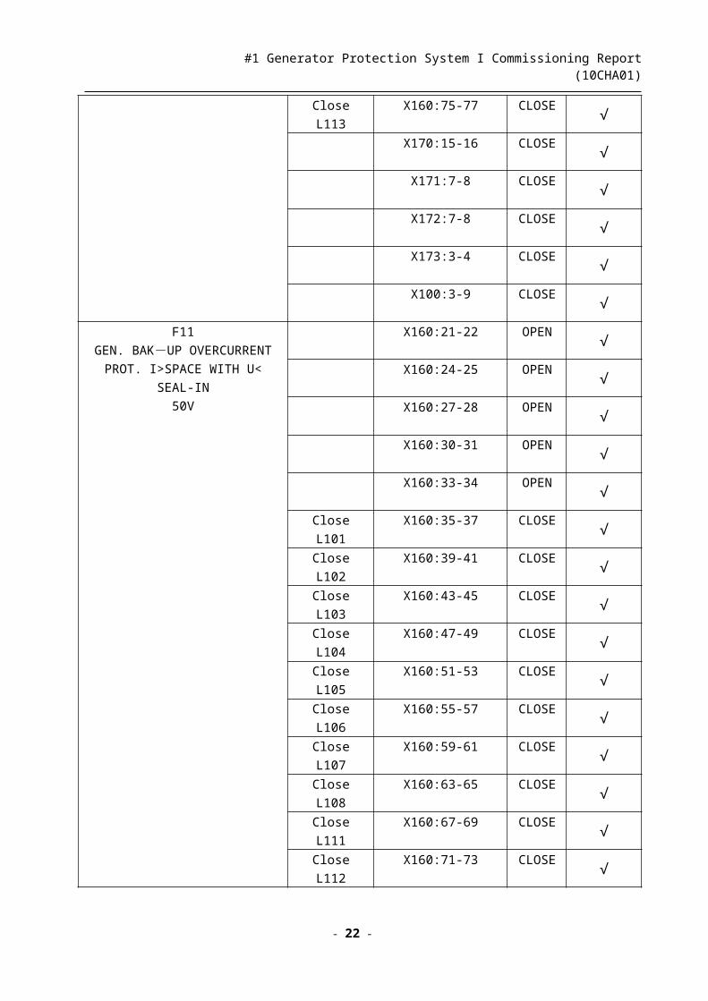
X100:3-9 CLOSE √
F11
GEN. BAK-UP OVERCURRENT PROT. I>SPACE WITH U< SEAL-IN
50V
X160:21-22 OPEN √
X160:24-25 OPEN √
X160:27-28 OPEN √
X160:30-31 OPEN √
X160:33-34 OPEN √
Close L101 X160:35-37 CLOSE √Close L102 X160:39-41 CLOSE √Close L103 X160:43-45 CLOSE √Close L104 X160:47-49 CLOSE √Close L105 X160:51-53 CLOSE √Close L106 X160:55-57 CLOSE √Close L107 X160:59-61 CLOSE √Close L108 X160:63-65 CLOSE √Close L111 X160:67-69 CLOSE √Close L112 X160:71-73 CLOSE √Close L113 X160:75-77 CLOSE √
X170:15-16 CLOSE √
X171:7-8 CLOSE √
X172:7-8 CLOSE √
X173:3-4 CLOSE √
X100:3-9 CLOSE √
F11
GEN. UNBLANCED LOAD PROT
I2>>TRIP
X160:21-22 OPEN √
X160:24-25 OPEN √
X160:27-28 OPEN √
- 16 -
#1 Generator Protection System I Commissioning Report (10CHA01)
46-2
X160:30-31 OPEN √
X160:33-34 OPEN √
Close L101 X160:35-37 CLOSE √Close L102 X160:39-41 CLOSE √Close L103 X160:43-45 CLOSE √Close L104 X160:47-49 CLOSE √Close L105 X160:51-53 CLOSE √Close L106 X160:55-57 CLOSE √Close L107 X160:59-61 CLOSE √Close L108 X160:63-65 CLOSE √Close L111 X160:67-69 CLOSE √Close L112 X160:71-73 CLOSE √Close L113 X160:75-77 CLOSE √
X170:15-16 CLOSE √
X171:7-8 CLOSE √
X172:7-8 CLOSE √
X173:3-4 CLOSE √
X100:3-9 CLOSE √
F11
GEN. UNDER FREQUENCY PROT.
F<47HZ
81U-3
Close L111 X160:67-69 CLOSE √
X170:17-18 CLOSE √
X171:9-10 CLOSE √
X172:9-10 CLOSE √
X173:5-6 CLOSE √
X100:3-9 CLOSE √
F11
GEN. OVEREXCETION PROT.
STAGE-II
OPTD (U/F>>)
24-2
Close L111 X160:67-69 CLOSE √X170:17-18 CLOSE √
X171:9-10 CLOSE √
X172:9-10 CLOSE √
X173:5-6 CLOSE √
X100:3-9 CLOSE √
F11
GEN. OVERLOAD PROT. Θ》TRIP49-2
Close L111 X160:67-69 CLOSE √X170:17-18 CLOSE √
X171:9-10 CLOSE √
X172:9-10 CLOSE √
X173:5-6 CLOSE √
X100:3-9 CLOSE √
- 17 -

#1 Generator Protection System I Commissioning Report (10CHA01)
F11
GEN.LOSS OF EXCITATION
PROT.CHAR2 OPTD (STAT. STAB 2)
40-2
Close L111 X160:67-69 CLOSE √X170:17-18 CLOSE √
X171:9-10 CLOSE √
X172:9-10 CLOSE √
X173:5-6 CLOSE √
X100:3-9 CLOSE √
F11
GEN.UNBLANCED LOAD PROT
I2P> SPACE 46
PROTECTION
Close L111 X160:67-69 CLOSE √X170:17-18 CLOSE √
X171:9-10 CLOSE √
X172:9-10 CLOSE √
X173:5-6 CLOSE √
X100:3-9 CLOSE √
F11 EXTERNAL BINARY INPUT
BI: GT OVERALL DIFFERENTIAL
PROT
BI: UAT #1 DIFFERENTIAL PROT
BI: UAT #1 DIFFERENTIAL PROT
BI: UAT #1 LV RESTRICTED E/F
PROT
BI: UAT #1 HV HIGH SET INST.O/C
PROT
+ LOW SET INVERSE O/C PROT
BI: UAT #1 HV HIGH SET INST.O/C
PROT
+ LOW SET INVERSE O/C PROT
BI: GT HV IDMT STANDBY E/F
PROT
X160:21-22 OPEN √
X160:24-25 OPEN √
X160:27-28 OPEN √
X160:27-28 OPEN √
X160:30-31 OPEN √
X160:33-34 OPEN √
Close L101 X160:35-37 CLOSE √Close L102 X160:39-41 CLOSE √Close L103 X160:43-45 CLOSE √Close L104 X160:47-49 CLOSE √Close L105 X160:51-53 CLOSE √Close L106 X160:55-57 CLOSE √Close L107 X160:59-61 CLOSE √Close L108 X160:63-65 CLOSE √Close L111 X160:67-69 CLOSE √Close L112 X160:71-73 CLOSE √Close L113 X160:75-77 CLOSE √
X170:15-16 CLOSE √
X171:7-8 CLOSE √
X172:7-8 CLOSE √
X173:3-4 CLOSE √
X100:3-9 CLOSE √
F12 EXTERNAL BINARY INPUT X160:21-22 OPEN √
- 18 -
#1 Generator Protection System I Commissioning Report (10CHA01)
TRIP
BI: GT TRANS. BUCHHOLZ
RELAY
BI: GT OLTC OIL SURGE PROT
BI: UAT #1 BUCHHOLZ RELAY
BI: UAT #1 OIL TEMP. HIGH-HIGH
BI: UAT #1 BUCHHOLZ RELAY
BI: UAT #1 OIL TEMP. HIGH-HIGH
X160:24-25 OPEN √
X160:27-28 OPEN √
X160:30-31 OPEN √
X160:33-34 OPEN √
Close L101 X160:35-37 CLOSE √Close L102 X160:39-41 CLOSE √Close L103 X160:43-45 CLOSE √Close L104 X160:47-49 CLOSE √Close L105 X160:51-53 CLOSE √Close L106 X160:55-57 CLOSE √Close L107 X160:59-61 CLOSE √Close L108 X160:63-65 CLOSE √Close L111 X160:67-69 CLOSE √
Close L112 X160:71-73 CLOSE √Close L113 X160:75-77 CLOSE √
X170:15-16 CLOSE √
X171:7-8 CLOSE √
X172:7-8 CLOSE √
X173:3-4 CLOSE √
X100:3-9 CLOSE √
F11
GEN. UNDER FREQUENCY PROT.
81U-2
F<48HZ
X160:21-22 OPEN √
X160:24-25 OPEN √
Close L101 X160:35-37 CLOSE √Close L102 X160:39-41 CLOSE √Close L103 X160:43-45 CLOSE √Close L104 X160:47-49 CLOSE √
X170:19-20 CLOSE √
X171:11-12 CLOSE √
X172:11-12 CLOSE √
X173:7-8 CLOSE √
X100:3-9 CLOSE √
F11
EN. LOSS OF EXCITATION PROT.
40-3
CHAR.3 OPTD (DYA. STAB)
X160:21-22 OPEN √
X160:24-25 OPEN √
Close L101 X160:35-37 CLOSE √Close L102 X160:39-41 CLOSE √Close L103 X160:43-45 CLOSE √Close L104 X160:47-49 CLOSE √
- 19 -

#1 Generator Protection System I Commissioning Report (10CHA01)
X170:19-20 CLOSE √
X171:11-12 CLOSE √
X172:11-12 CLOSE √
X173:7-8 CLOSE √
X100:3-9 CLOSE √
F11
GEN. POLE SLIPPING PROT.
78
CHAR.1 OPTD
X160:21-22 OPEN √
X160:24-25 OPEN √
Close L101 X160:35-37 CLOSE √Close L102 X160:39-41 CLOSE √Close L103 X160:43-45 CLOSE √Close L104 X160:47-49 CLOSE √
X170:19-20 CLOSE √
X171:11-12 CLOSE √
X172:11-12 CLOSE √
X173:7-8 CLOSE √
X100:3-9 CLOSE √
F11
GEN. DEAD MACHINE PROT.
50/27
X160:21-22 OPEN √
X160:24-25 OPEN √
Close L101 X160:35-37 CLOSE √Close L102 X160:39-41 CLOSE √Close L103 X160:43-45 CLOSE √Close L104 X160:47-49 CLOSE √
X170:19-20 CLOSE √
X171:11-12 CLOSE √
X172:11-12 CLOSE √
X173:7-8 CLOSE √
X100:3-9 CLOSE √
F12 EXTERNAL BINARY INPUT
BI: GT WINDING TEMP. HIGH-
HIGH
X160:21-22 OPEN √
X160:24-25 OPEN √
Close L101 X160:35-37 CLOSE √Close L102 X160:39-41 CLOSE √Close L103 X160:43-45 CLOSE √Close L104 X160:47-49 CLOSE √
X170:19-20 CLOSE √
X171:11-12 CLOSE √
X172:11-12 CLOSE √
- 20 -

#1 Generator Protection System I Commissioning Report (10CHA01)
X173:7-8 CLOSE √
X100:3-9 CLOSE √
CIRCUIT BREAKER START FAULT
PROT.
Close L109 X160:79-81 CLOSE √Close L110 X160:83-85 CLOSE √
F11 LOAD REDUCTION PROT. Close L114 X160:87-89 CLOSE √F11 MAGNETIC REDUCING Close L115 X160:91-93 CLOSE √
F11 FREQUENCY PROT. ALARMX171:13-14 CLOSE √
X172:13-14 CLOSE √
F11 UNBLANCED OVERCURRENT
PROT. STAGE T1 ALARM
X171:15-16 CLOSE √
X172:15-16 CLOSE √
F11 OVERLOAD ALARMX171:17-18 CLOSE √
X172:17-18 CLOSE √
F11 LOSS OF EXCITATION PROT.
STATIC STEADY STAGE ALARM
X171:19-20 CLOSE √
X172:19-20 CLOSE √
F11 FORWARD LOW POWER
PROT. ALARMX171:21-22 CLOSE √
F11 OVER EXCITATION PROT. 1
ALARM
X171:23-24 CLOSE √
X172:23-24 CLOSE √
F11 LOSS OF SYNCHRONISM
PROTECTION CHARACTERISTIC
2 ALARM
X171:25-26 CLOSE √
X172:25-26 CLOSE √
F11 WATER CUT-OFF PROT. T1
ALARM
X171:27-28 CLOSE √
X172:27-28 CLOSE √
F11 VT1 LINE BREAKAGEX171:29-30 CLOSE √
X172:29-30 CLOSE √
Close L116 X160:95-97 CLOSE √
F11 WINDING TEMP. HIGHX171:33-34 CLOSE √
X172:33-34 CLOSE √
F11 WINDING TEMP. HIGH-HIGHX171:35-36 CLOSE √
X172:35-36 CLOSE √
F12 REVERSE POWER PROT.
ALARM
X171:31-32 CLOSE √
X172:31-32 CLOSE √
F11 PROT. 1 7UM622 TRIP X170:11-12 CLOSE √
F12 PROT. 1 7UM611 TRIP X170:13-14 CLOSE √
PROT. SYSTEM FAULT X171:1-2 CLOSE √
- 21 -
#1 Generator Protection System I Commissioning Report (10CHA01)
X172:1-2 CLOSE √
PROT. SYSTEM 1 TRIP X171:5-6 CLOSE √
X172:5-6 CLOSE √
PROT. CABINET POWER BUS
DISAPPEAR
X171:3-4 CLOSE √
X172:3-4 CLOSE √
4.8 Reset button test
4.8.1 The red light H12 illumine if any fault on the protection system, off after the B10 reset button pressed.
Test result:OK
Section III: Conclusion
The conclusion of #1 Generator Protection System I (10CHA01) is as followings:OK
Commissioning: Commissioning Date:
- 22 -