gt series wet prime pumps
TRANSCRIPT

SERVICE MANUALGT SERIES WET PRIME PUMPS

1
GT SERIES WET PRIME PUMPS
BEFORE GETTING STARTED
This manual is intended as a guide to disassembly and reassembly of a Pioneer Pump. It is to be used only by trained and experienced service technicians who are familiar with the correct selection and use of standard shop tools, equipment, and procedures.
WARNING This manual provides installation, operation, and maintenance instructions for your Pioneer pump and is intended to make your personnel aware of any procedure that requires special attention because of potential hazards to personnel or equipment. Read all instructions carefully, and remember that pump installations are seldom identical. Centrifugal pumps are designed for specific service and may or may not be suited for any other service without loss of performance or potential damage to equipment or personnel. Therefore, this manual cannot possibly provide detailed instructions and precautions for each specific application. It is the responsibility of the owner/installer to ensure that applications not addressed in this manual are performed only after establishing that neither operator safety nor pump integrity are compromised by the installation. If there is ever any doubt about suitability for a specific purpose, contact Pioneer Pump, Inc. or your Pioneer Pump distributor for assistance.
WARNING Before attempting to service or maintain your pump, read this manual carefully. Operator and maintenance personnel should have a good understanding of all aspects of the pump and pumping conditions. Failure of operating personnel to be familiar with all aspects of pump operation outlined in this manual could contribute to equipment damage, bodily injury or possible death.
WARNINGWhen servicing your Pioneer pump, be sure to use only genuine Pioneer Pump parts. These parts are designed to give you the longest wear life and performance that the pump was designed to achieve. Pioneer Pump has your safety in mind when designing the parts. If you choose to use other brands of parts in your Pioneer pump, operating safety could be compromised and the pump warranty will be void.
WARNING The GT Series pumps are designed to handle mild industrial corrosives, residues, and light slurries containing large solids. Do not attempt to pump volatile, corrosive, or flammable materials that may damage the pump or endanger personnel as a result of pump failure. If the pump is used to handle any hazardous materials that can cause illness, either directly or indirectly, take precaution by wearing appropriate PersonalProtective Equipment (PPE) when working around the pump and use appropriate safety equipment..
WARNING Do not operate the pump against a closed discharge valve for long periods of time. If the pump is operated against a closed discharge valve, the liquid inside the pump will become heated, build steam pressure, and possibly cause the pump casing to rupture or explode. If the pump is overheated, do not remove plates, covers, gauges, pipe plugs, or fittings from the pump. Vapor pressure from within the pump can cause the removed parts to be ejected with great force. Allow the pump to cool before servicing.

2
GT SERIES WET PRIME PUMPS
TABLE OF CONTENTS
Before Getting Started. . . . . . . . . . . . . . . . . . . . . . . . . . . . . . . . . . . . . . . . . . . . . . . . . . . . . . . . . . . . . . . . . . . . . . . . . . . . . . . . . . . . . . . . . . .1
Theory of Operation. . . . . . . . . . . . . . . . . . . . . . . . . . . . . . . . . . . . . . . . . . . . . . . . . . . . . . . . . . . . . . . . . . . . . . . . . . . . . . . . . . . . . . . . . . . . 3
Inspection Cover Disassembly . . . . . . . . . . . . . . . . . . . . . . . . . . . . . . . . . . . . . . . . . . . . . . . . . . . . . . . . . . . . . . . . . . . . . . . . . . . . . . . . . . . 4
Inspection Cover Removal . . . . . . . . . . . . . . . . . . . . . . . . . . . . . . . . . . . . . . . . . . . . . . . . . . . . . . . . . . . . . . . . . . . . . . . . . . . . . . . . . . . . 4
Wear Plate Removal . . . . . . . . . . . . . . . . . . . . . . . . . . . . . . . . . . . . . . . . . . . . . . . . . . . . . . . . . . . . . . . . . . . . . . . . . . . . . . . . . . . . . . . . . 4
Inspection Cover Reassembly . . . . . . . . . . . . . . . . . . . . . . . . . . . . . . . . . . . . . . . . . . . . . . . . . . . . . . . . . . . . . . . . . . . . . . . . . . . . . . . . . . . . 5
Wear Plate Inspection. . . . . . . . . . . . . . . . . . . . . . . . . . . . . . . . . . . . . . . . . . . . . . . . . . . . . . . . . . . . . . . . . . . . . . . . . . . . . . . . . . . . . . . . 5
Wear Plate Adjustment . . . . . . . . . . . . . . . . . . . . . . . . . . . . . . . . . . . . . . . . . . . . . . . . . . . . . . . . . . . . . . . . . . . . . . . . . . . . . . . . . . . . . . 5
Relief Valve Service. . . . . . . . . . . . . . . . . . . . . . . . . . . . . . . . . . . . . . . . . . . . . . . . . . . . . . . . . . . . . . . . . . . . . . . . . . . . . . . . . . . . . . . . . . 9
Inspection Cover Registers . . . . . . . . . . . . . . . . . . . . . . . . . . . . . . . . . . . . . . . . . . . . . . . . . . . . . . . . . . . . . . . . . . . . . . . . . . . . . . . . . . . . 9
Wear Plate Reassembly . . . . . . . . . . . . . . . . . . . . . . . . . . . . . . . . . . . . . . . . . . . . . . . . . . . . . . . . . . . . . . . . . . . . . . . . . . . . . . . . . . . . . . 9
Rotating Assembly Component Removal . . . . . . . . . . . . . . . . . . . . . . . . . . . . . . . . . . . . . . . . . . . . . . . . . . . . . . . . . . . . . . . . . . . . . . . . . .10
Impeller Removal . . . . . . . . . . . . . . . . . . . . . . . . . . . . . . . . . . . . . . . . . . . . . . . . . . . . . . . . . . . . . . . . . . . . . . . . . . . . . . . . . . . . . . . . . . .10
Mechanical Seal Removal . . . . . . . . . . . . . . . . . . . . . . . . . . . . . . . . . . . . . . . . . . . . . . . . . . . . . . . . . . . . . . . . . . . . . . . . . . . . . . . . . . . . . 11
Seal Plate Removal . . . . . . . . . . . . . . . . . . . . . . . . . . . . . . . . . . . . . . . . . . . . . . . . . . . . . . . . . . . . . . . . . . . . . . . . . . . . . . . . . . . . . . . . . . 11
Pump Shaft and Bearing Removal . . . . . . . . . . . . . . . . . . . . . . . . . . . . . . . . . . . . . . . . . . . . . . . . . . . . . . . . . . . . . . . . . . . . . . . . . . . . . 11
Rotating Assembly Component Reinstallation. . . . . . . . . . . . . . . . . . . . . . . . . . . . . . . . . . . . . . . . . . . . . . . . . . . . . . . . . . . . . . . . . . . . . .12
Bearing Housing Preparation . . . . . . . . . . . . . . . . . . . . . . . . . . . . . . . . . . . . . . . . . . . . . . . . . . . . . . . . . . . . . . . . . . . . . . . . . . . . . . . .12
Bearing Installation . . . . . . . . . . . . . . . . . . . . . . . . . . . . . . . . . . . . . . . . . . . . . . . . . . . . . . . . . . . . . . . . . . . . . . . . . . . . . . . . . . . . . . . .12
Shaft Assembly Installation. . . . . . . . . . . . . . . . . . . . . . . . . . . . . . . . . . . . . . . . . . . . . . . . . . . . . . . . . . . . . . . . . . . . . . . . . . . . . . . . . .12
Bearing Cap Installation. . . . . . . . . . . . . . . . . . . . . . . . . . . . . . . . . . . . . . . . . . . . . . . . . . . . . . . . . . . . . . . . . . . . . . . . . . . . . . . . . . . . .12
Seal Plate Installation. . . . . . . . . . . . . . . . . . . . . . . . . . . . . . . . . . . . . . . . . . . . . . . . . . . . . . . . . . . . . . . . . . . . . . . . . . . . . . . . . . . . . . . 13
Mechanical Seal and Impeller Installation . . . . . . . . . . . . . . . . . . . . . . . . . . . . . . . . . . . . . . . . . . . . . . . . . . . . . . . . . . . . . . . . . . . . . . 13
Rotating Assembly Installation. . . . . . . . . . . . . . . . . . . . . . . . . . . . . . . . . . . . . . . . . . . . . . . . . . . . . . . . . . . . . . . . . . . . . . . . . . . . . . . 13
Flapper Valve Service. . . . . . . . . . . . . . . . . . . . . . . . . . . . . . . . . . . . . . . . . . . . . . . . . . . . . . . . . . . . . . . . . . . . . . . . . . . . . . . . . . . . . . . . . . .14
Volute Inspection . . . . . . . . . . . . . . . . . . . . . . . . . . . . . . . . . . . . . . . . . . . . . . . . . . . . . . . . . . . . . . . . . . . . . . . . . . . . . . . . . . . . . . . . . . . . . .14
Appendices . . . . . . . . . . . . . . . . . . . . . . . . . . . . . . . . . . . . . . . . . . . . . . . . . . . . . . . . . . . . . . . . . . . . . . . . . . . . . . . . . . . . . . . . . . . . . . . . . . .15
Notes . . . . . . . . . . . . . . . . . . . . . . . . . . . . . . . . . . . . . . . . . . . . . . . . . . . . . . . . . . . . . . . . . . . . . . . . . . . . . . . . . . . . . . . . . . . . . . . . . . . . . . . .16

3
GT SERIES WET PRIME PUMPS
THEORY OF OPERATIONThe design of the self-priming pump incorporates a reservoir of water and a standard volute within the pump case. The case is connected to the volute by an opening known as the reprime port. The pump case is filled with water and the pump is started. Air from the suction leg is mixed with the water in the pump case. Because of its lower density, the air rises and escapes through the discharge port. The water is recirculated from the volute to the pump casing through the reprime port and the vacuum at the eye of the impeller is thus maintained until the pump has eliminated air from the suction leg, and the pump primes.
Select a clean, suitable location for any required maintenance or repair. All work must be performed by a qualified service technician.
WARNING Appropriate safety clothing must be worn when servicing the pump.
WARNING Pump components may be heavy. Be sure to use appropriate lifting equipment when handling heavy components.
WARNING Internal pump components may be extremely sharp. Be sure to wear appropriate safety clothing to protect against cuts.
WARNING Verify the following:• The electric motor, or diesel engine driver, is shut down and electrical power is locked out.• Ensure that any pump auto start features are disabled.• If pump components are hot, allow them to adequately cool before doing any service on the pump.• The pump may have been pumping hazardous liquids. Wear appropriate safety clothing to protect against liquid coming into contact with any
part of your body.• Drain the pump only when the pump and pumpage are cool.• Suction and discharge valves are shut.• General maintenance can be performed without removing the pump from the driver. The following instructions assume disassembly of the pump
is required.
Suction Port/Flapper Valve
Impeller Eye
To Sump
Pump Case
Volute
Reprime Port
Discharge Port
Impeller Rotation

4
GT SERIES WET PRIME PUMPS
INSPECTION COVER DISASSEMBLYInspection Cover RemovalDrain the pump by removing the drain plug. Replace the drain plug when the pump is completely drained. Remove the four casing screws. All other screws and hardware on the inspection cover may remain in place. Note that the inspection cover weighs more than 50 lbs (25 kg). Be sure to use accepted lifting methods and precautions for handling the inspection cover.
WARNING Take care when removing or reinstalling the inspection cover not to pinch or cut the O-rings on the inner and outer flanges of the inspection cover.
Firmly grip the inspection cover by the upper and lower inspection cover handles and pull outward while jiggling the cover. The inspection cover and wear plate assembly will come free from the pump casing.
If the inspection cover does not pull out by hand, the inspection cover has two threaded jack screw holes that can be used with jack screws to force it free from the pump casing. The jack screw threads should be 5/8-11 UNC. Tighten the two jack screws evenly until the inspection cover is forced from the pump case.
Wear Plate RemovalWith the inspection cover removed from the pump case, the wear plate can be removed by unscrewing the six 3/8-16 UNC capscrews holding the wear plate to the inspection cover. If the wear plate does not come off easily after removing the six capscrews, give the wear plate a light tap with a plastic mallet and the wear plate should fall free.
Capscrew (6) 3/8"-16 UNC
Wear Plate
Inspection Cover
Casing Screw (4)
Drain Plug
Inspection Cover Handles
Inspection Cover Inner/Outer Flanges
Jack Screws 5/8"- 11 UNC (if required)

5
GT SERIES WET PRIME PUMPS
INSPECTION COVER REASSEMBLYWear Plate InspectionThe normal wear pattern for the wear plate to the impeller will show greater wear to the outside diameters of the impeller and wear plate. To check the wear clearance between the wear plate and the impeller, place the impeller on a workshop bench with the vanes facing up. Center the wear plate on top of the impeller, and using a feeler gauge, measure the clearance between the impeller vane and the wear plate. If the gap is greater than 0.040" (1.016 mm), replace the wear plate.
Clearance < 0.040" (1.016 mm)
The pump wear plate is easily and externally adjusted. A worn wear plate, or one out of adjustment, will result in slow or no priming and reduced pump efficiency. To adjust the wear plate, refer to the diagram and follow the described procedure:
1. Remove the four casing screws, adjusting screw retainer capscrews, and adjusting screw retainers.
Adjusting Screw Retainer Capscrew
Casing Screw
Adjusting Screw Retainer
Wear Plate Adjustment

6
GT SERIES WET PRIME PUMPS
INSPECTION COVER REASSEMBLYWear Plate Adjustment (Cont.)
2. Loosen the four hollow adjusting screws by several turns.
3. Replace the two diagonally-opposite casing screws and tighten them evenly until the wear plate contacts the impeller. This can be accomplished by tightening the casing screws in small increments while turning the pump shaft by hand until contact is detected.
Hollow Adjusting Screws
Casing Screws

7
GT SERIES WET PRIME PUMPS
INSPECTION COVER REASSEMBLYWear Plate Adjustment (Cont.)
4. Once contact is established, loosen the two casing screws by several turns.
Back off the two casing screws by several turns
5. In small increments, tighten the two hollow adjusting screws under the retaining screws while turning the shaft by hand until rubbing is no longer detected.
Tighten both hollow adjusting screws evenly
6. Tighten the two casing screws by hand until they are just snug against the hollow adjusting screws.
Tighten both case screws until snug against the hollow
adjusting screws

8
GT SERIES WET PRIME PUMPS
INSPECTION COVER REASSEMBLYWear Plate Adjustment (Cont.)
7. Tighten the two opposite hollow adjusting screws until they just contact the pump case.
Hollow Adjusting Screws
8. Install the hollow adjusting screw retainers and retainer screws. Install the two remaining case screws and torque to specified value.
Install two diagonally-opposite retainers, retainer screws, and case screws and tighten the case screws to the specified torque
Remove these two case screws and reinstall the adjustment screw retainers and screws
Pump Case

9
GT SERIES WET PRIME PUMPS
Relief Valve ServiceThe relief valve is located at the center of the inspection cover. The relief valve should be replaced any time the pump overheats and the valve has been activated, or at each pump overhaul or major service.
When replacing the relief valve, always use a genuine Pioneer part. Apply a good quality thread sealant to the valve threads and install the relief valve into the inspection cover with the discharge spout pointing downward when the inspection cover is installed into the pump casing.
Inspection Cover RegistersInspect the inspection cover registers (where the inspection cover contacts and seals the pump casing when installed) for any irregularities, burrs or damage.
Wear Plate ReassemblyAttach the wear plate to the inspection cover using six 3/8-16 UNC capscrews. Torque the capscrews to 35 ft-lbs (47 Nm). Install new O-rings to the inner and outer inspection cover flanges using a lubricant that is compatible with the material of the O-ring.
Relief Valve
Inspection Cover
INSPECTION COVER REASSEMBLYWear Plate Adjustment (Cont.)
Install and torque the remaining two casing screws
9. Remove the remaining two case screws, install the adjusting screw retainers and retainer screws, and torque the case screws to specified value.

10
GT SERIES WET PRIME PUMPS
ROTATING ASSEMBLY COMPONENT REMOVALWith the pump driver disconnected and clear of the work area, drain the oil from the seal reservoir and bearing housing. Remove the eight capscrews holding the rotating assembly to the pump casing and slide the rotating assembly straight back from the drive side of the pump casing. Note that each of the eight capscrew holes is threaded with 3/4-10 UNC threads that can be used with screws to force the rotating assembly from the pump housing. Place the rotating assembly on a clean surface for the remaining steps of disassembly.
WARNING The rotating assembly can weigh up to 250 lbs (115 kg). Refer to the appendices section of this manual to determine the estimated weight of the rotating assembly for the pump model that you are servicing. Use suitable lifting equipment and techniques to handle the rotating assembly.
Impeller RemovalUnscrew the impeller from the pump shaft by turning the impeller counter-clockwise while facing it. The impeller may be loosened by applying the impeller shaft tool to the pump drive shaft, making sure to engage the keyway on the shaft. The handle of the impeller shaft tool should be in contact with the work surface on the left side of the rotating assembly when facing the power input end of the rotating assembly. While wearing thick gloves and being careful of the sharp edges on the impeller, sharply turn the impeller counter-clockwise so that the handle of the impeller shaft tool impacts the work surface at the end of the rotation. Note that the procedure may have to be repeated a few times to loosen the impeller.
WARNING Make certain that no personnel or obstructions are in the path of the impeller tool handle as it rotates. Impact with personnel or equipment could result in serious injury or death and damage to equipment.
WARNING It is advised to wear hearing protection while performing this procedure as the impact of the handle with the work surface is very loud.
WARNING The impeller weighs up to 43 lbs (20 kg). Please reference the appendices section of this manual for the weight of the impeller you are working with. Be sure to use appropriate lifting equipment and procedures.
There may be impeller adjusting shims on the pump shaft at the back of the impeller. If shims are found, be sure to mark and store them safely for when the impeller is reassembled to the pump shaft.
Seal Drain
Bearing Drain

11
GT SERIES WET PRIME PUMPS
ROTATING ASSEMBLY COMPONENT REMOVALMechanical Seal RemovalWith the impeller removed, slide the mechanical seal assembly off the pump shaft. Each time the mechanical seal is removed, it should be replaced with a new genuine Pioneer mechanical seal.
Seal Plate RemovalUnscrew the seal plate capscrews and remove the seal plate. Remove the O-rings from the seal plate. The stationary seat is held in place by the compression of the O-ring so some effort may be required for removal.
Pump Shaft and Bearing Removal WARNING The pump shaft and bearing assembly weighs up
to 45 lbs (22 kg). Please refer to the appendices section of this manual to confirm the weight of the component you are working with. Be sure to use appropriate lifting equipment and procedure.
Remove the bearing cap. There may be adjusting shims found between the bearing cap and the bearing housing. If shims are found, mark them, tag them, and store them for reassembly. Press the oil seals from the bearing cap and remove the O-ring. Using a plastic or rubber mallet, drive the pump shaft and bearings from the bearing housing by tapping on the impeller end of the pump shaft.
To remove the bearings, pry up the locking tab on the bearing lockwasher and remove both the bearing nut and lockwasher. Both bearings can then be removed from the pump shaft, using a bearing puller.
Seal Plate Screw (4) 5/8"-11 UNC 2B x 1.50"
Seal Plate Inner O-ring
Seal Plate Outer O-ring
Seal Plate
Bearing Housing O-ring
Pry up the locking tab on the bearing lockwasher

12
GT SERIES WET PRIME PUMPS
ROTATING ASSEMBLY COMPONENT REINSTALLATIONWhen reassembling the rotating assembly, it is always best to use genuine Pioneer parts from the parts diagram and list in this manual. The most convenient way to get the right parts is by using parts kits that are available from your Pioneer distributor. The parts included in the bearing housing kit and seal end kit are typically sufficient to rebuild the bearing housing component with new parts.
Bearing Housing Preparation Before installing the seal plate to the bearing housing, install the two oil seals in the bearing housing shaft bore, paying particular attention to their orientation. Install the pump end bearing oil seal with the open side facing the bearings and flush with the back surface of the bearing housing bore. Install the run-dry oil seal with the open side facing the impeller and flush with the front surface of the bearing housing bore.
Bearing InstallationBefore assembling the bearings on the pump shaft, be sure that the pump shaft has been thoroughly cleaned. Inspect the shaft for any nicks, burrs, scratches or other damage. Ensure that the shaft is not bent or distorted.
Install new bearings. Do not reuse the bearings that were previously on the pump shaft. Using an electric oven, induction heater or hot plate, heat the bearings to a uniform temperature of approximately 250 °F (120 °C). Never heat the bearings with an open flame. After the bearings are sufficiently heated, they should be quickly installed on the shaft in one continuous motion to prevent the bearings from sticking on the shaft before they are fully seated against the shoulder of the shaft.
After the bearings have been installed and allowed to cool, verify that they remain installed firmly against the shoulder of the pump shaft. If the bearings are not fully seated, use a press and suitable sleeve against the inner race to reposition to the proper position. Install the bearing washer and nut until firm, then rotate the nut clockwise to align the tab on the bearing washer with the notch on the nut. Bend a tab of the washer to lock the nut.
Shaft Assembly InstallationThoroughly clean and inspect the bearing housing for any damage or irregularity. Slide the shaft and bearing assembly into the bearing housing until the outboard (power end) bearing seats against the shoulder in the housing. It may be necessary to press against the center of the shaft to seat it fully.
Bearing Cap InstallationBefore installing the bearing cap, thoroughly clean and inspect it for any irregularities. Press new oil seals into the bearing cap so that they are just flush with their respective bores.
Install a new bearing cap O-ring coated with clean engine oil. Using the adjusting shims that were previously set aside during disassembly, install the bearing cap to the bearing housing. Torque the capscrews to 165 ft-lbs (224 Nm). Using a dial indicator, adjust the pump shaft end play to be between 0.002" (0.05 mm) and 0.010" (0.25 mm). Shaft end play is adjusted by adding or removing shims between the bearing cap and bearing housing. Seal Plate
O-ring
Outer Drive-End Lip Seal
Inner Drive-End Lip Seal
Outer Pump-End Lip Seal
Inner Pump-End Lip Seal
13
GT SERIES WET PRIME PUMPS
ROTATING ASSEMBLY COMPONENT REINSTALLATIONSeal Plate InstallationInstall the O-ring in the groove in the back face of the seal plate as shown in the illustration. Install the seal plate and evenly torque the seal plate capscrews to 63 ft-lbs (85 Nm).
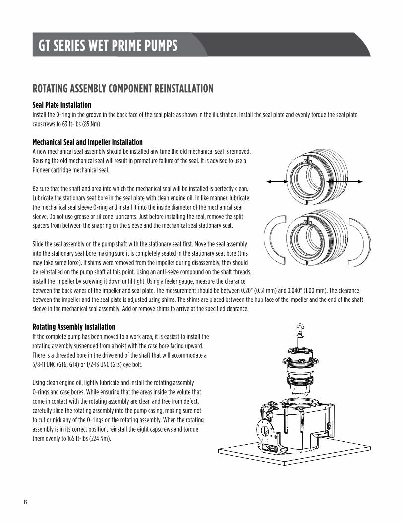
Mechanical Seal and Impeller InstallationA new mechanical seal assembly should be installed any time the old mechanical seal is removed. Reusing the old mechanical seal will result in premature failure of the seal. It is advised to use a Pioneer cartridge mechanical seal.
Be sure that the shaft and area into which the mechanical seal will be installed is perfectly clean. Lubricate the stationary seat bore in the seal plate with clean engine oil. In like manner, lubricate the mechanical seal sleeve O-ring and install it into the inside diameter of the mechanical seal sleeve. Do not use grease or silicone lubricants. Just before installing the seal, remove the split spacers from between the snapring on the sleeve and the mechanical seal stationary seat.
Slide the seal assembly on the pump shaft with the stationary seat first. Move the seal assembly into the stationary seat bore making sure it is completely seated in the stationary seat bore (this may take some force). If shims were removed from the impeller during disassembly, they should be reinstalled on the pump shaft at this point. Using an anti-seize compound on the shaft threads, install the impeller by screwing it down until tight. Using a feeler gauge, measure the clearance between the back vanes of the impeller and seal plate. The measurement should be between 0.20" (0.51 mm) and 0.040" (1.00 mm). The clearance between the impeller and the seal plate is adjusted using shims. The shims are placed between the hub face of the impeller and the end of the shaft sleeve in the mechanical seal assembly. Add or remove shims to arrive at the specified clearance.
Rotating Assembly InstallationIf the complete pump has been moved to a work area, it is easiest to install the rotating assembly suspended from a hoist with the case bore facing upward. There is a threaded bore in the drive end of the shaft that will accommodate a 5/8-11 UNC (GT6, GT4) or 1/2-13 UNC (GT3) eye bolt.
Using clean engine oil, lightly lubricate and install the rotating assembly O-rings and case bores. While ensuring that the areas inside the volute that come in contact with the rotating assembly are clean and free from defect, carefully slide the rotating assembly into the pump casing, making sure not to cut or nick any of the O-rings on the rotating assembly. When the rotating assembly is in its correct position, reinstall the eight capscrews and torque them evenly to 165 ft-lbs (224 Nm).

14
GT SERIES WET PRIME PUMPS
FLAPPER VALVE SERVICERemovalRemove the two casing screws on the flapper access port cover. While taking care not to cut or nick the flapper cover O-ring, remove the flapper access port cover. Make certain that the vent port O-ring stays in its counterbore unless replacement is required.
Remove the flapper retention pin, followed by the flapper valve, through the flapper port. The flapper valve cannot be disassembled. If replacement of the flapper valve is required, the associated hardware must also be replaced .
ReplacementInstall a new flapper assembly and reinstall the flapper retention pin. By applying a small amount of grease to the flapper access port O-ring groove, the O-ring will be retained in the groove during assembly. Ensure that both the flapper valve access cover and vent port O-rings are seated properly in their groove or counterbore before reinstalling the flapper access port cover.
Replace the flapper access port cover, being careful not to cut or nick the flapper cover O-ring. Install and hand-tighten the two casing screws.
VOLUTE INSPECTIONInspect the inside of the volute, looking for excessive wear or damage to any part of the interior. Particular attention should be paid to checking the cutwater for wear and the reprime port to ensure it is not blocked in any way.
Casing Screws
Flapper Access Port Cover
Flapper Cover O-ring
Flapper Valve
Vent Port O-ring
Flapper Valve Retention Pin

15
GT SERIES WET PRIME PUMPS
APPENDICESBolt Torque Chart
SIZE UNC WRENCH304 SS (MARKINGS VARY) GRADE 5 GRADE 8
FT-LBS (NM)1/4 7/16 3 / 4 9 / 12 13 / 18
5/16 1/2 7 / 9 19 / 26 27 / 373/8 9/16 13 / 17 34 / 46 48 / 657/16 5/8 20 / 27 54 / 73 77 / 1041/2 3/4 31 / 42 83 / 113 117 / 159
9/16 13/16 45 / 61 120 / 163 170 / 2305/8 15/16 63 / 85 165 / 224 234 / 3173/4 1-1/8 112 / 152 293 / 397 415 / 5637/8 1-5/16 180 / 244 474 / 643 670 / 908
1 1-1/2 270 / 366 710 / 963 1000 / 13561-1/4 1-7/8 540 / 732 1421/ 1927 2000 / 2711
Lubricating Oil and CapacitiesThe GT Series Pump uses Viscosity Grade ISO32 Turbine Oil in all compartments.
COMPARTMENT GT3 GT4 GT6Bearing Housing 0.75 qt / 0.70 l 0.75 qt / 0.70 l 1 qt / 0.95 l
Seal Reservoir 1.5 qt / 1.4 l 2.75 qt / 2.6 l 3.7 qt / 3.5 l
GreaseThe GT Series pumps use grease as a barrier and lubricant between the double lip seals at the drive end of the pump. Any automotive- or industrial-duty bearing grease is sufficient.
Technical Specifications and DimensionsCOMMON TORQUE VALUES (FT-LBS / NM)
PART GRADE 5 STEEL STAINLESS STEELWear Plate to Inspection Cover 34 / 46 13 / 18
Inspection Cover to Pump Casing 165 / 224 N/ABearing Cap to Bearing Housing 165 / 224 N/A
Seal Plate to Bearing Housing 34 / 46 13 / 18Rotating Assembly to Pump Casing 165 / 224 N/A
OPERATING CLEARANCES (IN / MM)
PART CLEARANCEPump Shaft End Play 0.002 / 0.05 – 0.010 / 0.25Impeller to Seal Plate 0.20 / 0.51 – 0.040 / 1.00
APPROXIMATE COMPONENT WEIGHTS (LBS / KG)
PART GT 3 GT4 GT6Bare Shaft Pump 545 / 248 700 / 318 975 / 442
Inspection Cover Assembly 51 / 23 58 / 26 100 / 45Impeller 15 / 9 14 / 6 43 / 20
Rotating Assembly 150 / 68 180 / 82 270 / 123Shaft and Bearing Assembly 20 / 9 36 / 16 49 / 22

16
GT SERIES WET PRIME PUMPS
NOTES ___________________________________________________________________________________________________
___________________________________________________________________________________________________
___________________________________________________________________________________________________
___________________________________________________________________________________________________
___________________________________________________________________________________________________
___________________________________________________________________________________________________
___________________________________________________________________________________________________
___________________________________________________________________________________________________
___________________________________________________________________________________________________
___________________________________________________________________________________________________
___________________________________________________________________________________________________
___________________________________________________________________________________________________
___________________________________________________________________________________________________
___________________________________________________________________________________________________
___________________________________________________________________________________________________
___________________________________________________________________________________________________
___________________________________________________________________________________________________
___________________________________________________________________________________________________
___________________________________________________________________________________________________
___________________________________________________________________________________________________
___________________________________________________________________________________________________

17
GT SERIES WET PRIME PUMPS
NOTES ___________________________________________________________________________________________________
___________________________________________________________________________________________________
___________________________________________________________________________________________________
___________________________________________________________________________________________________
___________________________________________________________________________________________________
___________________________________________________________________________________________________
___________________________________________________________________________________________________
___________________________________________________________________________________________________
___________________________________________________________________________________________________
___________________________________________________________________________________________________
___________________________________________________________________________________________________
___________________________________________________________________________________________________
___________________________________________________________________________________________________
___________________________________________________________________________________________________
___________________________________________________________________________________________________
___________________________________________________________________________________________________
___________________________________________________________________________________________________
___________________________________________________________________________________________________
___________________________________________________________________________________________________
___________________________________________________________________________________________________
___________________________________________________________________________________________________

18
GT SERIES WET PRIME PUMPS
NOTES ___________________________________________________________________________________________________
___________________________________________________________________________________________________
___________________________________________________________________________________________________
___________________________________________________________________________________________________
___________________________________________________________________________________________________
___________________________________________________________________________________________________
___________________________________________________________________________________________________
___________________________________________________________________________________________________
___________________________________________________________________________________________________
___________________________________________________________________________________________________
___________________________________________________________________________________________________
___________________________________________________________________________________________________
___________________________________________________________________________________________________
___________________________________________________________________________________________________
___________________________________________________________________________________________________
___________________________________________________________________________________________________
___________________________________________________________________________________________________
___________________________________________________________________________________________________
___________________________________________________________________________________________________
___________________________________________________________________________________________________
___________________________________________________________________________________________________

FORM 2102 REV. 0 06-16 pioneerpump.com | 503.266.4115