gtd111 alloy material study - asmeproceedings.asmedigitalcollection.asme.org/data/...temperature of...
TRANSCRIPT

THE AMERICAN SOCIETY OF MECHANICAL ENGINEERS 345 E. 47th St., New York, N.Y. 10017 96•GT-520
The Society shall not be responsible for statements or opinions advanced In papers or discussion at meetings of the Society or of Its Divisions or Sections, or printed In its publications. Discussion is printed only If the paper is published In an ASME Journal. Authorization to photocopy material for internal or personal use under circumstance not falling within the lair use provisions of the Copyright Act is granted by ASME to libraries and other users registered with the Copyright Clearance Center (CCC) Transactional Reporting Service provided that the base lee of $0.30 per page Is paid directly to the CCC, 27 Congress Street, Salem MA 01970. Requests tor special permission or bulk reproduction should be addressed to the ASME Technical Publishing Department.
Copyright 0 1996 by ASME
All Rights Reserved Printed In U.S.A
GTD111 ALLOY MATERIAL STUDY
Joseph A. Daleo Wilson & Daleo Inc. Ancaster, Ontario
Canada
James R. Wilson Wilson & Daleo Inc. Ancaster, Ontario
Canada
1111111111 111)1111111111
ABSTRACT Very little property data on this common turbine
blade alloy has been published. As longer hours of service are accumulated, maintenance considerations such as developing optimum component life strategies and repair processes become important. The lack of specific material data hampers the effort of users and repair facilities to achieve optimum service from this alloy.
This study measured some of the basic mechanical and metallurgical characteristics of this poly-crystalline nickel base superalloy. Tensile and short term creep rupture properties as well as microstructural and fracture characteristics are presented. Both the as-heat-treated and thermally exposed characteristics at two different temperatures are examined.
INTRODUCTION The poly-crystalline nickel base superalloy,
GTD111, developed by General Electric (GE) is used extensively for high temperature rotating buckets in land based gas turbines. At present, for a standard gas turbine material, only a minimum amount of information detailing the metallurgical and mechanical properties of the alloy have been published. General Electric has published the nominal chemistry and has indicated that the alloy has approximately a 20°C creep rupture advantage over the industry standard blading material IN-738LC alloy (1)(6). Beyond this no other
technical information is available on the alloy.
Examination of the published GTD111 alloy composition suggests that the alloy is a derivative of the successful aircraft blade alloy Rene 80. The chemical compositions are the same except for slight modifications to the proportions of the elements C, Ta, and Mo which were modified to improve the hot corrosion properties.
Evaluation of service exposed GTD111 components as to their suitability for repair or re-use is hampered by the lack of published microstructural and mechanical property data and by limited experience with this particular material outside the manufacturer. This research program was developed to understand the material's long term metallurgical aging characteristics and to generate enough basic material properties to reliably provide engineering services. The information gained from the experiments is directly applicable to the analysis and repair of General Electric rotating buckets in Frame 3, 5, 6,7 and 9 engine models.
EXPERIMENTAL PROGRAM The experiments and tests conducted were
designed to identify some of the basic mechanical and metallurgical property characteristics of the GTD111 alloy. The material was characterized in the standard heat treated condition and after thermal exposures that bracket the operating
Presented at the International Gas Turbine and Aeroengine Congress & Exhibition Birmingham, UK — June 10-13, 1996
This paper has been accepted for publication in the Transactions of the ASME Discussion of it will be accepted at ASME Headquarters until September 30, 1996
Downloaded From: http://proceedings.asmedigitalcollection.asme.org/ on 06/14/2018 Terms of Use: http://www.asme.org/about-asme/terms-of-use

temperature of the material in typical gas turbine rotating bucket applications. Sample material was aged at 816°C (1500°F) and 899°C (1650°F) for 5,000 hours. The test program was designed to determine the effect of the thermal exposures on the mechanical properties of the alloy and to determine the microstructural stability of the material. The results, including the ageing characteristics, were then compared to Rene 80 alloy. If the alloy had similar mechanical and aging properties as Rene 80, the extensive published data base for Rene 80 could be substituted for this alloy with reasonable confidence. If the alloy showed significant differences, further work would be required to understand the long term aging effects and mechanical properties.
INVESTIGATION 1. GTD111 LITERATURE SEARCH
A literature and patent search for relevant published data did not reveal any useful information. Apparently no U.S. or Canadian patents have yet been issued for the alloy (1994).
2. ACQUISITION OF SAMPLE MATERIAL The root forms of MS6001B engine run first
stage buckets were used as starting material for the study. The metal temperatures experienced by the root forms during operation are relatively low (< 538°C), thus the microstructural features and starting mechanical properties do not significantly change during service. This makes the root form material representative of the original chemistry and manufacturing process used to make the buckets and suitable starting material for the experiments. A photograph of a typical bucket used in the study is illustrated in Figure 1.
Nine buckets were used in the program. The buckets were selected so that different heats of material would be represented in the testing program, providing as broad a cross section of initial starting conditions as possible . The following buckets were made available for the study.
SERIAL NUMBER HEAT CODE EIFM204757 VAF141 EIFM179744 VAF125 EIFM193232 VAF135 EIFM203610 VAF 136
EIFM203785
VAF136 EIFM192260
VAF135 EIFM203939
VAF140 EIFM185892
VAF125 EIFM174645
VAF 124
3. CHEMICAL ANALYSIS Quantitative chemical analysis of bucket serial
number EIFM174645 was performed (Table l). The acceptable chemistry range was estimated from the published Rene 80 composition. The chemistry of the remaining GTD111 first stage buckets used in the program were characterized by their heat codes and in the Scanning Electron Microscope , using an Energy Dispersive X-ray Analyzer.
4. MICROSTRUCTUFtAL ANALYSIS Knowledge of the alloy microstructure is
fundamental to understanding the mechanical property behaviour of the material. Superalloy microstructures never reach a state of equilibrium. They continually change with time at the operating temperatures experienced in most gas turbine applications.
The starting microstructure of the GTD111 buckets is a product of the chemistry, the casting parameters, coating and heat treatment steps used to manufacture the component. The buckets used in this study were vacuum investment cast, hot isostatically pressed , machined and processed through the General Electric GT29PLUS INCOAT coating process and the General Electric GTD111 alloy standard heat treatment.
The microstructurel features generated by the processing were similar to other nickel based superalloy casting alloys previously described by C. T. Sims et al (2). In general, all of the bucket castings examined appeared to be of high quality. No excessively large grains, porosity, or areas of gross shrinkage were observed. The lack of porosity in the microstructure indicates that the buckets were hot isostatically pressed as part of the original manufacturing sequence.
Samples examined from bucket serial number EIFM174645 in the SEM revealed that the GTD111 microstructure in the standard heat treated condition consisted of a duplex gamma prime (7')
2
Downloaded From: http://proceedings.asmedigitalcollection.asme.org/ on 06/14/2018 Terms of Use: http://www.asme.org/about-asme/terms-of-use

(Ni3(AI,Ti) precipitate evenly distributed in the face centred cubic(FCC) gamma (y) matrix (Figure 2). The average size of the primary y' precipitates was 0.86 micron and the average size of the secondary y' precipitates was 0.1 micron. The grain boundaries were decorated with a very thin, discontinuous y7 M23C6/M6C carbide layer (Figure 3). Scattered throughout the matrix and occasionally on the grain boundaries were eutectic y' nodules and MC carbides(Ta,Ti,VV). The grain boundaries were not finely serrated, however they were wavy on a macro scale. Eutectic y' and MC carbides were present both along the grain boundaries and evenly distributed throughout the matrix.
The stability of the various microstructural phases at the operating temperatures experienced by gas turbine buckets are extremely important. In service the y' phase increases in size with time and temperature and complex carbide reactions occur. The most important of the carbide reactions is the continued growth of the M23C6 carbide phase along the grain boundaries. The migration of chromium to the boundary leaves the matrix locally enriched in the y' forming elements nickel, aluminum, titanium etc. allowing a film of y' to form along the boundary. Degeneration of MC carbides into M23C6
+y' in the matrix and along the grainboundaries accelerates the process. Examples of these phase changes were observed in the microstructure of the buckets aged at 816°C (1500°F) and 899°C (1650°F) for 5,000 hours as well as in service exposed material.
A Scanning Electron Micrograph of bucket EIFM192260 illustrating the microstructure after a 5,000 hour thermal exposure at 816°C (1500°F) is presented in Figure 4. While the primary y' particles had not significantly grown in size during the thermal exposure, they had started to transform from cube shaped particles to a more rounded morphology. The size of the primary y' precipitates had grown from an average size of 0.86 micron to 0.95 micron. The secondary yi precipitates were dissolved. The grain boundary carbides were starting to coarsen and coalesce. Continuous y'/ M23C6 films had formed.
The microstructure of bucket EIFM204757 after
a 5,000 hour thermal exposure at 899°C ( 1650°F) is presented in Figure 5. The primary y' precipitates had transformed from cubic shaped particles to a rounded morphology. The size of the primary y' precipitates had grown from an average size of 0.86 micron to 1.16 micron. The secondary y' precipitates were consumed. The grain boundary carbides had coarsened and coalesced. Thick continuous y'/ M23C6 films had formed. Figure 6 illustrates the eutectic gamma prime and MC carbides present along the grain boundaries as well as throughout the matrix. Note the degeneration of the MC carbide along the grainboundary.
The microstructure of a GTD111 turbine bucket removed from service after approximately 23,000 hours is presented in Figures 7 and 8. Note that the growth of matrix y' , the grain boundary carbides and the formation of yi films along the boundaries is continuing. Although y' formation along grainboundaries is normal and in most cases beneficial, when the films become too thick, the boundary is imbrittled becomes notch sensitive and is prone to cracking (Figure 9). Continued growth of the y' phase reduces the creep resistance of the material.
5. MECHANICAL TESTING 5.1 TENSILE TESTING
Tensile samples from bucket serial numbers EIFM179744 and EIFM193232 were tested at the following parameters per ASTM E8 (3): 21°C (70°F) 649°C (1200°F) 732°C (1350°F) 816°C (1500°F) 982°C (1800°F)
The Ultimate Tensile Strength, 0.2% Offset Yield Strength, Percent Elongation and Percent Reduction of Area were measured and are reported in Table II.
5.2 CREEP RUPTURE TESTING Creep rupture samples from bucket serial
numbers EIFM179744, EIFM193232 and EIFM174645 were tested at the following parameters per ASTM E139 (4) : 816°C / 565.4 MPa (1500°F /82 KSI) 816°C /482.6 MPa (1500°F / 70 KSI) 871°C / 372.3 MPa (1600°F / 54 KSI) 871°C / 296.5 MPa (1600°F / 43 KSI) 982°C /189.6 MPa (1800°F / 27.5 KSI)
Downloaded From: http://proceedings.asmedigitalcollection.asme.org/ on 06/14/2018 Terms of Use: http://www.asme.org/about-asme/terms-of-use

Comparative creep rupture properties at the same test parameters were generated from buckets serial numbers EIFM192260 and EIFM204757 after 5,000 hour thermal exposures at 816°C (1500°F) and 899°C (1650°F).
The hours to failure, Percent Elongation, Percent Reduction of Area, Minimum Creep Rate, and resulting Larson Miller Parameters of the samples tested in the standard heat treated condition are reported in Table III. The creep rupture properties of the thermally exposed material are presented in Table IV.
Plots of Percent Creep Deformation (strain) versus time for the creep rupture samples tested are illustrated in Figures 10 to 14. Compared to the material properties in the standard heat treated condition, the creep rupture properties of GTD111 alloy had significantly degraded after the 5,000 hour thermal exposures at both 816°C and 899°C with the rupture life and minimum creep rates decaying more after the 899°C exposure. The creep ductilities, however, were still acceptable. The difference in the drop in properties between the 816°C and 899°C test points was not as large as one might expect considering the extent of microstructural changes that had occurred at 899°C compared to the 816°C exposure. In GTD111 material that has received the appropriate heat treatments, the gamma prime particles and grain boundary carbides are arranged in a structure that results in the optimum creep properties. When the alloy is exposed to gas turbine operating conditions, or in this case during laboratory exposures, microstructural changes occur. The dissolution of the secondary gamma prime precipitates and the increase in the size of the strengthening gamma prime particles tends to lower the creep strength and possibly the fatigue resistance of the material. The formation of the thick continuous y'/ M23C6 films weaken the grain boundaries and act as primary pathways for fracture. Similar ageing effects have been reported to reduce mechanical properties in Rene 80 alloy (7)..
The GTD111 alloy creep rupture samples tested at the Rene 80 qualification parameters 982°C / 189.6 MPa (1800°F /27.5 KSI) in the standard heat treated condition passed the minimum
requirements of the test. While the creep rupture properties of the thermally exposed samples had dropped significantly, the test samples both passed the minium requirements of the test. The inability of the test parameters to discriminate between the material conditions indicates that testing GTD111 alloy at the common Rene 80 qualification parameters would not be a valid acceptance test to re-qualify refurbished material that has been coated and re-heat treated.
The Rene 80 stress rupture qualification test parameters were originally designed as quality control tests to screen out chemistry lots/heat treatment cycles that produce material outside of the Rene 80 material scatter band. The stress rupture specification (4), for Rene 80 material, given the standard heat treatment requires a minimum time to rupture of 23 hours with 5% reduction in area. The GTD111 alloy acceptance test parameters are not currently available.
6.0 FRACTURE CHARACTERISTICS The fracture surfaces of the creep rupture
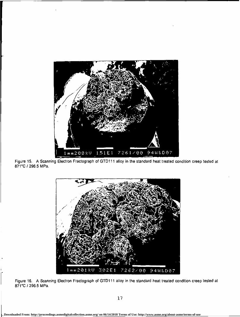
samples were examined in the SEM and by metallographic methods. The primary fracture mode of all of the samples examined was wedge cracking along intergranular fracture paths with the cracks linking up to form shear walls during the final overload failure (Figures 15 and 16). At the 871°C (1600°F) test temperature, the cracking mechanism was assisted by oxidation of the grain boundaries (Figures 17 and 18). The occasional cracked MC carbide was observed at or just below the fracture surfaces. Very little secondary cracking was observed in all of the samples examined except for the samples tested at 871°C/296.5 MPa (1600°F/43 KSI). These samples were failing along multiple intergranular fracture paths.
DISCUSSION 1. MECHANICAL PROPERTY ANALYSIS
A tensile test property versus temperature plot comparing Rene 80 alloy and the GTD111 alloy test data in Table II is illustrated in Figure 19. The tensile curves are almost identical indicating that GTD111 alloy behaves similarly to Rene 80. Using Rene 80 tensile properties for GTD111 alloy appears to be an acceptable procedure for new material given the standard heat treatment.
4
Downloaded From: http://proceedings.asmedigitalcollection.asme.org/ on 06/14/2018 Terms of Use: http://www.asme.org/about-asme/terms-of-use

A Larson Miller curve (5) constructed from the GTD111 alloy test data in Table III is plotted in Figure 20. A Larson Miller Plot comparing the GTD111 alloy test points and Rene 80 data from the literature with points picked off the GTD111 Larson Miller curve published by General Electric(6) is presented in Figure 21. The GTD111 / Rene 80 alloy Larson Miller curves appear to be identical.
A least squares regression model (Y=13 0+0 1 X+e) was fitted to the GTD111 creep rupture data presented in the Larson Miller form. The least squares fit, the 95% confidence intervals about the mean and the 95% prediction interval for an individual observation were calculated and plotted in Figure 22. For a first order estimate of the confidence limits using limited data the model was a good fit of the experimental and published data. More low stress, intermediate temperature (816°C to 899°C), long term creep data points are needed to accurately fit the lower end of the curve.
The creep rupture data points measured after the 5,000 hour laboratory thermal exposures at 816°C and 899°C are also plotted in Figure 22. The creep rupture properties have dropped below the 95% confidence interval of the mean as well as the individual prediction levels at the 816°C/565.4 MPa (1500°F/82 KSI) and 816°C/482.6 MPa (1500°F170 KSI) parameters. As the test temperature was increased and the testing stress reduced, the deterioration of the aged properties did not appear to be as significant. The wide discrepancy in the rate of creep rupture property deterioration between the lower temperature, higher stress creep rupture properties and the high temperature, lower stress properties was likely due to the nature of the test. At the higher test temperatures the secondary gamma prime particles are quickly dissolved and their strengthening effect is not included in the test result either before or after the thermal exposure. However, at the lower temperature, higher stress parameters, the secondary gamma prime precipitates are not dissolved during the short duration of the test. The difference in the mechanical properties before and after the thermal exposures can be attributed to the dissolution of the • secondary gamma prime precipitates.
Stress rupture data points measured from service
exposed GTD111 Frame 6 and Frame 7 first stage buckets are also plotted in Figure 22. Note that some of the service exposed points are well outside the 95% confidence interval of the mean. Experience with GTD111 material removed from service has revealed a loss in creep ductility as well as creep life. This may imply that the material is being imbrittled by oxygen effects previously described by Woodford (8).
2. TEMPERATURE ESTIMATION USING THE y'
GROWTH RATE METHOD The rate of gamma prime (y) coarsening in
superalloys including Rene 80 (9) has been reported to follow diffusion controlled coarsening kinetics. The data generated from the experiments define the GTD111 y' coarsening kinetics and . allowed the rate constants to be calculated. The model was then adapted to estimate metal temperatures of service run components. '
The rate of gamma prime (y') coarsening follows the diffusion controlled coarsening kinetics• described by Chellman and Ardell (10).
(rF S-rs3) 1/2=Kt1/4 1
Where t is time in seconds, r r is the average y' radius in nanometres at time t, r s is the average starting y'radius at time 0 and K is a constant.
The rate constant K is independent of volume fraction and contains many important quantities including the temperature information. In its simplest form the rate constant can be expressed as follows (11):
InK3T = B-Q/RT 2
Where T is absolute temperature, Q is the activation energy for diffusion, R is the gas constant, and B is a constant. A plot of In(K 3T) versus 1/T results in a straight line with Q/R as the slope. Once 0 is known T can be estimated.
The activation energy for diffusion has been reported in the literature for both simple systems such as Al in Ni and Ti in Ni as well as complex superalloys such as IN-738, U500 etc. The reported activation energy ranged from 2.57 to 2.83 x 10⁵
Downloaded From: http://proceedings.asmedigitalcollection.asme.org/ on 06/14/2018 Terms of Use: http://www.asme.org/about-asme/terms-of-use

Joules/mole. The activation energy for diffusion calculated for GTD111 alloy in this experiment was 2.59 x 10⁵ Joules / mole. This compares
favourably with the published data indicating that this material behaves similarly to the other basic superalloy systems and that temperature estimation based on gamma prime growth laws is a viable tool using this alloy system.
In practice this model has been used effectively to estimate metal temperatures of service run components manufactured from GTD111, IN-738LC, Udimet 520 and Udimet 710/720 alloy systems.
CONCLUSIONS The creep rupture and tensile data generated
indicates that the strength of GTD111 material is virtually identical to the published Rene 80 data. This indicates that until a more thorough GTD111 alloy data base is generated or becomes available in the open literature, Rene 80 alloy properties can be substituted for GTD111 alloy provided that the GTD111 material is in the standard heat treated condition.
Compared to GTD111 alloy, in the standard heat treated condition, the short term creep rupture properties of the material had degraded after 5,000 hour thermal exposures at both 816°C (1500°F) and 899°C (1650°F). The creep rupture lives and minimum creep rates decayed slightly more after the 899°C exposure than the 816°C exposure.
The experimental data indicated that testing GTD111 alloy at the common Rene 80 stress rupture qualification parameters designed for accepting Rene 80 material would not be a valid acceptance test to re-qualify refurbished GTD111 material.
The rate of GTD111 gamma prime coarsening observed in the experiments compared favourably with the published data for other basic Ni,(AlTi) superalloy systems. Temperature estimation based on gamma prime growth laws was evaluated and proved to be a viable tool in evaluating GTD111 alloy. Temperature estimates accurate to approximately ± 20°C are possible assuming that the aging rate is independent of gamma prime
volume fraction and that material is exposed at relatively constant temperature.
RECOMMENDATIONS The GTD111 alloy material study should be
continued. The thermal exposures at typical bucket operating temperatures should be continued past 10,000 hours and the metallurgical and mechanical properties re-evaluated using standard methods.
Long term creep rupture tests should be conducted on material in the standard heat treated condition to improve the Larson Miller Curve and to further asses the long term aging characteristics of the material.
Regenerative heat treatments to restore the metallurgical and mechanical properties of service run GTD111 buckets should be developed and evaluated. Complete sets of used components should be processed and returned to service as part of the program.
A second testing program designed to develop coated and thin wall GTD111 alloy mechanical properties should also be started.
ACKNOWLEDGEMENTS This work was partially funded by the National
Research Council of Canada's Industrial Research Assistance Program. The contributions of Ron Natole of Natole Turbine Enterprises and David Hodgson and Chris Butcher of McMaster University's Institute for Materials Research are also greatly appreciated.
REFERENCES 1. GE Power Systems, Turbine Technology Reference Library, GER-3569. 2. Superalloys II, A Wiley-lnterscience publication, edited by C.T. Sims, N.S. Stoloff, W.C. Hagel, 1987. 3. Standard Test Methods of Tension Testing of Metallic Materials, ASTM E8. 3. Standard Practice for Conducting Creep, Creep Rupture, and Stress Rupture Tests, ASTM E139. 4. Aerospace Structural Metals Handbook Specification #4217, Rene 80 alloy. 5. F.R. Larson and J. Miller: Trans. ASME 74, 765 (1952).
6
Downloaded From: http://proceedings.asmedigitalcollection.asme.org/ on 06/14/2018 Terms of Use: http://www.asme.org/about-asme/terms-of-use

6. P.W. Schilke, A.D. Foster., J.J. Pepe, and A.M. Beltran, Advance Materials Propel Progress in Land-Base Gas Turbines, Advanced Materials And Processes, ApriU1992. 7. Low cycle Fatigue Of Rene 80 as Affected by Prior Exposure, S. Antolovich, P. Domas, J. Strudel, Metallurgical Transactions A, Volume 10A, December 1979. 8. Environmental Damage of a Cast Nickel Base Superalloy, D.A. Woodford, Metallurgical Transactions A, Vol 12A, February 1981. 9. H. J. Kolkman, Creep, Fatigue and their Interaction in Coated and Uncoated Rene 80, Materials Science and Engineering, 89 (1987) 81-91. 10. Chellman, D.J. and Ardell A.J. "The coarsening of y' Precipitates at Large Volume Fractions". Acta Met; 22 (1974), 577 to 588. 11. Stevens, R.A. and Flewitt, P.E.J.; "The effects of y' Precipitate Coarsening During Isothermal Ageing and Creep of the Nickel-Base Superalloy IN-738".Mat.Sci.and Eng., 37(1979), 237-247.
Downloaded From: http://proceedings.asmedigitalcollection.asme.org/ on 06/14/2018 Terms of Use: http://www.asme.org/about-asme/terms-of-use

TABLE I CHEMICAL COMPOSITION
ELEMENT EIFM174645 WEIGHT (%)
ESTIMATED GTD-111 ALLOY LIMITS (%) ***
NOMINAL RENE 80 ALLOY LIMITS (%)
MINIMUM MAXIMUM MINIMUM MAXIMUM
Carbon 0.103 0.08 .12 .15 .19
Boron 0.015 0.01 .02 0.01 0.02
Chromium 13.78 13.7 14.3 13.7 14.3
Cobalt 9.21 9.0 10.0 9.0 10.0
Nickel Remainder Remainder Remainder
Molybdenum 1.54 1.3 1.7 3.7 4.3
Tungsten 3.70 3.5 4.1 3.7 4.3
Tantalum 2.88 2.5 3.1 - 0.01
Aluminum 3.02 2.8 3.2 2.8 3.2
Titanium 4.81 4.7 5.1 4.8 5.2
Zirconium 0.01 0.02 0,08 0.02 0.10
Hafnium 0.04 0.02 0.08 •**Limits base on nominal composition and Rene 80 tolerances
TABLE II GTD111 TENSILE TEST DATA
SERIAL NUMBER
TEST TEMP(°C)
UTS (MPa)
0.2% YS (MPa)
% ELONG %R A
E1FM179744 21 •1011 819 10.5 15.7
E1FM193232 21 953 836 8.8 17.7
E1FM179744 649 1109 756 12.6 18.5
E1FM193232 649 1143 724 13.7 14.7
E1FM179744 732 1031 783 13.0 21.0
E1FM179744 816 854 717 29.7 29.2
E1FM193232 816 860 678 22.8 38.1
E1FM193232 982 429 297 22.3 30.2
8
Downloaded From: http://proceedings.asmedigitalcollection.asme.org/ on 06/14/2018 Terms of Use: http://www.asme.org/about-asme/terms-of-use
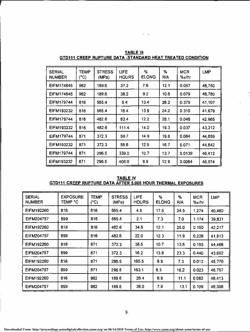
TABLE III GTD111 CREEP RUPTURE DATA -STANDARD HEAT TREATED CONDITION
SERIAL NUMBER
TEMP (°C)
STRESS (MPa)
LIFE HOURS
ok
ELONG %
R/A MCR %e/hr
LMP
E1FM174645 982 189.6 37.2 7.6 12.1 0.057 48,750
E1FM174645 982 189.6 38.2 9.2 10.6 0.079 48,780
E1FM179744 816 565.4 9.4 13.4 26.2 0.379 41,107
E1FM193232 816 565.4 18.4 13.9 24.2 0.310 41,679
E1FM179744 816 482.6 83.4 12.2 28.1 0.046 42,965
E1FM193232 816 482.6 111.4 14.0 19.3 0.037 43,212
E1FM179744 871 372.3 59.7 14.9 19.6 0.064 44,859
EIFM193232 871 372.3 58.6 12.9 16.7 0.071 44,842
E1FM179744 871 296.5 339.0 10.7 13.7 0.0139 !46,412
E1FM193232 871 296.5 406.0 9.9 12.9 0.0084 46,574
TABLE IV GTD111 CREEP RUPTURE DATA AFTER 5,000 HOUR THERMAL EXPOSURES
SERIAL NUMBER
EXPOSURE TEMP °C
TEMP (°C)
STRESS (MPa)
LIFE HOURS
% ELONG
% R/A
MCR %e/hr
LMP
E1FM192260 816 816 565.4 4.5 17.5 34.5 1.274 40,480
E1FM204757 899 816 565,4 2.1 7.3 7.0 1.174 39,831
EIFM192260 816 816 482.6 34.6 12.1 25.0 0.150 42,217
E1FM204757 899 816 482.6 22.0 12.3 11.9 0.226 41,813
E1FM192260 816 871 372.3 38.5 10.7 13.6 0.155 44,466
E1FM204757 899 871 372.3 16.2 13.8 23.3 0.440 43,692
EIFM192260 816 871 296.5 165.5 6.9 7.3 0.012 • 45,770
E1FM204757 899 871 296.5 163.1 8.3 16.2 0.023 46,757
E1FM192260 816 982 189.6 26.4 6.9 11.1 • 0.082 48,413
E1FM204757 899 982 189.6 26.0 7.9 13.1 0.109 48,398
Downloaded From: http://proceedings.asmedigitalcollection.asme.org/ on 06/14/2018 Terms of Use: http://www.asme.org/about-asme/terms-of-use

Figure 1. A photograph of a typical Frame 6 root form used for sample material in the experiments.
Figure 2. A Scanning Electron Micrograph of the 610111 microstructure in the standard heat treated condition illustrating the duplex gamma prime precipitates in the gamma matrix .
10
Downloaded From: http://proceedings.asmedigitalcollection.asme.org/ on 06/14/2018 Terms of Use: http://www.asme.org/about-asme/terms-of-use

•Figure 3. A Scanning Electron Micrograph of the GTD111 microstructure in the standard heat treated condition illustrating a typical grain boundary.
Figure 4. A Scanning Electron Micrograph illustrating the GTD111 microstructure after a 5,000 hour thermal exposure at 816°C (1500°F).
11
Downloaded From: http://proceedings.asmedigitalcollection.asme.org/ on 06/14/2018 Terms of Use: http://www.asme.org/about-asme/terms-of-use

10um20.0k0 5,00E7 7249/0A 94W&DC17
171173177,77—'3"rk,“.W.7:1
:crE
,
• as,„
41WV:=1-
sye,
• M-•
Figure 5. A Scanning Electron Micrograph illustrating the GTD111 microstructure after a 5,000 hour thermal exposure at 899°C ( 1650°F).
Figure 6. A Scanning Electron Micrograph of the GTD111 microstructure after a 5,000 hour thermal exposure illustrating eutectic gamma prime nodules and MC carbides present along the grain boundaries.
12
Downloaded From: http://proceedings.asmedigitalcollection.asme.org/ on 06/14/2018 Terms of Use: http://www.asme.org/about-asme/terms-of-use

I u m 0.n k I .1 5 CI nE7 5720/nn 9 5 WO, 0 3 5
um2UOkU 20 0E4 57 2 5/3n 95 1,1 0 7
Figure 7. A Scanning Electron Micrograph illustrating the GTD111 microstructure observed at the leading edge of a MS6001 first stage turbine bucket after approximately 23,000 hours of service.
Figure 8. A Scanning Electron Micrograph illustrating the GTD111 microstructure observed at the leading edge of a MS6001 first stage turbine bucket after approximately 23,000 hours of service.
13
Downloaded From: http://proceedings.asmedigitalcollection.asme.org/ on 06/14/2018 Terms of Use: http://www.asme.org/about-asme/terms-of-use

GTD111 ALLOY CREEP RUPTURE DATA TEST PARAMETERS 982 ° C/189.6 MPa
40 3 20 TEST TIME - HOURS
10
8
6
4
2
DE
FO
RM
AT
ION
- P
ER
CE
NT
EIFM174645, STANDARD HEAT TREAT —a— EIFM174645, STANDARD HEAT TREAT
—a— EIFM192260, 816 . C/5000 HOURS EIF4204757, 699'C/5000 HOURS
Figure 9 A photomicrograph illustrating a fractured grainboundary observed in a MS6001 first stage turbine bucket after approximately 23,000 hours of service (X 500).
Figure 10. A Plot of Percent Creep Deformation (strain) versus time for the creep rupture samples in the standard heat treated condition and after thermal exposures at 816°C and 899°C.
14
Downloaded From: http://proceedings.asmedigitalcollection.asme.org/ on 06/14/2018 Terms of Use: http://www.asme.org/about-asme/terms-of-use

' 10
GTD111 ALLOY CREEP RUPTURE DATA TEST PARAMETERS 816 ° C/565.4 MPa
5 10 TEST TIME - HOURS
15 20
18
16
-a- EIFMI79744, STANDARD HEAT TREAT -+- EIFM193232, STANDARD HEAT TREAT
-+- EIF1192260, 816 ° C/5,000 HOURS -0- EIFM204757, 899 °C15,000 HOURS
GTD111 ALLOY CREEP RUPTURE DATA TEST PARAMETERS 816 ° C/482 6 MPa
20 40 60 80
100
120 TEST TIME - HOURS
-0-- EIFM179744, STANDARD HEAT TREAT -0- EIFM193232, STANDARD HEAT TREAT
- 0- EIFM192260, 816'C/5,000 HOURS -0- EIFM204757, 899 °C/5,000 HOURS
16
14
2
Figure 11. A Plot of Percent Creep Deformation (strain) versus time for the creep rupture samples in the standard heat treated condition and after thermal exposures at 816°C and 899°C.
Figure 12. A Plot of Percent Creep Deformation (strain) versus time for the creep rupture samples in the standard heat treated condition and after thermal exposures at 816°C and 899°C.
15
Downloaded From: http://proceedings.asmedigitalcollection.asme.org/ on 06/14/2018 Terms of Use: http://www.asme.org/about-asme/terms-of-use

GTD111 ALLOY CREEP RUPTURE DATA TEST PARAMETERS 871 ° C/372 3 MPa
16
14
• MAinerr migiopm
0 10 20 30 40
50 TEST TIME - HOURS
EIF4179744, STANDARD HEAT TREAT EIFM193232, STANDARD HEAT TREAT
—•— EIFM192260, 816 ° C/5,000 HOURS —8— EIFM204757, 899 °C/5,000 HOURS
0 4
2
60
GTD111 ALLOY CREEP RUPTURE DATA TEST PARAMETERS 871°C/296.5 MPa
100 200 300 TEST TIME - HOURS
400
10
6 0
4
0
EIFM179744, STANDARD HEAT TREAT EIFM193232, STANDARD HEAT TREAT
EIFM192260, 816°C/5,000 HOURS _a_ EIFM204757, 899°C/6,000 HOURS
Figure 13. A Pot of Percent Creep Deformation (strain) versus time for the creep rupture samples in the standard heat treated condition and after thermal exposures at 816°C and 899°C.
Figure 14. A Plot of Percent Creep Deformation (strain) versus time for the creep rupture samples in the standard teat treated condition and after thermal exposures at 816°C and 899°C.
16
21 Downloaded From: http://proceedings.asmedigitalcollection.asme.org/ on 06/14/2018 Terms of Use: http://www.asme.org/about-asme/terms-of-use
41" \ s
1 m m 2 0.0 t:: I.) 1.5 1 E 1 7 2 iS 1 /1 El fil 9 4 1,1 :::: El 0 7
Figure 15. A Scanning Electron Fractograph of GTD111 alloy in the standard heat treated condition creep tested at 871°C / 296.5 MPa.
Figure 16. A Scanning Electron Fractograph of GTD111 alloy in the standard heat treated condition creep tested at 871°C /296.5 MPa.
,
17
Downloaded From: http://proceedings.asmedigitalcollection.asme.org/ on 06/14/2018 Terms of Use: http://www.asme.org/about-asme/terms-of-use

Figure 17. A photomicrograph of GTD111 alloy, exposed at 816°C for 5000 hours, creep tested at 871°C1296.5 MPa. illustrating that the intergranular fracture mechanism was assisted by oxidation of the grain boundaries ( X 150).
Figure 18. A photomicrograph of GTD111 alloy, exposed at 816 °C for 5000 hours, creep tested at 871°C1296 5 MPa. illustrating that the intergranular fracture mechanism was assisted by oxidation of the grain boundaries ( X 500) _
18
7 Downloaded From: http://proceedings.asmedigitalcollection.asme.org/ on 06/14/2018 Terms of Use: http://www.asme.org/about-asme/terms-of-use

GTD111 ALLOY TENSILE DATA SERIAL NUMBERS EIFm179744 EIFM193232
0 100 200 300 400 500 600 700 800 900 1000 TEST TEMPERATURE ° C
400
200
ST
RE
SS
MP
a
1200
1000
800
600
A •
ULTIMATE TENSILE STRENGTH • 0.2% OFFSET YIELD STRENGTH
RENE 80 UTS, PUBLISHED DATA RENE 80 YS, PUBLISHED DATA
GTD111 ALLOY LARSON MILLER PLOT
1000
6 • • • C
0 • Uhl
GUM AO
ST
RE
SS
(M
Pa
)
100 22 23 24 25 26 27
28
LARSON MILLER P=7(20+LOG t) X 10-3
• GTD111 STANDARD HEAT TREATMENT o EXPOSED 5000 HRS AT 816t
• EXPOSED 5000 HOURS AT 899t
Figure 19. A tensile test property versus temperature plot comparing the GTD111 test data with the Rene 80 alloy.
Figure 20. A GTD111 alloy Larson Miller Curve constructed from the test data presented in Tables Ill and IV.
19
Downloaded From: http://proceedings.asmedigitalcollection.asme.org/ on 06/14/2018 Terms of Use: http://www.asme.org/about-asme/terms-of-use

• GTD111 TEST DATA • GTD111 PUBLISHED DATA
• RENE 80 PUBLISHED DATA
RENE 80! GTD111 LARSON MILLER PLOT 1000
V. • To
gib
X X y
10 22 23 24 25 26 27 28
29
LARSON MILLER P=T(20+LOG t) X 10 3 30
29 30 22 23 24 25 26 27 28 LARSON MILLER P=T(20+LOG t) X 10 3
GTD111 ALLOY LARSON MILLER PLOT 1000
10
•
WV
GTD111 DATA + PUBLISHED RESULTS • SERVICE EXPOSED GTD111 DATA
a EXPOSED 5000 HOURS, 816t1 899 t
Figure 21. A Larson Miller plot comparing the GTD111 alloy test points with Rene 80 data from the literature and the GTD111 larson miller curve published by General Electric.
Figure 22. A least squares regression model (Y=80+81 X+e) fitted to the GTD111 creep rupture da a illustrating the fit, the 95% confidence 'ntervals about the mean and the 95% prediction interval for an individual observation. Test data ‘frarn the thermally exposed GTD111 material and select service exposed GTD111 data points are plotted.
20
Downloaded From: http://proceedings.asmedigitalcollection.asme.org/ on 06/14/2018 Terms of Use: http://www.asme.org/about-asme/terms-of-use