gti sub-6ghz 5g device white paper gti sub-6ghz … sub-6ghz 5g device white paper 4 table of...
TRANSCRIPT

GTI Sub-6GHz 5G Device White Paper
1
GTI
Sub-6GHz 5G Device
White Paper
http://www.gtigroup.org

GTI Sub-6GHz 5G Device White Paper
2
GTI Sub-6GHz 5G Device
White Paper
Version: V1.0
Deliverable Type □ Procedural Document
√ Working Document
Confidential Level √ Open to GTI Operator Members
√ Open to GTI Partners
□ Open to Public
Working Group Terminal WG
Task
Source members
Support members
Editor CMCC, Sprint
Last Edit Date 06-11-2017
Approval Date 10-11-2017

GTI Sub-6GHz 5G Device White Paper
3
Confidentiality: This document may contain information that is confidential and access to this
document is restricted to the persons listed in the Confidential Level. This document may not be
used, disclosed or reproduced, in whole or in part, without the prior written authorization of GTI,
and those so authorized may only use this document for the purpose consistent with the
authorization. GTI disclaims any liability for the accuracy or completeness or timeliness of the
information contained in this document. The information contained in this document may be
subject to change without prior notice.
Document History
Date Meeting # Version # Revision Contents
10-11-2017 v1.0 GTI Sub-6GHz 5G Device
DD-MM-YYYY
DD-MM-YYYY
DD-MM-YYYY
DD-MM-YYYY

GTI Sub-6GHz 5G Device White Paper
4
Table of Contents
1 Executive Summary ................................................................................................................... 6
2 Abbreviations ............................................................................................................................ 7
3 Introduction .............................................................................................................................. 9
4 References ................................................................................................................................. 9
5 Form Factor of 5G Device ........................................................................................................ 11
6 General Description ................................................................................................................ 14
6.1 System Description ....................................................................................................... 14
6.1.1 Key System Requirements ................................................................................. 14
6.1.2 Performance requirements ............................................................................... 15
6.2 Physical Layer Requirements ........................................................................................ 15
6.2.1 Multiple numerologies ...................................................................................... 16
6.2.2 Flexible frame structure .................................................................................... 16
6.2.3 Bandwidth part configuration and adaptation .................................................. 17
6.2.4 Initial access ....................................................................................................... 18
6.2.5 Waveform .......................................................................................................... 18
6.2.6 Modulation ........................................................................................................ 18
6.2.7 Multiple antenna techniques ............................................................................ 18
6.2.8 Scheduling and HARQ timing ............................................................................. 19
6.3 Upper Layer Requirements........................................................................................... 19
6.3.1 Control Plane ..................................................................................................... 19
6.3.2 User Plane .......................................................................................................... 20
6.4 Summary ...................................................................................................................... 21
7 Multi-Mode Multi-Band .......................................................................................................... 22
8 Network Access Capability ...................................................................................................... 25
8.1 Connectivity Options in 3GPP ...................................................................................... 25
8.1.1 Standalone NR ................................................................................................... 25
8.1.2 Non-Standalone NR ........................................................................................... 27
8.2 Uplink Strategies for NR deployment ........................................................................... 30
8.2.1 Uplink strategies for Standalone Operation ...................................................... 30
8.2.2 Uplink strategies for Non-Standalone Operation .............................................. 31
9 Inter-RAT Interworking ............................................................................................................ 31
9.1 NR mobility state transition ......................................................................................... 31
9.2 Inter-System Procedure ............................................................................................... 33
9.2.1 Interworking Procedures with N26 interface .................................................... 34
9.2.2 Interworking Procedures without N26 interface .............................................. 34
10 Voice Solution ......................................................................................................................... 35
10.1 Potential solutions ........................................................................................................ 36
10.2 Summary ...................................................................................................................... 37
11 RF Performance ....................................................................................................................... 38
11.1 High Power UE .............................................................................................................. 38
11.1.1 Motivation ......................................................................................................... 38
11.1.2 3GPP Status ....................................................................................................... 38

GTI Sub-6GHz 5G Device White Paper
5
11.1.3 TX Front-end Status and Architecture for HPUE ................................................ 38
11.1.4 Consideration on Thermal for HPUE .................................................................. 39
11.1.5 Consideration on SAR for HPUE ......................................................................... 40
11.2 In-Device Interference .................................................................................................. 41
11.3 SUL ................................................................................................................................ 44
11.4 LTE and 5G NR RF path co-banding .............................................................................. 44
11.4.1 Concept and Architecture of RF Path Co-banding ............................................. 45
11.4.2 System-level Challenges .................................................................................... 46
11.4.3 Way Forward on standalone support ................................................................ 48
11.4.4 Co-banding with simultaneous operation ......................................................... 48
12 Demodulation Performance .................................................................................................... 49
13 Power Consumption ................................................................................................................ 50
13.1 Introduction ................................................................................................................. 50
13.2 Key scenarios and performance metrics ...................................................................... 51
13.2.1 A figure of merit (FOM) for power consumption .............................................. 51
13.2.2 The power vs latency trade-off ......................................................................... 51
13.2.3 Achieving power efficient VoNR and ViNR ........................................................ 53
13.2.4 Spectrum usage for NR ...................................................................................... 53
13.3 Power scaling from LTE to NR ...................................................................................... 54
13.3.1 Example power breakdown for an LTE UE ........................................................ 54
13.3.2 RF front end ....................................................................................................... 54
13.3.3 Transceiver subsystem ...................................................................................... 55
13.3.4 Baseband processing ......................................................................................... 55
13.4 Managing UE power efficiently .................................................................................... 56
13.4.1 Overtemperature protection ............................................................................. 56
13.4.2 Bandwidth adaptation ....................................................................................... 56
13.4.3 Cross-slot scheduling ......................................................................................... 56
13.4.4 Power vs data rate ............................................................................................. 56
13.5 Implications for NR UEs ................................................................................................ 58
14 Test Requirements .................................................................................................................. 59
14.1 Test areas for 5G sub-6G and challenges ..................................................................... 59
14.1.1 Test challenges ................................................................................................... 59
14.1.2 Requirement for test equipment ....................................................................... 59
14.2 Device test cycle and test solutions ............................................................................. 60
14.3 Risks .............................................................................................................................. 61
15 Other Aspect ........................................................................................................................... 62

GTI Sub-6GHz 5G Device White Paper
6
1 Executive Summary
In recent years, 4G has profoundly changed our daily life, and stimulate people’s desire for
higher performance and better user experience for more innovative services and
applications. Towards 2020, the mobile communication will rapidly penetrate to more and
more elements of the human’s daily life and the society’s operation, which will create the
opportunities for the mobile industry and other vertical industries. With the new capabilities,
e.g. extremely high data rate, extremely low latency and extremely high reliability, massive
connection and traffic density, the 5th generation mobile communication technology (5G)
will shine a light on the great change on both our daily life and the whole society’s operation.
Targeting for commercial launch of 5G in 2020, the global telecommunication operators,
network, chipset and device vendors, test instrument manufacturers and solution providers
are deeply involved to promote end-to-end maturity of standard and industry. 5G technology
development and trial activities comprise some main phases, such as Key technology
feasibility validation, Prototype development and trials, Pre-commercial product
development, Lab tests and Field trials for pre-commercial and commercial product,
Commercial Launch and so on.
In the face of 5G services and market trends, there are many key capabilities and
performance indicators for 5G network, base station and device. And there are also many
challenges for 5G Device Design and Implementation, so 5G Device Whitepaper is necessary
to define the technical requirements for 5G Device and direct the research and analysis on
key points. GTI encourages the industry partners to participate the 5G activities and work
together to make contributions to the 5G Device White Paper.

GTI Sub-6GHz 5G Device White Paper
7
2 Abbreviations
Abbreviation Explanation
2/3G The 2/3rd Generation Telecommunication
3GPP The 3rd Generation Partnership Project
4G The 4th Generation Telecommunication
5G The 5th Generation Telecommunication Technology
AR Augmented Reality
CC Component Carrier
CP Control Plane
CPE Customer Premise Equipment
DC Dual Connectivity
eMBB Enhanced Mobile Broadband
gNB NR node
GP Guard Period
IPv4 Internet Protocol version 4
IPv6 Internet Protocol version 6
LDPC Low Density Parity Check
MAC Medium Access Control
MCG Master Cell Group
ME Mobile Equipment
MIMO Multiple-Input Multiple-Output
mMTC Massive Machine Type Communication
mmWave Millimeter Wave
MN Master Node
MR Mixed Reality
MU-MIMO Multi-User MIMO
NAS Non Access Stratum
NG Core Next Generation Core Network
NR New Radio
NSA Non-Standalone
OFDM Orthogonal Frequency Division Multiplexing
PDCP Packet Data Convergence Protocol
PDN Packet Data Network
PLMN Public Land Mobile Network
GTI Sub-6GHz 5G Device White Paper
8
PoC Proof of Concept
RLC Radio Link Control
RRC Radio Resource Control
SA Standalone
SCG Secondary Cell Group
SN Secondary Node
SU-MIMO Single-User MIMO
UE User Equipment
UP User Plane
URLLC Ultra-Reliable and Low Latency Communications
VR Virtual Reality

GTI Sub-6GHz 5G Device White Paper
9
3 Introduction
Targeting for the 5G industrialization, this White Paper is necessary to facilitate the
development of 5G chipset/device and the corresponding test instruments. This document
targets enhanced Mobile Broadband (eMBB) scenario for Sub-6GHz 5G pre-commercial and
commercial products, which is conducted to be the technical references for the development
of chipset/device and the basis for the 5G pre-commercial and commercial products specs.
Form Factor of 5G Device, the communication functions and performance requirements of
5G devices are described in this White Paper. And it focus on discussion about the key
research points of 5G Device, including Multi-Mode Multi-Band, Network Access Capability,
Inter-working and Voice Solutions, RF Requirements, Demodulation Performance, Power
Consumption and Device Testing Requirements.
5G device will follow 3GPP 5G NR Release 15 and later releases. This document will be
updated according to the progress of 3GPP 5G NR standardization and the findings from the
development and trials.
4 References
The following documents contain provisions which, through reference in this text, constitute
provisions of the present document.
[1] 3GPP, RP-161266, 5G architecture options – full set, Deutsche Telekom
[2] 3GPP, TS 37.340, NR; Multi-connectivity; Overall description; Stage-2, v1.0.0
[3] 3GPP, TS 38.300, NR; Overall description; Stage-2, v1.0.0
[4] 3GPP, TR 36.824, Evolved Universal Terrestrial Radio Access (E-UTRA); LTE coverage
enhancements, v11.0.0
[5] 3GPP, R4-1700977, Discussion on High power UE for 3.5GHz 5G NR, CMCC
[6] 3GPP, R4-1706068, WF on high power UE for 3.5GHz, CMCC, Skyworks, Qorvo, Broadcom,
MediaTek, Vodafone, CATT, Huawei, HiSilicon, ZTE
[7] 3GPP, R2-1708011, Thermal mitigation in NR UEs, Mediatek
[8] 3GPP, R1-1710838, Cross-slot scheduling for UE power saving, Mediatek
[9] B. Murmann, "ADC Performance Survey 1997-2017," [Online]. Available:
http://web.stanford.edu/~murmann/adcsurvey.html.
[10] 3GPP, R1-167531, Area, power and latency comparison for NR high throughput decoder,
Qualcomm

GTI Sub-6GHz 5G Device White Paper
10
[11] M. Lauridsen, P. Mogensen, and L. Noël. Empirical LTE Smartphone Power Model with
DRX Operation for System Level Simulations, IEEE 78th Vehicular Technology Conference, Sep
2013
[12] 3GPP, R1-1612067, Evaluation of frame structure design for UE Power Consumption,
Qualcomm
[13] 3GPP, RP-142307, New SI proposal: Performance enhancements for high speed scenario,
NTT DOCOMO, INC., Huawei, HiSilicon, Dec. 2014
[14] 3GPP, R4-150554, High speed train scenarios, CMCC, Feb. 2015
[15] 3GPP, RP-152263, New WI proposal: Performance enhancements for high speed
scenario, NTT DOCOMO, INC., Huawei, HiSilicon, Dec. 2015
[16] 3GPP, TS36.101, User Equipment (UE) radio transmission and reception (Release 14),
V14.3.0
[17] 3GPP, R4-163272, Discussion on Doppler shift estimation in unidirectional HST SFN
channels, Intel, May. 2016
[18] 3GPP, R4-160775, UE performance enhancement under SFN channel, Huawei, HiSilicon

GTI Sub-6GHz 5G Device White Paper
11
5 Form Factor of 5G Device
There are three main classes of new 5G applications: Extreme Mobile Broadband (eMBB),
Ultra-Reliable Low Latency Communications (URLLC) and Massive Machine Type
Communication (mMTC). mMTC can mostly be fulfilled by modification and optimization of
existing cellular technologies (e.g. NB-IoT), however URLLC and eMBB require new
technologies to break new bandwidth and latency boundaries. These will unlock new,
potential applications and services that require 5G infrastructure. In this white paper we are
focused on potential use cases and applications of eMBB devices, potential use of URLLC is
also discussed.
5G infrastructure has significant benefits for a number of applications that are already
limited in some capacity by existing 4G services. However this is only the beginning, as every
generational shift that grants more capacity and speed always grants unforeseen and
unpredictable applications that will only be realized later.
Known applications that will benefit demand high bandwidth and/or ultra-low latency
include
1. Virtual, mixed and augmented reality
2. Autonomous driving
3. Infotainment services for public and private transportation
4. 360-degree, 4K/8K resolution live entertainment and sports
5. Alternative to landline fiber services
6. Game-streaming services
7. Thin/zero client for mobile devices
More information on these applications are provided below:
1. Augmented Reality (AR), Mixed Reality (MR) and Virtual Reality (VR) devices
One of the biggest upcoming technological revolutions is AR, MR or VR devices. Each has its
own unique applications and opportunities, but all are still in their infancy and currently
range from proof-of-concept devices to immature platforms. 5G eMMB can help unlock
further advancements to yield new opportunities.
As smartphone performance increases, they are transforming into devices that can be used
with VR/AR headsets. Currently, Google’s Tango technology uses a Visual Positioning Service1
(VPS) for in-door navigation, but it relies heavily on local Wi-Fi networks to define its location
and the spaces it maps out. Using 5G technologies will enable more consistent signal
coverage allowing VPS to be mapped via a combination of camera(s), cellular location and
GPS.

GTI Sub-6GHz 5G Device White Paper
12
Generally speaking, AR/MR/VR are all data rate hungry, which translates to power and
battery limitations in smartphones and wearable devices (for example: Samsung Gear VR or
Microsoft Hololens). A revolutionary 5G use-case could instead offload the AR/MR/VR sensor
inputs and graphics rendering to a Cloud server, which would require only a much simpler,
low power user-device that acts only as sensor recorder, 5G cellular transmitter and video
decoder. This design would significantly lower the cost of ownership, enabling a much
greater market potential and service-style models based on Cloud-server use time. However
to enable Cloud-based processing without upsetting user experience, 5G eMMB with lower
latency will be required as they provide the necessary streaming bandwidth and low reaction
time.
2. Autonomous driving
Autonomous driving will greatly depend on wireless connectivity. Enabling vehicles to
communicate with each others could result in considerably more efficient and safer use of
existing road infrastructure. If all the vehicles on a road were connected to a reliable network
incorporating a traffic management system, they could potentially travel at much higher
speeds and within greater proximity of each other without risk of accident. Potential dangers
spotted by the increasing number of vehicular sensors could immediately be relayed to other
vehicles in the vicinity.
While such systems would not require very high data bandwidth, providing a reliable
infrastructure with a low response time would be crucial for their safe operation. Such
applications require the millisecond-level response addressed in the 5G specification.
3. Infotainment services for public and private transport
While current personal media needs are mostly being serviced by smartphones and tablets,
private vehicles increasingly have infotainment functions built in as natural extension to the
legacy of radio, CD and DVD. While air travel has embraced in-seat infotainment for many
years and subscription based services for private vehicles is gaining traction, public ground
transportation services could also provide in-seat infotainment as a source of additional
revenue. Streaming data in both these scenarios would require the multi-Gigabit bandwidth
addressed in the 5G specification. Bandwidth requirements are dictated not only by the
number of people serviced (5 people per car, 50 per coach or 500 per train for example) but
also the quality of streaming media: Full HD, UltraHD 4K and future 8K (with respective
quality increments in digital audio as well).
4. 360-degree, or 4K/8K resolution live entertainment and sports
Major sporting and entertainment events are both big value investments and have historic
president. The potential market is very significant, with regular events in the hundreds of
millions of viewers: the 2017 American Super Bowl had 111.3 million people watching, F1
motorsport has 425 million fans globally, and Manchester United soccer club alone has over
650 million global fans.
They are also frequently the perfect opportunity by the host to showcase the latest
technologies. For example, the Tokyo Olympics is already set to become the first sporting
GTI Sub-6GHz 5G Device White Paper
13
event to broadcast in 8K, and one of the first to have 5G network coverage.
Smartphones displays are moving towards ever higher resolutions with HDR quality (for
example: Sony Xperia XZ Premium, LG G6, Samsung Galaxy S8), with video streaming services
such as Netflix following as sufficient devices reach the hands of consumers. Some operator
has already committed to the 2020 Olympics streamed over 5G to VR devices, which will let
users feel like they are actually in the stadium with the athletes.
4K/8K broadcasting and 360-degree drone-enabled live video streaming requires extreme
levels of bandwidth only 5G technologies can service, with multi-Gigabit throughput
sufficient to make such systems a reality.
5. Alternative to landline fiber services
eMMB wireless can be an attractive alternative to fiber roll-out. Fiber roll-out can incur a
significant cost, with a long roll-out time, or is simply unviable due to environmental,
regulatory or other economic factors such as small subscriber numbers (small/remote towns
and villages) or factors such as fixed infrastructure where it’s too difficult to retrofit, such as
tall, inner-city apartment blocks or commercial buildings.
Since there is already ongoing investment in worldwide cellular services to increase coverage
and reliability, the use 5G eMMB could provide an alternative backbone to fiber, giving these
locations fast connectivity for home and office use; enabled by low-cost, fixed antenna to the
apartment or as a service for the whole building.
High-bandwidth and reliable internet services can allow for more efficient remote-working
and inter-office collaboration tools; which is an attractive investment for local or national
governments looking to stimulate business and job opportunities outside of cities.
6. Gaming as a Service (GAAS)
For consumer devices, video games are a rare use case of high power computing. The video
game industry has consistently pushed of performance for premium PCs, games consoles
and premium mobile products.
Game streaming services (GAAS), however, moves the core processing onus from the user
device into the Cloud. The user input/action is recorded and sent to the remote Cloud-server,
where the game environment is rendered and only the display and audio output – essentially
a livestream video feed – is sent to the user device. This means the user device requires only
state of the art connectivity and simple AV decoding.
This type of service model is very attractive to many game publishers, infrastructure
operators and users as it greatly lowers the ownership cost to a regular service fee, but
previous attempts of services such as Sony PSNow and Nvidia GeForce GRID have only
achieved limited success. A user experience that mirrors a local gaming device has not yet
been met, often due to latency and bandwidth limitations even when using fixed line
connections.
5G eMMB with low latency will meet the requirements of these services, finally unlocking

GTI Sub-6GHz 5G Device White Paper
14
their market potential.
7. Thin/zero client for mobile devices
Thin or zero clients have specific advantages in device cost and data security. With little to no
locally stored user files, corporate devices can be very efficiently managed and monitored.
5G eMMB could potentially provide users their apps and data, or even an entire OS state,
every-time they turned on their device with little delay.
This is attractive if data-security and corporate device control is an essential consideration, as
lost or stolen devices are simply locked out of the network with no local data risk.
Based on the envision of potential 5G eMBB scenario described above, the main form factor
of 5G device will be similar as smart handheld device today because consumers have been
used to such kind of device and establish their daily behavior. For other scenarios, there will
be more different devices such as module used to provide communication access service for
vertical industry and consumer electronics terminal.
6 General Description
3GPP has been working on an accelerated path of developing 5G NR specifications. The
Initial work is concentrated on NSA (Non-standalone) mode, followed by Standalone (SA)
mode soon after. NSA is expected to be an intermediate step for smooth transition of
existing networks to 5G. It is also expected that LTE Advanced pro deployments are going to
be around for many coming years and hence could benefit from NSA. However, some
operators may also choose to directly deploy a dedicated network for 5G services using
Standalone mode. It is an end state to reap full potential of 5G network.
With this in mind, GTI sub-6GHz device is expected to support both NSA and SA mode of
operation. NSA mode relies on Dual connectivity for its operation while SA may involve
Inter-RAT mobility management. This section will provide high level guidelines for supporting
NR in SA mode as well as NR-LTE in NSA mode.
6.1 System Description
This subsection will focus on high level NR system requirements to be supported in initial 5G
UE for eMBB use case.
6.1.1 Key System Requirements
This subsection will provide key system requirements for 5G NR device support when may be
common among GTI operators.
Frequency bands and System bandwidth:

GTI Sub-6GHz 5G Device White Paper
15
Table 6-1 5G NR Band list
RAT Band Max BW for 15kHz Max BW for 30kHz Max BW for 60kHz
NR
Band n77 (3.3 GHz ~4.2GHz) 50MHz 100MHz 100MHz
Band n78 (3.3 GHz ~3.8GHz) 50MHz 100MHz 100MHz
Band n79 (4.4GHz~5GHz) 50MHz 100MHz 100MHz
Band 1 20MHz 20MHz 20MHz
Band 3 25MHz 25MHz 25MHz
Band 8 20MHz 20MHz 20MHz
Band 41 50MHz 60MHz 60MHz
NOTE 1: Table 6-1 will be updated according to NR bands and Bandwidths defined in 3GPP
and operators’ deployment.
NOTE 2: The actual system bandwidth for one operator depends on how much 5G frequency
is allocated for this operator.
MIMO configurations:
- UL: 2 layers required, 4 layers recommended
- DL: 4 layers required, 8 layers recommended
6.1.2 Performance requirements
Latency requirements
- Control plane: <=10ms
- User plane: <=4ms for one way
Single user peak data rate
The recommended UL and DL single user peak data rates for different MIMO layers are given
below.
- DL peak data rate for 4 layers: >=1.3Gbps
- DL peak data rate for 8 layers: >=2Gbps
- UL peak data rate for 2 layers: >=175Mbps
- UL peak data rate for 4 layers: >=350Mbps
Configurations: 100MHz BW: 70% DL; Uplink 64QAM; DL 256QAM for 4 layers and 64QAM
for 8 layers.
6.2 Physical Layer Requirements
For 5G Devices in eMBB usage scenario, key physical layer characteristics have been well

GTI Sub-6GHz 5G Device White Paper
16
studied in the NR study item in 3GPP Release 14 and are now being standardized in NR work
item in Release 15. In this subsection, we briefly illustrate the key requirements on the
agreed design, from the UE perspective.
6.2.1 Multiple numerologies
A numerology is defined by sub-carrier spacing and CP overhead and multiple
numerologies should be supported in NR. For sub-6GHz, the UE should support the
following features:
- Available subcarrier spacing values include 15 KHz, 30 KHz and 60 KHz. The values
are configured by gNB and notified to the devices. 30 KHz subcarrier spacing is
important to support large channel BW of 100MHz (e.g. 3.5 GHz). In the band
lower than 3.5 GHz such as n41, 15 KHz should be supported. 60 KHz may also be
required in supporting some high speed and low latency scenarios.
- All numerologies with 15 kHz and larger subcarrier spacing, regardless of CP
overhead, align on symbol boundaries every 1ms in NR carrier.
Figure 6-1 Illustration of the symbol alignment
More specifically, for the normal CP family, the following is adopted.
For subcarrier spacing of 15 kHz * 2𝜇 (μ=0,1,2),
- Each symbol length (including CP) of 15 kHz subcarrier spacing equals the sum of
the corresponding 2𝜇 symbols of the scaled subcarrier spacing.
- Other than the first OFDM symbol in every 0.5ms, all OFDM symbols within 0.5ms
have the same size
- The first OFDM symbol in 0.5ms is longer by 16Ts (where Ts is the time unit
assuming 15 kHz and FFT size of 2048) compared to other OFDM symbols.
Normal CP can be used with any numerology and the extended CP value will be only one in
given subcarrier spacing. LTE scaled extended CP is supported at least for 60 kHz subcarrier
spacing in Rel-15. The CP type can be semi-static configured with UE-specific signaling. UE
supporting the extended CP may depend on UE type/capability.
6.2.2 Flexible frame structure
In NR, a frame consists of 10 subframe with length of 10ms and each subframe duration is
30 kHz
...
0.5msecCP symbol
15 kHz
60 kHz
7 OS
...
7 OS
0.5msec

GTI Sub-6GHz 5G Device White Paper
17
fixed to 1ms.
A slot is defined as 14 OFDM symbols for the same subcarrier spacing of up to 60kHz with
normal CP and 12 OFDM symbols for at least 60kHz with extended CP. Table 6-2 and Table
6-3 illustrate the values of number of OFDM symbols per slot, the number of slot per frame
and the number of slots per subframe for normal CP and extended CP, respectively. NR UE
should support all the slot configurations in Table 6-2 and Table 6-3.
Table 6-2 Number of OFDM symbols per slot, slot
symbN , for normal cyclic prefix.
slotsymbN
frame,
slotN
subframe,slotN
0 14 10 1
1 14 20 2
2 14 40 4
Table 6-3 Number of OFDM symbols per slot, slot
symbN , for extended cyclic prefix.
slotsymbN
frame,
slotN
subframe,slotN
2 12 40 4
NR UE should support the slot format that a slot can contain all downlink, all uplink, or at
least one downlink part and at least one uplink part. Slot aggregation should also be
supported, i.e., data transmission can be scheduled to span one or multiple slots.
6.2.3 Bandwidth part configuration and adaptation
• Bandwidth part properties include numerology (SCS, CP type), frequency location (e.g.
center frequency), and bandwidth (e.g. number of PRBs), etc. A UE can be configured
with one or more carrier bandwidth parts in the downlink with a single downlink carrier
bandwidth parts being active at a given time. The UE is not expected to receive PDSCH
or PDCCH outside an active bandwidth part.
• A UE can be configured with one or more carrier bandwidth parts in the uplink with a
single uplink carrier bandwidth parts being active at a given time. The UE shall not
transmit PUSCH or PUCCH outside an active bandwidth part.
• For unpaired spectrum, a DL BWP and an UL BWP are jointly configured as a pair, with
the restriction that the DL and UL BWPs of such a DL/UL BWP pair share the same
center frequency.
GTI Sub-6GHz 5G Device White Paper
18
6.2.4 Initial access
• NR UE should support synchronization on time and frequency and the detection of the
physical cell IDs from 1008 candidates. Besides, NR UE should support the detection of
the SS/PBCH block under different numerologies and time locations in various
frequency carriers and bandwidth configurations.
• NR UE should support obtaining the essential minimum system information, including at
least SFN, SS block time index and configuration information of PDCCH for RMSI
(Remaining minimum System Information) from PBCH.
• NR UE should support the detection of the RMSI from PDSCH.
6.2.5 Waveform
• NR UE should support CP-OFDM-based waveform in both DL and UL. With CP-OFDM
based waveform, spectral utilization should be equal or greater than that of LTE (90%
for LTE) which is defined as transmission bandwidth configuration / channel bandwidth
* 100%. Transparent spectral confinement technique(s) (e.g. filtering, windowing, etc.)
for a waveform can be used at the UE side in either UL transmission or DL reception.
CP-OFDM waveform can be used for single-stream and multi-stream transmissions.
• NR UE should also support DFT-S-OFDM based waveform for eMBB uplink transmission.
DFT-S-OFDM is limited to a single stream transmissions.
• NR UE should support the switching between CP-OFDM and DFT-S-OFDM in UL,
following the network configuration.
6.2.6 Modulation
• For NR DL, UE should have the capability to demodulate the symbols with constellation
mapping of QPSK, 16QAM, 64QAM and 256QAM.
• For NR UL, UE should have the capability of modulate the information bits with QPSK,
16QAM, 64QAM and 256QAM (optional) mapping.
6.2.7 Multiple antenna techniques
• NR UE should support 4 layer DL transmission and 2 layer UL transmission, and consider
support up to 8 layer DL transmission and up to 4 layer UL transmission.
• NR UE should support DL DMRS based spatial multiplexing (SU-MIMO/MU-MIMO) with
close-loop or semi-open loop transmission.
• NR UE should support the channel estimation for demodulation for at least 8
orthogonal DL DMRS ports.

GTI Sub-6GHz 5G Device White Paper
19
• NR UE should support aperiodic/semi-persistent/periodic CSI-RS/IMR and CSI reporting
with up to 32 CSI-RS ports.
• NR UE should support SRS transmission with antenna switching over multiple Tx
antennas.
6.2.8 Scheduling and HARQ timing
• NR UE should support the dynamic timing between receiving the DL signaling and
ACK/NACK feedback ranging from n+2 slot to n+4 slot, where n is the slot of receiving
the DL signaling for slot-based scheduling in the non-CA case with single numerology for
PDCCH and PDSCH.
• NR UE should support DL assignment and the scheduled DL data in the same slot.
• NR UE should support the dynamic timing between receiving the UL grant and UL data
transmission ranging from n+2 slot to n+4 slot, where n is the slot of receiving the UL
grant for slot-based scheduling in the non-CA case with single numerology for PDCCH
and PUSCH.
• NR UE should support asynchronous and adaptive HARQ in DL/UL
• NR UE should support code block group based transmission with single/multi-bit
HARQ-ACK feedback and transport block (TB) based transmission.
6.3 Upper Layer Requirements
UE shall support 3GPP Release 15 NR non-standalone mode and NR standalone mode. For
the impact of SA and NSA to UE and the device implementation consideration, refer to
chapter 8. In this chapter, general upper layer requirements are discussed.
6.3.1 Control Plane
• UE shall support three states in RRC: NR_RRC_IDLE, NR_RRC_INACTIVE,
NR_RRC_CONNECTED, and the transition between each other except from
NR_RRC_IDLE to NR_RRC_INACTIVE.
• UE shall support 5GC-initiated paging. When UE is inactive state, UE shall support
RAN-based location area update and RAN-initiated paging.
• UE shall support on-demand SI. In NR_RRC_IDLE and NR_RRC_INACTIVE, the request is
through a random access procedure; In NR_RRC_CONNECTED, the request is through
dedicated RRC signaling.
• UE shall support unified access barring mechanism for all RRC states in NR
(NR_RRC_IDLE, NR_RRC_CONNECTED and NR_RRC_INACTIVE).
• UE shall support the following characteristics for cell reselection: Intra-frequency

GTI Sub-6GHz 5G Device White Paper
20
reselection based on ranking, Inter-frequency reselection based on absolute priorities
and inter-RAT cell reselection between NR and E-UTRAN. UE may also support cell
reselection based on service specific prioritization.
• UE shall support to measure multiple beams (at least one) of one NR cell and derive cell
quality from these multiple beams (above one threshold). Cell quality from beam
measurements is derived in the same way for the serving cell(s) and for the non-serving
cell(s). UE shall support to report beam information (beam ID and measurement results)
in addition to cell quality results.
• UE shall support beam level mobility within serving cell and cell level mobility.
• UE shall support inter RAT handover between NR and E-UTRAN.
• UE shall support all mandatory integrity/cipher algorithm defined in TS 33.501.
Ciphering and integrity protection of RRC and NAS-signaling shall be supported.
• Carrier Aggregation (CA) is optional to be supported. UE shall support PDCP packet
duplication once CA is configured.
• UE shall support radio link failure detection.
• UE can support Automatic Neighbor Relation (ANR) function.
• UE shall support single registration mode.
• UE shall support emergency service and SMS, voice and video service over IMS in 5G
system via NR.
• UE shall support at most eight Network Slices simultaneously. UE shall support three
Session and Service Continuity modes, i.e. SSC 1, SSC 2 and SSC3.
• UE shall support secondary authorization/authentication by a DN-AAA server during the
PDU session establishment introduced by 5GS.
• Positioning: reserved
6.3.2 User Plane
• UE can support ROHC as Header compression and decompression in PDCP.
• UE can support UDC equivalent implementation for NR in UL.
• UE shall support different TTI duration length as different numerology corresponds to
different TTI duration length.
• UE shall support scheduling information report such as multiple scheduling request
report associated to multiple scheduling request configurations, buffer status report,
power headroom report.
• UE shall support Semi-Persistent Scheduling (SPS).

GTI Sub-6GHz 5G Device White Paper
21
• UE shall support DRX in NR_RRC_CONNECTED for power saving.
• UE shall support contention-based random access procedure and contention-free
random access procedure.
• UE shall support Logical Channel Prioritization procedure.
• UE shall support 5G QoS.
• UE shall support ciphering and integrity protection of user data between the UE and
gNB. UP integrity is mandatory to support and optional to use by 5G UEs and 5G
networks, with the exception of 5G UEs that can only access the EPC.
6.4 Summary
This section provides a high level summary of the key requirements for a sub-6GHz 5G
device.
(1) The device is required support for HPUE (26dBm) on TDD bands.
(2) To take full advantage of MIMO, the device shall support SRS with Tx antenna switching
across multiple Tx antennas.
(3) In NSA mode, device shall be capable of simultaneous transmission (and reception) across
LTE and NR.
(4) LTE and NR may be deployed in same band and hence in-device co-existence is critical for
its operation.
(5) Initial NSA deployments are expected to use dual connectivity architecture option
3/3a/3x.
(6) For LTE in dual connectivity,it is expected to support up to LTE 3CA DL (contiguous and
non-contiguous) and LTE 2CA UL (contiguous). LTE 4CA DL is optional.
(7) 1Tx LTE and 1Tx NR would be a default dual connectivity configuration. However, reusing
the Tx chains, 2Tx (UL MIMO) can be used in “LTE only” coverage area or in “NR only”
coverage area. 2Tx can also be used in TDM mode between LTE and NR. Please note that 2Tx
is anyways a key requirement for standalone NR operation.
(8) The device shall support 15 KHz and 30 KHz subcarrier spacing for NR. 60 KHz is optional.
(9) Channel coding requires support for LDPC (eMBB data) and Polar coding (Control
channel).
(10) UL RoHC as well as Uplink Data Compression (UDC) schemes as defined in 3GPP is
optional.

GTI Sub-6GHz 5G Device White Paper
22
7 Multi-Mode Multi-Band
Telecommunication industry, in general, is moving towards 5G rapidly. At the same time,
existing LTE Advanced pro deployments continues to grow and is expected to last for another
decade or more. Initial 5G deployments are expected to start from 2018-2019. Depending on
operator’s network architecture, there would be different mainstream approaches for 5G
deployments, such as Standalone (SA) and Non-Standalone (NSA) 5G networks. A 5G UE
should support both standalone and non-standalone 5G operations. For the Non-standalone
5G operations, LTE carrier(s) is mandatory to be the anchor carrier for 5G UEs. Besides LTE
and 5G, there may be operators around the globe which relies on 3G and other 2G services
(though 2G services may be obsolete or refarmed to LTE in near future). All these diverse
RATs are potentially also using different bands / channels globally.
To summarize, 5G UE should support some of the following networks:
5G/NR (standalone and non-standalone)
LTE FDD
TD-LTE
WCDMA/HSPA
TD-SCDMA/HSPA
GSM/EDGE/GPRS
CDMA1X/EVDO
In order to support global roaming as well as local services, 5G UE should support the core
bands of 4G/3G/2G being used worldwide. For 5G bands, it should focus on potential core
bands which will be deployed within 3-5 years.
Based on last GTI MMMB requirements, a set of seven core LTE bands were identified which
included four key TD-LTE band (Bands 38, 39, 40 and 41) as well as three FDD LTE bands
(Bands 3, 7 and 20). Additional bands were identified as core roaming bands (Bands 1, 2, 4, 5,
8, 12, 13, 17, 25, 26, 27, 28, 42 and 43). Support for 2G and 3G may still be required, however,
some operators may have re-farmed their legacy 2G networks to LTE. Table 7-1 is below is
some GTI operators’ recommended bands/RAT list. It is important to understand other GTI
operator’s requirements to build a global MMMB device.
Table 7-1 MMMB device Band list
RAT Band
NR
Band n77 (3.3 GHz~4.2GHz)
Band n78 (3.3 GHz~3.8GHz)
Band n79 (4.4GHz~5GHz)
Band 1

GTI Sub-6GHz 5G Device White Paper
23
Band 3
Band 8
Band 41
TD-LTE
Band 40
Band 38
Band 39
Band 41
Band 34
TD-SCDMA/TD-HSPA Band 34
Band 39
GSM/GPRS/EDGE
Band 8
Band 3
Band 2
Band 5
LTE FDD
Band 7
Band 1
Band 3
Band 17
Band 4
Band 20
Band 8
Band 25
Band 26
Band 12
WCDMA/HSPA
Band 1
Band 2
Band 5
Band 8
The above-listed bands for 5G are only Sub-6GHz. The millimeter wave (mmWave) bands
provide plentiful spectrum for 5G, which will rise the requirement of supporting mmWave
for 5G UEs. The specified requirements for mmWave will be updated according to the
progress of spectrum allocation and operators’ deployment.
RF front end architecture to support these various RAT and bands in a discrete manner may
provide good RF performance but at the same time pose huge challenges in terms of cost,
space and parts availabilities. Multi-mode Multi-band integrated RF architecture could help
overcome many of the challenges posed by discrete design. Such architecture would
combine several bands into a single chain, independent of RAT.
RF front-end subsystem consists of a combination of power amplifiers (i.e P.A), filters,
duplexers, RF switches, resistors, capacitors, and inductors that helps with device
conformance to 3GPP and national regulatory emission specifications. Figure below
represents a logical partition of bands required in a multi-mode multi-band global

GTI Sub-6GHz 5G Device White Paper
24
smartphone device. It is understandable that various OEMs may combine RF front-end
components in different grouping depending on component selection and functionality
provided by those components for CA and connectivity purposes. Various architectures
currently also combines mid bands (1.7-2.1 GHz) and the mid-high bands (2.3-2.7 GHz) into a
single module to simplify CA. Similarly, high bands could be combined with Wi-Fi or even
with mid-high bands and hence share antennas. It should be mentioned that the
architecture below may not support multi-RAT simultaneous transmission / dual connectivity
but may be suitable for Standalone architecture.
Figure 7-1 MMMB architecture 1
Figure below illustrates a variant of MMMB architecture. The main difference between this
architecture (below) and the one described above is the simultaneous handling of
multi-mode 2/3/4/5G technologies through single / multiple baseband chipset. While this
architecture provides simultaneous transmission support for 2/3G or 5G and LTE, it may
require analysis on power consumption and space. Non-standalone / Dual connectivity
architecture may benefit from such architecture. It should be noted that this complexity and
extra cost is well understood in the industry and smartphones using such designs have
progressed significantly in the last years.

GTI Sub-6GHz 5G Device White Paper
25
Figure 7-2 MMMB architecture 2
In this example, same baseband processor and multiple transceivers are required to
simultaneously support 4G and 5G as well as 2/3G technologies. It should be mentioned that
other functionality partition on baseband processors is possible. For instance, 5G and LTE
could be part of a single processor while 2G/3G is addressed by a separate processor. Also,
the application processor may well be integrated as part of baseband processor. Also, in
some cases, the transceiver and the baseband processor could be integrated in a single
chipset.
Besides Band and RAT support, it is also important to account for Channel BW, number of
Rx/Tx antennas, UL Tx power, MCS, CA configurations per RAT, other connectivity and
co-existence requirements when designing a mulit-mode multi-band device supporting NR
and LTE.
8 Network Access Capability
This section looks at 5G Network Architecture options supporting standalone and
non-standalone mode of operation.
8.1 Connectivity Options in 3GPP
3GPP defines both Standalone (SA) and Non-Standalone (NSA) deployment configurations
for NR.
8.1.1 Standalone NR
A standalone NR deployment configuration would not require an associated LTE network.
The NR-capable UE could use random access to directly establish a radio link with a gNB, and

GTI Sub-6GHz 5G Device White Paper
26
attach to the 5GC to establish service. This would be the simplest configuration
architecture, and would allow the simplest UE implementation.
Standalone NR requires a complete set of specification from 3GPP for all interfaces in the
network. 3GPP plans to complete specifications for basic standalone NR in Rel-15, to be
approved in June 2018.
NGC
gNB
NG-UNG-C
Figure 8-1 Standalone NR – 3GPP Option 2
For Standalone operation, the basic network access principles/procedures follow LTE
counterparts. The additional requirements mainly include:
1. System information (SI) broadcasting: NR system Information is divided into
Minimum SI and Other SI.
o Minimum SI: periodically broadcast and comprises of basic information
required for initial access and the scheduling information for other SI.
o Other SI: encompasses everything not broadcasted in the Minimum SI,
which may either be broadcasted, or provisioned in a dedicated manner.
Both manners can be either triggered by the network configuration or upon
request from the UE (i.e., on-demand)
Compared to LTE SI broadcasting method, on-demand SI broadcasting is a new
mechanism introduced in NR to deliver “other SI” by UE request. For UEs in
RRC_CONNECTED, dedicated RRC signaling is used for the request and delivery of the
Other SI. For UEs in RRC_IDLE and RRC_INACTIVE, making the request will trigger a
random access procedure.
2. Access control: Unlike LTE, one unified access barring mechanism will be introduced
in NR to address all the use cases and scenarios that E-UTRA addressed with
different specialized mechanisms. And, the unified access barring mechanism should
be applicable for all RRC states in NR (RRC_IDLE, RRC_CONNECTED and
RRC_INACTIVE).
- Editor’s note: The details are still under discussion in 3GPP.
3. RRC_Inactive: This is a new RRC state in NR, in addition to RRC_Idle and
RRC_Connected. It is a state where a UE remains in CM-CONNECTED and able to
move within an area configured by NG-RAN (i.e., RAN-based notification area, RNA)
without notifying NG-RAN. In RRC_INACTIVE, the last serving NG-RAN node keeps

GTI Sub-6GHz 5G Device White Paper
27
the UE context and the UE-associated NG connection with the serving AMF and UPF.
The UE notifies the network via “RAN-based notification area update (RNAU)”
procedure if it moves out of the configured RNA.
4. Inter-RAT mobility: for NR, the main inter-RAT scenario is handover-to-LTE. For the
more detail, please refer to Chapter 9.
8.1.2 Non-Standalone NR
As an interim step for NR deployments, 3GPP has defined non-standalone deployment
configurations, using Dual Connectivity (DC) between the UE and both an NR gNB and LTE
eNB.
Because initial NR networks may not have complete coverage, DC can be used to combine
the coverage advantage of existing LTE networks with the throughput and latency
advantages of NR. However, it requires more complex UE implementations to allow
simultaneous connections with both LTE and NR networks, potentially increasing the cost of
UEs. This will require more complex UE radio capabilities, including the ability to
simultaneously receive DL from NR and LTE on separate bands.
NSA networks use architectures where NR gNBs are associated with LTE eNBs and do not
require a two separate signalling connection to the 5GC. These architectures are enumerated
based on the control plane and user plane connections used between eNB, gNB, EPC, and
5GC, as shown in Table 8-1 below.
Table 8-1 C-Plane / U-Plane Connections
Dual Connectivity RAN-CN Architecture
Options
Core Network
4G EPC 5G 5GC
RAN BS with C-Plane and
U-Plane connection to Core
LTE eNB Option 3 Option 7
NR gNB N/A Option 4
“A” suffix means User Plane direct connection with Core exists for both eNB and gNB
“X” suffix means User Plane direct connection with Core exists for both eNB and gNB with split
bearer used for gNB SCG.
Option 3 architectures use the 4G EPC as the Core Network, with the S1-C control plane
connection for the UE between the LTE eNB and the EPC. The gNB acts as Secondary Cell
Group (SCG) connected to the Master Cell Group (MCG) at the eNB. Control plane
information is exchanged between the eNB and the NR gNB, and no direct control plane
interface exists between the gNB and EPC. User Plane bearers are supported between eNB
and EPC over S1-U. In option 3A, the gNB also terminates User Plane bearers with the EPC
directly. In Option 3X, those gNB terminated S1-U bearers may be split, and carried over the
Xx interface to the eNB and over the LTE air interface.

GTI Sub-6GHz 5G Device White Paper
28
EPC
LTE eNB gNB
S1-C S1-U
EPC
LTE eNB gNB
S1-C S1-US1-U
Figure 8-2 Non-Standalone NR – 3GPP Option 3 and 3A
Option 4 is essentially the inverse of Option 3, with the gNB representing the MCG and the
eNB representing the SCG. The Control Plane connection is between the gNB and the 5GC
over the NG-C, and the eNB gets its control plane information over Xx with gNB. In Option
4A, direct User Plane bearers with the 5GC are terminated at the eNB.
NGC
eLTE eNB gNB
NG-UNG-C
NGC
eLTE eNB gNB
NG-UNG-U NG-C
Figure 8-3 Non-Standalone NR – 3GPP Options 4 and 4A
Option 7 uses the same topology as Option 3, with the eNB acting as MCG and the gNB
acting as SCG. The difference is that the 5GC Core is used instead of the EPC, requiring the
eNB to support eLTE interfaces with the 5GC.
NGC
eLTE eNB gNB
NG-UNG-C
NGC
eLTE eNB gNB
NG-UNG-UNG-C
Figure 8-4 Non-Standalone NR – 3GPP Options 7 and 7A
Option 3 does not require interfaces with the 5GC, and allows service over the NR air
interface with only the Uu (between UE and gNB) and the Xx (between gNB and LTE eNB)
interfaces fully defined. Other network interfaces needed for SA deployment are not needed.
As such, it is seen as a likely common architecture for early NR deployments.
From C-plane viewpoint (option 3), there is only one RRC state in UE, which is based on the
LTE RRC. And, there is only one C-plane connection towards the Core Network (i.e., EPC for
Option-3). 错误!未找到引用源。 illustrates the relevant architecture. Each radio node has
its own RRC entity which can generate RRC PDUs to be sent to the UE. Note that, RRC PDUs

GTI Sub-6GHz 5G Device White Paper
29
generated by the gNB (SN) can be transported via the LTE Uu interface or NR Uu interface to
the UE if configured.
The eNB (MN) always sends the initial SN RRC configuration via MCG SRB (SRB1), but
subsequent reconfigurations may be transported via MN or SN. Additionally, the UE can be
configured to establish a SRB with the SN (i.e., SRB3) to enable RRC PDUs for the SN to be
sent directly between the UE and the SN.
Uu
SN gNB
NR RRC
Uu
X2-C
MN eNB
RRC
UE
RRC
(LTE
state)
S1
Figure 8-5 Control-plane viewpoint of non-standalone mode
Impacts to RRC procedures for non-standalone operations support include [8]:
1. Secondary Node Addition: The procedure is initiated by the MN eNB (MeNB) and is
used to establish a UE context at the SN gNB (SgNB) to provide radio resources from
the SgNB to the UE. This is the first procedure to enable non-standalone operation.
After a SN is added, it can be modified or released later.
2. Secondary Node Modification: The procedure may be initiated either by the MeNB
or by the SgNB and be used to modify, establish or release bearer contexts, to
transfer bearer contexts to and from the SgNB or to modify other properties of the
UE context within the same SgNB.
3. Change of Secondary Node: The procedure is initiated either by MeNB or SgNB and
used to transfer a UE context from a source SgNB to a target SgNB and to change the
SCG configuration in UE from one SgNB to another. Note that, it always involves
signalling over MCG SRB towards the UE.
4. Inter-Master Node handover without Secondary Node change: The procedure is
used to transfer context data from a source MeNB to a target MeNB while the
context at SgNB is kept.
More noticeable requirements in RRC layer to support non-standalone operation are listed
below [9]:
1. System information: For non-standalone operation, UE mainly gets the system
information via LTE, except for radio frame timing and SFN from the NR-PSS/NR-SSS

GTI Sub-6GHz 5G Device White Paper
30
and PBCH of NR cell. After LTE RRC connection is established, system information for
initial SN configuration is provided to the UE by dedicated RRC signalling via the MN.
Additionally, in non-standalone operation, upon change of the relevant system
information of a configured SN, the network releases and subsequently adds the
concerned SN cell (with updated system information).
2. SRB3 via SN: SRB3 can be used to send SN RRC Reconfiguration, SN RRC
Reconfiguration Complete and SN Measurement Report messages. The objective is
to provide a direct signaling link between NR Uu interface. Similar to one of the
SRBs defined in TS 38.331, SRB3 uses NR-DCCH logical channel type, and the RRC
PDUs on SRB3 are ciphered and integrity protected using NR PDCP, with security
keys derived from S-KgNB. The SgNB selects ciphering and integrity protection
algorithms for the SRB3 and indicates them to the MeNB within the SCG
Configuration. There is no requirement on the UE to perform any reordering of RRC
messages between SRB1 and SRB3.
3. Combined message handling: When both MN and SN reconfigurations are required,
the SN RRC reconfiguration message is encapsulated in an MN RRC message that
also carries the corresponding MCG reconfiguration that ensures the combined
configuration can be jointly processed by the UE. The UE uses a joint success/failure
procedure for messages in an encapsulating MN RRC message. A failure of the MN
RRC messages, including one encapsulated SN RRC message with or without any
MCG reconfiguration fields, triggers a re-establishment procedure. Each SN RRC
reconfiguration message should have its own RRC response message even when the
SN RRC message is encapsulated in an MN RRC message. And also, if a SN RRC
reconfiguration message is contained in a MN RRC message, the UE sends a MN RRC
response message that encapsulates the SN RRC response message.
Measurement: It can be configured independently by the MN (for inter-RAT measurement)
and by the SN (intra-RAT measurements on serving and non-serving frequencies). As for the
total number of measured carriers across E-UTRA and NR, it is assumed that MN and SN shall
coordinate based on UE capabilities. Moreover, if MN and SN both configure measurements
on the same carrier frequency, then the configurations need to be consistent. Measurement
report can be delivered via SRB1 or SRB3 if configured.
3GPP is prioritizing the specifications for Option 3 NSA networks, scheduled for approval by
December 2017 as part of Rel-15.
8.2 Uplink Strategies for NR deployment
As part of the Study Item for NR, 3GPP defined multiple scenarios for uplink connectivity
between LTE and NR. This subsection will focus on Uplink strategies for NR deployment.
8.2.1 Uplink strategies for Standalone Operation
It is known that there is a coverage gap issue between DL and UL. For NR, the gap could be

GTI Sub-6GHz 5G Device White Paper
31
up to 7dB. Two possible uplink strategies can be considered in NR standalone deployments:
- High-band/low-band carrier aggregation: It follows LTE CA concept by aggregating
high-band/low-band downlink carriers but only transmitting uplink via a low-band
carrier. Since low-band carrier has better penetration characteristic, better uplink
coverage can be achieved.
- Supplementary uplink (SUL): In SUL, one downlink is paired with two possible uplink
carrier candidates (one is in low-band and the other is in high-band). Similar to CA
concept, better uplink coverage can be achieved by selecting low-band carrier for
uplink transmission. However, unlike CA concept, there is no direct reference from
downlink carrier. Relevant PHY/protocol enhancements are needed, and the details
are FFS. Regarding to SUL detail, please refer to Chapter 11.
8.2.2 Uplink strategies for Non-Standalone Operation
For Non-standalone operation, there is inter-modulation (IMD) issue for some specific band
combination. For example, if LTE UL is @1.8GHz and NR UL is @3.5GHz, there could be a
severe IMD interference to LTE DL @1.8GHz. Currently 3GPP prefer to consider the fall back
to single uplink transmission for the problematic band combination, the details will be
further specified later. Some further optimization may be considered, but may not be
included within 3GPP Rel-15 NR specification:
1. Uplink transmission is alternating between two uplink carriers by semi-static TDM
pattern.
2. LTE uplink and NR uplink both transmit onto the same LTE UL carrier, and uplink
resource is shared in in TDM manner. In order to achieve this, sub-carrier alignment
(shift 7.5kHz) to align the sub-carrier locations for LTE and NR will be necessary.
Further details are still under 3GPP standardization process.
Since non-standalone operation is based on EN-DC model, two uplink Tx is the basic
assumption. For two uplink transmission, power consumption is a concern. Regarding to the
uplink power analysis and possible power reduction solution is discussed in Chapter 13.
9 Inter-RAT Interworking
9.1 NR mobility state transition
This section will look at LTE and NR interworking scenario as supported by 3GPP. LTE-NR
interworking is important for standalone mode of operation between LTE and NR unlike for
dual connectivity where there is simultaneous transmission across both RAT’s most of the
time. Inter-working between LTE and NR is not expected to be significantly different from
what is defined in LTE specifications for interworking with other 3G networks. The Inter-RAT
mobility is expected to be supported both, in Idle mode as well as connected mode. Figure

GTI Sub-6GHz 5G Device White Paper
32
below illustrates possible mobility scenarios across LTE and NR.
Handover NR
RRC_CONNECTED
NR
RRC_IDLE
Reselection
Connection
establishment/release
E-UTRA
RRC_IDLE
E-UTRA
RRC_CONNECTED
Connection
establishment/release
NR
RRC_INACTIVE
FFS/Connection
inactivation
FFS
Reselection
Figure 1-1 LTE-NR mobility state diagram
Connected mode mobility is expected to occur over ‘Xn’ interface between LTE eNB and NR
gNB where both (eNB & gNB) are connected to 5GC core network. It is also expected that
S1/NG (CN based) based Handover will be supported (SA2 decision pending) where LTE eNB
is connected to EPC and NR gNB is connected to 5GC. Xn and CN HO over NG Core (eNB &
gNB connected to 5GC) is supported by RAN2, which is transparent from UE perspective.
Lossless HO is expected based on tight interworking between RATs when connected to 5GC
core. Source RAT shall support configuring target RAT measurement and reporting for
inter-RAT HO. High level call flow for both scenarios are illustrated in the figure below.

GTI Sub-6GHz 5G Device White Paper
33
Option 2: For eNB connected to NG CoreXn or NG-C based HO with CN context transfer if required
HO Command over NG-C or Xn [HO Command [RRC config incl
DRB setups]]
NG CoreNG CoreUEUE gNBgNB
UE connected over NRUE connected over NR
EPC/NG CoreEPC/NG CoreeNBeNB
gNB decides to HO to LTE
UE accesses LTE with configuration and DRBs in
HO command
NR RRC [LTE HO Command [RRC config incl DRB setups]
LTE access
NR RRC [LTE measurements configuration and reporting]
Data forwarding for lossless scenario
(Only supported for LTE connected to NG Core, details FFS)
Option 1: For eNB connected to EPCS1-NG-C based HO
(if NGx with context mapping between NG Core and EPC is supported)
HO Command over S1/NGx[HO Command [RRC config incl DRB
setups]]
Figure 9-2 NR to LTE Connected state mobility
Interworking between NR and LTE is expected to also support both collocated and
non-collocated site deployments.
For Standalone Option-2 handover between NR and LTE mode, in addition to RAN-level
handover, CN change is also included. The procedures for inter-system change are described
in sub-section below.
9.2 Inter-System Procedure
If the UE supports both 5GC and EPC NAS, it can support inter-system interworking and
operates in either single-registration mode or dual-registration mode.
- In single-registration mode, UE is either in 5GC NAS mode or in EPC NAS mode.
Therefore, UE is required to handle only one active MM state (either RM state in 5GC
or EMM state in EPC).
- In dual-registration mode, the UE may be registered to 5GC only, EPC only, or to both
5GC and EPC. Therefore, UE is required to handle independent registrations for 5GC
and EPC.
Because 3GPP SA2 already have clear preference to use single-registration mode, the
following introduction will only base on single registration mode. N26 interface is an inter-CN

GTI Sub-6GHz 5G Device White Paper
34
interface between the MME and 5GS AMF in order to enable interworking between EPC and
the 5GC. Support of N26 interface in the network is optional for interworking.
9.2.1 Interworking Procedures with N26 interface
Interworking procedures using the N26 interface enables the exchange of MM and SM states
between the source and target network (i.e., between 5GC and EPC). When interworking
procedures with N26 is used, the UE operates in single-registration mode.
Mobility for UEs in single-registration mode:
When the UE supports single-registration mode and network supports interworking
procedure with the N26 interface:
- For idle-mode mobility from 5GC to EPC, the UE performs TAU procedure with EPS
GUTI mapped from 5G-GUTI sent as old Native GUTI if the UE has a PDU session
established or if the UE or the EPC support "attach without PDN connectivity". The
UE performs an attach procedure if the UE is registered without PDU session in 5GC
and the UE or the EPC does not support attach without PDN connectivity.
- For connected-mode mobility from 5GC to EPC, inter-system handover is performed.
- For idle-mode mobility from EPC to 5GC, the UE performs registration procedure
with the EPS GUTI sent as the old GUTI.
- For connected-mode mobility from EPC to 5GC, inter-system handover is performed.
During the Registration procedure, the HSS+UDM cancels any MME registration.
9.2.2 Interworking Procedures without N26 interface
For interworking without the N26 interface, IP address continuity is provided to the UEs on
inter-system mobility by storing and fetching PGW-C+SMF and corresponding APN/DDN
information via the HSS+UDM.
Mobility for UEs in single-registration mode:
- For mobility from 5GC to EPC, the UE that has received the network indication that
dual registration mode is supported may either:
o Perform Attach in EPC with Request type "Handover" in PDN CONNECTIVITY
Request message and subsequently moves all its other PDU session from
5GC to EPC, or.
o Perform TAU with 4G-GUTI mapped from 5G-GUTI, in which case the MME
instructs the UE to re-attach. IP address preservation is not provided in this

GTI Sub-6GHz 5G Device White Paper
35
case.
- For mobility from EPC to 5GC, the UE performs Registration of type "mobility
registration update" in 5GC with 5G-GUTI mapped from EPS GUTI. The Registration
Accept includes "Handover PDU Session Setup Support" indication to the UE. Based
on this indication, the UE may subsequently either:
o move all its PDN connections from EPC to 5GC, or
o Re-establish PDU sessions corresponding to the PDN connections that it had
in EPS. IP address preservation is not provided in this case.
For PDN connection transfer from EPC to 5GC:
- UE may register in 5GC ahead of any PDN connection transfer using the “Registration
procedure without establishing a PDU session” in 5GC.
- UE performs PDN connection transfer from EPC to 5GC using the “UE initiated PDU
session establishment” procedure with "Existing PDU Session" indication.
- If the UE has not registered with 5GC ahead of the PDN connection transfer, the UE
can perform Registration in 5GC with "Existing PDU Session" indication in the PDU
Session Request message.
- UE may selectively transfer certain PDN connections to 5GC, while keeping other
PDN Connections in EPC.
- UE may maintain the registration up to date in both EPC and 5GC by re-registering
periodically in both systems. If the registration in either EPC or 5GC times out, the
corresponding network starts an implicit detach timer.
- When sending a control plane request for MT services (e.g. MT SMS) the network
routes it via either the EPC or the 5GC.
10 Voice Solution
The voice service is not only a traditional and typical service but also a reliable and high
quality telecommunication service, and it will continue to serve in 5G era.
The proposed basic principle and goal for voice service:
IMS based
Mobility and seamless continuity between 5G and 4G
The interrupt duration up to 300ms
During the standard discussion, operators show different preferences on the network

GTI Sub-6GHz 5G Device White Paper
36
architecture options. For example, some operators show interests on Option 3
(Non-Standalone) which requires gNB connect EPC/LTE; and some operators show
preference on Option 2 (Standalone) which 5GC connects gNB. More preference also be
identified during the discussion since operators have different deployment strategies. We
can foresee the 5G network might be much more complicated than the network we have
now. This section looks at the potential voice solutions for the different network scenarios.
10.1 Potential solutions
Based on 3GPP Rel-15, we summarize the potential solutions as follows:
VoNR
EPS Fallback
Dual Standby
For other network options, the voice solution might be different due to operators might have
different deployment preference.
1. VoNR
Generally, the procedure of VoNR is similar with VoLTE with little updates.
UE reports the IMS voice capability and UE usage setting information to the AMF during the
registration procedure, and then AMF requests the UE radio/RAN capability and
Compatibility for IMS voice of PS session. The serving PLMN AMF is expected to send an
indication toward the UE during the Registration procedure to indicate the availability of IMS
voice over PS session.
To allow for appropriate domain selection for originating voice calls, the UE shall attempt
initial registration in 5GC. If the UE fails to use IMS for voice, e.g. due to "IMS voice over PS
session supported indication" indicates voice is not supported in 5G System, the UE behaves
as described below for "voice centric" for 5GS or "data centric" for 5GS:
- A UE set to "voice centric" for 5GS shall always try to ensure that Voice service is
possible. A voice centric 5GC capable and EPC capable UE unable to obtain voice
service in 5GS shall not select a cell connected only to 5GC. By disabling capabilities to
access 5GS, the UE re-selects to E-UTRAN connected to EPC first (if available). When
the UE selects E-UTRAN connected to EPC, the UE performs Voice Domain Selection
procedures as defined in TS 23.221.
- A UE set to "data centric" for 5GS does not need to perform any reselection if voice
services cannot be obtained.
2. EPS Fallback
The Handover could be triggered by voice bearer establishment, gNB can initiate an
inter-RAT HO procedure to EPC, or fall back the call to LTE. The voice will be delivered over

GTI Sub-6GHz 5G Device White Paper
37
EPC if EPC supports VoLTE (In case EPC does not support VoLTE, the voice may be delivered
over 2/3G via EPC).
3. Dual-Standby
From the experience from the early stage of LTE deployment, some dual-standby solutions
like PS + CS solution (SG-LTE/SV-LTE) are reasonable before VoIP (VoLTE or VoNR) becomes
mature. These solutions only require limited standard efforts and network investment but
can provide stable voice in early stage of each generation.
As operators may need some time to deploy a 5G network to provide stable VoNR service,
the dual-standby solution (e.g. PS+CS or VoLTE+NR concurrence) could be a promising way
when operators start to deploy 5G network.
Generally, the dual-standby solution provides a single link for voice by CS or CSFB or
VoLTE/SRVCC, and the rest link is for NR PS data. The dual-standby solution can be a single RF
chain or multiple RF chain, and the UE can disable the data connection when voice link is
activated and resume back when voice finishes.
Dual registration is one of the dual-standby solution which requires standard efforts before
deployment.
10.2 Summary
For SA:
Scenario 1: SA with N26 between AMF in 5GC and MME in EPC
With the N26 interface between AMF and MME, the session can be seamlessly
transferred from source network to target network when inter-system change occurs.
The UE maintains a single registration for 5GC and EPC.
The voice service can provided over 5G NR(VoNR) with single registration mode. If
5GS is not ready for VoNR, gNB can trigger the fall back to EPS and voice service can
provided with VoLTE.
Scenario 2: SA without N26 between AMF in 5GC and MME in EPC
Without the N26 interface between AMF and MME, the session could not be
seamlessly transferred from source network to target network when inter-system
change occurs.
In 3GPP, how to support voice is under discussion for the dual registration UE. when
UE register on 4G and 5G concurrently, the session context maybe transferred and
resumed by UE from source network to target network, but the session interruption
duration depends on UE itself design.
For NSA:
In NSA, for example option 3, the dual connectivity would be supported, primary one for

GTI Sub-6GHz 5G Device White Paper
38
CP(signal) over LTE an secondary one for UP(media) over NR. As to Voice service, the dual
connectivity may be not required, and voice service would be provided on LTE connectivity
with VoLTE.
11 RF Performance
11.1 High Power UE
11.1.1 Motivation
Due to different TX/RX configurations and network deployment between downlink (DL) and
uplink (UL), for example, transmitted power and antenna numbers, 4G LTE coverage in
general limited in UL. According to the evaluation done for LTE Band 41 Power Class 2
(+26dBm) [4], the coverage asymmetry could be up to 5 dB based on the network deployment
parameters. To improve UL coverage, an effective way is to increase its transmitted power.
Based on some initial analysis of 5G NR link budget, it would suffer the same system
bottleneck. Therefore operators proposed to specify both Power Class 2 (+26 dBm) and
Power Class 3 (+23 dBm) UE in 3GPP RAN4 [5].
11.1.2 3GPP Status
Power Class 2 has been introduced to LTE Band 41 to enhance UL coverage. Currently, the NR
work item of high power UE for 3.5 GHz frequency range has been approved in RAN4 and
other bands such as n41 are expected to be added in the specifications as well. Several other
topics will be evaluated in the following RAN meetings, including the co-existence of
NR-to-NR and NR-to-LTE, UE TX/RX characteristics, and specific absorption rate (SAR) related
issue, etc. The work plan is expected to be completed by March 2018 [6].
11.1.3 TX Front-end Status and Architecture for HPUE
Power amplifier (PA) would be the most critical FE component to support NR HPUE. In Table
11-1, preliminary power gain and maximum output power of 3.5 GHz PA from two vendors
are summarized. Depending on different front-end architecture/component, the post-PA
insertion loss will be different. However, around 4 to 6 dB loss should be a reasonable
number at this frequency range. In that case, it is actually marginal or even not feasible to
achieve 26 dBm antenna power with any one of these two PAs. We expect the PA Pmax
should be further improved for NR HPUE application.
Table 11-1 Preliminary Power Amplifier Data in NR 3.5 GHz Band
Vendor PA Gain (dB) Pmax (dBm)
A 30 30.8
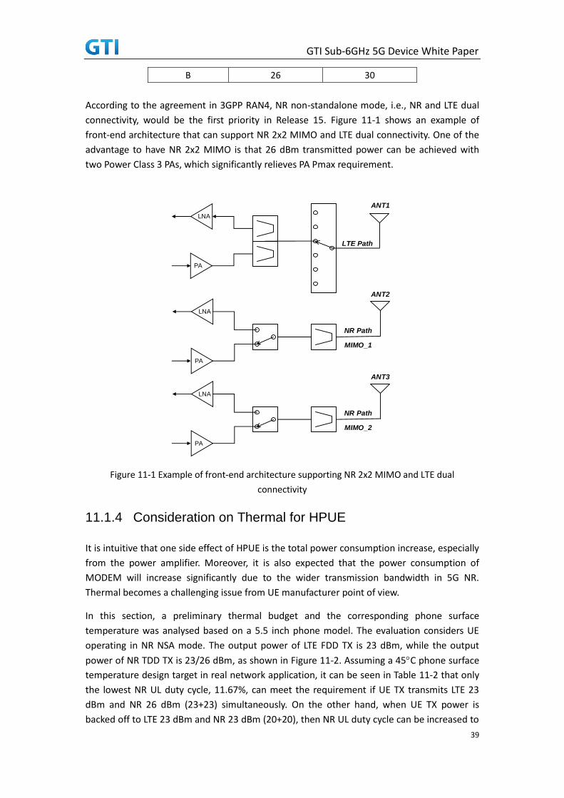
GTI Sub-6GHz 5G Device White Paper
39
B 26 30
According to the agreement in 3GPP RAN4, NR non-standalone mode, i.e., NR and LTE dual
connectivity, would be the first priority in Release 15. Figure 11-1 shows an example of
front-end architecture that can support NR 2x2 MIMO and LTE dual connectivity. One of the
advantage to have NR 2x2 MIMO is that 26 dBm transmitted power can be achieved with
two Power Class 3 PAs, which significantly relieves PA Pmax requirement.
Figure 11-1 Example of front-end architecture supporting NR 2x2 MIMO and LTE dual
connectivity
11.1.4 Consideration on Thermal for HPUE
It is intuitive that one side effect of HPUE is the total power consumption increase, especially
from the power amplifier. Moreover, it is also expected that the power consumption of
MODEM will increase significantly due to the wider transmission bandwidth in 5G NR.
Thermal becomes a challenging issue from UE manufacturer point of view.
In this section, a preliminary thermal budget and the corresponding phone surface
temperature was analysed based on a 5.5 inch phone model. The evaluation considers UE
operating in NR NSA mode. The output power of LTE FDD TX is 23 dBm, while the output
power of NR TDD TX is 23/26 dBm, as shown in Figure 11-2. Assuming a 45C phone surface
temperature design target in real network application, it can be seen in Table 11-2 that only
the lowest NR UL duty cycle, 11.67%, can meet the requirement if UE TX transmits LTE 23
dBm and NR 26 dBm (23+23) simultaneously. On the other hand, when UE TX power is
backed off to LTE 23 dBm and NR 23 dBm (20+20), then NR UL duty cycle can be increased to
LTE Path
PA
LNA
NR Path
PA
LNA
NR Path
PA
LNA
MIMO_1
MIMO_2
ANT1
ANT2
ANT3

GTI Sub-6GHz 5G Device White Paper
40
31.67% as shown in Table 11-3. According to the analysis, it seems that total TX transmitted
power of 26 dBm is more feasible for implementation. Another viewpoint is that the chance
to continuously transmit maximum output power for a long period for an UE should be low
in real network. Therefore, the data in Table and Table could be considered as worst case
and define a relaxed target of 52C phone surface temperature. Then the applicable NR UL
duty cycle can be further improved.
(a) (b)
Figure 11-2 (a) Total transmitted power 27.8 dBm (LTE 23 dBm + NR 26 dBm) (b) Total
transmitted power 26 dBm (LTE 23 dBm + NR 23 dBm)
Table11-2 LTE FDD (23 dBm) + NR TDD 2x2 MIMO (23 + 23 dBm)
Table 11-3 LTE FDD (23 dBm) + NR TDD 2x2 MIMO (20 + 20 dBm)
11.1.5 Consideration on SAR for HPUE
Due to the higher transmitted power than nominal Power Class 3 UE, SAR evaluation for NR
HPUE is quite critical. In a similar fashion, UE with transmitted power of LTE FDD 23 dBm and
NR TDD 26 dBm (63.33% UL duty cycle) is treated as a baseline. Please be noted that WiFi TX
is also considered in this analysis. The results in Table 11-4 compare the SAR value varying
with different NR UL duty cycle. The duty cycle has to be lower than 31.67% in order to pass
4G
LTE
5G
NR
5G
NR
23 dBm 23 dBm 23 dBm
4G
LTE
5G
NR
5G
NR
23 dBm 20 dBm 20 dBm
63.33 % 53.33 % 43.33 % 31.67 % 23.33 % 21.67 % 11.67 %
Phone Surface
Temperature (C)61.5 57.7 53.9 49.5 46.3 45.7 41.9
NR UL Duty Cycle (Re-use LTE TDD Configuration)LTE FDD 23 dBm
NR TDD 23+23 dBm
63.33 % 53.33 % 43.33 % 31.67 % 23.33 % 21.67 % 11.67 %
Phone Surface
Temperature (C)52.7 50.2 47.8 45.0 43.0 42.6 40.2
NR UL Duty Cycle (Re-use LTE TDD Configuration)LTE FDD 23 dBm
NR TDD 20+20 dBm

GTI Sub-6GHz 5G Device White Paper
41
the SAR limit, 2 mW/10g. In summary, a total TX transmitted power of 26 dBm is more
practical in terms of SAR. Otherwise, the UL duty cycle would be quite limited.
Table 11-4 Body SAR Analysis – LTE FDD (23 dBm) + NR TDD 2x2 MIMO (23 + 23 dBm) + WiFi
11.2 In-Device Interference
There are two basic deployment policies for 5G network depending on the preferences of
each operator: standalone deployment and non-standalone deployment.
For standalone deployment, the NR system can work independently with LTE. Thus a single
connectivity with NR network is the basic operation for the UE. In this case, single UL
transmission mode is sufficient as baseline.
To further enhance the standalone deployment, there may be various ways for different
targets, e.g.:
• Throughput enhancement: Carrier aggregation of NR-NR can be used to boost user
data rate.
• Coverage enhancement: SUL (Supplementary Uplink) is using a lower-frequency
carrier for NR UL transmission in addition to NR’s dedicated UL carrier. Due to the
lower frequency, the UL coverage can be significantly improved by transmission on
SUL.
For the above enhancements, UE may support simultaneous transmission of more than one
UL in different bands, which may potentially lead to in-device interference.
For non-standalone deployment, UE should support the dual-connectivity of LTE and NR,
where LTE carrier is always the anchor carrier. In this case, UE may also encounter the
in-device interference issue.
In summary, except the standalone NR operation with one UL band, UE may suffer from
in-device interference due to simultaneous UL transmissions in the non-standalone
deployment and some enhancements of standalone deployment.
There are three different types of in-device interference due to simultaneous UL
transmission over different bands:
Total SAR
(mW/10g)
SAR limit
(mW/10g)
NR UL
Duty Cycle
Body SAR 2.841 2 63.33 %
Body SAR 2.592 2 53.33 %
Body SAR 2.342 2 43.33 %
Body SAR 2.051 2 31.67 %
Body SAR 1.843 2 23.33 %
Body SAR 1.802 2 21.67 %
Body SAR 1.552 2 11.67 %

GTI Sub-6GHz 5G Device White Paper
42
• Interference from Harmonic
This kind of interference comes from the harmonic of lower- frequency UL signals to
the higher- frequency DL signals when the harmonic of UL frequency falls into the DL
frequency. Figure 11-3 shows the case with LTE on a lower- frequency carrier and NR
on a higher- frequency carrier. One example is that when a UE is simultaneously
transmitting on B3 (LTE) and receiving on NR sub-6G band B42 (3.4G~3.6G),
interference from H2 of B3 will fall into NR receiver.
LTE NR sub 6G
LTEUL
LTEDL
NRDL
Harmonic from LTE UL
interfere NR DL
Figure 11-3 Illustration of interference from Harmonic
• Interference from Harmonic mixing
This kind of interference comes from higher frequency UL signals to the lower-
frequency DL signals when the higher frequency is multiple of the lower frequency.
Figure 11-4 shows the case with LTE on a lower- frequency carrier and NR on a
higher-frequency carrier. One example is that when a UE is simultaneously
transmitting on 3.3G~4.2G and receiving on LTE B26, interference from UL will fall into
LTE B26 receiver and be demoded by receiver which causes sensitivity degradation.
LTE NR sub 6G
LTEDL
NRUL
Harm
onic m
ixing f
rom
NR UL i
nterfe
re LT
E DL
Figure 11-4 Illustration of interference from Harmonic mixing

GTI Sub-6GHz 5G Device White Paper
43
To address the interference from Harmonic or Harmonic mixing, the main solution is
based on the transmission coordination between UL and DL transmission. Two
different approaches have been identified as the solutions:
- TDM
- FDM
It means NW can schedule the DL and UL to avoid the interference. However, these
solutions will require the LTE NW and NR NW to share/exchange information, which
may lead to some potential challenges in the multi-vendor deployment scenarios.
• Interference from Intermodulation (IMD)
This kind of interference comes from the intermodulation (IMD) product between
lower-frequency and higher-frequency UL carriers which may fall into the DL carrier.
Figure 11-5 shows the case with LTE on a lower- frequency carrier and NR on a higher-
frequency carrier. One example is that when a UE is transmitting simultaneously on B3
(LTE) and NR sub-6G band (3.3G~4.2G), interference of IM2/IM4/IM5 will fall into B1
LTE receiver.
LTE NR sub 6G
NRUL
LTEUL
LTEDL
IM from NR-LTE UL interfere LTE DL
Figure 11-5 Illustration of interference from IMD
To address the IMD issues, there are some potential ways
- Spectrum allocation
- Single UL transmission
However, spectrum allocation is not always useful due to too many limitations. Thus single
UL transmission has been agreed as an solution in 3GPP. Since the IMD interference is highly
related to the band combinations, UE may support simultaneous UL transmissions for some
band combinations while can only support single UL transmission for other band
combinations. To facilitate NW’s scheduling, UE can report its capability whether or not
support simultaneous UL transmissions based on the band-combination basis, and NW
decide the configuration/scheduling based on UE’s capability report.

GTI Sub-6GHz 5G Device White Paper
44
11.3 SUL
High frequency band provides massive resource for NR deployments. However, high
frequency leads to larger pathloss and smaller coverage. For NR DL, there may be several
alternatives to improve the coverage, e.g., larger base station transmit power, massive MIMO.
In contrast, UL coverage will be more serious due to the limited transmit power of UE and
limited number of transmit antennas. Thus there will be an imbalance between DL and UL
coverage.
In order to improve the UL coverage, a lower-frequency carrier can be used for NR UL
transmission in addition to NR dedicated UL carrier, where the lower-frequency carrier is a
supplementary uplink (SUL). Some typical use cases are as follows:
• For a cell-center UE, NW can configure SUL for higher UL throughput.
• For a cell-edge UE, NW can configure SUL for UL coverage improvement when the NR
dedicated UL carrier is unavailable.
A typical deployment is that NR carrier is on 3.5GHz and SUL is on 1.8GHz, where DL and UL
are expected to achieve comparable coverage.
In addition to data transmission, SUL can be used for initial access. UE can choose SUL or NR
dedicated UL to access the network based on its measurement and NW’s configuration.
To effectively support SUL operations, there will be more requirements for UE
implementation, e.g.:
• Different RF chains: As the main motivation of SUL is to improve UL coverage, the SUL
and NR dedicated DL/UL are usually in different frequency bands. Depending on the
specific band combination, UE may need two different RF chains, each of which is for
one frequency band.
• Synchronization of two UL chains: The PHY scheduling depends on various types of
timing, thereby requiring synchronization of two UL carriers/chains.
• Simultaneous UL transmission: one is SUL and the other is dedicated UL.
• Dealing with different numerologies for different UL transmissions.
11.4 LTE and 5G NR RF path co-banding
Spectrum allocation in sub-6 GHz, in general, is very scarce and possibly requires
co-existence of multiple RAT within the same / adjacent block of channels. In this section,
support for LTE and NR within the same band or block of spectrum is discussed since it is
expected to be legitimate scenario. For example, Band 41, 42/43 with such large spectrum
block can be utilized for LTE and NR in the same band. This requires tight co-operation and
interference mitigation amongst LTE and NR. Besides operator sharing band for LTE and NR,
different operator may have deployed different RAT within a given band or block of spectrum,
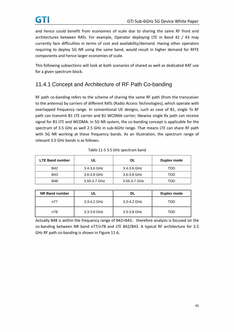
GTI Sub-6GHz 5G Device White Paper
45
and hence could benefit from economies of scale due to sharing the same RF front end
architectures between RATs. For example, Operator deploying LTE in Band 42 / 43 may
currently face difficulties in terms of cost and availability/demand. Having other operators
requiring to deploy 5G NR using the same band, would result in higher demand for RFFE
components and hence larger economies of scale.
This following subsections will look at both scenarios of shared as well as dedicated RAT use
for a given spectrum block.
11.4.1 Concept and Architecture of RF Path Co-banding
RF path co-banding refers to the scheme of sharing the same RF path (from the transceiver
to the antenna) by carriers of different RATs (Radio Access Technologies), which operate with
overlapped frequency range. In conventional UE designs, such as case of B1, single Tx RF
path can transmit B1 LTE carrier and B1 WCDMA carrier; likewise single Rx path can receive
signal for B1 LTE and WCDMA. In 5G NR system, the co-banding concept is applicable for the
spectrum of 3.5 GHz as well 2.5 GHz in sub-6GHz range. That means LTE can share RF path
with 5G NR working at these frequency bands. As an illustration, the spectrum range of
relevant 3.5 GHz bands is as follows:
Table 11-5 3.5 GHz spectrum band
LTE Band number UL DL Duplex mode
B42 3.4-3.6 GHz 3.4-3.6 GHz TDD
B43 3.6-3.8 GHz 3.6-3.8 GHz TDD
B48 3.55-3.7 GHz 3.55-3.7 GHz TDD
NR Band number UL DL Duplex mode
n77 3.3-4.2 GHz 3.3-4.2 GHz TDD
n78 3.3-3.8 GHz 3.3-3.8 GHz TDD
Actually B48 is within the frequency range of B42+B43,therefore analysis is focused on the
co-banding between NR band n77/n78 and LTE B42/B43. A typical RF architecture for 3.5
GHz RF path co-banding is shown in Figure 11-6.

GTI Sub-6GHz 5G Device White Paper
46
3.5GHz LTE
3.5GHz PA 3.5GHz LNA
LTE MODEM NR MODEM
Antenna switch module
ANT
3.5GHz TX
FILTER
3.5GHz RX
FILTER
LTE/NR Transceiver
3.5GHz LTE/NR Co-banding
3.5GHz LTE/NR Co-banding
3.5GHz LTE/NR Co-banding
3.5GHz NR
Figure 11-6 3.5GHz typical RF architecture
As shown in Figure 11-6, 4G LTE and 5G NR have separate modem. The co-banding path
starts at the transceiver, through PA/LNA and the same filter/ switch/antenna. The advantage
of RF path co-banding is obvious that the cost and PCB area are saved by sharing the same
components, and the UE design can leverage the experience of 4G LTE and 3G WCDMA
co-banding. On the other hand, there are plenty of challenges when migrating the design
considerations from LTE/WCDMA co-banding to the LTE/NR co-banding, for example the
increased bandwidth of NR compared to the LTE, the PAPR (Peak to Average Power Ratio)
difference of uplink signal, etc., as analyzed in following sections.
11.4.2 System-level Challenges
At system level, the main challenges of LTE/NR co-banding come from the 5G NR
requirements. The differences between 5G NR and 4G LTE include:
Compared to the LTE system with a maximum channel bandwidth of 20 MHz, 5G NR has
a higher maximum channel bandwidth of up to 100 MHz;
Compared to the LTE system with the uplink carrier of DFT-SC-OFDM, 5G NR is to
support both CP-OFDM and DFT-S-OFDM, and there will be a PAPR shift for CP-OFDM
modulation on the baseline of LTE DFT-S-OFDM;
Compared to the LTE system with the maximum RF output power of 23dBm, 5G NR is
supposed to output a power up to 26dBm of power class 2.
Therefore the RF-path co-banding design needs to utilize a common path to reach different
targets of LTE and 5G NR. A systematic approach is necessary to decompose the RF chain and
analyze the impact to key components. The main considerations are presented next.

GTI Sub-6GHz 5G Device White Paper
47
Transceiver
A key challenge is to support the bandwidth up to 100 MHz with a single carrier. If the
bandwidth of 100 MHz for a NR carrier can be supported, then the bandwidth of 20
MHz for LTE should not be the bottleneck. Furthermore, special attention should be
paid to Tx noise/emission and Rx out of band blocking performance, with broadband
filter configured for Tx and Rx.
Power Amplifier (PA)
Both the channel bandwidth and the wide frequency range will be the challenge. For
example, for NR band n77 ‘s frequency range 3.3-4.2 GHz, it is quite difficult for a single
PA to cover such a wide bandwidth of 900 MHz, compared to the bandwidth of 200 MHz
in LTE B42 or B43. A suggested way is to split the full frequency range into two parts,
and apply two PAs to meet the requirements, but this needs more investigations. About
the single channel bandwidth, 100 MHz per NR channel requires much wider effective
bandwidth possessed by biasing and supply feeding circuits, compared to 20 MHz in LTE
case. That also necessitates schemes to mitigate the memory effect and ensure the
linearity performance.
The exact maximum output power of 5G NR is to be determined by standardization
bodies. Even if targeting at the same level as LTE power class, generating enough output
power for such wide NR channel bandwidth is not easy task for the component vendors.
Aforementioned 5G NR uplink will use the waveform of CP-OFDM, which has a much
higher PAPR than SC-FDMA of LTE, necessitating higher peak power capability of PA. If
the PA is specified as same power class for NR and LTE, its power added efficiency (PAE)
in LTE mode will normally degrade due to operating away from relevant optimum
output power level.
Filter
In the co-banding scenario of 3.5 GHz LTE/NR, the total bandwidth of 900 MHz of n77 is
problematic for conventional SAW/BAW filter design. Ceramic technology based filter is
considered but the performance of insertion loss and out of band attenuation needs to
be balanced. For a single carrier of 100 MHz, the challenge comes from the group delay
parameter which typically degrades the uplink EVM performance.
Low Noise Amplifier (LNA)
The main concern of LNA for 3.5 GHz LTE/NR co-banding is its gain and noise figure
performance, due to the wide frequency range coverage. LNA commonly gets integrated
into the transceiver, so this aspect shall be considered into the transceiver design as
well.
Antenna switch module
The power handling of ASM should cover the peak power of NR, which would increase
the area, cost and design complexity of the switches. On the other hand, the switching
speed need to be faster than LTE to satisfy the NR system requirements.

GTI Sub-6GHz 5G Device White Paper
48
Antenna design considerations for LTE/NR co-banding
NR band n77’s bandwidth of 900 MHz is significantly wider and more challenging than
n78’s bandwidth of 500 MHz; n77 deserves more attention than n78 accordingly. For NR
band n77, its relative bandwidth percentage is 24.0%, which is close to the relative
bandwidth percentage of 23.7% for the existing and common LTE mid bands ranging
from 1710 MHz to 2170 MHz. Therefore, similarly, it should be achievable to enable
efficient radiation for n77 by the solution of a single antenna. Besides, two separate
antennas covering 3.3-3.8 GHz for n78 and 3.8-4.2 GHz for the rest of n77 respectively
connected to the ASM directly and individually can be also the option to meet n77’s
wide-band requirement with the decent antenna efficiencies. However, when the
architecture of two separate antennas is employed, the isolation between the two
antennas should hence be taken into design consideration and overall performance
balance. Last, no matter the architecture of the single antenna or two separate
antennas is used, the risk of antenna isolation should not be ignored compared to the
existing LTE architecture and placement because more antennas will be requested by
sub-6 GHz 5G communication systems.
11.4.3 Way Forward on standalone support
The RF path co-banding of LTE/NR can better utilize the spectrum allocated globally and
reuse the overall UE system architecture for simplification. As stated, there are challenges
due to the new requirements of NR quite different from LTE. It will be valuable to investigate
more into the system level analysis, component level design and practical implementation so
as to achieve good RF performance with the co-banding of LTE/NR.
11.4.4 Co-banding with simultaneous operation
So far, the previous subsections focused on non-shared use of RF front end for a given
spectrum block/band. Another important scenario is support for simultaneous operation of
multi-RAT within a given block of spectrum. From a device architecture point of view, it may
be possible to re-use / share the same RF front end architecture components / transceivers
across different RATs within shared spectrum. However, there may be
co-existence/interference concerns if multiple RAT are not synchronized in terms of DL / UL
operation. This would require the device to adhere to in-band RF performance specifications
as defined by 3GPP, while maintaining good spectral efficiency. Some of the key
requirements are as follows:
In-band Emission (NR & LTE): Meet SEM requirements. MPR/AMPR values yet to be defined.
Adjacent channel selectivity (NR & LTE): 27 dB (LTE) and 33dB (NR)
ACLR (NR & LTE): 31dB for 20MHz channels. FFS for other CBWs
Guard band requirement (NR & LTE): FFS in 3GPP
In-band blocking: FFS in 3GPP

GTI Sub-6GHz 5G Device White Paper
49
In-channel selectivity: FFS in 3GPP
Beside these adjacent channel requirements, co-channel deployment of LTE and NR may be
possible. This would require a use of TDM approach between LTE and NR (using MBSFN
subframes). However, this may have impact to overall system efficiency and hence, it is not
recommended to use such deployment scenario.
12 Demodulation Performance
In some countries, several vehicles move with the speed over 300km/h, e.g., Japan Tohoku
Shinkansen (320km/h), German ICE (330km/h), AGV Italo (400km/h), and Shanghai Maglev
(430km/h). With the increase of high speed moving environment, the demand of using
mobiles is growing larger. Therefore, it is important to guarantee the performance under the
high speed scenarios.
High speed leads to high Doppler Shift, which may significantly decrease the demodulation
performance of UE and affect user experience in the high-speed train scenario. For 5G, the
UEs’ demodulation performance should meet the relevant requirements of 3GPP in the
scenarios where the mobility speed is up to 500km/h. In Table 12-1, we calculate the
Doppler shift under different speed and frequency. For 3.5GHz, the scope of Doppler Shift is
up to ±1620 Hz with 500 km/h mobility speed.
Table 12-1 Doppler shift under different speed and frequency
In order to have better network performance, dedicated network is deployed along the high
speed railway. To avoid interference, separate carriers are utilized for dedicated network and
public network. To avoid frequent handover, cell combination is applied: multiple RRHs are
connected to one BBU with fiber. The coverage of a single cell can be extended significantly,
and no handover is necessary within several RRUs belonging to the same BBU. Figure
shows the dedicated high speed train scenario in our network. [14]
Speed (km/h) Doppler shift (Hz)
1.9GHz 2.6GHz 3.5GHz
100 176 241 324
200 352 481 648
300 528 722 972
350 616 843 1134
400 704 963 1296
450 792 1083 1458
500 880 1204 1620

GTI Sub-6GHz 5G Device White Paper
50
Figure 12-1 Dedicated high speed train scenario
The above high speed scenario has multiple taps. The UEs’ demodulation performance
should meet the needs of multi-path signals with opposite Doppler Shifts.
As a summary, high speed train scenario is a changeling scenario for demodulation. However,
through carefully designed reference signal and receiver algorithm, most of the negative
impact can be mitigated. More future studies are needed for NR demodulation.
13 Power Consumption
13.1 Introduction
The main topic of this chapter is the changes that we might expect to see in the power
consumption of the NR modem compared to its predecessors. In the UE as a whole,
significant power may also be consumed in the display and the applications processor, but
these will not be considered here, other than to mention that higher data rates in the
modem are likely to be accompanied in the UE by higher resolution displays and graphics
engines driven by faster applications, and these will also have an impact on UE power
consumption.
The modem becomes a significant contributor to the power requirement once connectivity is
involved, and can be the dominant user of power when data rates are very high, or when
channel conditions are poor. The challenge facing NR is not simply to deliver higher
instantaneous data rates, but to ensure that data transfer happens in an energy efficient way
whether the average data rate is very high or very low. In this section we will be taking a
closer look at the factors affecting the power requirements of the NR modem in different use
cases, and some of the ways in which the UE and the network can help each other to ensure
that the energy in the UE battery is used as efficiently as possible.

GTI Sub-6GHz 5G Device White Paper
51
13.2 Key scenarios and performance metrics
The power consumption in a UE depends on a number of variable factors, among them the
radio environment between the UE and the gNB, user data throughput and usage patterns,
quality of service requirements, network coverage provision and user mobility. A user on the
edge of a cell will inevitably experience slower throughput and higher power consumption
than one who is near a gNB and has a good multipath environment. For a better
understanding of UE power consumption patterns it is helpful to standardise environmental
factors as far as possible and look at a few simple scenarios.
13.2.1 A figure of merit (FOM) for power consumption
The simplest case to consider is that of maximum power consumption, which occurs when
the modem is receiving and transmitting data at the maximum rate, with transmit power set
to the maximum level. If the transmit power is kept constant, a reduction in uplink data rate
will not have a significant effect on power demand, as the power is simply redistributed
among fewer bits. Unless the UE is sufficiently close to the gNB that the transmit power level
can be reduced, this configuration represents the most energy-efficient mode of transferring
data, and dividing the total power drawn from the battery by the UE downlink data rate gives
a representative figure of merit, which for current LTE UEs might be of the order of 1nJ-10nJ/
received bit [13]. The precise figure would vary with UE category and model - it could be
higher than the stated range, but the power required from the battery for uplink
transmission alone means that it is unlikely to fall below 2nJ/bit for an LTE handset. It should
be noted that even at 1nJ/bit, an NR UE operating at 4Gbps would have a power
consumption well in excess of 4W, after adding in the power for the display and applications
processor. An average UE battery today has a capacity of around 12Wh, so this rather
extreme use case would only allow a maximum of 3 hours of continuous use before
recharging.
But most users who do not have exclusive occupancy of the cell will only experience the
maximum throughput in short bursts – if the throughput reduces to 200Mbps, can we expect
a 95% reduction in UE power consumption? A 200Mbps connection at 200mW would allow
nearly 60 hours of data transfer (up to 40Tbytes) on a 3000mAh battery before recharging,
which most of today’s users would find very attractive.
13.2.2 The power vs latency trade-off
Sadly the answer to the question in the previous paragraph is no – there are some
unavoidable energy costs in the UE that worsen the figure of merit as the data rate falls - but
using some of the features of NR with cooperation between the UE and the network we
could come close in some cases. The main reason for reduced energy efficiency of data
transfer at lower rates is that the UE does not know when incoming data will be arriving, so it
needs to monitor the control channel frequently to find out when data is present. It also has
to receive the data channel at full bandwidth for at least as long as it takes to decode the

GTI Sub-6GHz 5G Device White Paper
52
control channel, in case the control channel carries a data assignment. If there is a low
latency requirement (sub-1ms), it might be necessary do this in every TTI, which is
detrimental to power consumption when data rates are low.
In LTE, the downlink assignment has always been sent in the same TTI as the associated data.
NR introduces the possibility of cross-slot scheduling, where the assignment can refer to the
next TTI, or a later one [14]. This can help the UE to save power in two ways – firstly, in
control-only periods, it can turn off its receivers as soon as the control channel symbols have
been captured, and secondly, the control channel can be transmitted over a reduced
bandwidth, allowing the UE to sample and process at a reduced rate for those TTIs in which
the data channel is not needed. The combination of these two features means that receiving
the control channel can be much more power efficient, and full bandwidth reception and
processing is only needed when there is actually data present. The penalty is an increase in
latency of at least one TTI, but since NR can accommodate shorter TTIs than LTE, sub-1ms
latency is still achievable. This is illustrated below in Figure , the upper graph showing the UE
power profile with same-slot scheduling and the lower graph showing the savings that result
when cross-slot scheduling is enabled.
Figure 13-1 Power saving from Cross-slot scheduling
Where the latency requirement can be relaxed, further power savings can be made by
implementing a DRX cycle. This will reduce the active duty cycle for control channel-only
monitoring, and if cross-slot scheduling is active then data channel reception is only needed
when UE data is present. With this configuration the modem might spend 90% of its time in
a low power sleep state, with corresponding power savings, but the penalty would be
substantially increased latency – perhaps several 10’s of milliseconds. For many popular
applications (social media, YouTube, file transfer….) strict low latency is not a user
requirement, and most users would find this a price worth paying for increased battery life.
For other applications, practical considerations sometimes impose a lower limit on the
latency that can be tolerated. For example, in high quality audio or video telephony, round
trip delays of more than 100ms or timing offsets between the audio and video streams can
become very noticeable, and since speech is processed in frames of 20ms duration a latency

GTI Sub-6GHz 5G Device White Paper
53
of one or two speech frames is significant. Semi-persistent scheduling can reduce the level of
signaling required, but even so it would be necessary to process the control channel and data
channel at least once every 20 or 40 ms.
13.2.3 Achieving power efficient VoNR and ViNR
Today’s UEs (2G, 3G or 4G) claim talk times of up to 30 hours for voice calls, and setting this
against the typical battery capacity this equates to an average power consumption of around
300-400mW. When moving from LTE to NR it is important to remember that the energy cost
of processing one TTI at 100MHz will be higher than the cost of processing a TTI of the same
duration at 20MHz, even though the energy per bit will be lower. Shorter NR TTIs will help in
this respect, but the key to low power consumption for NR voice will be to keep the data that
the UE has to process for a voice call to a minimum.
If power consumption for VoNR (Voice/video over NR) is to be competitive with VoLTE and
older technologies, bandwidth adaptation will be highly desirable to make the best use of
the processing resources in the UE. If the network can deliver 4Gbps, then a single 250us TTI
can deliver 1 Mbit of data, and if that happens once every 20ms (1.25% of network capacity),
that is sufficient to support a high definition video connection. If all that is needed is a 250
bit speech frame, it makes no sense for the UE to receive and process the full bandwidth
simply to discard 99.9% of the sampled data that is processed. It would be more power
efficient to receive a narrower bandwidth containing the required resource blocks and
sample and process these at a lower rate to save power.
13.2.4 Spectrum usage for NR
Fortunately for the first generation of NR UEs, most of the high bandwidth spectrum under
6GHz is found in TDD-only bands. This results in a tradeoff between uplink and downlink
data rates, but it also means that receive and transmit will not both occur at the same time,
reducing both the peak and the average power requirement in the UE. Even so, a UE
operating at maximum throughput for prolonged periods (for example, when transferring
large data files) may still experience a large increase in its internal temperature, and would
then need to negotiate with the network to reduce its data throughput temporarily to allow
its temperature to stabilise at an appropriate level.
These examples illustrate how some of the key features of NR can be used to adapt UE
behavior so that power efficiency can be optimised to deal with the traffic that is present.
Cross-slot scheduling allows more efficient use of the physical receive and transmit resources
in the UE. Bandwidth adaptation means that irrelevant resource blocks can be excluded from
the sampling process, resulting in a lower processing load, and DRX allows appropriate
tradeoffs to be made between power consumption and latency.
In practice a single UE can carry several different types of traffic concurrently, and a fully
optimised solution may require unacceptably high levels of signaling, or be beyond the
capabilities of existing scheduling algorithms. The improvements that have already been

GTI Sub-6GHz 5G Device White Paper
54
made for NR include many of the building blocks that are needed to improve power
efficiency - it will be up to network operators and UE manufacturers to use them wisely.
13.3 Power scaling from LTE to NR
The first mainstream NR UEs are likely to offer peak data rates of around 2Gbps downlink and
1Gbps uplink, with premium devices offering maybe 5Gbps downlink and 1.5Gbps uplink.
Depending on the network rollout, these may be either non-standalone devices, using the LTE
network as an anchor for initial access and mobility, but supplemented by one or more NR
carriers for high data rates and low latency, or standalone devices which use only NR carriers.
13.3.1 Example power breakdown for an LTE UE
Figure 13-2 below shows a typical power breakdown for a Cat4 LTE UE in 2013 [11], with the LTE
modem accounting for approximately 2.7W of the total. Since that time, smaller process
geometries and design improvements have resulted in power savings in the modem, but over the
same period higher throughput from carrier aggregation has increased the processing load,
cancelling out many of the savings as the price for increased capability. Modem power
consumption can still reach 3W or more (3nJ/bit at peak LTE data rates for the previously
discussed figure of merit).
Figure 13-2 LTE UE power consumption
It is therefore of interest to consider how the modem power might scale with the move to NR
and a 4 to 5 times increase in data rates, using the model described in the previous section.
13.3.2 RF front end
From 错误!未找到引用源。, 160mW of transmit power (22dBm) requires 1.35W from the
battery, so for a 23dBm average we would need approximately 1.7W of battery power.
GTI Sub-6GHz 5G Device White Paper
55
13.3.3 Transceiver subsystem
The transceiver for a non-standalone NR UE requires at least two LTE receivers (2x2 MIMO)
and one transmitter. Additional LTE carriers may be supported for cases where there is no NR
coverage, but in NR mode the total transceiver power will be minimised if the other active
receivers and transmitters are assigned to NR carriers.
200MHz of NR bandwidth at 4x4 DL MIMO is needed for 4Gbps throughput – with 15 kHz
subcarrier spacing the widest supported carrier is 50MHz and so 4 carriers would be needed,
implying 16 receivers, and 4 synthesisers in receive mode, if the carriers are noncontiguous.
With 30 or 60 kHz subcarrier spacing 100MHz carriers can be supported, meaning that only 8
receivers and 2 synthesisers would be needed. Achieving the required antenna isolation for
MIMO operation at sub-6GHz frequencies may limit the number of independent antennas
that can be offered in small-footprint devices. This in turn would restrict the total number of
transmitters/receivers that could be supported.
The 150mW receiver power from Figure represents the power for 2 receivers and one
synthesiser, together with the ADC and baseband interface. 16 receivers and 8 synthesisers
(1.2W) is an overestimate of the power for the 15 kHz case (only 4 synthesisers are needed).
If we allow for improvements in receiver efficiency since 2013, we might expect a receive
mode power of around 800mW for the 15 kHz case and 400mW for the 30 and 60 kHz case.
Transmit mode power is harder to extract from these figures, but we need the same number
of synthesisers in transmit mode as we do in receive mode, and 2x2 MIMO means we only
need half the number of transmitters as receivers. For maximum power in the PA the power
in a transmitter is likely to be higher than a receiver, so the corresponding figures in transmit
mode might be 600mW for the 15kHz case and 300mW for the 30 and 60kHz cases.
13.3.4 Baseband processing
From 错误!未找到引用源。, baseband processing accounts for 1.1W of power consumption
in the 2013 handset, with most of the complexity residing in the downlink. A Cat4 LTE UE has
a downlink throughput of 150Mbps – a straightforward scaling with data rate might lead us
to expect that at 4Gbps, the modem power would increase to almost 30W.
However, the baseband for the UE measured in 2013 came from a 28nm silicon process, and
NR UEs will be using smaller and more power-efficient geometries – a factor of 4 reduction
from geometry scaling (not unrealistic) would bring this down to a slightly more manageable
7.5W. Further gains can be made from architectural improvements using more efficient
processors and hardware accelerators.
In addition to this, the lower complexity of NR decoding should lead to substantial power
reductions in downlink processing [16], and may bring the 1nJ/bit barrier within reach.

GTI Sub-6GHz 5G Device White Paper
56
13.4 Managing UE power efficiently
The simple power model presented here suggests that NR UE power consumption at peak
throughput may be higher than for an LTE UE offering lower throughput, but the energy per
bit at maximum performance will be significantly better. The key to competitive NR UE
performance will be how well the power consumption scales with data rate at lower
throughputs. Most users do not currently require sustained high throughput for long periods,
and experience with LTE devices indicates that for many typical use cases a significant
proportion of UE power is spent monitoring the control channel during periods when user
data is absent [18].
A UE that uses power efficiently needs to turn on receivers and transmitters only when
necessary, and to discard any downlink data that is not intended for it at the earliest
opportunity.
13.4.1 Overtemperature protection
With increasing peak data rates, UE overheating remains a possibility. A UE must have
options to reduce its power consumption in a controlled manner without terminating
connectivity if it experiences overtemperature as a result of prolonged high throughput.
13.4.2 Bandwidth adaptation
The sampling rate in the analog-digital interface has a direct effect on power consumption.
Bandwidth adaptation can be used to confine the control channel for a specific UE or group
of UEs to a narrow bandwidth which can be received with minimum resources at a lower
sample rate to reduce the cost of control channel-only cycles where no data is present.
13.4.3 Cross-slot scheduling
Cross-slot scheduling allows similar savings can be made on the data channel, with receive
and transmit resources only being enabled for the resource blocks that have been allocated.
This can be particularly advantageous for data traffic consisting mainly of small packets,
where receiving and processing over the full channel bandwidth may require
disproportionate levels of power. The network can assist the UE in this respect by scheduling
the UE resource block allocation appropriately, confining it to narrow bandwidths wherever
possible.
13.4.4 Power vs data rate
With these features in place, power consumption for the UE then consists of two main
components. The first is a baseline power level for control channel monitoring, which can be
further reduced if the network sets a DRX cycle which is compatible with the latency
requirements of the traffic. The second is a data component which is much more closely
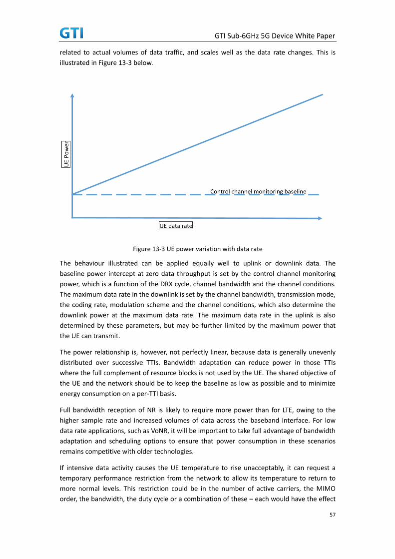
GTI Sub-6GHz 5G Device White Paper
57
related to actual volumes of data traffic, and scales well as the data rate changes. This is
illustrated in Figure 13-3 below.
Figure 13-3 UE power variation with data rate
The behaviour illustrated can be applied equally well to uplink or downlink data. The
baseline power intercept at zero data throughput is set by the control channel monitoring
power, which is a function of the DRX cycle, channel bandwidth and the channel conditions.
The maximum data rate in the downlink is set by the channel bandwidth, transmission mode,
the coding rate, modulation scheme and the channel conditions, which also determine the
downlink power at the maximum data rate. The maximum data rate in the uplink is also
determined by these parameters, but may be further limited by the maximum power that
the UE can transmit.
The power relationship is, however, not perfectly linear, because data is generally unevenly
distributed over successive TTIs. Bandwidth adaptation can reduce power in those TTIs
where the full complement of resource blocks is not used by the UE. The shared objective of
the UE and the network should be to keep the baseline as low as possible and to minimize
energy consumption on a per-TTI basis.
Full bandwidth reception of NR is likely to require more power than for LTE, owing to the
higher sample rate and increased volumes of data across the baseband interface. For low
data rate applications, such as VoNR, it will be important to take full advantage of bandwidth
adaptation and scheduling options to ensure that power consumption in these scenarios
remains competitive with older technologies.
If intensive data activity causes the UE temperature to rise unacceptably, it can request a
temporary performance restriction from the network to allow its temperature to return to
more normal levels. This restriction could be in the number of active carriers, the MIMO
order, the bandwidth, the duty cycle or a combination of these – each would have the effect

GTI Sub-6GHz 5G Device White Paper
58
of reducing either the number of active resources in the transceiver, or the data bandwidth
crossing the baseband interface, leading to a reduction in power consumption.
13.5 Implications for NR UEs
The analysis presented here is approximate, but it still allows us to draw some useful
conclusions. Firstly, it seems likely that, at least for the first generation NR devices, a UE
operating at 4Gbps will require more power from its battery than an LTE UE operating at
1Gbps or below, simply due to the increased processing requirement. However, if the two
devices operate at comparable data rates, the NR UE will require less power, since it will have
fewer receive and transmit resources active for less of the time, and there will be efficiency
gains in the baseband processing.
In principle a standalone UE should consume less power than a non-standalone UE, requiring
fewer receive and transmit resources for equivalent bandwidth. However, if both cases use
an anchor carrier in the lower frequency bands for improved coverage, the anchor
bandwidth would probably be significantly lower than 100MHz whether it was NR or LTE,
and this would tend to reduce any differences.
Silicon processing advances continue to deliver improvements in power consumption, but at
an increasing cost. The power requirement for downlink processing will reduce over time,
although history suggests that future bandwidth increases will continue to present
challenges for battery technology and thermal management in the UE.
Since average transmit power is limited by RF regulations, and the total carrier bandwidth is
increased, there will be less energy per uplink subcarrier in the NR bands than in the LTE
bands. TDD operation in the NR bands will allow the PA to increase its peak power output,
and this may be necessary to maximise the coverage area over which full bandwidth uplink
communication can be sustained. The average power will be kept within limits by adjusting
the TDD duty cycle.
Most of today’s use cases can be accommodated comfortably if the user has reliable access
to a 50Mbps data bandwidth, even allowing for the impact of high definition video on
bandwidth requirements. Users will appreciate the benefits that higher bandwidth can
deliver in terms of response times and file transfer speeds, but the single-user applications
that stretch the capabilities of a multi-gigabit connection are probably still to be written.
Power consumption in NR UEs will need to be competitive for all patterns of traffic from
gigabits per second down to bits per second, and this will require cooperation between
networks and UEs to match UE resource allocation to data traffic patterns in ways that allow
the UE to reduce the data bandwidth that it has to process, and the time for which it is active,
so that it can further optimise its power consumption. This will be particularly important
when competing with established low data rate services such as voice telephony.
Networks that make the best use of the new features that NR offers to optimize UE power
consumption will gain a competitive advantage, benefitting from more satisfied customers
and increased revenues per user.

GTI Sub-6GHz 5G Device White Paper
59
14 Test Requirements
With the implementation of 5G over the next decade, device manufactures will face new
challenges in testing their hardware, software, and end-to-end deployments. 5G technology,
as currently envisioned, is quite different from 4G and will bring together some of the most
challenging aspects of existing test approaches and test equipment. It will also introduce
new challenges, requirements and risks described further here.
14.1 Test areas for 5G sub-6G and challenges
Test solutions must evolve and adapt for 5G, effectively handling the three major use cases
identified by 3GPP. It is obvious that 5G is not going to have a monolithic, one-size-fits-all
deployment, and any test area, equipment and approach must reflect this. There will be very
different requirements with regard to bandwidth, latency, radio characteristics, energy use
and mobility.
14.1.1 Test challenges
Traditional device characterization in lower frequency devices has been limited to narrow
band and Continuous Wave (CW) modes, but now it is expected that wide band modulated
characterization of devices is required to ensure the device technology suitable for the new
5G waveforms. High bandwidth place challenging demands on components such as filters,
mixers, power amplifiers and antennas that are used in mobile devices. To efficiently and
reliably characterize these components, measurement systems must offer wide frequency
coverage, high dynamic range, high output power, signal stability and signal quality with as
little distortion and as few harmonics as possible.
14.1.2 Requirement for test equipment
Technological innovations combined with close and trustworthy customer relationships
requires innovative test and measurement solutions that allow customers to launch their
products more quickly, safely and economically.
Test equipment should be capable to generate and analyze wideband signals. Power
amplifiers are crucial to link performance. By using CW and modulated stimuli to characterize
power amplifiers (PA) in detail, test equipment should efficiently determine amplifier KPIs
such as EVM, AM/AM plus AM/PM conversion and gain compression from a single
measurement.
Besides providing sufficient measurement accuracy, test equipment need to keep the test
cost low enough to meet the demands. Today’s market requires test solutions that address
legacy technologies, while also supporting numerous verification requirements. Controlling
the cost of test is the key attribute.

GTI Sub-6GHz 5G Device White Paper
60
14.2 Device test cycle and test solutions
To develop a new product such as a wireless communication device, it will typically start with
feasibility leading to development and implementation phase to commercial quality which
will be tested against industry standards and specific customer requirements.
Figure 14-1 Stages of Test solutions
The above diagram illustrates the product development stages and the different test
equipment and solutions required for each of the stages.
The initial stages tend to require general purpose test equipment which the test equipment
vendors could develop based on the early of 5G requirements such as waveforms,
modulations, etc. As the development stages progress, the complexity of the test solutions
required would increase. Similar to the device development, the test equipment
development would need to closely follow the development of the technical standards of 5G
by 3GPP. The testing involved will move from basic tests to more focused tests for the
different layers of the protocol.
The entire protocol stack would then be tested in an integrated form which would normally
require industry defined tests, such as conformance tests specified by 3GPP RAN WG5
(RAN5). Test equipment vendors would typically work closely with RAN5 and other industry
bodies such as GCF to provide test solutions to enable device manufacturers and operators
to carry out such tests. In addition, the mobile operators around the world may have
additional tests defined as Carrier Acceptance which they would require the device
manufacturers to run.

GTI Sub-6GHz 5G Device White Paper
61
When the new device development is complete and move into production, specific test
solutions will be required to check the critical parameters and fucntions of the products for
quality assurance purpose.
14.3 Risks
With any new technology, there will be the usual technical risks associated with a new design
and problems encountered during the implementation. There is however some risks which
are unique to the development of 5G NR.
The first major risk for 5G NR is whether the commercial service target will be met with
working solutions. This is largely caused by the very tight timescale for the definition 5G
specifications and the development of new devices following these specifications. For 3G
and LTE, there was a period of about 4-5 years from the development of the 3GPP core
specifications to the general commercial service launch. However, for 5G NR, the current
plan suggests that this period will be reduced to 3 years. It means that the development of
the new specifications and new devices, both user equipment and network equipment, will
have to take place in parallel. The risk is particularly increased with the introduction of
mmWave for the higher frequency bands. It is because mmWave is an entirely new
technology for mass cellular mobile communication.
Many vendors are closely tracking the progress of the 3GPP core specifications in order to
minimize the risks in developing their devices in parallel. Nevertheless, in order to meet the
timescale, there will be a level of speculative development involved in trying to predict what
may or may not be included in the 3GPP standards. The speculative nature means that the
development team must build in flexibility in their design to allow rapid changes to be made
at a later stage.
Another way to mitigate the risks is for the test equipment and the device vendors to work
closely from early stages of the development. They will each independently monitor and
interpret the output of 3GPP from each meeting. When working together, they can compare
the understanding and cross validate with each other in order to have a better chance to
arrive at a common correct interpretation. This will minimize the necessity of rework during
development. It will also ensure a smoother path during the test phase.
The second key risk is the introduction of mmWave in a mass cellular communication
network. mmWave as technology has been used in many high frequency applications such as
satellite and short-range radio communication applications. But it has not been used in a
highly dense and flexible cellular communication application where the geographical
coverage will be wide and user behavior is extremely unpredictable. The industry has been
doing extensive investigations on mmWave in the last few years to characterize it behavior in
a cellular environment. Whilst these investigations are no doubt very valuable to assess the
suitability and the risks, it is simply not possible to cover every eventual use cases involved.
For this and other reasons such as costs of deployment, the initial application for mmWave
operation tend to focus on fixed point-to-point such as home broadband where the
geographical environment can largely be pre-determined.

GTI Sub-6GHz 5G Device White Paper
62
15 Other Aspect
GTI Sub-6GHz 5G Device Whitepaper targets enhanced Mobile Broadband (eMBB) scenario for
Sub-6GHz 5G pre-commercial and commercial products, which discusses Form Factor of 5G
Devcie, Communication Function and Performance requirements and the hot topics of 5G
Devcie Implementation. This document conducted to be the technical references for the
development of chipset/device and the basis for the 5G pre-commercial and commercial
products specs. According to the progress of 3GPP 5G NR standardization and the findings
from the development and trials, there will be more key issues need to be discussed in the
updated version of this Whitepaper in the next step.