gtxraster cad series v9 - gtx corporation gtxraster cad series version 9.0 11 gtxraster tools 11...
TRANSCRIPT

User’s Manual
GTXRaster CAD® Series V9.0
GTX Corporation
Rev 1005
1111
Copyright Notice The information contained in this document is subject to change without notice. If you find any problems in this document, please report them to us in writing. GTX® does not warrant that this document is error-free, and is not liable for errors in this document or for incidental or consequential damages in connection with the furnishing, performance, or use of this document. This document contains proprietary information that is protected by copyright law. All rights are reserved. No part of this document may be photocopied, reproduced, or translated to another language without the prior written consent of GTX. THE SOFTWARE IS PROVIDED “AS-IS” AND WITHOUT ANY WARRANTY OF ANY KIND, EXPRESS, IMPLIED OR OTHERWISE, INCLUDING WITHOUT LIMITATION, ANY WARRANTY OF DESIGN, MERCHANTABILITY OR FITNESS FOR A PARTICULAR PURPOSE OR ARISING FROM A COURSE OF DEALING, USAGE OR TRADE PRACTICE. IN NO EVENT SHALL GTX BE LIABLE FOR ANY ACTUAL, SPECIAL, INCIDENTAL, INDIRECT OR CONSEQUENTIAL DAMAGES OF ANY KIND, OR ANY DAMAGES WHATSOEVER RESULTING FROM LOSS OF USE, DATA OR PROFITS, WHETHER OR NOT ADVISED OF THE POSSIBILITY OF DAMAGE AND ON ANY THEORY OF LIABILITY, ARISING OUT OF OR IN CONNECTION WITH THE USE OR PERFORMANCE OF THIS SOFTWARE. GTX®, GTXRaster CAD® and Intelligent Paper to CAD Solutions® are registered trademarks of GTX Corporation. Intelligent Object PickingTM (IOP) is a trademark of GTX Corporation. AutoCAD® is a registered trademark of Autodesk, Inc. Windows® is a registered trademark of Microsoft Corporation. All other trademarks and copyrights are the property of their respective owners. © Copyright 2006 GTX Corporation. All Rights Reserved. Release Version 9.0
GTX Corporation GTX Europe, Ltd. 15333 North Pima Road Suite 116 Scottsdale, Arizona 85260 United States of America
The Estate Office, Chineham Park Crockford Lane Basingstoke, Hampshire RG24 8QZ United Kingdom
Tel: (480) 889-8600 Fax: (480) 889-8610
Tel: +44(0)1256-708706 Fax: +44(0)1256-708304
Email: [email protected] Email: [email protected] WWW.GTX.COM

2222
Table of Contents Table of Contents 2 Introduction 11 The GTXRaster CAD Series Version 9.0 11 GTXRaster Tools 11 GTXRaster CAD 12 GTXRaster R2V 12 GTXRaster CAD PLUS 12 Mastering the GTXRaster CAD Series 13 User’s Manual 13 Other Sources of Help 13 Technical Support 13 Installing the Software 14 The Appendix 14 AutoCAD Compatibility 14 Software Configuration 14 Raster Files 15 File Format 15 Image Size 15 Resolution 15 Orientation 15 Installation 17 System Requirements 17 Installing the Software 17 Running SETUP 18 Readme 19 Program Groups/Folders 19 Install HASP Device Drivers 20 HASP Install 20 Single-user licenses 22 Network license: 22
3333
Authorize Your HASP Key 23 Authorization Instructions 23 Network License Management 25 Establishing Network License Servers 26 Check Profile Paths 26 Adding the GTXRaster CAD Series to an Existing Profile 27 Uninstalling the Software 28 Removing the GTX Application Files 28 Using the GTXRaster CAD Series 29 The Purpose of This Section 29 Raster and Vector 29 AutoCAD 2006 and Raster Images 30 What Does GTX Add to AutoCAD? 30 Product Functionality 30 Loading Raster Images Into AutoCAD 30 Scaling and Aligning Attached Raster Images 31 Orienting and Rotating Image Entities 32 Creating New Raster Images 33 Cropping Raster Data 34 Modifying Images 34 Cutting and Pasting Raster 34 Converting Between Raster and Vector 36 Vector-to-Raster Commands 36 Raster-to-Vector Commands 37 Intelligent Character Recognition 37 Vector Cleanup 37 Snapping to Raster 37 Saving Images 38 GTXRaster CAD Series Performance Factors 38 Automatic Save Interval 38 Swap Space 38

4444
Aerial View 39 Current View/Zoom 39 Image Quality 39 Multiple Images 39 Working with Color Images 39 Getting Started 43 Using the Tutorials 43 Following the Lessons 43 Standardizing Your Environment for the Tutorials 43 Editing a Raster File 43 Lesson 1: Raster Cleanup 44 Load a Raster File 45 Attach an Image Within AutoCAD 45 Rename an Attached Image 46 Enhance the Raster Image 46 Use gDESKEW to Straighten the Drawing 46 Use gCROP to Clean Up Borders 48 Use gSPECKL to Remove Speckles 48 Save Your Changes 50 Edit Raster Geometry 50 Use gCOPY to Copy Raster Geometry 50 Use gERASE to Remove Raster Geometry 51 Use gSCALE to Resize Raster Geometry 52 Use gRASTER to Rasterize Vector Geometry 52 Use gCUT to Save Selected Raster Geometry 53 Replacing Raster Text with Vector Text 54 Use gPASTE to Insert Cut Raster Geometry 54 Use gCOPY to Copy Raster Geometry 55 Use gROTATE to Rotate Raster Geometry 56 End the Session 57 Loading Your New Drawing 57
5555
What You’ve Learned 57 Lesson 2 : Raster Revision 58 Load a Raster File 58 Renaming the Raster File 59 Scaling the Image 59 Enhance the Raster Image 60 Use gDESKEW to Straighten the Drawing 60 Edit Raster Geometry 61 Use gCHANGE to Modify a Circle 61 Use gCHANGE to Modify a Line 62 Converting Raster to Vector 64 Use the “Edge” Raster Snap to Draw a Solid 64 Use the “Nearest” Raster Snap to Draw a Polyline 65 Use gTRACE to Convert a Raster Line to Vector 66 Use gRUB to Erase all Raster Underlying Vector Entities 66 Combining Raster Drawings 66 Use gPASTE to Insert a Raster Image 66 Making a Frame 67 Save the Drawing 68 Loading Hybrid Drawings 68 What You’ve Learned 69 Lesson 3: Raster to Vector 69 Summary of GTX Conversion Commands: 70 Loading a Raster File 70 Use gCONVRT to Convert Raster to Vector 71 Converting Raster Text to AutoCAD Text Entities 72 Using gTCONFIG to Configure the Text Recognition 72 Use gTCONVRT to Recognize Raster Text 76 Converting Dashed Raster Data 77 What You’ve Learned 78 Lesson 4: Using Advanced Conversion Features 79

6666
Prepare the drawing 79 What You’ve Learned 81 Lesson 5: Using Intelligent Character Recognition 83 Preparation 83 Configuring Text Recognition 83 What You’ve Learned 86 Command Reference 87 Command Overview 87 Raster Picking Options 93 Raster Object Snapping Options 95 Command Definitions 96
gACLEAN 97
gACTIVE (Active Image) 98
gADESKEW 100
gARC 101
gAUTOSNAP 107
gBITONAL 109
gBURN 111
gCALIKE 116
gCELEV 117
gCHANGE 118
gCHGLAY 121
gCIRCLE 122
gCLEANIOP 123
gCONCEN 124

7777
gCONVRT 125
gCOPY 130
gCREATE 133
gCROP 134
gCUT 135
gDESKEW 138
gECONVRT 142
gEDGE 144
gERASE 145
gFRZLAY 146
gHELP 147
gINACTIVE 150
gINFO 151
gINVERT 153
gISOLAY 154
gJOIN 155
gLINE 156
gMIRROR 157
gMOVE 158
gOFFSET 161
gOSR 163
gPASTE 164

8888
gRAHEAD 170
gRASTER 171
gREDUCE 177
gREFLCT 179
gRELIMIT 180
gRESIZE 181
gROTATE 182
gRUB 186
gSAVE 187
gSCALE 189
gSEPARATE 192
gSETLAY 197
gSMOOTH 198
gSPECKL 202
gTCONFIG 204
gTCONVRT 210
gTRACE 214
gTRAIN 217
gTURN 221
gVECTOR 222
gVSKEW 223
gWARP 224

9999
Appendix 1: Glossary of Terms 227 Appendix 2: Configuration 230 Here is a standard configuration file: 230 REM * GTX Configuration * 230 REM ** Use “REM” or “rem” for comment lines, blank lines are ok. ** 230 REM **Defines the default path for saving raster files.** 230 REM **Used with gCreate and color images when gActivated.** 230 REM **Defines the width of rasterized vector objects.** 231 REM **Yes option creates a backup of the original raster file.** 231 REM **Yes option saves the vector entity when doing Gburn or Graster.** 231 REM **Defines the Dot Per Inch resolution within the raster limits.** 231 REM **Sets the subformat to be used when saving TIFF files.** 231 REM * Text Configuration * 231 REM ** 0 means touching character recognition is OFF, 1 means ON 232 REM ** 0 means word mode CR, 1 means character mode CR 232 REM ** Character similarity file for word recognition 232 REM ** dictionary file for word recognition 232 REM ** sets the default GAP JUMP size 232 REM ** sets the layer name to be created during hatch recognition 232 REM ** sets the layer name to be created during linestyle recognition 232 REM * Line Width Configuration * 232 REM **Product level. Settings include RCAD, RCADPLUS, RTOOLS, R2V.** 233 REM **If set to 1 all plines will be rasterized as 1 pixel wide.** 233 REM DEFAULT, JAPAN_NEC, JAPAN_IBM.** 233 Hasp_Type=DEFAULT 233 REM ** Defines the layer color for the layer named in the 233 REM ** editing raster images. This will cause more overhead to keep * 234 3P_APP_SAVING=NO 234 GACTIVE_ON_GATTACH=YES 234 REM **Allows saving raster files over Novell 4.x 234 REM **Allows saving raster files over Novell 3.x 234

10101010
REM ** Keep the following setting at 'YES' to prevent 234 Customizing 234 Configuration Entry Descriptions 235 Basic Configuration Parameters 235 Text Configuration Parameters 237 Raster-to-Vector Conversion Parameters 239 Other Parameters 239 Line Width Configuration 241 Appendix 3: Raster File Formats 242 Rastrans Raster Format Translator V5.0 244 Windows GUI Version 244 Rastrans main screen 244 Input Files List 244 DOS Version of GTX Rastrans 245 Usage: 246 Appendix 4: GTX OSR V5.0 247 System Requirements 247 Using GTX OSR 247 Conversion Process 247 Main Screen Layout 248 Import Files 248 Raster File Formats 249 Basic Pane 251 Advanced Pane 254 Vector Entity Translation 256 Command Line Version of OSR 257 Process Flow 257 Configuration Files 257 Command-Line Entries 257 Index 257

11111111
Introduction
The GTXRaster CAD Series Version 9.0 This manual describes the installation and use of Version 9.0 of the GTXRaster CAD Series. The Series consists of four software products - GTXRaster Tools, GTXRaster CAD, GTXRaster CAD PLUS and GTXRaster R2V. Each provides different levels of raster cleanup, editing and conversion capabilities.
GTXRaster Tools lets you clean up binary (black and white) raster attached within AutoCAD. GTXRaster CAD lets you thoroughly edit binary raster. GTXRaster CAD PLUS gives you the power to convert binary raster into AutoCAD vector entities. GTXRaster R2V can complement other third-party imaging tools with the clean-up tools in GTXRaster Tools and the conversion abilities of GTXRaster CAD PLUS (GTXRaster R2V does not include raster editing functions).
P r o d u c t L e v e l R a s t e r C le a n u p
R a s t e r E d it in g
C o n v e r s io n C h a r a c t e r R e c o g n i t io n
B a t c h C o n v e r s io n
G T X R a s te r T o o ls XG T X R a s te r C A D X XG T X R a s te r R 2 V X X X XG T X R a s te r C A D P L U S
X X X X X
P r o d u c t F u n c t io n a l i t y
GTXRaster Tools GTXRaster Tools provides capability to efficiently clean and enhance raster images. It includes the following features:
� Raster Snapping that emulates AutoCAD object snapping to raster data.
� Integration with third party document managers and raster applications, using industry standard raster formats
� Intelligent Object Picking (IOP) makes selection of raster objects as easy as handling CAD entities.
� Improve drawing quality by using image enhancement to clean, deskew, scale, rotate and remove speckles.

12121212
� Output changes to a variety of printers and plotters as a hybrid (raster and vector) or full raster drawing.
� Intelligent Enhancement helps improve drawing quality and legibility while reducing raster file storage requirements 20-30% over already compressed formats.
GTXRaster CAD GTXRaster CAD includes all the raster clean-up tools in GTXRaster Tools. In addition, it provides Raster Editing functionality for editing raster data in the same manner as vector data. This extended functionality includes:
Raster Edit commands treat scanned shapes as vector geometry.
More Raster Snap modes make it easier to edit raster geometry.
Intelligent Object Picking for selection of complex raster data and to preserve raster intersections instead of creating gaps.
Selective Vectorization helps you trace raster with AutoCAD vector entities.
GTXRaster R2V GTXRaster R2V combines the raster cleanup from GTXRaster Tools and the raster-to-vector conversion from GTXRaster CAD PLUS without the GTXRaster CAD raster editing and extended raster snaps. This product adds GTX’s unique raster clean up and conversion features to any existing AutoCAD-based raster editing applications.
A powerful batch-conversion program, GTX OSR®, is included with GTXRaster R2V. For more information, see Appendix 4: GTX OSR V5.0 on page 247.
GTXRaster CAD PLUS GTXRaster CAD PLUS includes all the functionality of GTXRaster Tools and GTXRaster CAD. It also provides powerful geometry and text conversion tools for transforming raster images into intelligent AutoCAD drawings.
Raster-to-Vector Conversion converts selected raster data into AutoCAD entities.

13131313
The Intelligent Character Recognition (ICR) quickly converts raster text, typically 20% of engineering drawings. ICR is different than OCR (optical character recognition) because of its unique training capability that allows you to train the software to recognize new fonts or custom lettering styles. Dictionary look-up and pattern matching make ICR perfect for recognizing the complicated text, such as part numbers.
A powerful batch-conversion program, GTX OSR®, is included with GTXRaster CAD PLUS.
Mastering the GTXRaster CAD Series User’s Manual You can use this manual to learn about the software in several ways:
� Using the GTXRaster CAD Series provides an overview of working with raster in AutoCAD 2006 and general principles about using GTX software (Page 29).
� Getting Started demonstrates features and functions of the software in step-by-step lessons (Page 43).
� The Command Reference describes each GTXRaster CAD command and feature in an alphabetical list (Page 87).
� Use the Index to look up any term for which you need more information.
Other Sources of Help � Use the Windows Help file: You can launch this from the GTX
program group help icon, by typing gHelp from the command prompt, by selecting HELP from the GTX RCAD pull-down menu, or by pressing F1 at a GTX command-line prompt. These execute our online help file, rcadwin.chm, from the GTX program folder.
� The GTX Web site at http://www.gtx.com contains product information, frequently asked questions (FAQ) and technical notes.
Technical Support � Always contact your authorized reseller first for technical support
issues.
� A maintenance agreement is available for purchase from GTX Corporation. Contact your GTX reseller for details.

14141414
� E-mail questions to GTX at: [email protected].
Installing the Software The Installation section describes how to install and configure all levels of the GTXRaster CAD Series. The Security section describes how to authorize your software license with the HASP key attached to your computer’s parallel or USB port.
The Appendix � Glossary of Terms - Defines special terms used in this manual
which are printed in boldface.
� Configuration File - Describes the configuration file and its parameters.
� Raster Formats - Lists supported raster import and export formats.
� GTX OSR V5.0 - GTX OSR (Open System Recognition) V5.0, A Stand-alone batch conversion program
AutoCAD Compatibility The GTXRaster CAD Series runs inside AutoCAD, so all keyboard controls work the same as AutoCAD:
� The [RETURN] and [Space] key can be used interchangeably to end a command sequence or close a selection.
� By the default AutoCAD configuration, [Esc] cancels commands.
� GTX commands allow transparent commands to run while another command is running (i.e., a Transparent Zoom is done by typing an apostrophe before the command name: ZOOM or Z).
Software Configuration The GTXRaster CAD Series receives many of its default values from GTXRAST.CFG. This file can be edited with any ASCII text editor (such as Notepad or WordPad).

15151515
Raster Files The raster files you will use with the GTXRaster CAD Series are created with a scanner. Properly calibrating it and following its instructions will generate better images. The better the image, the less cleanup is necessary.
File Format For a list of accepted raster file formats, see Appendix A3, Raster Formats, on page 242.
Image Size Some raster file formats allow a maximum size of 32,768 (32K) pixels in both the X and Y directions. If your drawing limits are large, be sure your pixels are also large. For example, at 400 DPI, 32K pixels equals approximately 80 inches. The maximum raster limits are also restricted by the available memory and your system’s swap file size.
Resolution If your scanner outputs high-resolution files, you can set a lower resolution in the GTXRAST.CFG file to minimize memory requirements. Raster files can require more memory than CAD files and higher resolutions require more memory.
Orientation

16161616
The image orientation depends on the scanning orientation. Some graphics programs automatically rotate the image –90 degrees when loading and saving to compensate for the fact that horizontal drawings are usually scanned sideways or short side first. Such files are oriented differently in GTXRaster CAD than in the other graphics programs unless loaded with a compensating rotation using the RefRotate configuration parameter.
The image orientation depends on the scanning orientation. Some graphics programs automatically compensate for sideways scanned images by rotating the display of images 90° counter-clockwise. Earlier versions of GTXRaster CAD performed this adjustment upon loading a raster image. In versions 4.0 and earlier, GTXRaster CAD created a .REF file to designate each raster file’s insertion point and scale.
Because AutoCAD does perform an adjusting rotation automatically, GTXRaster CAD V9.0 makes importing raster files from earlier versions using the RefRotate parameter. Upon attaching (loading) an image accompanied by a .REF file, GTXRaster CAD will make the adjusting rotation as long as the RefRotate parameter is set correctly. (See Appendix A2, Configuration).
SCANNER
DR

17171717
Installation
System Requirements Minimum requirements are the same as AutoCAD, but more RAM and virtual memory are definitely recommended.
CPU Pentium II or equivalent Operating System Windows 2000, XP Drive space 30 MB free hard disk space Virtual memory 512 MB swap file Memory 256 MB RAM Display 1024 X 768 or better AutoCAD version AutoCAD 2006
Installing the Software Decide which AutoCAD profile you want to use first. SETUP uses the existing AutoCAD profile to create a new GTX profile. This means that you will need to have run AutoCAD at least once before installing GTXRaster CAD. To install your software:
Installation Steps 1. Run SETUP from GTX CD 2. Read README.PDF and other files for recent changes to the
installation! 3. Run HDD32.EXE. This sets up security key files on your system.
If upgrading, do this once to remove the old files and again to install the new ones!
4. Attach HASP security key to your computer’s parallel or USB port.
5. Run CUSTOMER.EXE to get your HASP key ID. 6. Complete Authorization Form and FAX it to GTX. 7. If using a network license, establish NetHASP network license.
Note: For installations performed under Administrative login, but not
visible under a user's login, rerun the RCAD90\RCAD90.exe from the CD ROM, while logged in as the user, and select Update Registry'.

18181818
Running SETUP 1. Insert the installation CD.
2. If your AutoRUN is active on your system, a dialog will appear. Select GTXRaster CAD Series, and then under AutoCAD 2006, select Install.
3. If AutoRUN is not active, the dialog will not appear when you inserted the CD. Run D:\RCAD90\SETUP.EXE (Assuming D: is your CD-ROM drive) to start the installation.
4. Click OK.
SETUP will initialize and after a few seconds the software license agreement will appear.
5. Specify if you are installing a demonstration or a licensed version. This sets the DEMOMODE configuration parameter in the GTXRaster CAD configuration file, gtxrast.cfg.
6. Select Licensed and Next if you are installing the product of which you have purchased a license.
NOTE If you purchased this product, select LICENSED. If you are installing a demonstration version, select DEMONSTRATION.
7. SETUP prompts you for the Product Level (the actual name of the software you purchased). Select the appropriate product level name and select Next. This sets the ProductLevel= configuration parameter in gtxrast.cfg.

19191919
NOTE If you select the wrong product level, then your software will not run correctly! Be sure to enter the correct product name – GTXRaster Tools, GTXRaster CAD, GTXRaster R2V or GTXRaster CAD PLUS.
8. The Choose Destination Location dialog appears. To install the program in a custom directory, select Browse to establish the new destination. Once the correct Destination Directory is displayed, Select Next.
9. If you are installing as the administrator, SETUP will create a common program folder, which will be visible to any users logged in on the computer.
10. SETUP installs the program files from the installation CD or disks.
11. Setup prompts you to choose a profile on which to base the new GTXRaster CAD Series profile. The next prompt lets you give your profile a custom name. If you are intending on running GTXRaster R2V with another third-party AutoCAD application, base the GTX profile on that application’s existing profile.
12. Setup prompts you to choose the program folder in which the program icons will appear within the start menu.
13. After running SETUP, you will need to run HINST.BAT and CUSTOMER.EXE (available from the GTXRaster CAD program folder). Read README.PDF.
Readme README.PDF contains any changes to the installation and configuration process not yet documented by this manual.
Program Groups/Folders SETUP creates a GTXRaster CAD V9.0 program folder containing the icons used for running GTXRaster CAD and its accompanying programs. The GTXRaster CAD V9.0 program folder contains a folder for GTX OSR and another one for HASP License containing icons for setting up and configuring your HASP license.

20202020
Install HASP Device Drivers HINST.BAT runs HDD32.EXE. Run this program on each machine running GTXRaster CAD series software.
HDD32.EXE installs HASP device drivers, which interface between the GTX software and the HASP security key. The GTXRaster CAD Series requires the HASP drivers to be installed before it can find the HASP.
HDD32.EXE can be run using the HINSTALL icon, located in the GTX program group under the HASP License subfolder. For detailed instructions read HDD.HLP in the LICENSE subdirectory under the GTX LICENSE directory.
HASP Install If you have not installed earlier versions of GTXRaster CAD software, use HDD32.EXE to install the HASP drivers on your system.
You must be logged in as the administrator to run HDD32.EXE.
1. Run HDD32.EXE
2. A dialog will appear asking for Language – select U.S. English then OK
3. A Welcome screen will appears. Select NEXT.
The Installation Status screen will show the version and status of any preexisting HASP license managers. Select Next.
4. The system will then install the HASP driver. Click FINISH at the Finished screen.
ADDITIONAL HASP HELP If you encounter problems using HDD32.EXE, please refer to the HASP documentation provided in the License subdirectory of the GTX program directory. These include:
File Description Customer.hlp Help in operating CUSTOMER.EXE for key authorization Hdd.hlp Help in running HDD32.EXE Nhiniwiz.hlp Help in using the NetHASP Wizard to generate an .INI file Nhsrvw32.hlp Help in using the NetHASP Server software Start.chm General information on NetHASP.

21212121
Note: The HASP device drivers and other HASP-related software included with this product is periodically updated to accommodate changes in the Windows operating system. If you encounter problems after installing a service pack or changing operating systems, you may wish to check the GTX website to determine whether updates have been issued for these drivers.
22222222
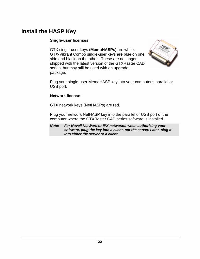
Install the HASP Key Single-user licenses
GTX single-user keys (MemoHASPs) are white. GTX-Vibrant Combo single-user keys are blue on one side and black on the other. These are no longer shipped with the latest version of the GTXRaster CAD series, but may still be used with an upgrade package.
Plug your single-user MemoHASP key into your computer’s parallel or USB port.
Network license:
GTX network keys (NetHASPs) are red.
Plug your network NetHASP key into the parallel or USB port of the computer where the GTXRaster CAD series software is installed. Note: For Novell NetWare or IPX networks: when authorizing your
software, plug the key into a client, not the server. Later, plug it into either the server or a client.

23232323
Authorize Your HASP Key NOTE You must authorize your software to obtain its full use!
An unauthorized MemoHASP allows 100 uses and an unauthorized NetHASP will limit your software to 100 uses per user up to 250 maximum uses.
Authorization Overview 1. Run CUSTOMER.EXE to get your HASP ID
2. Fill in the form and submit. Alternatively, you may use the enclosed blue authorization form and fax it to GTX.
3. Browse to www.gtx.com/authorize.asp
4. Within one working day, GTX will RETURN the authorization form with a RUS PASSWORD.
5. Run CUSTOMER.EXE and use MANUAL option to enter the RUS PASSWORD.
6. Your key is authorized!
DO YOU HAVE AN OLD GTX KEY? 1. If instructed on your new key’s envelope, return any old GTX key
as soon as possible because GTX cannot authorize your current key until your old key is received.
2. Unauthorized keys allow 100 uses to help you through this period. 3. The number found on your HASP key, the CD-ROM, and the box is
NOT your HASP ID. You must get the HASP ID by running CUSTOMER.EXE and selecting GET ID.
Authorization Instructions
RECORD YOUR HASP ID 1. Find your authorization form.
2. Plug the HASP key into the parallel or USB port.

24242424
3. Run CUSTOMER.EXE from a DOS prompt or double click the file from the Windows Explorer.
4. Select Get ID [ALT-G] to retrieve the HASP ID number.
5. Write your HASP ID number on the Authorization Form.
6. Exit the HASP ID NUMBER section of the CUSTOMER program by selecting OK [ALT-O].
7. Exit CUSTOMER [ALT-X].
SEND YOUR AUTHORIZATION TO GTX 1. Complete the Authorization form, making sure to add the HASP ID
number and your FAX number. The serial number should already be printed on your Authorization Form but if it is not, it is printed on the key and on the box.
2. FAX the Authorization Form to GTX:
ENTER THE RUS PASSWORD Within one business day, GTX will provide you with a RUS password (RUS=Remote Update System). Once you have your RUS password, run CUSTOMER.EXE again.
1. Select Manual [ALT-M]. Enter the RUS Password, using [TAB] between the separate pieces.

25252525
2. If the RUS password is entered correctly, a message should appear: Hasp Updated Ok
3. If GTX provides more than one Authorization Form, containing RUS passwords, the Customer program must be exited and restarted once for each Authorization Form. If you receive three sets of RUS passwords, you must run the Customer program three times.
The HASP key now allows unlimited uses of the GTXRaster CAD Series software. Note If you are using a single user license, you should be finished
installing the HASP key. If you have purchased a network license, continue with the following instructions. Otherwise, skip to Troubleshooting the Installation.
Network License Management Please refer to Start.chm, installed on your system by SETUP. This document describes installing the NetHASP system under various operating system and network protocols.
The three steps for establishing network license management are:
1. Install HASP device drivers by running HDD32.EXE on each workstation. You should have already performed this step, as described on page 20.
2. Configure each installed copy of the GTXRaster CAD Series for the appropriate operating system and network protocol by running the NetHASP Wizard or by editing the NETHASP.INI configuration file, as described in Start.chm.
Note The NetHASP Wizard creates its own version of NETHASP.INI and cannot read the existing version of this file. Rename your NETHASP.INI before running the wizard so you do not lose the original file.
3. Establish the correct license server for your operating system and network protocol. License servers include NHSRVW32.EXE.

26262626
Establishing Network License Servers The License Manager software can be run from a server or client. Refer to Start.chm for specific information. The NetHASP server can run as a Service, without a user logged into the NetHASP Server machine.
1. Run LMSETUP.EXE from the License subdirectory of the GTX installation directory.
2. The Status dialog appears. Select Next.
3. The Destination Directory dialog appears. Select the directory and then select Next.
4. Select Install as Service.
5. Select Install Device Driver.
You may alternatively install the NetHASP Server as a Windows application. This program must be running in order for the license manager to be available.
Check Profile Paths The GTX and BMPS, directories was added to the support file search path in the GTX AutoCAD profile (created during SETUP). If this path is not there, make sure you have the right profile (under AutoCAD's Config command).
Critical Configuration File Parameters Five configuration parameters are located in the configuration file, GTXRAST.CFG:
ProductLevel
ZERO_PLINE
HASPTIMEOUT
HASP_TYPE
DEMOMODE

27272727
PRODUCT LEVEL ProductLevel specifies the software level you intend to run. The installation sets this variable. If this variable is not listed, the program will default to RCADPLUS.
For GTXRaster CAD set ProductLevel = RCAD
For GTXRaster CAD PLUS set ProductLevel = RCADPLUS
For GTXRaster R2V set R2V
For GTXRaster TOOLS set RTOOLS Note: If the product level listed is different from the product you
purchased, your program will only run in demo mode. If you keep running in demo mode although you bought the product, make sure your product level is set to the correct level in the configuration file!
HASP TIMEOUT Determines the number of minutes of idle time the GTXRaster CAD Series license server will allow before de-activating an inactive license and making it available again.
DEMO MODE Controls whether GTXRaster CAD series runs in demo mode or attempts to find the HASP key and run as the product level specified by the ProductLevel configuration parameter. Demo mode allows nearly all functionality but limits the effective raster area to a 1,000 x 1,000 pixel area.
Valid entries: Yes, No
Adding the GTXRaster CAD Series to an Existing Profile SETUP generated an icon which runs AutoCAD with a profile in which GTX support paths and menus have been established. If you didn’t specify a profile during SETUP that would be the basis for the new GTX profile, a profile was created. If, after installing the GTXRaster CAD Series, you want to run it from a different existing profile:
1. Run AutoCAD under the profile to which you wish to add GTX.
2. Select Tools>Options.

28282828
3. Add the Raster CAD V9.0 and Raster CAD V9.0\BMPS directories to the Support File Search Path.
4. For the GTX and AutoCAD short cuts to work, you must “move up” the GTX support path directories to the top position.
5. Select OK.
6. The next time you run AutoCAD under the modified profile, GTXRaster CAD Series software should also run. Invoke Menuload and load the desired menus (GTXRtoolsV90.cui, GTXRcadV90.cui, GTXR2VV90.cui & GTXRcadPlus90.cui) to your existing menus.
You will not normally need to do this because the installation creates a profile with the required menus and support file paths.
Uninstalling the Software To remove the GTXRaster CAD Series software from your system, use Add and Remove Programs from the Control Panel.
Alternatively, you may run setup program from the CD ROM and select Uninstall.
Removing the GTX Application Files Note: Uninstall will not remove files that were not placed on your system
by SETUP, including modified configuration files, AutoCAD drawings or raster images. You need to remove those files yourself.
Now that AutoCAD is no longer looking for the GTXRaster CAD Series files, you can remove these files from your system.
29292929
Using the GTXRaster CAD Series
The Purpose of This Section This section describes the use of the GTXRaster CAD Series software. The GTXRaster CAD series is a program that operates within AutoCAD 2006 and many of its commands operate in a similar manner to AutoCAD commands. For example, in AutoCAD, the command for moving a CAD entity is MOVE. In the GTXRaster CAD Series, the command for moving raster data is gMOVE. Both commands use similar prompts to accomplish similar tasks.
Because GTXRaster CAD functions parallel AutoCAD’s, you will learn it more easily if you are familiar with the main AutoCAD functions, especially loading and saving drawings, attaching images, drawing and editing.
Raster and Vector The GTXRaster CAD Series lets you draw and edit, load and save raster information. Raster images are made up of dots (pixels) which represent pictures by forming an electronic mosaic. If you zoom close to a raster image, you will see each pixel as a square.
AutoCAD lets you draw and edit, load and save vector information. CAD drawings are made up of vector entities in which coordinates and other measurements are expressed mathematically in the CAD drawing. For example, a line is defined mathematically as the X and Y coordinates of each of its endpoints. A circle is defined as the X and Y coordinates of its center point and the length of its radius. Load a sample drawing into AutoCAD, window some of the entities and type LIST. You will see a barrage of entity types and coordinates. Note: It is easy to attach the same image twice in the same drawing.
Each image object refers to the same raster file, so if the image is somehow changed on the disk, the images will immediately change in the drawing!

30303030
AutoCAD 2006 and Raster Images AutoCAD lets you Attach raster images within vector drawings, displaying the raster within image entities. Image entities do not store the image data; they only refer, or link, to raster files already residing on disk. Attached raster files must be present for them to appear within AutoCAD. You can set properties for an image entity in a drawing, but these properties are only stored in the AutoCAD drawing, only affect the appearance of the image and do not directly affect the raster file at all.
AutoCAD will let you copy, move, rotate, resize and clip a raster image object within an AutoCAD drawing. The Image Adjust feature adjusts the display of an image’s brightness, contrast, fade and transparency.
An AutoCAD drawing provides an excellent framework for managing and modifying one or more related raster images. AutoCAD lets you display images to scale with the AutoCAD vector drawing coordinates.
What Does GTX Add to AutoCAD? The GTXRaster CAD Series adds raster enhancement, editing and conversion abilities to AutoCAD’s display and plotting capabilities. GTXRaster CAD can modify attached raster images and save them. GTX lets AutoCAD attach new raster formats. GTXRaster CAD extends AutoCAD’s AutoSnap feature to work on raster data, making it easier to trace over raster information with AutoCAD entities. The GTXRaster CAD Series lets you easily convert whole selections of raster into intelligent CAD entities within the AutoCAD drawing. GTX OSR provides batch conversion. GTXRaster R2V and GTXRaster CAD PLUS provide conversion clean-up tools to help make converted data more precise.
Product Functionality Loading Raster Images Into AutoCAD AutoCAD and GTXRaster CAD provide you with several ways of importing raster images. To load a raster image into AutoCAD, the software attaches it within AutoCAD drawing. The image is not stored in the .DWG file, but is viewed through it. When attaching an image, be sure of whether you are putting it in paper space or model space. Although the raster is only an image of a paper drawing, you can attach an image in model space and then scale the image entity so it is to scale with the AutoCAD coordinate system.

31313131
Learn to use AutoCAD’s IMAGE>Attach command before using any other methods. AutoCAD also supports dragging and dropping raster files of TIFF or .CAL raster formats.
GTXRaster CAD provides the gATTACH command to quickly attach images without prompting for insertion point, scale and orientation. Instead, it makes certain assumptions about how to place, scale and orient raster images.
Attach Method (Source)
IMAGE>Attach (AutoCAD)
� Command supported by AutoCAD
� Offers full control of insertion point, scale & orientation
� Numerous steps to import an image
Drag-and-Drop (AutoCAD)
� Easy to specify file - just drag it
� Still have to specify insertion, scale & angle
� Only works with TIFF, & CALS formats
gATTACH (GTX)
� One-step image import � Migrates earlier GTX
hybrid images to 2006 � Equivalent of gLOAD of
earlier GTX versions.
� Always inserts images that have no associated .REF file at same location, scale and orientation.
Scaling and Aligning Attached Raster Images Once an image has been imported into AutoCAD, it should be scaled and aligned to fit the drawing. Learn how to use AutoCAD’s SCALE command to properly scale the drawing. If you are working with line diagrams without a scale factor, you will probably want to bring attach images at a scale of 1, duplicating the original paper drawing. Use the scale factor of scanned drawings to determine how to scale its image entity to match the AutoCAD model space coordinates.

32323232
Example:
Having attached SIDE.CG4 from the GTX tutorial files at 0,0 at 0 orientation at scale of 1, the drawing would look like this:
The dimensions in the raster image indicate the required size of the raster if it were a drawing represented within AutoCAD’s model space.
The raster image will scale itself so that the geometry it portrays is to scale with AutoCAD’s model space. Note: Raster line widths will also scale along with raster images.
Orienting and Rotating Image Entities Often paper drawings are scanned sideways. If you used AutoCAD’s Image>Attach command to import a raster image, it may end up sideways. There are two ways to solve this problem:
ROTATE COMMAND GROTATE COMMAND
Command Explanation Command: SCALE Invoke the SCALE command Select objects: 1 found Select the SIDE.CG4 image entity Base point: 0,0 Scale from the base point 0,0 <Scale factor>/Reference: R Use a reference length to scale the
image entity Reference length <1>: Pick the first point along the 2
dimension Second point: Pick the second point along the 2
dimension New length: 2 Type what the dimension reports its
length to be

33333333
The gROTATE command rotates raster data within the raster image. It is useful for raster editing, but is not recommended as a tool for registering images within AutoCAD drawings.
AutoCAD’s ROTATE command can rotate the image entity, effectively correcting its appearance in the drawing. Some problems with this are:
� The insertion point is no longer the lower left point because it gets rotated along with the image entity.
� The image entity rotates about some base point, which can require additional adjustments to correctly line up the image.
GTURN COMMAND
The gTURN command can also be used to rotate an image, but it preserves the insertion point as the lower left point. Advantages of using this command are:
� The raster is turned inside the image entity, maintaining the lower left point as the insertion point.
� Because the raster turns rather than the image entity, the entity hasn’t moved about any base point. If the image was in the right position before invoking gTURN then it requires no further moving or adjusting.
Either technique positions raster data; gTURN does so in fewer steps.
Creating New Raster Images The GTX command, gCREATE, allows you to create a new raster image. Just like scanned images that were captured from paper or mylar drawings, new images should be drawn at some drawing scale. New raster images are limited to realistic sizes. Create new raster images that are approximately paper-sized, and then scale the image entities using AutoCAD’s Scale command.
For example, when creating a new image, you cannot make a raster image equivalent to a piece of paper the size of a city block. Instead, create a raster image the size of a large sheet of paper (E- or A0-size). Then scale the image entity with the Scale command. This way you can avoid attempting to create oversized raster images.

34343434
Cropping Raster Data Two commands are useful for erasing raster outside a rectangular area.
gCROP erases raster data outside a rectangular box. The raster image stays the same size.
gRESIZE removes the portion of the raster image outside a selected box. Raster data outside this box is erased because the raster image no longer occupies that space.
Modifying Images gACTIVE loads the image into the GTX editor, making it the current image for editing. If there is no active image, raster editing commands will invoke gACTIVE before proceeding. When there are multiple images attached, gACTIVE command will require you to select the image to prepare. If there is only one image attached in AutoCAD, gACTIVE will automatically prepare it. gINACTIVE releases the image, recovering memory.
Cutting and Pasting Raster

35353535
The GTXRaster CAD Series displays raster through AutoCAD image
entities, which can be attached at any scale or orientation. Because of this, the gCUT and gPASTE commands may behave differently than before.
Scanning a paper drawing Raster file at 270°
AutoCAD Image rotated at 90° gCUT a section from a rotated image
gCUT produces the cut data as a new image, which is at a 270° orientation, just like the source raster file:

36363636
Images oriented at angles other than 0 and 90 behave consistently. In this example, an image was inserted at a 30° orientation, and gCUT is used to create a new image. The cut image is taken from the source image at 0° - not at 30°:
Converting Between Raster and Vector The GTXRaster CAD series provides many commands that will convert data between CAD and raster formats. These commands are found under the GTXConvert menu.
For more information, see the references for the following commands:
VECTOR-TO-RASTER COMMANDS gRASTER, gBURN
gCUT from a rotated image
gCUT produces the cut data as a new image, which is at a 0° orientation, not at 30° like the source image entity. The border is larger than that specified during the gCUT command because it was cut at an angle.
AutoCAD image rotated at 30 °

37373737
RASTER-TO-VECTOR COMMANDS gCONVRT, gECONVRT, gTRACE, gVECTOR
INTELLIGENT CHARACTER RECOGNITION gTCONFIG, gTRAIN, gTCONVRT
Vector Cleanup The commands under the GTXVClean menu aid in cleaning up drawings after conversion from raster. For more information on each command refer to the light blue backed icons in the ‘Command Reference’ section.
Snapping to Raster GTXRaster CAD provides many transparent raster snap methods that help you select points precisely within raster images. But these raster snaps can be used when drawing raster or vector entities as well!
RASTER AUTOSNAP Better yet, GTXRaster CAD, GTXRaster R2V and GTXRaster CAD PLUS raster-enable AutoCAD’s AutoSnap™ feature in which a ToolTip appears to indicate the type of raster snap being employed.

38383838
The GTX command, gAUTOSNAP, controls whether AutoSnap™ will work within an image. Refer to the gAUTOSNAP command reference for more information.
Saving Images The GTXRaster CAD Series provides several ways of saving modified images. In addition to saving .DWG files, AutoCAD’s SAVE command will also save any changed images.
The gSAVE command lets you change the filename (and image name) of an image.
Command Description SAVE Saves .DWG and any modified images. GSAVE
Saves the current image. Optionally saves a .REF file along with the image.
QUIT When quitting AutoCAD, unsaved images can be saved. After saving, AutoCAD .DWG is saved.
GTXRaster CAD Series Performance Factors Because raster images can be so large, certain operating parameters affect system performance. In Minimum Requirements, we described the minimum recommended hardware configuration. The following AutoCAD and GTXRaster CAD Series parameters can also optimize display and editing speed:
Automatic Save Interval GTXRaster CAD Series saves modified raster images every time AutoCAD performs an Automatic Save. You can increase the time interval between automatic saves and minimize this kind interruption by increasing the AutoCAD SAVETIME system variable.
Swap Space Larger paging files can help performance when working with large raster images.
39393939
Aerial View The aerial view maintains a second copy of the image in memory. To save memory you can keep this view closed. Additional processing time is taken when the Aerial View is set to automatically update. Turn off the automatic update option after loading the drawing.
Current View/Zoom Redrawing images takes extra time. Performing a command generally takes longer if you are zoomed to extents than if you are zoomed in on a small area of the drawing.
Image Quality Set the Image Quality to Draft to save additional time. High quality slows processes. Raster plotting occurs at high quality even when images are displayed in draft mode.
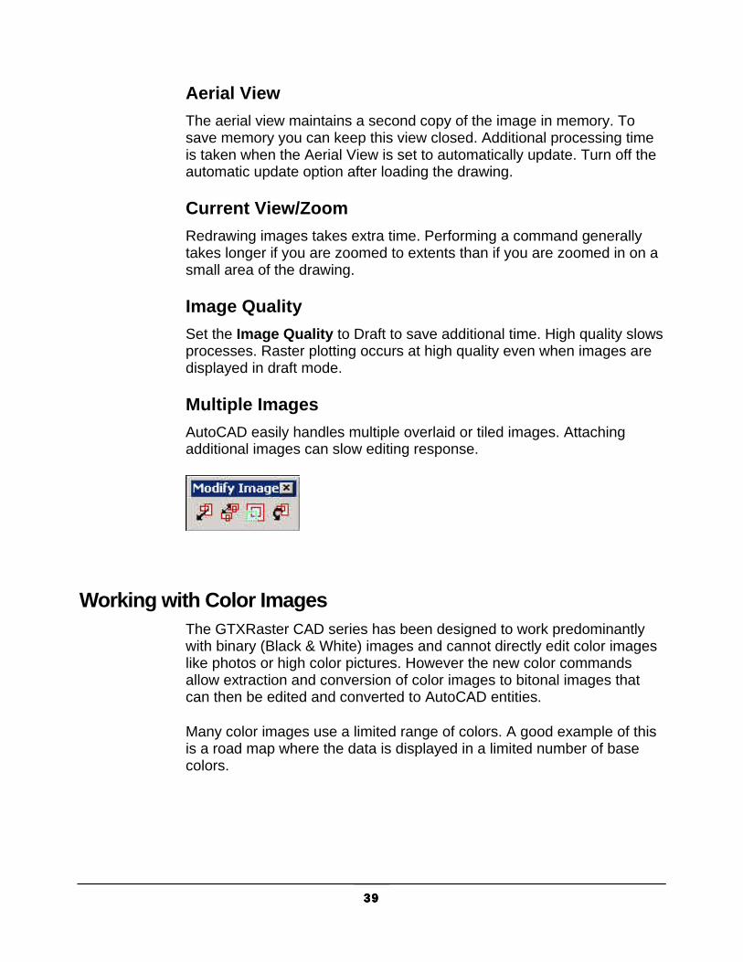
Multiple Images AutoCAD easily handles multiple overlaid or tiled images. Attaching additional images can slow editing response.
Working with Color Images
The GTXRaster CAD series has been designed to work predominantly with binary (Black & White) images and cannot directly edit color images like photos or high color pictures. However the new color commands allow extraction and conversion of color images to bitonal images that can then be edited and converted to AutoCAD entities.
Many color images use a limited range of colors. A good example of this is a road map where the data is displayed in a limited number of base colors.

40404040
In this example the roads are shown as black, the land contours are brown & the sea is blue. In these instances GTX provides commands to enable you to reduce the colors down to a more manageable range of colors. The GTX color related commands to do this are:
gBITONAL
gREDUCE
gSEPARATE
The best command to use depends mainly upon the number of colors that your image has.
Quick reduction to Binary.
If you wish to automatically reduce a color image down to a simple binary image you can use gBITONAL. The gBITONAL command has been optimized to operate on a broad range of color images & works well where an image has a clear-cut distinction between dark & light data.
However, the gBITONAL threshold may not give the exact results that you desire (by including or omitting important data from the binary image). In these instances it may be better to use the gREDUCE & gSEPARATE commands, where you have greater control of the color separation & threshold.

41414141
More than 256 colors.
If you have an image with greater than 256 colors you can firstly use gREDUCE to bring the image down to 256 colors or less.
Less than 256 colors.
For images with colors less that 256 colors, either before or after using reduction, you can use the gSEPARATE command. This allows you to accurately select colors, or groups of colors, & break then out into separate binary color images.
These separate binary images can, if required, be further processed using the full range of GTX capabilities & commands detailed elsewhere in this help file.
For more detailed information about each command's operation refer to the respective section in the 'Command Reference'.
Supported Color file formats.
When working with color images in GTX you can only save in
.tif (uncompressed TIFF),
.bmp (Uncompressed Bitmap),
.png (Portable Network Graphics),
.tga (Taga),.flc & fli (Autodesk FLIC) &
.pcx (PC Paintbrush) formats.
Also, if you originally loaded a .jpg (JFIF JPEG) file you will additionally be offered the option of saving in .jpg (JPEG) format.

42424242
JPEG Format files.
Although GTX can load & save .jpg (JPEG) files it is not an ideal operating format for GTX work. This is because JPEG is a format intended to work with pictures & photographs & when saving in JPEG format colors can automatically be added & removed from the color pallet. As such you can actively lose data by working & saving in JPEG format.
If possible we recommend that you save JPEG files in .TIF or .PNG format to avoid losing image definition.
Anti-Aliasing
Some color images are scanned with the ‘anti-aliasing’ option turned on. Anti-aliasng can enhance the quality of some images, particularly photographs. However it is not ideal for images with solid fill color as It tends to mix colors to achieve a more blurred image.
Whilst the gSEPARATE command will work with anti-aliased images the results may not be as good as required. As such we recommend that, if possible, images be scanned with anti-aliasing turned off.

43434343
Getting Started
Using the Tutorials To get the most from these lessons you should be familiar with AutoCAD 2006’s image commands. Experiment with the AutoCAD Image command to attach images within AutoCAD, ImageAdjust, ImageQuality, Transparency, basic drawing and property-modifying commands (entity drawing commands, the Properties command, Object Snapping modes).
Following the Lessons Try performing these exercises twice. The first time, follow the instructions literally to learn how each command and feature works. The second time, try to accomplish the same results as fast as possible, using the options and techniques with which you are most comfortable.
You won’t need to change your approach to working with AutoCAD to use the GTXRaster CAD Series. The toolbar icon and keyboard shortcut for each command and feature have been provided in the left margin.
Standardizing Your Environment for the Tutorials The lessons invoke GTXRaster CAD Series features from menus.
The AutoCAD variables CMDDIA and FILEDIA control whether dialog boxes are used in certain commands. If CMDDIA and FILEDIA are set to 1, many GTXRaster CAD Series commands use dialog boxes. If these variables are set to 0, many GTX commands will use AutoCAD command-line prompts. The lessons will describe the commands as they run with these variables set to “1”.
Editing a Raster File A typical editing session begins with enhancements that operate on most or all of the drawing. Next, make more detailed changes. Finally, focus on the overall picture to make sure the sections are properly matched and aligned.
44444444
1. The GTXRaster CAD Series cannot modify images until you prepare them for editing. (gACTIVE)
2. Get rid of meaningless or unwanted raster to reduce memory requirements and to clean the image. (gCROP, gSPECKL, gERASE)
3. Because documents are usually scanned at a slight angle, deskew raster drawings before proceeding. (gDESKEW)
4. Next, perform editing functions that involve the whole drawing or large areas of the drawing. (gMIRROR, gCUT, gPASTE)
5. Completely edit the image in one area before moving on to another area. Insert missing objects and correct distortions with both AutoCAD and GTX commands. Leave new entities in vector format or rasterize them using gRASTER. Use Raster Snapping methods to select points on raster geometry just as you do using object snaps.
6. Create and edit text. If using GTXRaster CAD PLUS, use gTCONVERT to convert raster text into AutoCAD text entities.
7. Look at the whole drawing and make any required changes (gCOPY, gMOVE, gROTATE and gSMOOTH).
8. Place new border and title block if needed.
9. Save the file. (SAVE, gSAVE, gCUT).
Lesson 1: Raster Cleanup In this lesson you will load a raster file and clean it using GTXRaster CAD enhancement commands. You will then edit it using a combination of GTXRaster CAD and AutoCAD commands. You will then save the edited file.

45454545
Load a Raster File The GTXRaster CAD Series software displays a vector CAD drawing in front of scanned raster images. You can edit the vector file in the foreground using the raster backdrop as a guide. You can use AutoCAD’s IMAGE>ATTACH command or GTX’ gATTACH command to load raster files directly into AutoCAD.
1. Run AutoCAD.
2. Select File>New to set up a new AutoCAD drawing:
3. Select the tutorial template file C:\Program Files\GTX\Raster CADV9.0\sample\GTXARCH.DWT. This template contains limits and views set up to standardize this exercise.
4. Select OK.
5. Note that in the upper left corner of the screen the filename is listed as Drawing.dwg. To change this, select File>Save.
6. Select OK.
Attach an Image Within AutoCAD 1. Select Insert>Raster Image....
2. Select the tutorial drawing, c:\program files\gtx\raster cad V9.0\sample\gtxarch.cg4 and click Open.
3. Make sure that the Insertion Point, Scale and Rotation “specify on screen” checkboxes are empty.
4. Type “0,0” for Insertion Point, type “1” for Scale and type “0” for Rotation.
5. Select OK.

46464646
6. The image is attached. Zoom ALL to view the entire drawing
7. Select File>Save to save the drawing, now with the image attached. Call this drawing <Your Name>.DWG.
8. Zoom to the drawing’s limits (Zoom, All).
In the second tutorial you will learn a faster way to attach a raster image in AutoCAD.
Rename an Attached Image Select GTXImaging>Save. Save the raster image with your name as the filename (c:\program files\gtx\raster cad V9.0\sample\<Your Name>.cg4).
The file has been saved under the new filename.
Enhance the Raster Image Now you will use GTXRaster CAD Series commands to clean up the raster drawing.
Use gDESKEW to Straighten the Drawing
This drawing is slightly rotated (skewed). You will use the gDESKEW command to straighten it. This command requires two points to define a reference line that should become either vertical or horizontal. You will use the vertical dimension line along the left of the image.
1. To see this area more clearly, you will use the tutorial view named “deskew”. Select View>Named Views...
2. Select the view named DESKEW, then Set Current and OK. The view will zoom closer to the image.

47474747
3. To edit this raster image, it must be prepared using the gACTIVE command. Select GTXImaging>Active Image. gACTIVE automatically sets gtxarch.cg4, the only attached image, as the active image.
4. Select GTXEnhance>Deskew. Select raster <WINDOW>:
5. Type All to select the entire drawing for deskewing. The entire drawing will be highlighted.
6. Press [RETURN] to stop selecting raster. Select one end of reference line:
The reference line follows a line that would become exactly horizontal or vertical after the image is deskewed. For the first point, you will use a raster-snap mode to select the lower left corner of the drawing.
7. Select GTXEdit>Raster Snaps>Intersection.
8. Select a point on the intersection of the dimension lines at the lower left. The reference line is anchored to the selected raster intersection.
Select other end of reference line:
9. Again, use the Intersection raster snapping option to select the point at the upper left corner. Intersection IOP can also be obtained by typing ‘rint, from the gtx pop-up menu (by holding [Control] while clicking the right mouse button) or through stacked IOP icon on the edit toolbar.
Deskewing 4.016183 degrees.
After a moment, the image will be straightened.
10. Zoom Extents to see the results.

48484848
Use gCROP to Clean Up Borders Often drawings are darkened, torn or speckled at the edges. The GTXEnhance>Crop command is a quick way to delete the unwanted raster around the outside of the drawing by letting you window the raster you want to keep. All raster outside the window is erased. gCROP decreases the size of the file, freeing memory.
1. Select GTXEnhance>Crop. Select first corner of window:
2. Select a point near the lower left corner of the drawing, just below and to the left of any significant objects.
Select opposite corner of window:
3. Stretch the window up and to the right until it encloses all the meaningful raster geometry, leaving only speckles outside.
All speckles outside the window are deleted.
4. If you made a mistake, select Undo and repeat the above steps.
Use gSPECKL to Remove Speckles Scanned drawings often contain unwanted smudges, gaps, stray lines and speckles. The gCROP command removed the speckles at the drawing’s edge, but there are still many speckles in the middle. The gSPECKL command can be used to filter speckles from the image without removing meaningful geometry such as decimal points. It can also be used to fill in small gaps in solid raster.
First, indicate the maximum size for the speckles (or holes) to be affected, then indicate whether you want to delete speckles or fill in holes.

49494949
Then, window the areas where the speckles or holes are. If punctuation marks or other significant objects are highlighted, Remove them from the pick list. The advantage of gSPECKL over gERASE is that you can make windows quite large since only objects fitting the speckle size will be affected. If unwanted speckles remain after the first pass, you can change to a larger speckle size for another pass just in the areas of the speckles.
1. It will be easier to see the speckles you are going to filter out of the image if you zoom into an area. Use the View command to set as current the view named “SPECK” to enlarge the rooms at upper left.
2. Select GTXEnhance>Speckle. Command: gSPECKLSpeckle size<0.00>/Box/Pick:
3. Type: P for Pick Select raster speckle:
4. Select a small speckle. Mode<Delete speckle>/Fill hole:
5. This time you are removing speckles, not filling in holes. Press [RETURN] to accept “Delete Speckle”.
Select raster<WINDOW>:
6. Type: V
The View option selects the current display. All of the speckles smaller than the selected speckle size will be highlighted on the screen. Pressing [RETURN] would delete all highlighted raster, but some of this is data. Despeckling can delete raster text characters such as “.”.
7. To avoid erasing text, type R for Remove and window around the meaningful raster to remove from the selection set. The Remove icon looks like a minus sign “-”, while the Add icon looks like a plus sign “+”.
Remove raster<WINDOW>:

50505050
Note that the prompt now reads, “Remove raster” instead of “Select raster”. Window areas of text until only speckles are highlighted. Press [RETURN] to end raster selection. The highlighted speckles will disappear from the screen. If you spent a long time removing useful information from the selection, then you chose too large a speckle when setting the speckle size. Next time you can select a smaller speckle or use the Box feature while selecting speckle size to specify a smaller speckle filter.
8. PAN one screen to the right by clicking to the right of the slider at the bottom of the screen. Start gSPECKL again. If the speckle size was adequate, you can use the same speckle size by pressing [RETURN] at the “Speckle size” prompt. Continue this step by despeckling the rest of the drawing.
Save Your Changes After spending time editing the drawing you will want to save the changes. You will want to save the image to a different name to preserve the original tutorial image.
Select File>Save. This will save not only the AutoCAD drawing but also the attached raster image.
Edit Raster Geometry You are ready to use the GTXRaster CAD Series raster editing commands to change the drawing.
Use gCOPY to Copy Raster Geometry 1. Zoom in on the upper-left room, including some of the empty space
to its left.
2. Select GTXEdit>Copy. Select raster<WINDOW>:
3. Use the Window option to select the room.
4. You will not want to copy everything, however, so type R for Remove. Note that the prompt changes to Remove Raster:
Remove raster <WINDOW>:
5. Type L for Line.

51515151
Select one end of reference line:
You will remove the horizontal dimension line just below the top wall of the room.
6. Select a point beyond the left end of the line. Select other end of reference line:
7. Select a point beyond the right end of the line. The line will be removed from the selection set.
Remove raster <LINE>:
8. Likewise, remove the vertical line just inside the left wall.
9. Press [RETURN] to finish selecting raster geometry.
Base point or displacement:
10. Select a point near the lower right corner of the room. Second point of displacement:
11. Select the point for the copy placement. It should be to the left of the drawing, so the results appear as shown in the figure below. The copy of the room will appear.
Use gERASE to Remove Raster Geometry
You will use gERASE to remove the text, the vertical line and the little box where the lines intersected.
1. Select GTXEdit>Erase. Select raster<LINE>:
2. Type I for the Inside picking method.
3. Window around the text: “OFFICE”, the little box containing “125”, and the small square in the upper left corner.
4. Press [RETURN]. All clear!

52525252
Use gSCALE to Resize Raster Geometry 1. Select GTXEdit>Scale. Select raster<INSIDE>:
2. Select the copy of the room and press [RETURN]. You will need to draw a rectangle that completely encloses the copy of the room with no part of it extending outside of your window because the Inside selection method is still being used. To do this you may have to pan or zoom.
Base point:
3. Select the lower right corner of the room. Scale factors<1.0,1.0>/Fit:
4. Type: 1.5,1.5
The room will be enlarged. You may need to Zoom out to see it.
5. In the scaled copy of the room, draw a vector rectangle and a circle to represent a desk and chair. Keep some space in between the table and the top wall as shown in the illustration below:
Use gRASTER to Rasterize Vector Geometry Now you can incorporate these vector entities into the raster drawing with the gRASTER command.
1. Now select GTXConvert>Rasterize.
Select objects:
2. Select the rectangle and circle representing the chair and desk.
3. Press [RETURN]. The Rasterize Setup dialog will appear.
4. Select the Table radio button and the Table Setup button. The Line

53535353
Width Configuration table will appear, showing line widths of raster entities to be generated from each color of vector entity.
5. Note the color of the vector entities drawn and the color’s corresponding raster width and select OK. Select OK again in the Rasterize Setup dialog to accept the parameters.
Rasterize in progress .. 2 segmentsPercent complete = 100.0
The entities will be converted to raster with a width corresponding to .04 inches, assuming the entities were Color 7 = “White” (or black if your background color is white).
6. Suppose the raster was too thick. Select Undo to return the raster and vector to the way it was before rasterizing.
7 Select gRASTER and again select the entities.
8. Type: .02 in the Fixed Width text field.
Entering .02 specifies the absolute width for all entities, regardless of color. This absolute value will be the default width for subsequent commands.
Use gCUT to Save Selected Raster Geometry You could add furniture to the other rooms in the layout if you scale it down. You can copy, scale and even rotate all with the gPASTE command. First you have to gCUT the raster before it can be pasted. Raster is selected and written to a separate raster file or buffer and can be pasted elsewhere. The gCUT and gPASTE combination works similar to the AutoCAD BLOCK and INSERT or CUTCLIP and PASTECLIP commands. It allows you to create standard images that can be placed repeatedly in one drawing or in different drawings even if the scale is not the same.
1. Select GTXEdit>Cut. Mode <Copy>/Erase:
2. Press [RETURN] to select Copy. Select raster<INSIDE>:
3. Window around the desk and chair. They will be highlighted. Press [RETURN].
Select lower left corner of raster limits:

54545454
4. The lower left corner becomes the “insertion point” when pasting the image. Select a point below and to the left of the highlighted objects as if you were picking the first point for a window.
Select upper right corner of raster limits:
5. Select the second point near and above and to the right of the desk. Destination File/<Buffer>:
6. Type F to copy the selected raster to a file.
7. Save the file to C:\Program Files\gtx\raster cad V9.0\Sample\desk.cg4.
Replacing Raster Text with Vector Text 1. Zoom in on the lower right office.
2. Type AutoCAD text over the raster text.
3. Move the AutoCAD text to the lower left corner of the room.
4. Select GTXEdit>Erase. Select raster<WINDOW>:
5. Type IN to select Inside a rectangular box.
6. Draw a rectangle around the raster text in the lower right room.
7. Press [RETURN].
The text is erased.
Use gPASTE to Insert Cut Raster Geometry You will next paste the desk first into the room at the lower left.
1. Zoom in on the room in the lower-left office in the drawing.
2. Select GTXEdit>Paste. Source File/<Buffer>:

55555555
3. Type F to paste data from a raster file.
4. Select C:\Program Files\GTX\Raster CAD V9.0\Sample\desk.cg4.
5. Select a point inside the room near lower left corner. It does not have to be in the exact spot as you can adjust the location later.
Loading raster -- DESK.XXX ...Move/Rotate/Scale:
6. The data will appear with its lower left corner at the insertion point. Obviously the scale is too large. Type S to select the Scale option, highlightling the pasted raster.
Base point:
7. Select a point at the lower left corner of the desk-chair arrangement. Scale factors <1.0,1.0>/Fit:
8. Type 2/3,2/3
The data will be made smaller and the highlighting will disappear.
Move/Rotate/Scale:
9. Select Move. Base point or displacement:
10. Select the upper left corner of the desk. A line will rubber-band from this point.
Second point of displacement:
11. Move the box such that the furniture is next to the door in the wall at the top of the room.
Move/Rotate/Scale:
12. You can keep moving the image around, or press [RETURN] to exit the command when you are satisfied.
Use gCOPY to Copy Raster Geometry 1. Zoom ALL
2. Select GTXEdit>Copy.
3. Type: PR for Previous, highlighting the pasted raster.

56565656
4. Press [RETURN]. Base point or displacement:
5. Select the upper left corner of the “desk”. Second point of displacement:
6. Select a suitable location in the middle of the lower right office, creating a copy of the image.
7. You can continue to copy the same image to other locations by re-selecting the command and PRevious and then selecting points.
Use gROTATE to Rotate Raster Geometry Perhaps you would prefer to have the desk turned a different way in some rooms.
1. Zoom in on the lower right room.
2. Select Edit>Rotate from the menu. Select raster<WINDOW>:
3. Type O to use the Object picking method. Select the left mouse button on the desk and chair in the lower left office. The desk will be highlighted. Press [RETURN] when done.
Base point:
4. Select a point in the center of the chair. Rotation angle <0.0>/Reference:
5. Type: -90
6. Select Yes to delete the original un-rotated desk.
7. Select gMOVE and PRevious to reposition the image to the desired location.
Base point or displacement
8. Select the upper left corner of the desk. A line will rubber-band from this point.
Second point of displacement:
9. Move the furniture to the right.

57575757
10. Select File>Save to save your changes.
End the Session You are now finished editing this drawing.
1. SAVE the AutoCAD drawing, the changes made to the raster image were also saved.
2. CLOSE the drawing.
Loading Your New Drawing OPEN <Your Name>.DWG. The drawing will load just as you saved it.
What You’ve Learned Congratulations! You have completed the first lesson on cleaning up a drawing.
You learned to use:
� gSAVE to save an attached image to a new filename.
� gACTIVE to prepare an image for editing.
� gDESKEW to straighten a skewed image.
� gCROP and gSPECKL to remove unwanted raster.
� gCOPY and gSCALE to enlarge a portion of the image.
� gRASTER to incorporate vector elements into the raster image.
� gCUT and gPASTE to create images and insert them within other images.
� Raster Picking and Raster Snapping methods to select raster for editing.
� gERASE and gUNDO to correct mistakes.
� gSAVE and gCUT to save raster.

58585858
Lesson 2 : Raster Revision You will load a drawing that has a few errors and needs revision. You will use raster editing tools to make the necessary changes and selectively vectorize part of the drawing. You will use two images in one drawing.
Load a Raster File 1. Select File>New to start a new drawing. The Create New Drawing
dialog will appear:
2. Use the template, C:\Program Files\GTX\Raster CAD V9.0\Sample\GTXMECH.DWT. Select OK.
3. Save this drawing to change its name from Drawing.dwg. Invoke the AutoCAD SAVE command:
4. Enter your name with a “2” after it (C:\Program Files\GTX\Raster CAD V9.0\Sample\<Your Name>2.cg4) under New Drawing Name.
5. You will use the gATTACH command to quickly attach a raster image. Select GTXImaging>Quick Attach (you can also type GA for short).
6. Select C:\Program Files\GTX\Raster CAD V9.0\Sample\gtxmech2.cg4 as the raster file to load. The raster file is immediately attached at 0,0 at a scale of 1 and an orientation of 0 degrees.
7. Zoom All. Notice that the raster data is rotated 90 degrees from 0 upgright. If you do a LIST on the image entity you’ll notice that its rotation angle is 0 degrees. To correct this, you will have to rotate the raster 270 (= -90) degrees. Instead of using AutoCAD’s ROTATE command, you will use gTURN.
8. Invoke gTURN.
Specify rotation angle <90>/180/270:

59595959
9. Type 270 and press [RETURN]. This rotates the raster data to 0° without rotating the AutoCAD image object.
Renaming the Raster File So that you do not save this raster image over the tutorial drawing, you will save it to another name:
1. Select gSAVE.
2. Give the raster file a new name - name it your name with a “2” after <Yourname>2.cg4.
3. Invoke gINFO by selecting File>Information. This command tells you about the (new) current raster image. Press [RETURN] to continue.
Scaling the Image Paper drawings are created “at scale” to fit within the paper’s limits. CAD is typically created at a 1:1 scale because there is no limit to the distance CAD can represent. The attached image entity must be scaled so a distance in the raster becomes equivalent to an AutoCAD distance.
1. Use the AutoCAD VIEW command to set as current the view named, “Scale”. The view will have zoomed in on the upper half of the drawing, as shown above. To the left is a dimension indicating a horizontal distance of “6.25”.
2. Invoke the AutoCAD SCALE command Select Objects
3. Select the image by typing ALL. Base point:
4. Type 0,0. <Scale factor>/Reference:
5. Type R for “Reference”. Reference length <1>:

60606060
6. Use the ‘rend raster snap to select one end of the horizontal “6.25” dimension line.
Second point:
7. Select the other end of the dimension line. New length:
8. Type: 6.25 to set the specified distance to 6.25 drawing units.
The scale of the image object will be adjusted so that the distance between the dimension lines becomes 6.25 units long. You can use the AutoCAD DIST command to verify this.
Enhance the Raster Image Note: To start gDESKEW the program needed to prepare the image for
editing with the gACTIVE command. Because there is only one image, it automatically activates it. Most raster enhancing/editing commands will start gACTIVE if there’s no active image!
Now you will use enhancing commands to clean up the raster drawing.
Use gDESKEW to Straighten the Drawing Because there are few speckles and no border to remove (using gCROP), you can skip despeckling and start deskewing the drawing.
1. Zoom all.
2. Select GTXEnhance>Deskew. No raster image selected. Invoking gACTIVE commandLoading raster -- C:\Program Files\GTX\Raster CADV9.0\Sample\gtxmech2.cg4 ...
Select raster <WINDOW>:
3. Type All to select the entire drawing for deskewing. Press [RETURN] to complete selecting raster.
Select one end of reference line:
4. Type ‘rint to use the “intersection” raster snap mode. Using the ‘rint raster snapping method, select two points on the horizontal centerline that bisects the largest circle.

61616161
5. Select an intersection on this line on the left side of the image. Select other end of reference line:
6. Type ‘rint again and select another intersection point on the right side of the same line.
The selected raster will straighten.
Edit Raster Geometry Use gCHANGE to Modify a Circle 1. Restore the view named “Change”. The view will zoom to the lower
left quarter of the drawing.
The dimensions on the left side of the drawing show the large hole in the center of the drawing to have a diameter between 2.2400 and 2.2409 inches.
2. Use the AutoCAD DIST command to measure the diameter of the circle. It appears to be roughly 1.5”, so it is not to scale. You will use the gCHANGE command to modify the radius to 1.12”, half of the stated diameter, 2.2400”.
3. ZOOM close to the circle.
4. Select GTXEdit>Change. Select raster <LINE>:
5. Type C for Circle. Select point on circumference ofcircle:
6. Select a point on the circle. Select second point for circle:
7. Select another point on the same circle.
Select third point for circle:
8. Select a third point, as far from the other two as possible. The raster circle highlights.
Enter circle radius:
9. A line will rubber-band from the center of the circle. You can either select a point or enter a value to indicate the new radius. Type: 1.12

62626262
The circle will stretch to the specified radius.
Use gCHANGE to Modify a Line The dimension indicating the circle diameter should be modified. First, extend the diagonal line that connects the circle with its dimension text, as shown below:
1. Press [RETURN] to reselect gCHANGE. Select raster <CIRCLE>:
2. Type L for Line. Select one end of reference line:
3. Type ‘rend and select the lower left end of the line that is extending from the circle.
Other end of line:
4. Use ‘rend again to select the present upper-right point of that line. Select new endpoint:
5. Use ‘rnea to select the point on the circle opposite from where the dimension line enters it. The line will now be extended across the circle.
Now that the line is fixed, you will use gMOVE to move the small arrowheads to the edge of the circle.
6. Select GTXEdit>Move. Select raster <WINDOW>:

63636363
7. Draw a window around the upper-right arrowhead large enough so that you include some of the line running through it.
8. You will now remove the shaft of the arrow from the selection set. Type R for Remove.
Remove raster <WINDOW>:
9. Type L for Line.
10. You will select two points on the line on either side of the arrow, removing the line from the selection set while leaving the triangular arrow. Select one end of reference line:
11. Select the first point above and to the right of the arrow. Select other end of reference line:
12. Select the second point on the line below and to the left of the arrow.
Remove raster <LINE>:
13. Press [RETURN] to finish selecting raster.
Base point or displacement:
14. Select a point near the tip of the arrow. Second point of displacement:
15. Use ‘rint to select the intersection of the line and the upper right edge of the circle. The arrow will move to touch the inside of the circle.
16. Now move the other arrow down to the lower left edge of the circle so it appears as shown below. Be careful in selecting the arrowhead so you do not accidentally move the nearby leader line:

64646464
Converting Raster to Vector You will now convert some of the raster geometry into AutoCAD vector entities using GTXRaster CAD commands.
Use the “Edge” Raster Snap to Draw a Solid Zoom in on the circle to see the two
large arrowheads.

65656565
Note If you are running GTXRaster Tools, skip to step 5. If you are running GTXRaster CAD, GTXRaster R2V or GTXRaster CAD PLUS, proceed with steps 2 through 4. You can determine which product you are running with the gINFO command.
Select Control-Right Mouse Button. A pop-up menu appears. Select Raster AutoSnap ON. This enables AutoCAD AutoSnap™ to “object-snap” to GTX raster data.
Invoke AutoCAD’s OSNAP command.
Select only NODE object snapping setting. NODE will cause GTXRaster CAD to snap to the edges of solid raster areas.
Make sure that Object Snap On is checked.
Press OK.
5. Use the AutoCAD SOLID command to trace the large arrowheads. Select three points, then press [RETURN] for the fourth point to complete a solid triangle. (Do not select a fourth point).
6. Perform this process for both arrowheads.
Note You will have drawn two AutoCAD Solid triangular entities representing the arrowheads. If your raster data is the same color as vector objects, then these arrowheads may be difficult to see. If this is the case, zoom all, select the raster object by clicking on its frame, and change its color to red. Then use AutoCAD’s REGEN command. The arrowheads will be very visible against the now red raster data.
Use the “Nearest” Raster Snap to Draw a Polyline 1. Zoom in on the irregular hole in the lower right section of the
drawing, as shown below.
2. If you performed the AutoSnap steps above, use the OSNAP command and select NEAREST and END. If you are running GTXRaster Tools, continue without performing this step.

66666666
3. Use the AutoCAD PLINE command to trace the irregular hole. When you are almost done digitizing the hole, type C to Close the polyline.
4. If you were using AutoCAD’s AutoSnap™ on raster, de-activate it by selecting OSnap/Clear All. Then, use Control-Right mouse button and select Raster AutoSnap OFF.
Use gTRACE to Convert a Raster Line to Vector 1. Select GTXConvert>Trace Vectors.
2. Select raster <LINE>:
3. Select the tip of the left arrow that extends out of the irregular hole you just traced, then the right end of the arrow’s shaft. GTXRaster CAD will draw an AutoCAD line over the raster line, but not over the arrowhead itself.
4. Likewise, trace the right-hand dimension arrow shaft.
Use gRUB to Erase all Raster Underlying Vector Entities Now you will erase the raster under the new vector entities.
1. Zoom All so you can see all the vector entities drawn since step 1.
2. Select GTXEdit>Rub. Select objects:
3. Select all the vector entities and press [RETURN].
The raster underlying the entities will be erased.
4. Select File>Save to save both the drawing (vector) and raster files.
Combining Raster Drawings Now you will add another view of this device into the drawing.
Use gPASTE to Insert a Raster Image You will now paste the new view, called Side, into the raster image.
Select GTXEdit>Paste. Source File/<Buffer>:

67676767
1. Type F for File. The file dialog will appear:
2. Select C:\Program Files\GTX\Raster CAD V9.0\Sample\SIDE.CG4. Insertion point:
3. Type: 20,20 Loading raster -- C:\Program Files\GTX\Raster CADV9.0\Sample\side.cg4 ...Move/Rotate/Scale:
The side view will reappear above and to the right of the detailed top view, but it is rotated 90 degrees. gPASTE lets you adjust the pasted data.
4. Type R for Rotate and the pasted image will be highlighted.
Base point:
5. Select a point in the middle of the pasted raster data.
Rotation angle <90.0>/Reference:
6. Enter -90 to rotate the image upright.
Move/Rotate/Scale:
7. Complete the gPASTE command by pressing [RETURN] at the Move/Rotate/Scale prompt.
Making a Frame
You will now draw a frame around the drawing. A vector line would look rather thin, but it could be rasterized to make a frame using thicker lines.
1. Draw an AutoCAD Rectangle around the drawing but inside the raster boundary.

68686868
2. Select GTXConvert>Rasterize. Select objects:
3. Select the rectangle. Press [RETURN] to complete the selection.
4. Select Box. Select first corner of box:
5. Select a point on the lower edge of any horizontal line. Select opposite corner of box:
6. Move the cursor along the line and slightly above it to make a long thin horizontal window, simulating the line for the frame. The length of the box does not matter; the shortest side of the box provides the final width of the raster.
Notice that the value in “Fixed Width” has changed; this is the width you specified with the box.
7. Select OK. The frame will be redrawn in the raster image with thick lines.
Save the Drawing 1. Issue the AutoCAD Quit command.
2. Select Yes when you are prompted to save the changes.
This saves both the drawing and raster.
Loading Hybrid Drawings 1. Run GTXRaster CAD again so you can load all the information back
into GTXRaster CAD at once.
2. Select File>Open from the menu:

69696969
3. Select C:\Program Files\GTX\Raster CAD V9.0\<Your Initials>.DWG as the filename.
AutoCAD will load the vector file and will also display the attached raster image.
What You’ve Learned Congratulations! You have now completed the second tutorial lesson. You have learned to use:
� gATTACH to load a drawing.
� gCHANGE, gMOVE and gRUB to modify raster geometry.
� gCOORDS to adjust the scale of a raster drawing (gCOORDS is an AutoLISP routine that can be loaded).
� Raster-snapping to select precise points in the raster image.
� gTRACE to convert raster geometry to vector entities.
� gSAVE to save specific raster images.
� END to save any modified raster images.
� Open to load hybrid raster and vector drawing files.
Lesson 3: Raster to Vector This lesson uses commands available only with GTXRaster CAD PLUS and GTXRaster R2V. If you are running GTXRaster Tools, skip this tutorial.
When a drawing needs more than a few minor modifications it can be worthwhile to convert it entirely to vector format. GTXRaster CAD PLUS provides powerful tools for accomplishing this quickly and accurately.

70707070
Summary of GTX Conversion Commands: Command Icon Program Action gTRACE
None GTXRaster CAD, GTXRaster CAD R2V or GTXRaster CAD PLUS
Converts specified raster lines, arcs and circles to vector. Leaves raster intact.
gVECTOR
None GTXRaster CAD, GTXRaster CAD R2V or GTXRaster CAD PLUS
Replaces specified raster lines, arcs and circles with vector ones.
gECONVRT
GTXRaster CAD R2V or GTXRaster CAD PLUS
Vectorizes the raster edge created in raster mode.
gCONVRT GTXRaster CAD R2V or GTXRaster CAD PLUS
Converts selected raster data into lines, arcs, circles and arrowheads or polylines.
gTCONVRT
GTXRaster CAD R2V or GTXRaster CAD PLUS
Converts selected raster text into AutoCAD text entities.
Loading a Raster File 1. Invoke the AutoCAD NEW command. The Create New Drawing
dialog will appear.
2. Select Start from Scratch and choose English (feet and inches).
3. Select GTXImaging>Quick Attach.
4. Select Gtxvbelt.cg4 from the GTX program directory and press OK. The image was scanned sideways, so the image must be turned 90 degrees back to normal!
5. Is GTXVBELT rotated? If so, select GTXEnhance>Turn. Otherwise, skip to step 7.
Specify rotation angle <90>/180/270:

71717171
Note: gTURN helps when images are scanned in sideways because it quickly rotates them to the correct angle.
6. Press [RETURN] to accept the default 90 degree rotation.
The raster data is rotated 90 degrees while leaving the lower left corner at 0,0 and the orientation at 0 degrees.
Use gCONVRT to Convert Raster to Vector First, you will convert the table in the upper right corner to AutoCAD lines.
1. Zoom in on the table in the upper right corner of the drawing.
2. Select GTXConvert>Vectorize. Select raster <WINDOW>:
3. Type F for the Fence raster picking method. First fence point:
4. Draw a short line across one of the table grid lines without touching any raster text.
Undo/<Endpoint of line>:
5. Press [RETURN] to finish drawing the fence line. This will select the entire grid without selecting the enclosed text.
Select raster <Fence>:
6. Press [RETURN] again to finish selecting raster. The Raster Convert Setup dialog will appear (See gCONVRT, page 125).
7. Make sure the Vector Color>By Width checkbox is empty. This will ensure that the resulting vectors are generated with the current layer’s color and linestyle.
8. Verify that Rectify Ortho is selected. This will snap nearly orthogonal lines to 0 and

72727272
90 degrees.
9. Un-check Save Raster so the original raster will be replaced with the resulting vector entities.
10. Select OK. Processing Image...
The table will be converted to AutoCAD line entities.
11. Use the AutoCAD LIST command to check a few of the resulting lines. Verify that the raster lines were snapped to exactly vertical or horizontal orientations when they were converted to vectors (“Angle in XY Plane = 90, 180, or 270”).
Converting Raster Text to AutoCAD Text Entities gTCONVRT converts selected raster text into AutoCAD text entities. If a raster text character is drawn poorly or if it is ambiguous (i.e., it looks very much like another character) the command will require you to verify it using the Character Verification dialog.
USING GTCONFIG TO CONFIGURE THE TEXT RECOGNITION Read the command references for the gCONVRT, gTCONVRT, and gTCONFIG commands.
1. Select GTXConvert>Text Convert. Because you have not yet configured text conversion, the Text Configuration dialog appears. This dialog sets up the details required to convert raster text into AutoCAD text entities. The dialog contains four panes: Raster Input, Character Recognition, Word Recognition and Text Output. The dialog starts on the first pane, Raster Input.
Raster Input Pane

73737373
The IOP section limits the range of text sizes that can be selected using text window IOP or text line IOP. It also limits the size of distinct raster entities that can be processed by gTCONVRT as text. Set the Min Char Size slightly lower than the size of small punctuation marks (“.”). This insures that punctuation marks, but not speckles, will be converted. Note: In speckled drawings you should use the gSPECKL command
before doing any conversion. This tutorial skips speckle removal because this drawing has few speckles.
Because text characters are sometimes touching, it is good to set the Max Char Size slightly larger than two times the size of a typical large character.
1. Set the Min Char Size to .03 (the default value of .04 won’t select all the decimal points in this table).
2. Leave the Max Char Size at “.4”. This should work fine for this drawing because most text characters are only about .2” tall (you can use the AutoCAD DIST command to sample text sizes first).
The String Formation section controls how AutoCAD text entities are formed from individual raster characters. Space Size represents the distance (in terms of the portion of a character’s width) between two raster characters required to insert “space character” between them. Max # Spaces represents the maximum number of space characters allowed before the characters need to be split into two separate AutoCAD text entities. Alignment Offset represents the vertical offset allowed between two characters that are of the same text string.
3. Looking at the third and fourth columns of the table, you can see that the space between text strings can be even less than one character’s width. Set the Space Size to .75.
4. Leave Max # Spaces at “3” so that several space characters can be fit between two characters. If gTCONVRT finds more than 3 spaces between two characters they will be separated into separate text entities.
Character Recognition Pane

74747474
Select the Character Recognition tab. The Recognition Files section controls which recognition files (suffix = ICR) are being used to recognize the raster text. Recognition files contain sample raster text which is compared to the text being converted, so it is important to choose file(s) whose samples best match the raster text being converted. For this tutorial
you will use the file: TUTORIAL.ICR.
1. Select the button labeled OPEN or NEW. A file dialog appears.
2. Select Tutorial.icr from the GTX program directory and press OK.
The Auto-Convert Threshold determines the confidence level at which a character must be recognized for gTCONVRT to automatically convert it to an AutoCAD text entity. Characters recognized at confidence levels below the Auto-Convert Threshold will be displayed in the Character Verification dialog before they are made into text entities. The default value for the Auto-Convert Threshold is “100”. Leaving it at this value would force the Character Verification dialog to appear for every character. Instead, set this value to 85. Characters recognized at a confidence above 85 will be automatically converted into text entities.
Text Output Pane
The Orientation list contains all orientations allowed for resulting text entities. The default orientation is “0” and this will work because all the raster characters in the drawing are upright.
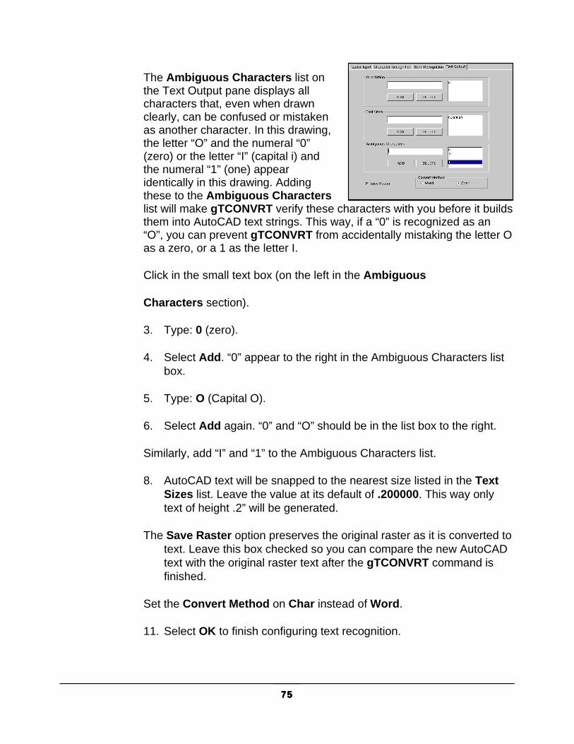
75757575
The Ambiguous Characters list on the Text Output pane displays all characters that, even when drawn clearly, can be confused or mistaken as another character. In this drawing, the letter “O” and the numeral “0” (zero) or the letter “I” (capital i) and the numeral “1” (one) appear identically in this drawing. Adding these to the Ambiguous Characters list will make gTCONVRT verify these characters with you before it builds them into AutoCAD text strings. This way, if a “0” is recognized as an “O”, you can prevent gTCONVRT from accidentally mistaking the letter O as a zero, or a 1 as the letter I.
Click in the small text box (on the left in the Ambiguous
Characters section).
3. Type: 0 (zero).
4. Select Add. “0” appear to the right in the Ambiguous Characters list box.
5. Type: O (Capital O).
6. Select Add again. “0” and “O” should be in the list box to the right.
Similarly, add “I” and “1” to the Ambiguous Characters list.
8. AutoCAD text will be snapped to the nearest size listed in the Text Sizes list. Leave the value at its default of .200000. This way only text of height .2” will be generated.
The Save Raster option preserves the original raster as it is converted to text. Leave this box checked so you can compare the new AutoCAD text with the original raster text after the gTCONVRT command is finished.
Set the Convert Method on Char instead of Word.
11. Select OK to finish configuring text recognition.
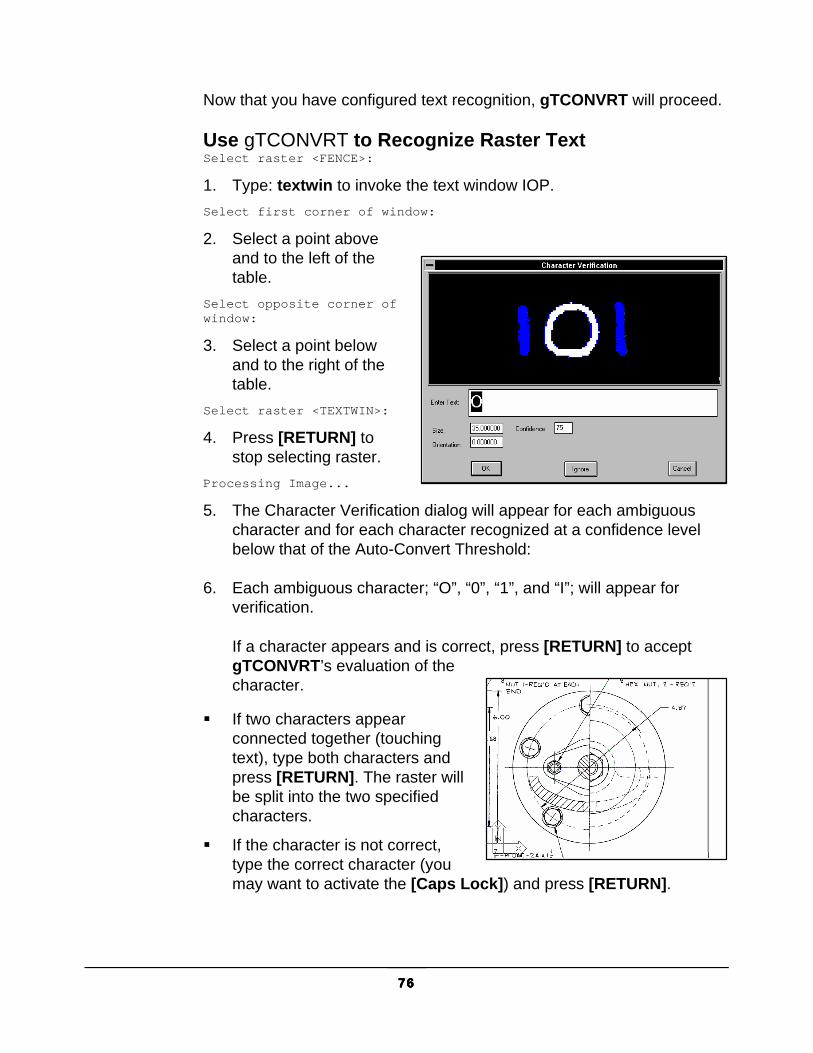
76767676
Now that you have configured text recognition, gTCONVRT will proceed.
Use gTCONVRT to Recognize Raster Text Select raster <FENCE>:
1. Type: textwin to invoke the text window IOP. Select first corner of window:
2. Select a point above and to the left of the table.
Select opposite corner ofwindow:
3. Select a point below and to the right of the table.
Select raster <TEXTWIN>:
4. Press [RETURN] to stop selecting raster.
Processing Image...
5. The Character Verification dialog will appear for each ambiguous character and for each character recognized at a confidence level below that of the Auto-Convert Threshold:
6. Each ambiguous character; “O”, “0”, “1”, and “I”; will appear for verification.
If a character appears and is correct, press [RETURN] to accept gTCONVRT’s evaluation of the character.
� If two characters appear connected together (touching text), type both characters and press [RETURN]. The raster will be split into the two specified characters.
� If the character is not correct, type the correct character (you may want to activate the [Caps Lock]) and press [RETURN].
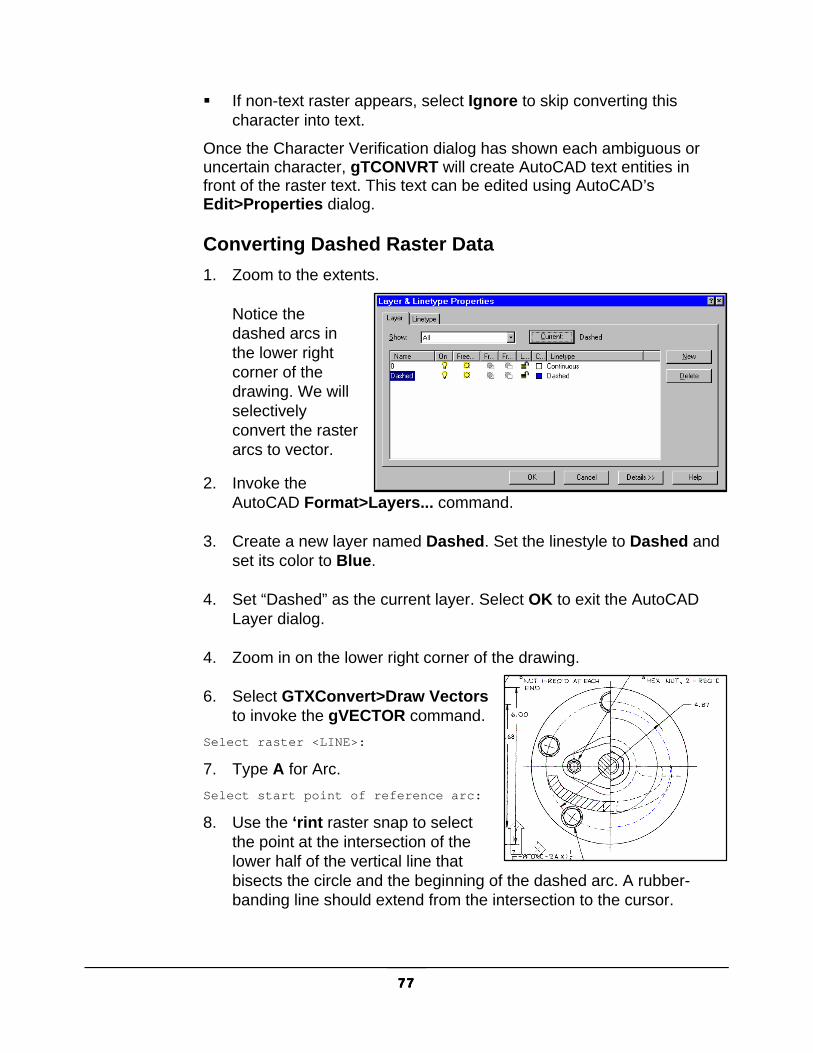
77777777
� If non-text raster appears, select Ignore to skip converting this character into text.
Once the Character Verification dialog has shown each ambiguous or uncertain character, gTCONVRT will create AutoCAD text entities in front of the raster text. This text can be edited using AutoCAD’s Edit>Properties dialog.
Converting Dashed Raster Data 1. Zoom to the extents.
Notice the dashed arcs in the lower right corner of the drawing. We will selectively convert the raster arcs to vector.
2. Invoke the AutoCAD Format>Layers... command.
3. Create a new layer named Dashed. Set the linestyle to Dashed and set its color to Blue.
4. Set “Dashed” as the current layer. Select OK to exit the AutoCAD Layer dialog.
4. Zoom in on the lower right corner of the drawing.
6. Select GTXConvert>Draw Vectors to invoke the gVECTOR command.
Select raster <LINE>:
7. Type A for Arc. Select start point of reference arc:
8. Use the ‘rint raster snap to select the point at the intersection of the lower half of the vertical line that bisects the circle and the beginning of the dashed arc. A rubber-banding line should extend from the intersection to the cursor.

78787878
Select point on arc:
9. Use the ‘rnea raster snap to select another point along the middle part of the arc.
Select end of reference arc:
10. Select a point at or beyond the end of the dashed arc (at or beyond the point where the arc touches the top half of the vertical bisecting line).
11. gVECTOR will draw an AutoCAD arc over the original raster arc. The dashes are too big, so set the Linetype Scale (ltscale) to .02 to make the vector dashes match the original raster drawing.
Note: Generally, conversion command in the GTXRaster CAD series places resulting vector entities on the current AutoCAD layer, inheriting its properties. The Linewidth Table option assigns specific colors to vectors resulting from associated raster linewidths. Hatch recognition and dashed line recognition place qualifying hatch or dashed line information onto special layers defined in the GTXRAST.CFG configuration file.
What You’ve Learned Congratulations! You have now completed the third and last tutorial lesson. You have learned to use:
� gATTACH to load a raster file.
� gCONVRT to quickly convert a selection of raster to AutoCAD vector entities.
� gVECTOR to convert raster geometry to vector entities.
� gTCONFIG to configure text conversion.
� gTCONVRT to convert raster text into AutoCAD text entities.
� Raster-snapping features to achieve accuracy.

79797979
Lesson 4: Using Advanced Conversion Features GTXRaster CAD allows the following advanced conversion features:
� Linestyle recognition
� Hatch recognition
� Spline recognition
� Arrowhead toggle
� Gap Jump Setting
This tutorial will teach you to use these advanced features of the gCONVRT command.
Prepare the drawing 1. gATTACH the tutorial file, gtxarch.cg4.
2. gTURN the image 270°.
Deskew the image as described in Lesson 1.
Zoom close into the lower left corner of the image:
Invoke gCONVRT Select Raster <WINDOW>:
Type V to select all raster data in the image. Select Raster <WINDOW>:

80808080
Press [RETURN] to finish selecting raster.
Select Linestyles. This will cause gCONVRT to put dashed lines and other lines with broken linestyles onto a separate AutoCAD layer. The LINESTYLE_LAYER_NAME configuration parameter in the gtxrast.cfg configuration file provides this layer’s name. In the default configuration file, this name is LinestyleLayer, so this layer will be created when gCONVRT runs.
Select Hatches. This will cause gCONVRT to put hatched lines onto a separate AutoCAD layer. The HATCH_LAYER_NAME configuration parameter in the gtxrast.cfg configuration file provides this layer’s name. In the default configuration file, this name is HatchLayer.
Hatch angle? <0.00000>/Pick:
Type P to graphically select the angle from the screen. First point for snap angle:
Select one end of a longer hatch. Second point for snap angle:
Select the opposite end of the same hatch line. Hatch angle? <44.98355>/Pick:
Draw a line between two hatch lines to define the distance between them.
Hatch angle? <44.98355>/Pick:
If you wanted to convert multiple hatches that were at different angles, you could continue entering hatch angles at this point. Because you are converting only one, press [RETURN].
Parallel alignment offset <0.0>:

81818181
Press [RETURN]. The gCONVRT dialog appears again.
Press OK to start the conversion.
The drawing is converted.
SEND RASTER TO BACK If the image and the vectors are both the same color, then the vectors may not be visible.
1. Select the edge of the image. You may have to zoom out to do this.
2. When the image is selected, change its color from ByLayer to Blue.
3. Invoke Send Images to Back from the Imaging toolbar.
The resulting vectors are now visible.
LOOKING AT THE CONVERSION RESULTS 1. Invoke AutoCAD’s LAYER command.
The two new layers, HatchLayer and Linestylelayer, appear in the list of layers (these have been defined in the GTXRAST.CFG configuration file).
2. Change the color of HatchLayer to Yellow and Linestylelayer to Red.
3. Change the linestyle of Linestylelayer to Dashed (you may have to LOAD the dashed linestyle before it becomes available).
4. Press OK in the Layer & Linetype Properties dialog.
Now the differences between hatched, dashed, and continuous geometry is visible. Note: You can establish layers for raster, dashed geometry and hatched
geometry in advanced by creating them in your drawing templates. That way, the items placed on these layers will appear in different colors and linestyles.
What You’ve Learned Congratulations! You have now completed the fourth tutorial lesson. You have learned to use:

82828282
� Convert data using Linestyle and Hatch recognition features.
� Use the Send Images to Back feature.

83838383
Lesson 5: Using Intelligent Character Recognition GTXRaster CAD PLUS and GTXRaster R2V provide the following advanced character recognition features:
� Touching Text Splitting
� Dictionary Lookup
� Pattern matching
� Word Verification
In Tutorial 3 you learned how to use gTCONVRT>gTCONFIG to convert raster text into AutoCAD text one character at a time. This tutorial will demonstrate how to use these new features of the gTCONVRT command to convert text word-by-word.
Preparation gATTACH gtxvbelt.cg4 from the GTX program directory.
ZOOM to the table in the upper right corner of the drawing.
Configuring Text Recognition
RASTER INPUT PANE 1. Invoke gTCONFIG
to set up the text recognition parameters.
2. The Raster Input pane appears first. As in Tutorial 3, set the Min Char Size to .03, the Max Char Size to .4, Space Size to .75, as shown in this illustration:
3. When done, select the Character Recognition tab.

84848484
CHARACTER RECOGNITION PANE 4. Open g_U_0.ICR and G_N_0.ICR from the GTX program directory.
5. The Auto Convert Threshold is not important because it is not used when performing Word recognition.
6. Select the Touching Character Rec checkbox.
7. Select the Word Recognition tab.
WORD RECOGNITION PANE The Dictionary Files section loads one or more dictionaries the same way the Recognition File section on the Character Recognition pane loads recognition files. Dictionaries (suffix = .DCT) are ASCII text lists of words that are likely to appear in your drawings.
8. Load Base.dct and User.dct from the GTX program directory.
The Force-Fit threshold controls how hard ICR should try to match recognized words against dictionary terms and patterns. The Verify threshold controls how likely ICR is to show replaced terms to you during conversion.
9. Set Verify to 92. This means that most recognized words will appear to the user, but that

85858585
perfect matches will not.
10. Set Force-Fit to 12. This means that most words will be forced to match a dictionary term, but words that are sufficiently unlike any dictionary terms will be left alone.
11. Select the Text Output tab.
TEXT OUTPUT PANE 12. Select the .2 under
Text Sizes and press Delete.
13. Set the Text Sizes value to .18.
14. Set the Convert Method to Char.
14. Press OK.
TOUCHING CHARACTER SPLITTING In the raster image, the word, “STEEL” has the letters S and T touching.
16. Invoke gTCONVRT. Select raster<WINDOW>:
17. Type INSIDE and draw a window around the word, “STEEL” in the raster image. Press [RETURN].
18. The Text Verification dialog appears, and the letter “S”

86868686
appears separated from the letter “T”. Continue converting the word and you will see how the touching text splitting feature helps recognition.
WORD RECOGNITION 19. Erase the vector text object “STEEL”.
20. Invoke gTCONFIG.
21. Select the Text Output tab.
22. Select Word recognition.
23. Press OK to exit the configuration panel.
24. Invoke gTCONVRT. Select raster<INSIDE>:
25. Window around the entire table of raster text. This will highlight the lines as well as the raster text.
26. One by one each word will appear in the Word Verification dialog. Correct any incorrect terms and press [RETURN].
Note: where the numbers 101, 102, etc. appear, the ambiguity between I and 1 and the O and 0 is being handled by GTX ICR’s pattern matching feature. A pattern has been entered in user.dct that reads: \d\d\d, which ICR interprets as “digit digit digit”.
What You’ve Learned Congratulations! You have now completed the fifth tutorial lesson. You have learned to use the new Intelligent Character Recognition features included in GTXRaster R2V and GTXRaster CAD PLUS.

87878787
Command Reference This section defines the GTXRaster CAD series commands and features. The first few pages include new and changed commands, a set of overview tables listing each command and feature with icon and brief description. Read detailed command descriptions through the rest of the section, indexing along the top margin of the page to find each command name.
Command Overview Icon Command Short Description
gACLEAN GACL Automatically deskews and deletes noise in the active image.
gACTIVE GAC Prepares a selected image as the active image, ready for raster editing or conversion
gADESKEW GAD Automatically rotates the current raster image to align raster to an orthogonal orientation.
gARC Draws a raster arc in the current raster image
gAUTOSNAP GAS Enables AutoCAD’s AutoSnap™ options within active image entities
gARRAY GAR Creates a circular or rectangular array from selected raster data

88888888
gATTACH GA Quickly loads raster images
gBITONAL GBIT Automatically reduces a color image to a binary (1-bit) image
gBURN GBU Converts all vectors to raster, “burning” them into the current raster image
gCALIKE GCA Changes circles and arcs to have the same radius as a selected circle or arc
gCELEV GCE Assigns incremental elevations to multiple polylines
gCHANGE GCH Changes the size or position of a line, arc or circle
gCHGLAY GCHL Changes the layer of objects to that of a specified object
gCIRCLE GC Draws a raster circle in the current raster image
gCLEANIOP Automatically deskews the active image and places speckles and other noise in a selection set
gCONCEN GCONC Moves circles and arcs to be concentric about a location or about the centerpoint of a specified circle or arc
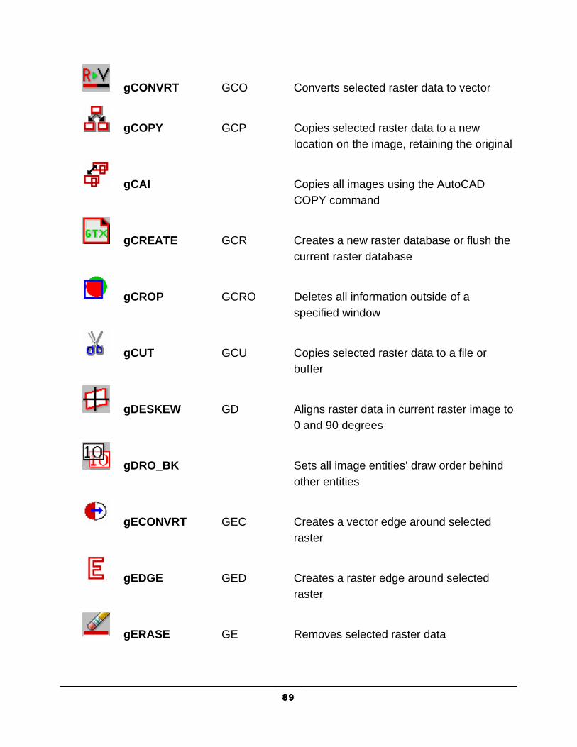
89898989
gCONVRT GCO Converts selected raster data to vector
gCOPY GCP Copies selected raster data to a new location on the image, retaining the original
gCAI Copies all images using the AutoCAD COPY command
gCREATE GCR Creates a new raster database or flush the current raster database
gCROP GCRO Deletes all information outside of a specified window
gCUT GCU Copies selected raster data to a file or buffer
gDESKEW GD Aligns raster data in current raster image to 0 and 90 degrees
gDRO_BK Sets all image entities’ draw order behind other entities
gECONVRT GEC Creates a vector edge around selected raster
gEDGE GED Creates a raster edge around selected raster
gERASE GE Removes selected raster data

90909090
gFRZLAY GFR Freezes the layer of a specified object
gHELP GH Launches the online help
gINFO GI Displays information about the raster database
ImageFrame Configures the AutoCAD Image Frame
ImageTransparency Controls AutoCAD image transparency
gINACTIVE GINA Deactivates the currently active image, freeing memory
gINVERT GIN Reverses the raster foreground and background data Useful for raster scanned from negative images
gISOLAY GISL Freezes all layers except that of a selected object
gJOIN GJO Joins lines
gLINE GLN Draws lines on current raster image
gMIRROR GMI Mirrors selected raster data
gMOVE GM Moves selected raster data

91919191
gMAI Moves all images using the AutoCAD MOVE command
gOFFSET GOFF Creates concentric raster circles, parallel raster lines and parallel raster arcs
gOSR Invokes GTX OSR for doing batch raster-to-vector conversion
gPASTE GP Pastes raster data from a raster file or a buffer created with gCUT
gRAHEAD GRAH Erases “arrowheads” (solids with three points)
gRASTER GRA Converts selected vector entities to raster
gREFLCT GREF Mirrors the entire image in either the X or Y axis, replacing the original image
gRELIMIT GREL Combines trim and extend for lines
gRESIZE GRE Resizes the image entity (Adds or removes pixels without scaling the image entity)
gROTATE GR Rotates selected raster data
gRAI Rotates all images using the AutoCAD ROTATE command

92929292
gREDUCE GRED Reduces a multi-color image to a more manageable number of colors
gRUB GRU Erases raster data under selected vector data
gSAI Scales all images using the AutoCAD SCALE command
gSAVE GSA Saves the raster image
gSCALE GS Scales selected raster data
gSEPARATE GSEP Separates colors to discrete bitonal images
gSETLAY GSL Sets the current layer to that of a specified entity
gSMOOTH GSM Smoothes selected raster. This feature is now available under GTXRaster CAD and higher levels of the software
gSPECKL GSP Perform raster object speckle removal to selectively erase background noise or fill in holes in the raster image
gTCONFIG GTCFG Configures Text Window IOP, Text Line IOP and the gTCONVRT/gTRAIN commands

93939393
gTCONVRT GTC Converts raster text to AutoCAD text entities
gTRACE GT Traces vector lines, arcs, and circles over selected raster geometry (raster is preserved)
gTRAIN GTR Previews and edits text recognition files used by gTCONVRT.
gTRANS_ON Makes all images transparent
gTURN GTU Reorients the work area (and image) by 90, 180 or 270 (-90) degrees
gVECTOR GV Traces raster to vector lines, arcs and circles.
gVSKEW GVS Deskews vector data
gWARP GW Corrects distortions in an image
Raster Picking Options Most commands affect a subset of the raster image. To gMOVE a raster circle, you need to first pick that circle. The GTXRaster CAD series uses Intelligent Object Picking (IOP) to pick raster entities from the drawing as if they were intelligent CAD entities. These options can be typed, found in the GTX Edit>Raster Pick, the toolbar or the screen menu.

94949494
The following list describes each IOP option:
Icon Pick Option
Short Description
ADd ADD Add data to the selection set (after using “remove”)
Remove R Remove selected data from the selection set
ALL ALL Select all raster on the current raster image
AllText Selects (or deselects) all text in the current raster image
Window W Select all raster within a rectangular window
PWindow PW (Polygon Window)
CRossing CR Select connected raster objects that are completely contained by or crossing the edge of a window
PCrossing PC (Polygon Crossing) Select raster that is completely contained by or crossing the edge of a polygon
Inside I Select raster objects completely contained by a window
PInside PI Select connected raster objects that are completely contained by a polygon.
Fence F Select connected raster objects that are intersected by a polyline
Object O Select contiguous raster data within the current view
ARc AR Select raster arcs under a reference arc
2 Pick Circle 2P, 2PC Select raster circle using a 2-point reference circle
CIrcle CI Select raster arcs or a circle under a reference circle
Line L Select raster lines under a reference line
PRevious PR Pick the objects in the previous selection set

95959595
Icon Pick Option
Short Description
Segment S Selects a linear raster segment in both directions from a pick until it stops or finds an acute angle or a branch
TEXTLine TEXTL Select text-sized raster elements that are intersected by a reference line. Separates text from touching raster elements
TEXTWindow TEXTW Select raster text elements that are within a rectangular window. Separates text from touching raster elements
unDer D Pick raster under selected vector objects
Undo U Remove data from the selection set added by the last pick made
View V Select all raster data within the present view
Raster Object Snapping Options The GTXRaster CAD series provides transparent “raster snaps” similar to but independent from AutoCAD object snaps. While using an AutoCAD or GTX command, select Control-Right-mouse button to choose raster snaps from a pop-up menu.
In addition to transparent raster snaps, the GTXRaster CAD series includes the gAUTOSNAP command, enabling AutoCAD’s Endpoint, Intersection, Nearest and Node AutoSnap™ methods within active raster entities. The following table lists each raster snap option.
Icon Name Keyboard Description None rnone Disables previous snap mode settings
Endpoint ‘rend Snaps to the nearest end of a raster entity
Endpoint activates as running snap under AutoCAD’s End AutoSnap™.
Intersection ‘rint Snaps to the intersection of two or more raster entities
Intersection activates as running snap under AutoCAD’s Intersection AutoSnap™.
Nearest ‘rnea Snaps to the centerline of the nearest raster object

96969696
Nearest activates as running snap under AutoCAD’s Nearest AutoSnap™.
Edge ‘redge Snaps to the edge of the nearest raster object.
Edge activates as running snap under AutoCAD’s Node AutoSnap™.
Center ‘rcen Snaps to the center of a circle or arc defined by three raster points
Tangent ‘rtan Snaps to the point that, with the previous point, makes a line tangent to a circle or arc defined by three raster points. The first point defines the side of the circle or arc for the tangent
Midpoint ‘rmid Snaps to the midpoint of a line defined by two raster points
MidArc ‘rmida Snaps to the midpoint of a raster arc defined by the endpoints and a circumference point
Perpendicular ‘rper Snaps to a point where the present entity being drawn will intersect perpendicular to a line defined by two points
Perp-Arc ‘rpera Snaps to the point perpendicular to an arc defined by three raster points
Command Definitions This section defines each command. The AutoCAD variables control the use of dialog boxes or prompts for many commands. FILEDIA controls dialogs for file commands and CMDDIA controls dialogs for other commands. Setting these variables to “1” enables the dialogs. Setting the variables to “0” disables dialogs and causes these commands to use AutoCAD command line prompts.

97979797
gACLEAN Type Menu Availability GACLEAN GACL
GTXEnhance>Auto clean GTXRaster CAD GTXRaster R2V GTXRaster CAD PLUS
Icon:
gACLEAN automatically deskews the image and removes noise and speckles without forming a selection set; it is completely automatic. Another command, GCLEANIOP is interactive, forming a selection set that can be modified before erasing the noise.
Instructions:
Issue the Clean IOP command. The program will automatically deskew the image and delete noise.
NOTE If you are concerned about losing information from your drawing, you may use gCLEANIOP instead

98989898
gACTIVE (Active Image) Type Menu Availability GAC GTX Imaging>Active Image All Products
Icon:
Every raster editing/enhancing command requires an active image to be specified. The gACTIVE command is invoked automatically when there is none specified, so you won’t explicitly invoke this command unless you are working on more than one image at a time and wish to switch from one to another.
gACTIVE sets active images to transparent.
Options:
Number of Images Note: Invoke gINACTIVE to make an active image inactive and save
memory. CLIPPING only masks the DISPLAY of images. When editing a clipped image, the entire image is being edited (selections include clipped portions of an image, but after the edit, the clipping is still active).
The behavior of gACTIVE varies depending on the number of images currently attached to the AutoCAD drawing:
One Image: If there is only one image currently attached, gACTIVE will automatically set it as the active raster image.
Two or More Images: If there are two or more images, a prompt will request that you select the one to edit.
Image Type
gACTIVE behaves differently depending on the number of images attached.
Bi-Tonal: Bi-tonal images are activated quickly and easily.
99999999
Color or Grayscale: Color or grayscale images are reduced to bi-tonal (two colors) before becoming active. The color or grayscale image is not modified; rather, the command generates a bitonal version of the original.

100100100100
gADESKEW Type Menu Availability GAD or GADESKEW GTX Enhance>Auto Deskew
GTXRaster CAD, R2V & GTXRaster CAD PLUS
Icon:
Drawings are often scanned in slightly rotated. gADESKEW straightens a raster image by automatically rotating it to align with the X or Y axis.
Instructions:
1. Select gADESKEW. Deskew Entire Image?
3. The deskew will take place, based on long raster lines found in the margin of the raster image. If no such lines are found, they will not deskew.

101101101101
gARC Type Menu Availability GARC GTX Edit>Draw Arc All Products
Icon:
Draws a raster arc in the current raster image
Instructions:
gARC
Enter or accept line width
Start point:
Select or type the first endpoint.
Middle point:
Select or type a second endpoint.
End point:
Select or type a third endpoint.The arc appears after the third point is specified.
Note: If there is no active image, gACTIVE will be invoked before continuing with gARC. If there is no image attached gCREATE will be invoked to set up an image into which raster line can be drawn.

102102102102
gARRAY
Type Menu Availability GAR or GARRAY GTX Edit>Array
GTXRaster CAD GTXRaster CAD PLUS
Icon:
gARRAY copies raster data in rectangular or polar arrays. When creating a rectangular array, gARRAY arranges multiple copies of the selected raster in rows and columns. When creating a polar array, the command arranges copies of the selected raster placed about a circle.
Instructions:
1. Invoke gARRAY. Select raster <Window>:
2. Select the raster data to be copied. Use any valid raster selection method.
3. Press [RETURN]. Rectangular or Polar array (R/P) <R>:
4. Enter R for rectangular or P for polar.
Rectangular
If using a rectangular array you must specify the number of rows and columns to be copied.
Number of rows (---)<1>:
a. Enter the number of rows you desire. Number of columns (|||)<1>:
b. Enter the number of vertical columns you desire. Unit cell or distance between rows (---):
c. You may enter a vertical distance numerically or draw a “unit cell” representing the distances between rows and columns graphically. If you enter a distance numerically then press [RETURN], you will receive the following prompt:

103103103103
Distance between columns (|||):
d. Enter the distance that will separate the columns. The selected raster is copied. Note: Positive x or y distances places copies to the right or above the
original. Negative distances places them to the left or below the original.
If you drew a unit cell instead of typing a distance, a rectangular box will rubber-band from the anchor point. Drag the box to represent the distance between both the rows and columns. The selected raster is copied.
Polar
If using a polar array you must specify the center point of the array, the number of copies, the angle to fill and whether or not to rotate the raster data as it is copied around the polar array.
Center point of array:
a. Select a point that represents the axis around which all selected data will be copied. Number of items:
b. Enter the number of items that will fill the angle you will specify. Angle to fill (+=ccw,-=cw)<360>:
c. Enter an integer value representing the angle over which the copies will be evenly distributed. Rotate objects as they are copied? <Y>:
d. Respond Y to rotate the objects as they are copied. This will keep the raster objects in the same orientation to the center point as they are copied. Responding N will keep the raster objects in the same orientation as the original raster object selected.
The raster data is copied.

104104104104
gATTACH
Type Menu Availability GA, GATTACH GTX Imaging>Quick Attach All Products
Icon:
gATTACH loads an image into AutoCAD with fewer steps than used in AutoCAD’s IMAGE command.
Instructions:
Select gATTACH.
The gATTACH file dialog will appear.
Select the appropriate file type in the “List Files of Type:” combo-box, select the directory in which the file resides. All files of the indicated type will appear in the “File Name” box. Select the file you wish to load and press OK.
Loading a Raster File
The image is attached at 0,0 and at the orientation specified by the AUTOROTATE configuration parameter.
Raster Resolution
If the GTXRAST.CFG setting is “FILE” the file’s resolution will be used, but if a specific resolution is set in GTXRAST.CFG, it will override that of the file.
Color Images
There is a difference in the way the gATTACH handles & opens color or black & white (binary) images. If you use the gATTACH command to open a 'color image' you will additionally be asked how you wish to pre-process the color image

105105105105
The best command to use depends mainly upon the number of colors that your image has.
gBITONAL
If you wish to automatically reduce a color image down to a simple binary image you can use gBITONAL The gBITONAL command has been optimized to operate on a broad range of color images & works well where an image has a clear-cut distinction between dark & light data.
However, the gBITONAL threshold may not give the exact results that you desire (by including or omitting important data from the binary image). In these instances it may be better to use the gREDUCE & gSEPARATE commands, where you have greater control of the color separation & threshold.
gREDUCE
If you have an image with greater than 256 colors you can firstly use gREDUCE to bring the image down to 256 colors or less.

106106106106
gSEPARATE
For images with colors less that 256 colors, either before or after using reduction, you can use the gSEPARATE command. This allows you to accurately select colors, or groups of colors, & break then out into separate binary color images.
These separate binary images can, if required, be further processed using the full range of GTX capabilities & commands detailed elsewhere in this help file.
For more detailed information about each command's operation refer to the respective gBITONAL, gREDUCE & gSEPARATE section in the 'Command Reference'.
Cancel
Cancel does no pre-processing & just loads the image into AutoCAD. In this state you cannot work on the color image using GTX commands.
.

107107107107
gAUTOSNAP Type Availability Menu
GTXRaster CAD GTXRaster CAD PLUS
GTX Edit>Raster AutoSnap GAS, GASP, GASNAP or GAUTOSNAP
GTXRaster R2V GTX Enhance>Raster AutoSnap
Icon:
gAUTOSNAP enables AutoCAD’s AutoSnap™ options within an active image.
Details:
See “Snapping to Raster” in the Using GTXRaster CAD Series section for more details on using AutoCAD’s AutoSnap™ within raster images.
Instructions:
GAUTOSNAP: <0>,1:
1. Type 1 to raster-enable AutoSnap™.
2. Invoke AutoCAD’s OSNAP command. The dialog includes a Select Settings section.
3. Select the snap modes you wish to enable. The AutoCAD Endpoint, Intersection, Intersection and Node settings activate GTX raster snaps. Because AutoCAD does not provide “Edge” snapping, its Node snap is used to activate running edge raster snap.
AutoCAD Object Snap GTX Raster Snap Endpoint Endpoint Intersection Intersection Nearest Nearest Node Edge
Select OK.
The aperture box will appear around the crosshairs and the marker will snap to raster features.

108108108108
Note: AutoSnap™ uses glyphs (symbols) to represent the snap type. GTX running snaps use ToolTip labels to identify the snap being used. Snaps work instantaneously even though the ToolTips appear after a short delay.

109109109109
gBITONAL
Type Menu Availability gBITONAL, gBIT GTX Convert>
Convert Image to Bitonal All Products
Icon:
gBITONAL automatically reduces a color image to a binary (1-bit) image.
The gBITONAL command only works when you have one or more color (or greyscale) images loaded.
Instructions:
Issue the gBITONAL command. The program will then automatically reduce a multi-color image to a binary image.
If you have no color/greyscale images loaded & you activate the command you will get an error telling you that you don’t have a suitable image for gBITONAL to work on.
If you have more than one color/greyscale image loaded you will be offered a dialog box to select the image you wish make bitonal.
Notes: gBITONAL only works if you have a color (or greyscale) image loaded. On large color images the gBITONAL command can take some time to process. The gBITONAL algorithm has been optimized to operate on a broad range of color images. As such the command works well where an image has a clear-cut distinction between dark & light data.

110110110110
However, the gBITONAL threshold may not give the exact results that you desire (by including or omitting important data from the binary image). In these instances it may be better to use the gSEPARATE command, where you have greater control of the color separation & threshold.

111111111111
gBURN Type Menu Availability GBU or GBURN GTX Convert>Burn All to Raster GTXRaster CAD
GTXRaster R2V GTXRaster CAD PLUS
Icon:
gBURN converts all vector entities into raster data with a designated line width. Note: The raster database must be established before gBURN can be
used. The database can be established either by loading a raster file or by using gCREATE. If the database has not been established, you will see a message and gCREATE will be invoked automatically. Only entities within the raster limits can be rasterized! Those outside the limits will be ignored or erased. When entities are partially outside, the part inside is rasterized; the part outside is erased. All vector entities will be deleted when you use this command!
Options:
Width Options
Table Use the width settings according to color as set in the Width Table
Fixed Type in a value or select the width graphically using Box or Pick.
Instructions:
Dialog
1. Invoke gBURN. The following dialog will appear.
2. To specify line width you can a) enter a Fixed line width, b) specify it graphically by drawing a Box or by using Pick to select raster in the

112112112112
drawing of the desired width, or c) use a Table to correlate the colors of vectors to raster line widths.
Fixed Line Width:
a. Select the Fixed radio button. Type the raster width to be used (in AutoCAD units, not pixels), or use the Pick or Box option to graphically specify the width.
Using Box:
a. Select the Box button. Select first corner of box:
b. Select a point. Select opposite corner of box:
c. As you move the cursor, a rubber-banding rectangle appears with one corner at the point selected. Move the cursor until the box is the desired width and the length exceeds the width. Select the point.
The best way to use this feature is to pick a point on the edge of an existing horizontal or vertical raster line and stretch the box along the line. You can then easily match the width. The length of the rectangle can be any size that is longer than the width as the smallest side is used as the width measurement. A reference rectangle is used instead of a square to make it easier to see. As soon as the second point has been selected, the rasterization takes place.
Using Pick
a. Select Pick. Select raster <WIDTH>d
b. Select a piece of raster data of the desired raster width. The width of the selected raster will be entered in the “Fixed” text box.
Using the LineWidth Configuration Table:
a. Select the Table radio button and the Table Setup button. The LineWidth Configuration Table appears, correlating AutoCAD color numbers and line widths expressed in current units.
113113113113
b. To change the width associated with a particular AutoCAD color, select that ACAD Color row. Enter the value in the Width text field. Select OK to close the dialog or select another row to change its width.
Line Width Configuration Dialog Enter width <.XX>:
c. Enter the value for the width in the units being used and press [RETURN]. The Width Table will reflect the changes.
d. Select another color number to change its width or press [0] and [RETURN] to continue the command.
The entities will be changed to raster with the widths defined by their colors.
The highlighted entities will be converted to raster. Some residual vector markings overlay the raster until you redraw the image.
AutoCAD Prompts
1. Invoke gBURN. Raster width Box/Pick/<Table>/.01:
2. There are three ways to respond to this prompt. You can 1) type in a value as the width to be used for all vector lines to be rasterized for plotting; 2) use the LineWidth Configuration Table to correlate AutoCAD color numbers with line widths; or 3) use the Box or Pick options to specify a standard linewidth graphically (as described above).
Fixed Line Width:
a. You can type in a value (in mm or inch) as the width to be used for all the vector lines to be rasterized. The value in parentheses is the default value or one previously used. If you enter a value it will remain the default line width during this editing session. Note: If you defined the width previously in this session with a typed
value or the “box” option, that value will appear as the default. You can press [RETURN] to accept this value or enter a number to represent the new width. The selected entities will all be converted to raster with the designated width.
Using the LineWidth Configuration Table:

114114114114
a. If you type in “T” or “Table”, the LineWidth Configuration Table appears. The listing correlates AutoCAD color numbers and line widths expressed in current units.
b. If you defined the width previously in this session with a typed value or the “box” option, that value will appear as the default. You can press [RETURN] to accept this value or enter a number to represent the new width. The selected entities will all be converted to raster of the designated width. Note: The original default option is to use the Width Table set up by
colors. This allows you to set different widths for entities being rasterized according to their color. If you press [RETURN] or [T], the Width Table will be displayed. The widths will be in inches or millimeters according to the unit set in GTXRAST.CFG.
LINEWIDTH CONFIGURATION TABLE
To change a line-width for different AutoCAD colors, enter thenumber for the entry. When you are satisfied with the settings,enter 0 to continue.
AutoCAD Color #s Width in Inches0. To Continue1. Color 1 (Red) .012. Color 2 (Yellow) .013. Color 3 (Green) .024. Color 4 (Cyan) .025. Color 5 (Blue) .036. Color 6 (Magenta) .037. Color 7 (White) .048. Color 8 .089. Color 21 .0910. Color 23 .1011. Color 30 .1112. Color 41 .1213. Color 63 .1314. Color 153 .1415. Color 191 .1516. Color 161 .16Enter the color number (1-16) of the width to change<0>:
c. Enter the number and press [RETURN] Enter width <.XX>:
d. Enter the value for the width in the units being used and press [RETURN]. The Width Table will reflect the changes.
e. Select another color number to change its width or press [0] and [RETURN] to continue the command.
115115115115
Note: The width settings you change will remain in effect until you change them or you exit AutoCAD.
The vectors will be burned to raster with the table’s widths. Note: Polylines and other non-filled entities that have a width attribute
will be drawn with the AutoCAD width attribute. Rasterization of certain entities may take a while to process. Rasterizing text and ellipses takes longer than lines, for instance. Select less data at a time to improve rasterization speeds. You may need to zoom in to see line styles. This command does not work for 3-D entities.

116116116116
gCALIKE Type Menu Availability GCA or GCALIKE GTX VClean>Calike GTXRaster R2V
GTXRaster CAD PLUS
Icon:
gCALIKE modifies the radius of circles or arcs to a specified radius or to match that of a selected circle or arc.
Options:
The circles can be changed in terms of a Reference circle or arc, a specified Radius or Diameter.
Instructions:
Select objects:
1. Select one or more circles and/or arcs that you will want to set to identical radii.
Select reference circle or arc:
2. Choose a circle or arc with the desired radius.
Enter Diameter <Radius> <#.##>:
3. The reference object’s radius will appear in the angle brackets. A rubber banding line stretches from the center of the reference object to the cursor. Press [RETURN] to accept the value, graphically select with the left mouse button the desired radius, type a new desired radius value, or type D and then enter a new diameter.

117117117117
gCELEV Type Menu Availability GCE or GCELEV GTX VClean>Contour Elevation GTXRaster R2V
GTXRaster CAD PLUS
Icon:
gCELEV sets the elevation of a series of PLINE objects in increments.
Instructions:
Set the base or starting elevation.
Set the Contour Interval – the increments by which elevation is changed.
Press OK.
Stop/<Pick Contour>:
Select the polyline to assign the starting elevation.
Stop/<Pick Contour>:
Select the polyline to assign consequent elevations.
When done, type S.

118118118118
gCHANGE Type Menu Availability GCH or GCHANGE GTX Edit>Change GTXRaster CAD
GTXRaster CAD PLUS
Icon:
gCHANGE stretches raster lines, arcs and circles. Change the radius of an arc by moving its circumference and endpoint. Change the radius of a circle by moving its circumference. Change the length and orientation of a line by moving one endpoint.
This command also merges or smoothes fragmented and irregular lines or arcs. To smooth, choose the raster entity and redraw it without changing its geometry. To smooth or merge entire sections of a drawing, use the gSMOOTH command. In the following illustrations, dashed lines portray rubber-banding lines.
Options:
Object Type Options
Line Select a line to be changed.
Arc Select an arc to be changed.
Circle Select a circle to be changed.
Instructions:
1. Select gCHANGE. Select raster <LINE>:
2. The original default is “line”. If you want to select another type of object, select it from the menu or type the first letter of the name.
Using Line
119119119119
a. Select a point on the raster line to serve as the endpoint that will NOT change. Then select a point to indicate the rest of the line that will be altered. The raster line will be highlighted and a rubber-banding reference line will appear, attached at the first point used to pick the line (If the first point was outside the raster line, the endpoint closest to that point is selected). Select new endpoint:
Note: If you choose points to change a raster line drawn in a broken or dashed line style, all the segments will be selected, but the new line will be redrawn as a smoothed, solid line. Turn on the Ortho Mode ON if you want to change lines so they are perfectly horizontal or vertical or so they snap to a specified angle.
b. Move the cursor. The reference line will rubber band as it follows the cursor. Press [SELECT] to select the new point where the line should end. The reference line will disappear and the raster line will be redrawn at the new orientation and length.
Using Arc
a. Select the endpoint that will NOT change. Then select a point on the circumference of the arc and the other endpoint of the arc. These three points define the raster arc and the selected arc will be highlighted. Select new circumference point:
b. You will see a rubber-banding line extending from the first endpoint selected. Select a point to be on the circumference of the new arc. Select new endpoint:
c. The rubber-banding line will be attached at the second point. Select the endpoint for the new arc in any of the usual ways. The raster arc will be redrawn through the three points. If the original arc was in several pieces, they will be selected but the new arc will be solid.
Using Circle
a. Select the “circle” option from the menu. Select point on circumference of circle:
b. Specify the raster circle by selecting three points on the circumference. After the raster circle has been selected, it will be highlighted. A rubber-banding line from the center of the circle will appear.

121212120000
Enter circle radius:
c. Enter a value in current units or select a point to indicate the radius of the new circle. The circle will be redrawn with the original center point and the new radius. Note: If the original circle was broken into arcs or drawn in a dashed line
style, they will be selected but the new circle will be unbroken.

121121121121
gCHGLAY Type Menu Availability GCHGLAY GCHL
GTX VClean>Change Layer GTXRaster CAD PLUS GTXRaster R2V
Icon:
gCHGLAY changes the layer of objects to that of a specified object.
Instructions: Select Objects to Change Layer:
1. Select the objects you want to move to a destination layer. Dialog/<Select object on NEW layer>:
2. Either type D to select a layer or to define a new layer, or select a sample object that is already residing on the desired destination layer.
If you selected a sample object, the selected objects are moved to the same layer as the sample. If you selected dialog, continue reading the following instructions:
The Manual Layer Selection dialog appears.
3. Select the destination layer name from the list or select New Layer to define a new destination layer for the selected objects.
4. When done, select OK.
The selected objects are moved to the specified layer.

122122122122
gCIRCLE Type Menu Availability GCIRCLE GC
GTXEdit>Draw Circle ALL Products
Icon:
Draws a raster circle in the current raster image
Instructions:
gCIRCLE
Center Point:
Select (or type) the centerpoint of the circle.
Radius [Diameter]:
Select (or type) the radius, or type "D" and then specify the Diameter.
The circle appears after the radius or diameter is specified.
Note: If there is no active image, gACTIVE will be invoked before continuing with gCIRCLE. If there is no image attached gCREATE will be invoked to set up an image into which raster line can be drawn.

123123123123
gCLEANIOP Type Menu Availability GCLEANIOP GTXEnhance>Clean IOP GTXRaster CAD, R2V &
GTXRaster CAD PLUS
Icon:
gCLEANIOP deskews the image and removes noise and speckles. gCLEANIOP creates a selection set of all noise. You can use ADD and REMOVE in combination with other IOP methods to refine the selection set. When finished, the command deletes the highlighted raster.
Instructions:
The image automatically deskews and noise is highlighted. Select Raster <WINDOW>:
Add or remove raster using standard IOP methods (see Raster Picking Options on page 93). When done adding and removing raster, press [RETURN].

124124124124
gCONCEN Type Menu Availability gCONCEN or GCONC GTX VClean>Concen GTXRaster R2V
GTXRaster CAD PLUS
Icon:
gCONCEN moves circles and arcs to be concentric about a location or about the centerpoint of a specified circle or arc.
Instructions: Select Objects:
1. Select one or more circles or arcs Pick point/<Select circle/arc>:
2. Select another arc or circle about which the previously selected objects should become concentric. Alternatively, type P and select the location itself.
The selected objects are moved so their centerpoints align about the centerpoint of the target object or about the indicated location.
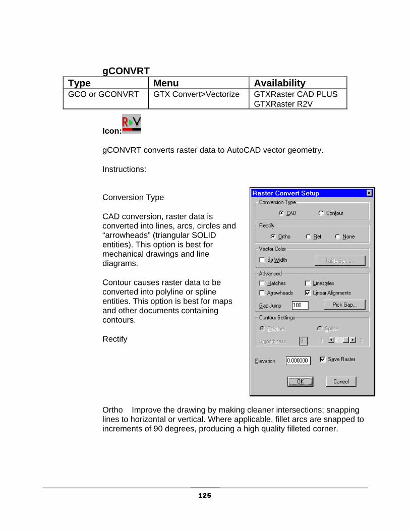
125125125125
gCONVRT Type Menu Availability GCO or GCONVRT GTX Convert>Vectorize GTXRaster CAD PLUS
GTXRaster R2V
Icon:
gCONVRT converts raster data to AutoCAD vector geometry.
Instructions:
Conversion Type
CAD conversion, raster data is converted into lines, arcs, circles and “arrowheads” (triangular SOLID entities). This option is best for mechanical drawings and line diagrams.
Contour causes raster data to be converted into polyline or spline entities. This option is best for maps and other documents containing contours.
Rectify
Ortho Improve the drawing by making cleaner intersections; snapping lines to horizontal or vertical. Where applicable, fillet arcs are snapped to increments of 90 degrees, producing a high quality filleted corner.

126126126126
Reference snaps lines that are close to a specified reference angle to that angle. Parallel lines at this angle separated by a distance close to the offset distance are snapped to that distance.
1. Select Reference. First point for snap angle:
2. Select the first point for the angular line. Second point for snap angle:
3. Select the second point to define the angle. Reference angle <XX.XXXXX>:
4. You can type in a new value for the angle or press [RETURN] if it is satisfactory. You cannot redefine it by selecting points.
Parallel alignment offset <0.0>:
5. This value determines the distance between the imaginary grid lines parallel to the given reference angle. Type in a value in current drawing units. Using the (0.0) value which is always the default means no grid snapping for this angle.
First point for snap angle:
6. You can define another reference angle and grid or press [RETURN] if you don’t want to use another one. When you are finished defining the angles, press [RETURN]. The command then continues as above.
Note: If you use the Reference Angle option, orthogonal rectification will not occur automatically. However, you can enter “0” and “90” reference angles to achieve orthogonal rectification.
None converts raster exactly as it appears without any rectification.
Vector Color
AutoCAD vector entities don’t have any width. You can preserve information stored in the line width of the raster image; you can assign a color to vectors resulting from different line widths.
By Width causes the values in the line-width configuration table will be used to determine the color of the vector entities. Table Setup displays the table and values can be changed if desired. If several colors are given the same width value, only the lowest number color will be used for that line width.

127127127127
1. Select the No Widths check box to render resulting vectors in the current AutoCAD layer’s color or select the Table Setup button to color-code resulting vectors for up to 16 different line widths.
Line Width Configuration Table Dialog
2. Click on the color to modify a color’s width value. Enter the new value in the Width input window at the lower right corner. Note: If you set your
AutoCAD display options so that the background of the screen is white, the Line Width Configuration Table’s “white” color (color #7) will refer to black vectors.
3. Select another color to change or click OK to exit the Line Width Configuration dialog.
Leaving By Width inactive causes resulting vectors to inherit the color and linestyle of their layers.
Hatches
When this is active, vectors generated from hatched areas will be isolated on their own AutoCAD layer. The name for this layer is established by the Hatch_Layer_Name configuration parameter in GTXRAST.CFG. You can create this layer in advance in your drawing template and give it a color if you always want hatched data to appear the same. Hatch angle? <0.000>/Pick:
1. Type the hatch angle or type P to select two points designating the angle.
Parallel alignment offset <0,0>

128128128128
2. Type the distance between hatches or select two points designating the distance.
Hatch angle? <45.000>/Pick:
When done, press [RETURN]. Parallel alignment offset <0,0>
Press [RETURN] again.
Linestyles
When this is active, lines that appear to have regular breaks in the raster image will be isolated on their own AutoCAD layer. The name for this layer is established by the Linestyle_Layer_Name configuration parameter in GTXRAST.CFG. As with Hatch_Layer_Name, you can create this layer in advance in your drawing template and give it a color and linestyle if you always want hatched data to appear the same.
Arrowheads
Controls whether arrowheads (3-sided solids) are generated during CAD type conversion.
Linear alignment
Linear Alignment causes broken lines to be merged into unbroken lines as they are vectorized. This is used to convert dashed geometry as a single entity (then the entities can be moved to a dashed AutoCAD layer). If this box is empty, collinear geometry with gaps or breaks will be vectorized without closing the gaps. The gap is established by the Gap Jump setting.
Gap Jump
Sets the distance in pixels for Linear Alignment to jump when combining multiple collinear lines into single lines (as in recognizing dashed linestyles). This can be set by manually entering the distance or by selecting Pick Gap and then graphically showing a gap distance.
Other Options
Save Raster preserves raster data after converting it to vector. If this box is empty, the raster will be erased after conversion.
129129129129
Elevation sets the elevation at which resulting vectors will be created. The default value is 0. To create contours at different elevation, set this value before converting raster to vector.
Elevation
Set the Elevation to the level at which resulting vectors should be created (normally you want this to be 0).
When all parameters are set as desired, click OK to launch the conversion process.
Prompt Mode
gCONVRT also works exclusively with AutoCAD prompts when the CMDDIA variable is set to 0.

130130130130
gCOPY Type Menu Availability GCP or GCOPY GTX Edit>Copy GTXRaster CAD
GTXRaster CAD PLUS
Icon:
gCOPY copies raster data from one location to another location in the image entity.
Options:
Movement Options
Base Point Indicate the offset distance for the copy by selecting two points. Note: Turn the ORTHO Mode ON to place copies in a perfectly horizontal,
vertical, or specified direction from the last position.
Displacement Enter X and Y offset values to indicate copy placements.
Instructions:
1. Select gCOPY. Select raster <WINDOW>:
2. Select the raster to be copied. The selected raster will be highlighted.
3. When all of the raster to be copied is highlighted, press [RETURN]. Base point or displacement:
There are several ways to respond to this prompt. To use the default option, either select a reference point or type in how far over the selected data should be copied. Since the system does not know whether X,Y value typed in this is the base point or the displacement distance, the response to the second point clarifies this.
Using Base Point
a. Select a base point either by using the cursor or by typing the coordinates. This will be a reference point for the copy process.

131131131131
Second point of displacement:
b. A rubber-banding line will appear attached at the base point. Select a second point to define the relative distance and angle for placement of the copy. The copy will appear in the designated location in the display raster color. The original raster will be un-highlighted. The command will terminate.
Using Displacement
a. At the “base point or displacement” prompt, type in the X and Y value for the displacement in the same format used to enter coordinates. You will see the same prompt as above. Second point of displacement:
b. Press [RETURN] to indicate that the original entry was the displacement. The raster data you selected will be copied to its new location in the main raster color. The original raster will be un-highlighted. The command will terminate.

132132132132
Copy All Images Type Menu Availability gCAI GTX Imaging>Modify Images>Copy All Images GTXRaster Tools
GTXRaster CAD GTXRaster CAD PLUS GTXRaster R2V
Icon:
Copy All Images invokes AutoCAD COPY command on all image entities.

133133133133
gCREATE Type Menu Availability GCR or GCREATE GTX Imaging>Create All Products
Icon:
gCREATE establishes an unnamed raster image entity on the current AutoCAD layer. The raster data can be modified within the limits, which can be changed later using the gRESIZE command.
The MaxNumPixels configuration parameter limits the number of pixels allowed in a new raster image. The default value is: MaxNumPixels=973440000
which at 400 dpi could generate an image measuring 78” x 78”.
Instructions:
1. Select gCREATE. Enter raster resolution DPI <200>:
2. Enter a positive integer. select lower left corner of raster limits <0.000,0.000>:
3. Normally, you enter “0,0” for this value. However, you can select any point either by typing coordinates or selecting it graphically.
Select upper right corner of raster limits:
4. A rubber-banding box will appear attached at the first point. Select the point for the upper right corner either with coordinates or graphically.
Warning: When creating a new raster image in a hybrid environment, consider the drawing’s scale. Raster images will normally be about the same size as paper media. Create images at “paper” size and then scale them against your vector data. You don’t want to create a raster image the size of a house or a map - it will take a long time if it works at all!
5. The program will check whether there is sufficient memory for the work area you designate. If not, you will get an error message.

134134134134
gCROP Type Menu Availability GCRO or GCROP GTX Enhance>Crop All Products
Icon:
gCROP Deletes all raster data outside of a specified rectangular window. For instance, you may use it to get rid of “dirty” edges or an unwanted frame.
Instructions:
1. Select the gCROP command. Select first corner of window:
2. Select a point for one corner of the window. Select opposite corner of window:
3. A rectangular window will rubber-band from the first point selected. Position it to include all the raster data you want to save. Press [SELECT] to select the point.
Note: If your drawing is skewed or rotated, use gDESKEW first. To reduce the raster limits by eliminating the outside area, use gRESIZE or use the gCUT command to create a new file.
The raster data outside the window will disappear. The raster limits stay the same.
135135135135
gCUT Type Menu Availability GCU or GCUT GTX Edit>Cut GTXRaster CAD
GTXRaster CAD PLUS
Icon:
gCUT copies raster data from the active image entity to a raster file or to memory. The default filename is set in the configuration file. Note: 1. Raster data cut from images is oriented relative to the raster
file’s coordinate system. When cutting raster data from a rotated image entity, the raster is not necessarily saved as displayed within AutoCAD. Also, when pasting raster data into a rotated image, the raster data appears at the image entity’s native rotation. 2. If the “raster limits” box does not enclose all of the highlighted raster data, the data outside the rectangle will not be saved in the file. 3. If the rectangle does not fall entirely within the raster limits, the limits will be used instead of the point(s) selected. If you want to save the file with a format other than the one specified in the GTXRAST.CFG file, type in the extension that defines that format.
Options:
Mode Options
Copy Copy the data and retain it on the screen.
Erase Copy the data and erase it from the drawing.
Destination Options
File Copy the data to a raster file.
Buffer Copy the data to a temporary buffer (to be gPASTE-d later).
Instructions:
1. Select gCUT. Command: gCUTMode <Copy>/Erase:

136136136136
2. The default value is in brackets. Press [RETURN] to select the default or select the desired mode from the menu or by entering its abbreviation.
Select raster <WINDOW>:
3. Select the raster data.
4. Press [RETURN] when all the raster data to be saved in the new file has been highlighted. You will next be prompted to define the image limits.
Select lower left corner of raster limits:
5. Type in the coordinates for the point or position the cursor and press [SELECT]. A rubber-banding box will appear attached at the point.
Select upper right corner of raster limits:
6. Select the point for the upper right corner of the limits. The two points you have selected are stored as the upper and lower limits of the image.
File/<Buffer>:
7. Enter B to copy the data to a temporary raster buffer. The selected data within the rectangle will be copied to a raster buffer for later insertion using gPASTE. Enter F to save the selected data to a raster file (Continue with step 8).
Dialogs:
a. After specifying F or File, gCUT will save the selected data to a raster file. gCUT will display the SAVE Raster File dialog.
Enter the desired file name and select the appropriate path for the new file.
b. To change the default file type, select the scroll box labelled “List Files of Type:” and select the desired file format.
c. The file name entered does not need to include the extension. The file type extension displayed in the List Files of Type: box will be used.
d. Click OK to return to the drawing editor.

137137137137
Prompts:
a. After specifying F or File, gCUT will save the selected data to a raster file. gCUT will display the following prompts: Enter raster file name <cut_data.ext>:
b. The default file name is “cut_data” with the extension indicated in the GTXRAST.CFG file. If you have previously used gCUT, the name of that file will be the default shown in brackets. Accept the default file name by pressing [RETURN] or type a new name for the raster file and press [RETURN].
If you do not include the extension, the format and extension set in the GTXRAST.CFG by “RasterFormat” and “RasterSaveExt” entries will be used. If no path is indicated, the file is saved using the path defined in the GTXRAST.CFG “RasterPath” entry. If no path was defined, it is saved in the current directory.
c. If a file already exists with the same name you typed as a new name, you will be asked whether to replace it. If you respond “yes”, the new file will overwrite the old one. If you accept the default, “No”, you will again be prompted for a raster file name. The request is repeated until an acceptable name is entered or you cancel the command without saving a file.
d. When a file has been saved, the highlighting will disappear. If the “erase” mode was selected, the highlighted data will also disappear. Otherwise the raster data remains as it was before the command was invoked. Raster file FILENAME.EXT saved.

138138138138
gDESKEW Type Menu Availability GD or GDESKEW GTX Enhance>Deskew All Products
Icon:
Drawings are often scanned in slightly rotated. gDESKEW straightens selected raster by rotating it to align with the X or Y axis.
The gADESKEW (Auto Deskew) command may be faster and easier with drawings that have titleblocks.
The deskew uses reference line that is rotated to horizontal or vertical (whichever is closer). Pick points as far apart as possible. Use transparent zoom or raster snapping features to draw the reference line precisely.
The lower left corner is used as the rotation point.
Processing time depends on image size, and resolution, and available memory.
Instructions:
1. Select gDESKEW. Command: gDESKEWThis command could fail in limited memory situationsDo you want to save the raster image first? Yes/<No>:
2. If you have adequate memory for the file you are using or have already saved the data, press [RETURN]. Otherwise, it is a good idea to respond “Yes”. GTXRaster CAD will then invoke gSAVE, you will save the data and gDESKEW will continue.
Select raster <WINDOW>:
3. Select the raster data to deskew. If deskewing the entire drawing, type: ALL. Press [RETURN].
Select one end of reference line:
4. Select a point on a raster line that should be perfectly horizontal or vertical. A rubber-banding reference line will extend from it to the cursor.

139139139139
Select other end of reference line:
5. Move the cursor to the second point on the line and select it. The deskew will take place, based on the reference line you indicated. You will see a message: De-skewing XX.XXXXXX degrees.
Do you wish to displace deskewed raster? Y/<N>:
6. If the raster is located correctly, press [RETURN]. The command will be completed. If you wish to move the deskewed raster, type: Y.
Base point or displacement:
There are two ways to respond. You can either select the first of two points that will show the movement graphically or type in the offset values in the form X,Y. Since the system does not know whether the X,Y value typed in is the base point or the displacement distance, the response to the second prompt clarifies this.
Using Base Point
1. Select the reference point for the moving process. Second point of displacement:
Note: 1. If you skew the same file several times the raster data could become distorted. If this happens, re-load the raster image and deskew it again using gDESKEW once. 2. If the image needs to be rotated more than 5 degrees you should re-scan the drawing. Deskewing the entire image more than a few degrees can distort the raster data. 3. Large files may take several minutes to complete the operation. Using transparent zoom or the “end” or “int” raster snapping methods can help you more accurately pick your reference line.
2. A rubber-banding line will appear attached at the base point. Select a second point to define the relative distance and angle for the new placement of the deskewed raster. It will appear in the designated location. The command will be completed.
Using Displacement
1. Type in the X and Y values for the displacement in the same format used to enter coordinates. You will see the same prompt as above. Second point of displacement:

140140140140
2. Press [RETURN] in response to the prompt to indicate that the original entry was the displacement. The deskewed raster will appear in the new location.

141141141141
DrawOrder Back Type Menu AvailabilityGDRO_BK GTX Imaging>Modify>Send Images to Back All Products
Icon:
DrawOrder Back Moves all raster image entities’ draworder to back using AutoCAD’s DrawOrder command.

142142142142
gECONVRT Type Menu Availability GEC or GECONVRT
GTX Convert>Vectorize Edge GTXRaster R2V GTXRaster CAD PLUS
Icon:
gECONVRT converts raster data to AutoCAD vector geometry.
Options:
Contour When checked, raster contours are converted into polyline entities, which are good for designating contours. When this checkbox is empty, raster data is converted into lines, arcs, and circles.
Save Raster Retains raster after conversion to vector. If this box is empty, the raster is erased during conversion.
Elevation Sets the elevation at which resulting vectors will be created. The default value is 0. To create contours at different elevation, set this value before converting raster to vector.
Instructions:
1. Invoke gECONVRT. Specify raster <WINDOW>:
2. Select the desired raster and press [RETURN]. The Edge Convert Setup dialog will appear:
Width Recognition
The edge of a solid raster area has no width, so this option is disabled. Proceed to the conversion type.
CAD or Contour Conversion:

143143143143
3. Checking the Contour box will cause lines and polylines to be generated. Leaving this box un-checked will cause only lines, arcs and circles to be generated.
a. If the Contour option is checked, the Polyline Smooth Index input window will contain a value between 1 and 9. A value of 1 would follow the contours least smoothly, and 9 results in the closest match to the contour.
With lower resolution images you may want to choose values lower than 8 or 9 so that the polylines don’t follow the square contours of individual pixels!
4. Set the Elevation to the desired level at which resulting vectors will be created.
5. Set Save Raster to your preference
6. Select OK to start the conversion.

144144144144
gEDGE Type Menu Availability GED or GEDGE GTX Enhance>Edge All Products
Icon:
gEDGE removes the inside of solid raster regions, leaving only the edge. Removes all raster except a single pixel width contour around the edge of selected raster data.
Instructions:
Command Dialog:
1. Invoke gEDGE. Select raster <WINDOW>:
2. Select the raster you wish to “hollow out”. Press [RETURN].
3. The insides of the raster are erased, leaving a 1-pixel edge around the outside.

145145145145
gERASE Type Menu Availability GE or GERASE GTX Edit>Erase All Products
Icon:
gERASE removes selected raster data from the drawing.
Instructions:
1. Invoke gERASE. Select raster <WINDOW>:
2. Select the raster you want to remove.
3. When all the raster data to be removed is highlighted, press [RETURN]. The selected raster is then erased.
146146146146
gFRZLAY Type Menu Availability GFR or GFRZLAY
GTX VClean>Freeze Layer GTXRaster R2V GTXRaster CAD PLUS
Icon:
gFRZLAY freezes the layer of a selected object.
Instructions:
Dialog/<Select object>:
Choose an object residing on the layer you wish to freeze or type D to use the dialog.
Object:
The layer of the selected object becomes frozen.
Dialog:
A dialog appears. Choose the layer or layers to freeze and select OK.
147147147147
gHELP Type Menu Availability GH or GHELP GTX Imaging>Help All Products
Icon:
gHELP starts the GTXRaster CAD Help file. The Help window functions as any other Windows application Help file, including “search for keyword” capabilities.
The Help file can also be executed from the GTXRaster CAD Help icon in the GTX program folder.
For more information on available sources of help, refer to the Introduction.
148148148148
Image Frame Type Menu Availability ImageFrame GTX Imaging>Modify Images>Image Frame All Products
Icon:
ImageFrame sets frames for all image entities to on or off. Sets the AutoCAD ImageFrame variable.

149149149149
Image Transparency Type Menu Availability Transparency GTX Imaging>Modify Images>Image Transparency
On All Products
Icon:
Transparency makes all images transparent when selected from the Imaging toolbar. Otherwise lets you set the transparency mode for selected images.

150150150150
gINACTIVE Type Menu Availability GINA or GINACTIVE
GTX Imaging>Deactivate Image All Products
Icon:
gINACTIVE deactivates the active image entity, freeing memory. In order to edit the image you must reinvoke gACTIVE and choose the image.

151151151151
gINFO Type Menu Availability GI or GINFO GTX Imaging>Info All Products
Icon:
gINFO displays details about the current raster image and the software license. It includes the default values for raster file name and format, as well as the resolution, the raster limits and data extents (in current drawing units). The file name and format will be that of the last raster file loaded or saved.
Instructions:
1. Select gINFO. You will see a listing on the text screen display similar to the following. The values shown are sample values only.
Resolution: Shows the resolution of the current raster database in terms of dots per inch (DPI). This value is obtained from the resolution from the file unless overridden by the GTXRAST.CFG Resolution setting or by a resolution established using gCREATE.
Raster data limits: Defines the rectangular area indicating the size of the present raster image, including bounding white space, set with gCREATE or gRESIZE or by the limits of the raster drawing that was loaded. The values are given in current drawing units.
Raster data extents: Defines smallest rectangular area that can enclose the raster data in terms of AutoCAD units. It is defined by the X and Y coordinates of the lower left corner, followed by the X and Y coordinates of the upper right corner of the rectangle. The extents determine where raster data is currently drawn.
Drawing limits: Defines the AutoCAD drawing limits.
Source FileName: The name of the raster file to which the image refers.
Active FileName: The filename to which gSAVE will save.

152152152152
Raster File type: This reflects the format of the last raster file saved with gSAVE or the setting in GTXRAST.CFG if no file has been saved yet.
Undo store size: Number of raster undo’s being recorded.
Image modified? Flag identifying whether image has been changed since the last save (TRUE or FALSE).
Version: Shows GTX program, version number, and ARX version of the GTX program that is running.

153153153153
gINVERT Type Menu Availability GIN or GINVERT GTX Enhance>Invert All Products
Icon:
gINVERT Reverses the background and main raster colors of the current raster image. Use it on files scanned in reverse (light on dark). This does not just invert the display of an image - it truly inverts the raster image itself.
Instructions:
The color of the background and the color of the data will be switched. You can then edit the raster data with any of the GTXRaster CAD commands.
Undo gINVERT by invoking the command again.

154154154154
gISOLAY Type Menu Availability GISL or GISOLAY
GTX VClean>Isolate Layer GTXRaster R2V GTXRaster CAD PLUS
Icon:
gISOLAY freezes all layers except that of the selected object, effectively isolating its layer.
Instructions: Select objects:
Select objects on the layer or layers you want to isolate.
Press [RETURN].
The layers of the objects chosen in step 1 are isolated by freezing all other layers.

155155155155
gJOIN Type Menu Availability GJO or GJOIN GTX VClean>Join GTXRaster R2V
GTXRaster CAD PLUS
Icon:
gJOIN joins vector lines together.
Instructions:
Select line startpoint.
Select the endpoint of the line you wish to join with another line. Select object
Select the first line (whose endpoint you selected). Select object
Continue selecting lines until all lines you wish to join have been selected.
Press [RETURN]
All selected lines are merged into one line.

156156156156
gLINE Type Menu Availability GLN or GLINE GTX Edit>Draw Line All Products
Icon:
gLINE draws a raster line in the current raster image.
Instructions: From point:
Select or type the first endpoint. To point:
Select or type the other endpoint.
The command continues, allowing you to continue entering point coordinates. To point:
Note: If there is no active image, gACTIVE will be invoked before continuing with gLINE. If there is no image attached, gCREATE will be invoked to set up an image into which the raster line can be drawn.
Enter the endpoint for the next line or press [RETURN] to end the command.

157157157157
gMIRROR Type Menu Availability GMI or GMIRROR GTX Edit>Mirror
GTXRaster CAD GTXRaster CAD PLUS
Icon:
gMIRROR creates a mirror image of selected raster data. This is different from reflect which mirrors the entire current raster image. You will define a line for the data to be mirrored across. You may either retain or discard the original data.
Instructions:
1. Select gMIRROR. Select raster <WINDOW>:
2. Select the raster data to be mirrored. The selected raster will be highlighted.
3. When you have selected all the items to be mirrored, press [RETURN].
First point of mirror line:
4. Select a point for the start of the reference line. Second point:
5. Select another point to define the reference line. Delete old objects? Yes/<No>
6. Press [RETURN] to preserve the original raster geometry. If you only want to keep the new mirrored data, enter Y.

158158158158
gMOVE Type Menu Availability GM or GMOVE GTX Edit>Move
GTXRaster CAD GTXRaster CAD PLUS
Icon:
Function:
gMOVE moves selected raster data from one area to another on the drawing. The displacement points define the relative distance and angle that the items will be moved from the original position. Note: Turn ORTHO mode ON to move objects in perfectly horizontal or
vertical directions.
Options:
Base point Indicate the offset distance for the copy by selecting two points.
Displacement Enter X and Y offset values to indicate copy placement.
Instructions:
1. Invoke gMOVE. Select raster <WINDOW>:
2. Select the raster data to be moved. The selected raster will be highlighted.
3. When you have selected all the items to be moved, press [RETURN].
Base point or displacement:
There are two ways to respond. You can either select the first of two points that will show the movement graphically or type in the offset values in the form X,Y. Since the system does not know whether the X,Y value typed in is the base point or the displacement distance, the response to the second prompt clarifies this.
Using Base Point

159159159159
a. Select a point either by using the cursor or by typing the coordinates. This will be a reference point for the moving process. Base point or displacement:Second point of displacement:
b. A rubber-banding line will appear attached at the base point. Select a second point to define the relative distance and angle for the new placement of the data. The data will appear in the designated location in the main raster color. The raster will disappear from the original location. The command will be terminated.
Using Displacement
a. Type in the X and Y values for the displacement in the same format used to enter coordinates. You will see the same prompt as above. Second point of displacement:
Press [RETURN] in response to the prompt to indicate that the original entry was the displacement. The raster data you selected will disappear from the original location and be displayed in the new location in the raster color.

160160160160
Move All Images Type Menu Availability gMAI GTX Imaging>Modify Images>Move All Images All Products
Icon:
Move All Images invokes AutoCAD Move command on all image entities.

161161161161
gOFFSET Type Menu Availability gOFFSET GOFF
GTX Edit>Offset GTXRaster CAD GTXRaster CAD PLUS
Icon:
gOFFSET creates a copy of a selected line, arc, or circle parallel or symmetrical to the original. This command is similar to the AutoCAD OFFSET command.
Instructions:
Having prepared an image for editing,
1. Invoke gOFFSET. Offset distance or Through <Through>:
2. Either enter a distance or use the mouse to indicate the distance through which copies will be offset.
Select raster <LINE>:
3. At this point you enter “C” for circle, “A” for arc, or click two points on a raster line.
Line
Click two points along the raster line.
Arc/Circle
Click three points along the circumference of the arc or circle.
Offset Side to offset?
4. Click a point to one side of the line, arc or circle. (You can click inside or outside a circle).

162162162162
A copy of the original entity will be placed at the specified offset distance on the indicated side.

163163163163
gOSR Type Menu Availability GOSR GTX Convert>OSR Batch Convert GTXRaster R2V
GTXRaster CAD PLUS
Icon:
Function:
gOSR launches the GTX OSR batch vectorization program. This requires that you have a license for either GTXRaster CAD PLUS or GTXRaster R2V, as well as a license for GTX OSR.
Instructions:
1. Invoke gOSR. If the directory containing GTX OSR (C:\GTX_OSR) is on the system path, then it will run.
2. If the directory is not in the system path, a file dialog will be displayed.
3. Locate the GTX OSR executable and select Open. GTX OSR will run.
Refer to Appendix 4: GTX OSR V5.0, on page 247 for further details.
164164164164
gPASTE Type Menu Availability GP or GPASTE GTX Edit>Paste GTXRaster CAD
GTXRaster CAD PLUS
Icon:
gPASTE inserts a saved raster image at a specified location on the graphics screen. You can use this command to insert saved raster onto an existing image or onto a blank graphics screen to create a new image. The image may be scaled or rotated as it is placed. The default values for file format and name will be taken from the GTXRAST.CFG file or the current database, but can be overridden. Raster files of any acceptable format can be used.
1: Raster data cut from images is oriented relative to the raster file’s coordinate system. When cutting raster data from a rotated image entity, the raster is not necessarily saved as displayed within AutoCAD. Also, when pasting raster data into a rotated image, the raster data appears at the image entity’s native rotation.
2: If there is no active image, gACTIVE will be invoked before continuing with gPASTE. If there is no image attached, gCREATE will be invoked to set up an image into which raster data can be pasted.
Options:
Source Options:
File Insert raster data from a raster file.
Buffer Insert raster data from a temporary buffer (previously created with gCUT).
Paste Options:
Move Move the pasted data to a different location.
Rotate Specify the desired orientation (angle) of the image.
Scale Specify the factors by which to change the X and Y dimensions.

165165165165
Fit A “Scale” option that allows you to show the scale graphically.
Instructions:
1. Invoke the gPASTE command. File/<Buffer>:
2. Type F to paste data from a raster file. Type B, Buffer or [RETURN] if it is the default as shown above to paste data from a temporary buffer (created with gCUT).
Pasting from a File:
gPASTE will determine the raster file you wish to paste. If CMDDIA is set to 1, the following dialog will appear:
Enter the desired file name and select the appropriate path for the new file.
If CMDDIA is set to 0, gPASTE will issue the following prompt: Command: GPASTEEnter raster file name <cut_data.ext>:
Type the name of the raster file that you want to paste. “Cut_data” or the last file pasted is the default, shown in brackets. If no path is entered, the program looks for the file in the current directory, then for the ACAD path, then for the DOS path.
Pasting from a Buffer
gPASTE will paste raster data from a buffer only if you previously performed a gCUT to that buffer.
After determining the source of the raster data to be pasted, the following prompt will appear: Insertion point <0.0000,0.0000>:
3. Select the point where the lower left corner of the file should be placed. The raster data of the file will appear at that location in the
166166166166
main raster color. The gPASTE menu will replace the GTXRAST menu.
Loading raster -- filename.ext ...Move/Rotate/Scale
4. If you are satisfied with the default settings and the present location of the raster, press [RETURN] to exit from the command. To change the location, rotation or scale, select the desired option. Options can be selected in any order and any number of times until you press [RETURN] to exit from the command.
The same data can be selected for further raster editing with the “previous” option of the editing command. For instance, if you want to have more than one copy of the pasted data at the same size and orientation, you can select gCOPY and “previous”.
Using Move
1. Select “Move” by entering “m” or selecting “Move” from the menu. The pasted data will be highlighted. You will be prompted to indicate a base point for the move. Base point or displacement:
2. Select a reference point. This may be a significant point such as the center of a cross.
Second point of displacement:
A rubber-band line will extend from the base point.
3. Select a second point to indicate the distance and angle that the base point should move. The raster data will move to the new location and be un-highlighted. The reference line disappears.
Move/Rotate/Scale:
4. You can continue to select options or press [RETURN] to terminate the command.
Using Rotate
1. Enter “r” or select “Rotate” from the menu to change the orientation of the reference box. The pasted data will be highlighted. Base point:
2. Select a point for the center of rotation.
167167167167
Rotation Angle <0.0>/Reference:
3. A rubber-band line will extend from the base point. The rotation point is the lower left corner of the box. The rotation is counter-clockwise from the X-axis if a positive angle is entered.
There are several ways to respond. You can accept the default angle by pressing [RETURN] or use either of the two options. The default angle, initially zero degrees, reflects the value used for a previous gPASTE operation.
Rotation Angle
Using rotation angle, you can specify the angle with reference to the X-axis by typing in a value (in degrees) or by rubber-banding the reference line.
When you designate the angle by either method, the raster will be redrawn in the new orientation.
Using Reference Angle
Using reference angle, you must enter “r” or select “Reference” from the menu. You then indicate a different base line (not the X-axis) for the graphic angle.
Reference angle <0.0>:
� You can either enter a degree value to define the new base line in relation to the X-axis or you can define it graphically by selecting the first point for the base line.
Reference angle <0.0>: Second point:
� Select the second point for the base line. New angle:
� Indicate the final position for the new base line by entering a value. You can also indicate the rotation angle graphically if you chose the original base point (the center of rotation) as the first point of the new base line. The selected data will rotate the same amount. The angle of rotation will actually be the angle between the reference line positions.
For example, if the desired rotation would bring a certain line to a vertical position, you could draw the base line over that line and then

168168168168
type “90” for the new angle. The default angle then will be 90 minus the angle of the base line.
� As soon as the rotation angle has been specified, the highlighted data will rotate about the base point. The highlighting will be removed.
Move/Rotate/Scale
You can select another option to change or press [RETURN] to terminate the command.
Using Scale
1. If you enter “s” or select “Scale” from the menu, the pasted data will be highlighted and you can change the size of the image. The default value is initially set to X=1, Y=1. Base point:
2. Select the point about which the raster will be scaled. This point will not change its location. It also serves as the first point for the scale rectangle if you use the graphic method of scaling.
Scale factors <1.0,1.0>/Fit:
3. The data is scaled from the base point. You can type the numerical values by which to scale the X- and Y- dimensions or select “Fit” and change the height and width graphically.
If you select “Fit”, you will be prompted to select the original size. Select original size:
Select two corners of a box representing the size of the original image.
Select new size:
Draw the window to show the relative size of the desired image to the reference box. The data that filled the original rectangle will be enlarged or compressed to fit into the new rectangle. The X and Y dimensions can be different.
After you indicate the scale by either method, the pasted data is redrawn at the new size and un-highlighted. Move/Rotate/Scale:
4. You can select another option to change or press [RETURN] to terminate the command. You can further adjust the image after you

169169169169
have placed it with the “previous” option in the desired command (gMOVE, gSCALE, etc.).

170170170170
gRAHEAD Type Menu Availability GRAH or GRAHEAD GTX VClean>Remove Arrow Heads GTXRaster R2V
GTXRaster CAD PLUS
Icon:
Function:
gRAHEAD erases “arrowheads” (three-sided solids).
Instructions: Filter Arrow heads - All/<Select objects>:
Type A for all or press [RETURN] to select a group of objects
If you typed A, then all 3-sided solids are erased. If you chose to select objects, the following prompt is shown: Select objects:
Window or pick objects. Press [RETURN] when done. arrowheads are highlighted.
Press [RETURN] to erase them.

171171171171
gRASTER Type Menu Availability GRA or GRASTER GTX Convert>Rasterize GTXRaster CAD
GTXRaster R2V GTXRaster CAD PLUS
Icon:
gRASTER converts selected vector entities into raster data with a designated line width. The AutoCAD line style will be preserved.
Options:
Width Options
Table Use the width settings according to color as set in the Width Table
Box Define a value graphically to be used for the width of the vector selected to be converted to raster.
Value Type in a value in inches or millimeters to use for the width of the vector selected to be converted to raster.
Note: 1. If there is no active image, gACTIVE
will be invoked before continuing with gRASTER. If there is no image attached, gCREATE will be invoked to set up an image into which raster data can be created.
2. Only entities within the raster limits can be rasterized. Those selected outside the limits will be ignored or erased. When entities are partially outside, the part inside is rasterized; the part outside is erased.

172172172172
Instructions:
Dialog
1. Invoke gRASTER. The following prompt will appear: Select objects:
2. Select the vector entities to be converted. When all entities to be converted are highlighted, press [RETURN]. The Rasterize Setup dialog will appear.
3. To specify line width, you can enter a Fixed line width, specify it graphically by drawing a Box or use a Table of vector color-to-raster line width correlations.
Fixed Line Width:
Select the Fixed radio button. Type a value (in mm or inch) as the width to be used for all the vector lines to be rasterized, or use the value in the Fixed Width text field. If you enter a value it will remain the default line width during this editing session.
Note: If you defined the width previously in this session with a typed value or the “box” option, that value will appear as the default.
Using the LineWidth Configuration Table:
a. Select the Table radio button and the Table Setup button. The LineWidth Configuration Table appears, correlating AutoCAD color numbers and line widths expressed in current units.
b. To change the width associated with a particular AutoCAD color, select that ACAD Color row. Enter the value in the Width text field. Select OK to close the dialog or select another row to change its width. Enter width <.XX>:

173173173173
c. Enter the value for the width in the units being used and press [RETURN]. The Width Table will reflect the changes.
d. Select another color number to change its width or press [0] and [RETURN] to continue the command.
The entities will be changed to raster with the widths defined by their colors.
Using Box
a. Select Box. Select first corner of box:
b. Select a point. Select opposite corner of box:
c. As you move the cursor, a rubber-banding rectangle appears with one corner at the point selected. Move the cursor until the box is the desired width and the length exceeds the width. Select the point.
The best way to use this feature is to pick a point on the edge of an existing horizontal or vertical raster line and stretch the box along the line. You can then easily match the width. The length of the rectangle can be any size that is longer than the width as the smallest side is used as the width measurement. A reference rectangle is used instead of a square to make it easier to see. As soon as the second point has been selected, the rasterization takes place. Note: The next time you use this command, the value of the width you
used will be displayed as the default fixed linewidth.
The highlighted entities will be converted to raster. Some residual vector markings overlay the raster until you redraw the image.
Using Pick
a. Select a vector entity
b. Select the Pick option Select raster <width>:
c. Next select a raster entity or enter a width

174174174174
A dialog box will appear with a fixed width value of the raster entity selected.
d. Select OK
The vector entity selected will be converted to line width of the previous raster that was selected using the Pick command.
AutoCAD Prompts
1. Select gRASTER. Select objects:
2. Select the vector entities to be converted. When all entities to be converted are highlighted, press [RETURN].
Raster width Box/<Table>/.01:
3. There are three ways to respond to this prompt. You can 1) type in a value as the width to be used for all vector lines to be rasterized for plotting; 2) use the LineWidth Configuration Table to correlate AutoCAD color numbers with line widths; or 3) use the Box option to specify a standard linewidth graphically.
Fixed Line Width:
a. You can type in a value (in mm or inch) as the width to be used for all the vector lines to be rasterized. The value in parentheses is the default value or one previously used. If you enter a value it will remain the default line width during this editing session. Note: If you defined the width earlier in the session, that value will
appear as the default. You can press [RETURN] to accept this value or enter a number to represent the new width. The selected entities will all be converted to raster with the designated width.
Using the LineWidth Configuration Table:
a. If you type in “T” or “Table”, the LineWidth Configuration Table appears. The listing correlates AutoCAD color numbers and line widths expressed in current units.

175175175175
b. If you defined the width previously in this session with a typed value or the “box” option, that value will appear as the default. You can press [RETURN] to accept this value or enter a number to represent the new width. The selected entities will all be converted to raster of the designated width. Note: The original default option is to use the Width Table set up by
colors. This allows you to set different widths for entities being rasterized according to their color. If you press [RETURN] or [T], the Width Table will be displayed. The widths will be in inches or millimeters according to the unit set in GTXRAST.CFG.
c. Enter the number and press [RETURN] Enter width <.XX>:
d. Enter the value for the width in the units being used and press [RETURN]. The Width Table will reflect the changes.
e. Select another color number to change its width or press [0] and [RETURN] to continue the command. Note: The width settings you change will remain in effect until you
change them or you exit AutoCAD.
The entities will be changed to raster with the widths defined by their colors.
Using Box
a. At the prompt, type “B” or select “Box” from the menu. Select first corner of box:
b. Select a point. Select opposite corner of box:
c. As you move the cursor, a rubber-banding rectangle appears with one corner at the point selected. Move the cursor until the box is the desired width and the length exceeds the width. Select the point.

176176176176
The best way to use this feature is to pick a point on the edge of an existing horizontal or vertical raster line and stretch the box along the line. You can then easily match the width. The length of the rectangle can be any size that is longer than the width as the smallest side is used as the width measurement. A reference rectangle is used instead of a square to make it easier to see. As soon as the second point has been selected, the rasterization takes place.
The highlighted entities will be converted to raster. Some residual vector markings overlay the raster until you redraw the image.
Note: 1. The next time you use gRASTER, the value of the width you used will
be the default fixed line width. 2. If the width value is less than 1 pixel, the raster width will automatically
be reset to 1 pixel, regardless of the way the width was set. 3. Polylines and other non-filled entities that have a width attribute will be
drawn with the AutoCAD width attribute. 4. Rasterization of certain entities may take a while to process.
Rasterizing text and ellipses takes longer than lines, for instance. Select less data at a time to improve rasterization speeds.
5. gRASTER does not convert 3-D entities
CALS Plotter Driver
An alternative method for rasterizing vector data is to use the Raster File Format HDI plotter driver. This can be configured using the Autodesk Plotter Manager from the Windows Control Panel.

177177177177
gREDUCE Type Menu Availability gREDUCE gRED
GTX CONVERT> Reduce Color Image
All Products
Icon:
gREDUCE reduces the number of colors in an image to a more manageable number of colors (between 4 to 256 colors).
The gREDUCE command only works when you have one or more color (or grayscale) images loaded.
Instructions:
Invoke the gREDUCE command.
If you have no color/grayscale images loaded & you will get an error telling you that you don’t have a suitable image for gREDUCE to work on.
If you have more than one color/greyscale image loaded you will be offered the ‘Image selection’ dialog box. You can then either select the image by name or you can pick it interactively using the ‘Select Image on Screen’ button.
Once the Image has been selected the system will display the color reduction dialog. You can select the numbers of colors you wish to reduce to from a preset list in the range of between 4 to 256 colors.
Or you can specify the exact number of colors.

178178178178
Or you can reduce to a bitonal image.
Notes: gREDUCE only works if you have a color (or greyscale) image loaded. You cannot use the command to increase the number of colors.

179179179179
gREFLCT Type Menu Availability GREF or gREFLCT GTX Enhance>Reflect All Products
Icon:
gREFLCT reflects the raster within an image about the X or Y axis. This command can be useful if an image was scanned through the back of transparent media.
Instructions:
1. Select gREFLCT. Select axis to mirror data about <Xaxis>/Yaxis:
2. Select “X” or “Y” or press [RETURN] to select the default value. The entire image is flipped about the chosen axis and the raster limits are rotated to the new orientation.

180180180180
gRELIMIT Type Menu Availability GREL or GRELIMIT GTX VClean>Relimit GTXRaster R2V
GTXRaster CAD PLUS
Icon:
gRELIMIT combines the effects of AutoCAD TRIM and EXTEND commands for vector lines
Instructions: Select line end point:
1. AutoCAD’s End AutoSnap becomes enabled to help select endpoints. Select the end of the line you want to trim or extend.
Select Object:
2. Select the boundary line.
The line will lengthen or shorten to meet the boundary.
If the line cannot shorten or lengthen to meet the boundary, the following message is displayed: Object does not intersect an edge.

181181181181
gRESIZE Type Menu Availability GRE or GRESIZE GTX Enhance>Resize All Products
Icon:
gRESIZE changes the size of the raster work area. You can increase the dimensions in both positive and negative directions. This is useful to accommodate pasting in additional raster files, scaling up the drawing, or making edits that would move data beyond the existing limits. You can also reduce the work area to reduce memory requirements; for instance, when the actual data you need occupies only a small portion of the work area.
Instructions:
1. Select gRESIZE. This command could fail in limited memory situationsDo you want to save the raster image first? Yes/<No>:
2. If you have not recently saved your data, respond “Yes”. You will be prompted for a file name and then returned to the command.
Select lower left corner of raster limits <X.XXX,X.XXX>:
3. Select a point with the mouse or type in the coordinates for the point to be the lower left corner of the work area. Negative numbers are acceptable.
Select upper right corner of raster limits:
4. Select a point with the mouse or type in the coordinates for the point to be the upper right corner of the work area. Make sure that all the existing raster data is enclosed in the resulting window. Any raster data not included will be eliminated from the database.
Lines marking the raster work area move to the new boundaries. Existing data retains the same coordinates as before. Warning: When resizing an image, consider the drawing’s scale. Raster
images will normally be about the same size as paper media. Ensure your image remains within a normal “paper” size and then scale it against your vector data. You don’t want to create a raster image the size of a house or a map - it will take a long time if it works at all!

182182182182
gROTATE Type Menu Availability GR or GROTATE GTX Edit>Rotate GTXRaster CAD
GTXRaster CAD PLUS
Icon:
gROTATE rotates selected raster data. You will define the center point and a rotation angle to specify the new orientation for the data. The rotation angle may be selected by entering a value or by picking two points to indicate the angle graphically. gROTATE can also be used to “deskew” a specified section of a drawing.
Options:
Rotation Angle Specify the rotation angle with respect to the X axis.
Reference Angle Draw a new base line and indicate the desired angle for this line.
Instructions:
1. Select gROTATE. Select raster <WINDOW>:
2. Select the raster data to be rotated. When everything you want to be rotated is highlighted, press [RETURN] to continue the command.
Base point:
3. Select a point on the entity to be used as the center point for the rotation process. The entity will turn about this “anchor” point as it rotates. It will also be used as the base point for a graphic representation of the rotation angle.
Rotation angle <0.0>/Reference:
4. There are several ways to respond to this prompt. You can enter the default value, a new rotation angle, or use reference angles to graphically designate the rotation.
Using the Default Angle

183183183183
a. The default angle, initially zero degrees, reflects the value used for a previous gROTATE operation. You can accept the default angle by pressing [RETURN]. Delete old objects Yes/<No>:
Using Rotation Angle
a. You can specify the angle with reference to the X axis by typing in a value (in degrees) or by rubber banding the reference line.
b. When you designate the angle by either method, the raster will be redrawn in the new orientation.
Using Reference Angle
a. Enter “R” or select “Reference” from the menu to use a different base line (not the X axis) for the graphic angle. Reference angle <0.0>:
b. You can either enter a degree value to define the new base line or define it graphically by selecting a point. If you select a point, you will be prompted for the second point. Reference angle <0.0>: Second point:
Select the second point to define the line that should be rotated to a particular angle. New angle:
c. Type in the value for the angle the new base line should take. The selected data will rotate the same amount. The angle of rotation will actually be the angle between the reference line positions. For example, if the rotation should bring a certain line to a vertical position, you could draw the base line over that line and then type “90” for the new angle. The default angle will then be 90 minus the angle of the base line.
5. Respond “yes” if you do not want to retain the original data in addition to the rotated copy.
Note: 1. If raster data is placed so that it is outside of the set raster drawing
limits, the portion outside the drawing limits will be lost. If this happens, use UNDO, use gRESIZE to extend the raster limits as necessary, then use gROTATE to rotate the data. Nothing will be lost because all raster is within the new raster limits.

184184184184
2. Rotating raster data may distort it somewhat. The “line”, “arc”, and “circle” intelligent raster object picking methods may not work on raster data that has been rotated several times.
3. gROTATE can rotate raster right off the image. To rotate an entire raster image 90 degrees, rotate the image entity using the ROTATE command, or use gTURN so that the image is automatically resized.
4. Positive values rotate raster in a counter-clockwise direction.
As soon as the rotation angle has been defined by whatever method is used, the highlighted data will rotate as specified about the base point. The command terminates.

185185185185
Rotate All Images Type Menu Availability gRAI GTX Imaging>Modify Images>Rotate All Images All Products
Icon:
Rotate All Images invokes AutoCAD Rotate command on all image entities.

186186186186
gRUB Type Menu Availability GRU or GRUB GTX Edit>Rub All Products
Icon:
gRUB erases raster data after it has been converted or traced to vector entities. You select the vector entities overlying the raster that is to be erased. This lets you use the raster to evaluate the conversion and then erase it easily.
Instructions:
1. Select gRUB. Select objects:
2. Select the vector entities over the raster to be erased. When all the desired entities are highlighted, press [RETURN]. You will see a message indicating the percent of rub completed.
Note: The width at which gRUB erases is determined by the linewidth configuration table. Automatically generated polylines have no actual width, so they are not very effective for erasing underlying raster. gERASE can be more effective in this situation.

187187187187
gSAVE Type Menu Availability GSA or GSAVE GTX Imaging>Save All Products
Icon:
gSAVE saves changes made to a raster image.
A filename can be up to 256 characters long. If the extension is not included, the default raster format and its extension (such as “.RNL”, “.RLC”, or “.CG4”) will be used.
TIFF subformats (uncompressed, Version 6 tiled, etc.) default to the TIFFFORMAT setting in GTXRAST.CFG.
Instructions:
1. Invoke gSAVE. The SAVE Raster File dialog appears:
2. Select the output format from the List Files of Type box. Enter the File Name and press OK.
3. If the file name already exists, you will be prompted to overwrite the file or cancel the save.
The drawing is saved.
Renaming an Image
If you saved the image to a new name, note that the image entity still points to the originally attached raster file. If you want the drawing to point to the new filename you must do the following:
1. Select Insert>Raster Image... to invoke the AutoCAD IMAGE command.

188188188188
2. Select the GTXARCH image. Above under the Saved Path column you can see the original raster filename. At the bottom of the dialog you can see an “Image Found At” text box, which points at the recently saved filename.
3. Select Save Path. This tells AutoCAD that you want the changed filename as the one to which the image points.
Note: 1. The lower left corner of the drawing raster limits is set as the insertion
point to be used when the file is loaded or pasted. 2. Always save when leaving for any length of time and before loading
new files. If performing many tasks on a single drawing, it is a good idea to save the files periodically.
3. Select OK.
Saving Color Images
There is a difference in the way the gSAVE operates depending upon if you are saving a color or black & white (binary) image. Color images have a more restricted number of file saving formats.
Supported Color file formats.
When working with color images in GTX you can only save in
.tif (uncompressed TIFF),
.bmp (Uncompressed Bitmap),
.png (Portable Network Graphics),
.tga (Taga),.flc & fli (Autodesk FLIC) &
.pcx (PC Paintbrush) formats.
Also, if you originally loaded a .jpg (JFIF JPEG) file you will additionally be offered the option of saving in .jpg (JPEG) format.

189189189189
gSCALE Type Menu Availability GS or GSCALE GTX Edit>Scale GTXRaster CAD
GTXRaster CAD PLUS
Icon:
gSCALE changes the size of raster geometry within an image entity. You may scale the data about a reference point by entering X axis and Y axis scaling factors or you may scale the raster data graphically.
Instructions:
1. Select gSCALE. Select raster <WINDOW>:
2. Select the raster data to be scaled. When all of the data to be scaled is highlighted, press [RETURN].
Base point:
3. Select a point near the data selected. This point is the reference point to scale the entities about (it will not change its location). It also serves as the first point for the scale rectangle if you use the graphic method of scaling.
Scale factors<1.0,1.0>/Fit:
The value in the brackets is the default value, either the initial default of 1.0,1.0 (scale by 1 in both X and Y directions) or any values previously used with the gSCALE command.
4. There are several ways to respond to the prompt. You can use the default value or enter the numerical scaling factors for X and Y. You can also indicate the size graphically be selecting “Fit”.
Using the Default Scaling Factors Scale factors<1.0,1.0>/Fit:
a. The default scaling values reflect the scale factors used for a previous gSCALE operation or 1.0,1.0 if the command has not been used. You can accept the default scale factors by pressing [RETURN].
Entering Numerical Scaling Factors

190190190190
Scale factors<1.0,1.0>/Fit:
a. Enter two values separated by a comma to indicate the X and Y scale factors respectively. To enlarge the image, enter scale factors greater than 1. To shrink the image, enter scale factors between 0 and 1 (Entering “2,2” doubles each dimension and increases the area by a factor of 4. Entering “.5,.5” cuts each dimension in half and decreases the image to 1/4 its original size.)
Using “Fit” Scale factors<1.0,1.0>/Fit:
a. After selecting the base point, select “Fit” from the menu or enter “F”. A rubber-banding box anchored at the base point will appear. Select original size:
b. Rubber-band a reference rectangle from the base point representing the original size of the raster data being scaled. Select new size:
c. Rubber-band a new reference rectangle from the base point representing the new size of the raster data. The “Fit” option generates scale factors based on the size ratio between the reference rectangles. Note: 1. gSCALE can scale raster data right outside the image entity, and the
data is lost! To avoid this, choose the base point to avoid rotating the data outside the limits of the image.
2. After scaling, you can easily re-select the rotated data and reposition it with gMOVE “previous” if necessary - this even works if the rotated data overlaps with preexisting raster.
3. To expand the image, save the file and then use gRESIZE to enlarge the raster work area.
4. Scaling a raster image with different X and Y factors will cause raster arcs and circles to become elliptical. The resulting shapes cannot be selected using the intelligent raster object “arc” and “circle” picking methods.
5. The data is scaled to the dimensions indicated by the scaling factors. The command is terminated.

191191191191
Scale All Images Type Menu Availability gSAI GTX Imaging>Modify Images>Scale All Images All Products
Icon:
Scale All Images invokes AutoCAD Scale command on all image entities.

192192192192
gSEPARATE Type Menu Availability gSEPARATE gSEP
GTX CONVERT> Separate Color image
All Products
Icon:
gSEPARATE separates out individual colors, or selected groups of colors from a color image, & reduces them to a single binary (1 bit) image. The command can separate out to multiple binary images with each run of the command
The gSEPARATE command only works when you have one or more color (or grayscale) images loaded.
Instructions:
Invoke the gSEPARATE command.
If you have no color/grayscale images loaded & you will get an error telling you that you don’t have a suitable image for gSEPARATE to work on.
If you have more than one color/greyscale image loaded you will be offered the ‘Image selection’ dialog box. You can then either select the image by name or you can pick it interactively using the ‘Select Image on Screen’ button.
Once the Image has been selected the system will display the ‘Assign Image Layers’ dialog.

193193193193
You can enter the number of binary images you wish to create (between 1 to 256 images).
The binary images created can be assigned to different layers. The layering naming can be controlled by selecting one of three options:
1) Use current ACAD Layer. In this instance the binary images will be put on the current AutoCAD layer.
2) Use User defined image name as Acad layer name. This option will use the layer name to create a new layer with that name & the image will be placed upon that layer.
3) Select from existing Acad Layers. This prompts the user to select the layer from the existing list of defined layers, for every new binary image created.
Next you can select the file format for the new binary images. Click on the down arrow to see & select the image format.
Select NEXT to move to the Color Separation dialog.

194194194194
You can rename your binary image & layer in the top left hand corner of the dialog. By default the image names are numbers 1,2,3 etc. Highlight the layer number & you can enter a new name in the box above. Then select RENAME to change the image name. You can also add new images at this stage by selecting the NEW button.
You can now move onto select the colors for a particular binary image.

195195195195
Firstly highlight the image name you wish to work on. Then using the cursor ‘drag & drop’ the required colors from the left (Available) payne into the right (Assigned) payne. You can pick the colors individually or in blocks. To select a block of colors hold down the left mouse button over the group of colors you wish to select.
Dialog operation instructions are:
- Edit image name, click Rename button
- Select Acad Layer if applicable
- Left mouse click to select colors
- Left mouse drag to select multiple colors
- Right mouse click to display color properties
- Switch to next image
- Repeat above steps
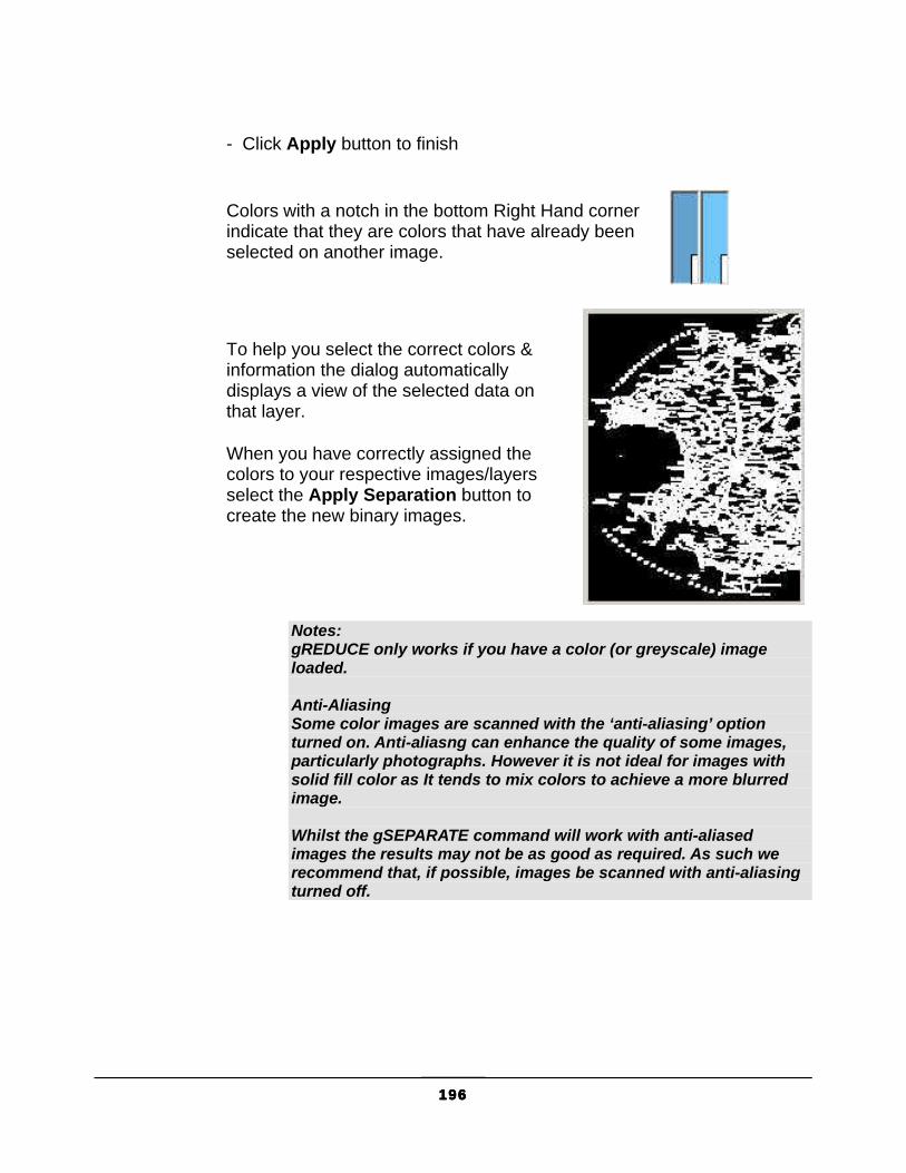
196196196196
- Click Apply button to finish
Colors with a notch in the bottom Right Hand corner indicate that they are colors that have already been selected on another image.
To help you select the correct colors & information the dialog automatically displays a view of the selected data on that layer.
When you have correctly assigned the colors to your respective images/layers select the Apply Separation button to create the new binary images.
Notes: gREDUCE only works if you have a color (or greyscale) image loaded. Anti-Aliasing Some color images are scanned with the ‘anti-aliasing’ option turned on. Anti-aliasng can enhance the quality of some images, particularly photographs. However it is not ideal for images with solid fill color as It tends to mix colors to achieve a more blurred image. Whilst the gSEPARATE command will work with anti-aliased images the results may not be as good as required. As such we recommend that, if possible, images be scanned with anti-aliasing turned off.

197197197197
gSETLAY Type Menu Availability GSETLAY GSL
GTX VClean>Set Layer GTXRaster R2V GTXRaster CAD PLUS
Icon:
gSETLAY sets the current layer to that of a specified entity
Instructions: Dialog/<Select object>:
1. Select an object whose layer you wish to make current or type D to use the dialog.
Select Object:
The selected object’s layer becomes current.
The following dialog appears:
Select the layer you wish to make current and press OK or select New Layer.
Pressing OK makes the selected layer current.
Selecting New starts the New Layer Creation dialog:
Type the name and choose the color for a new dialog. Press OK when done.
The new layer becomes current.

198198198198
gSMOOTH Type Menu Availability GSM or gSMOOTH GTX Enhance>Smooth GTXRaster CAD
GTXRaster R2V GTXRaster CAD PLUS
Icon:
gSMOOTH smoothes raster objects in a selected portion of the raster data. gSMOOTH can also make raster lines orthogonal or parallel to a specified angle, combine fragmented raster lines. gSMOOTH can smooth raster linewidth to a fixed value or snap raster linewidth to a series of user-defined linewidths. By smoothing raster, gSMOOTH can reduce the file size by up to 30 percent.
Instructions:
Dialog:
Conversion Type indicates the type of raster-to-vector conversion being used to smooth the raster. CAD interprets raster as lines, arcs and circles. Contour interprets raster as polyline contours.
Ortho improves the drawing by snapping lines to horizontal or vertical.
None smoothes the data exactly as it appears without any rectification.
Reference snaps lines close to any reference angle to that angle and parallel lines at this angle separated by a distance close to the offset distance will snap to the offset distance.
Line Width Options

199199199199
Box defines a value graphically to be used for the width of the data selected to be smoothed.
Value applies a literal value to use for the width of the selected data to be smoothed. Note: Be sure to enter values in current units (mm or inches), not in the
current AutoCAD Drawing Unit. The graphically defined width will also be translated to mm or inches when it appears as the default.
Average smoothes raster geometry to an average of that segment’s width.
Table snaps the lines to the nearest value listed in the Width Table.
AutoCAD Prompts
1. Select gSMOOTH. Select raster <WINDOW>:
2. Select the raster to be smoothed. When all the data to be converted is highlighted, press [RETURN].
Width Box/Table/<Average>/0.01:
3. There are several ways to respond to the prompt. You can enter a value to be the fixed line width for all selected data or you can select this value graphically with the “Box” option. You can average each raster element’s width or you can set up a Table of LineWidths to which raster elements are snapped.
Using a Fixed Line Width
a. The value shown in the prompt is the value used last or the one set for RasterWidth in the configuration file. To accept the default value, press [RETURN]. Type a number that represents the width in current size units.
Using Box
a. At the prompt, type “B” or select “Box” from the menu. Select first corner of box:
b. Select a point on the edge of a horizontal or vertical raster line. Select opposite corner of box:
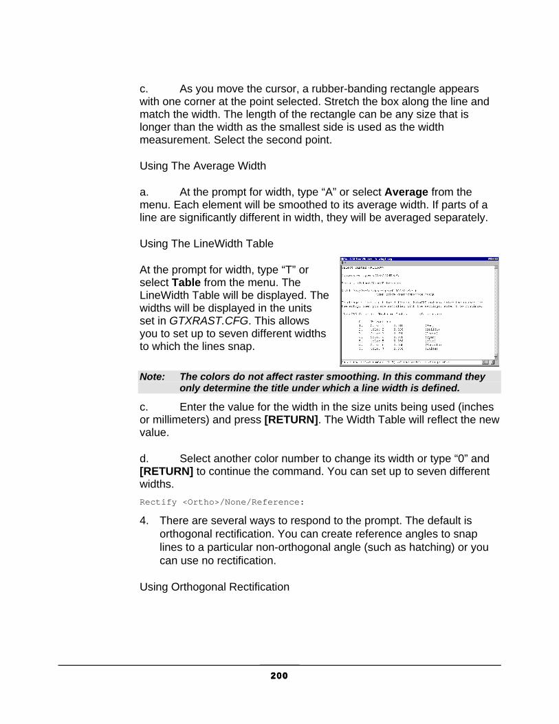
200200200200
c. As you move the cursor, a rubber-banding rectangle appears with one corner at the point selected. Stretch the box along the line and match the width. The length of the rectangle can be any size that is longer than the width as the smallest side is used as the width measurement. Select the second point.
Using The Average Width
a. At the prompt for width, type “A” or select Average from the menu. Each element will be smoothed to its average width. If parts of a line are significantly different in width, they will be averaged separately.
Using The LineWidth Table
At the prompt for width, type “T” or select Table from the menu. The LineWidth Table will be displayed. The widths will be displayed in the units set in GTXRAST.CFG. This allows you to set up to seven different widths to which the lines snap.
Note: The colors do not affect raster smoothing. In this command they only determine the title under which a line width is defined.
c. Enter the value for the width in the size units being used (inches or millimeters) and press [RETURN]. The Width Table will reflect the new value.
d. Select another color number to change its width or type “0” and [RETURN] to continue the command. You can set up to seven different widths. Rectify <Ortho>/None/Reference:
4. There are several ways to respond to the prompt. The default is orthogonal rectification. You can create reference angles to snap lines to a particular non-orthogonal angle (such as hatching) or you can use no rectification.
Using Orthogonal Rectification

201201201201
a. If “Ortho” is the default mode, just press [RETURN] to accept the default of orthogonal rectification. Otherwise, type “O” and [RETURN]. All lines within a few degrees of 0 and 90 degrees will be rectified to 0 and 90 degrees.
Using Reference Angle(s)
a. Type “R” or select Reference from the menu. The option will prompt you to draw a line showing the reference angle to which lines will be snapped. First point for snap angle:
b. Select the first point to define the angular line. Second point for snap angle:
c. Select the second point to define the angle. Parallel alignment offset <0.0>:
d. This value determines the distance between the imaginary grid lines parallel to the given reference angle. Type in a value in current drawing units. Using the (0.0) value which is always the default means no grid snapping for this angle. First point for snap angle:
e. You can define another reference angle and grid or press [RETURN] if you don’t want to use another one. When you are finished defining the angles, press [RETURN].
5. After you respond to the last prompt, the conversion will take place and you will see the message “Processing Image...”
202202202202
gSPECKL Type Menu Availability GSP or GSPECKL GTX Enhance>Speckle All Products
Icon:
gSPECKL filters and removes speckles from the raster image. gSPECKL can also fill in small holes in solid raster.
Options:
Pick Options
gSPECKL allows only Window, PWindow or View raster picking to and to add or remove raster data to/from the selection set.
Mode Options
Delete Remove speckles from the raster.
Fill Fill in small holes in the raster.
Instructions:
1. Select gSPECKL. Speckle size <0.00>/Box/Pick:
2. There are two ways to respond to this prompt. You can enter a value or you can use the “Box” option to graphically specify the speckle size.
Entering a Value
a. Specify an absolute value and hit [RETURN]. This value will represent one side of a square area. The speckles or holes to be affected must be within this tolerance.
Using a Box
a. To use the graphics method, type “B” or select Box from the menu.

203203203203
Using Pick
a. Single-click with the left mouse button on a sample speckle in the image. Raster data of that size and smaller will be considered to be speckles. Select first corner of box:
b. You may want to window an actual speckle or hole to gauge the proper size. Select a point for one corner of the window or box. A rubber-banding box will appear with one corner attached at the point. Select opposite corner of box:
c. Drag the box to the desired size and select the second point. The largest side of the box will be used as the reference dimension to define maximum speckle/hole size.
3. After specifying the speckle size, the following prompt will appear: <Delete Speckle>/Fill hole:
4. This sets the mode of the gSPECKL command. Select the desired mode from the menu or type its abbreviation. Type “D” and [RETURN] for “Delete” or type “F” and [RETURN] for “Fill”.
Select raster <WINDOW>:
5. Select the area of the drawing to be processed with the “Window”, “PWindow” or “View” option. All of the speckles or holes of the designated size or smaller in the window will be highlighted.
CAUTION: 1. Set the speckle size smaller than punctuation marks such as the period
(.) and colon (:). If your speckle size is larger than these, they will be erased and valuable information could be lost!
2. With large drawings, memory demands can be great for this command. If you have problems, despeckle portions of the drawing, saving in between (gSAVE).
3. In the “Select” mode, the “window” option only adds speckles that are entirely inside the window and “PWindow” selects speckles that are entirely or partially inside the area. In the “Remove” mode, either window option removes data up to the window boundary.
6. Continue to create a selection set using “Add” and “Remove” to define the area to process. When you are satisfied with the area selections, press [RETURN]. The highlighted speckles or holes in the display will be processed.

204204204204
gTCONFIG Type Menu Availability GTCFG or GTCONFIG GTX Convert>Text Config GTXRaster R2V
GTXRaster CAD PLUS
Icon:
gTCONFIG sets up parameters for text IOP and the text conversion commands, gTCONVRT and gTRAIN.
Instructions:
Text Configuration dialog has four panes: Raster Input, Character Recognition, Word Recognition, and Text Output. This is the order in which GTX Intelligent Character Recognition (ICR) functions:
1. ICR analyzes the selected raster text, filters out raster that is too large or small to be text, and gathers string formation information to assist in the detection of space characters.
2. If a piece of raster appears to be two or more touching characters, that raster is broken down into its component characters. Raster text is compared to samples recorded in character recognition (.ICR) files. A guess is made as to each character’s identity. Each guessed character is assigned a confidence level.
If only character recognition is being performed, characters with a confidence above the Auto-Convert Threshold are automatically converted into text. Characters with a confidence below that threshold are presented in the Character Verification dialog.
3. When Word Recognition is performed, the Auto-Convert Threshold is not used. Instead, characters are formed into strings which are then compared to words and patterns in the dictionary files (.DCT). These files contain words and patterns that are likely to appear in converted drawings.
If a recognized word is close to one found in the dictionary, but a character is missing or perhaps incorrectly recognized, that character can be changed so the word matches the one found in the dictionary. One threshold, Force Fit, controls how close a word has to be to a

205205205205
dictionary term for it to be changed. Another threshold, Verify, determines how likely the user will be interrupted
4. When using character recognition (not word recognition), ambiguous characters are shown to the user so that 0 and O, 1 and I, 5 and S, and other pairs of ambiguous characters appear correctly in the AutoCAD text. Regardless of the conversion method, ICR generates AutoCAD text at user-specified size, using the font of the current text style.
Raster Input
The Raster Input pane contains parameters that control the interpretation of incoming raster text characters and space recognition.
IOP
Sets the minimum and maximum size raster text “blobs” that textwin or textline IOP methods are allowed to select. Text IOP separates raster text from touching raster geometry (i.e., text with a touching or intersecting raster underline). Text IOP needs to know the typical size of text characters so it can tell them apart from their surroundings. It also selects the minimum and maximum size raster that gTCONVRT will attempt to recognize as text. Entities larger or smaller than these values will not be selected by text IOP or will be ignored by text conversion if another selection method was used.
Min Char Size
Sets the smallest size of raster that text IOP will select or that gTCONVRT will attempt to recognize. The default value is set by the CharMinSize parameter in GTXRAST.CFG.
Max Char Size
Sets the largest size or raster that text IOP will select or that gTCONVRT will attempt to recognize. The default value is set by the CharMaxSize parameter in GTXRAST.CFG.

206206206206
Note: Set the Min Char Size between the sizes of speckles and of typical period/full stop raster characters (“.”). That way, speckles are not converted but small text characters are. Also, if there are many “touching” Characters, you may want to double or triple the Max Char Size so that gTCONVRT doesn’t ignore touching raster text.
String Formation
Controls how gTCONVRT merges separated raster strings by inserting spaces in recognized text, how it breaks colinear text into separate AutoCAD text entities.
Space Size
Sets the distance between two characters (in terms of the percentage of a character’s width) required before a space character is inserted between the two text strings.
Max # Spaces
Sets the maximum number of the above-mentioned space characters allowed before gTCONVRT separates the text into separate AutoCAD text entities. If two text strings are far enough apart, they will exceed this “breaking point” and be portrayed by two separate AutoCAD text entities.
Alignment Offset
Sets the minimum vertical distance (relative to both of the text strings’ orientations) between separate lines of text in terms of a percentage of a typical character’s height. By default, this parameter is set to 0%, meaning that the top of one character could be level with the bottom of another and they would still be merged, into the same AutoCAD text string.
Character Recognition
Recognition Files Lists the .ICR files being used by gTCONVRT to recognize raster text.

207207207207
Open/New Opens a recognition file or creates a new recognition file and sets it for training.
Close Closes the selected recognition file.
Train Sets the selected recognition file for training.
Save Saves a trained recognition file.
Word Recognition
Dictionary Files
OPEN or NEW – Opens an existing ASCII dictionary file (*.dct) or creates a new one from scratch.
TOGGLE TRAIN STATUS – Controls whether the selected dictionary file is being trained. When you make corrections during gTCONVRT, new words will be added to the dictionary file that is being trained. These may later be edited with a standard text editor, such as Windows Notepad.
CLOSE – Closes the selected dictionary file
SAVE – Saves changes made to the selected dictionary file (only if it was being trained).
Thresholds
Verify – Controls the likelihood that gTCONVRT will display the text verification dialog to verify its guess at what a given word was. If the average confidence of all characters in the text string falls below this value, the text verification dialog will appear.
ForceFit – Controls how hard gTCONVRT will try to change characters to make a given string fit an existing dictionary file word or pattern.
Text Output

208208208208
2. Text recognition works on one orientation of text at a time. The default orientation is zero degrees. To recognize at 90 degrees, Delete 0 from the orientation list box, type 90 in the orientation text box and press [RETURN].
3. To use a pre-trained recognition file (suffix is .ICR) select Open. The Open Character Recognition/Training File dialog appears. Choose the .ICR recognition file and select OK.
4. If you want to train this or any other opened recognition file on the new drawing, select TRAIN. The letter “T” will appear to the left of the training file.
Note: When you train a character recognition file, you will need to save it afterwards! To save, go back into the text configuration dialog, select the Character Recognition pane, and Save. THE FILE IS SAVED ONLY AFTER YOU CLOSE OUT OF THE TEXT CONFIGURATION DIALOG! After selecting SAVE, select OK to make the dialog save the file.
5. If training a new recognition file, set the Auto-Convert Threshold to 100 to force the Character Validation dialog to appear for every character. If working with an existing recognition file, a value of 70 to 90 will be preferable so the dialog only appears for uncertain characters.
6. Set the values for IOP minimum and maximum character size to limit the raster selected with Text IOP.
7. The String Formation parameters should work well at the default settings.
8. Leave the Save Raster button un-selected to keep raster text as it is being converted to AutoCAD text.
9. Select OK.
209209209209
Orientation Sets the text orientations allowed to be recognized from raster text characters. The default list is established by the CharOrient parameter in GTXRAST.CFG.
Ambiguous Characters
Lists characters that could be easily misrecognized for another (i.e., the letter “O” could easily be drawn the same way as the numeral “0”. Therefore, it is common for each of these characters to be included in this list).
Auto-Convert Threshold
This is a simple but important parameter. It determines how frequently the gTCONVRT command asks you to validate its guess at characters. If the confidence level of a recognized character is below this Auto-Convert Threshold, then the Character Verification dialog will appear, allowing you to see the character for yourself and override the program’s attempt at recognizing the character.
Note: 1. The Auto-Convert Threshold is the Confidence Level above
which a character must be recognized for it to be automatically converted to text without using the verification dialog. This is set by the CharThreshold parameter in GTXRAST.CFG.
2. With a trained recognition file, gTCONVRT should accurately recognize legible characters. Recognition of text in messy drawings may be unreliable.
3. gTCONVRT assigns a Confidence Level from 0 to 100 to each character. Confidence measures the degree to which a raster character matches those on which the recognition file has trained.
Text Sizes Lists the sizes allowed for AutoCAD text resulting from raster text recognition during gTCONVRT. Resulting text will be snapped to the nearest perceived text size. The default list is established by the TextHeight parameter in GTXRAST.CFG.
Save Raster If deactivated, gTCONVRT will delete raster text as it is converted to AutoCAD text. We recommend you normally leave this parameter on so the original raster text remains for final text checking purposes/QA.

210210210210
gTCONVRT Type Menu Availability GTC or GTCONVRT GTX Convert/Text Convert
GTXRaster R2V GTXRaster CAD PLUS
Icon:
gTCONVRT converts raster text to AutoCAD text entities. Invokes the text editor window, allowing you to systematically check the results of the recognition process. This command can perform two tasks:
� It converts selected raster text to AutoCAD text entities. Warning: The Character Verification dialog is actually a separate windows
application. Because of this, if you happen to click somewhere within AutoCAD’s window, it will appear to disappear and lock up AutoCAD. Use [ALT-TAB] to return to the Character Verification application if this happens.
� If a recognition file is set for training, it can train it on new text characters.
CHARACTER RECOGNITION INSTRUCTIONS: 1. Invoke gTCONVRT.
2. If gTCONFIG has not yet been invoked during the AutoCAD session, gTCONVRT invokes it before beginning.
Select raster <WINDOW>:
3. Use the best IOP method for selecting the desired raster text. TextWin and TextLine were especially designed for this command, though Fence, Inside and Window also work.
4. gTCONVRT recognizes and assigns a confidence level to each separate raster “blob” selected in step 3.
5. Two kinds of characters will appear in the Character Verification dialog; (a) those that were recognized at a confidence below the Auto-Convert Threshold or (b) those that were listed as “Ambiguous” in the gTCONFIG dialog.
Character Validation: character recognition thought this “D” was an “O”.
211211211211
6. Depending on the results of character recognition, accept or correct the character.

212212212212
Using the Character Validation Dialog Program’s Guess Action Correct Press Return Wrong Type the correct character(s) and press
[RETURN] “Spurious” (The raster is not really a character)
Select Ignore. Character will not be trained and will be recognized as a character.
7. Characters whose confidence is above the Auto-Convert Threshold are automatically converted to AutoCAD text, bypassing the Character Validation dialog.
8. gTCONVRT ends. To edit or change resulting text, use the AutoCAD Edit/Properties or Change commands.
Options:
Ignore Ignores the current character. Use this if a single character is represented by two separate pieces of raster - ignore one half and correct the other so the correct text is written.
Cancel Ends recognizing all raster in the selection set. Returns to command prompt. No AutoCAD text entities result.
Train CR Setting a recognition file for training in gTCONFIG activates a “Train CR” section in the lower left corner of the Character Verification dialog.
If training a recognition file, the Character Verification dialog will train on each character that appears. If the raster that appears is a poor representation of that character (for example, a character that was scanned poorly and is either missing a part or is attached to some geometry), select No before accepting or correcting it. This way character recognition is not trained on misleading raster text.
WORD RECOGNITION INSTRUCTIONS: To recognize words rather than individual characters, set the mode switch to Word on the Text Output pane of the text configuration dialog (See gTCONFIG, page 204).

213213213213
Word recognition otherwise works very similarly to character recognition, except that a word verification dialog appears instead of the character verification dialog. You are given the opportunity to change the word before it is converted into AutoCAD text.
You can set a dictionary file to train during conversion. This adds new words to the training dictionary, which is really just an ASCII text list of words that are likely to be in your drawings. Open BASE.DCT or USER.DCT in Notepad for an example.

214214214214
gTRACE Type Menu Availability GT or GTRACE GTX Convert/Trace Vectors GTXRaster CAD
GTXRaster R2V GTXRaster CAD PLUS
Icon:
gTRACE traces over raster objects with vector entities. For a straight line, two points are picked to determine the extents of the raster line. Circles and arcs can also be copied to vector by picking three points. Note: If vectorizing raster geometry depicted in a special linetype, you
might want to establish a current AutoCAD layer with that linetype first. The resulting vector geometry is placed on the current AutoCAD layer and is rendered in its linetype.
Vector entities will be created using the current image and linetype settings.
Options:
Line Default option. Trace a raster line or series of lines with one vector line. Intersections are preserved. If points are picked beyond the endpoints of a line it will not be extended.
Circle Trace a raster circle or series of arcs with a vector circle. A raster circle or arc selected with the “circle” option will be traced as a vector circle.
Arc Trace a raster arc or series of arcs with a vector arc. If points are picked on a portion of a line or raster arc, only the portion between the points will be traced. You can use the “arc” option to trace part of a circle, part of an arc or a whole arc.
Instructions:
1. Select gTRACE. Select raster <LINE>:

215215215215
2. The default mode begins as “line”. Select another from the menu or type the first letter of the name and press [RETURN]. You will be prompted to select points.
Using Line
a. Select the first point at one end of the line or line segments to be traced. Select other end of reference line:
b. Select the second point on the opposite end of the line or line segments that you are tracing.
c. Continue to trace another line or select another option. Press [RETURN] to exit the command.
Using Circle
a. At the prompt, select “circle” or type it followed by [RETURN]. You will be prompted to select three points to define the circle to be copied. Select point on circumference of circle:
b. Select a point on the circumference of the circle. Select second point for circle:
c. Select another point on the circumference of the circle. Select third point for circle:
d. Select a third point on the circumference of the circle. The circle will be overlaid with a vector circle on the current AutoCAD layer. Continue to trace another circle or select another option. Press [RETURN] to exit from the command.
Using Arc
a. At the prompt, select “arc” or type it followed by [RETURN]. You will be prompted to select three points as if you were drawing a three-point arc. Select start point of reference arc:
b. Select a point at one end of the arc. Select point on arc:

216216216216
c. Select a point near the midpoint of the arc. Select end of reference arc:
d. Rubber-band the arc so that it overlays the arc to be traced and select the point. Select raster <ARC>:
e. The arc will be overlaid with a vector arc. Continue to trace another arc or select another option. Press [RETURN] to exit from the command.

217217217217
gTRAIN Type Menu Availability GTR or GTRAIN GTX Convert/Text Train
GTXRaster R2V GTXRaster CAD PLUS
Icon:
While training files in gTCONVRT, mistakes can be made. gTRAIN searches through a recognition file and lets you correct or delete mistakes made during training. Warning: The Character Verification dialog is actually a separate windows
application. Because of this, if you happen to click somewhere outside this dialog in the AutoCAD window it will appear to disappear and lock up AutoCAD. If this happens, use [CTRL-ESC] or [ALT-TAB] to return to the Character Verification application.
gTRAIN searches through a training recognition file for specified characters or orientations of characters and displays these in the Character Verification dialog. It displays each raster text sample, allowing you to keep, change or discard each character sample. Changes are stored to the recognition file when it is saved and closed within gTCONFIG. Note: If you select both of these options, gTRAIN will search for the
specified characters at the specified orientations.
Search Options:
Training Characters Searches for specified characters.
Orientations Searches for characters at specified orientations.
Editing Options:
Correct Replace the identity displayed by the Character Verification dialog with a new character identity (an “F” was trained as “P”; typing F will correct the typo).
Keep Accepts the character evaluation of the sample raster text.
Discard Discards the current sample raster text.

218218218218
Cancel Cancels the gTRAIN command, making no further changes. Changes before selecting Cancel are made to the .ICR file.
Instructions:
1. Select gTCONFIG.
2. The Text Configuration dialog appears.
3. Open a recognition file or select one that is already loaded.
4. Set the file to Train. “ON” appears below the Train button.
5. Select OK.
6. Invoke gTRAIN. The Text Training dialog appears:
Text Training dialog
7. If you leave the “Training Characters” and “Orientations” check boxes empty, gTRAIN will display every character in the training recognition file. The characters to be displayed can be limited to certain characters or orientations.
8. To limit the search to only certain characters select Training Characters and select Edit List.... The Text Training Characters dialog appears:
Text Training Characters dialog
9. Build a list of individual characters to observe with gTRAIN. Enter characters separately.

219219219219
Note: If you enter a multi-character string the command will search for raster characters that have been recognized as that string (i.e., you could type the unicode \U+2205 to search for the unicode text diameter symbol if you had previously trained that using gTCONVRT).
10. To limit the search to characters at specific orientations check the Orientations box and select Edit list.... The Text Orientations dialog appears:
Text Orientations dialog
11. Add each required orientation to the list, then select OK.
12. Back in the Text Training dialog, verify that the lists are correct, then select OK. The Character Verification dialog appears:
Character Verification dialog
The dialog will present each raster text sample, its trained identity and its orientation (i.e., In 104, the raster is displayed in the top half of the dialog and the character is recognized as the number “7” at 45 degrees in the lower half).
If the evaluation is correct, as with gTCONVRT, press [RETURN] or select KEEP to accept the identity of the raster text sample and proceed to the next sample.
If the evaluation is incorrect, but is still a good example of that character at its orientation, make the necessary corrections to the text id and its orientation, then press [RETURN] or select KEEP to make the change and proceed to the next sample.
If the evaluation is incorrect and is also a bad example (unidentifiable or at least very messy) select Discard to remove the text sample from the recognition file.
To cancel the gTRAIN command, select [CANCEL]. All changes made prior to cancelling the command will have been saved in memory.
To Keep Your Changes

220220220220
gTRAIN does not automatically save changes to the recognition file. To write the changes to the file invoke gTCONFIG and save the training recognition file. If you choose to keep the recognition file as it was when it was first loaded, you can close it without saving changes.

221221221221
gTURN Type Menu Availability GTU or GTURN GTX Enhance/Turn All Products
Icon:
gTURN quickly rotates raster data in the active image by a multiple of 90 degrees. This also swaps the image’s X and Y raster limits. Note: This can be automatically done by gATTACH when attaching raster
files that have accompanying .REF files by setting the RefRotate to 2 for TURN.
This command is useful when you are working with images that have been scanned sideways and appear sideways when attached within AutoCAD.
Options:
90 Rotate the raster data counterclockwise 90 degrees.
180 Rotate the raster data counterclockwise 180 degrees.
270 Rotate the raster data counterclockwise 270 degrees.
Instructions:
1. Select gTURN. Specify rotation angle <90>/180/270:
2. Enter the angle or press [RETURN] for the default. The image raster data is rotated.

222222222222
gVECTOR Type Menu Availability GV or GVECTOR GTX Convert/Draw Vectors
GTXRaster CAD GTXRaster R2V GTXRaster CAD PLUS
Icon:
gVECTOR traces raster with lines, arcs or circles like gTRACE. Unlike gTRACE, gVECTOR erases originating raster data.

223223223223
gVSKEW Type Menu Availability GVS or GVSKEW GTX VClean/Skewline GTXRaster R2V
GTXRaster CAD PLUS
Icon:
gVSKEW straightens skewed lines so they become orthogonal (at a 0 or 90 degree angle).
Instructions: Select objects:
Select lines to deskew. Enter tolerance angle (1-10)<1.00>:
Enter the degrees of tolerance for deskewing lines.
Lines within that tolerance of 0 or 90 degrees are straightened.

224224224224
gWARP Type Menu Availability GW or GWARP
GTX Enhance/Warp GTXRaster CAD GTXRaster R2V GTXRaster CAD PLUS
Icon:
gWARP corrects distortion in a raster image by stretching the image data between source and destination points.
Options:
The Image Warp dialog establishes warp source and destination point pairs. These point pairs define the way the image is to be stretched.
Add Point Pairs creates one pair at a time.
Generate Grid creates a lower left corner, an upper right corner, and intermediate grid points.
Instructions:
Warping requires the definition of source and destination point pairs. When CMDDIA is set to 1, the Image Warp dialog allows the creation of individual point pairs or an entire array of them. When CMDDIA is set to 0, a series of prompts gathers the same information.
Add Point Pairs
The Add Point Pairs button lets you add individual pairs of source and destination points. Source point on the drawing (1):
1. Type or select a point on the image representing a known coordinate.
Warp point (#.###,#.###):
2. Type or select the real location to which the source point is to be warped or displaced.
Source point on the drawing (2):
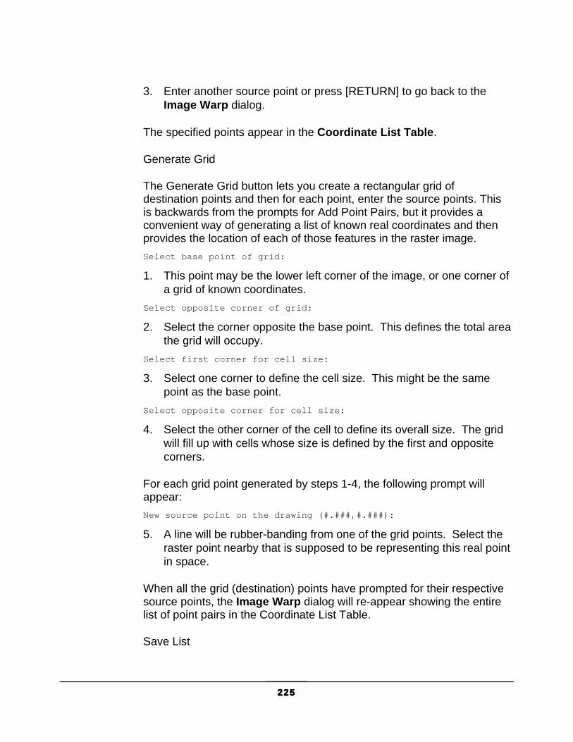
225225225225
3. Enter another source point or press [RETURN] to go back to the Image Warp dialog.
The specified points appear in the Coordinate List Table.
Generate Grid
The Generate Grid button lets you create a rectangular grid of destination points and then for each point, enter the source points. This is backwards from the prompts for Add Point Pairs, but it provides a convenient way of generating a list of known real coordinates and then provides the location of each of those features in the raster image. Select base point of grid:
1. This point may be the lower left corner of the image, or one corner of a grid of known coordinates.
Select opposite corner of grid:
2. Select the corner opposite the base point. This defines the total area the grid will occupy.
Select first corner for cell size:
3. Select one corner to define the cell size. This might be the same point as the base point.
Select opposite corner for cell size:
4. Select the other corner of the cell to define its overall size. The grid will fill up with cells whose size is defined by the first and opposite corners.
For each grid point generated by steps 1-4, the following prompt will appear: New source point on the drawing (#.###,#.###):
5. A line will be rubber-banding from one of the grid points. Select the raster point nearby that is supposed to be representing this real point in space.
When all the grid (destination) points have prompted for their respective source points, the Image Warp dialog will re-appear showing the entire list of point pairs in the Coordinate List Table.
Save List
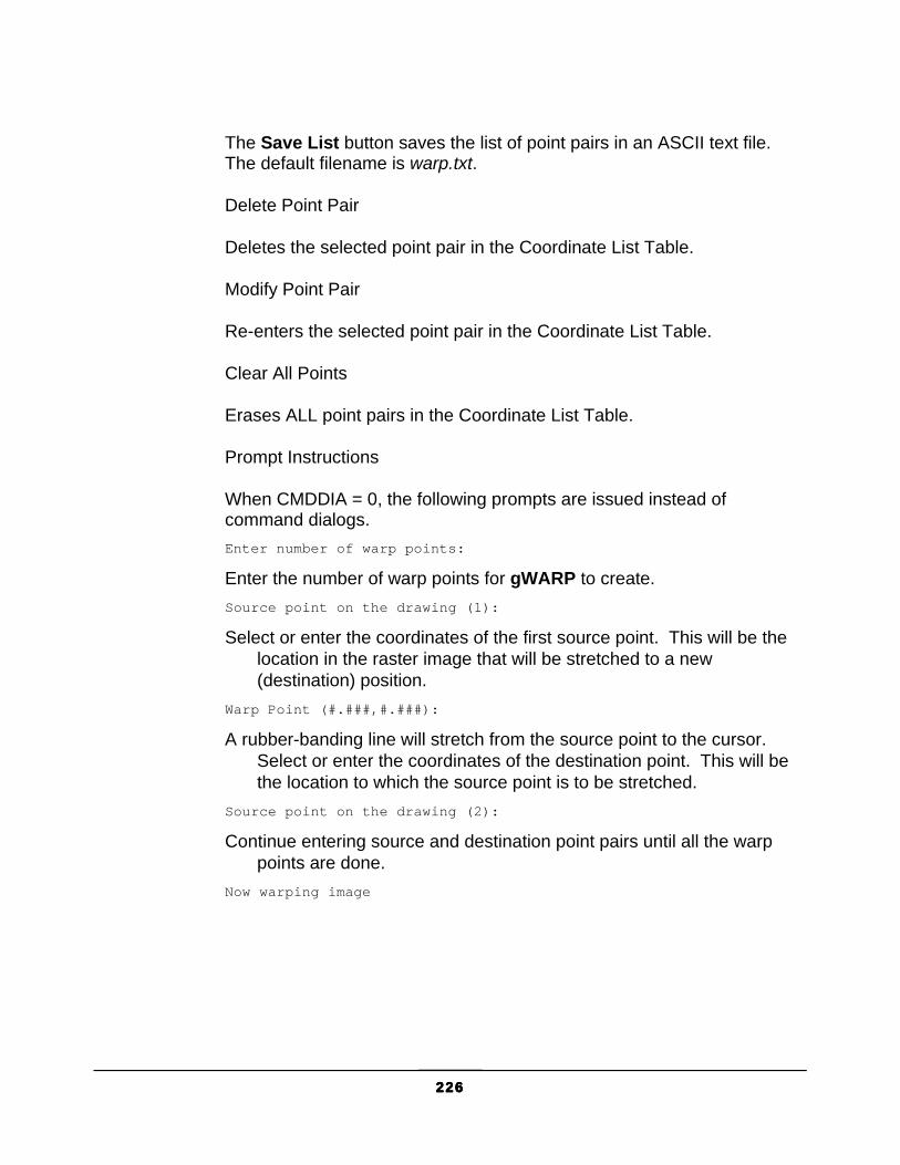
226226226226
The Save List button saves the list of point pairs in an ASCII text file. The default filename is warp.txt.
Delete Point Pair
Deletes the selected point pair in the Coordinate List Table.
Modify Point Pair
Re-enters the selected point pair in the Coordinate List Table.
Clear All Points
Erases ALL point pairs in the Coordinate List Table.
Prompt Instructions
When CMDDIA = 0, the following prompts are issued instead of command dialogs. Enter number of warp points:
Enter the number of warp points for gWARP to create. Source point on the drawing (1):
Select or enter the coordinates of the first source point. This will be the location in the raster image that will be stretched to a new (destination) position.
Warp Point (#.###,#.###):
A rubber-banding line will stretch from the source point to the cursor. Select or enter the coordinates of the destination point. This will be the location to which the source point is to be stretched.
Source point on the drawing (2):
Continue entering source and destination point pairs until all the warp points are done.
Now warping image

G L O S S A R Y O F T E R M S
227227227227
Appendix 1: Glossary of Terms Term Definition
Active Image The image currently prepared by the GTXRaster CAD series for raster editing or conversion.
ASCII American Standard Code for Information Exchange - Pronounced “Ask-ee”. The code used by most computers to represent text.
Attach AutoCAD lets you “attach” an image within a drawing. The raster data is not stored in the image - instead, an image entity “points” to the raster file on disk.
Authorize You must give GTX your HASP ID number to receive the license for full use of your software.
Auto-Convert Threshold The confidence level above which gTCONVRT will automatically convert a raster character into ACAD text without using the Character Verification Dialog.
AutoSnap™ AutoCAD’s method of dynamically snapping the crosshair to vector objects
Character Verification The QA process that lets the user verify that ICR correctly creates ACAD text entities, even if it guesses the character wrong.
Confidence Level A number between 1 and 100 representing the degree to which a character matches those it has already seen.
Contours Continuous curves that can be represented by the polyline (or pline) vector entities. Typically found on topographical maps.

G L O S S A R Y O F T E R M S
228228228228
Term Definition
Demand Loading The GTXRaster CAD series executable can “Demand Load” so it doesn't load as soon as AutoCAD starts. Instead, it waits for a GTX command to be issued, and then it loads. Read the GTX manual for instructions on Demand Loading. See your AutoCAD documentation for more information about Demand Loading.
Deskew To rotate a raster image so that it is no longer skewed.
Despeckle To remove speckles or small marks that contain no meaningful information from a drawing.
Display Color The color in which unselected raster is displayed.
DPI Dots Per Inch -The number of dots per linear inch, calibrating a raster image to real space.
HASP ID A number built into your HASP key identifying your software license. You can determine this number by running CUSTOMER.EXE.
Highlight Color The color in which selected raster is displayed.
ICR Intelligent Character Recognition - Conversion of raster text into ACAD text entities.
Integer A number evenly divisible by one (1,2,3,4,5 are integers. 1.25, 3/4, and .05 are not integers).
IOP Intelligent Object Picking™ - The proprietary method by which RCAD series selects raster shapes from a scanned drawing as if they were distinct vector entities.
MemoHASP Hardware lock that connects directly to the computer running GTXRaster CAD series.
NetHASP Hardware lock that connects to a NetHASP license manager server. NetHASP keys have more than one license per key.
Object Snapping ACAD mode of snapping the cursor to a point relative to vector geometry.
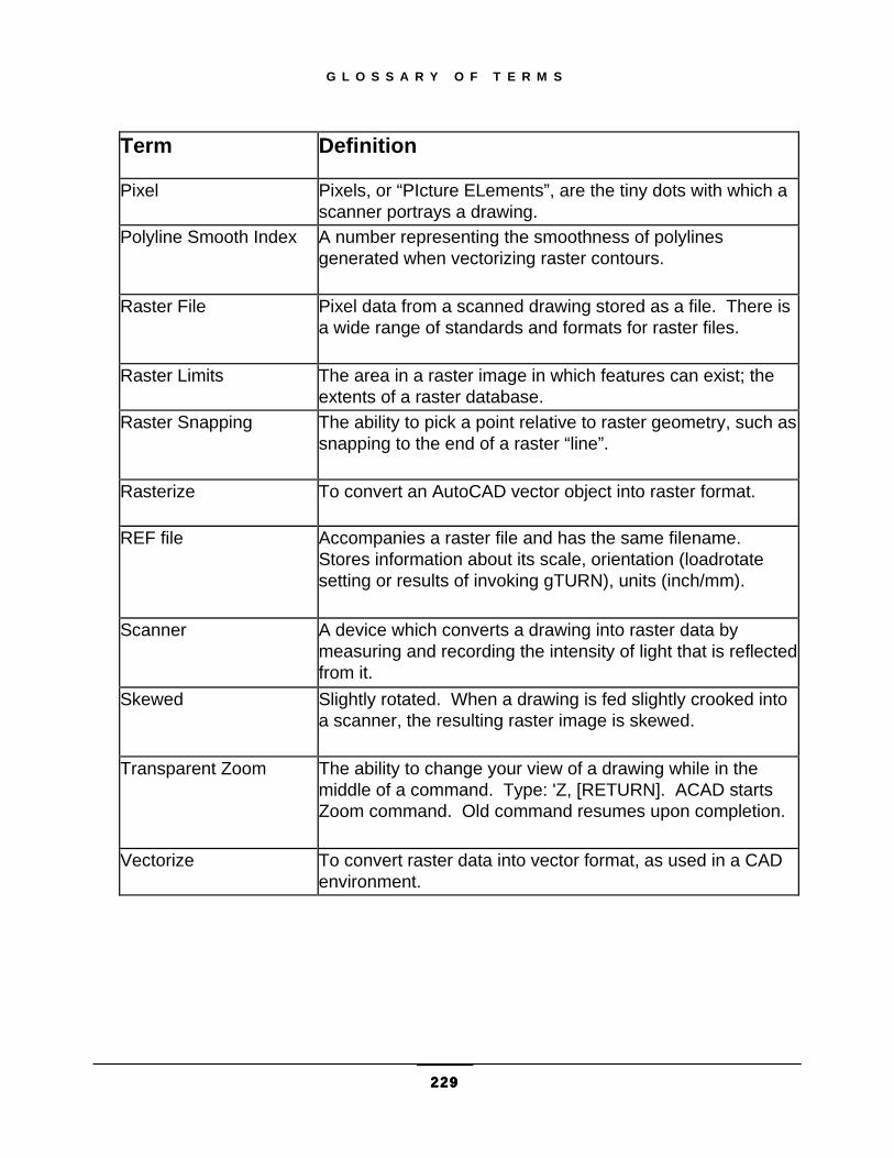
G L O S S A R Y O F T E R M S
229229229229
Term Definition
Pixel Pixels, or “PIcture ELements”, are the tiny dots with which a scanner portrays a drawing.
Polyline Smooth Index A number representing the smoothness of polylines generated when vectorizing raster contours.
Raster File Pixel data from a scanned drawing stored as a file. There is a wide range of standards and formats for raster files.
Raster Limits The area in a raster image in which features can exist; the extents of a raster database.
Raster Snapping The ability to pick a point relative to raster geometry, such as snapping to the end of a raster “line”.
Rasterize To convert an AutoCAD vector object into raster format.
REF file Accompanies a raster file and has the same filename. Stores information about its scale, orientation (loadrotate setting or results of invoking gTURN), units (inch/mm).
Scanner A device which converts a drawing into raster data by measuring and recording the intensity of light that is reflected from it.
Skewed Slightly rotated. When a drawing is fed slightly crooked into a scanner, the resulting raster image is skewed.
Transparent Zoom The ability to change your view of a drawing while in the middle of a command. Type: 'Z, [RETURN]. ACAD starts Zoom command. Old command resumes upon completion.
Vectorize To convert raster data into vector format, as used in a CAD environment.

C O N F I G U R A T I O N
230230230230
Appendix 2: Configuration The GTXRaster CAD Series receives many of its default values from a configuration file, GTXRAST.CFG. This ASCII file can be modified with a text editor such as Notepad. The list below shows the default contents of GTXRAST.CFG if you had installed it for using inches. The entries can be listed in any order.
Here is a standard configuration file:
REM * GTX Configuration *
REM ** Use “REM” or “rem” for comment lines, blank lines are ok. **REM **Defines inch or millimeter measurement standard**DrawingUnits 1Inch=1
REM **Defines the default path for saving raster files.**RasterPath =CURRENT DIRECTORY
REM **Used with gCreate and color images when gActivated.**RasterFormat =TIF
REM **Defines the available raster file formats that will be loaded withan AutoCADREM **open when a raster file with the same name is in the same directory.RasterLoadExt = TIF CG4 G4 G3 C4 GP4 B4 RNL RLC OPT BMP PCX PNG CIT *
REM **Used during gAttach and OPEN only if a GTXRaster CAD .ref file ispresent. **REM **Values for RefRotate: 0, 1, or 2REM ** 0 = Off (no rotation)REM ** 1 = Rotate (rotates Acad entity according to RefAngle)REM ** 2 = Turn (turns the actual pixels according to RefAngle)RefRotate=2
REM **Defines angle to rotate or turn a drawing during load (0, 90, 180 or270 degrees).**RefAngle=90
REM **The maximum size an image can be created or actived.REM **Number of pixels = DPI * DPI * ImageHeight * ImageWidth.REM **This limit (973440000) could create a 400DPI 78” X 78” image.REM **If set to 0 it's unlimited - warning could exceed memory capacity.MaxNumPixels=973440000
REM **Defines the marking color for selected raster in editing. Can useany color from 0-255.**
C O N F I G U R A T I O N
231231231231
HighlightColor =GREEN
REM **Defines the width of rasterized vector objects.**RasterWidth =0.01
REM **Yes option creates a backup of the original raster file.**BackupRas =NO
REM **Yes option saves the vector entity when doing Gburn or Graster.**SaveVector=NO
REM **Defines the Backup Raster Extension for the BackupRas variable. Youmust put a '.' before the extension.**BackupRasExt=.GTX
REM **Defines the Dot Per Inch resolution within the raster limits.**REM **Used for gcreate.**Resolution =200
REM **Set the number of undos that are stored. Not available at thistime**REM MAXUndo=3
REM **Sets the subformat to be used when saving TIFF files.**REM Subformat ValueREM TIFF G3 1REM TIFF G4 2REM TIFF Uncompressed 3REM TIFF Tiled V6 4TiffFormat = 2
REM **Disables a specific command. Multiple variables can be set but mustbe on separate lines.**REM disable=gattachREM disable=gload
REM * Text Configuration *REM **Sets a recognition file for GTXRaster CAD PLUS to automatically loadwhen it runs.**REM CharFile =c:\program files\gtx\raster cad V9.0\g_u_0.icr
REM **Sets a character to be listed in the ambiguous characters list boxin the gTConfig dialog.**REM Ambigchar =I
REM **Sets the initial value for the Orientation list in the gTConfigdialog.**CharOrient =0
REM **Sets the initial value of the AutoConvert Threshold setting in thegTConfig dialog.**CharThreshold =100
REM **Sets the initial value for the Min Char Size in the gTConfigdialog.**

C O N F I G U R A T I O N
232232232232
CharMinSize =0.04
REM **Sets the initial value for the Max Char Size in the gTConfigdialog.**CharMaxSize =0.4
REM **Sets the initial value for the Space Size setting in the gTConfigdialog.**CharSpaceSize =1.0
REM **Sets the initial value for Alignment Offset setting in the gTConfigdialog.**CharAlign =0
REM **Sets the initial value for Text Height setting in the gTConfigdialog.**TextHeight =0.2
REM **Sets the initial value for Max # Spaces setting in the gTConfigdialog.**MaxSpaceSize =1
REM **Sets the initial value for the word-mode verification level.WordVerifyLevel =100
REM **Sets the initial value for the word-mode force-fit level.WordForceLevel =0
REM ** 0 means touching character recognition is OFF, 1 means ONTouchingCR =0
REM ** 0 means word mode CR, 1 means character mode CRCRMode =1
REM ** Character similarity file for word recognitionREM SimFile = c:\program files\gtx\raster cad plus V9.0\gtxtext.sim
REM ** dictionary file for word recognitionREM WordFile =c:\program files\gtx\raster cad plus V9.0\base.dctREM WordFile =c:\program files\gtx\raster cad plus V9.0\User.dct
REM ** sets the default GAP JUMP sizeREM GAP_SIZE_TO_JUMP = 50
REM ** sets the layer name to be created during hatch recognitionHATCH_LAYER_NAME = HatchLayer
REM ** sets the layer name to be created during linestyle recognitionLINESTYLE_LAYER_NAME = LinestyleLayer
REM * Line Width Configuration *REM **Defines the rasterized vector width for particular colors. Can useany color from 0-255.**Pcolor 1=0.010Pcolor 2=0.020

C O N F I G U R A T I O N
233233233233
Pcolor 3=0.030Pcolor 4=0.040Pcolor 5=0.050Pcolor 6=0.060Pcolor 7=0.070Pcolor 8=0.080Pcolor 21=0.090Pcolor 23=0.100Pcolor 30=0.110Pcolor 41=0.120Pcolor 63=0.130Pcolor 153=0.140Pcolor 191=0.150Pcolor 161=0.160
REM **Set PclrUnit=0 if you want to multiply your pcolor setting by theAutoCAD scale of the Image.REM **Set PclrUnit=1 if you do NOT want to multiply your pcolor setting bythe AutoCAD scale of the Image.PclrUnit=1
REM **Product level. Settings include RCAD, RCADPLUS, RTOOLS, R2V.**ProductLevel=RCADPLUSDemomode=NO
REM **If equal to 0, it sets zero-width polylines to be rasterized just asall other entities.REM **If set to 1 all plines will be rasterized as 1 pixel wide.**Zero_Pline=0
REM **Determines the number of minutes of idle time the GTXRaster CADseries license serverREM **will allow before de-activating an inactive license and making itavailable again.**REM **Value must be at least 60. **HaspTimeOut=120
REM **Specifies the type of HASP security key being used. Possiblesettings includeREM DEFAULT, JAPAN_NEC, JAPAN_IBM.**Hasp_Type=DEFAULT
REM **Set RefDelLoad=1 if ref file needs to be deleted on doing a gATTACH,set to 0 otherwise**RefDelLoad = 0
REM **Set RefMkSave=1 if ref file needs to be created on SAVEASR13 orSAVEASR12, set to 0 otherwise**RefMkSave = 1
REM **Images are placed on this layer when attaching.REM **The current layer is used if no layer name is listed.DefaultRasterLayer=RASTER
REM ** Defines the layer color for the layer named in the

C O N F I G U R A T I O N
234234234234
REM ** DefaultRasterLayer config parameter.REM ** Can use any color from 0-255.RasterColor = RED
REM **Set BkCompMode=1 if ACAD 'Open' and raster saving in R14 shouldREM **work similar to R13 and lower versions. Images will be unlinked fromtheREM **parent dwg file and 'ref' files will be created on ACAD Save. Set to0 for true R14 functionality**BkCompMode = 0
REM ** Set to 'YES' when another 3rd party application will also be *REM ** editing raster images. This will cause more overhead to keep *REM ** keep RCAD in sync with the 3rd party application raster edits. *REM ** Default is NO. *3P_APP_EDIT=NO
REM ** When set to 'YES', RCAD will not perform transparent saving ofREM** edited raster images.REM ** Useful when another 3rd party application will also beperformingREM ** transparent saving.REM ** Default is NO.3P_APP_SAVING=NO
REM **REM ** A raster image attached with the 'gattach' command willREM **automatically be the active image (gactive) when the parameterREM ** is set to YES.REM ** Default is YES.GACTIVE_ON_GATTACH=YES
REM **Allows saving raster files over Novell 4.xENABLE_NOVELL_SAVING=YES
REM **Allows saving raster files over Novell 3.xNOVELL3_SAVE_METHOD =No
REM ** Keep the following setting at 'YES' to preventREM ** holes from forming in the warped imageWARP_CORNER_PTS=YES
Customizing The GTXRaster CAD Series uses AutoCAD profiles to determine the location of program files. You can create multiple versions of GTXRAST.CFG and have an AutoCAD profile for each one. Looking at the properties of the GTXRaster CAD Series icon you will see: "C:\Program Files\ACAD2006\acad.exe" /p GTX

C O N F I G U R A T I O N
235235235235
The standard GTX profile is called “GTX”. Use AutoCAD’s Options command to create copies of the GTX profile, modifying the paths and filenames as required. The GTXRaster CAD Series will use the first configuration file it encounters.
When AutoCAD is invoked, the GTXRAST.CFG file is checked. If the program does not recognize an entry (for example, RsterForm=) or if a value is invalid, you will get an error message. Any invalid entry is ignored and the program’s default value is used instead.
Configuration Entry Descriptions The configuration file entries are explained below and valid entries are given. Any items not included in the file or not given a value will use the default values.
Basic Configuration Parameters DrawingUnits This entry has two functions. It defines whether configuration values should be inches or millimeters and also how the World Coordinate Units should be applied to the raster image. The raster image can be either “1inch” or “1mm”; the other linear measurements in the configuration file will be in the same unit (i.e., if you specify “mm” the RasterWidth parameter will express millimeters and the value should be adjusted accordingly). The DrawingUnits value defines what inch or 1 mm on the raster image maps to in AutoCAD units. The value entered must be a real number. This defaults to AutoCAD’s initial units value.
RasterPath Defines the default path for saving raster files. You can override the directory entered here by entering the full path when prompted for a file name. The default is to save the file in the current directory.
RasterFormat Defines the default storage format of new raster files. This is used by gCREATE and when using gACTIVE on color images.
RasterLoadExt Defines the available raster formats that will be loaded with AutoCAD open when a raster file with the same name is in the same directory.

C O N F I G U R A T I O N
236236236236
RefRotate Defines the angle to rotate images with accompanying .REF files when attached with gATTACH (whether explitly invoked or incidentally invoked using AutoCAD OPEN command). Valid entries are Rotate, Turn or Off.
Rotate: Performs an AutoCAD ROTATE on the image entity, then moves the image so the new lower left corner is located where the old one was. Use this option if you want to migrate hybrid raster data back to older versions of GTX software. The disadvantage is that raster files with .REF files are attached at an angle. No raster data is changed - the image is rotated and moved!
Turn: Performs a gTURN on the image entity, which actually rotates the raster data and swaps the X and Y raster limits, resizing the image. Use this option if backward migration to earlier GTX software is not important. The advantage of this option is that images are attached at a 0° orientation.
RefAngle Defines the angle used by RefRotate parameter. Valid entries are 0, 90, 180, 270 degrees. The default is 90.
MaxNumPixels Sets the maximum number of pixels allowed in a new raster image. Default setting is 973,440,000, which at 400 dpi is equivalent to 78 x 78 inches or 1990 x 1990 millimeters.
HighlightColor Defines the default color used to highlight selected raster data. Choose a color that can be seen against the raster image and against the background color. Valid entries are the same for RasterColor. The color can be changed with the gCOLOR or gLAYER commands. The default is GREEN.
RasterWidth Sets the default raster line width to be used when vector entities are converted to raster. The entry should be an appropriate real number, or T if you want to specify the Line Width Table values. The default is .01. This value will be in inches or mm according to the DrawingUnits entry. All the values can be reset when you use the gRASTER command.
BackupRas “Yes” causes raster save to create a backup raster file. “No” deactivates the backup option.
BackupRasExt Sets the file extension for backup raster files.

C O N F I G U R A T I O N
237237237237
Resolution Defines the default resolution for new raster images.
MaxUndo Sets the number of raster undos that are stored.
Tiffformat Sets the subformat to be used when saving TIFF files:
TIFF G3 1
GIFF G4 2
TIFF UNCOMPRESSED 3
TIFF TILED V6 4
Disable Disables a specified command. Enter a single command name (i.e., gMOVE) after the word “Disable”. The software will not allow the user to invoke the specified command. To disable multiple commands, add more Disable [Command Name] lines to the configuration file.
Text Configuration Parameters CharFile sets a recognition file for GTXRaster CAD PLUS to automatically load when it is run. If you want the program to load multiple recognition files, add more CharFile [Recognition File] lines to the configuration file.
AmbigChar sets a character to be listed in the ambiguous characters list box in the gTCONFIG dialog upon starting GTXRaster CAD PLUS.
CharOrient sets the initial values for the Orientation list in the gTCONFIG dialog, determining the allowed orientations for building AutoCAD text entities. The default setting is 0. Valid entries are any angle between -360 and 360 degrees.
CharThreshold sets the initial value of the AutoConvert Threshold setting in the gTCONFIG dialog. This is the character confidence level above which the character verification dialog appears. The default value is 100, which makes the character verification dialog appear every time. Valid entries are integers from 0 to 100.

C O N F I G U R A T I O N
238238238238
CharMinSize sets the initial value for the Min Char Size setting in the gTCONFIG dialog, determining the minimum value for raster text characters when using Text IOP or gTCONVRT. The default value is .04.
CharMaxSize sets the initial value for the Max Char Size setting in the gTCONFIG dialog, determining the maximum value for the raster characters when using Text IOP or gTCONVRT. The default value is .4.
CharSpaceSize sets the initial value for the Space Size setting in the gTCONFIG dialog, defining the distance between raster characters in terms of a typical character’s width necessary for gTCONVRT to insert a space character. The default value is 1.0. Valid entries are any positive real number.
CharAlign sets the initial value for the Alignment Offset setting in the gTCONFIG dialog, determining the minimum vertical distance, relative to the text strings’ orientations, between separate lines of text in terms of a percentage of a typical character’s height. The default setting is 0. Valid entries are any real number.
TextHeight sets the initial value for the TextHeight value in the text configuration dialog.
MaxSpaceSize sets the initial value for the Max # Spaces setting in the gTCONFIG dialog, determining the maximum number of spaces that can be inserted into a text string by gTCONVRT before it breaks the text string into two separate AutoCAD text entities. The default setting is 1. Valid entries are integers 1 through 100.
MaxSpaceSize sets the initial value for the Max Space Size dialog.
WordVerifyLevel Sets the initial value for the word-mode verification level.
WordForceLevel sets the initial value for the word-mode force-fit level.
TouchingCR controls whether ICR splits touching characters. 0 means OFF, 1 means ON
CRMode controls whether ICR is performing Character recognition or Word recognition. 0 means word mode CR, 1 means character mode CR

C O N F I G U R A T I O N
239239239239
SimFile establishes the character similarity file to use for word recognition. Gtxtext.sim is hardcoded into GTX, but if another file is loaded it will override the default similarity settings.
WordFile establishes the dictionary file(s) to load on startup.
Raster-to-Vector Conversion Parameters GAP_SIZE_TO_JUMP sets the default GAP JUMP size. HATCH_LAYER_NAME sets the layer name to be created during hatch recognition. LINESTYLE_LAYER_NAME sets the layer name to be created during linestyle recognition
PColor Establishes a value in the line width configuration table.
Pcolor [Color Value]=0.050 [Line Width]
PClrUnit Determines behavior of linewidth color table when rasterizing or vectorizing with a scaled image. Set PclrUnit=0 if you want to multiply your pcolor setting by the AutoCAD scale of the Image. Set PclrUnit=1 if you do NOT want to multiply your pcolor setting by the AutoCAD scale of the image.
Other Parameters ProductLevel sets the product level for the GTXRaster CAD series to run. Settings include RCAD, RCADPLUS, RTOOLS, R2V.
DemoMode Determines whether GTXRaster CAD operates in demonstration mode. Although GTXRaster CAD will revert to demo mode if a HASP key is not present, this process can take up to a few minutes. If you install GTXRaster CAD specifically for demonstration purposes, DemoMode=YES causes it to automatically enter demonstration mode without this delay. DemoMode=NO (default setting) causes GTXRaster CAD to look for the HASP key when it first runs.
Zero_Pline Determines how polylines of zero width are rasterized. 0 causes zero-width plines to rasterized like other entities. 1 causes them to rasterize at 1 pixel wide.

C O N F I G U R A T I O N
240240240240
HaspTimeOut Determines the number of minutes idle time the GTXRaster CAD Series license server will allow before de-activating an active license and making it available again. Must be at least 120.
Hasp_Type Specifies the type of HASP security key being used. Available settings are: Default, Japan_IBM and Japan_NEC.
RefDelLoad Specifies the behavior of gATTACH as it loads a raster file with an associated .REF file. If set to 1, the .REF is deleted. If set to 0, the .REF file is kept.
RefMkSave Specifies whether a .REF file is created for each attached image when AutoCAD SAVEASR12 and SAVEASR13 commands are invoked.
DefaultRasterLayer establishes the name of a layer on which images are placed when attached using gATTACH.
RasterColor defines the layer color for the layer named in the DefaultRasterLayer config parameter. Any color from 0-255 can be used.
BkCompMode When set to 1, this overrides AutoCAD’s normal behavior to make it behave more like earlier versions of the GTXRaster CAD Series. When a drawing containing attached images is opened, any image that does not have the same name as the drawing is detatched, deleting its image entities. Any raster file with the same name as the drawing will then be attached using any .REF files to register the raster in the vector drawing.
3P_APP_EDIT should be set to Yes when another 3rd party application will also be editing raster images. This will cause more overhead to keep RCAD in sync with the 3rd party application raster edits. When set to 'YES', RCAD will not perform transparent saving of edited raster images.
3P_APP_SAVING is used when another 3rd party application will also be performing transparent saving.
GACTIVE_ON_GATTACH controls whether a raster image attached with the gATTACH command should automatically become active (gACTIVE).
ENABLE_NOVELL_SAVING allows saving raster files over Novell 4.x

C O N F I G U R A T I O N
241241241241
NOVELL3_SAVE_METHOD allows saving raster files over Novell 3.x
Line Width Configuration The line width configuration table is important to several functions of the GTXRaster CAD Series. Because AutoCAD vector entities have no line width, the GTXRaster CAD Series lets you assign raster line widths to AutoCAD vector colors.
When converting raster to vector, gCONVRT can assign different colors to vectors resulting from different raster line widths. The gRASTER command converts vector data to raster. When rasterizing, AutoCAD vector entities of different colors can be rasterized to different line widths. When smoothing raster the gSMOOTH command can snap raster data to the closest line width listed in this table.
The format for listing a color/linewidth listing is: Pcolor Color# = LineWidth
in which Color# is the AutoCAD color number to be associated with the raster linewidth. LineWidth is the width of the raster line (this can be measured using the AutoCAD Dist command).

R A S T E R F I L E F O R M A T S
242242242242
Appendix 3: Raster File Formats AutoCAD allows you to attach images in a limited number of formats:
Type Description and versions File extension BMP Windows and OS/2 bitmap format .bmp, .dib, .rle CALS-I Mil-R-Raster I .gp4, .mil, .rst, .cg4, .cal GIF CompuServe Graphics Exchange Format .gif JFIF .jpg FLIC Animator FLIC .flc, .fli PCX .pcx PICT .pct PNG .png TARGA .tga TIF/LZW .tif
AutoCAD does not let you save images - the GTXRaster CAD Series lets you do so. The available formats are shown on the next page.
The following table shows the read and write raster formats which GTXRaster CAD Series adds to AutoCAD’s native abilities. The table also covers the Rastrans utility read/write formats:
Raster Format Ext. Read Write Adobe PostScript ps - - Boeing Bedmics B4 X X GTX Uncompressed Runlength rnl X X CalComp Raster Format crf - - CCITT G3-GTX Header g3 X X CCITT G4-GTX Header g4 X X CImage Corp. dsi X EDMICS Tiled G4 c4 X X Formtek img Img X JEDMICS FileNET G4 Tiled img X X FileNET G3 Tiled img X FileNET G4 Banded img X

R A S T E R F I L E F O R M A T S
243243243243
Raster Format Ext. Read Write FileNET G3 Banded img X GraphTEC RLC rlc X HP Deskscan tif X X HP Printer Control Language pcl - - HP Raster Transfer Language rtl - - PC Paint format pcx X X Image Systems Runlength rlc X Image Systems Runlength 2 rlc X Japan Digital Labs 4000E jd4 - - Japan Digital Labs jdl - - CCITT G3-TIFF tif X X CCITT G4-TIFF tif X X Cals G4 - (MIL-STD-28002A) (28002 Type I supported. 28002 Type II not supported)
cg4 X X
Oce Graphics/NKK (Japan) oce - - Optigraphics TIFF opt - - Raster Graphics rle - - TIFF Uncompressed tif X X TIFF Version 6 Tiled tif X X TIFF Packbits tif X Versatec Block Format vbf - - Versatec VDS vds - - Fuji/Xerox MMR mmr X X Intergraph cit X X
Note: The PCX file writer provided by AutoCAD does not facilitate the
saving of the resolution of the file. Files of this type are loaded without a resolution and the gINFO command cannot report a resolution. The GTXRaster CAD Series software can save a PCX file into any of the other GTX supported file formats with a resolution of 200 dpi. When saved to another format, the file will always have a default resolution of 200 dpi.

R A S T E R F I L E F O R M A T S
244244244244
Rastrans Raster Format Translator V5.0 The Raster Format Translator (RASTRANS) is a stand-alone utility included with the GTXRaster CAD Series the same input/output formats as GTXRaster CAD. Rastrans translates raster files from one raster format to another. It can scale translated files separately in the X and Y axes. GTXRaster CAD series includes both Windows and DOS versions of GTX Rastrans. The DOS version lets you create DOS batch scripts.
Windows GUI Version The Windows version of GTX Rastrans is the executable, Rastrans.exe, located in the GTX directory.
RASTRANS MAIN SCREEN Upon running Rastrans, the main screen will appear.
The left side of the Rastrans main screen contains the Input Files List, showing all the raster files to be translated.
INPUT FILES LIST This list box displays the files to be batch-translated to the selected output file format.
ADD FILES Select to add raster files to the Input Files List.
Select any or all files to be translated into the Output File Format. Multiple files can be selected by holding [Shift] or [Control] while using the left mouse button to pick more than one file at a time.
REMOVE FILES Removes files from the Input Files List.
ABOUT RASTRANS Displays copyright information.

R A S T E R F I L E F O R M A T S
245245245245
OUTPUT FILE DIRECTORY Specifies output directory for translated files. Selecting Use Input File Directory sends output to the same directory as the source files.
OUTPUT FILE FORMAT Displays the file format to which input files are to be translated. Selecting Print to [Your Printer] sends the output directly to the current Windows system printer. Scale may need to be adjusted to fit a drawing.
DPI Use Original DPI sets resulting raster output at the same DPI as the input file. New DPI specifies an override dpi for output files.
RESOLUTION Use Original Resolution sets resulting raster output at the same Resolution as the input file. New DPI specifies an override resolution for output files.
TRANSLATE Begins translating input files into files of the output file format in the specified output directory.
QUIT Exits Rastrans.
RESTART After translating, the Translate button is renamed Restart. Clears the Input Files List, allowing you to do another batch conversion if desired.
RASTRANS.PDF For additional documentation, refer to Rastrans.pdf located in the GTX directory.
DOS Version of GTX Rastrans GTXRastrans is also available as a DOS application.

R A S T E R F I L E F O R M A T S
246246246246
USAGE: Rastrans infilename {outfilename|lpt1|lpt2|lpt3} [-rof
{calsg4|gtxg3|gtxg4|tiffg4|tiffg3|tiffu|tiled|rnl|rlc|jdl|crf|rtl|pcl|vbf|ps|opt|pcx|rle|nkk|grphtec|hpg}] [-dpiinput resolution]
Argument Description Infilename raster input filename
Input file types are autodetected independent of file extension (except b4, c4, rlc) Input file types recognized are gtxrnl, gtxg3, gtxg4, calsg4, tiffg3, tiffg4, tiff packbit, tiff uncompressed, tiled tiff, rlc, rlc2, dsig4, pcx, filenet img, b4, c4, cit
Outfilename the raster output filename -rof optional – specifies the output file format type -dpi optional – input resolution (50 to 10000) -xdpi optional - output x resolution (50 to 10000) -ydpi optional - output y resolution (50 to 10000) -odpi optional - output x and y resolution (50 to 10000) -rot optional - rotation of 90, 180, or 270

R A S T E R F I L E F O R M A T S
247247247247
Appendix 4: GTX OSR V5.0 GTX OSR (Open Systems Recognition) V5.0, a stand-alone batch conversion program, is included as part of the GTXRaster CAD PLUS and GTXRaster R2V products. GTX OSR builds a list of raster images and converts them into vector DXF, IGES or CGM files.
GTX OSR installs along with the GTXRaster CAD series and runs on the same license. No additional installation, configuration or license authorization is required.
System Requirements GTX OSR requires the following configuration:
CPU Pentium II or better Operating System Windows 98 SE, NT 4.0, 2000, XP Drive space 4 MB free hard disk space Virtual memory 100 MB swap file Memory 64 MB RAM
Using GTX OSR GTX OSR reads a list of raster files and converts the raster data to vector data. This
“raster-to-vector” conversion occurs in a batch process, yet the parameters for each drawing can be set independently.
Conversion Process Your original paper drawings need to be scanned, producing a raster file. GTX OSR performs best on a raster image without speckles. The GTXRaster CAD series can be used to clean up the raster images before running them through GTX OSR. Note: Contact your GTX sales representative for additional information
on compatible scanning and raster editing products.

R A S T E R F I L E F O R M A T S
248248248248
The conversion process begins by compiling a list of raster files by using the Open dialog. Setting the parameters before importing images establishes a global configuration. Setting the parameters after importing images configures each image independently. The conversion process begins and GTX OSR begins creating the vector conversion file of the scanned drawings.
When GTX OSR is finished converting the raster files, you will see a list of Output Files that can be imported by other viewing and/or editing software.
Main Screen Layout The left half of the Batch Command Center displays the input and output files. The right half controls the parameters of each raster file’s conversion. The Convert button begins conversion once the Import Files list is completed. An advanced pane allows detailed configuration of conversion results.
IMPORT FILES The Import Files window displays the raster files to be converted. Click on the Import Files button in the upper-left corner of the main screen to specify the raster files to convert. A file dialog will open:
Select the file or files to be converted. Use the shift and control keys to select multiple files. In the main screen you can remove any raster file from the list with the Remove button. You can also import additional files. GTX OSR may be minimized while it is converting files.
The Halt button will pause the conversion process. GTX OSR then prompts as to whether it should resume the conversion process. No cancels the operation, retaining the original selection of imported files. Jobs that have already been processed prior to selecting Halt will be saved.
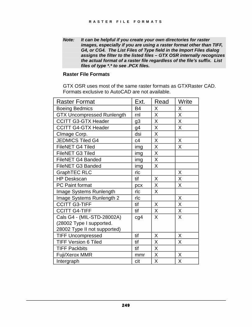
R A S T E R F I L E F O R M A T S
249249249249
Note: It can be helpful if you create your own directories for raster images, especially if you are using a raster format other than TIFF, G4, or CG4. The List Files of Type field in the Import Files dialog assigns the filter to the listed files – GTX OSR internally recognizes the actual format of a raster file regardless of the file’s suffix. List files of type *.* to see .PCX files.
Raster File Formats
GTX OSR uses most of the same raster formats as GTXRaster CAD. Formats exclusive to AutoCAD are not available.
Raster Format Ext. Read Write Boeing Bedmics B4 X X GTX Uncompressed Runlength rnl X X CCITT G3-GTX Header g3 X X CCITT G4-GTX Header g4 X X CImage Corp. dsi X JEDMICS Tiled G4 c4 X X FileNET G4 Tiled img X X FileNET G3 Tiled img X FileNET G4 Banded img X FileNET G3 Banded img X GraphTEC RLC rlc X HP Deskscan tif X X PC Paint format pcx X X Image Systems Runlength rlc X Image Systems Runlength 2 rlc X CCITT G3-TIFF tif X X CCITT G4-TIFF tif X X Cals G4 - (MIL-STD-28002A) (28002 Type I supported. 28002 Type II not supported)
cg4 X X
TIFF Uncompressed tif X X TIFF Version 6 Tiled tif X X TIFF Packbits tif X Fuji/Xerox MMR mmr X X Intergraph cit X X

R A S T E R F I L E F O R M A T S
252525250000
Output Files
The Output Files window displays conversion results. To select a file, click its name. To display the vector output, select the output file to display and click on the Show button. The Show button may need to be configured to work with a specific viewer.
CONVERT The Convert button launches the conversion process using the parameter settings on the right half of the main screen. After a conversion is complete, the label on the Convert button changes to Restart. This clears the input and output lists, allowing another conversion session to begin.
SHOW The Show button can launch an external viewer to display conversion results.
Highlight the desired filename
Select Show
The External Viewer dialog appears:
Specify the external viewer’s executable filename.
Specify any command-line arguments required by the viewer.
Select the raster file, vector file or both files.
Select Show.
EXIT The Exit button closes GTX OSR. During conversion, this is labeled, “Halt”. This button prompts to continue processing the job or to exit. Uncompleted conversions will be lost.
v5.0\demo3.dxf

R A S T E R F I L E F O R M A T S
251251251251
SCHEME Save As button opens a dialog that lets you name a scheme in which all configuration settings are saved.
Delete removes the selected scheme and is useful in maintaining a list of only the desired schemes.
Basic Pane The Basic and Advanced pane settings are controlled on the right side of the main screen. These panes determine which output format is used and how to represent text, line widths, arrowheads and contours in the final vector file.
TYPE Type can be set to CAD or Map.
CAD mode converts raster data into vector lines, arcs and circles. It is effective for mechanical drawings and line diagrams.
MAP mode converts raster data into vector polylines and is more effective for mapping applications and other drawings in which the preservation of contours is important.
UNITS Units can be set to Inches or Millimeters.
This unit applies to the Filter Size, Max Line Width and Max Char Size settings. Note Because GTX OSR uses inches internally, choosing millimeters
will use millimeters as the vector file’s units and also scale the output by 25.4.
DESTINATION The Destination directory is the location where converted files are written. This field defaults to the current directory.

R A S T E R F I L E F O R M A T S
252252252252
OUTPUT FORMAT The Output Format determine the vector file format. Choices include DXF, IGES, CGM or MTF.
DXF Autodesk Drawing eXchange Format
IGES
CGM Computer Graphics Metafile
MTF GTX Metafile
SEPARATE LAYERS Because DXF files have no linewidth for lines, arcs and circles, there needs to be some way of preserving that information. Checking Separate Layers separates DXF file output onto different layers by raster linewidth. Otherwise, all vectors are placed on the same layer.
COMPOSE SEGMENTS Compose Segments controls whether intersecting elements are continued across or broken at intersections.
On the left, intersecting lines are shown with Compose Segments enabled. On the right, the same lines with Compose Segments disabled are shown.
FILTER SIZE GTX OSR only converts raster elements above a certain size. The Filter Size specifies the maximum size for objects omitted during conversion. Any object exceeding this length in any direction will be retained; any object equal or smaller will be discarded. The entry must be a positive real number in the range of 0 to 2 inches (or 0 to 50.8 mm).
R A S T E R F I L E F O R M A T S
253253253253
Note: The Filter Size serves as the filter only if OSR is set to Vectorize Text. Otherwise, the Maximum Character Size limits the size of the smallest converted raster elements.
MAXIMUM LINE WIDTH Raster areas wider than the Maximum Line Width are recognized as filled polygons or solids. This must be a positive real number between 0 and 2 inches (or 0 to 50.8 mm).
MAXIMUM CHARACTER SIZE Any raster elements larger than the Maximum Character Size is converted as normal geometry. Any elements between the Filter Size and the Maximum Character Size are considered text, even if they are geometric dashes (dashed lines) or other small text-sized geometry. Whether they appear in the converted file depends on the Vectorize Text setting.
VECTORIZE TEXT Text-sized raster elements between the Filter Size and the Maximum Character Size are converted and placed on a text layer when this is active. Text-sized elements are omitted from the output file when this is inactive. If a piece of raster is between these sizes but is not actually text, it is still treated as text.
ARC & CIRCLE Arc & Circle is available under CAD mode only and determines whether arcs and circles are output. If inactive, arcs and circles will be interpreted and output as lines.
ARROW HEADS Arrow Heads is available under CAD mode only and determines whether arrowheads (3-sided solids) are output. If inactive, arrowheads are dropped from the output.
RECTIFY Rectify is available under CAD mode only and corrects the angle of output vector data. Lines that are close to orthogonal (0 or 90 degrees) will be snapped to 0 and 90 degrees. When disabled, lines remain at their original orientations.

R A S T E R F I L E F O R M A T S
254254254254
SMOOTHNESS Smoothness is available under MAP mode only and specifies how close together polyline vertices are drawn. The smoothest value is 1 and the least smooth value is 9.
Advanced Pane The Advanced Pane configures detailed conversion settings. These settings determine line width, maximum line gap jump and output settings.
Line Width Table
This table specifies up to eight widths for recognized lines. All entities having line width attributes are snapped to the nearest setting in the table. The entries must range from smallest to largest and be positive real numbers between 0 and 2 inches (or 0 and 50.8 mm).
CONNECT BROKEN LINES This spans gaps in broken lines, including dashed lines. When active, lines with gaps smaller than the Maximum Line Gap are merged into single lines. When inactive, lines with gaps, including dashed lines, generate individual lines.
MAXIMUM LINE GAP When Connect Broken Lines is active, lines with gaps smaller than the Maximum Line Gap are merged into single continuous lines.
OUTPUT SETTINGS The Output Format Settings dialog has three panes: DXF, CGM, and IGES.

R A S T E R F I L E F O R M A T S
255255255255
DXF SETTINGS Hollow Polygons
When active, Hollow Polygons causes AutoCAD “Solid” entities (such as arrowheads) to be displayed as hollow. When inactive, this causes solids to be solid.
Line Widths
When active, Line Widths specifies that conversion should retain line widths. Inactive Line Widths setting indicates that all lines will translate with zero width. When this is active, GTX OSR also translates lines, arcs and circles as polylines with width.
Scale
Specifies the scale factor (positive real number) used to multiple both X and Y dimensions.
CGM SETTINGS Coordinate
Integer or Real values
Precision
Specifies the word size in bits. If Coordinate is set to Integer, valid entries are 16 or 32. If Coordinate is set to Real, valid values are 32 or 64.
IGES SETTINGS System ID
Sets the system id value for IGES output.
Hollow polygons
When active, filled polygons translate into closed polygons. When inactive, they translate into closed areas with fill property.
R A S T E R F I L E F O R M A T S
256256256256
Filled circle flash
When active, filled circles translate into flash entities. When inactive, they translate into circles with fill property.
Filled circle circle
When active, filled circles translate into circles. When inactive, they translate into circles with fill property.
Default delimiters
When active, default delimiters (“,” and “;”) are output in string format “IH,” and “IH;” in the global section of IGES files. When inactive, delimiters are ignored.
Units
Units can be set to Inch or Millimeters. Specifies units of measurement for parameters.
CALS Class
CALS Class specifies what CALS compliance is required by IGES files.
Record Length
Record lengths are 80 or 82. If set to 82, CR and LF are appended to each record.
Vector Entity Translation The GTX OSR conversion process creates different entities depending on the capacity of the final output format.
Basic Shape
IGES Entity
CGM Entity DXF Entity
No Width Width Line Line Line Line Polyline Arc Arc Circular Arc Center Arc Polyarc Circle Circle Circle with hollow interior Circle Donut

R A S T E R F I L E F O R M A T S
257257257257
Basic Shape
IGES Entity
CGM Entity DXF Entity
Filled Circle
Circle with property or flash entity without fill property
Circle with solid interior polyline with width
polyline with width
Filled Polygon
Closed polyline (linear path) with or without fill property
Polygon with fill “solid” or polygon set with fill “solid”
solid polygon or polyline with no width
solid polygon or polyline with width
Text Object
Lines on TEXT layer
Polyline Lines on TEXT layer
Lines on TEXT layer
Layer Layer Begin Picture Layer Layer

R A S T E R F I L E F O R M A T S
258258258258
Command Line Version of OSR GTX OSR is accompanied by a DOS/command-line version. Running osrc.exe from the command line without arguments will display usage notes on the screen and also generate an empty OSR.ERR error file log in the same directory (if not present).
Running OSR with only an input and output file specified will cause the program to produce a configuration file. This file can then be customized using a normal text editor and specified as the desired configuration file for further OSR conversions. Different configuration files will be produced based on the type of output file specified.
Process Flow The raster-to-vector conversion consists of the following steps:
1. Read raster input file
2. Convert to GTX metafile format
3. Translate to indicated vector format
4. Write vector output file
The parameters used for the conversion from raster to GTX metafile are defined in the OSR.CFG configuration file. The parameters are contained in the OSRMAP.CFG file for GTX OSR Contours. An appropriate configuration file also defines the translation from GTX MTF format to another vector format.
The command-line entry must include the names of the input file and the output file. You can include paths if you want to override the settings for the input and output paths specified in the OSR.CFG configuration file. You may create several different configuration files with different settings and names. You can specify which OSR configuration file to use by means of the '-cfg' option.

R A S T E R F I L E F O R M A T S
259259259259
Except for RLC input files, file names can have any extensions. The program can read the file header to determine the raster format. If the output file name does not have an extension that indicates the format, the -vof (vector output format) option must be used, followed by the letters that indicate the vector format.
Configuration Files Configuration files are used with this program to customize and streamline the processing. The files can be edited with a text editor. The entry names and settings are not case sensitive. The separator between the name and '=' is not space and tab sensitive. The separator between “=“ and the setting is also not space and tab sensitive. <CR> is the delimiter of each character string. If an entry is eliminated or the setting is blank or not valid, you will get an error message and the default setting will be used.
The configuration file(s) used for a translation or conversion must be accessible for the program to operate. The program will first search the current directory, then the home directory. For conversion, the program will also check for the specific vector configuration file in the directory specified in the VectorPath of the OSR.CFG file.
If a needed configuration file cannot be found, the Program will create one with the original default settings in the current working directory and allow the user to accept or reject this substitution. The command is cancelled if the user does not want to use the program's default settings. If the needed configuration files are available but have invalid entries, the user will be prompted that OSR is using the default settings for these and the command is carried out.
THE OSR.CFG FILE The configuration files for GTX OSR contain information used by the program during the conversion process such as the units used for measurement, input and output file formats and storage locations, and conversion parameters and filter tolerances.
The following tables list the information maintained in the configuration files. The values shown are the program's default values.

R A S T E R F I L E F O R M A T S
260260260260
OSR.CFG Default OSR.CFG File Contents Variable Default Value RasterPath =./ VectorPath =./ Units =inch FilterSize =. 01 ArcCircle =yes Arrowheads =yes ComposeSegments
=yes
Layering =compress LineWidth =.08 LineWidthTable =.012, .025, .036, .050 Text =classify TextSize =.08 TextWidth =.01 TextString =Yes
THE OSRMAP.CFG FILE Default OSRMAP.CFG File Contents Variable Default Value RasterPath =./ VectorPath =./ Units =inch FilterSize =.01 Smoothing =2 ComposeSegments =yes Layering =compress LineWidthMax =.08 LineWidthTable =.012, .025, .036, .050 Text =classify TextSize =.08 TextWidth =.01 TextString =yes

R A S T E R F I L E F O R M A T S
261261261261
A brief description of the entries in the OSR.CFG and OSRMAP.CFG files follows. Entries specific to each are noted.
RasterPath: Specifies the default location for raster input files. Entry can be any valid path. The default is the current directory.
VectorPath: Specifies the default location for vector output files. Entry can be any valid path. The default is the current directory.
Units: Specifies the unit (inch or millimeter) used for the FilterSize, LineWidth, TextSize, and TextWidth parameters. Acceptable entries are INCH and MM.
FilterSize: Specifies the maximum size for objects to be deleted during raster-to-vector conversion. Any object exceeding this length in any dimension will be retained; any object equal to or smaller will be discarded. The entry must be a positive real number, in the range of 0 to 2 inches (or 0 to 50.8 mm).
ArcCircle: (GTX OSR CAD Only) Specifies whether the system will perform arc/circle recognition. NO means convert arcs and circles as lines, not arc/circle entities. Acceptable entries are YES (or Y), NO (or N).
Arrowheads: (GTX OSR CAD Only) Specifies whether filled polygons with three vertices should be recognized as arrowheads. YES indicates arrowheads will be recognized as arrowheads; NO indicates that such polygons will be recognized just as polygons. Acceptable entries are YES (or Y), NO (or N).
Smoothing: (GTX OSR Contours Only) Specifies how tightly the small deviations in the lines are followed. Valid entries are 1, 2, or 3. Option I follows the lines the most accurately. Option 3 provides a smoother, less jagged line. Option 2, the default, is a balance between the two.
ComposeSegments: Specifics how a line that intersects with another object will be processed during raster-to-vector conversion. If set to YES, the segments on either side of the intersection will be combined into one line; NO indicates that each segment will be a separate line. Acceptable entries are YES (or Y), NO (or N).

R A S T E R F I L E F O R M A T S
262262262262
Layering: Specifies whether only layers with geometry should be kept (COMPRESS) or whether the number of layers shown should be kept constant (FILL). Acceptable entries are COMPRESS and FILL.
LineWidth: Specifies the maximum width for an entity to be recognized as a line. Lines wider than the maximum will be recognized as filled polygons. The entry must be a positive real number, in the range of 0 to 2 inches (or 0 to 50.8 mm)
LineWidthTable: Specifies up to eight widths for recognized lines. All entities having line width attributes are snapped to the nearest setting in the table. The entries must go from the smallest to the largest. The entries must be positive real numbers, separated by commas, in the range of 0 to 2 inches (or 0 to 50.8 mm).
Text: Specifies whether data classified as text should be discarded (DISCARD) or vectorized (CLASSIFY). When set to CLASSIFY, the data will appear as UTEXT in GTX Metafiles; will be vectorized as lines on a TEXT layer for DXF and IGES, and vectorized as lines on the drawing image for CGM. Acceptable entries are DISCARD and CLASSIFY.
TextSize: Specifies the maximum height or width for data to be considered text. Data equal to or below this size but larger than the filter size is classified as text.
TextWidth: Specifies the text width for vectorized text. This only affects DXF, IGES, and CGM output.
TextString: Specifies whether a group of text characters will be formed as a string. This only affects MTF output. If set to YES, each group will be considered a string; NO indicates that each character will be vectorized as a single character entity. Acceptable entries are YES (or Y), NO (or N).
THE IGES.CFG FILE The IGES.CFG file is used to customize the way entities are translated so they will fit the parameters of your particular version of IGES. The following shows the default contents of the IGES.CFG file.

R A S T E R F I L E F O R M A T S
263263263263
Default IGES.CFG File Contents Variable Default Value Units =inch SystemID =cad OutlinePoly =no FilledCircle_flash =no FilledCircle_circle =no DefaultDelimiters =no RecordLength =80 CALSClass =2
The entries are explained below:
Units: Specifies the unit of measurement for parameters. Acceptable entries are INCH or MM.
SystemID: The name or identifier of the receiving program. This identifier is for operator identification only and has no bearing on the file conversion. It can be a character string of up to 10 characters.
OutlinePoly: YES specifies that filled polygons will be converted as closed polylines. NO specifies that they will be converted into closed areas with fill property. Acceptable entries are YES (or Y), NO (or N).
FilledCircle_flash: YES specifies that filled circles will be converted to flash entities. NO specifies that they will be converted to circles with fill property. Acceptable entries are YES (or Y), NO (or N).
FilledCircle_circle: YES specifies that filled circles will be converted to circles. NO specifies that they will be converted to circles with fill property. Acceptable entries are YES (or Y), NO (or N).
DefaultDelimiters: YES indicates that default delimiters (,;) should be output in string format 'IH' and 'IH;' in the global section of the IGES file. NO indicates that the delimiters should be ignored. Acceptable entries are YES (Y), NO (N).
RecordLength: Acceptable entries are 80, 82. If the setting is 82, <CR> and <LF> (line feed) are appended to each record.

R A S T E R F I L E F O R M A T S
264264264264
CALSClass: Specifies what CALS compliance is required. Acceptable entries are 0, 1, and 2. A “0” setting indicates that CALS compliance is not required.
THE DXF.CFG FILE The confirmation file for conversion to AutoCAD's DXF format has only three entries:
Default DXF.CFG File Contents Variable Default Value OutlinePoly = no Scale =1.0 Widths = no
The terms are explained below.
OutLinePoly: YES specifies that filled polygons will be converted as closed polylines. NO specifies that they will be converted into closed areas with fill property. Acceptable entries are YES (or Y), NO (or N).
Scale: Specifies the scale factor used to multiply both X and Y dimensions. It must be a positive real number.
Widths: YES specifies that the conversion should retain the line widths. NO indicates that all lines will translate with a width attribute of 0. When this is set to YES, it also translates arcs and circles as polylines with width. Acceptable entries are YES (or Y), NO (or N).
THE CGM.CFG FILE The CGM.CFG file is for conversion to CALS compatible Computer Graphics CGM format and has only two entries. The setting will generally depend on the requirements of the program in which the file will be used.
Default CGM.CFG File Contents Variable Default Value Coordinate =Real Precision =32
The terms are explained below.
R A S T E R F I L E F O R M A T S
265265265265
Coordinate: Valid entries are Real, Integer. “Real” means that coordinates are translated as decimal (floating-point) values. “Integer” means that coordinates are translated as fixed integer values.
Precision: Specifies the word size in bits. If Coordinate is set to “Real”, valid entries are 32, 64. If Coordinate is set to “Integer,” valid entries are 16, 32. The larger the number of bits, the larger the range possible.
Command-Line Entries When the program is invoked, the command line must include the input and output file names. Except for RLC input files (which must have the RLC extension), raster file names can have any extensions. The application will auto-detect the input raster file format type from its header. The output format can be indicated either by the extension to the file name or by using the “-vof” option.
The command line entries to be used are as follows:
osrc.exe: Required to invoke the program.
filename1: A name or a UNIX pipe is required to designate the input raster file.
filename2: A name or a UNIX pipe is required to designate the output vector file.
-vof <format>: optional to designate a vector output format for a file not having a standard extension. Valid formats are IGES (or IGS), DXF, CGM, MTF. Format designations can be typed in upper or lower case.
-cfg <filename>: Optional to designate a configuration file to be used instead of the standard OSR.CFG or OSRMAP.CFG file.
The input file entry and output file entry must occur in that order after the program name. Other entries can follow in any order. Separate the option used from the file name or format designation by a space. The file name must be a complete name.
Each command line can initiate only one conversion operation and can contain only one output file. However, standard UNIX pipes can be used; for instance, you may redirect the output file to a translator as in the following example:

R A S T E R F I L E F O R M A T S
266266266266
osr infile.cg4 -vof dxf | dxf2cvtrans
If any entry in the command line is incomplete or invalid, you will see an error message and the command will be cancelled. You can indicate the path to the input file. If you do not, the program will search for it in the current directory and in the directory of the RasterPath setting in the configuration file being used. The program will also search for the output location to verify that it is valid. If a file of the name you entered already exists there, you will be notified that it has been overwritten.

R A S T E R F I L E F O R M A T S
267267267267
Index Active Image
gACTIVE, 98 gINACTIVE, 150
Ambiguous Characters example, 75
Attaching images gATTACH, 70
Attaching raster gATTACH, 58
Auto Convert Threshold example, 74
Batch raster conversion gOSR, 163
Burn to raster See gBURN, gRASTER, 111
Change raster, 61, 118 Character recognition
See Converting, Raster text, 210 Clipping Boundary, 98 Color Images
Reduction to Bitonal, 98 Configuration File
Parameters, 227 Converting
example, 69 Polylines vs. Line/Arc/Circle, 125 Raster text gTCONVRT, 72, 210 gTRAIN, 217 Raster to vector gCONVRT, 71, 77 gECONVERT, 142 gVECTOR, 78, 222 Raster to Vector gCONVRT, 125 gTRACE, 66, 214
Vector to raster gRASTER, 52, 67, 171
Copying raster gARRAYgARRAYgARRAYgARRAY, 102 gCOPY, 50, 55, 130 gCUT, 135 gOFFSET, 161 gPASTE, 164
Creating new raster images gCREATE, 133
Cropping raster gCROP, 48, 134
Custom Configuration, 234 Cutting and pasting raster
gCUT, 53, 135 gPASTE, 66, 164
Deskewing raster Auto deskew, 100 gDESKEW, 46, 60, 138
Despeckling gSPECKL, 48, 202, 204
DPI, 151 Maximum Pixels, 133
Draw order, 141 Drawing raster
gLINE, 156 Editing raster
gACTIVE, 98 Erasing raster
Despeckling gSPECKL, 48, 202, 204 gCROP, 48, 134 gEDGE, 144 gERASE, 51, 145 gRUB, 66, 186
File Writers, 187

R A S T E R F I L E F O R M A T S
268268268268
gACTIVE, 98 gADESKEW, 100 gARRAYgARRAYgARRAYgARRAY, 102 gATTACH
example, 58, 70 gBURN, 111 gCHANGE, 118
example, 61 gCONVRT, 125
example, 71, 77 gCOPY, 130
example, 50, 55 gCREATE, 133 gCROP, 134
example, 48 gCUT, 135
example, 53 gDESKEW, 138
example, 46, 60 gECONVRT, 142 gEDGE, 144 gERASE, 145
example, 51 gHELP, 147 gINACTIVE, 150 gINFO, 151
example, 59 gINVERT, 153 gLINE, 156 gMIRROR, 157 gMOVE, 158
example, 56 gOFFSET, 161 gOSR, 163 gPASTE, 164
example, 53, 54, 66 gRASTER, 171
example, 52, 67 gREFLCT, 177, 179, 192 gRESIZE, 181 gROTATE, 182
example, 56
gRUB, 186 example, 66
gSAVE, 187 gSCALE, 189
example, 52 gSMOOTH, 198 gSPECKL, 202, 204
example, 48 gTCONFIG
example, 72 gTCONVRT
example, 72 gTRACE, 214
example, 66 gTRAIN, 217 gTURN, 221
example, 58 GTXRAST.CFG, 227 gVECTOR, 222
example, 78 gWARP, 224 Help
gHELP, 147 ICR files, 74 ICR Plus, 217 Intelligent Object Picking. See IOP, 93 Inverting raster images
gINVERT, 153 IOP
Add, 94 ALL, 94 ARc, 94 CIrcle, 94 CRossing, 94 Fence, 94 Inside, 94 Line, 94 Object, 94 PCrossing, 94 PInside, 94 PRevious, 94 PWindow, 94

R A S T E R F I L E F O R M A T S
269269269269
Remove, 94 Segment, 94 TEXTLine, 94 TEXTWindow, 94 unDer, 94 Undo, 94 View, 94 Window, 94
Linetypes Dashed example, 77
Loading raster gATTACH, 58, 70 gPASTE, 66, 164
Mirroring raster gMIRROR, 157 gREFLECT, 177, 179, 192
Moving raster gMOVE, 56, 158
Negative images gINVERT, 153
NetWare, 22, 240 Novell, 22, 240 Offsetting raster
gOFFSET, 161 OPEN, 68 OSR, 163 Pasting raster
gPASTE, 53, 54, 66, 164 perpendicular, 95 QUIT, 68 Raster files
Formats, 242, 247 Information gINFO, 59, 151
Raster Files Limits, 151
Raster Formats Saving, 187
Raster limits gRESIZE, 181
Raster selection
See IOP, 62 Raster snap
tangent, 95 Raster snaps, 95
center, 95 edge, 95 end, 95 example, 65 intersection, 95 List, 95 mid-arc, 95 midpoint, 95 near, 95 none, 95 perpendicular to arc, 95 Running, 95
raster-to-vector parameters, 71
Recognition files, 74 Recognition Files
Training, 217 Reflecting raster
gMIRROR, 157 gREFLECT, 177, 179, 192
Resizing images gRESIZE, 181
Resolution, 151 Maximum Pixels, 133
Rotating raster, 46 gDESKEW, 60, 138 gROTATE, 56, 182 gTURN, 58, 221 on load, 236
Rubber sheeting gWARP, 224
Saving raster AutoCAD SAVE command SAVE, 50 gCUT, 135 gSAVE, 187 QUIT, 68
Scaling raster
R A S T E R F I L E F O R M A T S
270270270270
gSCALE, 52, 189 Smoothing raster
gSMOOTH, 198 Snapping
See raster snaps, 95 Speckle removal
gSPECKL, 48, 202, 204 Stretching raster geometry
gCHANGE, 118
Title blocks, 134 Tracing raster with vector
gTRACE, 214 Turning an image
See Rotating raster, 58 Vectorizing raster
See Converting, Raster to vector, 71 Warping raster
gWARP, 224