gtxtm 327 transponder installation manualexpaircraft.com/pdf/gtx327-im.pdf · gtx 327 installation...
TRANSCRIPT

á
Garmin International, Inc.
190-00187-02 Revision JMay 2003
GTXTM 327TRANSPONDERINSTALLATIONMANUAL

Page A GTX 327 Installation ManualRev J 190-00187-02
© Copyright 1999-2003Garmin Ltd. or its subsidiaries
All Rights Reserved
Except as expressly provided herein, no part of this manual may be reproduced, copied, transmitted, disseminated,downloaded or stored in any storage medium, for any purpose without the express prior written consent of Garmin.Garmin hereby grants permission to download a single copy of this manual and of any revision to this manual onto ahard drive or other electronic storage medium to be viewed and to print one copy of this manual or of any revisionhereto, provided that such electronic or printed copy of this manual or revision must contain the complete text ofthis copyright notice and provided further that any unauthorized commercial distribution of this manual or anyrevision hereto is strictly prohibited.
Garmin International, Inc.1200 E. 151st Street
Olathe, KS 66062 USATelephone: 913-397-8200
Aviation Panel-Mount Technical Support Line (Toll Free): 1-888-606-5482www.garmin.com
Garmin (Europe) Ltd.Unit 5, The Quadrangle, Abbey Park Industrial Estate
Romsey, SO51 9DL, U.K.Telephone: 44/1794.519944
RECORD OF REVISIONS
Revision RevisionDate
Description ECO #
A 01/19/00 Initial Release 12550B 02/28/00 Update Configuration Procedure 12785C 06/01/00 Update Configuration Procedure. Add JTSO
references and STC form.13450
D 07/18/00 Correct Interconnect Diagram, New RF ConnectorSpacer P/N, Plus Misc Changes.
13763
E 8/01/01 Add P/N’s @ Section 1.5 16263F 11/06/01 Updates and Clarifications 16867G 05/01/02 Updated unit and accessory part numbers 18295H 11/01/02 Revised to reflect new software 19608J 5/22/03 Revised to reflect software 2.06 21163
LIST OF EFFECTIVE PAGES
Page Rev.A .................Ji ...................Jii ..................Jiii.................Jiv .................Jv ..................Jvi .................J
Page Rev.1 ..................J2 ..................J3 ..................J4 ..................J5 ..................J6 ..................J7 ..................J8 ..................J
Page ...... Rev.9..................J10 ................J11 ................J12 ................J13 ................J14 ................J15 ................J16 ................J
Page Rev.17................J18................J19................J20................J21................J22................J23................J24................J
Page Rev.25................ J26................ J27................ J28................ J29................ J30................ J31................ J32................ J
Page Rev.33................ J34................ J35................ J36................ J37................ J38................ J39................ J40................ J
Page Rev.41................ J42........ Blank43................ J44........ Blank45................ J46........ Blank47................ J48........ Blank
Page Rev.49................ J50........ Blank51................ J52................ J

GTX 327 Installation Manual Page i190-00187-02 Rev J
INFORMATION SUBJECT TO EXPORT CONTROL LAWS
This document may contain information which is subject to the Export Administration Regulations ("EAR") issued by theUnited States Department of Commerce (15 CFR, Chapter VII, Subchapter C) and which may not be exported, released,or disclosed to foreign nationals inside or outside of the United States without first obtaining an export license. Aviolation of the EAR may be subject to a penalty of up to 10 years imprisonment and a fine of up to US $1,000,000 underSection 2410 of the Export Administration Act of 1979. Include this notice with any reproduced portion of this document.
WARNING
This product, its packaging, and its components contain chemicals known to the State of California to cause cancer, birthdefects, or reproductive harm. This Notice is being provided in accordance with California's Proposition 65. If you haveany questions or would like additional information, please refer to our web site at www.garmin.com/prop65.

Page ii GTX 327 Installation ManualRev J 190-00187-02
This page intentionally left blank
GTX 327 Installation Manual Page iii190-00187-02 Rev J
TABLE OF CONTENTS
PARAGRAPH PAGE
1. GENERAL DESCRIPTION .................................................................................................................11.1 INTRODUCTION.................................................................................................................................11.2 EQUIPMENT DESCRIPTION.............................................................................................................11.3 MUTUAL SUPPRESSION PULSES ...................................................................................................11.4 INTERFACE SUMMARY ...................................................................................................................11.5 GTX 327 TRANSPONDER SPECIFICATIONS .................................................................................2
1.5.1 Transponder Specifications........................................................................................................21.5.2 Physical Characteristics of the GTX 327...................................................................................3
1.6 EQUIPMENT AVAILABLE ................................................................................................................31.6.1 Configurations Available ...........................................................................................................31.6.2 Installation Accessories .............................................................................................................3
1.7 ADDITIONAL EQUIPMENT REQUIRED.........................................................................................41.8 INSTALLATION APPROVAL............................................................................................................41.9 ATC TRANSPONDER TESTS AND INSPECTIONS ........................................................................41.10 LIMITED WARRANTY ......................................................................................................................5
2. INSTALLATION..................................................................................................................................72.1 INTRODUCTION.................................................................................................................................72.2 UNPACKING AND INSPECTING EQUIPMENT..............................................................................72.3 ANTENNA INSTALLATION..............................................................................................................7
2.3.1 Location Considerations ............................................................................................................72.3.2 Antenna Installation ...................................................................................................................72.3.3 Installation Approval Considerations for Pressurized Aircraft ..................................................82.3.4 Antenna Cable Installation.........................................................................................................92.3.5 Antenna Cable Connectors ........................................................................................................9
2.4 GTX 327 INSTALLATION................................................................................................................112.5 COOLING AIR ...................................................................................................................................112.6 ELECTRICAL CONNECTIONS .......................................................................................................12
2.6.1 Power and Lighting Function ..................................................................................................142.6.2 Altitude Functions....................................................................................................................142.6.3 RS-232 Serial Data Electrical Characteristics..........................................................................17
3. POST INSTALLATION CONFIGURATION & CHECKOUT PROCEDURE ................................193.1 AIRCRAFT STATION LICENSING REQUIREMENTS .................................................................193.2 OPERATION ......................................................................................................................................19
3.2.1 Function Selection Switches ....................................................................................................203.2.2 Function Display......................................................................................................................223.2.3 Code Selection .........................................................................................................................23
Page iv GTX 327 Installation ManualRev J 190-00187-02
PARAGRAPH PAGE
3.3 CONFIGURATION PAGES ..............................................................................................................233.3.1 DISPLAY MODE Page ...........................................................................................................243.3.2 DISPLAY BACKLIGHT Page................................................................................................243.3.3 KEY LIGHTING Page ............................................................................................................253.3.4 CONTRAST CONFIGURATION Page ..................................................................................273.3.5 RS-232 INPUT/OUTPUT Page...............................................................................................283.3.6 OPERATION CONFIGURATION Pages...............................................................................293.3.7 AIRCRAFT TYPE Page ..........................................................................................................313.3.8 RS-232 INPUT VIEW Page ....................................................................................................313.3.9 GRAY CODE INPUT Page.....................................................................................................313.3.10 EXTERNAL SWITCH Page ...................................................................................................323.3.11 ANALOG INPUT Page ...........................................................................................................32
APPENDIX A. CERTIFICATION DOCUMENTS....................................................................................33A.1 CONTINUED AIRWORTHINESS ....................................................................................................33A.2 ENVIRONMENTAL QUALIFICATION FORM ..............................................................................36
APPENDIX B. ASSEMBLY AND INSTALLATION DRAWINGS ........................................................39
APPENDIX C. STC PERMISSION............................................................................................................51

GTX 327 Installation Manual Page v190-00187-02 Rev J
LIST OF ILLUSTRATIONS
FIGURE PAGE
2-1 RF Connector Assembly .....................................................................................................................102-2 Dual GTX 327, Single Encoder, Serial Input Connections.................................................................153-1 GTX 327 Front Panel ..........................................................................................................................19B1 GTX 327 Outline Drawing..................................................................................................................41B2 GTX 327 Connector/Rack Kit Assembly Drawing.............................................................................43B3 GTX 327 Recommended Panel Cutout Dimensions ...........................................................................45B4 GTX 327 Interconnect Wiring Diagram..............................................................................................47B5 Dual Transponder Interconnect Wiring Diagram, Encoding Altitude Connections ...........................49
LIST OF TABLES
TABLE PAGE
2-1 Recommended Antenna Cable Type .....................................................................................................92-2 Pin Contact Part Numbers ...................................................................................................................122-3 Recommended Crimp Tools................................................................................................................122-4 P3271 Pin Assignments.......................................................................................................................132-5 Aircraft Power Pin Assignments .........................................................................................................142-6 Aircraft Lighting Pin Assignments......................................................................................................142-7 Encoded Altitude Pin Assignments .....................................................................................................152-8 Discrete Inputs Pin Assignments.........................................................................................................162-9 RS 232 Input/Output Pin Assignments ...............................................................................................16

Page vi GTX 327 Installation ManualRev J 190-00187-02
GTX 327 HARDWARE MOD LEVEL HISTORY
The following table identifies hardware modification (Mod) Levels for the GTX 327 Transponder. ModLevels are listed with the associated service bulletin number, service bulletin date, and the purpose of themodification. The table is current at the time of publication of this manual (see date on front cover) and issubject to change without notice. Authorized GARMIN Sales and Service Centers are encouraged to accessthe most up-to-date bulletin and advisory information on the GARMIN Dealer Resource web site atwww.garmin.com using their GARMIN-provided user name and password.
MODLEVEL
SERVICEBULLETINNUMBER
SERVICEBULLETIN
DATE
PURPOSE OF MODIFICATION
At the time of this revision, the current software version for the GTX 327 is 2.06. Thesoftware version and information in this document are subject to change without notice. Visitthe Garmin web site (www.garmin.com) for current manual updates and supplementalinformation concerning the operation of this and other Garmin products.
NOTE

GTX 327 Installation Manual Page 1190-00187-02 Rev J
1. GENERAL DESCRIPTION
1.1 INTRODUCTION
This manual describes the physical, mechanical and electrical characteristics, plus the installationrequirements and operating instructions for the Garmin GTX 327 Digital Display Transponder system.Information pertaining to the maintenance, alignment and procurement of replacement parts is found inthe GTX 327 Maintenance Manual, Garmin P/N 190-00187-05. After installation of the GTX 327, FAAForm 337 must be completed by an appropriately certificated agency and ATC transponder tests requiredby 14 CFR, Part 91.413 must be completed to return the aircraft to service.
1.2 EQUIPMENT DESCRIPTION
The Garmin GTX 327 is a panel-mounted transponder with the addition of altitude reporting and timingfunctions. The transponder is a radio transmitter and receiver that operates on radar frequencies,receiving ground radar or TCAS interrogations at 1030 MHz and transmitting a coded response of pulsesto ground-based radar on a frequency of 1090 MHz.
As with other Mode A/Mode C transponders, the GTX 327 replies with any one of 4,096 codes, whichdiffer in the position and number of pulses transmitted. By replying to ground transmissions or TCASinterrogations, the GTX 327 enables ATC to display aircraft identification, altitude and groundspeed onATC radar screens or TCAS traffic indicators. The GTX 327 is equipped with IDENT capability thatactivates the Special Position Identification (SPI) pulse for 18 seconds.
The GTX 327 is configured with all key controls. The layout of the front panel keys and displayssegregates the transponder’s primary functions from the secondary timing functions. The unit can beconfigured so the aircraft avionics master bus can turn the unit on.
1.3 MUTUAL SUPPRESSION PULSES
Other equipment on board the aircraft may transmit in the same frequency band as the transponder, suchas DME or another transponder. Mutual suppression is a synchronous pulse that is sent to the otherequipment to suppress transmission of a competing transmitter for the duration of the pulse traintransmission. The transponder transmission may be suppressed by an external source and otherequipment on board may be suppressed by the transponder. This feature is designed to limit mutualinterference.
1.4 INTERFACE SUMMARY
The GTX 327 provides the following interface connections via the rear connector:
• Ten (10) encoding altimeter inputs.
• External IDENT input.
• External STBY input.
• External suppression pulse input.
• Switched power output of up to 1.5 amps (for digital altitude encoder power).

Page 2 GTX 327 Installation ManualRev J 190-00187-02
• Aircraft power input (11 to 33 volts).
• Aircraft dimming bus input voltage.
• Aircraft master switch turn-on option.
• Serial altitude, airdata or GPS input.
• Serial altitude output.
1.5 GTX 327 TRANSPONDER SPECIFICATIONS
1.5.1 Transponder Specifications
SPECIFICATION CHARACTERISTIC
TSO, JTSO TSO C74c Class 1A, JTSO-C74c Class 1A
TSO ENV CAT Refer to appendix A
FCC Authorization Emission Designator 11M0M1D
Applicable Documents FAA TSO C74c, JTSO-C74c, RTCA DO-160D
Software RTCA DO-178B Level D
Temperature Range -20°C to +55°C (Continuous Operation)
Power Requirements 11.0 to 33.0 Vdc; Power Input: 15 Watts typical, 22 Wattsmaximum
Humidity 95% @ +55°C for 16 Hours; 85% @ +38°C for 32 Hours
Altitude 50,000 Feet
Transmitter Frequency 1090 MHz
Transmitter Power 125 Watts minimum, 150 Watts nominal at the antennathrough 1.5 dB coax.
Receiver Frequency 1030 MHz
Receiver Sensitivity -74 dBm Nominal for 90% replies
Mode A Capability 4096 Identification Codes
Mode C Capability 100 Foot Increments from -1000 to 63,000 feet
External Suppression Input Low ≤ 0.5 V; High ≥ 8 V

GTX 327 Installation Manual Page 3190-00187-02 Rev J
1.5.2 Physical Characteristics of the GTX 327
SPECIFICATION CHARACTERISTIC
Bezel Height 1.65 inches (41 mm)
Bezel Width 6.25 inches (159 mm)
Rack Height (Dimple to Dimple) 1.71 inches (43 mm)
Rack Width 6.30 inches (160 mm)
Depth Behind Panel withConnectors (measured fromface of aircraft panel to rear ofconnector backshells)
8.78 inches (223 mm)
GTX 327 Unit Weight 2.4 lbs. (1.1 kg)
GTX 327 Weight (Installed withrack and connectors)
3.0 lbs. (1.4 kg)
1.6 EQUIPMENT AVAILABLE
1.6.1 Configurations Available
GARMIN P/N FRONT PANEL WITH INSTALL KIT010-00188-00 Black No010-00188-03 Black Yes010-00188-10 Gray No010-00188-11 Gray Yes
1.6.2 Installation Accessories
ITEM GARMIN P/NMounting Rack 115-00285-00Connector Kit 011-00651-01Rear Backplate 011-00677-01Mounting Rack, Backplate and Connector Kit(Includes 115-00285-00, 011-00677-01 and 011-00651-01)
010-10161-01
Garmin GTX 327 Antenna kit* 010-10160-00
* Note: A transponder antenna approved to TSO C66( ) or C74( ) that has been installed to meet therequirements of this manual may be approved for use with the GTX 327.

Page 4 GTX 327 Installation ManualRev J 190-00187-02
1.7 ADDITIONAL EQUIPMENT REQUIRED
• Antenna Sealant - Use antenna manufacturer’s instructions, install according to FAAAC 43.13-1B and AC 43.13-2A.
• Cables - The installer will supply all system cables. Cable requirements and fabrication isdetailed in Section 2 of this manual.
• Hardware - #6-32 x 100° Flat Head Screw (6 ea.) and #6-32 Self-Locking Nut (6 ea.). Hardwarerequired to mount installation rack is not provided.
• Encoding Altitude Digitizer - Use encoding altimeter manufacturer’s instructions, installaccording to FAA AC 43.13-1B and AC 43.13-2A. The Garmin GAE 43 (Garmin P/N013-00066-00) can provide altitude data in either serial or parallel gray code format.
1.8 INSTALLATION APPROVAL
The conditions and tests required for TSO approval of the GTX 327 Transponder and antenna areminimum performance standards. It is the responsibility of those desiring to install this transponder andantenna either on or within a specific type or class of aircraft to determine that the aircraft installationstandards are within the TSO standards. For GTX 327 TSO compliance, see Appendix A. For antennaTSO compliance, refer to antenna manufacturer’s literature.
1.9 ATC TRANSPONDER TESTS AND INSPECTIONS
The ATC transponder tests required by 14 CFR, Part 91.413 may be conducted using a bench check orportable test equipment and must meet the requirements prescribed in Part 43 Appendix F.
If portable test equipment with appropriate coupling to the aircraft antenna system is used, operate the testequipment for ATCRBS transponders at a nominal rate of 235 interrogations per second to avoid possibleATCRBS interference. An additional 3 dB loss is allowed to compensate for antenna coupling errorsduring receiver sensitivity measurements conducted in accordance with Part 43 Appendix F, Paragraph(c)(1) when using portable test equipment.

GTX 327 Installation Manual Page 5190-00187-02 Rev J
1.10 LIMITED WARRANTY
This Garmin product is warranted to be free from defects in materials or workmanship for oneyear from the date of purchase. Within this period, Garmin will at its sole option, repair orreplace any components that fail in normal use. Such repairs or replacement will be made at nocharge to the customer for parts or labor, provided that the customer shall be responsible for anytransportation cost. This warranty does not cover failures due to abuse, misuse, accident orunauthorized alteration or repairs.
THE WARRANTIES AND REMEDIES CONTAINED HEREIN ARE EXCLUSIVE AND INLIEU OF ALL OTHER WARRANTIES EXPRESS OR IMPLIED OR STATUTORY,INCLUDING ANY LIABILITY ARISING UNDER ANY WARRANTY OFMERCHANTABILITY OR FITNESS FOR A PARTICULAR PURPOSE, STATUTORY OROTHERWISE. THIS WARRANTY GIVES YOU SPECIFIC LEGAL RIGHTS, WHICH MAYVARY FROM STATE TO STATE.
IN NO EVENT SHALL GARMIN BE LIABLE FOR ANY INCIDENTAL, SPECIAL,INDIRECT OR CONSEQUENTIAL DAMAGES, WHETHER RESULTING FROM THE USE,MISUSE, OR INABILITY TO USE THIS PRODUCT OR FROM DEFECTS IN THEPRODUCT. Some states do not allow the exclusion of incidental or consequential damages, sothe above limitations may not apply to you.
Garmin retains the exclusive right to repair or replace the unit or software or offer a full refundof the purchase price at its sole discretion. SUCH REMEDY SHALL BE YOUR SOLE ANDEXCLUSIVE REMEDY FOR ANY BREACH OF WARRANTY.
To obtain warranty service, contact your local Garmin Authorized Service Center. Forassistance in locating a Service Center near you, call Garmin Customer Service at one of thenumbers shown below.
Products sold through online auctions are not eligible for rebates or other special offers fromGarmin. Online auction confirmations are not accepted for warranty verification. To obtainwarranty service, an original or copy of the sales receipt from the original retailer is required.Garmin will not replace missing components from any package purchased through an onlineauction.
Garmin International, Inc. Garmin (Europe) Ltd.1200 East 151st Street Unit 5, The Quadrangle, Abbey Park Industrial EstateOlathe, Kansas 66062, U.S.A. Romsey, SO51 9DL, U.K.Phone: 913/397.8200 Phone: 44/1794.519944FAX: 913/397.0836 FAX: 44/1794.519222

Page 6 GTX 327 Installation ManualRev J 190-00187-02
This page intentionally left blank

GTX 327 Installation Manual Page 7190-00187-02 Rev J
2. INSTALLATION
2.1 INTRODUCTION
This section provides the necessary information for installing the GTX 327 Transponder, and whererequired, optional accessories. Installation of the GTX 327 will differ according to equipment locationand other factors. Cabling will be fabricated by the installing agency to fit these various requirements.This section contains interconnect diagrams, mounting dimensions, and information pertaining toinstallation. Any deviations from the installation instructions prescribed in this document shall beaccomplished in accordance with the requirements set forth in FAA AC 43.13-1B and AC 43.13-2A.
2.2 UNPACKING AND INSPECTING EQUIPMENT
Carefully unpack the equipment and make a visual inspection of the unit for evidence of damage incurredduring shipment. If the unit is damaged, notify the carrier and file a claim. To justify a claim, save theoriginal shipping container and all packing materials. Do not return the unit to Garmin until the carrierhas authorized the claim.
Retain the original shipping containers for storage. If the original containers are not available, a separatecardboard container should be prepared that is large enough to accommodate sufficient packing materialto prevent movement.
2.3 ANTENNA INSTALLATION
2.3.1 Location Considerations
A. The antenna (Garmin P/N 010-10160-00) should be well removed from any majorprotrusions, such as engine(s), propeller(s), and antenna masts. It should also be as far aspractical from landing gear doors, access doors, or other openings that could effect itsradiation pattern.
B. The antenna should be mounted on the underside of the aircraft and in a vertical positionwhen the aircraft is in level flight.
C. Avoid mounting the antenna within three feet of the ADF sense antenna or any othercommunication antenna and six feet from the DME antenna.
D. To prevent RF interference, the antenna must be physically mounted a minimum distanceof three feet from the GTX 327.
NOTEIf the antenna is being installed on a composite aircraft, ground planes must sometimes beadded. Conductive wire mesh, radials, or thin aluminum sheets embedded in the compositematerial provide the proper ground plane allowing the antenna pattern (gain) to bemaximized for optimum transponder performance.
2.3.2 Antenna Installation
A. Install the antenna according to the antenna manufacturer’s instructions andFAA AC 43.13-1B and AC 43.13-2A.

Page 8 GTX 327 Installation ManualRev J 190-00187-02
2.3.3 Installation Approval Considerations for Pressurized Aircraft
Antenna and cable installations on pressurized cabin aircraft require FAA approved installation designand engineering substantiation data whenever such installations incorporate alteration (penetration) of thecabin pressure vessel by connector holes and/or mounting arrangements.
For needed engineering support pertaining to the design and approval of such pressurized aircraft antennainstallations, it is recommended that the installer proceed according to any of the following listedalternatives:
1. Obtain approved antenna installation design data from the aircraft manufacturer.
2. Obtain an FAA approved Supplemental Type Certificate (STC) pertaining to and valid for thesubject antenna installation.
3. Contact the FAA Aircraft Certification Office in the appropriate Region and request identificationof FAA Designated Engineering Representatives (DERs) who are authorized to prepare andapprove the required antenna installation engineering data.
4. Obtain FAA Advisory Circular AC-183C and select (and contact) a DER from the roster ofindividuals identified thereunder.
5. Contact an aviation industry organization such as the Aircraft Electronics Association and requesttheir assistance.

GTX 327 Installation Manual Page 9190-00187-02 Rev J
2.3.4 Antenna Cable Installation
When routing antenna cables, observe the following precautions:
• All cable routing should be kept as short as possible and as direct as possible.
• Avoid sharp bends.
• Avoid routing cables near power sources (e.g., 400 Hz generators, trim motors, etc.) ornear power for fluorescent lighting.
• Avoid routing cable near ADF antenna cable (allow at least a 12-inch separation).
The following table lists examples of the recommended antenna cable vendors and the type of cable to beused for specific lengths of cable. Any cable meeting specifications is acceptable for the installation. Themaximum coaxial cable attenuation at 1090 MHz must not exceed 1.5 dB.
Table 2-1. Recommended Antenna Cable Type
Max. Length (feet) ECS Type MIL-C-17 Type RG Type
8.8 M17/128 RG40010.0 3C142B12.5 M17/112 RG30417.0 311601 M17/127 RG39321.0 31150127.0 31120141.0 310801
Supplier Information Vendor: ElectronicCable Specialists5300 W. Franklin DriveFranklin, WI 53132Tel: 800-327-9473414-421-5300Fax: 414-421-5301www.ecsdirect.com
MIL-C-17 types: Seecurrent issue ofQualified Products ListQPL-17.
RG types: See currentissue of QualifiedProducts List QPL-17.
2.3.5 Antenna Cable Connectors
One of two rack connectors are provided (item 6 or 12 in the installation drawing, figure B2 on page 39).RF Adapter item 12 (Garmin P/N 330-00326-00) requires the cable to be terminated to an appropriatetype BNC plug (provided by installer), which is then attached to item 12. Any 50 ohm, double shieldedcable may be used, provided it introduces less than 1.5 dB attenuation at 1 GHz including the connector.
Connector item 6 (Garmin P/N 330-00198-00) requires the cable to be terminated directly to it and canaccommodate only M17/128 (RG-400) cable. The completed cable including connectors must introduceno more than 1.5 dB attenuation at 1 GHz. Instructions for installing the item 6 are shown below (stepsA-G).
Page 10 GTX 327 Installation ManualRev J 190-00187-02
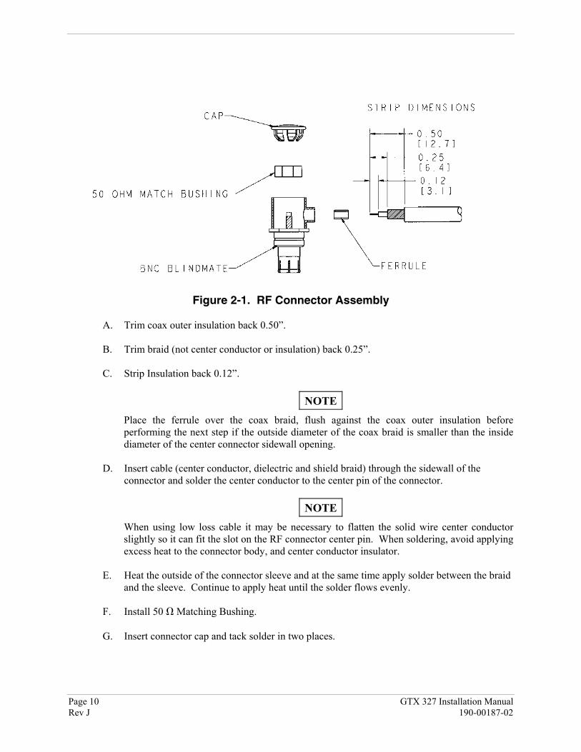
Figure 2-1. RF Connector Assembly
A. Trim coax outer insulation back 0.50”.
B. Trim braid (not center conductor or insulation) back 0.25”.
C. Strip Insulation back 0.12”.
NOTEPlace the ferrule over the coax braid, flush against the coax outer insulation beforeperforming the next step if the outside diameter of the coax braid is smaller than the insidediameter of the center connector sidewall opening.
D. Insert cable (center conductor, dielectric and shield braid) through the sidewall of theconnector and solder the center conductor to the center pin of the connector.
NOTEWhen using low loss cable it may be necessary to flatten the solid wire center conductorslightly so it can fit the slot on the RF connector center pin. When soldering, avoid applyingexcess heat to the connector body, and center conductor insulator.
E. Heat the outside of the connector sleeve and at the same time apply solder between the braidand the sleeve. Continue to apply heat until the solder flows evenly.
F. Install 50 Matching Bushing.
G. Insert connector cap and tack solder in two places.

GTX 327 Installation Manual Page 11190-00187-02 Rev J
2.4 GTX 327 INSTALLATION
NOTES
Avoid installing the unit near heat sources. If this is not possible, ensure that additionalcooling is provided. Allow adequate space for installation of cables and connectors. Theinstaller will supply and fabricate all of the cables. All wiring must be in accordance withFAA AC 43.13-1B and AC 43.13-2A.
A. Assemble the connector/rack kit according to figure B2. Install the rack assemblyaccording to the dimensions given in figure B1 and paragraph 1.4.2, PhysicalCharacteristics of the GTX 327. Mounting brackets are not supplied due to the widerange of mounting configurations available. Suitable mounting brackets may befabricated from sheet metal or angle stock. To ensure a sturdy mount, provide rearsupport for the unit.
B. The two recessed screw holes in the rear plate are not used. Do not insert screws throughthe rear plate of the mounting rack into the transponder, as the two holes are not intendedfor use with the GTX 327. Refer to figure B2.
C. Looking at the bottom of the transponder, make sure the front lobe of the lockingmechanism is in a vertical position. This can be accomplished by using a 3/32” Allenwrench through the face plate.
D. Slide the unit into the rack until the front lobe of the unit touches the rack. Guide pins onthe back plate will help in the proper alignment of the unit in the rack.
E. Turn the Allen wrench clockwise until the unit is secured in the rack. Continue turninguntil tight. Do not overtighten the screw.
F. To remove the unit from the rack, turn the 3/32” Allen wrench counterclockwise until itdisengages from the rack.
2.5 COOLING AIR
The GTX 327 meets all applicable TSO requirements without forced-air cooling. The application offorced-air cooling to the rear heat sink of the GTX 327 provides beneficial cooling to the unit. TheGTX 327 is designed to dissipate its internal heat to the rear heat sink without the need of blowing airinside the unit.
The GTX 327 was designed to handle a constant 450 PRF, with short periods of 1200 PRF. Rate limit isset at 1200 PRF. A typical radar site would interrogate the transponder once every 5 to 10 seconds forapproximately 100 msec at a 400 PRF rate. In very high traffic areas with multiple ground stations andTCAS traffic it is possible to have long term PRF rates above 450 PRF. The GTX 327 measures the unittemperature and without forced-air cooling the reply rate will be reduced to protect the transmitter fromoverheating.

Page 12 GTX 327 Installation ManualRev J 190-00187-02
2.6 ELECTRICAL CONNECTIONS
All electrical connections, except for the antenna, are made through a single, 25-pin D subminiatureconnector. Table 2-4 defines the electrical characteristics of all input and output signals and identifies thecable requirements for each signal. Required connector and associated hardware are supplied with theMounting Rack, Backplate and Connector kit (Garmin P/N 010-10161-01). See figures B4 and B5 onpages 43 and 45 for interconnect wiring diagrams.
Larger pins are supplied for the connector to provide power and ground at pins 13, 14, 15, and 25 whenrequired. Refer to figure B4, Note 1.
Table 2-2. Pin Contact Part Numbers25 pin connector (P3271)
Wire Gauge 18 AWG 20-24 AWGGarmin P/N 336-00023-00 336-00022-00Military P/N N/A M39029/63-368AMP N/A 205090-1Positronic FC6018D M39029/63-368ITT Cannon See Note 3 031-1007-042
Table 2-3. Recommended Crimp Tools
Wire Gauge 18 AWG 20-24 AWG
Hand CrimpingTool
Positioner Insertion/Extraction Tool
Positioner Insertion/Extraction Tool
Military P/N M22520/2-01 N/A M81969/1-02 M22520/2-08 M81969/1-02Positronic 9507 9502-11 M81969/1-02 9502-5 M81969/1-02ITT Cannon 995-0001-584 N/A N/A 995-0001-604 980-2000-426AMP 601966-1 N/A N/A 601966-5 91067-2Daniels AFM8 K774 M81969/1-02 K13-1 M81969/1-02Astro 615717 N/A M81969/1-02 615724 M81969/1-02
NOTES1. Insertion/extraction tools from ITT Cannon are all plastic; others are plastic with metal tip.2. Non-Garmin part numbers shown are not maintained by Garmin and consequently are subject
to change without notice.3. Alternate contacts for 18 AWG wire: As an alternative to the Positronic contacts listed (and
provided in the installation kit), the installer may use contacts made by ITT Cannon under P/N031-1007-001. These contacts require the use of a different crimp tool positioner than shownin the table, with the part numbers as follows: Daniels P/N K250, Astro P/N 616245, or ITTCannon P/N 980-0005-722.
4. All wires must be passed through the backshell before being assembled to connector.5. In aircraft equipped with a dropping resistor for +28 Vdc bus voltage, make sure the dropping
resistor is bypassed.

GTX 327 Installation Manual Page 13190-00187-02 Rev J
Rear Connector, J3271
Table 2-4. P3271 Pin Assignments
PIN DESCRIPTION I/O
1 AVIONICS MASTER ON In
2 RS-232 IN 2 In
3 ALTITUDE A1 In
4 ALTITUDE C2 In
5 ALTITUDE A2 In
6 ALTITUDE A4 In
7 ALTITUDE C4 In
8 EXTERNAL IDENT INPUT In
9 ALTITUDE B1 In
10 ALTITUDE C1 In
11 ALTITUDE B2 In
12 ALTITUDE B4 In
13 POWER GROUND In
14 SWITCHED POWER OUTPUT Out
15 POWER INPUT (+11 TO +33 VDC) In
16 EXTERNAL STANDBY In
17 EXTERNAL SUPPRESSION In
18 ALTITUDE D4 In
19 RS-232 IN 1 In
20 RS-232 OUT 1 Out
21 RESERVED --
22 AIRBORNE SENSE (SQUAT SWITCH) In
23 28 VDC PANEL LIGHTING INPUT In
24 14 VDC/5 VDC PANEL LIGHTING INPUT In
25 POWER GROUND In

Page 14 GTX 327 Installation ManualRev J 190-00187-02
2.6.1 Power and Lighting Function
Power Input requirements and Lighting Bus input are listed in the following tables. The power-input pinaccepts 11-33 Vdc. Switched Power Out is a power source available for devices such as a remote digitalaltitude encoder. Refer to figure B4 on page 43 for power and lighting interconnections.
2.6.1.1 Aircraft Power
Table 2-5. Aircraft Power Pin Assignments
PIN NAME PIN NUMBER I/OAIRCRAFT POWER 15 InSWITCHED POWER OUT 14 OutPOWER GROUND 13 --POWER GROUND 25 --
2.6.1.2 Lighting Bus
The GTX 327 unit can be configured to track a 28 Vdc, 14 Vdc, 5 Vdc or 5 Vac lighting bus using theseinputs. The GTX 327 can also automatically adjust for ambient lighting conditions based on thephotocell. Refer to sections 3.3.2 and 3.3.3 for lighting configuration.
Table 2-6. Aircraft Lighting Pin Assignments
PIN NAME PIN NUMBER I/O14 V/5 V LIGHTING BUS HI 24 In28 V LIGHTING BUS HI 23 In
2.6.2 Altitude Functions
Parallel gray code altitude inputs are considered active if either the voltage to ground is < 1.9 V or theresistance to ground is < 375 Ω. These inputs are considered inactive if the voltage to ground is11-33 Vdc. Refer to figure B4 on page 43 for parallel gray code and serial data altitude interconnections.Carefully check encoder input lines for correct connection after wiring is complete.
NOTES
The GTX 327 contains internal altitude code line isolation diodes toprevent the unit from pulling the encoder lines to ground when thetransponder is turned off.
For altimeters that can be connected in both serial data and parallel graycode format, such as the Garmin GAE 43 (Garmin P/N 013-00066-00),select one or the other but not both wiring connections.

GTX 327 Installation Manual Page 15190-00187-02 Rev J
2.6.2.1 Altimeter Inputs
Table 2-7. Encoded Altitude Pin Assignments
PIN NAME PIN NUMBER I/OALTITUDE D4 18 InALTITUDE A1 3 InALTITUDE A2 5 InALTITUDE A4 6 InALTITUDE B1 9 InALTITUDE B2 11 InALTITUDE B4 12 InALTITUDE C1 10 InALTITUDE C2 4 InALTITUDE C4 7 InALTITUDE COMMON 13 or 25* --
RS-232 IN 2 19 In
* Altitude Common may be connected to pin 13 or 25. See note 4 on figure B4, page 43.
2.6.2.2 Altimeter Calibration and Checkout
Refer to section 3.3.9 for the gray code altitude checkout.
2.6.2.3 Altimeter Interconnect, Dual GTX 327 Installation
Refer to figure B5 on page 45 for Dual GTX 327 altimeter interconnections. A dual GTX 327 installationcan accept either parallel wire gray code altimeter input as shown in figure B5 or RS-232 serial data inputas shown below.
Figure 2-2. Dual GTX 327, Single Encoder, Serial Input Connections
For a complete dual installation containing two encoders, it is best to connect one encoder to eachtransponder.
Page 16 GTX 327 Installation ManualRev J 190-00187-02
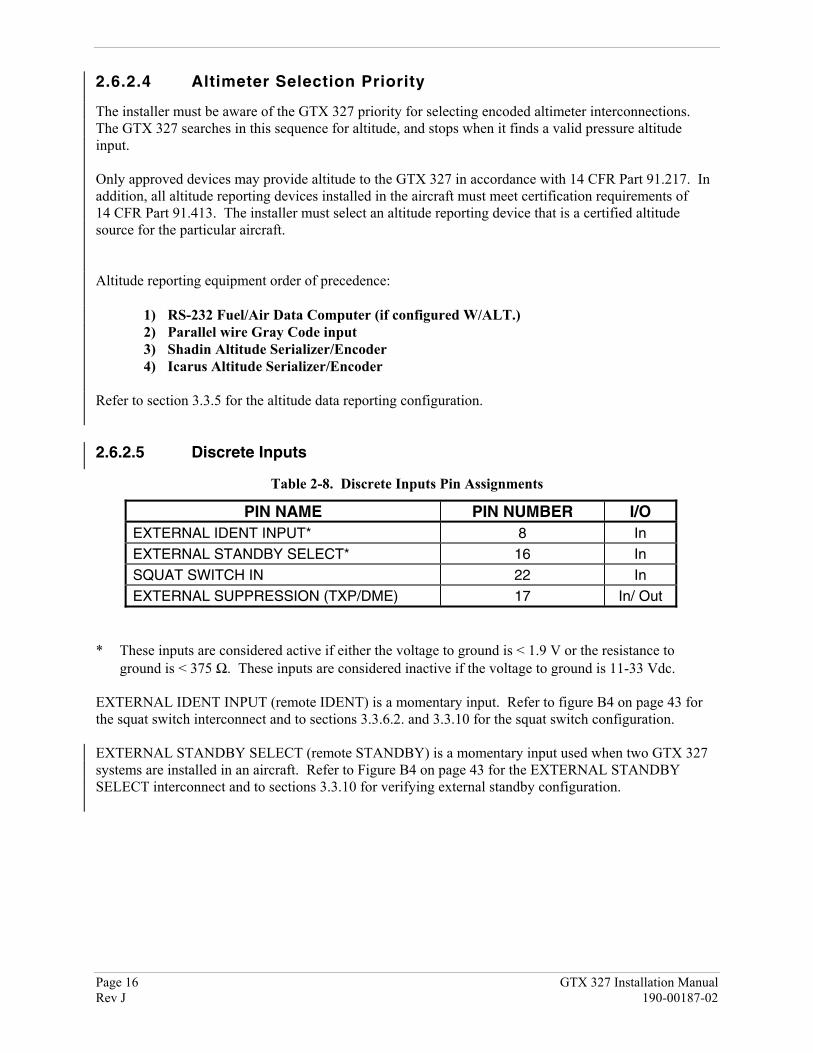
2.6.2.4 Altimeter Selection Priority
The installer must be aware of the GTX 327 priority for selecting encoded altimeter interconnections.The GTX 327 searches in this sequence for altitude, and stops when it finds a valid pressure altitudeinput.
Only approved devices may provide altitude to the GTX 327 in accordance with 14 CFR Part 91.217. Inaddition, all altitude reporting devices installed in the aircraft must meet certification requirements of14 CFR Part 91.413. The installer must select an altitude reporting device that is a certified altitudesource for the particular aircraft.
Altitude reporting equipment order of precedence:
1) RS-232 Fuel/Air Data Computer (if configured W/ALT.)2) Parallel wire Gray Code input3) Shadin Altitude Serializer/Encoder4) Icarus Altitude Serializer/Encoder
Refer to section 3.3.5 for the altitude data reporting configuration.
2.6.2.5 Discrete Inputs
Table 2-8. Discrete Inputs Pin Assignments
PIN NAME PIN NUMBER I/OEXTERNAL IDENT INPUT* 8 InEXTERNAL STANDBY SELECT* 16 InSQUAT SWITCH IN 22 InEXTERNAL SUPPRESSION (TXP/DME) 17 In/ Out
* These inputs are considered active if either the voltage to ground is < 1.9 V or the resistance toground is < 375 Ω. These inputs are considered inactive if the voltage to ground is 11-33 Vdc.
EXTERNAL IDENT INPUT (remote IDENT) is a momentary input. Refer to figure B4 on page 43 forthe squat switch interconnect and to sections 3.3.6.2. and 3.3.10 for the squat switch configuration.
EXTERNAL STANDBY SELECT (remote STANDBY) is a momentary input used when two GTX 327systems are installed in an aircraft. Refer to Figure B4 on page 43 for the EXTERNAL STANDBYSELECT interconnect and to sections 3.3.10 for verifying external standby configuration.

GTX 327 Installation Manual Page 17190-00187-02 Rev J
2.6.3 RS-232 Serial Data Electrical Characteristics
The GTX 327 can be configured to include GPS, Altitude and Airdata data inputs on two RS-232 inputlines. Altitude data supplied to the GTX 327 can be output to the 400/500 Series Garmin products on anRS-232 output line.
Table 2-9. RS-232 Input/Output Pin Assignments
PIN NAME PIN NUMBER I/ORS-232 OUT 1 20 OutRS-232 IN 1 19 InRS-232 IN 2 2 In
The RS-232 outputs conform to EIA Standard RS-232C with an output voltage swing of at least ±5 Vwhen driving a standard RS-232 load. Refer to figure B4 on page 43 for the RS-232 serial datainterconnect and to section 3.3.5 for RS-232 serial data configuration.

Page 18 GTX 327 Installation ManualRev J 190-00187-02
This page intentionally left blank

GTX 327 Installation Manual Page 19190-00187-02 Rev J
3. POST INSTALLATION CONFIGURATION & CHECKOUT PROCEDURE
3.1 AIRCRAFT STATION LICENSING REQUIREMENTS
The Telecommunications Act of 1996, effective February 8, 1996, provides the FCC discretion toeliminate radio station license requirements for aircraft and ships. The GTX 327 installation must complywith current transmitter licensing requirements. To find out the specific details on whether a particularinstallation is exempt from licensing, please see FCC Fact Sheet PR 5000 or contact the FCC by phone at800-322-1117.
If an aircraft license is required, make application for a license on FCC form 404, Application for AircraftRadio Station License. The FCC also has a fax-on-demand service to provide forms by fax at202-418-0177.
The GTX 327 owner accepts all responsibility for obtaining the proper licensing before using thetransponder.
3.2 OPERATION
NOTEThe coverage you can expect from the GTX 327 is limited to line of sight. Lowaltitude or aircraft antenna shielding by the aircraft itself may result in reduced range.Range can be improved by climbing to a higher altitude. It may be possible tominimize antenna shielding by locating the antenna where dead spots are only noticedduring abnormal flight attitudes.
Figure 3-1. GTX 327 Front Panel
NOTESThe GTX 327 should be turned off before starting aircraft engine(s).
If the GTX 327 is configured with Automated Airborne Determination, flightoperation is automatic and not dependent on user mode selection. Whether STBY,ON or ALT is selected on the ground, the transponder annunciation continues toindicate STBY and does not respond to radar or TCAS interrogations. When liftoffis sensed, the unit automatically selects the ALT mode.
Page 20 GTX 327 Installation ManualRev J 190-00187-02
3.2.1 Function Selection Switches
The function selection switches are:
• OFF Powers off the GTX 327. Pressing the STBY, ON or ALT key powers on thetransponder displaying the last active identification code.
• STBY Selects the standby mode. When in standby mode the transponder will not reply toany interrogations.
• ON Selects Mode A. In this mode, the transponder replies to Mode A and Mode Cinterrogations, as indicated by the Reply Symbol (“®”), but the replies do notinclude altitude information.
• ALT Selects Mode A and Mode C. In ALT mode, the transponder replies toidentification and altitude as indicated by the Reply Symbol (“®”). Replies toaltitude interrogations include the standard pressure altitude (29.92 inches Hg.)received from an external altitude source, which is not adjusted for barometricpressure. The ALT mode may be selected in aircraft not equipped with an optionalaltitude encoder; however, the reply signal will not include altitude information.
NOTEAny time the function switch is in the ON or ALT position the transponderbecomes an active part of the Air Traffic Control Radar Beacon System(ATCRBS). The transponder also responds to interrogations from TCASequipped aircraft.
• IDENT Pressing the IDENT key activates the Special Position Identification (SPI) Pulsefor 18 seconds, identifying the transponder return from others on an air trafficcontroller’s screen. During the IDENT period, the word ‘IDENT’ appears in theupper left corner of the display.
• VFR Sets the transponder code to the pre-programmed VFR code selected inConfiguration Mode (set to 1200 at the factory). Pressing the VFR key again willrestore the previous identification code.

GTX 327 Installation Manual Page 21190-00187-02 Rev J
• FUNC Changes the page shown on the right side of the display. Display dataincludes Pressure Altitude, Flight Time, Count Up and Count Down timers.In the Configuration Mode, steps through the function pages.
Pressure Alt: Displays the altitude data supplied to the GTX 327 in feet,flight level format or meters, depending on configurationsetup.
Flight Time: Displays the Flight Time which is controlled as configured onConfiguration #1 page.
Count Up Timer: Controlled by START/STOP and CLR buttons.
Count Down Timer: Controlled by START/STOP, CLR, and CRSR buttons.Count down time entered with 0 – 9 buttons.
Contrast: Controlled by 8 and 9 buttons.
Display Brightness: Controlled by 8 and 9 buttons
• START/ STOP Starts and stops the Count Up, Count Down and Flight Time. In theConfiguration Mode, reverses through the function pages.
• CRSR Activates the change fields for the Count Down timer.
• CLR Resets the Count Up, Count Down and Flight timers. Returns cursor tofourth code digit up to five seconds after code entry is complete.
• 8 Reduces screen Contrast and Display Brightness. Enters the number eightinto the Count Down timer.
• 9 Increases screen Contrast and Display Brightness. Enters the number nineinto the Count Down timer.

Page 22 GTX 327 Installation ManualRev J 190-00187-02
3.2.2 Function Display
PRESSURE ALT Displays the altitude data supplied to the GTX 327 in feet, hundreds offeet (i.e., flight level), or meters, depending on configuration.
FLIGHT TIME Displays the Flight Time, controlled by the START/STOP key or by oneof four airborne sources (squat switch, GPS ground speed recognition,airdata airspeed recognition or altitude increase) as configured duringinstallation. The timer begins when the GTX 327 determines that theaircraft is airborne.
COUNT UP TIMER Controlled by START/STOP and CLR keys.
COUNT DOWN TIMER Controlled by START/STOP, CLR, and CRSR keys. The initialCount Down Time is entered with the 0 – 9 keys.
CONTRAST This page is only displayed if manual contrast mode is selected inConfiguration Mode. Contrast is controlled by the 8 and 9 keys .
DISPLAY This page is only displayed if manual backlighting mode is selected inConfiguration Mode. Backlighting is controlled by the 8 and 9 keys.

GTX 327 Installation Manual Page 23190-00187-02 Rev J
3.2.3 Code Selection
Code selection is done with eight keys (0 - 7) that provide 4,096 active identification codes. Pushing oneof these keys begins the code selection sequence. The new code is not activated until the fourth digit isentered. Pressing the CLR key moves the cursor back to the previous digit. Pressing the CLR key whenthe cursor is on the first digit of the code, or pressing the CRSR key during code entry, removes thecursor and cancels data entry, restoring the previous code. You may press the CLR key up to fiveseconds after code entry is complete to return the cursor to the fourth digit. The numbers 8 and 9 are notused for code entry, only for entering a Count Down time, contrast and display brightness, and dataselection in the Configuration Mode.
NOTEThe selected identification code should be entered carefully, either oneassigned by air traffic control for IFR flight or an applicable VFRtransponder code.
• Important Codes:
1200 VFR code for any altitude in the US (Refer to ICAO standards elsewhere)
2000 VFR code commonly used in Europe (Refer to ICAO standards)
7000 VFR code commonly used in Europe (Refer to ICAO standards)
7500 Hijack code (Aircraft is subject to unlawful interference)
7600 Loss of communications
7700 Emergency
Avoid selecting code 7500 and all codes in the 7600-7777 range. These codes trigger special indicatorsin automated facilities. An aircraft’s transponder code is used for ATC tracking purposes, thereforeexercise care when making routine code changes.
3.3 CONFIGURATION PAGES
With the unit turned off, holding down the FUNC key and pressing one of the power on keys providesaccess to the configuration pages. The FUNC key sequences through the configuration pages. TheSTART/STOP key reverses through the pages, stopping at the first configuration page. The CRSR keyhighlights selectable fields on each page. When a field is highlighted, numeric data entry is performedwith the 0 – 9 keys and list selections are performed with the 8 or 9 keys. Press the CRSR key to acceptchanges. Pressing the FUNC key displays the next configuration page without saving the changes.
Configuration page changes are stored in EEPROM memory. To exit the configuration pages, turn thepower off. Then turn on again (without holding the FUNC key) for normal operation.

Page 24 GTX 327 Installation ManualRev J 190-00187-02
3.3.1 DISPLAY MODE Page
DISPLAY MODE
Selection DescriptionAUTO (Automatic) DEFAULT. The display will automatically change between Positive
mode (during the day) and Negative mode (at night), depending on theambient light level received by the photocell.
NGTV (Negative) The display will always be light characters on a black background,regardless of ambient lighting.
PSTV (Positive) The display will always be black characters on a light background,regardless of ambient lighting.
LEVEL
Sets the ambient light level required for AUTO mode to change between negative and positive display.The higher the number, the brighter the ambient light level required for the change-over. This field has arange of 0 (zero) to 99, and is set to 75 at the factory.
3.3.2 DISPLAY BACKLIGHT Page
BKLT (Backlight)
Selection DescriptionMAN (Manual) Display backlighting is controlled manually by the pilot on the
GTX 327 DISPLAY page. No backlight parameters can be enteredwhen the manual mode is selected.
AUTO (Automatic) DEFAULT. Display backlighting is automatically controlled, basedon the parameters entered on this configuration page. When AUTO isselected, the DISPLAY page does not appear to the pilot when theGTX 327 is operated in normal mode.
LVL (Level)
Shows the current level of display backlighting, based on the lighting input source (lighting bus voltage,or the ambient light if the source is PHOTO) and the settings on this configuration page. This field has arange of 0 (zero) to 999. The level is set by pressing the 8 and 9 keys when MAN mode is selected.When in AUTO mode, the field is for display only.
RSP TIME (Response Time)
Sets the speed with which the brightness responds to ambient light changes (only for AUTO backlightmode). The higher the number, the slower the display responds. This field has a range of 3 to 7, and isset to 4 at the factory.
MIN (Minimum) (Auto Only)
Sets the minimum brightness of the display. The higher the number, the brighter the minimumbrightness. Display minimum brightness has a range of 0 (zero) to 99, and is set to 8 at the factory. It isprudent to verify that display lighting characteristics match those of other equipment in the panel undernight lighting conditions.
DISPLAY MODE Page
DISPLAY BACKLIGHT Page

GTX 327 Installation Manual Page 25190-00187-02 Rev J
BKLT SRCE (Backlight Source) (Auto Only)
Selection DescriptionPHOTO (Photocell) DEFAULT. Backlight level is determined by the ambient light level
as measured by the photocell on the GTX 327.14V Backlight level tracks a 14 volt DC aircraft lighting bus.28V Backlight level tracks a 28 volt DC aircraft lighting bus.5V Backlight level tracks a 5 volt DC aircraft lighting bus.
NOTEIf a lighting bus (any selection other than PHOTO) is selected, and thelighting bus control is turned to its minimum (daytime) setting, the displaybrightness will track the GTX 327 photocell.
SLOPE (Auto Only)
Sets the sensitivity of the display brightness to changes in the input level. The higher the number, thebrighter the display will be for a given increase in the input level. This field has a range of 0 (zero) to 99,and is set to 50 at the factory.
OFFSET (Auto Only)
Adjusts the lighting level up or down for any given input level. This field has a range of 0 (zero) to 99,and is set to 50 at the factory. This may also be used to match lighting curves with other equipment in thepanel.
3.3.3 KEY LIGHTING Page
The key lighting mode is always the same as the displaybacklight mode, so the mode must be changed on the DisplayBacklight configuration page. If the lighting mode is AUTO, then the key lighting parameters can beedited on this page.KEY (Key Lighting)
Selection DescriptionMAN (Manual) Key lighting is controlled manually by the pilot on the GTX 327
DISPLAY page.AUTO (Automatic) Key lighting is automatically controlled based on the parameters
entered on this configuration page.
LVL (Level)
Shows the current level of key lighting, based on the lighting input source (lighting bus voltage, or theambient light if the source is PHOTO) and the settings on this configuration page. This field has a rangeof 0 (zero) to 999. The level is set by pressing the 8 and 9 keys when MAN mode is selected. When inAUTO mode, the field is for display only.
KEY LIGHTING Page

Page 26 GTX 327 Installation ManualRev J 190-00187-02
RSP TIME (Response Time)
Sets the speed with which the brightness responds to ambient light changes (only for AUTO key lightingmode). The higher the number, the slower the key lighting responds. This field has a range of 3 to 7, andis set to 4 at the factory.
MIN (Minimum) (Auto Only)
Sets the minimum brightness of the key lighting. The higher the number, the brighter the minimumbrightness. Key lighting minimum brightness has a range of 0 (zero) to 99, and is set to 8 at the factory.It is prudent to verify that key lighting characteristics match those of other equipment in the panel undernight lighting conditions.
KEY SRCE (Key Lighting Source) (Auto Only)
Selection DescriptionPHOTO (Photocell) DEFAULT. Key lighting level is determined by the ambient light
level as measured by the photocell on the GTX 327.14V Backlight level tracks a 14 volt DC aircraft lighting bus.28V Backlight level tracks a 28 volt DC aircraft lighting bus.5V Backlight level tracks a 5 volt DC aircraft lighting bus.
SLOPE (Auto Only)
Sets the sensitivity of the key lighting brightness to changes in the input level. The higher the number,the brighter the key lighting will be for a given increase in the input level. This field has a range of 0(zero) to 99, and is set to 50 at the factory.
OFFSET (Auto Only)
Adjusts the key lighting level up or down for any given input level. This field has a range of 0 (zero) to99, and is set to 50 at the factory. This may also be used to match lighting curves with other equipment inthe panel.

GTX 327 Installation Manual Page 27190-00187-02 Rev J
3.3.4 CONTRAST CONFIGURATION Page
CONTRAST MODE
Selection DescriptionMAN (Manual) The display contrast is manually adjusted either here or by the pilot
using the GTX 327 CONTRAST page.AUTO (Automatic) DEFAULT. The display contrast is automatically compensated for
temperature and other factors. An offset can be entered in the contrastlevel adjustment described below.
CONTRAST LEVEL ADJUSTMENT
This is a “slider” bar graph control. Use the 8 key to move it further to the left, decreasing the contrastlevel. Use the 9 key to move it to the right, increasing the contrast level. It is set to 50% at the factory.In manual contrast mode, this is a direct adjustment of the display contrast level. In automatic contrastmode, this adjusts the offset to the automatically compensated contrast. Numeric ranges are: contrastlevel (1-63) and contrast offset (0-99; default 50).
CONTRAST CONFIGURATION Page

Page 28 GTX 327 Installation ManualRev J 190-00187-02
3.3.5 RS-232 INPUT/OUTPUT Page
This is the electrical source for the GTX 327 altitude andGPS data input. Refer to paragraph 2.6.2.4 for altimeterdata selection priority.
RS-232 INPUT (Altitude Source, GPS Data)
SELECTION DESCRIPTIONOFF DEFAULT. The altitude code input is not from an RS-232 source.GPS RS-232 ground speed from a GPS device.ICARUS ALT RS-232 serial altitude from an Icarus Instruments 3000.ADC NO ALT RS-232 serial air data information from Shadin ADC 200, 200+, 2000.ADC W/ALT RS-232 serial air data information from Shadin ADC 200, 200+, 2000 plus
altitude data.SHADIN ALT RS-232 serial altitude from Shadin 8800T, 9000T, 9200T.FADC NO ALT RS-232 serial air data from Shadin 9628XX-X family of Air Data
Computers and Fuel/Air Data Computers.FADC W/ALT RS-232 serial air data from Shadin 9628XX-X family of Air Data
Computers and Fuel/Air Data Computers plus altitude data.REMOTE RS-232 serial input remote data. Reserved for future use.
RS-232 OUTPUT (Altitude Out)
SELECTION DESCRIPTIONOFF No RS-232 output from this channel.ICARUS ALT DEFAULT. RS-232 serial altitude from an Icarus Instruments 3000.REMOTE RS-232 serial output remote data. Reserved for future use.
RS-232 INPUT/OUTPUT Page

GTX 327 Installation Manual Page 29190-00187-02 Rev J
3.3.6 OPERATION CONFIGURATION Pages
3.3.6.1 First Configuration Page
VS RATE (Vertical Speed Rate)
This field is the typical vertical speed for climb/descent of the aircraft. This number determines when aclimb or descent arrow is displayed on the PRESSURE ALT page of the GTX 327. The range is 0 (zero)feet per minute to 9999 feet per minute. It is set to 500 fpm at the factory.
FLT TMR (Flight Timer)
Available choices are MANUAL, CLEAR and ACCUMULATE. Selecting CLEAR resets Flight Time tozero and starts the flight timer when lift off is sensed.
Selection DescriptionMANUAL Flight timer START/STOP is controlled manually by the pilot.CLEAR DEFAULT. Automated flight timer START/STOP resets to zero at every
lift off.ACCUMULATE Automated flight timer START/STOP continues counting up at lift off.
VFR ID (VFR Transponder Code)
This field is the four-digit code that will be selected when the user presses the GTX 327 VFR key. In theUnited States, 1200 is the VFR code for any altitude. Many European countries use 7000 as the VFRcode. It is set to 1200 at the factory.
FORMAT (Altitude Format)
This field determines how the pressure altitude will be shown on the GTX 327 display.
Selection DescriptionFLIGHT LVL(Flight Level)
DEFAULT. The pressure altitude is displayed in hundreds of feet.For example, a pressure altitude of 12,300 feet is displayed as “FL123”.
FEET Pressure altitude is displayed in feet.METERS Pressure altitude is displayed in meters.
First Configuration Page
Page 30 GTX 327 Installation ManualRev J 190-00187-02
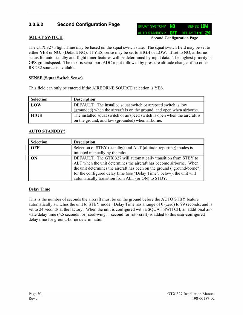
3.3.6.2 Second Configuration Page
SQUAT SWITCH
The GTX 327 Flight Time may be based on the squat switch state. The squat switch field may be set toeither YES or NO. (Default NO). If YES, sense may be set to HIGH or LOW. If set to NO, airbornestatus for auto standby and flight timer features will be determined by input data. The highest priority isGPS groundspeed. The next is serial port ADC input followed by pressure altitude change, if no otherRS-232 source is available.
SENSE (Squat Switch Sense)
This field can only be entered if the AIRBORNE SOURCE selection is YES.
Selection DescriptionLOW DEFAULT. The installed squat switch or airspeed switch is low
(grounded) when the aircraft is on the ground, and open when airborne.HIGH The installed squat switch or airspeed switch is open when the aircraft is
on the ground, and low (grounded) when airborne.
AUTO STANDBY?
Selection DescriptionOFF Selection of STBY (standby) and ALT (altitude-reporting) modes is
initiated manually by the pilot.ON DEFAULT. The GTX 327 will automatically transition from STBY to
ALT when the unit determines the aircraft has become airborne. Whenthe unit determines the aircraft has been on the ground ("ground-borne")for the configured delay time (see "Delay Time", below), the unit willautomatically transition from ALT (or ON) to STBY.
Delay Time
This is the number of seconds the aircraft must be on the ground before the AUTO STBY featureautomatically switches the unit to STBY mode. Delay Time has a range of 0 (zero) to 99 seconds, and isset to 24 seconds at the factory. When the unit is configured with a SQUAT SWITCH, an additional air-state delay time (4.5 seconds for fixed-wing; 1 second for rotorcraft) is added to this user-configureddelay time for ground-borne determination.
Second Configuration Page

GTX 327 Installation Manual Page 31190-00187-02 Rev J
3.3.7 AIRCRAFT TYPE Page
SELECTION DESCRIPTIONAC TYPE UNKNOWN, <15.5K, >=15.5K, or ROTOR.
AIRCRAFT TYPE
Used for Automated Airborne Determination (time to STBY, required airspeed, ground speed). Sets theAIRCRAFT TYPE to ROTOR, to a weight of less than 15,500 pounds, more than or equal to 15,500pounds, or unknown weight. Defaults to less than or equal to 15,500 pounds.
3.3.8 RS-232 INPUT VIEW Page
Depending on the selected inputs on Channel 1 and Channel 2, this page displays the informationreceived on the channel. If GPS is selected as an input, ground speed (GSPD), latitude (LAT), longitude(LON) and track (TRK) can be viewed.
If ICARUS or SHADIN-ALT is selected as an input, pressure altitude (PALT) can be viewed.
If SHADIN-FADC or SHADIN-ADC is selected as an input, true or static air temperature (SAT), outsideor total air temperature (TAT), indicated air speed (IAS), true air speed (TAS), density altitude (DALT),pressure altitude (PALT), current barometric pressure (BARO) and vertical speed (VSPD) can be viewed.
3.3.9 GRAY CODE INPUT Page
Information on this page may aid in installationtroubleshooting. There are no user inputs or operations onthis page.
GRAY CODE
This field shows the status (1 = ground, 0 = open) of each of the ten gray code altitude inputs. Thisinformation may aid in installation troubleshooting. This page is not used in systems that contain serialaltitude input.
DECODED ALTITUDE
This field displays the gray code altitude input in feet. Verify that it is the correct altitude.
AIRCRAFT TYPE Page
RS-232 INPUT VIEW Page
GRAY CODE INPUT Page

Page 32 GTX 327 Installation ManualRev J 190-00187-02
3.3.10 EXTERNAL SWITCH Page
Displays the state of the external switch discrete inputs.
IDENT
Displays the state of the EXTERNAL IDENT discrete input. The box is filled when EXTERNALIDENT is grounded.
STANDBY
Displays the state of the EXTERNAL STANDBY discrete input. The box is filled when EXTERNALSTANDBY is grounded.
SQUAT
Displays the state of the SQUAT SWITCH input. The box is filled when the SQUAT SWITCH input isactive (the aircraft is on the ground as configured on the Second Configuration page).
3.3.11 ANALOG INPUT Page
The Analog to Digital Converter (ADC) counts are shown on the display, providing troubleshooting data.There are no user inputs or operations on this page.
14/5V LTG
Displays the current 14 Volt lighting bus ADC level.
PHOTO
Displays the current photocell ADC level.
LCD TEMP
Displays the current LCD temperature ADC level.
28V LTG
Displays the current 28 Volt lighting bus ADC level.
REPLY
Displays the current reply active ADC level.
UNIT TEMP
Displays the current unit temperature ADC level.
EXTERNAL SWITCH Page
ANALOG INPUT Page

GTX 327 Installation Manual Page 33190-00187-02 Rev J
APPENDIX A
CERTIFICATION DOCUMENTS
A.1 Continued Airworthiness
Other than for regulatory periodic functional checks, maintenance of the GTX 327 is “on condition” only.Refer to the GTX 327 Maintenance Manual. Periodic maintenance of the GTX 327 is not required.
This section provides assistance to the installing agency in preparing Instructions for ContinuedAirworthiness (ICA) in response to Bulletin Number HBAW 98-18, “Checklist for Instructions forContinued Airworthiness for Major Alterations Approved Under the Field Approval Process”, effective10/7/98.
Aviation Authority approved installers are hereby granted permission to reference appropriate serviceinstructions and excerpts from this Installation Manual to accomplish the Instructions for ContinuedAirworthiness. This permission does not construe suitability of the documents. It is the applicant’sresponsibility to determine the suitability of the documents for the ICA.
Following is a suggested ICA for a Garmin GTX 327 unit installation. Some of the checklist items do notapply, in which case they should be marked “N/A” (Not Applicable).
INSTRUCTIONS FOR CONTINUED AIRWORTHINESS, GARMIN GTX 327
1. Introduction[Aircraft that has been altered: Registration (N-) number, Make, Model and Serial Number]
Content, Scope,Purpose and Arrangement: This document identifies the Instructions for Continued Airworthiness
for the modification of the above aircraft by installation of a GarminGTX 327.
Applicability: Applies to aircraft altered by installation of the Garmin GTX 327.Definitions/Abbreviations: None, N/A.Precautions: None, N/A.Units of Measurement: None, N/A.Referenced Publications: Garmin GTX 327 Installation Manual, P/N 190-00187-01
Garmin GTX 327 Maintenance Manual, P/N 190-00187-05Garmin STC # SA00870WI.Garmin GTX 327 Pilot’s Guide, P/N 190-00187-00.
Distribution: This document should be a permanent aircraft record.
2. Description of the AlterationInstallation of the Garmin GTX 327, with interface to Encoding Altimeter or Blind Encoder. Refer tosection 2.4 and Appendix B of this manual for interconnect information. Antenna installation,removal and replacement should be in accordance with applicable provisions of AC 43.13-1B andAC 43.13-2A.

Page 34 GTX 327 Installation ManualRev J 190-00187-02
3. Control, Operation InformationRefer to the GTX 327 Pilot’s Guide, Garmin P/N 190-00187-00.
4. Servicing InformationN/A
5. Maintenance InstructionsMaintenance of the GTX 327 is ‘on condition’ only. Periodic maintenance is not required. Refer tothe GTX 327 Maintenance Manual.
6. Troubleshooting InformationRefer to the GTX 327 Maintenance Manual.
7. Removal and Replacement InformationRefer to section 2.4 of this manual. If the unit is removed and reinstalled, a functional check of theequipment should be conducted in accordance with section 3.2 of this manual.
8. DiagramsRefer to Appendix B of this manual.
9. Special Inspection RequirementsN/A
10. Application of Protective TreatmentsN/A
11. Data: Relative to Structural FastenersAntenna installation, removal and replacement should be in accordance with applicable provisions ofAC 43.13-1A and AC 43.13-2A. Also, refer to section 2.3 of this manual.
12. Special ToolsN/A
13. This Section is for Commuter Category Aircraft OnlyA. Electrical loads: Refer to section 1.3 of this manual.B. Methods of balancing flight controls: N/A.C. Identification of primary and secondary structures: N/A.D. Special repair methods applicable to the airplane: Antenna installation, removal, and replacementshould be in accordance with applicable provisions of AC 43.13-1B and AC 43.13-2A.
14. Overhaul PeriodNo additional overhaul time limitations.
15. Airworthiness Limitation SectionN/A.

GTX 327 Installation Manual Page 35190-00187-02 Rev J
16. RevisionTo revise this ICA, a letter must be submitted to the local FSDO with a copy of the revised FAAForm 337, and revised ICA. The FAA inspector accepts the change by signing Block 3 and includingthe following statement:
“The attached revised/new Instructions for Continued Airworthiness (date ______) for the aboveaircraft or component major alteration have been accepted by the FAA, superseding the Instructionsfor Continued Airworthiness (date ______).”
17. AssistanceFlight Standards Inspectors have the resources to respond to questions regarding the ICA.
18. Implementation and Record KeepingFor major alterations performed in accordance with FAA field approval policy, the owner/operatoroperating under Part 91 is responsible for ensuring that the ICA is made part of the applicable section91.409 inspection program for their aircraft. This is accomplished when a maintenance entry is madein the aircraft’s maintenance record in accordance with section 43.9. This entry records the majoralteration and identifies the original ICA location (e.g., Block 8 of FAA Form 337, dated ______)along with a statement that the ICA is now part of the aircraft’s inspection/maintenance requirements.

Page 36 GTX 327 Installation ManualRev J 190-00187-02
A.2 ENVIRONMENTAL QUALIFICATION FORMNOMENCLATURE: GTX 327 Airborne ATC Transponder EquipmentTYPE/MODEL/PART NO.: 010-00188-( ), which includes 011-00490-( )TSO/JTSO COMPLIANCE: TSO - C74c Class 1A, JTSO - C74c Class 1AMANUFACTURER'S SPECIFICATION AND/OR OTHERAPPLICABLE SPECIFICATION: 004-00070-00 Minimum Performance Specification
MANUFACTURER: Garmin International
ADDRESS: 1200 E 151st St, Olathe, Kansas 66062
Conditions RTCA DO-160DSection
Description of Conducted Tests
Temperature and Altitude 4.0 Equipment tested to Categories A1 & D1 except asnoted
Low Temperature 4.5.1
High Temperature 4.5.2. & 4.5.3
In-Flight Loss of Cooling 4.5.4 Cooling air not required.
Altitude 4.6.1
Decompression 4.6.2
Overpressure 4.6.3
Temperature Variation 5.0 Equipment tested to Category C
Humidity 6.0 Equipment tested to Category A
Shock 7.0 Equipment tested to Category B
Vibration 8.0 Equipment tested in each aircraft type to aircraft zone2. Aircraft Type 2 and 6 were tested to Category S2,Vibration level B2. Aircraft Type 3, 4 and 5 weretested to Category S, Vibration level M.
Note: Vibration level M modified to increase levelto RTCA DO-160C Curve N for Helicopters asfollows-0.1 inches peak-to-peak double amplitudefrom 5 Hz to 17 Hz, 1.5 g-Pk from 17 Hz to 500 Hz.

GTX 327 Installation Manual Page 37190-00187-02 Rev J
Conditions RTCA DO-160DSection
Description of Conducted Tests
Explosion 9.0 Equipment identified as Category X, no test required
Waterproofness 10.0 Equipment identified as Category X, no test required
Fluids Susceptibility 11.0 Equipment identified as Category X, no test required
Sand and Dust 12.0 Equipment identified as Category X, no test required
Fungus 13.0 Equipment identified as Category X, no test required
Salt Spray 14.0 Equipment identified as Category X, no test required
Magnetic Effect 15.0 Equipment tested to Class Z
Power Input 16.0 Equipment tested to Category A
Voltage Spike 17.0 Equipment tested to Category A
Audio FrequencySusceptibility
18.0 Equipment tested to Category B
Induced SignalSusceptibility
19.0 Equipment tested to Category A
Radio FrequencySusceptibility
20.0 Equipment tested for conducted susceptibility toCategory T, radiated susceptibility to Category T,and pulse test to Category T.
Radio Frequency Emission 21.0 Equipment tested to Category B, Equipment tested toCategory M up to 2 GHz.
Lightning Induced TransientSusceptibility
22.0 Equipment identified as Category XXXX, no testrequired
Lightning Direct Effects 23.0 Equipment identified as Category X, no test required
Icing 24.0 Equipment identified as Category X, no test required
Electrostatic Discharge 25.0 Equipment identified as Category X, no test required
Remarks: In the Y-Axis vibration sweep, there were two critical frequencies identified very closetogether at 160 Hz and 181 Hz. At the end of the vibration test cycle the two frequencies hadcombined into one frequency at 179 Hz. There was no change in unit performance.

Page 38 GTX 327 Installation ManualRev J 190-00187-02
This page intentionally left blank

GTX 327 Installation Manual Page 39190-00187-02 Rev J
APPENDIX B
ASSEMBLY AND INSTALLATION DRAWINGS
B.1 GENERAL
This section contains the following installation drawings:
• B1, GTX 327 Outline Drawing• B2, GTX 327 Connector/Rack Kit Assembly Drawing• B3, GTX 327 Recommended Panel Cutout Dimensions• B4, GTX 327 Interconnect Wiring Diagram• B5, Dual TXP Interconnect Wiring Diagram, Encoding Altitude Connections

Page 40 GTX 327 Installation ManualRev J 190-00187-02
This page intentionally left blank

GTX
327 Installation Manual
Page 41 (Page 42 blank)190-00187-02
Rev J
Figure B1. G
TX 327 O
UTLIN
E DR
AW
ING

GTX
327 Installation Manual
Page 43 (Page 44 blank)190-00187-02
Rev J
Figure B
2. GT
X 327 C
ON
NE
CT
OR
/RA
CK
KIT
AS
SE
MB
LY D
RA
WIN
G
SEE NOTE
SEE NOTE
THESE HOLES NOT USED
NOTE:KIT W
ILL INCLUDE EITHER ITEM 6 OR ITEM 12.REFER TO SECTION 2 FOR ADDITIONAL INFORMATION.
ItemPart Num
berDescription
Qty1
211-63234-12SCREW
, 4-40 X .75, FLHP, SS/P2
2212-20014-00
WSHR, FLAT, NON-STD, SS
13
232-00013-01SNAP RING, EXT, 7/16
14
330-00220-25BACKSHELL, D-SUB, M
ETAL, 251
5330-00184-25
CONN., D-SUB, MIL CRP, SCKT, 25
1SEE NOTE
6330-00198-00
CONN. BNC, MALE BLINDM
ATE1
NOT SHOWN
336-00022-00CONT. SCKT, M
IL CRP, SIZE 2025
NOT SHOWN
336-00023-00CONT. SCKT, M
IL CRP, SIZE 20-185
NOT SHOWN
312-00005-05TUBING, HT SHRINK
2.3IN7
115-00285-00INSTALL RACK
18
125-00032-02BACK PLATE
19
211-60234-06SCREW
, 4-40X.187, PHP, SS/P4
10125-00046-00
NUT PLATE, D-SUB, 25 POS2
11234-10002-00
SPRING WASHER
1SEE NOTE
12330-00326-00
RF ADAPTER1

GTX
327 Installation Manual
Page 45 (Page 46 blank)190-00187-02
Rev J
Figure B3 G
TX 327 R
ECO
MM
END
ED PA
NEL C
UTO
UT D
IMEN
SION
S

GTX
327 Installation Manual
Page 47 (Page 48 blank)190-00187-02
Rev J
Figure B4 G
TX 32 TY
PICA
L INTER
CO
NN
ECT W
IRIN
G D
IAG
RA
M

GTX
327 Installation Manual
Page 49 (Page 50 blank)190-00187-02
Rev J
Figure B5 D
UA
L TXP IN
TERC
ON
NEC
T WIR
ING
DIA
GR
AM
, ENC
OD
ING
ALTITU
DE C
ON
NEC
TION
S

GTX 327 Installation Manual Page 51190-00187-02 Rev J
APPENDIX C
STC PERMISSION
Consistent with N8110.69 or Order 8110.4, Aviation Authority approved installers are hereby grantedpermission to use STC #SA00870WI data to modify aircraft.

Page 52 GTX 327 Installation ManualRev J 190-00187-02