guam grn sw implementation plan final draft 3-15-10 · development of the transportation storm...
TRANSCRIPT

GRN Storm Water Implementation Plan Issue Date: March 2010 Version: Draft Guam DPW Parsons
GUAM_GRN_SW_IMPLEMENTATION_PLAN FINAL_DRAFT_3-15-10.DOC.
DRAFT Storm Water Implementation Plan
For the Guam Road Network
March 2010
Submitted to
Guam Department of Public Works
Submitted by
PARSONS TRANSPORTATION GROUP, Inc
Preliminary – Not for Construction, Subject to Independent Verification Prior to Final Design

GRN Storm Water Implementation Plan Issue Date: March 2010 Version: Draft Guam DPW Parsons
GUAM_GRN_SW_IMPLEMENTATION_PLAN FINAL_DRAFT_3-15-10.DOC i
PREFACE
The Guam Road Network (GRN) is a collection of highway improvement projects that are being negotiated between Guam Department of Public Works (DPW) and the Department of Defense (DOD) as recommended improvements for the proposed military build up. Some of these projects are in addition to the project currently listed in the Territory Transportation Improvement Plan. The DOD proposal would reprioritize these projects to accommodate the military build-up. This Project Report evaluates the collective impact that these projects could have on the water resources of Guam and proposes improvements to mitigate these impacts. The GRN projects primarily include pavement strengthening projects which generally do not increase the overall impervious area. The work effort includes improvements along Routes 1, 2A, 3, 3A, 5, 8, 9, 10, 11, 15, 16, 25, 26, 27, 28 and Chalan Lujana. The projects also include improvements to 8 bridges along Route 1 in the Apra Harbor area.
Parsons prepared this Draft Storm Water Implementation Plan for the GRN as part of the development of the Transportation Storm Water Drainage Manual1 (TSDM) and the Storm Water Drainage Master Plan development for the Guam Department of Public Works. The Storm Water Implementation Plan for the GRN (Plan) provides source control and treatment control best management practices (BMPs) to be used for the various GRN projects. This Plan includes a suite of treatment BMPs that can be used throughout the GRN. BMP selection, discussed herein, considers pollutants of concern, right of way constraints, maintainability, existing drainage infrastructure, proximity to wetlands, as well as existing treatment devices.
1 This Manual is in the draft development stage.
GRN Storm Water Implementation Plan Issue Date: March 2010 Version: Draft Guam DPW Parsons
GUAM_GRN_SW_IMPLEMENTATION_PLAN FINAL_DRAFT_3-15-10.DOC ii
CONTENTS
PREFACE ii ACRONYMS v SECTION 1 INTRODUCTION 1-1
1.1 Background 1-1 1.2 Report Objectives 1-15 1.3 Report Organization 1-15
SECTION 2 HYDROLOGIC SETTING 2-1 2.1 Watershed Characteristics 2-1 2.2 Surface Water in North Guam 2-1 2.3 Surface Water in South Guam 2-3
SECTION 3 STORM WATER REGULATORY MANDATES, COORDINATION AND IMPLEMENTATION 3-1
3.1 Storm Water Regulations 3-1 3.2 Regulatory Agency Coordination Process 3-2 3.2.1 Design/Build Project Phases 3-3
SECTION 4 WATER POLLUTION CONTROL STRATEGY 4-1 4.1 Construction 4-1 4.2 Post-Construction 4-1 4.2.1 Source Control 4-1 4.2.2 Treatment Control 4-2 4.2.3 Treatment BMP Design 4-2 4.3 Types of Treatment Best Management Practices 4-4
SECTION 5 POLLUTION SOURCE CONTROL 5-1 5.1 Reduction of Impacts from Flow Changes 5-1 5.2 Preservation of Existing Vegetation 5-1 5.3 Concentrated Flow Conveyance Systems 5-1 5.4 Slope and Surface Protection Systems 5-2
SECTION 6 POLLUTION TREATMENT CONTROL 6-1 SECTION 7 GRN STORMWATER MANAGEMENT CONCEPTS 7-1
7.1 Overall Concept 7-1 7.2 Project Categories 7-1 7.3 GRN Onsite Drainage Characteristics 7-10 7.3.1 North Guam 7-10 7.3.2 South Guam 7-11 7.4 GRN Offsite Drainage Characteristics 7-12 7.4.1 North Guam 7-12 7.4.2 South Guam 7-12 7.5 GRN Storm Water Management Summary 7-13
SECTION 8 REFERENCES 8-1

GRN Storm Water Implementation Plan Issue Date: March 2010 Version: Draft Guam DPW Parsons
GUAM_GRN_SW_IMPLEMENTATION_PLAN FINAL_DRAFT_3-15-10.DOC iii
APPENDICES A GRN Project Spreadsheet B Existing Infiltration Basin Site Maps C GRN Overview Map D FEMA Maps E Design Guidelines - Biofiltration Strips and Swales F Bridge Replacement Project Data
List of Figures Figure 1 — GRN Location Map 1-1 Figure 2 — North GRN 1-3 Figure 3 — South GRN 1-4 Figure 4 — North Guam Typical Roadway Cross-Section 2-1 Figure 5 — Harmon Sink at Rte 1 2-2 Figure 6 — Tamuning Drainageway Outlet 2-3 Figure 7 — Offsite Culvert Outlets along Rte 1 at Agana Bay Coastline 2-4 Figure 8 — Culvert Outlet North of Agana River 2-4 Figure 9 — Historic Hourly Rainfall Depths 4-3 Figure 10— Sample Catch Basin Retrofit 4-6 Figure 11— Sample Flow Splitter 4-7 Figure 12— Guam Road Network Water Quality Classification Map 6-2 Figure 13— North GRN Corridor Identification 7-8 Figure 14— South GRN Corridor Identification 7-9 Figure 15— BMP Concept Tamuning Drainageway - 1 7-11 Figure 16— BMP Concept Tamuning Drainageway - 2 7-11 Figure 17— Coastal Erosion Protection Along Rte 1 7-12 Figure 18— Route 1 Flood Prone Area – Apra Harbor 7-13
List of Tables Table 1— GRN Project Components 1-1 Table 2— Work Type Summary of GRN Projects 1-2 Table 3— Report Organization 1-5 Table 4— Summary of Infiltration Basins along GRN (North Guam) 2-2 Table 5— Agency Required Permits and Clearances 3-4 Table 6— Summary of GRN Projects 7-3 Table 7— Summary of GRN Storm Water Management Components 7-14
GRN Storm Water Implementation Plan Issue Date: March 2010 Version: Draft Guam DPW Parsons
GUAM_GRN_SW_IMPLEMENTATION_PLAN FINAL_DRAFT_3-15-10.DOC iv
ACRONYMS
BMPs best management practices cfs cubic feet per second CLOMR Conditional Letter of Map Revision DOD Department of Defense DPW Department of Public Works ESCP Erosion and Sediment Control Plan FEMA Federal Emergency Management Agency FIRM Flood Insurance Rate Map fps feet per second GSRDs gross solids removal devices GEPA Guam Environmental Protection Agency GRN Guam Road Network GTIP Guam Transportation Improvement Program HA hydrologic area HSAs hydrologic sub-areas LOMR Letter of Map Revision MCTT multi-chambered treatment trains MEP maximum extent practicable NB northbound NGL Northern Guam Lens NPDES National Pollutant Discharge Elimination System PDF Project Design Feature SB southbound SWMM Stormwater Management Model SWPPP Stormwater Pollution Prevention Plan TDC Targeted Design Constituent TMDL Total Maximum Daily Load TSS total suspended solids US EPA U.S. Environmental Protection Agency VFS vault flow splitter WQF water quality flow WQV water quality volume

This page intentionally left blank

GRN Storm Water Implementation Plan Issue Date: March 2010 Version: Draft Guam DPW Parsons
GUAM_GRN_SW_IMPLEMENTATION_PLAN FINAL_DRAFT_3-15-10.DOC 1-1
SECTION 1 INTRODUCTION
1.1 BACKGROUND
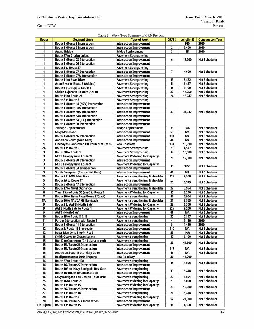
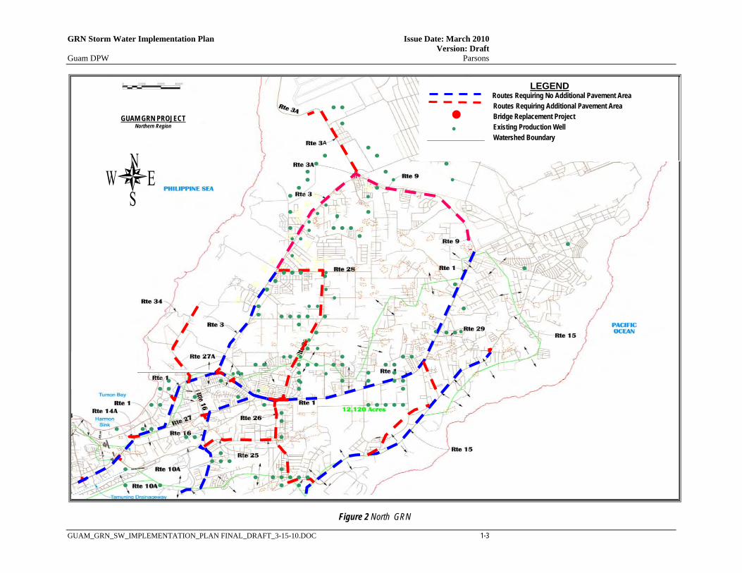
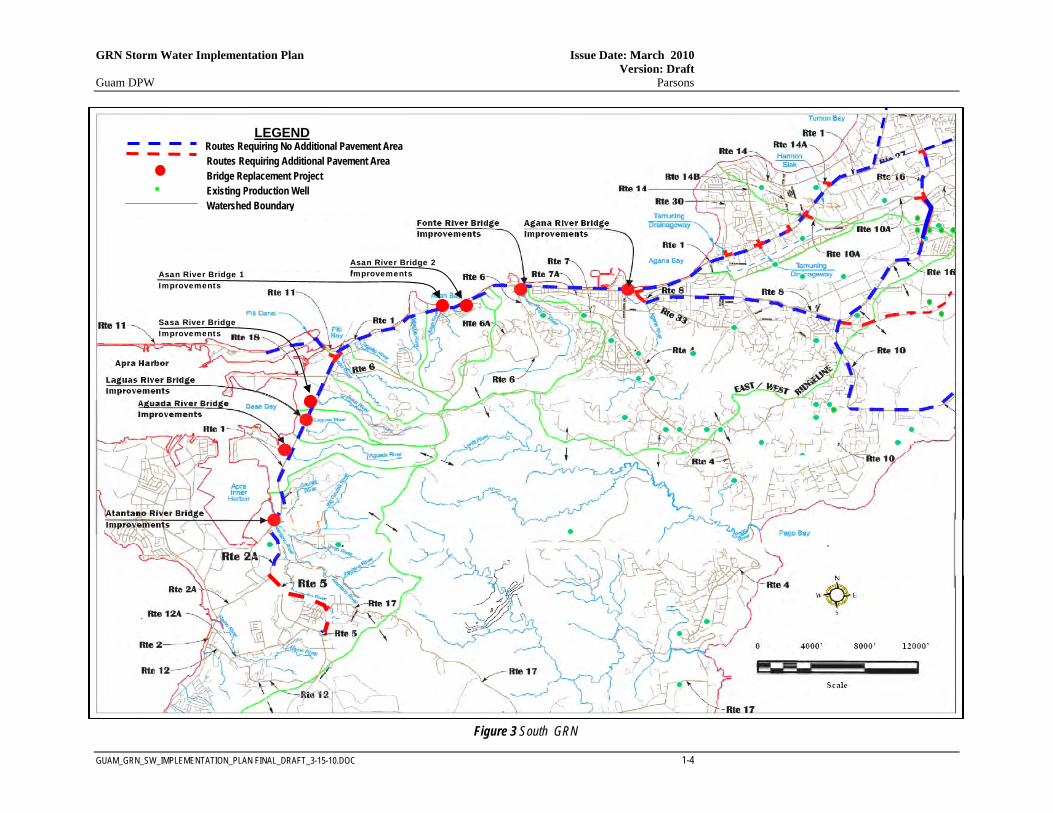
The purpose of this section is to provide a detailed description of the water resource environment that would be impacted by the roadway improvements that would support the relocation of U.S. Marines to Guam. The proposed roadway improvements are collectively referred to as the Guam Road Network (GRN), a connected action to the relocation activity. Figure 1 shows a location map of the approximate area in which the GRN will be constructed2. As shown, Guam is a small island with a coast line of only 110 miles. The major components of the proposed GRN projects are indicated in Table 1. Figures 2 and 3 on the following pages show the proposed corridors of the GRN with respect to the hydrologic regimes throughout the island. Table 2 identifies the main projects and Work Types included in the GRN along with the proposed construction scheduling for the high priority projects. As shown, the work effort includes improvements along Routes 1, 2A, 3, 3A, 5, 8, 9, 10, 11, 15, 16, 25, 26, 27, 28, Chalan Lujana along with improvements to 8 bridges along Route 1 in the Apra Harbor area. Appendix A provides a preliminary project construction schedule, the project requirements and a brief description for each project.
Table 1 - GRN Project Components
2 For simplicity, this document divides the GRN into South and North areas, only. Portions of the central area, which is designated in the DEIS, have been subdivided into the North GRN Project Area and the South GRN Project Area as shown in Figure 1.
Type of Work General Scope Elements Pavement strengthening, no shoulder widening Pavement rehabilitation without increasing exist pavement footprint (impervious area). Pavement strengthening & shoulder widening Pavement rehabilitation with a minor increase in impervious area. Road widening for capacity increase Roadway improvements with an increase in impervious area.
Intersection improvements Reconfiguration of one or more streets; addition of turning lanes; pavement widening; clearing and grading; and an increase in impervious area.
Bridge Improvements Beam, pier wall, wingwall and/or deck rehabilitation or replacement with upstream and/or downstream channel erosion control.
New Roadways New paved roads with increase in impervious area.
North GRN Project Area
South GRN Project Area
Figure 1: GRN Location Map
Guam Road Network
Guam Road Network
2 Cen
tral A
rea
GRN Storm Water Implementation Plan Issue Date: March 2010 Version: Draft Guam DPW Parsons
GUAM_GRN_SW_IMPLEMENTATION_PLAN FINAL_DRAFT_3-15-10.DOC 1-2
Table 2 – Work Type Summary of GRN Projects Route Segment Limits Type of Work GRN # Length (ft) Construction Year
1 Route 1 / Route 8 Intersection Intersection Improvement 1 940 2010 1 Route 1 / Route 3 Intersection Intersection Improvement 2 2,400 2010 1 Agana Bridge Bridge Replacement 3 85 2010 1 Route 27 to Chalan Lujana Pavement Strengthening
6 18,200 Not Scheduled 1 Route 1 / Route 28 Intersection Intersection Improvement 1 Route 1 / Route 26 Intersection Intersection Improvement 1 Route 3 to Route 27 Pavement Strengthening
7 4,600 Not Scheduled 1 Route 1 / Route 27 Intersection Intersection Improvement 1 Route 1 / Route 27A Intersection Intersection Improvement 1 Route 11 to Asan River Pavement Strengthening 13 8,472 Not Scheduled 1 Asan River to Route 6 (Adelup) Pavement Strengthening 14 6,437 Not Scheduled 1 Route 6 (Adelup) to Route 4 Pavement Strengthening 15 9,100 Not Scheduled 1 Chalan Lujana to Route 9 (AAFB) Pavement Strengthening 23 14,250 Not Scheduled 1 Route 11 to Route 2A Pavement Strengthening 24 16,247 Not Scheduled 1 Route 8 to Route 3 Pavement Strengthening
33 31,647 Not Scheduled
1 Route 1 / Route 14 (NSV) Intersection Intersection Improvement 1 Route 1 / Route 14A Intersection Intersection Improvement 1 Route 1 / Route 10A Intersection Intersection Improvement 1 Route 1 / Route 14B Intersection Intersection Improvement 1 Route 1 / Route 14 (ITC) Intersection Intersection Improvement 1 Route 1 / Route 30 Intersection Intersection Improvement 1 7 Bridge Replacements Bridge Replacement 35 364 Not Scheduled 1 Navy Main Base Intersection Improvement 50 N/A Not Scheduled 1 Route 1 / Route 16 Intersection Intersection Improvement 124 N/A Not Scheduled 1 Anderson South (Main Gate) Intersection Improvement 44 N/A Not Scheduled 1 Finegayan Connection Off Route 1 at Rte 16 New Roadway 124 18,910 Not Scheduled
2A Route 1 to Route 5 Pavement Strengthening 26 4,577 Not Scheduled 3 Route 28 to Route 1 Pavement Strengthening 8 13,500 Not Scheduled 3 NCTS Finegayan to Route 28 Pavement Widening for Capacity 9 12,300 Not Scheduled 3 Route 3 / Route 28 Intersection Intersection Improvement 3 NCTS Finegayan to Route 9 Pavement Widening for Capacity 10 3750 Not Scheduled 3 Route 3 / Route 3A Intersection Intersection Improvement 3 South Finegayan (Residential Gate) Intersection Improvement 41 N/A Not Scheduled
3A Route 3 to NWF Main Gate Pavement strengthening & shoulder 125 9,500 Not Scheduled 5 Route 2A to Route 17 Pavement strengthening & shoulder 25 6,379 Not Scheduled 5 Route 5 / Route 17 Intersection Intersection Improvement 5 Route 17 to Naval Ordnance Pavement strengthening & shoulder 27 3,954 Not Scheduled 8 Tiyan Pkwy/Route 33 (east) to Route 1 Pavement Widening for Capacity 16 8,290 Not Scheduled 8 Route 10 to Tiyan Pkwy/Route 33(east) Pavement strengthening 17 7,904 Not Scheduled
8A Route 16 to NAVCAMS Barrigada Pavement strengthening & shoulder 31 8,865 Not Scheduled 9 Route 3 to AAFB (North Gate) Pavement Widening for Capacity 22 6,300 Not Scheduled 9 AAFB North Gate to Route 1 Pavement Widening for Capacity 22a 9,200 Not Scheduled 9 AAFB (North Gate) Intersection Improvement 42 N/A Not Scheduled
10 Route 15 to Route 8 & 16 Pavement strengthening 30 7,847 Not Scheduled 11 Port to Intersection with Route 1 Pavement strengthening 4 9,150 2010 11 Route 1 / Route 11 Intersection Intersection Improvement 5 1,480 2010 12 Route 2/ Route 12 Intersection Intersection Improvement 110 N/A Not Scheduled 12 Naval Munitions Site @ Rte 5 Intersection Improvement 52 N/A Not Scheduled 15 Smith Quarry to Chalan Lujana Pavement strengthening 12 6,100 Not Scheduled 15 Rte 10 to Connector (Ch Lujana to end) Pavement strengthening 32 41,500 Not Scheduled 15 Route 15 / Route 26 Intersection Intersection Improvement 15 Route 15 / Route 29 Intersection Intersection Improvement 117 N/A Not Scheduled 15 Anderson South (Secondary Gate) Intersection Improvement 46 N/A Not Scheduled 15 Realignment onto DOD Property New Roadway 36 11,200 16 Route 27 to Route 10A Pavement strengthening 18 4,505 Not Scheduled 16 Route 16 / Route 27 Intersection Intersection Improvement 16 Route 10A to Navy Barrigada Res Gate Pavement strengthening 19 5,448 Not Scheduled 16 Route 16/ Route 10A Intersection Intersection Improvement 16 Navy Barrigada Res Gate to Route 8/10 Pavement strengthening 20 8,691 Not Scheduled 25 Route 16 to Route 26 Pavement Widening for Capacity 29 8,050 Not Scheduled 26 Route 1 to Route 15 Pavement Widening for Capacity 28 12,900 Not Scheduled 26 Route 26 / Route 25 Intersection Intersection Improvement 27 Route 1 to Route 16 Pavement strengthening 21 5,448 Not Scheduled 28 Route 1 to Route 3 Pavement Widening for Capacity 57 21,000 Not Scheduled 28 Route 28 / Route 27A Intersection Intersection Improvement
Ch Lujana Route 1 to Route 15 Pavement Widening for Capacity 11 4,350 Not Scheduled
GRN Storm Water Implementation Plan Issue Date: March 2010 Version: Draft Guam DPW Parsons
GUAM_GRN_SW_IMPLEMENTATION_PLAN FINAL_DRAFT_3-15-10.DOC 1-3
Figure 2 North GRN
LEGEND Routes Requiring No Additional Pavement Area Routes Requiring Additional Pavement Area Bridge Replacement Project
Existing Production Well Watershed Boundary
GUAM GRN PROJECT Northern Region
A
GRN Storm Water Implementation Plan Issue Date: March 2010 Version: Draft Guam DPW Parsons
GUAM_GRN_SW_IMPLEMENTATION_PLAN FINAL_DRAFT_3-15-10.DOC 1-4
.
Figure 3 South GRN
LEGEND Routes Requiring No Additional Pavement Area Routes Requiring Additional Pavement Area Bridge Replacement Project
Existing Production Well Watershed Boundary
Asan River Bridge 1 Improvements
Asan River Bridge 2 Improvements
Sasa River Bridge Improvements

GRN Storm Water Implementation Plan Issue Date: March 2010 Version: Draft Guam DPW Parsons
GUAM_GRN_SW_IMPLEMENTATION_PLAN FINAL_DRAFT_3-15-10.DOC 1-5
1.2 REPORT OBJECTIVES
This report presents the stormwater management strategy for the GRN. In general, it includes descriptions of the proposed runoff interception and conveyance systems, the water pollution source control elements, and the water pollution treatment and recharge control facilities to be used to mitigate potential water resource impacts. The objective of the report is to:
• Develop an understanding of the appropriate storm water management practices for the GRN projects;
• Develop an understanding of the existing water quality control elements and the impact of the GRN projects on these existing elements;
• Develop an understanding of construction practices, construction monitoring, and construction permitting for activities required for the GRN projects;
• Develop a permitting and project schedule for the GRN projects; • Develop a strategy for achieving early agreement among jurisdictional agencies on
the storm water management approach through design and construction; and • Provide a plan to be used in developing storm runoff drainage system design elements
for the GRN projects.
1.3 REPORT ORGANIZATION
The report is divided into eight sections as indicated in Table 3.
Table 3 - Report Organization
Section Description
Introduction GRN background information and report objectives. Hydrologic Setting Watershed characteristics along with surface water and groundwater information. Storm Water Regulatory Mandates, Coordination and Implementation
Project implementation process and permitting requirements.
Water Pollution Control Strategy General information on construction and post-construction BMPs. Pollution Source Control Source control BMPs for GRN projects. Pollution Treatment Control Treatment control BMPs for GRN projects. GRN Stormwater Management Concepts
Strategies for on-site and off-site runoff interception, conveyance and treatment For GRN Projects.
References Document citations for reports and information cited within the document.
Appendices Provides supporting information on GRN projects including maps, design guidelines and bridge project details.

This page intentionally left blank
GRN Storm Water Implementation Plan Issue Date: March 2010 Version: Draft Guam DPW Parsons
GUAM_GRN_SW_IMPLEMENTATION_PLAN FINAL_DRAFT_3-15-10.DOC 2-1
SECTION 2 HYDROLOGIC SETTING
2.1 WATERSHED CHARACTERISTICS
Guam is the largest and southernmost island in the Mariana Islands chain. It is approximately 30 miles long and nine miles wide and is divided into two distinct geological formations by a central fault line. The northern half is mainly a broad sloping limestone plateau which is bordered by steep seaward cliffs and fringed by narrow coral reefs. The southern half is mountainous and composed of eroded volcanic formations. The bordering fringing reefs in the south are broader than in the north. Two large barrier reef systems occur at Cocos Lagoon and at Apra Harbor. Guam has a total of 116.5 miles of shoreline. The northern half of Guam has no perennial streams because of the porosity of its coralline rock formation. Rainfall percolates rapidly through its limestone to the freshwater lens below. Therefore no estuaries or deep bays have formed in the north of Guam. The southern half of Guam has its volcanic slopes deeply channeled by 97 streams in 40 watersheds with varying sizes of bays breaching the shallow fringing coral reefs at the mouths of the streams. Western slope streams are short with steep gradients and drainage areas of less than three square miles each. The eastern slopes are steep in their upper reaches with long gently-sloping stream beds that terminate in wide flat valleys.
2.2 SURFACE WATER IN NORTH GUAM
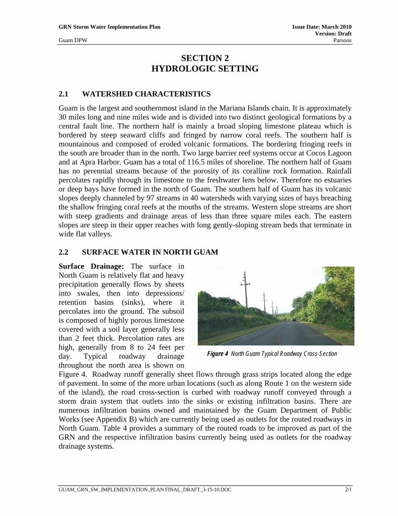
Surface Drainage: The surface in North Guam is relatively flat and heavy precipitation generally flows by sheets into swales, then into depressions/ retention basins (sinks), where it percolates into the ground. The subsoil is composed of highly porous limestone covered with a soil layer generally less than 2 feet thick. Percolation rates are high, generally from 8 to 24 feet per day. Typical roadway drainage throughout the north area is shown on Figure 4. Roadway runoff generally sheet flows through grass strips located along the edge of pavement. In some of the more urban locations (such as along Route 1 on the western side of the island), the road cross-section is curbed with roadway runoff conveyed through a storm drain system that outlets into the sinks or existing infiltration basins. There are numerous infiltration basins owned and maintained by the Guam Department of Public Works (see Appendix B) which are currently being used as outlets for the routed roadways in North Guam. Table 4 provides a summary of the routed roads to be improved as part of the GRN and the respective infiltration basins currently being used as outlets for the roadway drainage systems.
Figure 4 North Guam Typical Roadway Cross-Section

GRN Storm Water Implementation Plan Issue Date: March 2010 Version: Draft Guam DPW Parsons
GUAM_GRN_SW_IMPLEMENTATION_PLAN FINAL_DRAFT_3-15-10.DOC 2-2
Table 4 – Summary of Infiltration Basins along GRN (North Guam)
Flood Zones: The Federal Emergency Management Agency (FEMA) has mapped flood hazard areas throughout the island for the National Flood Insurance Program (NFIP) and has designated the areas on Flood Insurance Rate Maps (FIRMs). These maps are provided in Appendix D. As shown in FIRM Map 6600010125D, various depressions are located throughout the area and have been designated as Flood Hazard Zone X (areas of less than 1 ft depth or areas with less than 1 sq mile of contributing drainage area). The largest depression within the north area is referred to as the Harmon Sink. This sink has been mapped as a Flood Hazard Zone AE by FEMA and crosses under Route 1 with a high water elevation of 93 feet above mean sea level. In general, the sink acts as an outlet for much of the local storm water runoff in the area including street drainage (see
Route Location 1 Tamuning – S-20 Harmon Park Subdivision
1, 3 Dededo – Rte 1 Near M. Mall Northgate/ Rte 3 1 Dededo – Between Route 27a and Kayan R. Agustin 1 Dededo – Route 1 at Santa Barbara 1 Dededo – Route 1 at Calamendo
1, 28 Dededo – Route 1 at Cr. Y-Sengsong Rd. 1 Yigo – Mapola Loop. Ghura 505 1 Yigo - Milalak Dr. at St. Pacific Memorial Park 1 Yigo – Abanbang Loop @ Q Ponderosa Acres 1 Yigo – SS-29 Nissho Subdivision
1, Chalan Lujana Yigo – Baki Court @ Perez Acres
3 Dededo – Kamute Lane, Astumbo
3, 28 Dededo – Chalan Sibukao, Astumbo
3 Dededo – Mabolo Lane @ Fern Terrace
3, 9 Dededo – Snowball St. - Santa Ana Sub 3, 9 Dededo – Ch Santa Maria - Santa Ana Sub 16 Dededo - Route 16 Near Iglesia Ni Kristo Church
16, 27 Mangilao – Hegao Loop, Harmon Gardens (E of Route 16) 26 Mangilao – Gardenia and Rte 26 – Latte Heights 26 Mangilao – Daisy Lane and Rte 26 – Latte Heights 26 Mangilao – Mil. Flores and Rte 26 - Latte Heights 26 Dededo – Magof Dr & SS-17 (East of 26)
26, 25 Dededo – Ch Gafo, PGD Subd. (E of Rte 26) 27 Dededo - Route 27 at Kayen Cascado
28 Dededo - Route 27a at Rte 28
Figure 5 Harmon Sink at Rte 1
GRN Storm Water Implementation Plan Issue Date: March 2010 Version: Draft Guam DPW Parsons
GUAM_GRN_SW_IMPLEMENTATION_PLAN FINAL_DRAFT_3-15-10.DOC 2-3
Figure 5 where the sink is located adjacent to Route 1). South of Route 3, the drainage along Route 1 is conveyed to the Harmon Sink via a storm drain network.
2.3 SURFACE WATER IN SOUTH GUAM
Surface Drainage: Unlike northern Guam’s relatively flat limestone plateau, surface drainage in the Southern Guam Watershed is accommodated by the numerous rivers that dissect the mountainous uplands in this watershed area. Volcanic rock forms the foundation of the island and is exposed over about 35 percent of the island’s surface, predominantly in southern Guam. This portion of the island is vegetated with a mix of grassland and patchy forest. Also located in this area is the Apra Harbor which is a large Barrier Reef System. Apra Harbor covers over three square miles, with the Navy’s Inner Apra Harbor encompassing approximately 650 acres. For south Guam, surface drainage from the roadway in the rural areas generally sheet flows through grass strips located along the edge of pavement. In the more urban locations, the road cross-section is curbed with roadway runoff conveyed through storm drain systems. Several infiltration basins are located along Route 10 in the southern area (see Appendix B) and are used as outlets for the drainage systems.
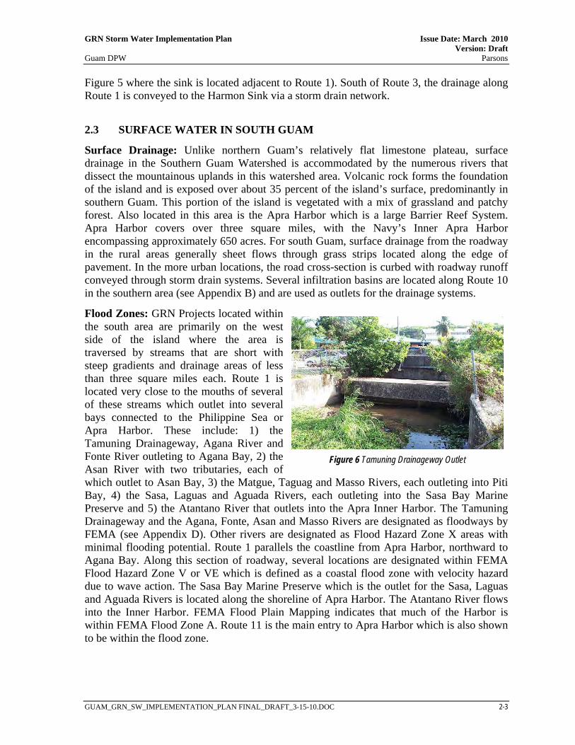
Flood Zones: GRN Projects located within the south area are primarily on the west side of the island where the area is traversed by streams that are short with steep gradients and drainage areas of less than three square miles each. Route 1 is located very close to the mouths of several of these streams which outlet into several bays connected to the Philippine Sea or Apra Harbor. These include: 1) the Tamuning Drainageway, Agana River and Fonte River outleting to Agana Bay, 2) the Asan River with two tributaries, each of which outlet to Asan Bay, 3) the Matgue, Taguag and Masso Rivers, each outleting into Piti Bay, 4) the Sasa, Laguas and Aguada Rivers, each outleting into the Sasa Bay Marine Preserve and 5) the Atantano River that outlets into the Apra Inner Harbor. The Tamuning Drainageway and the Agana, Fonte, Asan and Masso Rivers are designated as floodways by FEMA (see Appendix D). Other rivers are designated as Flood Hazard Zone X areas with minimal flooding potential. Route 1 parallels the coastline from Apra Harbor, northward to Agana Bay. Along this section of roadway, several locations are designated within FEMA Flood Hazard Zone V or VE which is defined as a coastal flood zone with velocity hazard due to wave action. The Sasa Bay Marine Preserve which is the outlet for the Sasa, Laguas and Aguada Rivers is located along the shoreline of Apra Harbor. The Atantano River flows into the Inner Harbor. FEMA Flood Plain Mapping indicates that much of the Harbor is within FEMA Flood Zone A. Route 11 is the main entry to Apra Harbor which is also shown to be within the flood zone.
Figure 6 Tamuning Drainageway Outlet

This page intentionally left blank
GRN Storm Water Implementation Plan Issue Date: March 2010 Version: Draft Guam DPW Parsons
GUAM_GRN_SW_IMPLEMENTATION_PLAN FINAL_DRAFT_3-15-10.DOC 3-1
SECTION 3 STORM WATER REGULATORY MANDATES, COORDINATION
AND IMPLEMENTATION
This section provides a summary of the regulatory context for the GRN projects, the regulatory agency coordination process as well as required permits and clearances.
3.1 STORM WATER REGULATIONS
Executive Order 11988 (Floodplain Management) directs all federal agencies to refrain from conducting, supporting, or allowing actions in floodplains unless it is the only practicable alternative. A Floodplain Evaluation is required under the National Flood Insurance Program (23 CFR 650, Subpart A Section 650). Section 650.111 of the regulation calls for location hydraulic studies to be performed to avoid and/or minimize hydrologic and floodplain impacts.
Coastal Zone Management Act (16 CFR 1451 et seq.) The Coastal Management Act establishes a federal-state partnership to provide for the comprehensive management of coastal resources. The Bureau of Statistics and Plans (BSP) is the agency responsible for enforcing this law and has developed the Guam Coastal Management Program (GCMP). The GCMP is a Territorial policy to guide the use, protection and development of land and ocean resources within Guam’s coastal zone. In accordance with the Coastal Zone Management Act of 1972 (P.L. 92-583), as amended (P.L. 94-370), the Bureau of Planning (BOP), as the lead agency of the GCMP, is responsible for conducting federal consistency review.
Federal Clean Water Act. The primary federal law governing water quality is the Clean Water Act (CWA) of 1972. This Act provides for the restoration and maintenance of the chemical, physical, and biological integrity of the Nation's waters. Three sections of the CWA, in particular, are the focus of construction-phase compliance.
• Section 401, water quality certification, regulates impacts of the placement of dredged or fill material on water quality. All federal permits for work in marine waters, rivers, streams and wetlands require Section 401 water quality certification from Guam EPA (GEPA).
• Section 402, the National Pollutant Discharge Elimination System (NPDES) permit program controls water pollution by regulating point sources that discharge pollutants into waters of the U.S. Projects that disturb greater than one acre of soil are required to file a Notice of Intent with US EPA, develop a construction site Storm Water Pollution Prevention Plan and file a Notice of Termination upon project stabilization.
GRN Storm Water Implementation Plan Issue Date: March 2010 Version: Draft Guam DPW Parsons
GUAM_GRN_SW_IMPLEMENTATION_PLAN FINAL_DRAFT_3-15-10.DOC 3-2
• Under Section 404 of the CWA, the U.S. Army Corps of Engineers (ACOE) authorizes discharges of dredged or fill material into waters of the U.S. through a permit program.
Guam Soil Erosion and Sedimentation Control Regulations. In 1975, the Guam EPA first developed the Guam Soil Erosion and Sedimentation Control Regulations under the authority of 10 Guam Code Annotated (GCA), Chapter 47. These were then updated and revised in 1985 and again in 1997. The regulations address important provisions that: 1) control nonpoint source pollution from runoff within Guam’s waters such as runoff containing fertilizers, pesticides and other polluting substances carried by sediment, 2) protect property and 3) promote public health, safety and welfare by regulating grading, clearing, grubbing and stockpiling and by setting specific requirements for erosion and sedimentation control within the island of Guam.
Draft Guam Erosion Control and Stormwater Management Regulations. GEPA has prepared a draft regulation for erosion control and stormwater management which updates the existing regulations described above. The regulations set limits for erosion, sedimentation and nonpoint source runoff and establish administrative procedures for the issuance of clearing, grading and stockpiling permits. Requirements for grading plans, cut and fill slopes, Soil Reports, Erosion and Sediment Control Plans, Storm Water Pollution Prevention Plans (SWPPPs) and post-construction storm water management are provided. The requirements are consistent with those set forth in the 2006 Storm Water Manual.
US EPA Sole Source Aquifer Program. The Sole Source Aquifer (SSA) Program is authorized by Section 1424(e) of the Safe Drinking Water Act (SDWA) of 1974. Since 1977, it has been used by communities to help prevent contamination of groundwater from federally-funded projects. Designation of an aquifer as a sole source aquifer provides US EPA with the authority to review federal financially assisted projects planned for the area to determine their potential for contaminating the aquifer. All projects proposed over the North Guam Lens groundwater aquifer (NGL) are subject to review by GEPA as well as by the US EPA. Projects are scrutinized for potential direct or indirect impacts to groundwater.
Underground Injection Control: GEPA’s Underground Injection Control (UIC) program (22 Guam Administrative Rules Division II Chapter 9) includes underground injection wells and underground injection systems for use as drainage systems for storm water runoff. These permits are issued only after all other methods of storm water disposal have been thoroughly investigated and exhausted. This disposal method requires a higher burden of justification and typically is issued with very strict pretreatment and/or monitoring requirements for the life of the injection well.
3.2 REGULATORY AGENCY COORDINATION PROCESS
Implementation of any GRN project will require coordination with local and federal agencies prior to project advertisement (i.e. the design phase) and prior to construction (i.e. build phase).
GRN Storm Water Implementation Plan Issue Date: March 2010 Version: Draft Guam DPW Parsons
GUAM_GRN_SW_IMPLEMENTATION_PLAN FINAL_DRAFT_3-15-10.DOC 3-3
3.2.1 PROJECT PHASES
The design approval process should be initiated at the beginning of the design phase of any project. The approval process should include a scoping meeting with agencies that would be considered stakeholders to the particular project. Such agencies include Guam DPW, GEPA, US EPA Region 9, BSP, and ACOE (if needed for 404 permitting requirements). With respect to overall stormwater management, plans shall be submitted and coordination meetings will be arranged during the design process with various agencies.
Both federal and local agencies require permits and clearances for activities that have or may potentially have an impact on Guam’s ground or surface water. Table 5 displays agency-specific permits and clearances that are required prior to construction as a part of the build phase of any GRN project. A brief description regarding submittal and timing of each permit or clearance is also discussed.
Sole Source Aquifer Protection Review/Clearance: The GRN is within the boundaries of the NGL which has been designated as a Sole Source Aquifer by US EPA Region 9. Design reviews for consistency with the Sole Source Aquifer Program will be subject to an Aquifer Protection Review by GEPA as well as review by US EPA Region 9 for all projects. GEPA will forward the design plans provided during design to US EPA Region 9 for this effort. To comply with the US EPA Sole Source Aquifer Program and to prevent potential contamination from roadway runoff, runoff will be pre-treated (through devices such as bio-strips, bio-swales or retrofitted catch basins) and/or routed to infiltration facilities that are a minimum separation distance of 1000-ft from any water supply wells which provide a direct conduit into the drinking water aquifer. Existing production wells are shown as green points in Figures 2 and 3.
Coastal Management Program Consistency Review: The GRN is within the boundaries of the Coastal Zone Management Area. All GRN projects will require a federal consistency review which will be processed as federal assistance to local governments, thus normally conducted through procedures established by Guam pursuant to Executive Order 12372 – intergovernmental review of federal programs, or through State clearinghouse procedures. P.L. 26-169. The DPW, during the design phase, will submit an application for concurrence in a consistency determination to the Bureau of Planning (BOP). The BOP then routes the information to a number of individual agencies for their review, including Guam EPA.

GRN Storm Water Implementation Plan Issue Date: March 2010 Version: Draft Guam DPW Parsons
GUAM_GRN_SW_IMPLEMENTATION_PLAN FINAL_DRAFT_3-15-10.DOC 3-4
Table 5 - Agency Required Permits and Clearances
Local/ Federal
Agency Permit or Clearance Implementation Design1 Construction2
Local
Guam Department of Public Works
Building Permit X Clearing and Grading Permit X
Guam EPA
Erosion Control Permit X Underground Injection Control Permit X
Aquifer Protection Review X Section 401 Water Quality Certification X
Storm Water Runoff Drainage System Plan X Storm Water Pollution Prevention Plan
(SWPPP) X
Bureau of Statistics and Plans Coastal Zone Management Act X
Federal US EPA, Region 9
Sole Source Aquifer Protection X Section 402 National Pollutant Discharge and Elimination System (NPDES) Permit / Storm Water Pollution Prevention Plan (SWPPP)
X
US Army Corps of Engineers
Section 404 Discharge of Dredged or Fill Material into Waters of the United States X
1) Design phase, prior to advertisement for construction bids. 2) Construction phase, prior to Notice to Proceed. Building Permit: The DPW, through the One-Stop Permit Center is responsible for issuing Building Permits. The review process involves routing the Construction Contract and the Plans and Specifications to a number of individual agencies, including GEPA, to ensure compliance with applicable law, regulatory standards, procedures, policies and rules within their respective mandated area of concern.
Clearing and Grading Permit and Erosion Control Permit: The DPW, through the One-Stop Permit Center is responsible for issuing a Clearing and Grading Permit (CGP). Clearance from several different Government of Guam agencies and departments are required, including GEPA. GEPA is responsible for issuing an Erosion Control Permit thus GEPA assumes the lead review and approval responsibility to ensure the Construction Contracts (plans and specifications) are in compliance with the Guam Soil and Sedimentation Regulations. In order to receive an Erosion Control Permit, an Environmental Protection Plan (EPP) which includes an Erosion Control Plan (ECP) to protect water quality of the closest body of water, fresh or marine (from Guam EPA Environmental Guidebook) must be submitted with the CGP application. Therefore, it is recommended that the Erosion Control Plan be submitted to GEPA during the design process.
Underground Injection Control (UIC) Permit: This control permit is utilized to ensure that pollutants are not migrating into the groundwater through the UIC wells or systems. Operating permits may be issued in approximately 60 days for existing wells or in approximately 90 days for new wells, depending on the complexity of the injection proposal.
GRN Storm Water Implementation Plan Issue Date: March 2010 Version: Draft Guam DPW Parsons
GUAM_GRN_SW_IMPLEMENTATION_PLAN FINAL_DRAFT_3-15-10.DOC 3-5
Operating permits are renewable every two years (from 10 GCA Chapter 46 Water Resources Conservation Act, Section 46105 and Guam EPA Environmental Guidebook).
Section 401 Water Quality Certification: All federal permits for work in marine waters, rivers, streams or wetlands require GEPA Section 401 Water Quality Certification. Section 401 Water Quality Certification issuance identifies that construction or operation of a proposed project or facility will be conducted in a manner consistent with Guam Water Quality Standards. Submission of a completed 401 Water Quality Certification form is required. GEPA may also require submittal of the following additional plans and documentation prior to Section 401 issuance or as a condition of issuance:
• Construction Drawing Plans • Wetland Delineation Map • Specifications • Environmental Baseline Survey (marine, freshwater aquatic or adjacent upland) • Environmental Protection Plan • Water Quality Monitoring Plan • Environmental Impact Assessment/Statement (EIA/EIS) • Mitigation/Restoration Plans
Storm Water Runoff Drainage System Plan: The Guam Soil and Sedimentation regulations also require a Storm Water Runoff Drainage System Plan when the area to be graded is more than 5,000 square feet or a proposed cut or fill is greater than five feet in height. Note that the GRN Storm Water Implementation Plan was developed as an overall Storm Water Runoff Drainage System Plan for the Guam Road Network projects. The designers will be required to show how their designs comply with the recommendations set forth in this document by submitting plans to the Guam DPW and GEPA during the design process. Section 402 National Pollutant Discharge and Elimination System 2008 General Permit for Stormwater Discharges from Construction Activities (NPDES Permit No. GUR100000): The US EPA Construction General Permit is a NPDES permit issued under the authority of the CWA and associated regulations. Permit coverage for stormwater discharges from construction activity occurring within Guam is provided by a legally separate and distinctly numbered permit (NPDES Permit No. GUR100000). This permit regulates the discharge of storm water from construction sites that disturb 1 acre or more of land, and from smaller sites that are part of a larger, common plan of development. This permit requires operators of construction sites to implement storm water controls and to develop storm water pollution prevention plans (SWPPPs) to prevent sediment and other pollutants associated with construction sites from being discharged in storm water runoff. The following water pollution control devices to be used during construction will be identified as part of the SWPPP:
• Source identification and control (through covering and containing) of potential pollutants
GRN Storm Water Implementation Plan Issue Date: March 2010 Version: Draft Guam DPW Parsons
GUAM_GRN_SW_IMPLEMENTATION_PLAN FINAL_DRAFT_3-15-10.DOC 3-6
• Erosion control techniques for temporary, permanent and wind conditions (types of erosion control to be considered include rolled erosion control products and hydraulically applied mulches)
• Sediment control techniques with the specific objective of maintaining sediment loads consistent with pre-construction levels (types of sediment control BMPs to be considered include fiber rolls, silt fence, drainage inlet protection and sediment traps and basins)
• Control of non-stormwater through elimination of sources
In addition, specific BMPs for construction work upstream, adjacent and within waterways will be identified and will include such items as:
• Minimizing demolition and construction activities over streams during the wet season • Use of non-shattering demolition methods that would normally scatter debris • Securing all materials adjacent to streams to prevent discharges into receiving waters
via wind • Using attachments on equipment to catch debris from small demolition operations • Stockpiling accumulated debris and waste generated from demolition away from
streams • Isolating work areas within streams from flow using sheet piling, k-rails, or other
methods of isolation • Using drip pans during equipment operation, maintenance, cleaning, fueling, and
storage for spill prevention • Keeping equipment used in streams leak-free • Directing water from concrete curing and finishing operations away from inlets and
water courses to collection areas for dewatering
The SWPPP also includes a stormwater runoff sampling and analysis plan to ensure that BMPs are functioning effectively during construction. The SWPPP must be prepared (generally by the Contractor) and must be available for review by US EPA, Region 9 and/or GEPA prior to construction.
An operator is authorized to discharge stormwater from construction activities under the terms and conditions of the Construction General Permit seven (7) calendar days after acknowledgment of receipt of a completed Notice of Intent (NOI) filed with US EPA3. The exception to this 7-day timeframe is if US EPA delays authorization based on eligibility considerations such as:
• Request to review SWPPP • Endangered species documentation • Consultation with US Fish and Wildlife Service • Request to revise SWPPP • Request to file for an individual permit
3 For GRN projects both DPW and the Contractor need to submit a NOI using US EPA’s online system (i.e., eNOI).

GRN Storm Water Implementation Plan Issue Date: March 2010 Version: Draft Guam DPW Parsons
GUAM_GRN_SW_IMPLEMENTATION_PLAN FINAL_DRAFT_3-15-10.DOC 3-7
Thirty (30) days after cessation of construction activities and final stabilization of the site has been established, a Notice of Termination (NOT) must also be filed with US EPA Region 9. Authorization to discharge terminates at midnight of the day the NOT is signed.
Section 404 Dredge/Fill Permitting: This permit regulates the discharge of dredged or fill material into waters of the US. The program’s scope also includes the regulation of discharges of dredged or fill material into wetlands adjacent to national waters. Although this permit program is administered by the Secretary of the Army through the ACOE, Sections 401 and 404 are related and result in coordinated permitting with GEPA and ACOE. The ACOE will not issue a 404 permit without satisfaction of Section 401 requirements.

This page intentionally left blank

GRN Storm Water Implementation Plan Issue Date: March 2010 Version: Draft Guam DPW Parsons
GUAM_GRN_SW_IMPLEMENTATION_PLAN FINAL_DRAFT_3-15-10.DOC 4-1
SECTION 4 WATER POLLUTION CONTROL STRATEGY
4.1 CONSTRUCTION
Construction site best management practices (BMPs) are to be used during construction to minimize the impacts of construction and construction-related activities on the watershed. They include, but are not limited to, temporary soil stabilization, temporary sediment control, waste management, material pollution controls and other non-storm water BMPs. Temporary soil stabilization and sediment controls provide the first line of defense in preventing off-site sedimentation and are designed to remove sediment from runoff before the runoff is discharged from the site. These control measures can be further divided into two major classes of controls: stabilization practices and structural practices. Typically, a combination of both (as well as non-stormwater management and waste management and material pollution controls) is necessary throughout the site to provide adequate water quality protection. A more thorough description of these practices is given in the “Draft Transportation Storm Water Drainage Manual” (TSDM), Parsons 2010.
In the event groundwater dewatering is proposed or anticipated during construction, and an alternative method of disposal (e.g., discharge to sanitary sewer, retention on site) is not feasible, then the Contractor would coordinate with the DPW and GEPA prior to discharging waste. A Stormwater Pollution Prevention Plan (SWPPP) will be prepared by the Contractor after final design documents are available. This is required for compliance with the NPDES Construction General Permit and is regulated by US EPA, Region 9. The selection of construction BMPs will be determined as part of the development for the SWPPP.
4.2 POST-CONSTRUCTION
The post-construction stormwater program was developed based on guidelines set forth in the 2006 Manual and the TSDM. BMPs for controlling post-construction pollution are broken down into:
• Source Control – BMPs used to prevent contaminants from entering the runoff stream at the source of pollution (e.g. along unlined ditches or non-vegetated side slopes that could contribute sediment to the runoff stream), and
• Treatment Control – BMPs used to treat the runoff by removing the contaminants that have already entered the runoff stream (e.g. removal of sediment through filtration, infiltration or detention).
4.2.1 SOURCE CONTROL The overall surface water quality program was designed to incorporate pollution prevention mechanisms through the use of source control BMPs. These include the following items to be incorporated into the design documents:
• Minimize impervious surfaces • Stabilize disturbed soil areas and existing erodible surfaces • Maximize vegetated surfaces

GRN Storm Water Implementation Plan Issue Date: March 2010 Version: Draft Guam DPW Parsons
GUAM_GRN_SW_IMPLEMENTATION_PLAN FINAL_DRAFT_3-15-10.DOC 4-2
• Preserve existing vegetation • Construct concentrated flow conveyance systems • Provide outlet protection (energy dissipation)
4.2.2 TREATMENT CONTROL Pollutant removal will be accomplished using treatment BMPs which are measures designed to remove pollutants from stormwater runoff prior to discharging (directly or indirectly) to receiving waters. GEPA requires that permanent treatment BMPs are considered for all new construction and major reconstruction projects that do not have exemption status (GEPA 2010)4.
4.2.2.1 POLLUTANTS OF CONCERN Recent discharge characterization studies have shown that pollutants of concern generated from roadways within an environment similar to what is found in Guam (with land use designated as open space, residential or commercial) include suspended solids and metals (the latter generally found in particulate form). Trash and debris are also considered pollutants of concern within urban areas. Hydrocarbons are of concern mainly at locations where vehicles idle for extended periods of time such as toll stations, or at fueling areas and vehicle maintenance facilities. None of these types of facilities (referred to as “Hot Spots” in the 2006 Manual) are included in the Guam Road Network.
4.2.2.2 TREATMENT BMP SELECTION Treatment BMPs are selected for projects based on those best suited for: 1) the pollutants of concern (namely suspended solids, particulate metals and trash), 2) for the hydrologic, geologic and physical roadway characteristics on Guam, and 3) those considered easy to maintain to ensure proper operation once the network is completed.
These treatment BMPs generally include infiltration devices, biofiltration swales, biofiltration strips, media filters, detention devices and gross solids removal devices. Where necessary, recharge augmentation BMPs (infiltration basins, underground infiltration galleries, dry wells and if designed properly, vegetated swales and strips), should be considered where new impervious surfaces would diminish the overall recharge to the groundwater basins (specifically to the US EPA designated sole source aquifer in North Guam). Note that where flows are already directed to existing depressions and infiltration basins, additional recharge augmentation is considered unnecessary since runoff would be retained within the basins and subsequently be allowed to infiltrate into the groundwater regime.
4.2.3 TREATMENT BMP DESIGN BMP design depends on the amount of runoff expected, which is affected by:
• Location, • Land use,
4 Guam Environmental Protection Agency. 2010. Guam Erosion Control and Stormwater Management Draft Regulations, Section 10101 D. January 2010.

GRN Storm Water Implementation Plan Issue Date: March 2010 Version: Draft Guam DPW Parsons
GUAM_GRN_SW_IMPLEMENTATION_PLAN FINAL_DRAFT_3-15-10.DOC 4-3
• Drainage area, • Storm intensity, • Topography, • Soil characteristics, • Quantity of impervious area, • Constituents of concern to be removed, • Storm volume, and • Peak flow conditions.
The Water Quality Design Storm is the particular event that generates runoff rates or volumes that the drainage facilities are designed to handle. Treatment BMPs are designed to treat the flow of smaller, more frequent storm events. The volume of flows associated with these more frequent events are commonly referred to as the water quality volume or WQV (as defined in the 2006 Manual and the TSDM) for BMP designs based on volume, and the water quality flow (WQF) for BMP designs based on flow.
BMP Design Guidelines for Infiltration Devices, Detention Devices, and Media Filters can be found in the 2006 Manual and the TSDM after its finalization. Design guidelines for biofiltration swales and strips are included in Appendix E. The parameter used for these designs is described as the water quality flow rather than the water quality volume as described below.
Water Quality Volume: The water quality volume (WQV) corresponds to the active storage capacity for stormwater treatment BMPs and is required for sizing volume-based BMP treatment systems such as infiltration basins, infiltration trenches, media filters or detention basins. The WQV for treatment BMPs is intended to provide the level of protection specified in the 2006 Manual for the Water Quality Classification indicated in Figure 12. As shown on this figure, the GRN projects are all within areas with a moderate water quality classification. As per the 2006 Manual and the TSDM, areas with this type of classification should have associated treatment BMPs that treat runoff from the 80th percentile storm which corresponds to a storm event producing 0.8 inches of precipitation. The WQV is estimated as a depth of 0.8 inches times the individual tributary areas and the percent imperviousness.
Water Quality Flow: The water quality flow (WQF) corresponds to the design flow used for flow-based stormwater treatment BMPs that are usually filtration type BMPs such as grass swales and buffer strips. For the project area, the WQF is calculated using the Rational Method and a precipitation intensity of 0.3 inches/hour. This rate corresponds to the 1 year – 1 hour rainfall event on Guam which is slightly above the 80th/90th percentile storm events used for the water quality volume calculations (see Figure 9). This rainfall intensity is consistent with precipitation intensities Figure 9: Historic Hourly Rainfall Depths
0.3 Depth (inches per 1 hr) Source: Draft TSDM
Ret
urn
Perio
d(Y
ears
)
1
5
0 1 2
GRN Storm Water Implementation Plan Issue Date: March 2010 Version: Draft Guam DPW Parsons
GUAM_GRN_SW_IMPLEMENTATION_PLAN FINAL_DRAFT_3-15-10.DOC 4-4
used for flow-based storm water treatment BMPs located in Coastal Northern California (ranging from 0.27 to 0.36 inches per hour). In contrast, for the drier climate of Southern California, the water quality flow (based on an 85th percentile storm) is calculated using rainfall intensities on the order of 0.16 to 0.20 inches per hour. A flow rate based on a rainfall intensity of 0.3 inches per hour was therefore considered appropriate for flow-based treatment BMP design on the island of Guam.
4.3 TYPES OF TREATMENT BEST MANAGEMENT PRACTICES
Biofiltration Swales/Strips: Biofiltration swales (bioswales) are vegetated channels that receive directed flow and convey stormwater. Biofiltration strips (biostrips) are vegetated sections of land over which stormwater flows as overland sheet flow. Pollutants are removed by straining through the grass, sedimentation, adsorption to soil particles, and infiltration into the soil. Biostrips and bioswales are mainly effective at removing debris, solid particles (suspended solids) and associated pollutants absorbed to these solids and particulate metals. These BMPs are most applicable in areas where site conditions and climate allow for the establishment of vegetation (very good on the island of Guam), where flow velocities are low, and where the length of flow through the bioswales or across the biostrips can be maximized. In accordance with the Caltrans Treatment BMP Technology Report, April 2007, bioswales have good removal efficiencies for the pollutants of concern, namely metals and total suspended solids. When designed appropriately, these BMPs have been found to remove over 80% of these pollutants.
Bioswales should be considered at locations along the alignments where longitudinal slopes are consistent with design criteria and where right-of-way is available (generally within the less urbanized areas). A key consideration in the design of bioswales is to have peak flow velocities (for higher storm event flows) of less than 4 feet/second through the channel to avoid erosion and water quality flow velocities low enough to maintain a hydraulic residence time greater than 5 minutes within the swale (at a maximum depth of 0.5 feet). Generally, this requires slopes to be less than 3.0 percent.
Biostrips are sloped vegetated land areas located adjacent to impervious areas, over which storm water runoff flows as sheet flow. Pollutants are removed by filtration through the vegetation, uptake by plant biomass, sedimentation, adsorption to soil particles, and infiltration through the soil. Biostrips are effective at trapping litter, Total Suspended Solids (soil particles), and particulate metals (Caltrans, 2008). The slope of the biostrip should be designed as flat as possible (1:4 or flatter). The minimum recommended slope length for Biostrips is 15 ft for any side slope ratio as long as the site supports a minimum 70 percent vegetation coverage without rills or gullies. Biostrips can be used in lieu of shoulders in rural areas (referred to as grass shoulders). Infiltration Devices: An infiltration basin is a device designed to remove pollutants from surface discharges by capturing stormwater runoff and infiltrating it directly into the soil rather than discharging to receiving waters. The feasibility criteria for infiltration basins require: 1) sufficient area to accommodate a basin with side slopes of 3:1, maintenance access, and fencing at the top of embankment, 2) sufficient soil infiltration and permeability

GRN Storm Water Implementation Plan Issue Date: March 2010 Version: Draft Guam DPW Parsons
GUAM_GRN_SW_IMPLEMENTATION_PLAN FINAL_DRAFT_3-15-10.DOC 4-5
rates, 3) sufficiently low water table, and 3) no threat to local groundwater quality5. Infiltration basins are a good choice for surface water protection where soils exist that support their use. Detention Devices: A detention basin is a permanent device that temporarily detains stormwater runoff under quiescent conditions such that sediment and particulates are able to settle before the runoff is discharged. A portion of the detained water is also lost due to infiltration and evaporation. Detention basins remove litter, settleable solids (debris), TSS (total suspended solids), and pollutants that are attached (adsorbed) to the settled particulate matter. Detention basins are primarily suited for sites where: 1) the seasonal high groundwater is below the bottom of the basin, and 2) where sufficient head is available so that water stored in the basin does not cause objectionable backwater conditions in the storm drain systems. In accordance with the Caltrans Treatment BMP Technology Report, April 2007, detention basins have good removal efficiencies for pollutants of concern – total metals (mainly those in particulate form) and suspended solids. The detention basins are generally equipped with outlets that meter out the flow at a low rate and are mainly considered as a suitable BMP for flow control where existing flows are being increased due to increased impervious area.
Media Filters: Media filters primarily remove particulates from runoff by sedimentation and filtration (through a porous media such as a sand bed generally equipped with a drainage system under the media) and are also effective at removing dissolved metals and litter. The filters can be designed at grade, with an open top, or designed below grade within a closed chamber. At grade filters may be configured with earthen sides or concrete while below grade filters are designed as concrete chambers. Runoff is initially routed through a sediment chamber which allows settleable solids to settle out prior to filtering the runoff through the bed of media. The filters require sufficient hydraulic head to operate by gravity (a minimum of 3 feet). Closed chamber media filters are suitable for relatively small drainage areas and are usually only recommended where surface use over the filter is required. At grade earthen media filters require a fairly large footprint, though are the least expensive alternative. Maintenance is usually easier for at-grade filters since the facility is not considered a confined space. However, the filter beds are more susceptible to vegetative growth which may require more frequent maintenance activities than underground filters.
5 According to 22 GAR 002-7, Section 7130(b) Wellhead Protection Area shall mean the surface and subsurface area surrounding a water well or wellfield supplying a public water system through which contaminants are reasonably likely to move toward and reach such water well or wellfield, or a minimum of 1,000 feet radius of any potable water supply well. Thus wellhead protection applies to UIC wells as well as infiltration basins.

GRN Storm Water Implementation Plan Issue Date: March 2010 Version: Draft Guam DPW Parsons
GUAM_GRN_SW_IMPLEMENTATION_PLAN FINAL_DRAFT_3-15-10.DOC 4-6
Catch Basin Retrofits: Within urban areas where the on-site roadway drainage systems include catch basins connected to conveyance pipelines, there are often no areas available for downstream treatment BMPs. In these areas, it is recommended that the catch basins be retrofitted to accommodate removal of litter and debris (commonly referred to as gross solids). The retrofit can be accomplished in various ways. A simple retrofit option of catch basins is to ensure that all catch basins have a hooded outlet to prevent floatable materials, such as trash and debris, from entering the storm drain system. An opening filled with pervious material placed in the bottom of the catch basin will enable a small amount of runoff to infiltrate, preventing standing water in the bottom of the structure (see Figure 10). A second option is to incorporate a reverse 90 degree bend in the outlet structure. The outlet can also be equipped with a filtering plate such as a plastic or metal wire mesh with 0.5 mm openings in order to filter out some of the larger suspended solids.
Flow Splitters: The purpose of the flow splitter is to direct water quality flows (WQF) to the BMPs for stormwater treatment, while allowing peak flows to remain in their original watershed/discharge location (mimicking pre-project conditions). The splitter design shown in Figure 11 represents a typical vaulted flow splitter. Alternative designs may be evaluated in the final design phase for projects requiring these devices.
Other BMP Options: There are many other BMP options available for both water pollution control and recharge augmentation such as dry wells, underground infiltration galleries, infiltration trenches, wetlands, and others. The BMPs provided in this report are those which are most likely to be used throughout the GRN Network, though other BMPs may be prudent for use at certain site specific areas. Descriptions and design criteria for these BMPs are provided in the 2006 Manual and the TSDM.
Permeable Material
Figure 10: Sample Catch Basin Retrofit

GRN Storm Water Implementation Plan Issue Date: March 2010 Version: Draft Guam DPW Parsons
GUAM_GRN_SW_IMPLEMENTATION_PLAN FINAL_DRAFT_3-15-10.DOC 4-7
Figure 11: Sample Flow Splitter Design

This page intentionally left blank

GRN Storm Water Implementation Plan Issue Date: March 2010 Version: Draft Guam DPW Parsons
GUAM_GRN_SW_IMPLEMENTATION_PLAN FINAL_DRAFT_3-15-10.DOC 5-1
SECTION 5 POLLUTION SOURCE CONTROL
Source control BMPs are practices used to prevent contaminants from entering the runoff stream at the source of pollution. These include such practices as lining unlined ditches or vegetating side slopes that could contribute sediment to the runoff stream or preventing increases in offsite flow velocities that could result in downstream erosion. This section describes typical post-construction source control BMPs that can be used for the GRN projects.
5.1 REDUCTION OF IMPACTS FROM FLOW CHANGES
North Guam: As mentioned previously, the north area of Guam has no perennial streams because of the porosity of its coralline rock formation. Rainfall percolates rapidly through its limestone to the freshwater lens below. The surface in this area is relatively flat, and heavy precipitation generally flows by sheets into swales, then into depressions/ retention basins, where it percolates into the ground. Planned roadway improvements in North Guam are generally pavement strengthening projects that will create no increase in impervious surfaces. Where possible, the pavement strengthening projects will include biostrips and/or swales which will generally decrease existing flow rates prior to flow conveyance to existing infiltration basins and surface depressions. Existing conveyance facilities and outlets may be adequate to accommodate the future widening. The facilities must be evaluated for the roadway design storm events specified in the TSDM.
South Guam: With the exception of a few intersections, increases in impervious surfaces are not anticipated in South Guam and drainage flow patterns are to remain unchanged. Bioswales/ strips will also be used wherever possible in South Guam to both treat and potentially reduce existing flow rates entering the various surface waters (including streams, surface depressions/ infiltration basins and bays/estuaries).
5.2 PRESERVATION OF EXISTING VEGETATION
Existing desirable vegetation and landscaping will be protected in place, where possible, and will be shown on the plans. The plans should include demarcation of the limit of disturbed soil area to ensure that adjacent vegetation is preserved during construction to the extent possible..
5.3 CONCENTRATED FLOW CONVEYANCE SYSTEMS
Risks due to erosion or washout may be minimized through the use of rock slope protection, hydroseeding, ground cover, mulch, longitudinal ditches, and down drains. Velocity dissipation devices, flared end outlets, headwalls, transition structures, and splash walls may be incorporated into the design, where necessary, at culvert inlets and outlets to prevent erosion. Grass or concrete lined longitudinal ditches may be incorporated to intercept sheet

GRN Storm Water Implementation Plan Issue Date: March 2010 Version: Draft Guam DPW Parsons
GUAM_GRN_SW_IMPLEMENTATION_PLAN FINAL_DRAFT_3-15-10.DOC 5-2
flow, where necessary, and to convey it to culverts or bridges that cross under the roadway. Culvert outlets may be equipped with appropriate energy dissipating devices.
5.4 SLOPE AND SURFACE PROTECTION SYSTEMS
Various slope and surface protection measures may be used to address site soil stabilization and reduce deposition of sediments in the adjacent surface waters. Typical measures include application of soil stabilizers such as hydroseed, rock slope protection, gabions, velocity dissipation devices, flared end sections for culverts, and others. The project may be constructed to minimize erosion, including use of retaining walls to reduce the steepness of slopes or to shorten slopes; providing cut and fill slopes flat enough to allow re-vegetation and limit erosion to pre-construction rates; and collection of concentrated flows in stabilized drains and channels. Energy dissipaters in the form of riprap or impact basins may be provided at storm drain outlets as necessary to control erosion. Riprap sizes and thicknesses may be shown on the plans, and stone gradation/placement methods may be defined in the project specifications. At the bridge replacement sites, slope and surface protection measures may be incorporated in the channels immediately upstream and downstream of the bridge sites. These include measures to prevent scour and embankment erosion and include such items as channel widening, channel lining, pier placement/ reconfiguration, utility line relocation where utilities cause obstructions to flow, debris removal, incorporation of debris noses upstream of piers, wingwalls, channel recontouring, and embankment stabilization using lining such as gabions, concrete or rip rap.
GRN Storm Water Implementation Plan Issue Date: March 2010 Version: Draft Guam DPW Parsons
GUAM_GRN_SW_IMPLEMENTATION_PLAN FINAL_DRAFT_3-15-10.DOC 6-1
SECTION 6 POLLUTION TREATMENT CONTROL
Treatment control BMPs are practices used to treat the runoff by removing the contaminants that have already entered the runoff stream (e.g. removal of sediment through filtration, infiltration or detention). Such BMPs will be designed and implemented to reduce the discharge of pollutants from the onsite storm drainage systems for the GRN projects. This section describes sizing criteria and constraints that must be evaluated prior to BMP selection/ implementation. Typical treatment BMPs are described in detail in Section 4.
Constraints to be Evaluated for Implementation - Constraints evaluated during BMP design should include:
• Storm drain conveyance viability, • Right-of-way constraints, • Topographic constraints, • Soil infiltration characteristics, • Water quality classifications (see Figure 12), • Pollutants of concern (mainly TSS and associated particulate metals), • Recharge requirements (see Figure 12), • Maintainability, • Existing on-site drainage systems, • Proximity to existing production wells, infiltration facilities, streams and sinks (see
Section 7), • Roadway cross-sections which may or may not concentrate flows, • Type of roadway project (pavement widening or pavement strengthening), and • Location of the storm drain/treatment system outlet.
Sizing Criteria - Water quality volumes used for volume-based treatment facility sizing and recharge augmentation facility sizing will be calculated using procedures described in the 2006 Manual and the TSDM. Water quality flows used for flow-based treatment facilities (e.g. for bioswales and biostrips) will be calculated using a rainfall intensity equal to the 1-year storm event (1 hour duration) which is estimated at 0.3 inches per hour (see Figure 9).
Treatment BMP Selection –The selection of treatment BMPs for the projects were based on the 2006 Manual, supplemented with recent BMP design guidelines prepared by the California Department of Transportation (Caltrans) for biofiltration devices (grass swales and filter strips) to maximize efficiencies.
For much of the GRN, the NGL groundwater basin will be the receiving water since the runoff in the Northern Guam area generally flows to natural depressions or manmade percolation basins that allow the surface waters to infiltrate to the aquifer below. As shown in

GRN Storm Water Implementation Plan Issue Date: March 2010 Version: Draft Guam DPW Parsons
GUAM_GRN_SW_IMPLEMENTATION_PLAN FINAL_DRAFT_3-15-10.DOC 6-2
Figure 126, the majority of the GRN is located within this limestone dominated area. Here the water quality classification has been designated as S2 with a moderate water quality classification. The sections of the GRN that are in close proximity to the coastline ultimately drain to rivers that flow to the adjacent Apra Harbor, Piti Bay, and Agana Bay. These marine environments also have a moderate water quality classification in accordance with the guidelines set forth in the 2006 Manual and the TSDM. The riverine environment in this area has a water quality classification of S3 which is also considered moderate.
Treatment BMPs considered feasible and practicable for GRN projects include water quality BMPs such as bioswales, biostrips, media filters and detention basins along with recharge augmentation BMPs such as infiltration basins. Incorporation of these BMPs into the onsite drainage system will result in an improvement in water quality before it enters into the receiving water bodies. In general, proposed water quality and recharge augmentation BMPs will only be designed to accommodate runoff from on-site impervious surfaces. As such, it is assumed that offsite flow generated from existing and proposed impervious surfaces on military bases and private developments will be treated offsite and will not intermingle with roadway runoff prior to conveyance to offsite receiving water bodies.
Each of the water quality and recharge augmentation BMPs was evaluated individually for implementation on GRN projects. A description of the evaluation performed for each of these BMPs and associated design criteria for those that are implemented is discussed below.
6 Based on GEPA's water quality classification system. For surface water, S1, S2 and S3 are defined as "high", "medium" and "low". For marine waters, M1 and M2 are defined as "excellent" and "good".
Guam Road Network
Figure 12: Guam Road Network Water Quality Classification Map
S
GRN Storm Water Implementation Plan Issue Date: March 2010 Version: Draft Guam DPW Parsons
GUAM_GRN_SW_IMPLEMENTATION_PLAN FINAL_DRAFT_3-15-10.DOC 6-3
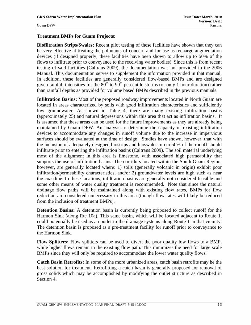
Treatment BMPs for Guam Projects:
Biofiltration Strips/Swales: Recent pilot testing of these facilities have shown that they can be very effective at treating the pollutants of concern and for use as recharge augmentation devices (if designed properly, these facilities have been shown to allow up to 50% of the flows to infiltrate prior to conveyance to the receiving water bodies). Since this is from recent testing of said facilities (Caltrans 2009), the documentation was not provided in the 2006 Manual. This documentation serves to supplement the information provided in that manual. In addition, these facilities are generally considered flow-based BMPs and are designed given rainfall intensities for the 80th to 90th percentile storms (of only 1 hour duration) rather than rainfall depths as provided for volume based BMPs described in the previous manuals.
Infiltration Basins: Most of the proposed roadway improvements located in North Guam are located in areas characterized by soils with good infiltration characteristics and sufficiently low groundwater. As shown in Table 4, there are many existing infiltration basins (approximately 25) and natural depressions within this area that act as infiltration basins. It is assumed that these areas can be used for the future improvements as they are already being maintained by Guam DPW. An analysis to determine the capacity of existing infiltration devices to accommodate any changes in runoff volume due to the increase in impervious surfaces should be evaluated at the time of design. Studies have shown, however, that with the inclusion of adequately designed biostrips and bioswales, up to 50% of the runoff should infiltrate prior to entering the infiltration basins (Caltrans 2009). The soil material underlying most of the alignment in this area is limestone, with associated high permeability that supports the use of infiltration basins. The corridors located within the South Guam Region, however, are generally located where: 1) soils (generally volcanic in origin) exhibit poor infiltration/permeability characteristics, and/or 2) groundwater levels are high such as near the coastline. In these locations, infiltration basins are generally not considered feasible and some other means of water quality treatment is recommended. Note that since the natural drainage flow paths will be maintained along with existing flow rates, BMPs for flow reduction are considered unnecessary in this area (though flow rates will likely be reduced from the inclusion of treatment BMPs).
Detention Basins: A detention basin is currently being proposed to collect runoff for the Harmon Sink (along Rte 10a). This same basin, which will be located adjacent to Route 1, could potentially be used as an outlet to the drainage systems along Route 1 in that vicinity. The detention basin is proposed as a pre-treatment facility for runoff prior to conveyance to the Harmon Sink.
Flow Splitters: Flow splitters can be used to divert the poor quality low flows to a BMP, while higher flows remain in the existing flow path. This minimizes the need for large scale BMPs since they will only be required to accommodate the lower water quality flows.
Catch Basin Retrofits: In some of the more urbanized areas, catch basin retrofits may be the best solution for treatment. Retrofitting a catch basin is generally proposed for removal of gross solids which may be accomplished by modifying the outlet structure as described in Section 4.

This page intentionally left blank

GRN Storm Water Implementation Plan Issue Date: March 2010 Version: Draft Guam DPW Parsons
GUAM_GRN_SW_IMPLEMENTATION_PLAN FINAL_DRAFT_3-15-10.DOC 7-1
SECTION 7 GRN STORMWATER MANAGEMENT CONCEPTS
7.1 OVERALL CONCEPT
Major runoff interception, conveyance and water pollution control elements of the GRN projects are described in this section. Where feasible, the overall drainage concepts should maintain existing drainage flow patterns and incorporate existing drainage systems and water quality control features as much as possible, given existing physical constraints. While this section provides overall concepts, each GRN project will need to have the drainage evaluated at a more detailed level during the design phase with proper drainage systems installed and existing problems corrected in accordance with guidelines provided in the Transportation Storm Water Manual and the 2006 Manual.
7.2 PROJECT CATEGORIES
The following sub-sections describe drainage conditions along the GRN corridors for onsite systems and offsite systems. In general, there are four categories of projects that require different storm water management strategies. These can be broken down into: 1) pavement widening which includes projects that will increase the impervious surface such as capacity improvements (i.e. addition of new lanes), pavement strengthening with shoulder widening, and new roadways; 2) pavement strengthening without shoulder widening; 3) intersection improvement projects that include signaling, striping, and possibly additional lanes that may result in minor increases of onsite impervious surfaces and 4) bridge crossing replacement projects which may affect conveyance of offsite flows under the roadway. Figures 13 and 14 depict the alignments of the combined GRN projects and show the limits of those projects requiring pavement widening along with the bridge replacement project locations. Table 6 summarizes the GRN project storm water management strategies for the four categories of projects. Table 7 at the end of this section provides a synopsis of the drainage conditions and potential BMPs to be used for the GRN Corridor Segments shown in these figures. General guidelines for water pollution control are described below for the various project categories:
Pavement Widening Projects – These involve pavement strengthening projects that include shoulder widening, capacity improvement projects that include construction of additional lanes, and new roadways, all of which result in an increase in onsite impervious surfaces. Construction site BMPs as described in Section 4.1 will be employed during construction for each project falling under this category (see Table 6). The Scope of Work for these projects will implement appropriate pollution source control and pollution treatment controls based on the drainage characteristics in Section 7.3 and 7.4.
Pavement Strengthening Projects (Without Shoulder Widening): These projects involve replacement of the existing structural segment of the roadway and do not involve increases in the pavement area. Without additional impervious surface, the existing drainage flow rates, patterns as well as the existing drainage system will be maintained. Construction BMPs as described in Section 4.1 will be employed during construction for each project falling under

GRN Storm Water Implementation Plan Issue Date: March 2010 Version: Draft Guam DPW Parsons
GUAM_GRN_SW_IMPLEMENTATION_PLAN FINAL_DRAFT_3-15-10.DOC 7-2
this category (see Table 6). In rural areas where curbs are not present, existing grass shoulders should be graded to drain away from the road to prevent concentrated flow along the pavement and subsequently improve drainage conditions (see Section 7.4). In doing so, the elevation of the pavement should be at grade or higher than the adjacent grass shoulder to ensure sheet flow through the grass. The grass shoulders and swales will both promote infiltration and provide treatment for the pollutants of concern. As shown in Figures 13 and 14, approximately 70% of the Guam projects fall within this category. Tables 6 and 7 display the Guam corridors and related projects which require strengthening. Intersection Improvement Projects - Intersection projects include improvements at roadway intersections and military access points and involve such items as signaling, striping, and in some instances additional lanes that may result in minor increases of onsite impervious surfaces. Construction BMPs as described in Section 4.1 will be employed during construction for intersection improvement projects which result in disturbed soils such as those requiring pavement widening for additional lanes (see Table 6). The intersections requiring pavement widening are shown in Figures 13 and 14. The Scope of Work for these projects will implement appropriate pollution source control and pollution treatment controls based on the drainage characteristics discussed in Section 7.3 and 7.4. Treatment related to pavement widening for these intersections should be accomplished at the outlet of the pipeline network if sufficient room is available for BMP placement at the outlet. This is recommended along Route 1 at the Tamuning Drainageway as described further in this section. Otherwise, catch basins at the intersections may be retrofitted for gross solids removal as described in Section 4.4.
Bridge Crossing Replacement Projects - Several bridge crossings are to be replaced along the rural portion of Route 1 (see Figure 14 and Appendix F). Bridges and associated approach slabs within all areas generally concentrate flow since they are curbed. As such, the on-site runoff from the bridges for this area should be directed to asphalt concrete (AC) spillways where curbs beyond the bridge approach slabs end. Some form of energy dissipation such as rip rap will be required at the downstream end of the AC spillway to prevent erosion. These bridges also provide conveyance of off-site flows under the roadway. Off-site runoff design requirements are generally limited to source control BMPs such as streambank stabilization. Embankment stabilization in the vicinity of the bridges is important since embankment erosion is evident at all bridge sites. In order to control the erosion, simple source control improvements are recommended. These include improvements such as the placement of rip rap or gabions along the river’s embankment immediately upstream and downstream of the bridges, concrete channel lining, or wing wall replacement where necessary. Tables 6 and 7 show the GRN corridors and related projects which require bridge crossing replacement.

GRN Storm Water Implementation Plan Issue Date: March 2010 Version: Draft Guam DPW Parsons
GUAM_GRN_SW_IMPLEMENTATION_PLAN FINAL_DRAFT_3-15-10.DOC 7-3
Table 6 – Summary of GRN Projects
Proj
ect T
ype
GRN
Proj
ect
Corri
dor S
egm
ent
Proj
ect L
imits
Exist
ing
Drain
age
Syst
em
Post
-Co
nstru
ctio
n So
urce
Con
trol
Post
-Co
nstru
ctio
n Tr
eatm
ent
Cont
rol
Prop
osed
Ons
ite
Drain
age
Impr
ovem
ents
North
Sout
h
Urba
n Ru
ral
Urba
n Ru
ral
Pave
men
t Stre
ngth
enin
g (W
ithou
t Sho
ulde
r Wid
enin
g)
6 Rte 1, Area 7 Rte 27 to Ch Lujana Sheet Flow Off
Pavement Exist Veg
Embankment Runoff Routed to Exist Infiltration Basins Not Anticipated x 7 Rte 1, Area 6 Rte 3 to Rte 27 Inlets & Storm Drain Exist Hardscape7 Runoff Routed to Exist Infiltration Basins Not Anticipated x
13 Rte 1, Area 2 Rte 11 to Asan River Sheet Flow Off
Pavement Exist Veg Sides Runoff to flow through exist grass shoulders Not Anticipated x
14 Rte 1, Area 2 Asan River to Rte 6 Sheet Flow Off
Pavement Exist Veg Sides Not Anticipated x
15 Rte 1, Area 2 Rte 6 to Rte 4 Sheet Flow Off
Pavement Exist Veg Sides Not Anticipated x
23 Rte 1, Area 7 Ch Lujana to Rte 9 Sheet Flow Off
Pavement Exist Veg
Embankment Runoff Routed to Exist Infiltration Basins Not Anticipated x
24 Rte 1, Area 1 Rte 11 to Rte 2A Sheet Flow Off
Pavement Exist Veg
Embankment Runoff to flow through exist grass shoulders Grade Biostrips to Drain x
33 Rte 1, Areas 3,
4, 5 Rte 8 to Rte 3 Inlets & Storm Drain Exist Hardscape
Catch Basin Retrofits Recommended for Area 3, BMP at Tamuning Drainageway for Area 4, Existing Detention at Harmon Sink for Area 5
Add Flow Splitter at Tamuning Drainage-way x x
8 Rte 3, Area 1 Rte 28 to Rte 1 Sheet Flow Off
Pavement Exist Veg
Embankment Runoff Routed to Exist Infiltration Basins Not Anticipated x
17 Rte 8, Area 2 Rte 10 to Tiyan Pk/ Rte 33 Inlets & Storm Drain Exist Hardscape & Veg Embankment Runoff Routed to Exist Infiltration Basins
Eliminate Localized Onsite Ponding x
30 Rte 10 Rte 15 to Rte 8 /16 Inlets & Storm Drain Exist Hardscape & Veg Embankment Runoff Routed to Exist Infiltration Basins Not Anticipated x
4 Rte 11 Port to Rte 1 Inlets & Storm Drain Exist Veg
Embankment Not Anticipated x
12 Rte 15 Smith Quarry to Ch Lujana Sheet Flow Off
Pavement Exist Veg
Embankment Runoff to flow through exist grass shoulders Not Anticipated x
18 Rte 16, Areas
2, 3 Rte 27 to Rte 10A Inlets & Storm Drain Exist Hardscape & Veg Embankment Runoff Routed to Exist Infiltration Basins Not Anticipated x
63 Rte 16, Area 1 Rte 10A to Sabana Barrigada
Sheet Flow Off Pavement
Exist Veg Embankment Runoff to flow through exist grass shoulders
Eliminate Localized Onsite Ponding x
21 Rte 27 Rte 1 to Rte 16 Inlets & Storm Drain Exist Hardscape & Veg Embankment Runoff Routed to Exist Infiltration Basins Not Anticipated x
7 Hardscape includes concrete-based, concentrated flow structures such as sidewalks, curb and gutter, etc.
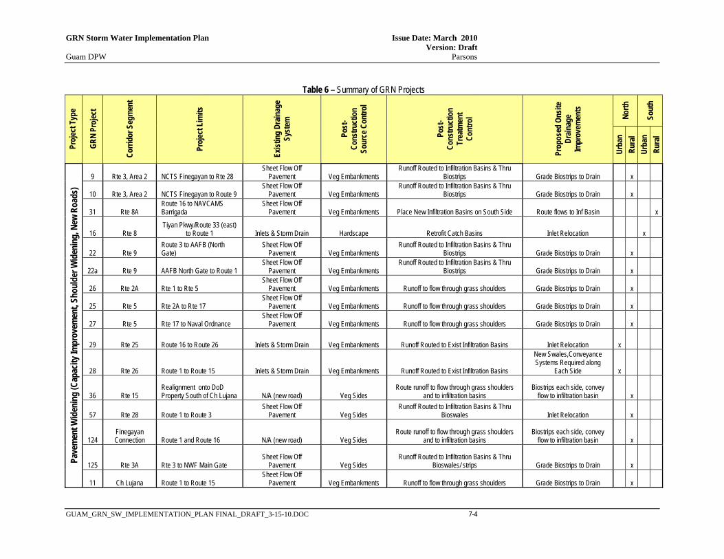
GRN Storm Water Implementation Plan Issue Date: March 2010 Version: Draft Guam DPW Parsons
GUAM_GRN_SW_IMPLEMENTATION_PLAN FINAL_DRAFT_3-15-10.DOC 7-4
Table 6 – Summary of GRN Projects
Proj
ect T
ype
GRN
Proj
ect
Corri
dor S
egm
ent
Proj
ect L
imits
Exist
ing
Drain
age
Syst
em
Post
-Co
nstru
ctio
n So
urce
Con
trol
Post
-Co
nstru
ctio
n Tr
eatm
ent
Cont
rol
Prop
osed
Ons
ite
Drain
age
Impr
ovem
ents
North
Sout
h
Urba
n Ru
ral
Urba
n Ru
ral
Pave
men
t Wid
enin
g (C
apac
ity Im
prov
emen
t, Sh
ould
er W
iden
ing,
New
Roa
ds)
9 Rte 3, Area 2 NCTS Finegayan to Rte 28 Sheet Flow Off
Pavement Veg Embankments Runoff Routed to Infiltration Basins & Thru
Biostrips Grade Biostrips to Drain x
10 Rte 3, Area 2 NCTS Finegayan to Route 9 Sheet Flow Off
Pavement Veg Embankments Runoff Routed to Infiltration Basins & Thru
Biostrips Grade Biostrips to Drain x
31 Rte 8A Route 16 to NAVCAMS Barrigada
Sheet Flow Off Pavement Veg Embankments Place New Infiltration Basins on South Side Route flows to Inf Basin x
16 Rte 8 Tiyan Pkwy/Route 33 (east)
to Route 1 Inlets & Storm Drain Hardscape Retrofit Catch Basins Inlet Relocation x
22 Rte 9 Route 3 to AAFB (North Gate)
Sheet Flow Off Pavement Veg Embankments
Runoff Routed to Infiltration Basins & Thru Biostrips Grade Biostrips to Drain x
22a Rte 9 AAFB North Gate to Route 1 Sheet Flow Off
Pavement Veg Embankments Runoff Routed to Infiltration Basins & Thru
Biostrips Grade Biostrips to Drain x
26 Rte 2A Rte 1 to Rte 5 Sheet Flow Off
Pavement Veg Embankments Runoff to flow through grass shoulders Grade Biostrips to Drain x
25 Rte 5 Rte 2A to Rte 17 Sheet Flow Off
Pavement Veg Embankments Runoff to flow through grass shoulders Grade Biostrips to Drain x
27 Rte 5 Rte 17 to Naval Ordnance Sheet Flow Off
Pavement Veg Embankments Runoff to flow through grass shoulders Grade Biostrips to Drain x
29 Rte 25 Route 16 to Route 26 Inlets & Storm Drain Veg Embankments Runoff Routed to Exist Infiltration Basins Inlet Relocation x
28 Rte 26 Route 1 to Route 15 Inlets & Storm Drain Veg Embankments Runoff Routed to Exist Infiltration Basins
New Swales,Conveyance Systems Required along
Each Side x
36 Rte 15 Realignment onto DoD Property South of Ch Lujana N/A (new road) Veg Sides
Route runoff to flow through grass shoulders and to infiltration basins
Biostrips each side, convey flow to infiltration basin x
57 Rte 28 Route 1 to Route 3 Sheet Flow Off
Pavement Veg Sides Runoff Routed to Infiltration Basins & Thru
Bioswales Inlet Relocation x
124 Finegayan Connection Route 1 and Route 16 N/A (new road) Veg Sides
Route runoff to flow through grass shoulders and to infiltration basins
Biostrips each side, convey flow to infiltration basin x
125 Rte 3A Rte 3 to NWF Main Gate Sheet Flow Off
Pavement Veg Sides Runoff Routed to Infiltration Basins & Thru
Bioswales/ strips Grade Biostrips to Drain x
11 Ch Lujana Route 1 to Route 15 Sheet Flow Off
Pavement Veg Embankments Runoff to flow through grass shoulders Grade Biostrips to Drain x

GRN Storm Water Implementation Plan Issue Date: March 2010 Version: Draft Guam DPW Parsons
GUAM_GRN_SW_IMPLEMENTATION_PLAN FINAL_DRAFT_3-15-10.DOC 7-5
Table 6 – Summary of GRN Projects
Proj
ect T
ype
GRN
Proj
ect
Corri
dor S
egm
ent
Proj
ect L
imits
Exist
ing
Drain
age
Syst
em
Post
-Co
nstru
ctio
n So
urce
Con
trol
Post
-Co
nstru
ctio
n Tr
eatm
ent
Cont
rol
Prop
osed
Ons
ite
Drain
age
Impr
ovem
ents
North
Sout
h
Urba
n Ru
ral
Urba
n Ru
ral
Inte
rsec
tion
Impr
ovem
ents
1 Rte 1, Area 3 Route 1 / Route 8 Intersection Inlets & Storm Drain Veg Embankments Retrofit Catch Basins Inlet Relocation x
2 Rte 1, Area 5 Route 1 / Route 3 Intersection Inlets & Storm Drain Veg Embankments Route SD to Detention at Harmon Sink Inlet Relocation x
6 Rte 1, Area 6 Route 1 / Route 28 Intersection Inlets & Storm Drain Veg Embankments Runoff Routed to Exist Infiltration Basins Inlet Relocation x
6 Rte 1, Area 6 Route 1 / Route 26 Intersection Inlets & Storm Drain Veg Embankments Runoff Routed to Exist Infiltration Basins Inlet Relocation x
7 Rte 1, Area 6 Route 1 / Route 27 Intersection Inlets & Storm Drain Veg Embankments Runoff Routed to Exist Infiltration Basins Inlet Relocation x
7 Rte 1, Area 6 Route 1 / Route 27A Intersection Inlets & Storm Drain Veg Embankments Runoff Routed to Exist Infiltration Basins Inlet Relocation x
33 Rte 1, Area 5 Route 1 / Route 14 (NSV) Intersection Inlets & Storm Drain Veg Embankments Route SD to Detention at Harmon Sink Inlet Relocation x
33 Rte 1, Area 5 Route 1 / Route 14A Intersection Inlets & Storm Drain Veg Embankments Route SD to Detention at Harmon Sink Inlet Relocation x
33 Rte 1, Area 5 Route 1 / Route 10A Intersection Inlets & Storm Drain Veg Embankments Route SD to Detention at Harmon Sink Inlet Relocation x
33 Rte 1, Area 4 Route 1 / Route 14B Intersection Inlets & Storm Drain Veg Embankments
Place Treatment BMP at Tamuning Drainageway Inlet Relocation x
33 Rte 1, Area 4 Route 1 / Route 14 (ITC) Intersection Inlets & Storm Drain Hardscape
Place Treatment BMP at Tamuning Drainageway Inlet Relocation x
33 Rte 1, Area 4 Route 1 / Route 30 Intersection Inlets & Storm Drain Hardscape
Place Treatment BMP at Tamuning Drainageway Inlet Relocation x
50 Rte 1, Area 7 Navy Main Base, Rte 1 @ Turner
Sheet Flow Off Pavement Veg Embankments
Runoff Routed to Infiltration Basins & Thru Biostrips Grade Biostrips to Drain x
124 Rte 1, Area 5 Route 1 / Route 16 Intersection Inlets & Storm Drain Veg Embankments Runoff Routed to Exist Infiltration Basins Inlet Relocation x
44 Rte 1, Area 7 Anderson South (Main Gate) Sheet Flow Off
Pavement Veg Embankments Runoff Routed to Exist Infiltration Basins Grade Biostrips to Drain x
9 Rte 3, Area 2 Route 3 / Route 28 Intersection
Sheet Flow Off Pavement Veg Embankments Runoff Routed to Biostrips & Infiltration Basins
N/A (No Changes to Pavement) x
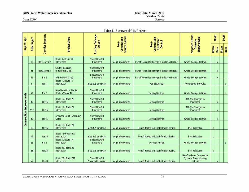
GRN Storm Water Implementation Plan Issue Date: March 2010 Version: Draft Guam DPW Parsons
GUAM_GRN_SW_IMPLEMENTATION_PLAN FINAL_DRAFT_3-15-10.DOC 7-6
Table 6 – Summary of GRN Projects
Proj
ect T
ype
GRN
Proj
ect
Corri
dor S
egm
ent
Proj
ect L
imits
Exist
ing
Drain
age
Syst
em
Post
-Co
nstru
ctio
n So
urce
Con
trol
Post
-Co
nstru
ctio
n Tr
eatm
ent
Cont
rol
Prop
osed
Ons
ite
Drain
age
Impr
ovem
ents
North
Sout
h
Urba
n Ru
ral
Urba
n Ru
ral
10 Rte 3, Area 2 Route 3 / Route 3A Intersection
Sheet Flow Off Pavement Veg Embankments Runoff Routed to Biostrips & Infiltration Basins Grade Biostrips to Drain x
41 Rte 3, Area 2 South Finegayan (Residential Gate)
Sheet Flow Off Pavement Veg Embankments Runoff Routed to Biostrips & Infiltration Basins Grade Biostrips to Drain x
42 Rte 9 AAFB (North Gate) Sheet Flow Off
Pavement Veg Embankments Runoff Routed to Biostrips & Infiltration Basins Grade Biostrips to Drain x 5 Rte 11
Route 1 / Route 11 Intersection Inlets & Storm Drain Veg Embankments Add Bioswales Route SD to Bioswales x
52 Rte 5 Naval Munitions Site @ Route 5/ Route 12
Sheet Flow Off Pavement Veg Embankments Existing Biostrips Grade Biostrips to Drain x
32 Rte 15 Route 15 / Route 26 Intersection
Sheet Flow Off Pavement Veg Embankments Existing Biostrips
N/A (No Changes to Pavement) x
117 Rte 15 Route 15 / Route 29 Intersection
Sheet Flow Off Pavement Veg Embankments Existing Biostrips
N/A (No Changes to Pavement) x
46 Rte 15 Anderson South (Secondary Gate)
Sheet Flow Off Pavement Veg Embankments Existing Biostrips Grade Biostrips to Drain x
18 Rte 16 Route 16 / Route 27 Intersection Inlets & Storm Drain Veg Embankments Runoff Routed to Exist Infiltration Basins Inlet Relocation x
19 Rte 16 Route 16/ Route 10A Intersection Inlets & Storm Drain Veg Embankments Runoff Routed to Exist Infiltration Basins Inlet Relocation x
25 Rte 5 Route 5 / Route 17 Intersection
Sheet Flow Off Pavement Veg Embankments Existing Biostrips Grade Biostrips to Drain x
28 Rte 26 Route 26 / Route 25 Intersection Inlets & Storm Drain Veg Embankments Runoff Routed to Exist Infiltration Basins Inlet Relocation x
57 Rte 28 Route 28 / Route 27A Intersection
Sheet Flow Off Pavement to Swales Veg Embankments Runoff Routed to Exist Infiltration Basins
New Swales or Conveyance Systems Required along
Each Side x
In
ters
ectio
n Im
prov
emen
ts

GRN Storm Water Implementation Plan Issue Date: March 2010 Version: Draft Guam DPW Parsons
GUAM_GRN_SW_IMPLEMENTATION_PLAN FINAL_DRAFT_3-15-10.DOC 7-7
Table 6 – Summary of GRN Projects
Proj
ect T
ype
GRN
Proj
ect
Corri
dor S
egm
ent
Proj
ect L
imits
Exist
ing
Drain
age
Syst
em
Post
-Co
nstru
ctio
n So
urce
Con
trol
Post
-Co
nstru
ctio
n Tr
eatm
ent
Cont
rol
Prop
osed
Ons
ite
Drain
age
Impr
ovem
ents
North
Sout
h
Urba
n Ru
ral
Urba
n Ru
ral
Brid
ge R
eplac
emen
t Pro
jects
3 Rte 1, Area 3 Agana Bridge Replacement Inlets & Storm Drain Rip rap, channel lining, wing walls See GRN 1
Retrofit Catch Basins at Downstream Side of Bridge x
35 Rte 1, Area 1 Fonte Bridge Replacement Sheet Flow Off
Pavement Rip rap, channel lining, wing walls See GRN 24
AC Spillway Downstream Side of Bridge. Rip Rap at
Base of Spillway. x
35 Rte 1, Area 1 Asan Bridge 2 Replacement Sheet Flow Off
Pavement Rip rap, channel lining, wing walls See GRN 24
AC Spillway Downstream Side of Bridge. Rip Rap at
Base of Spillway. x
35 Rte 1, Area 1 Asan Bridge 1 Replacement Sheet Flow Off
Pavement Rip rap, channel lining, wing walls See GRN 24
AC Spillway Downstream Side of Bridge. Rip Rap at
Base of Spillway. x
35 Rte 1, Area 1 Sasa Bridge Replacement Sheet Flow Off
Pavement Rip rap, channel lining, wing walls See GRN 24
AC Spillway Downstream Side of Bridge. Rip Rap at
Base of Spillway. x
35 Rte 1, Area 1 Laguas Bridge Replacement Sheet Flow Off
Pavement Rip rap, channel lining, wing walls See GRN 24
AC Spillway Downstream Side of Bridge. Rip Rap at
Base of Spillway. x
35 Rte 1, Area 1 Aguada Bridge Replacement
Sheet Flow Off Pavement
Rip rap, channel lining, wing walls See GRN 24
AC Spillway Downstream Side of Bridge. Rip Rap at
Base of Spillway. x
35 Rte 1, Area 1 Atantano Bridge Replacement
Sheet Flow Off Pavement
Rip rap, channel lining, wing walls See GRN 24
AC Spillway Downstream Side of Bridge. Rip Rap at
Base of Spillway. x
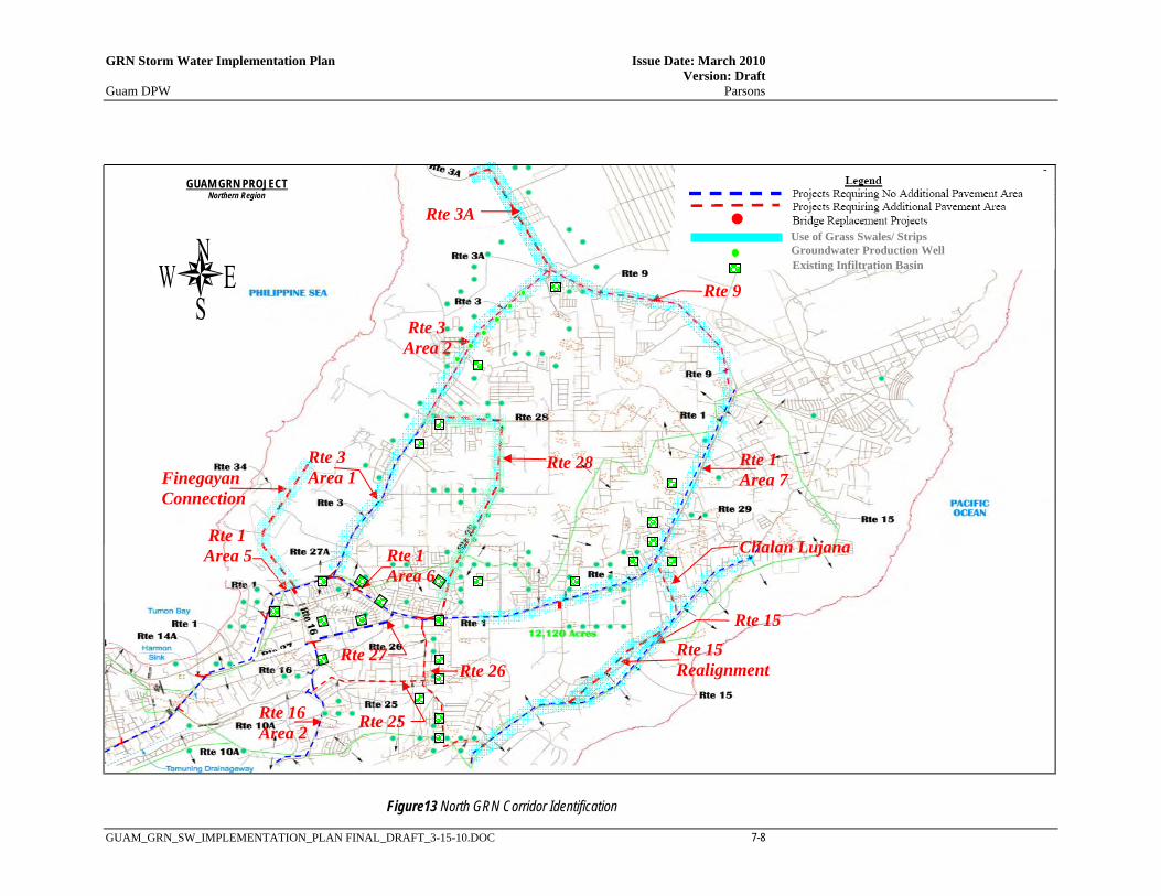
GRN Storm Water Implementation Plan Issue Date: March 2010 Version: Draft Guam DPW Parsons
GUAM_GRN_SW_IMPLEMENTATION_PLAN FINAL_DRAFT_3-15-10.DOC 7-8
Rte 1 Area 5
Rte 1 Area 6
Rte 1 Area 7
Rte 3 Area 1
Rte 3 Area 2
Rte 9
Rte 15
Rte 16 Area 2 Rte 25
Rte 26
Rte 27
Chalan Lujana
Use of Grass Swales/ Strips Groundwater Production Well
Rte 28
Existing Infiltration Basin
Figure13 North GRN Corridor Identification
Rte 3A
Finegayan Connection
Rte 15 Realignment
GUAM GRN PROJECT Northern Region

GRN Storm Water Implementation Plan Issue Date: March 2010 Version: Draft Guam DPW Parsons
GUAM_GRN_SW_IMPLEMENTATION_PLAN FINAL_DRAFT_3-15-10.DOC 7-9
Use of Grass Swales/ Strips Groundwater Well
Rte 11
Rte 1 Area 1
Rte 2A
Rte 5
Rte 1 Area 2
Rte 1 Area 4
Rte 1 Area 3
Rte 8 Area 1
Rte 8 Area 2
Rte 8A
Rte 10 Rte 15
Rte 16 Area 1
Existing Infiltration Basin
Figure 14 South GRN Corridor Identification
Asan River Bridge 1 Improvements
Asan River Bridge 2 Improvements
Sasa River Bridge Improvements

GRN Storm Water Implementation Plan Issue Date: March 2010 Version: Draft Guam DPW Parsons
GUAM_GRN_SW_IMPLEMENTATION_PLAN FINAL_DRAFT_3-15-10.DOC 7-10
7.3 GRN ONSITE DRAINAGE CHARACTERISTICS
Onsite drainage characteristics of the GRN projects are described in this section. Projects have been broken down into those located in rural and urbanized areas. Roadway cross-sections in rural areas are generally not curbed and allow onsite runoff to sheet flow from the roadway onto grass shoulders. Roadway cross-sections within urbanized areas are generally curbed due to right-of-way constraints. The latter generally possess concentrated flow conveyance systems consisting of inlets and storm drains conveying flow to a single point. Onsite storm water management strategies for these two types of drainage systems can vary substantially and are described separately in the following sections.
7.3.1 NORTH GUAM Road surfaces in this area are relatively flat and runoff generally flows by sheets onto grass shoulders and/or swales, then into existing depressions (sinks) or manmade infiltration devices where it percolates into the ground. In this way, the runoff from the road is generally filtered prior to its conveyance to the sinks or infiltration devices. Figure 13 depicts the proposed GRN within North Guam. Section 4.3 provides general information on biofiltration swales and strips. The discussion below provides an overview of the drainage patterns in the area. There may be minor localized ponding issues that should be addressed during design that may not be described in this section. Therefore, each project will require a specific drainage review that addresses localized ponding/flooding issues. Rural Areas - The corridors highlighted in blue in Figure 13 display road sections generally located in the more rural areas that have existing grass shoulders and/or swales generally of sufficient size to act as treatment BMPs for water pollution control of on-site drainage. GRN project designs for these areas should include road cross-sections that incorporate these existing features with grass shoulders designed to accommodate sheet flow (not concentrated flow) from the pavement as described in Section 4.4 (Biofiltration Strips). The existing sinks will act as outlets for the drainage systems. Capacity of existing infiltration devices to accommodate any changes in runoff volume due to the increase in impervious surfaces should be evaluated at the time of design. If infiltration capacity is insufficient to accommodate the widened roads, additional infiltration devices or increases in existing infiltration basin capacity may be required. Any new infiltration devices should be placed within government right-of-way and should be located as far as possible from any existing production wells (with a minimum separation distance of 1000 ft). Urbanized Areas - Corridors located in the more urban areas of North Guam convey flow directly to manmade infiltration devices or natural sinks generally through a storm drain network consisting of catch basins, pipelines and outfalls. The lowest and largest sink within this area is the Harmon Sink located along Route 1, immediately north of Route 10A. A detention basin is currently being proposed to collect runoff for the Harmon Sink along Route 10A. This same basin, which will be located adjacent to Route 1, could potentially be used as an outlet to the drainage systems along Route 1 in that vicinity. Proposed GRN roadway projects that entail pavement widening in the urbanized corridors include Rtes 25 and 26. Improvements are underway for these routes including storm drain interception and conveyance systems to infiltration basins, underground recharge systems and existing sinks.
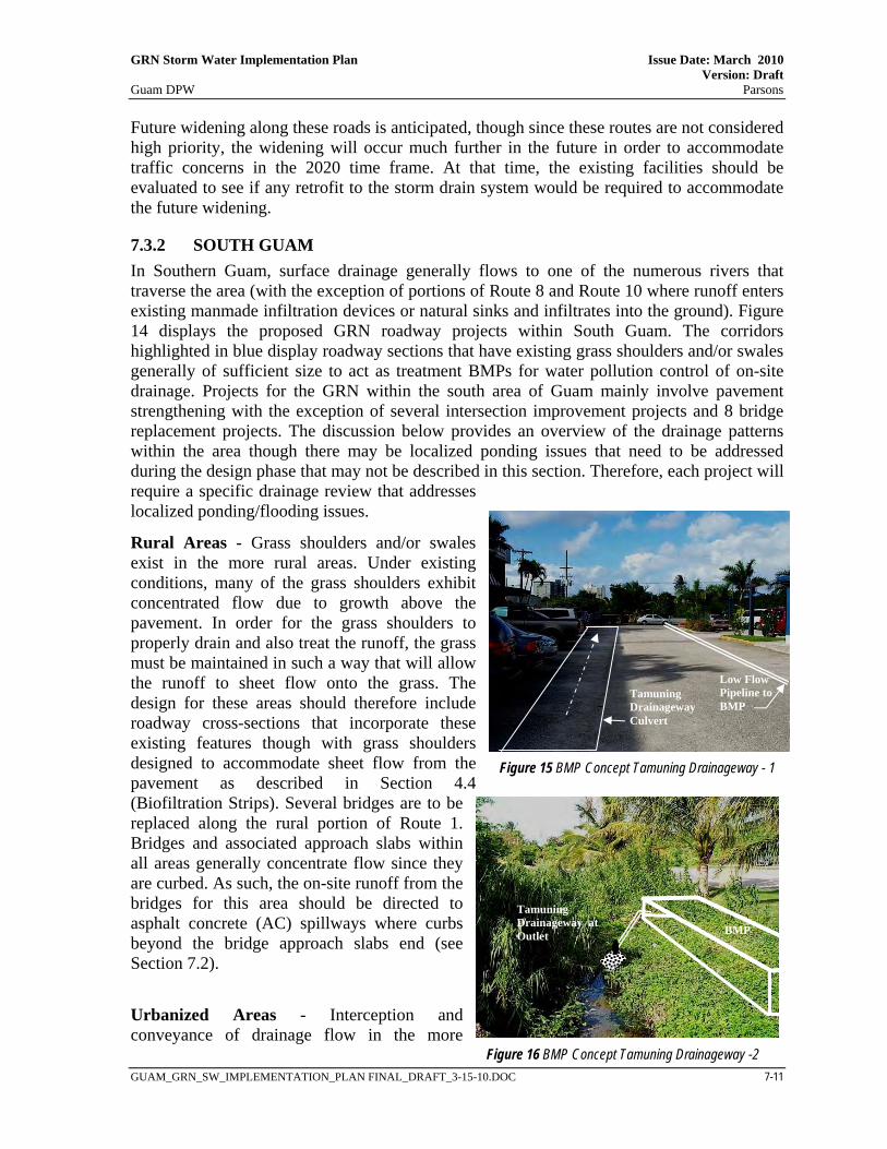
GRN Storm Water Implementation Plan Issue Date: March 2010 Version: Draft Guam DPW Parsons
GUAM_GRN_SW_IMPLEMENTATION_PLAN FINAL_DRAFT_3-15-10.DOC 7-11
Future widening along these roads is anticipated, though since these routes are not considered high priority, the widening will occur much further in the future in order to accommodate traffic concerns in the 2020 time frame. At that time, the existing facilities should be evaluated to see if any retrofit to the storm drain system would be required to accommodate the future widening.
7.3.2 SOUTH GUAM In Southern Guam, surface drainage generally flows to one of the numerous rivers that traverse the area (with the exception of portions of Route 8 and Route 10 where runoff enters existing manmade infiltration devices or natural sinks and infiltrates into the ground). Figure 14 displays the proposed GRN roadway projects within South Guam. The corridors highlighted in blue display roadway sections that have existing grass shoulders and/or swales generally of sufficient size to act as treatment BMPs for water pollution control of on-site drainage. Projects for the GRN within the south area of Guam mainly involve pavement strengthening with the exception of several intersection improvement projects and 8 bridge replacement projects. The discussion below provides an overview of the drainage patterns within the area though there may be localized ponding issues that need to be addressed during the design phase that may not be described in this section. Therefore, each project will require a specific drainage review that addresses localized ponding/flooding issues.
Rural Areas - Grass shoulders and/or swales exist in the more rural areas. Under existing conditions, many of the grass shoulders exhibit concentrated flow due to growth above the pavement. In order for the grass shoulders to properly drain and also treat the runoff, the grass must be maintained in such a way that will allow the runoff to sheet flow onto the grass. The design for these areas should therefore include roadway cross-sections that incorporate these existing features though with grass shoulders designed to accommodate sheet flow from the pavement as described in Section 4.4 (Biofiltration Strips). Several bridges are to be replaced along the rural portion of Route 1. Bridges and associated approach slabs within all areas generally concentrate flow since they are curbed. As such, the on-site runoff from the bridges for this area should be directed to asphalt concrete (AC) spillways where curbs beyond the bridge approach slabs end (see Section 7.2).
Urbanized Areas - Interception and conveyance of drainage flow in the more
Tamuning Drainageway Culvert
Low Flow Pipeline to BMP
Figure 15 BMP Concept Tamuning Drainageway - 1
Tamuning Drainageway at Outlet BMP
Figure 16 BMP Concept Tamuning Drainageway -2

GRN Storm Water Implementation Plan Issue Date: March 2010 Version: Draft Guam DPW Parsons
GUAM_GRN_SW_IMPLEMENTATION_PLAN FINAL_DRAFT_3-15-10.DOC 7-12
urbanized areas of the GRN in South Guam is accomplished with existing catch basins and storm drains. These include storm drain networks along Route 1 and Route 8 within the village of Agana and along Route 1 within the village of Tamuning. In Agana, Route 1 drainage systems outlet directly to Agana Bay and Route 8 drainage systems outlet directly to the Agana River. Here, water pollution control may be accomplished through catch basin retrofits (right of way and groundwater constraints seemingly prevent effective use of other BMP options). As described in Section 4.4, catch basins would be retrofitted to accommodate gross solids removal with some percolation through the bottom of the structure.
The drainage system for Route 1 in the vicinity of Tamuning is a large storm drain system that conveys flow to a single point of concentration, the Tamuning Drainageway. Strategic placement of a BMP at this location would enable treatment for several upstream projects. During design, the feasibility of a flow splitter placed in the on-site storm drain system at the Tamuning Drainageway should be evaluated. This could allow low flow roadway runoff to be directed to a treatment BMP located off-site, preferably on public property (see Figures 15 and 16). This may require a right of way easement for the incorporation of a low flow pipeline to the BMP location. Potential treatment for this location includes construction of a bioswale or media filter at the outlet.
7.4 GRN OFFSITE DRAINAGE CHARACTERISTICS
7.4.1 NORTH GUAM Since North Guam has no perennial streams and rainfall percolates rapidly through the surficial soils, there are very few drainage concerns regarding offsite runoff in this area. One area of concern is along Route 27, south of Route 16 where inadequate drainage conveyance causes offsite and onsite flow to intermingle and pond along the roadway. While this area is not within the purview of the GRN, it is being identified as a project of importance to be addressed in the overall Guam Transportation Improvement Program (GTIP).
7.4.2 SOUTH GUAM Proposed GRN projects within South Guam are generally on the west side of the island where the streams are channeled within the volcanic slopes which outlet into shallow fringing coral reefs. This section provides additional information regarding off-site drainage issues that should be addressed during the design phase of the GRN projects. Appendix F provides additional information regarding off-site conditions at each of the bridge replacement project sites.
Off-Site Coastal Issues: Route 1 parallels the coastline from Apra Harbor, northward to Agana Bay. Along this section of roadway, several locations are designated within FEMA
Figure 17: Coastal Erosion Protection along Rte 1

GRN Storm Water Implementation Plan Issue Date: March 2010 Version: Draft Guam DPW Parsons
GUAM_GRN_SW_IMPLEMENTATION_PLAN FINAL_DRAFT_3-15-10.DOC 7-13
Flood Hazard Zone V or VE which is defined as a coastal flood zone with velocity hazard due to wave action. Currently, these areas are protected from erosion by gabion walls or rip rap slope protection. Figure 17 shows a typical area along Route 1 within the coastal flood zone and where coastal erosion control has been used along the embankment in the form of riprap revetment. Field investigations indicate that several sections of the coastline within the limits of Route 1, Area 2 (see Figure 14) have little to no protection. Coastal erosion appears to encroach into the roadway right-of-way at one or two locations within this area. Offsite Flooding Issues: Flooding is prevalent along Route 1 in the vicinity of Apra Harbor from the Sasa River Bridge to the Atantano River Bridge (designated as Route 1, Area 1 in Figure 14). Here, the roadway is located above the tidal zone of the various rivers that flow to Apra Harbor. It has been noted that at periods of high tide and high flow in the river, the river’s water surface is elevated above the outer pavement for Route 1 (which is generally crowned in this area). This has been observed to occur at a frequency of approximately once every two years. Figure 18 displays a cross-culvert in this area during normal high tide condition. The only way to remedy this situation is to raise the road surface which is beyond the scope of the GRN projects since the only work to be done in this area is with respect to pavement strengthening. In order to improve the drainage in this area (i.e. the area designated as Route 1, Area 1 in Figure 14), it is recommended that the grass shoulders be graded to drain (currently the grass shoulder is allowed to grow onto the pavement causing flow to concentrate along the edge of pavement, rendering sheet flow ineffective). The level of the adjacent ground surface should be at the elevation of the edge of pavement and the grass shoulders should slope away from the pavement. This will: 1) improve the drainage characteristics for this area, 2) enable use of the grass shoulders as treatment devices, 3) promote infiltration of the roadway runoff prior to entering the offsite receiving waters, and 4) improve flooding characteristics from offsite flows.
7.5 GRN STORM WATER MANAGEMENT SUMMARY
Table 7 below provides a synopsis of the various elements used in determining the appropriate on-site storm water management facilities for the various GRN corridors. The corridors have been segmented, where necessary, to separate areas exhibiting different drainage system characteristics and/or different water quality control requirements.
Figure 18: Route 1 Flood Prone Area – Apra Harbor

GRN Storm Water Implementation Plan Issue Date: March 2010 Version: Draft Guam DPW Parsons
GUAM_GRN_SW_IMPLEMENTATION_PLAN FINAL_DRAFT_3-15-10.DOC 7-14
Table 7 – Summary of GRN Storm Water Management Components
GRN Location (Figures 13 and
14)
Added Paved Area?
Water Quality Classi-fication
General Location Length (ft)
Total New Imp-
ervious Area (ac)
Total Disturbed Area (ac)
Is Onsite Flow
Concentrated?
Is There Adequate Area for
Biofiltration Devices?
Are Soils and Groundwater
Depths Adequate for Infiltration?
Is Area Tributary to NGL
Aquifer? Potential BMPs Remarks
Rte 1, Area 1 No Moderate South Guam, Apra Harbor Area 16,247 0.0 17.9 No Yes No No Bioswales/ strips See Section 7 for exist flooding issues.
Rte 1, Area 2 No Moderate South Guam, Piti Bay Area 24,009 0.0 31.5 No Some
Locations No No Bioswales/ strips Rte 1, Area 3 No Moderate South Guam, Agana Bay Area 9,042 0.0 14.9 Yes No No No CB Retrofits
Rte 1, Area 4 At Inter-sect’ns Moderate South Guam, Tamuning 9,042 1.0 15.9 Yes No No No
Flow Splitter, Media Filter or Bioswale
See Section 7 for BMP location.
Rte 1, Area 5 No Moderate North Guam, Harmon Sink 13,563 0.0 22.4 Yes No Yes Yes Exist Infiltration See Figure 13 for exist infiltration basins
Rte 1, Area 6 No Moderate North Guam, Rte 3 to Rte 28 6,867 0.0 11.4 Yes No Yes Yes Exist Infiltration See Figure 13 for exist infiltration basins
Rte 1, Area 7 No Moderate North Guam, Rte 28 to Rte 9 30,450 0.0 33.6 No Yes Yes Yes Exist Infiltration See Figure 13 for exist infiltration basins
Rte 2A No Moderate South Guam, Atantano Watershed 4,577 0.0 5.0 No Yes Yes No Bioswales/ strips
Rte 3, Area 1 No Moderate North Guam, Rte 1 to Rte 28 13,500 0.0 14.9 No Yes Yes Yes Bioswales/ strips, Exist
Infiltration See Figure 13 for exist infiltration basins
Rte 3, Area 2 Yes Moderate North Guam, Rte 28 to Rte 9 16,050 14.7 23.6 No Yes Yes Yes Bioswales/ strips, Exist
Infiltration See Figure 13 for exist infiltration basins
Rte 3A Yes Moderate North Guam, Rte 3 to Main Gate 9,500 3.5 8.7 No Yes Yes Yes Bioswales/ strips, Infiltration Rte 5 Yes Moderate South Guam, Atantano Watershed 10,333 3.8 9.5 No Yes Yes No Bioswales/ strips
Rte 8, Area 1 No Moderate South Guam, Rte 1 to Airport 8,290 0.0 13.7 Yes No No No CB Retrofits
Rte 8, Area 2 No Moderate South Guam, Airport Area 7,904 0.0 8.7 No Yes Yes Yes Bioswales/ strips, Existing
Injection Wells w/ Infiltration Rte 8A Yes Moderate South Guam, East of Rte 10 8,865 3.3 8.2 No Yes Yes Yes Bioswales/ strips, Infiltration
Rte 9 Yes Moderate North Guam, Rte 3 to Rte 1 15,500 8.5 17.1 No Yes Yes Yes Bioswales/ strips, Infiltration See Figure 13 for exist infiltration basins
Rte 10 No Moderate South Guam, Rte 8 to Rte 15 7,847 0.0 8.6 Yes No Yes Yes Exist Infiltration See Figure 14 for exist infiltration basins
Rte 11 No Moderate South Guam, Apra Harbor Area 10,630 0.0 5.9 Yes Yes No No Bioswales/ strips
Rte 15 No Moderate North/ South Guam, Rte 10 to Quarry North of Chalan Lujana 47,600 0.0 26.2 No Yes Yes Yes Bioswales/ strips
Rte 15 Realignment Yes Moderate
North Guam, Rte 15 South of Ch Lujana 11,200 7.7 15.4 No Yes Yes Yes Bioswales/ strips, infiltration
Rte 16, Area 1 No Moderate South Guam, Rte 8 to Rte 10A 8,691 0.0 9.6 No Yes Yes Yes Bioswales/ strips
Rte 16, Area 2 Yes Moderate North Guam at Rte 10A 5,448 3.0 9.0 Yes No Yes Yes Exist Infiltration See Figure 13 for exist infiltration basins
Rte 16, Area 3 No Moderate North Guam, Rte 10A to Rte 27 4,505 0.0 7.4 Yes No Yes Yes Exist Infiltration See Figure 13 for exist infiltration basins
Rte 25 Yes Moderate North Guam, Rte 16 to Rte 26 8,050 2.2 8.9 Yes No Yes Yes Exist Infiltration See Figure 13 for exist infiltration basins
Rte 26 Yes Moderate North Guam, Rte 15 to Rte 1 12,900 3.6 14.2 Yes No Yes Yes Exist Infiltration See Figure 13 for exist infiltration basins
Rte 27 No Moderate North Guam, Rte 16 to Rte 1 5,448 0.0 9.0 Yes No Yes Yes Exist Infiltration See Figure 13 for exist infiltration basins
Rte 28 Yes Moderate North Guam, Rte 1 to Rte 3 21,000 13.5 25.1 No Yes Yes Yes Bioswales/ strips, Exist
Infiltration See Figure 13 for exist infiltration basins
Chalan Lujana Yes Moderate North Guam, Rte 15 to Rte 1 4,350 1.2 3.6 No Yes Yes Yes Bioswales/ strips, Infiltration Finegayan Conn Yes Moderate North Guam, Rte 1 & Rte 16 18,910 17.4 30.4 No Yes Yes Yes Bioswales/ strips, Infiltration
GRN Storm Water Implementation Plan Issue Date: March 2010 Version: Draft Guam DPW Parsons
GUAM_GRN_SW_IMPLEMENTATION_PLAN FINAL_DRAFT_3-15-10.DOC 8-1
SECTION 8
REFERENCES
California Department of Transportation (Caltrans). 2007. Project Planning and Design Guide. March
Caltrans. 2003. Stormwater Quality Handbooks. March
Caltrans. 2001. Stormwater Management Plan. August
Caltrans. 2008. Biofiltration Strips Design Guidance. November
Caltrans. 2009. Biofiltration Swale Design Guidance. October
Caltrans. 2008. BMP Standard Details: Flow Splitters - Design Guidance. December
Caltrans. 2007. Treatment BMP Technology Report. April
Caltrans. 2003. Discharge Characterization Study Report. November
Caltrans. 2004. BMP Retrofit Pilot Program.
Caltrans. 2007. Stormwater Monitoring and Research Program Annual Data Summary Report. February.
Clean Water Action Plan for Guam. 1998. Clean Water Action Plan for Guam - Unified Watershed Assessment. September.
FIRMs. 2009. Web site: http://www.fema.gov/. Accessed 30 March 2009.
GEPA. 1994. The Safe Drinking Water Act.
GEPA. 1997. Guam Erosion and Sediment Control Regulations Fact Sheet. November.
GEPA. 1998. Water Quality Certification Application 401C. July.
GEPA. 1999. Water Quality Standards Revisions. December.
GEPA. 2000. Management of Contaminated Harbor Sediments in Guam, Coastal Zone Management Act Section 309, Guam Harbors Sediment Project Phase III Final Report. September.
GEPA. 2001. Guam Water Quality Standards. August.
GEPA. 2006. Integrated Report for the Clean Water Act Sections 303(d), 305(b) and 314. September.
GEPA. 2010. Guam Erosion Control and Stormwater Management Draft Regulations. Janaury 2010.
GovGuam. 1994. The Water Resources Conservation Act.

GRN Storm Water Implementation Plan Issue Date: March 2010 Version: Draft Guam DPW Parsons
GUAM_GRN_SW_IMPLEMENTATION_PLAN FINAL_DRAFT_3-15-10.DOC 8-2
GovGuam. 2008. The Guam Mapbook. Bureau of Statistics and Plans. January.
Parsons. 2010. Draft Transportation Stormwater Drainage Manual. January 2010.
Parsons. 2010. Draft Stormwater Drainage Master Plan. (In progress).
USACE. 2005. Quality Control Plan (QCP) and Independent Technical Review (ITR) Plan for Hagatna River Flood Contol Territory of Guam. May.
GRN Storm Water Implementation Plan Issue Date: March 2010 Version: Draft Guam DPW Parsons
GUAM_GRN_SW_IMPLEMENTATION_PLAN FINAL_DRAFT_3-15-10.DOC
APPENDIX A GRN PROJECT SPREADSHEET

This page intentionally left blank

GRN Storm Water Implementation Plan Issue Date: March 2010 Version: Draft Guam DPW Parsons
GUAM_GRN_SW_IMPLEMENTATION_PLAN FINAL_DRAFT_3-15-10.DOC
Rte Segment Limits Type of Work Requirements/Description GRN #
Length (ft)
Construction Year
1 Route 1 / Route 8 Intersection Intersection Improvements Intersection Improvements (.15 mi on Rte 1 & .09 mi on Rte 8) to provide two left-turn lanes and two right-turn lanes for northbound Route 8 approaching Route 1. 1 940 2010
1 Route 1 / Route 3 Intersection Intersection Improvements Intersection Improvements (.24 mi on Rte 1 & .04 mi on Rte 3) to provide southbound left, combined left/right, and free right with accel lane; east to north double left-turn lane. 2 2,400 2010
1 Agana Bridge Bridge Replacement Agana Bridge Replacement 3 85 2010 1 Route 27 to Chalan Lujana Pavement Strengthening Pavement strengthening (four lanes)
6 18,200 Not Scheduled 1 Route 1 / Route 28
Intersection Intersection Improvements Intersection improvements to provide additional eastbound left-turn lane; southbound Route 28 approach to include two right-turn lanes and combined left/through lane.
1 Route 1 / Route 26 Intersection Intersection Improvements
Intersection improvements to provide additional westbound left-turn lane, eastbound right-turn lane; northbound Route 26 approach to include left-turn, combined left-turn/right-turn, and right-turn lane.
1 Route 3 to Route 27 Pavement Strengthening Pavement strengthening (six lanes)
7 4,600 Not Scheduled 1 Route 1 / Route 27 Intersection Intersection Improvements
Intersection improvements to provide double eastbound left-turn lanes, eastbound right-turn lane, and triple westbound left-turn lanes. Northbound Route 27 approach to include left-turn, combined left-turn/through and two right-turn lanes.
1 Route 1 / Route 27A Intersection Intersection Improvements Intersection improvements to provide additional eastbound left-turn lane, additional
northbound Route 27A right-turn lane. 1 Route 11 to Asan River Pavement Strengthening Pavement strengthening (four lanes) 13 8,472 Not Scheduled
1 Asan River to Route 6 (Adelup) Pavement Strengthening Pavement strengthening (four lanes) 14 6,437 Not Scheduled
1 Route 6 (Adelup) to Route 4 Pavement Strengthening Pavement strengthening (six lanes) 15 9,100 Not Scheduled
1 Chalan Lujana to Route 9 (AAFB) Pavement Strengthening Pavement strengthening (four lanes) 23 14,250 Not Scheduled
1 Route 11 to Route 2A Pavement Strengthening Pavement strengthening (four lanes) 24 16,247 Not Scheduled 1 Route 8 to Route 3 Pavement Strengthening Pavement strengthening (six lanes)
33 31,647 Not Scheduled
1 Route 1 / Route 14 (NSV) Intersection Intersection Improvements Intersection improvements to add southbound right-turn lane.
1 Route 1 / Route 14A Intersection Intersection Improvements Intersection improvements to add northbound and southbound left-turn lanes,
southbound right-turn lane.
1 Route 1 / Route 10A Intersection Intersection Improvements Intersection improvements to add southbound left-turn lane, northbound right-turn lane.
1 Route 1 / Route 14B Intersection Intersection Improvements Intersection improvements to change eastbound right-turn lane to combined right-
turn/left-turn lane.
1 Route 1 / Route 14 (ITC) Intersection Intersection Improvements Intersection improvements to include southbound right-turn lane.
1 Route 1 / Route 30 Intersection Intersection Improvements
Intersection improvements to provide additional northbound left-turn lane, change existing lanes on eastbound approach to combined left-turn/through, and two right-turn lanes.
1 7 Bridge Replacements Bridge Replacement Replace Bridges (Atantano, Aguada, Laguas, Sasa, Fonte, Asan 1, Asan 2) 35 364 Not Scheduled
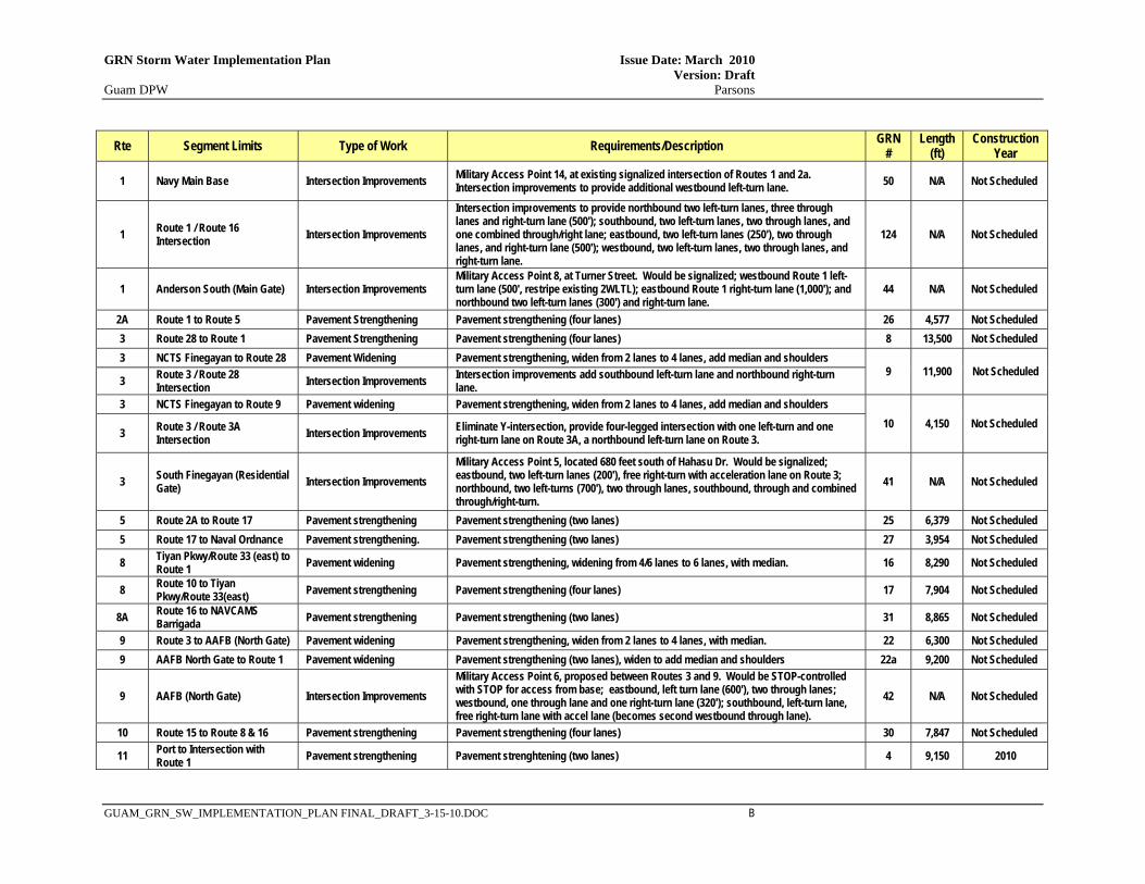
GRN Storm Water Implementation Plan Issue Date: March 2010 Version: Draft Guam DPW Parsons
GUAM_GRN_SW_IMPLEMENTATION_PLAN FINAL_DRAFT_3-15-10.DOC B
Rte Segment Limits Type of Work Requirements/Description GRN #
Length (ft)
Construction Year
1 Navy Main Base Intersection Improvements Military Access Point 14, at existing signalized intersection of Routes 1 and 2a. Intersection improvements to provide additional westbound left-turn lane. 50 N/A Not Scheduled
1 Route 1 / Route 16 Intersection Intersection Improvements
Intersection improvements to provide northbound two left-turn lanes, three through lanes and right-turn lane (500'); southbound, two left-turn lanes, two through lanes, and one combined through/right lane; eastbound, two left-turn lanes (250'), two through lanes, and right-turn lane (500'); westbound, two left-turn lanes, two through lanes, and right-turn lane.
124 N/A Not Scheduled
1 Anderson South (Main Gate) Intersection Improvements Military Access Point 8, at Turner Street. Would be signalized; westbound Route 1 left-turn lane (500', restripe existing 2WLTL); eastbound Route 1 right-turn lane (1,000'); and northbound two left-turn lanes (300') and right-turn lane.
44 N/A Not Scheduled
2A Route 1 to Route 5 Pavement Strengthening Pavement strengthening (four lanes) 26 4,577 Not Scheduled 3 Route 28 to Route 1 Pavement Strengthening Pavement strengthening (four lanes) 8 13,500 Not Scheduled 3 NCTS Finegayan to Route 28 Pavement Widening Pavement strengthening, widen from 2 lanes to 4 lanes, add median and shoulders
9 11,900 Not Scheduled 3 Route 3 / Route 28
Intersection Intersection Improvements Intersection improvements add southbound left-turn lane and northbound right-turn lane.
3 NCTS Finegayan to Route 9 Pavement widening Pavement strengthening, widen from 2 lanes to 4 lanes, add median and shoulders 10 4,150 Not Scheduled
3 Route 3 / Route 3A Intersection Intersection Improvements Eliminate Y-intersection, provide four-legged intersection with one left-turn and one
right-turn lane on Route 3A, a northbound left-turn lane on Route 3.
3 South Finegayan (Residential Gate) Intersection Improvements
Military Access Point 5, located 680 feet south of Hahasu Dr. Would be signalized; eastbound, two left-turn lanes (200'), free right-turn with acceleration lane on Route 3; northbound, two left-turns (700'), two through lanes, southbound, through and combined through/right-turn.
41 N/A Not Scheduled
5 Route 2A to Route 17 Pavement strengthening Pavement strengthening (two lanes) 25 6,379 Not Scheduled 5 Route 17 to Naval Ordnance Pavement strengthening. Pavement strengthening (two lanes) 27 3,954 Not Scheduled
8 Tiyan Pkwy/Route 33 (east) to Route 1 Pavement widening Pavement strengthening, widening from 4/6 lanes to 6 lanes, with median. 16 8,290 Not Scheduled
8 Route 10 to Tiyan Pkwy/Route 33(east) Pavement strengthening Pavement strengthening (four lanes) 17 7,904 Not Scheduled
8A Route 16 to NAVCAMS Barrigada Pavement strengthening Pavement strengthening (two lanes) 31 8,865 Not Scheduled
9 Route 3 to AAFB (North Gate) Pavement widening Pavement strengthening, widen from 2 lanes to 4 lanes, with median. 22 6,300 Not Scheduled 9 AAFB North Gate to Route 1 Pavement widening Pavement strengthening (two lanes), widen to add median and shoulders 22a 9,200 Not Scheduled
9 AAFB (North Gate) Intersection Improvements Military Access Point 6, proposed between Routes 3 and 9. Would be STOP-controlled with STOP for access from base; eastbound, left turn lane (600'), two through lanes; westbound, one through lane and one right-turn lane (320'); southbound, left-turn lane, free right-turn lane with accel lane (becomes second westbound through lane).
42 N/A Not Scheduled
10 Route 15 to Route 8 & 16 Pavement strengthening Pavement strengthening (four lanes) 30 7,847 Not Scheduled
11 Port to Intersection with Route 1 Pavement strengthening Pavement strenghtening (two lanes) 4 9,150 2010
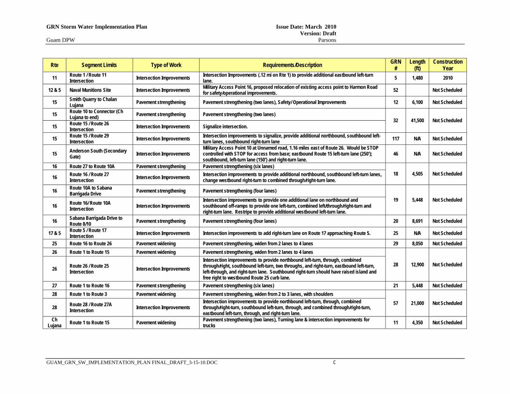
GRN Storm Water Implementation Plan Issue Date: March 2010 Version: Draft Guam DPW Parsons
GUAM_GRN_SW_IMPLEMENTATION_PLAN FINAL_DRAFT_3-15-10.DOC C
Rte Segment Limits Type of Work Requirements/Description GRN #
Length (ft)
Construction Year
11 Route 1 / Route 11 Intersection Intersection Improvements Intersection Improvements (.12 mi on Rte 1) to provide additional eastbound left-turn
lane. 5 1,480 2010
12 & 5 Naval Munitions Site Intersection Improvements Military Access Point 16, proposed relocation of existing access point to Harmon Road for safety/operational improvements. 52 Not Scheduled
15 Smith Quarry to Chalan Lujana Pavement strengthening Pavement strengthening (two lanes), Safety/ Operational Improvements 12 6,100 Not Scheduled
15 Route 10 to Connector (Ch Lujana to end) Pavement strengthening Pavement strengthening (two lanes)
32 41,500 Not Scheduled 15 Route 15 / Route 26
Intersection Intersection Improvements Signalize intersection.
15 Route 15 / Route 29 Intersection Intersection Improvements Intersection improvements to signalize, provide additional northbound, southbound left-
turn lanes, southbound right-turn lane 117 N/A Not Scheduled
15 Anderson South (Secondary Gate) Intersection Improvements
Military Access Point 10 at Unnamed road, 1.16 miles east of Route 26. Would be STOP controlled with STOP for access from base; eastbound Route 15 left-turn lane (250'); southbound, left-turn lane (150') and right-turn lane.
46 N/A Not Scheduled
16 Route 27 to Route 10A Pavement strengthening Pavement strengthening (six lanes) 18 4,505 Not Scheduled 16 Route 16 / Route 27
Intersection Intersection Improvements Intersection improvements to provide additional northbound, southbound left-turn lanes, change westbound right-turn to combined through/right-turn lane.
16 Route 10A to Sabana Barrigada Drive Pavement strengthening Pavement strengthening (four lanes)
19 5,448 Not Scheduled 16 Route 16/ Route 10A
Intersection Intersection Improvements Intersection improvements to provide one additional lane on northbound and southbound off-ramps to provide one left-turn, combined left/through/right-turn and right-turn lane. Restripe to provide additional westbound left-turn lane.
16 Sabana Barrigada Drive to Route 8/10 Pavement strengthening Pavement strengthening (four lanes) 20 8,691 Not Scheduled
17 & 5 Route 5 / Route 17 Intersection Intersection Improvements Intersection improvements to add right-turn lane on Route 17 approaching Route 5. 25 N/A Not Scheduled
25 Route 16 to Route 26 Pavement widening Pavement strengthening, widen from 2 lanes to 4 lanes 29 8,050 Not Scheduled 26 Route 1 to Route 15 Pavement widening Pavement strengthening, widen from 2 lanes to 4 lanes
28 12,900 Not Scheduled 26 Route 26 / Route 25
Intersection Intersection Improvements Intersection improvements to provide northbound left-turn, through, combined through/right, southbound left-turn, two throughs, and right-turn, eastbound left-turn, left-through, and right-turn lane. Southbound right-turn should have raised island and free right to westbound Route 25 curb lane.
27 Route 1 to Route 16 Pavement strengthening Pavement strengthening (six lanes) 21 5,448 Not Scheduled 28 Route 1 to Route 3 Pavement widening Pavement strengthening, widen from 2 to 3 lanes, with shoulders
57 21,000 Not Scheduled 28 Route 28 / Route 27A
Intersection Intersection Improvements Intersection improvements to provide northbound left-turn, through, combined through/right-turn, southbound left-turn, through, and combined through/right-turn, eastbound left-turn, through, and right-turn lane.
Ch Lujana Route 1 to Route 15 Pavement widening Pavement strengthening (two lanes), Turning lane & intersection improvements for
trucks 11 4,350 Not Scheduled

This page intentionally left blank
GRN Storm Water Implementation Plan Issue Date: March 2010 Version: Draft Guam DPW Parsons
GUAM_GRN_SW_IMPLEMENTATION_PLAN FINAL_DRAFT_3-15-10.DOC
APPENDIX B EXISTING INFILTRATION BASIN SITE MAPS

This page intentionally left blank
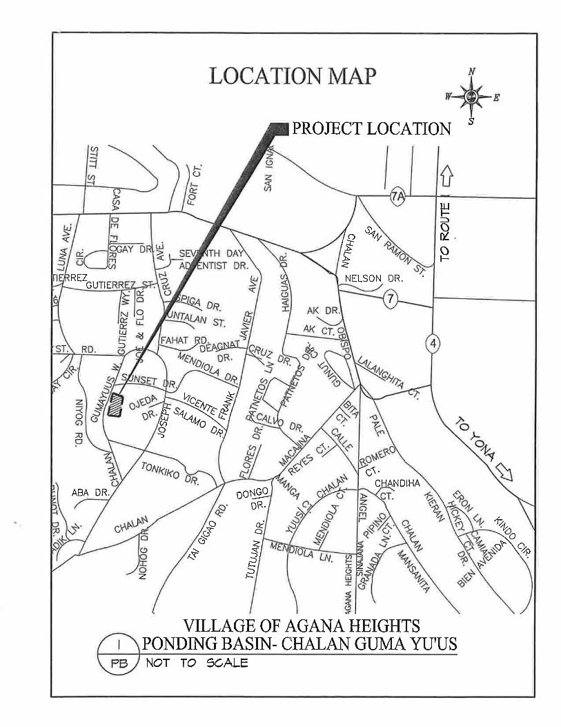
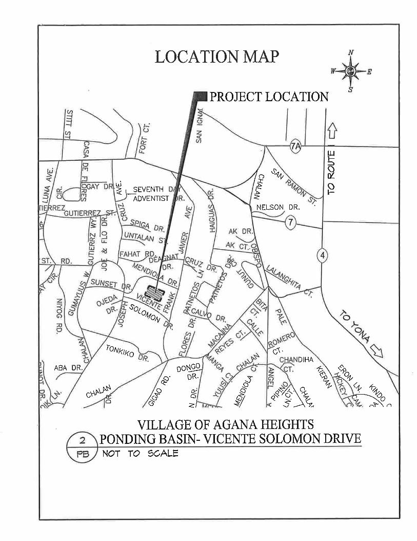
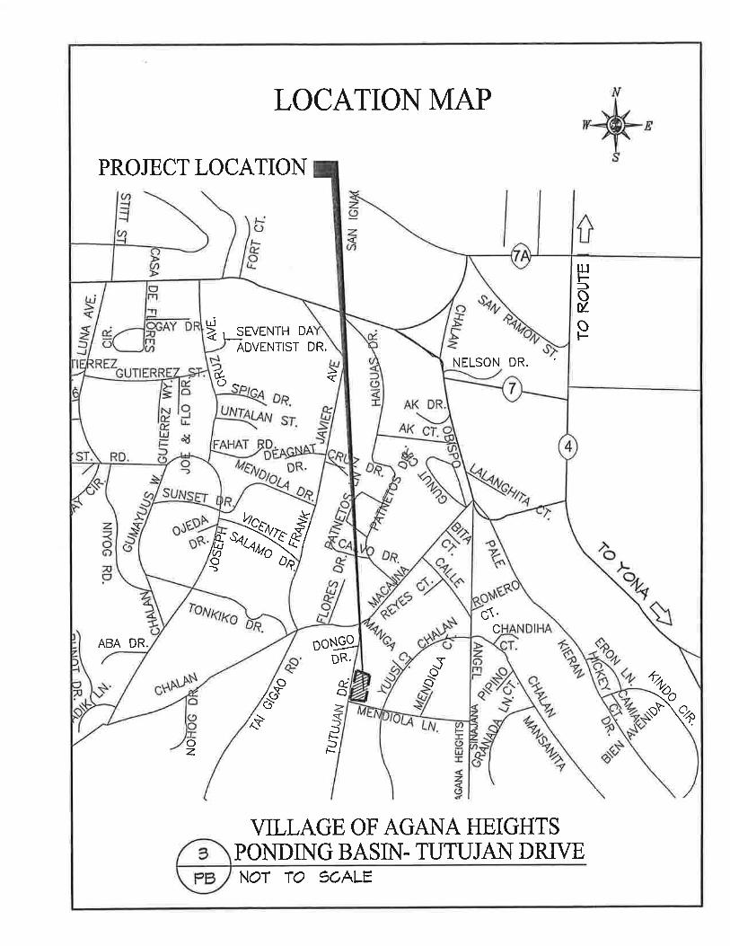
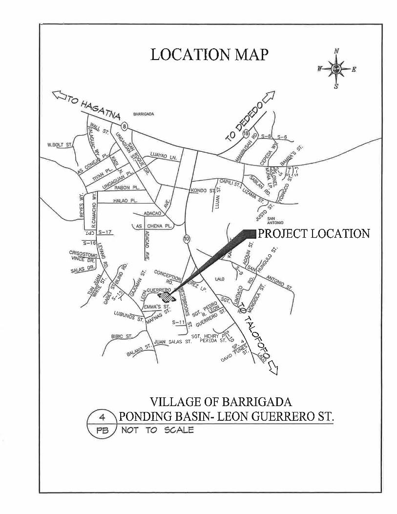
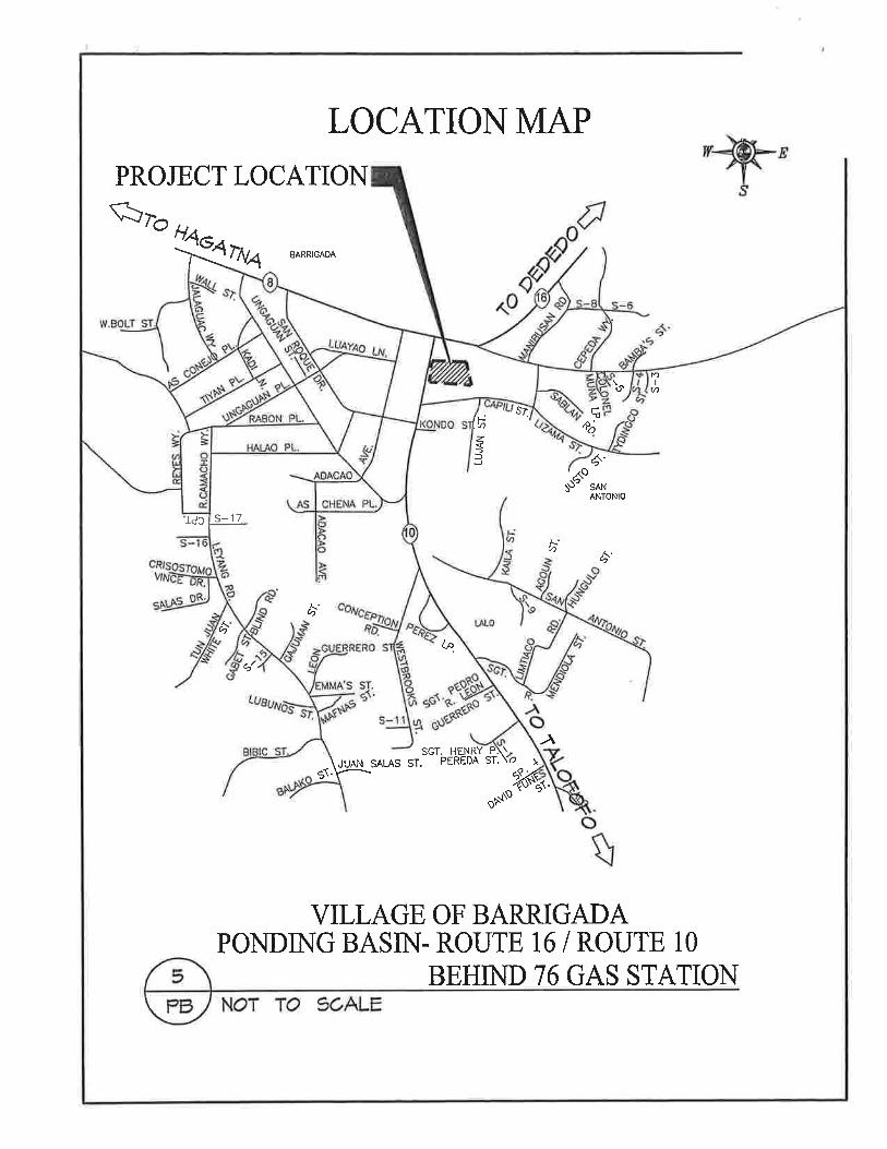
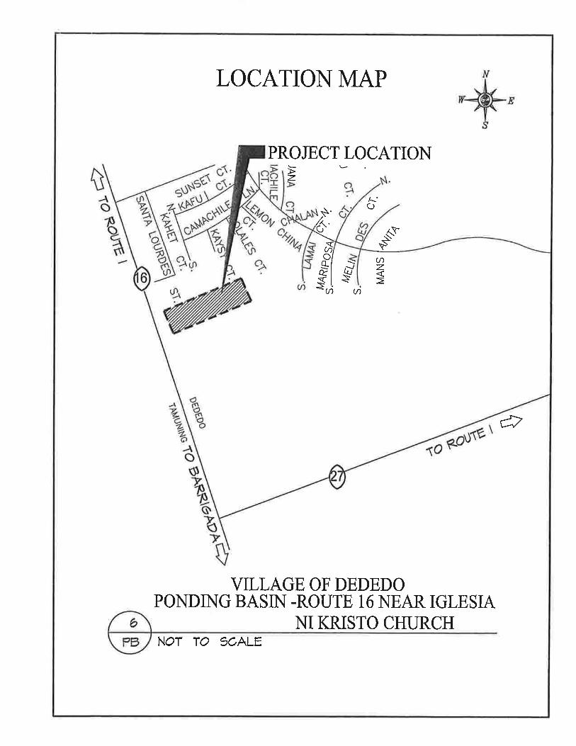


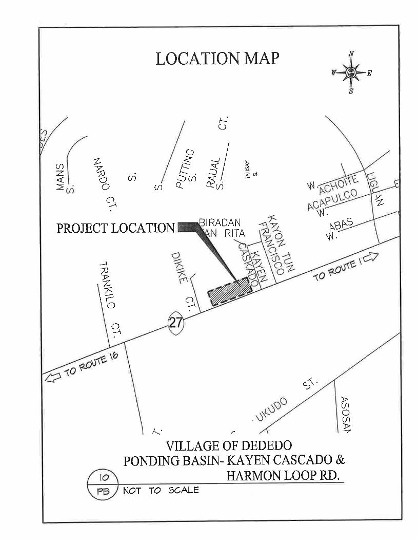
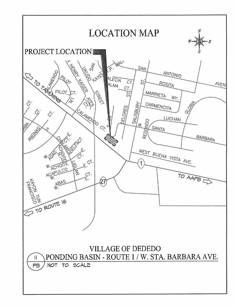

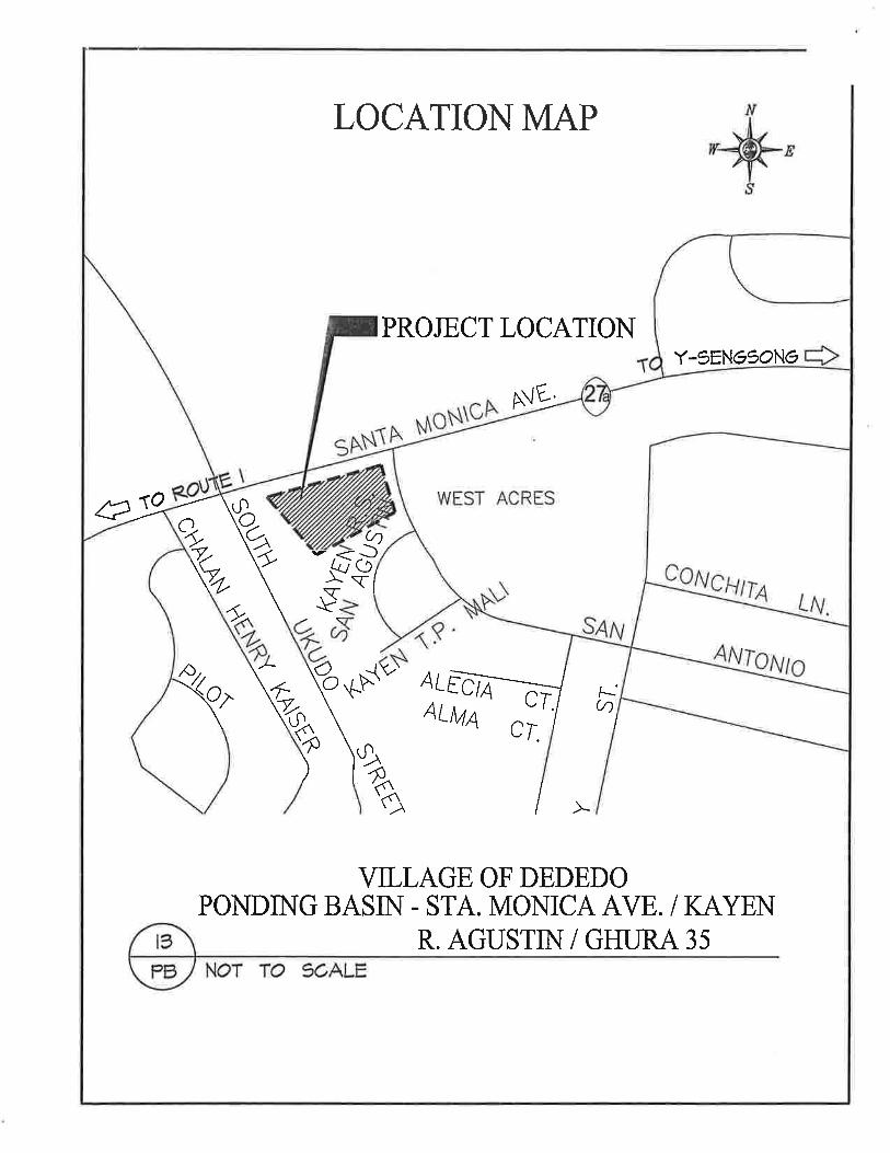
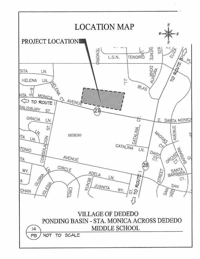


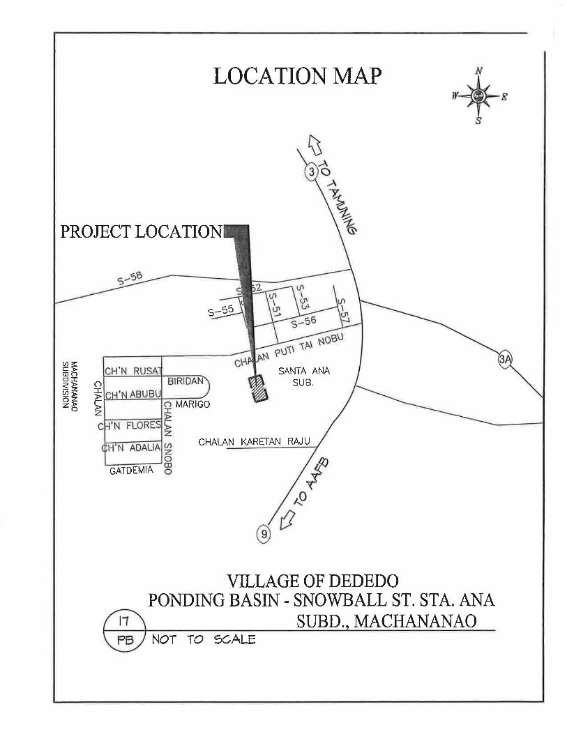
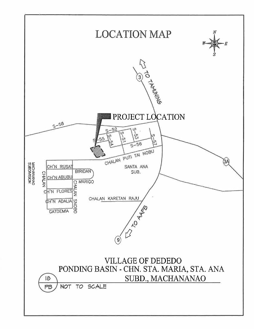

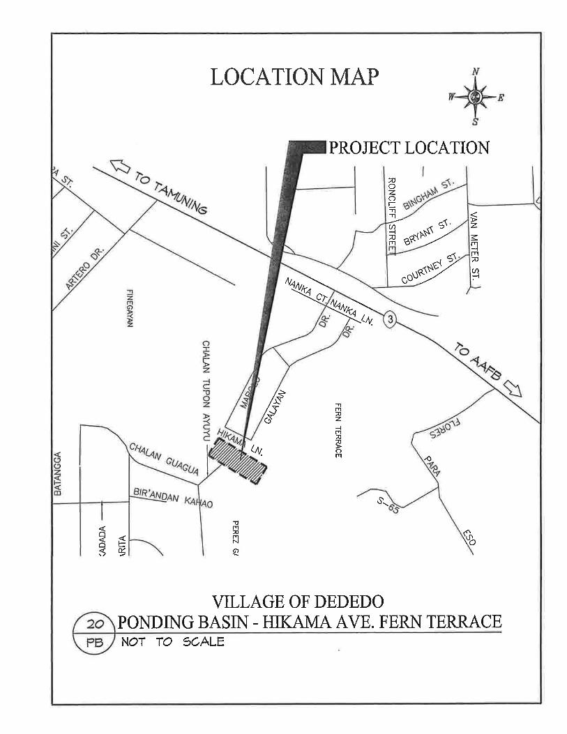


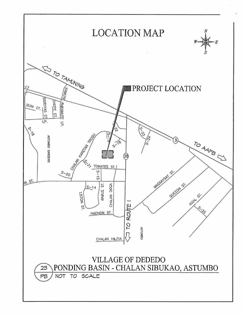

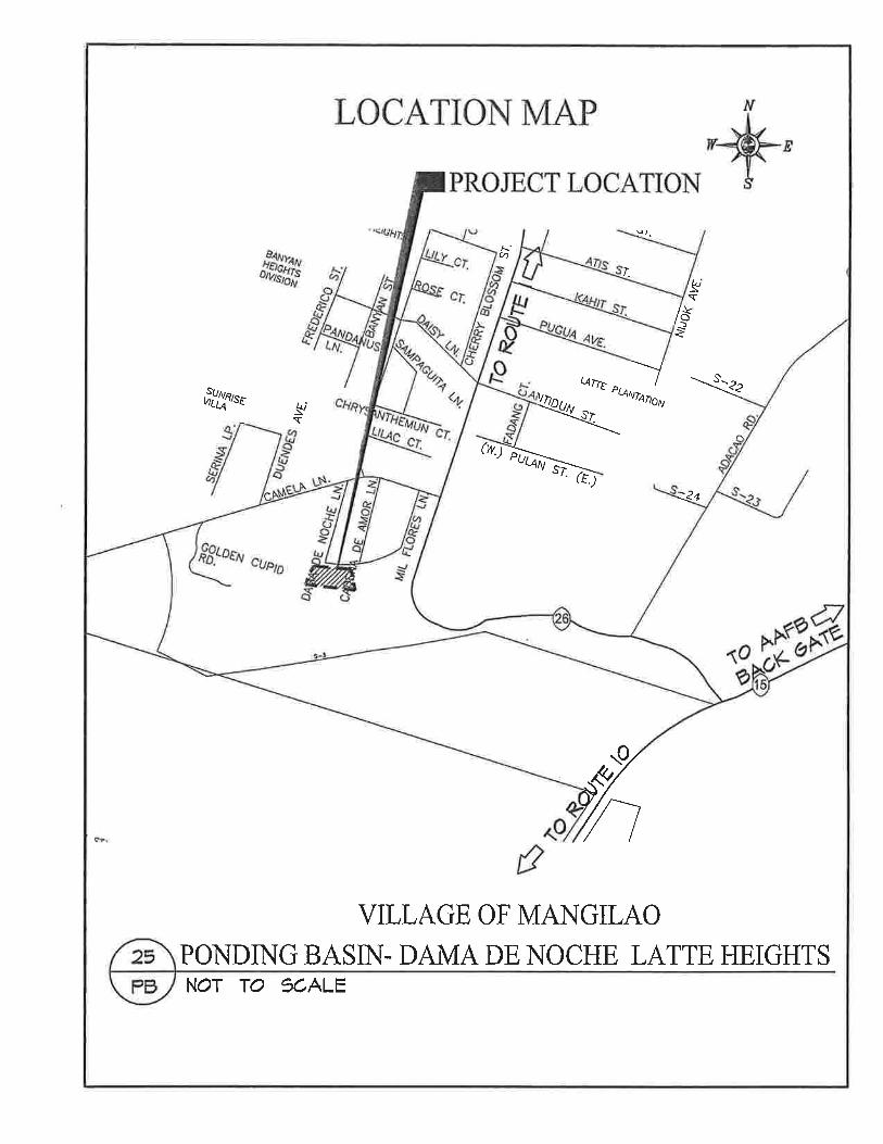
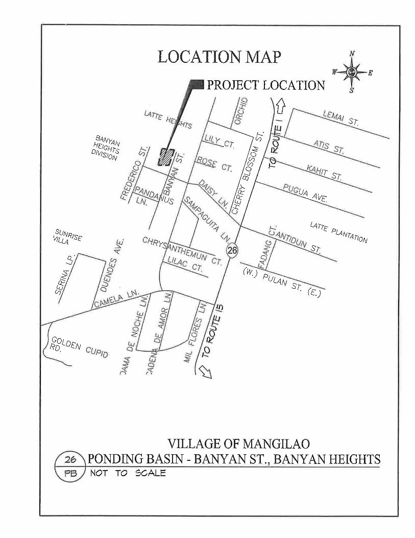

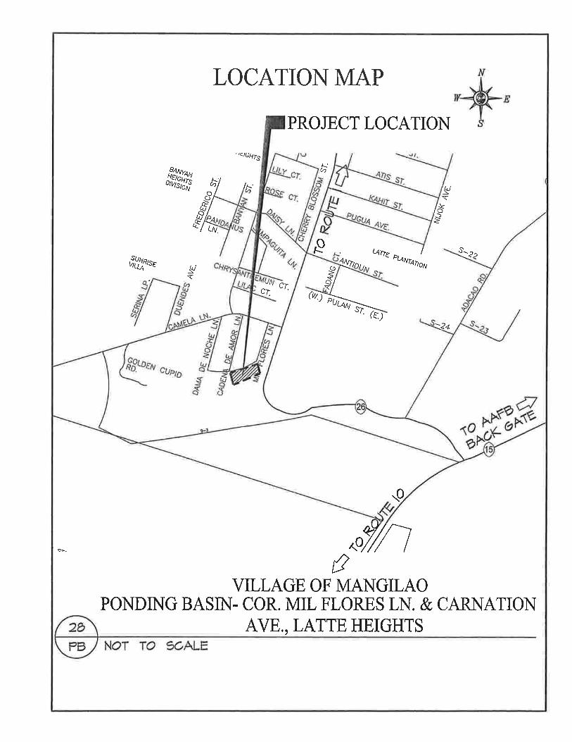
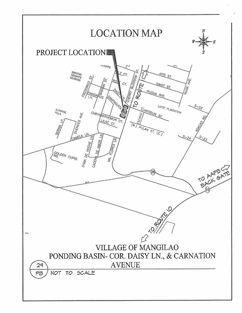
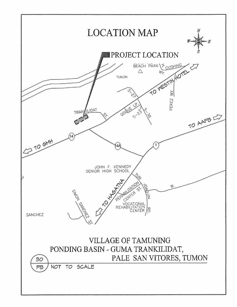
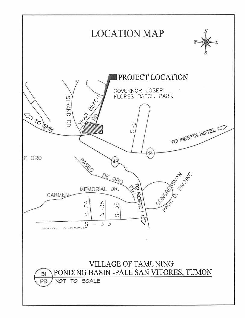

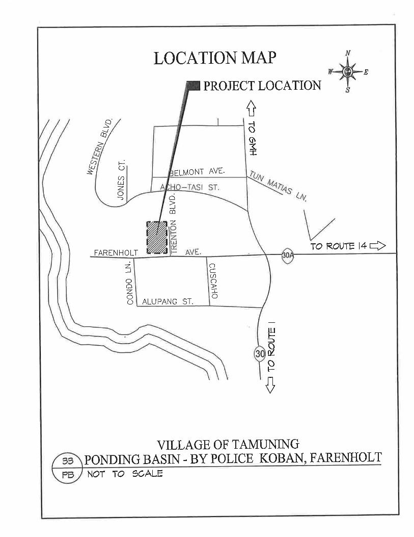
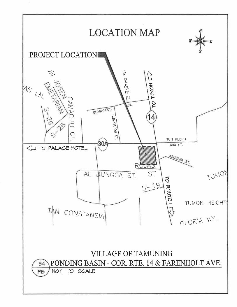


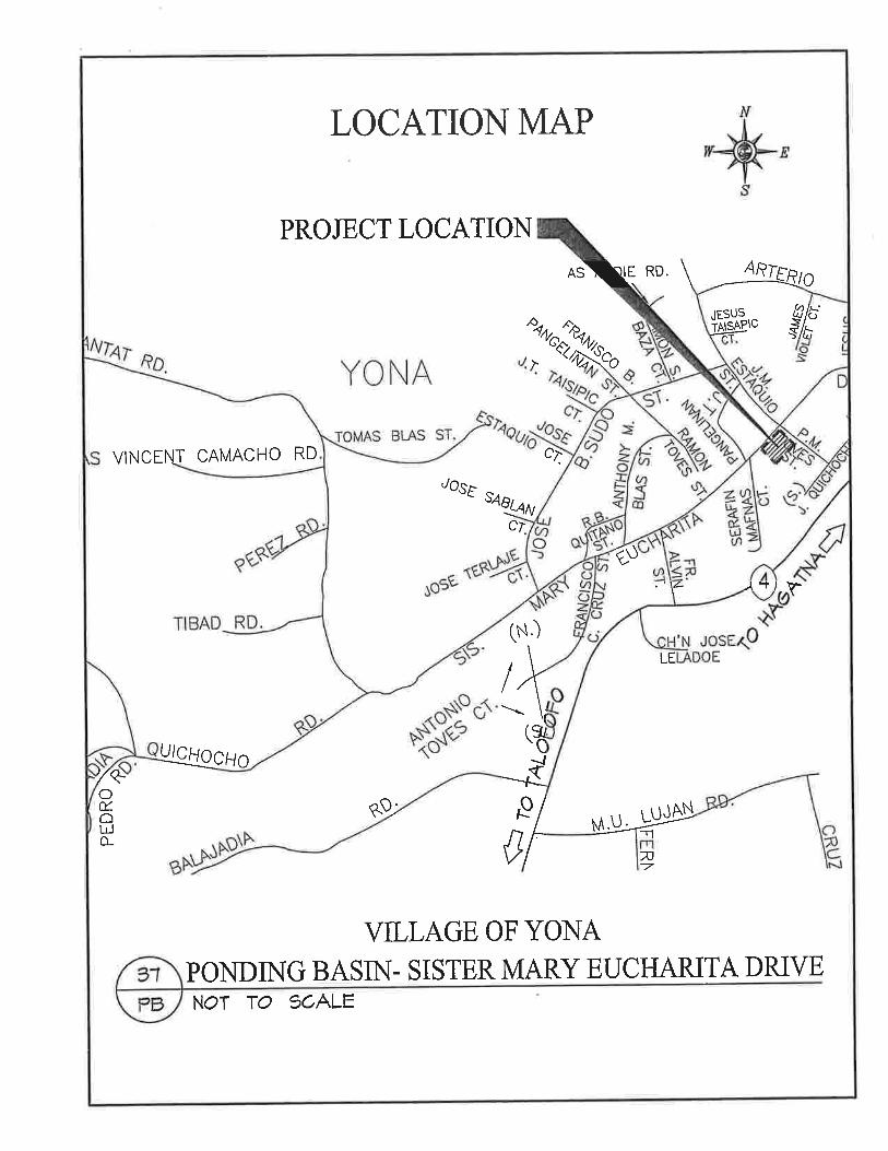
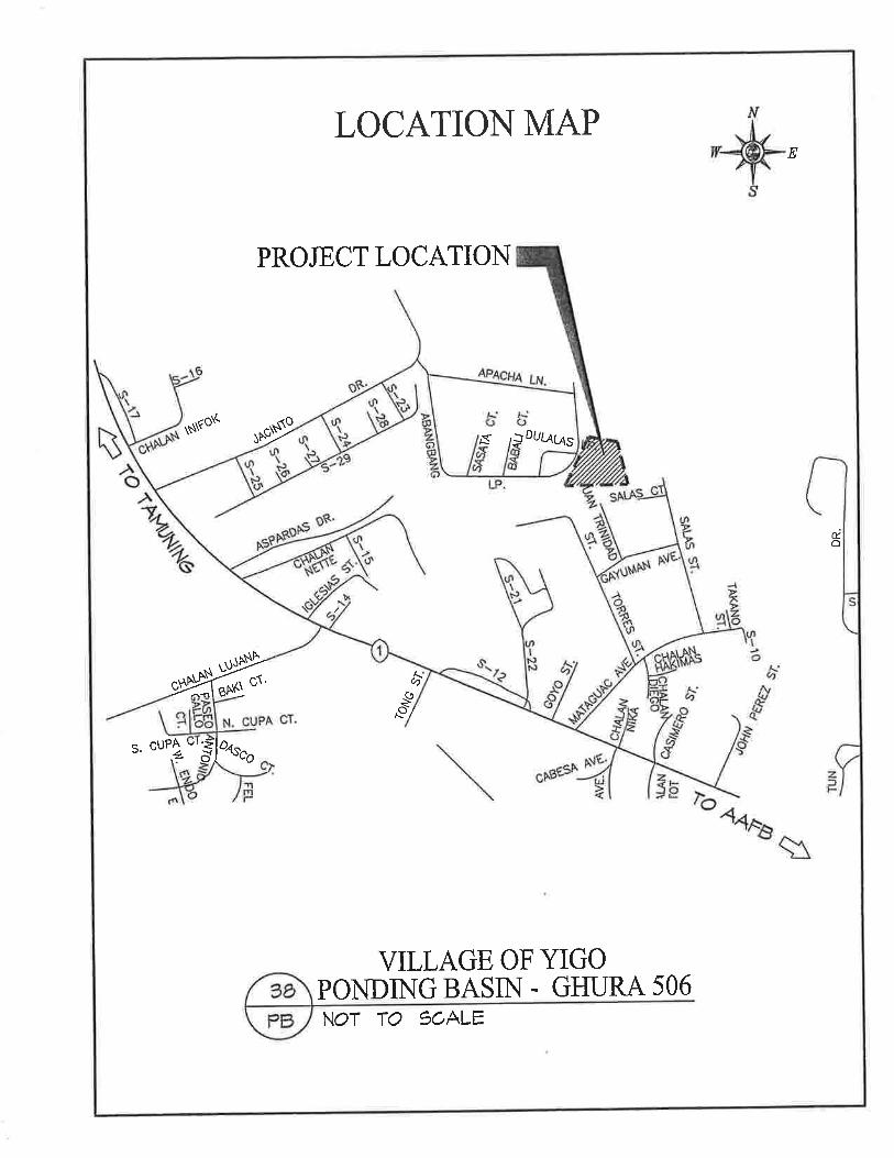
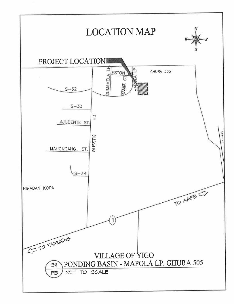
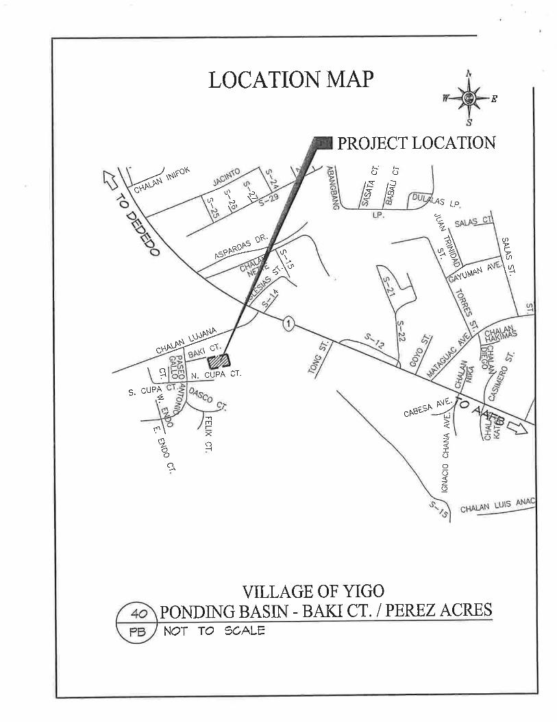

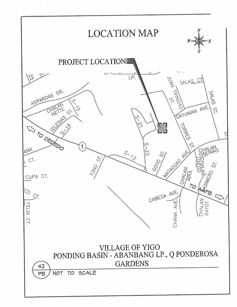


GRN Storm Water Implementation Plan Issue Date: March 2010 Version: Draft Guam DPW Parsons
GUAM_GRN_SW_IMPLEMENTATION_PLAN FINAL_DRAFT_3-15-10.DOC
APPENDIX C GRN OVERVIEW MAP

This page intentionally left blank

GRN Storm Water Implementation Plan Issue Date: March 2010 Version: Draft Guam DPW Parsons
GUAM_GRN_SW_IMPLEMENTATION_PLAN FINAL_DRAFT_3-15-10.DOC B
Guam Road Network
Guam Road Network

This page intentionally left blank
GRN Storm Water Implementation Plan Issue Date: March 2010 Version: Draft Guam DPW Parsons
GUAM_GRN_SW_IMPLEMENTATION_PLAN FINAL_DRAFT_3-15-10.DOC
APPENDIX D FEMA MAPS

This page intentionally left blank

GRN Storm Water Implementation Plan Issue Date: March 2010 Version: Draft Guam DPW Parsons
GUAM_GRN_SW_IMPLEMENTATION_PLAN FINAL_DRAFT_3-15-10.DOC
NORTH GUAM

GRN Storm Water Implementation Plan Issue Date: March 2010 Version: Draft Guam DPW Parsons
GUAM_GRN_SW_IMPLEMENTATION_PLAN FINAL_DRAFT_3-15-10.DOC
SOUTH GUAM ALONG GRN
Agana Bridge @
Rte 1
Fonte Bridge @
Rte 1

GRN Storm Water Implementation Plan Issue Date: March 2010 Version: Draft Guam DPW Parsons
GUAM_GRN_SW_IMPLEMENTATION_PLAN FINAL_DRAFT_3-15-10.DOC
SOUTH GUAM ALONG GRN (CONT’D)
Asan
Bridge 1 @ Rte 1
Masso Bridge @
Rte 1
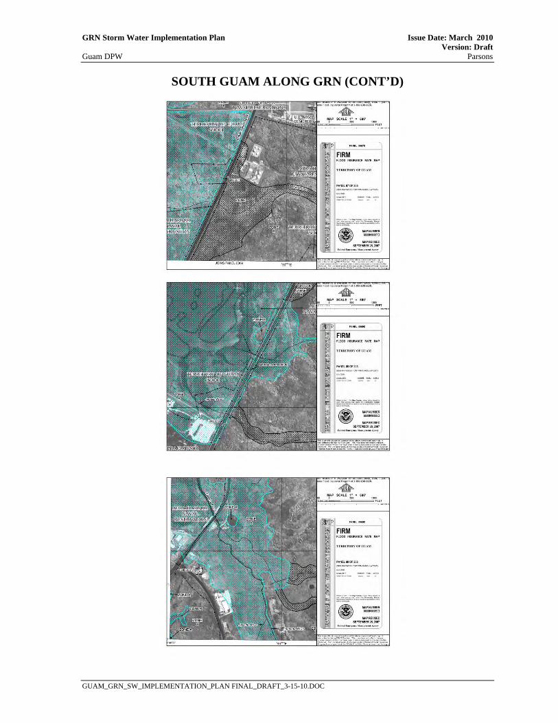
GRN Storm Water Implementation Plan Issue Date: March 2010 Version: Draft Guam DPW Parsons
GUAM_GRN_SW_IMPLEMENTATION_PLAN FINAL_DRAFT_3-15-10.DOC
SOUTH GUAM ALON G GRN (CONT’D)

GRN Storm Water Implementation Plan Issue Date: March 2010 Version: Draft Guam DPW Parsons
GUAM_GRN_SW_IMPLEMENTATION_PLAN FINAL_DRAFT_3-15-10.DOC
APPENDIX E DESIGN GUIDELINES – BIOFILTRATION STRIPS AND SWALES

This page intentionally left blank

GRN Storm Water Implementation Plan Issue Date: March 2010 Version: Draft Guam DPW Parsons
GUAM_GRN_SW_IMPLEMENTATION_PLAN FINAL_DRAFT_3-15-10.DOC
Biofiltration Strips This section provides guidance for incorporating Biofiltration Strip Treatment Best Management Practices (BMPs) into projects during the planning and design phases of transportation related facilities. The primary functions of this document are to:
• Assist with determining the applicability of a Biofiltration Strip (“BioStrip”); • Provide the design guidance; • Cover the required elements for implementing a Biofiltration Strip in a PS&E • package (Plans, Specifications, and Estimates) for a given project; and • Provide information about vegetation for BioStrips.
Biofiltration Strips – A Brief Description Biofiltration Strips are one of several BMPs for treatment of stormwater runoff from project areas that are anticipated to produce pollutants of concern such as roadways or parking lots. BioStrips are sloped vegetated land areas located adjacent to impervious areas, over which storm water runoff flows as sheet flow. Pollutants are removed by filtration through the vegetation, uptake by plant biomass, sedimentation, adsorption to soil particles, and infiltration through the soil. BioStrips are effective at trapping litter, Total Suspended Solids (soil particles), and particulate metals. The following list demonstrates some advantages of utilizing a BioStrip as a Treatment Control BMP.
• When properly implemented, Biostrips are aesthetically pleasing. Due to the presence of its vegetation, the public views Biostrips as a “landscaped roadside” which would make placement more acceptable than other Treatment BMPs using concrete vaults;
• Biostrips were determined to be an effective Treatment BMP in reducing sediment and heavy metals, as described in the BMP Retrofit Pilot Program Final Report (Caltrans, 2004); and
• Biostrips were determined to be cost effective and, together with Bioswales, were among the least expensive Treatment BMP per volume of runoff treated (Caltrans, 2004).
Design Criteria To perform as an effective Treatment BMP, the Biofiltration Strip must meet certain design criteria as follows:
• Side Slope Ratio - Must grade to drain, but no minimum limit (4H:1V or flatter preferred); • Tributary Area – Maximum 150 ft width (length of sheet flow path); • Biofiltration Strip Length (Direction of Flow) - 15 ft minimum; • Manning's n value during WQF - 0.24 (infrequently mowed) recommended; • WQF Velocity - No minimum value, Maximum = 1.0 fps (seldom controls design); • Flow Depth (WQF) - No minimum value, Maximum = 1.0 inch (seldom controls design); and • Vegetative Coverage - 70 % minimum coverage.
Minimum Biofiltration Strip Length Treatment is obtained by BioStrips through filtration through the vegetation, uptake by plant biomass, sedimentation, adsorption to soil particles, and infiltration through the soil. Of these mechanisms, probably the two most important are sedimentation and infiltration. The relative proportion of total treatment done by the sedimentation and infiltration can vary by site, but in terms of total pollutant load reduction (as opposed to concentration reductions) the role played by infiltration can be much more than 50%. Using TSS (total suspended solids) as the key pollutant for this discussion indicated a
GRN Storm Water Implementation Plan Issue Date: March 2010 Version: Draft Guam DPW Parsons
GUAM_GRN_SW_IMPLEMENTATION_PLAN FINAL_DRAFT_3-15-10.DOC
reduction in the TSS concentration of 50% or more can occur after as little as 12 feet of travel for a variety of side slope ratios, including slopes as steep as 2H:1V. The minimum recommended slope length for BioStrips is 15 ft for any side slope ratio as long as the site supports the required 70 percent vegetation coverage without rills or gullies. Site Specific Design Elements Use of Level Spreaders – Due to various difficulties, use of concrete level spreaders is not recommended to distribute runoff. Concentrated runoff at the end of a bridge - Runoff at the end of a bridge will usually be in the form of concentrated flow, rather than sheet flow. Since the use of level spreaders is discouraged, this runoff should be considered for capture in a drainage inlet, from which it ideally would be brought to the base of the embankment and directed into a Biofiltration Swale. The remaining portion of the bridge approach would then be allowed to convey runoff as sheet flow onto BioStrips. Runoff from the end of a bridge should not be allowed to cause erosion. Use of Curbs and Dikes within the roadway cross section - Curbs are used when needed to improve channelization, delineation, or improving traffic flow and safety, and their use will likely not be waived due to water quality issues. However, dikes are used when deemed needed for drainage control, and can be considered in the context both of water quality and highway drainage. Use of dikes should be discouraged as much as possible on embankment sections that would otherwise meet BioStrip criteria. Design Drawings Layout Sheets - Show location(s) of BioStrips. This will aid in the recognition within and outside the Department that BioStrips were placed within the project limits. Contour Grading Sheets - As BioStrips are primarily earthwork features they may be shown on Contour Grading sheets. Any other associated grading surrounding the BioStrip should be shown on these sheet(s). Construction Details - There will not typically be any construction details associated with BioStrips, but if there are, these sheets may be used to show these items. Landscape Plans - These sheets, and the Contour Grading sheets, will be the primary sheets used to show the placement of the landscape contract items of work for BioStrips. Other Sheets - Drainage Plans, Water Pollution Control, Erosion Control Plans, Construction Staging, Utility Plans, Irrigation Plans, and other sheets should be considered as appropriate for the construction of BioStrips on a project-specific basis. If BioStrips will be constructed at multiple locations, a “Locations of Construction” table should be considered. This table could present the stationing and other location information. WQF could also be considered. This table may be incorporated into an existing drawing if there is room (such as a Title, Layout or Construction Detail), or may be developed as a separate drawing if necessary. Soil and Planting Bed Preparation The soils in areas designated for biofiltration should be ripped and cultivated to a minimum depth of 12-inches to relieve surface compaction. Compost should be incorporated at a minimum rate of 400 cu yd/acre (3-inch layer) to a minimum depth of 12-inches in all areas designated for biofiltration to restore soil organics, rooting depth, porosity and nutrients (carbon and nitrogen). Compost incorporation is typically recommended for slopes less than or equal to 4:1 H:V. Compost incorporation is not suggested for areas where harvested topsoil will be placed. Designate topsoil harvest and stockpile locations on the plans. Include details for re-application and placement of topsoil.

GRN Storm Water Implementation Plan Issue Date: March 2010 Version: Draft Guam DPW Parsons
GUAM_GRN_SW_IMPLEMENTATION_PLAN FINAL_DRAFT_3-15-10.DOC
Planting Strategies The following criteria should be used as a general measure of successful Biofiltration BMP installation:
• Within the first year, a minimum of 70 percent vegetative cover is achieved. • Within three years, 75 to 85 percent vegetative cover is achieved. • The Biofiltration BMP does not exhibit rills, gullies, or visible erosion that is contributing to
the export of sediment. • Temporary cover with sufficient longevity should be provided until the desired percentage
cover of vegetation is achieved. • Temporary cover is usually provided through the use of short-term, degradable erosion
control products such as rolled erosion control products (RECPs), wood chips and compost, straw, and hydromulch. These products vary in how long they will last. For example, straw can be expected to last through a single rainy season while a woven coconut fiber netting will usually persist for 3 years.
• Strive for cost effective solutions. In most cases, the temporary cover product with the greatest longevity will also be the most expensive. While plant performance, slope steepness, slope inclination, slope aspect, and soil characteristics must be considered, avoid over-design. Specify different materials when warranted by diverse project conditions. For example, a cost-effective project design may include the use of blown straw and hydroseed on areas of good soil and gentle slopes whereas compost and coir netting are reserved for steep, cut slopes.
• Combine hydroseeding and direct planting. Some plant species favor particular planting methods, so allowances have to be made if these species are to be used. Many plant species can be applied by hydroseeding. Other plants are better established as liner, container, or plug plant material and can be installed in previously seeded areas, following germination. This method can be effective for bioswales when the upland zone on the banks is hydroseeded and the hydrophilic zone in the bed is planted with sedge, grass, and rush liners.
• Specify pre-germination or include mulch for weed control. Pre-germination is a very effective method for killing weeds that germinate from an existing seed bank. Planting by hydroseeding or other methods should be done after one or more pregermination cycles.
• Specify erosion control blankets or other RECPs in areas that will receive concentrated flow. Although hydroseeding may be appropriate for planting portions of bioswales, it should not be used in locations that will receive concentrated runoff. Liner, container or plug plant material is a better choice in these areas.
• Specify “stepped-slope” construction for grading cut slopes. Cut slopes are difficult to vegetate for different reasons such as rocky subsoil, compaction, removal of topsoil and organic material, and steepness. Using a “stepped-slope” method can enhance vegetation establishment. This method involves making a series of cuts, or small benches, starting at the top of the proposed cut slope and working down. The final slope has a “stair step” appearance rather than a smooth, scraped slope. Each step should be between 2 to 6 feet wide. By allowing approximately 50 percent of the loose, excavated material to remain on each step, a planting bed is created. This planting be can be further enhanced by adding compost.

GRN Storm Water Implementation Plan Issue Date: March 2010 Version: Draft Guam DPW Parsons
GUAM_GRN_SW_IMPLEMENTATION_PLAN FINAL_DRAFT_3-15-10.DOC
Restrictions for Plant Selection Nearly half of the bulk solids collected in the structural treatment BMPs consists of plant litter such as leaves and twigs. To maintain the efficiency of these BMPs trees and large shrubs selected for banks of biofiltration swales should contribute minimal plant litter to the BMP. Deciduous trees and other species that contribute large amounts of bark, leaf, flower, or seed litter should be avoided. Plant Establishment Period (PEP) PEP ensures project success by maintaining plants during a period when mortality rates tend to be high. This is true for Highway Planting, as well as for revegetation planting that includes grasses and forbs, and especially native grasses. The following should be considered when requiring PEP for biofiltration BMPs:
• Biofiltration BMPs that are graded, constructed and planted as part of a roadway construction contract should have a 1-year PEP. Depending upon the type of construction and order of work, the PEP may run concurrently with other work.
• Work to be performed during the PEP should include the following when applicable for the project: a) Weed control and removal of inappropriate plant species, b) Mowing and other vegetation management, c) Repair of rills, gullies, and other damage caused by erosion and scour, d) Reseeding of bare or repaired areas, g) Removal of accumulated sediment and debris.
• Ideally, a 3-year contract to perform plant establishment work should follow immediately after completion of the roadway contract that installed the Biofiltration BMPs. If practical, the follow-up contract may include the Biofiltration BMPs of several construction projects in proximity of each other.

GRN Storm Water Implementation Plan Issue Date: March 2010 Version: Draft Guam DPW Parsons
GUAM_GRN_SW_IMPLEMENTATION_PLAN FINAL_DRAFT_3-15-10.DOC
Biofiltration Swales
This document provides guidance for incorporating Biofiltration Swale Treatment Best Management Practices (BMPs) into projects during the planning and design phases of transportation facilities. The primary functions of this document are to:
• Describe the design criteria of Biofiltration Swales (“Bioswales”); • Present detailing standards and siting limitations; • Present the formulas used to design Bioswales; and • Review the required elements for implementing Bioswales into PS&E packages.
Biofiltration Swales – A Brief Description Biofiltration Swales are one of several BMPs for treatment of stormwater runoff from project areas that are anticipated to produce pollutants of concern (e.g., roadways, parking lots). Bioswales are vegetated, typically trapezoidal channels, which receive and convey storm water flows while meeting water quality criteria and other flow criteria. Pollutants are removed by filtration through the vegetation, uptake by plant biomass, sedimentation, adsorption to soil particles, and infiltration through the soil. Pollutant removal capability is related to channel dimensions, longitudinal slope, and type of vegetation. Bioswales are effective at trapping litter, Total Suspended Solids (soil particles), and particulate metals (Caltrans, 2007). The following list demonstrates some advantages of utilizing a Bioswale as a Treatment Control BMP.
• When properly implemented, Bioswales are aesthetically pleasing. Due to the presence of its vegetation, the public views Bioswales as a “landscaped roadside” which would make placement more acceptable than other Treatment BMPs using concrete vaults.
• Bioswales were determined to be an effective Treatment BMP in reducing sediment and heavy metals, as described in the BMP Retrofit Pilot Program Final Report (Caltrans, 2004).
• In that same report, Bioswales were determined to be cost effective and, together with Biofiltration Strips, were among the least expensive Treatment BMP per volume of runoff treated.
Design Criteria To perform as an effective Treatment BMP, the Biofiltration Swale must meet certain design criteria; the primary factors to be incorporated into the design are found in the table below.
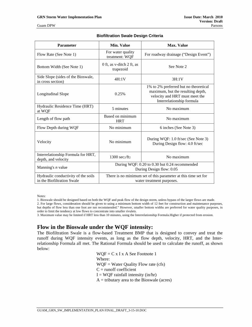
GRN Storm Water Implementation Plan Issue Date: March 2010 Version: Draft Guam DPW Parsons
GUAM_GRN_SW_IMPLEMENTATION_PLAN FINAL_DRAFT_3-15-10.DOC
Biofiltration Swale Design Criteria
Notes: 1. Bioswale should be designed based on both the WQF and peak flow of the design storm, unless bypass of the larger flows are made. 2. For large flows, consideration should be given to using a minimum bottom width of 12 feet for construction and maintenance purposes, but depths of flow less than one foot are not recommended.” However, smaller bottom widths are preferred for water quality purposes, in order to limit the tendency at low flows to concentrate into smaller rivulets. 3. Maximum value may be limited if HRT less than 10 minutes, using the Interrelationship Formula.Higher if protected from erosion.
Flow in the Bioswale under the WQF intensity: The Biofiltration Swale is a flow-based Treatment BMP that is designed to convey and treat the runoff during WQF intensity events, as long as the flow depth, velocity, HRT, and the Inter-relationship Formula all met. The Rational Formula should be used to calculate the runoff, as shown below:
WQF = C x I x A See Footnote 1 Where: WQF = Water Quality Flow rate (cfs) C = runoff coefficient I = WQF rainfall intensity (in/hr) A = tributary area to the Bioswale (acres)
Parameter Min. Value Max. Value
Flow Rate (See Note 1) For water quality treatment: WQF For roadway drainage (“Design Event”)
Bottom Width (See Note 1) 0 ft, as v-ditch 2 ft, as trapezoid
See Note 2
Side Slope (sides of the Bioswale, in cross section) 4H:1V 3H:1V
Longitudinal Slope 0.25%
1% to 2% preferred but no theoretical maximum, but the resulting depth, velocity and HRT must meet the
Interrelationship formula Hydraulic Residence Time (HRT) at WQF 5 minutes No maximum
Length of flow path Based on minimum HRT No maximum
Flow Depth during WQF No minimum 6 inches (See Note 3)
Velocity No minimum
During WQF: 1.0 ft/sec (See Note 3)
During Design flow: 4.0 ft/sec
Interrelationship Formula for HRT, depth, and velocity 1300 sec2/ft2 No maximum
Manning's n value During WQF: 0.20 to 0.30 but 0.24 recommended
During Design flow: 0.05 Hydraulic conductivity of the soils in the Biofiltration Swale
There is no minimum set of this parameter at this time set for water treatment purposes.

GRN Storm Water Implementation Plan Issue Date: March 2010 Version: Draft Guam DPW Parsons
GUAM_GRN_SW_IMPLEMENTATION_PLAN FINAL_DRAFT_3-15-10.DOC
Flow in the Bioswale during the Design Event: The Bioswale must be designed to convey larger during rainfall intensities greater than the WQF, and in fact must handle the peak drainage from the roadway unless an upstream bypass for the larger events is provided. Absent such diversion, the “Design Event” for the Bioswale must be consistent with the intensity, duration and frequency of the rainfall event used in the roadway drainage design for that tributary area contributing runoff to the Treatment BMP. Flow depths and velocities at WQF and during Design Event The flow depth during WQF and the Design Event can be calculated using Manning’s Equation, as shown below.
Q = (1.486/n) x A x R2/3 x S1/2 Where Q = flow at defined event (WQF or Q25) n = Manning’s coefficient; recommend using “n” = 0.24 for WQF and 0.05 for the Design Event Q25 A = Cross-sectional area of the flow in the channel R = Hydraulic Radius = “A” / Wetted Perimeter (“P”) S = longitudinal slope
Hydraulic Residence Time There is a minimum travel time within the Bioswale, termed the Hydraulic Residence Time [HRT]) set at 5 minutes. This can be checked after the proposed Bioswale site is analyzed using Manning’s Equation, as discussion above. After the velocity associated with the WQF is determined, the HRT is calculated using the proposed length of the Bioswale:
HRT = L / (60 x VWQF) where L = proposed length of the Bioswale (ft) HRT = Hydraulic Residence Time (minutes) VWQF = velocity at WQF (ft/sec) 60 = conversion from seconds to minutes
A minimum Hydraulic Residence Time of 5 minutes has been assigned to Bioswales. If the HRT is less than 5 minutes, then the length of the Bioswale should be increased, or the velocity at the WQF should be decreased by increasing the width of the Bioswale or by decreasing the slope. Interrelationship Formula during WQF Upon determining that the HRT, dWQF, and VWQF meet their respective design criteria, the Interrelationship Formula shown below also must be satisfied, as the maximum allowed depth of flow and velocity may be restricted if the HRT is less than 10 minutes.
(HRT x 60)/(dWQF x VWQF ) >= C where: HRT = Hydraulic Residence Time during WQF 60 = conversion factor from minutes to seconds dWQF = depth of flow at WQF (ft) VWQF = velocity of flow at WQF (fps) C = constant: 1,300 (sec2/ft2)

GRN Storm Water Implementation Plan Issue Date: March 2010 Version: Draft Guam DPW Parsons
GUAM_GRN_SW_IMPLEMENTATION_PLAN FINAL_DRAFT_3-15-10.DOC
Other Comments • The Bioswale should be designed with the maximum length (in direction of flow) as allowed
by the site. In general, the flatter the slope, the shorter the Bioswale length required to meet Treatment BMP requirements.
• The width of the Bioswale is often the most easily changed site variable if the original proposed dimensions do not satisfy depth, velocity and Hydraulic Residence Time (HRT) criteria at WQF, but sometimes the slope may be reduced.
• The tributary area upstream of Bioswales is usually not as large as the tributary areas for volume-based Treatment BMPs.
• Calculations for the Bioswale, especially the HRT, are easier if most or all of the WQF enters at a discrete location at the upstream, rather than at distributed locations along the length of the Bioswale. However, if the flow enters the Biofiltration Swale continuously along the length of the swale or at multiple discrete locations, other rational methods should be employed; for example: the analysis could calculate the depths and velocities at selected points along the Bioswale, using the Q at that location, with the remaining downstream length of the Bioswale, to verify that all criteria have been met.
• Use of check dams within the Bioswale: If the HRT, velocity, or length requirements are not met (and they are all interrelated) due to the steepness of the proposed Bioswale, but the HDM criteria are met, the use of check dams within the Bioswale can be considered and the check dam should be constructed of soil, placed a maximum of 20 ft apart, using 4H:1V slopes, maximum height of 9 inches, placement should not impede the flow of the Design Event and should be vegetated.
Location Biofiltration Swales, and the related Biofiltration Strips, are probably the least expensive Treatment BMPs for an area, if the proposed location is otherwise suitable. However, to provide effective treatment of runoff, the proposed location must be able to support the chosen vegetation; locations should be sought that have sufficient open space, adequate sunlight for vegetation growth, and topography to meet the hydraulic requirements. Entry of runoff into a Bioswale may enter as sheet flow along its length, and/or from a concentrated conveyance. If the latter, it may require energy dissipation to prevent erosion. One location that should receive special consideration is at the end of a bridge structure. Erosion Control When the flow velocity exceeds 4 ft/sec for the largest design storm, a geotextile, such as turf reinforcement mat (TRM), may be used to prevent scour within the swale. The use of a TRM within the swale for velocities higher than 4 ft/sec during design storm events does not negate the need to meet all the design criteria during Water Quality events. If the flow characteristics do not require a TRM, a temporary erosion control blanket or RECP (Rolled Erosion Control Product) may still be needed to protect the soil from concentrated flow that may occur the first winter before vegetation can be established. For example, hydroseeding is not recommended for areas that will receive concentrated flows. The runoff entering at the upstream end of the Bioswale, if entering as concentrated flow from a drainage conveyance (e.g., from a lined channel or at the end of a bridge), should not cause erosion, and detailing such as flared end sections should be considered. Design Drawings Layout Sheets - Show location(s) of Bioswales. This will aid in the recognition within and outside the Department that Bioswales were placed within the project limits.

GRN Storm Water Implementation Plan Issue Date: March 2010 Version: Draft Guam DPW Parsons
GUAM_GRN_SW_IMPLEMENTATION_PLAN FINAL_DRAFT_3-15-10.DOC
Contour Grading Sheets - As Bioswales are primarily earthwork features they may be shown on Contour Grading sheets. Any other associated grading surrounding the Bioswale should be shown on these sheet(s). Construction Details - There will not typically be any construction details associated with Bioswales, but if there are, these sheets may be used to show these items. Landscape Plans - These sheets, and the Contour Grading sheets, will be the primary sheets used to show the placement of the landscape contract items of work for Bioswales. Other Sheets - Drainage Plans, Water Pollution Control, Erosion Control Plans, Construction Staging, Utility Plans, Irrigation Plans, and other sheets should be considered as appropriate for the construction of Bioswales on a project-specific basis. If Bioswales will be constructed at multiple locations, a “Locations of Construction” table should be considered. This table could present the stationing and other location information. WQF could also be considered. This table may be incorporated into an existing drawing if there is room (such as a Title, Layout or Construction Detail), or may be developed as a separate drawing if necessary. Soil and Planting Bed Preparation See Biostrip Section Planting Strategies See Biostrip Section Restrictions for Plant Selection See Biostrip Section Plant Establishment Period (PEP) See Biostrip Section

This page intentionally left blank

GRN Storm Water Implementation Plan Issue Date: March 2010 Version: Draft Guam DPW Parsons
GUAM_GRN_SW_IMPLEMENTATION_PLAN FINAL_DRAFT_3-15-10.DOC
APPENDIX F BRIDGE REPLACEMENT PROJECT DATA

This page intentionally left blank

GRN Storm Water Implementation Plan Issue Date: March 2010 Version: Draft Guam DPW Parsons
GUAM_GRN_SW_IMPLEMENTATION_PLAN FINAL_DRAFT_3-15-10.DOC
Several of the Route 1 bridge crossings will be replaced as part of the GRN project. These include bridges over the Agana River, the Fonte River, the Laguas River, the Agueda River and the Atantano Bridge. On-site and off-site design requirements for these bridges are described in Section 7.2. Additional information for these offsite channels is provided below.
• Agana Bridge - This concrete structure spans 42 ft over the Agana (Hagatna) River for a length of 87 ft under Route 1 and shows signs of decay through severe cracking, delamination and spalling of concrete. Erosion along the abutments was apparent on the upstream side of the bridge (see Figure F-1).
• Fonte Bridge - This five span, concrete frame structure spans 78 ft over the Fonte River for a length of 100 ft under Route 1. Hairline vertical cracks are located on the pier walls with some delamination, spalling and exposed rebar shown in some of the piers on the downstream side.
• Laguas Bridge - This single span box girder bridge spans 46 ft over Laguas River for a length of 81 ft under Route 1. The bridge exhibits moderate cracking and spalling in the beams and scour in the north abutment. The bottom of the channel upstream of the bridge had been removed of vegetation, increasing erosion potential along the channel bottom (see Figure F-2).
• Agueda Bridge - This 3-barrel concrete box culvert spans 27 ft over the Agueda River for a length of 81 ft under Route 1. Downstream obstructions have produced backwater effects upstream of the culvert (see Figure F-3), since at the time of inspection, the culvert openings were inundated. Erosion was apparent at the upstream wingwalls.
Figure F-2 Laguas Bridge Upstream Section
Figure F-3 Agueda Bridge Downstream Obstructions
Figure F-1 Agana Bridge Upstream Embankment
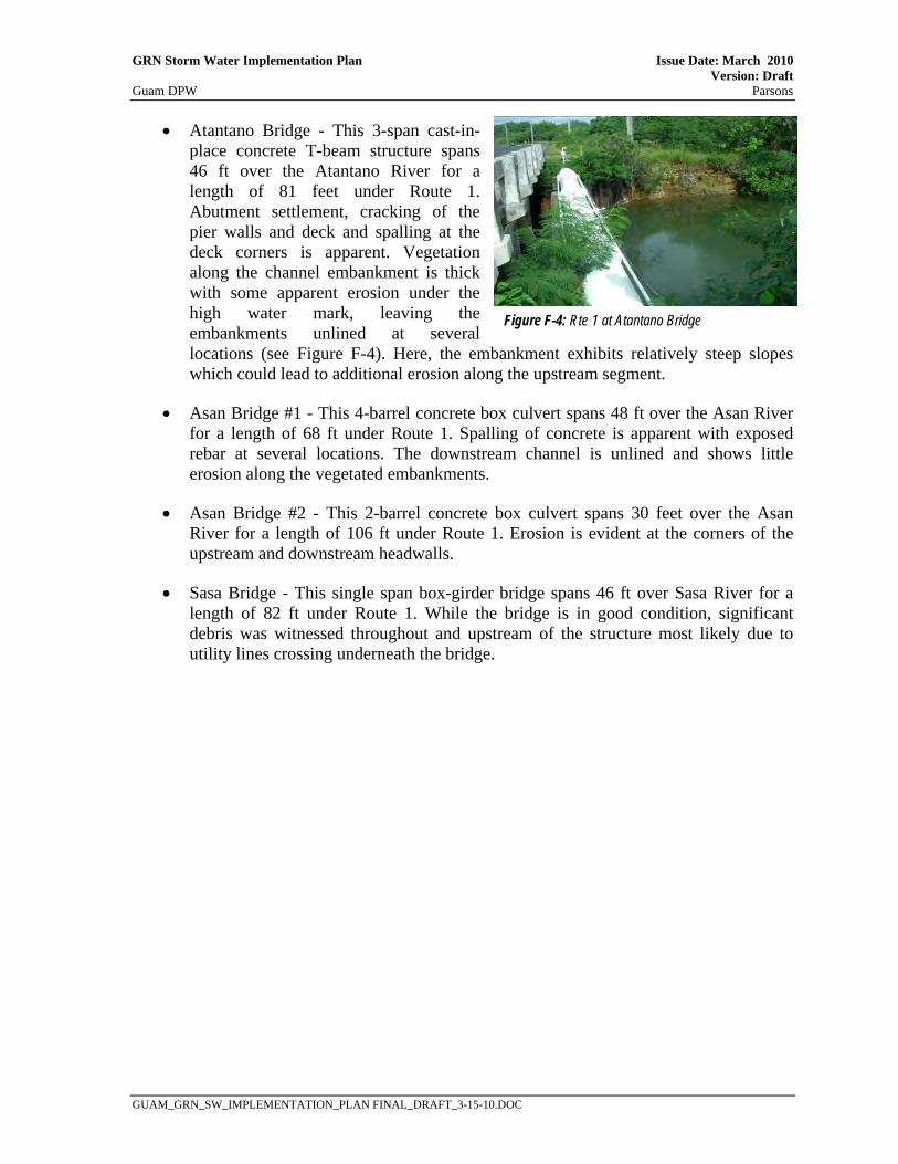
GRN Storm Water Implementation Plan Issue Date: March 2010 Version: Draft Guam DPW Parsons
GUAM_GRN_SW_IMPLEMENTATION_PLAN FINAL_DRAFT_3-15-10.DOC
• Atantano Bridge - This 3-span cast-in-place concrete T-beam structure spans 46 ft over the Atantano River for a length of 81 feet under Route 1. Abutment settlement, cracking of the pier walls and deck and spalling at the deck corners is apparent. Vegetation along the channel embankment is thick with some apparent erosion under the high water mark, leaving the embankments unlined at several locations (see Figure F-4). Here, the embankment exhibits relatively steep slopes which could lead to additional erosion along the upstream segment.
• Asan Bridge #1 - This 4-barrel concrete box culvert spans 48 ft over the Asan River for a length of 68 ft under Route 1. Spalling of concrete is apparent with exposed rebar at several locations. The downstream channel is unlined and shows little erosion along the vegetated embankments.
• Asan Bridge #2 - This 2-barrel concrete box culvert spans 30 feet over the Asan River for a length of 106 ft under Route 1. Erosion is evident at the corners of the upstream and downstream headwalls.
• Sasa Bridge - This single span box-girder bridge spans 46 ft over Sasa River for a length of 82 ft under Route 1. While the bridge is in good condition, significant debris was witnessed throughout and upstream of the structure most likely due to utility lines crossing underneath the bridge.
Figure F-4: Rte 1 at Atantano Bridge