guardian ii pipeline washer guardian ii - milking parlors ... · guardian ii pipeline washer 3...
TRANSCRIPT

Guardian II Pipeline Washer 1 9ES-680A
English —————— v —————— Español
Guardian II Pipeline WasherInstallation, Operation & Maintenance Instructions
Bou-Matic LLCPO Box 8050 • Madison, WI USA 53708 • Telephone (608) 222-3484 • Fax: (608) 222-9314
Guardian II Limpiador de tuberías
Instrucciones de instalación, operación ymantenimiento
ContentsIntroduction ...................................................................................................... 21. Preparation .................................................................................................. 3
1.1 Verifying Part and Tool Requirements ................................................. 31.2 Reviewing Personal Safety Instructions .............................................. 41.3 Reviewing Installation Specifications ................................................... 5
2. Installation .................................................................................................... 52.1 Installing the Electrical & Pump Modules ............................................. 62.2 Installing Accessories .......................................................................... 7
Temperature Sensor ......................................................................... 7Water Solenoid Valves ...................................................................... 8Diverter Valve .................................................................................... 9Drain Valve ........................................................................................ 9Milkline Position Switch—option ........................................................ 9Printer or Personal Computer—option ............................................. 10
2.3 Installing Auxiliary Products ............................................................... 112.4 Wiring the Controls ............................................................................ 152.5 Connecting Hoses ............................................................................. 18
3. System Programming ................................................................................. 203.1 Understanding Basic Data Entry Functions ....................................... 203.2 Initializing the System ........................................................................ 20
Start-up and Setup Data Entry ........................................................ 20Error Messages ............................................................................... 22
3.3 Fine Tuning Cycle Settings ................................................................ 233.4 Calibrating the Chemical Pumps ........................................................ 263.5 Calibrating the Temperature Sensor .................................................. 273.6 Setting Auxiliary Output Variables ..................................................... 28
Auxiliary Outputs ............................................................................. 28Plate Cooler Cold and Plate Cooler Hot .......................................... 28
3.7 Entering System Setup Data ............................................................. 29Baud Rate ....................................................................................... 29Dairy Name ..................................................................................... 29Display Intensity .............................................................................. 30Print the Parameters ....................................................................... 31
3.8 Entering Control Variables ................................................................. 31Sink Capacity .................................................................................. 32Fill Time Limit .................................................................................. 32Fill Temperature Stability ................................................................. 32Pump Delays ................................................................................... 33Print Frequency ............................................................................... 33
3.9 Setting the Phase Variables .............................................................. 33Chemical Amounts .......................................................................... 34Extra Chemical ................................................................................ 35Fill Temperature .............................................................................. 36Fill Alarm Temperature .................................................................... 36Cycle Times .................................................................................... 37Circulation Stop Temperature .......................................................... 34Diverter Delay Time ........................................................................ 38Sanitize Start Times ........................................................................ 38Extra Water ..................................................................................... 38
3.10 Setting Cycle Contents .................................................................... 393.11 Setting Units, Defaults, Time & Date ................................................ 403.12 Setting Amounts for Manual Dispensing .......................................... 403.13 Verifying Proper Operation .............................................................. 40
4. Operation ................................................................................................... 414.1 Washing in Normal Mode .................................................................. 414.2 Starting the Sanitize Cycle ................................................................. 424.3 Starting Cycles at a Remote Starter .................................................. 434.4 Starting Phases Manually .................................................................. 434.5 Changing the Cycle # for the Next Wash ........................................... 434.6 Dispensing Chemicals Manually ........................................................ 444.7 Using the Printer ................................................................................ 444.8 Clearing Error Messages ................................................................... 44
5. Maintenance ............................................................................................... 476. Troubleshooting .......................................................................................... 497. Menu Structure ........................................................................................... 55
ContentsIntroducción ...................................................................................................... 21. Preparación .................................................................................................. 3
1.1 Verificación de las partes y herramientas requeridas .......................... 31.2 Revisión de las instrucciones de seguridad personal .......................... 41.3 Revisión de las especificaciones de instalación .................................. 5
2. Instalación .................................................................................................... 52.1 Instalación de los módulos de bombeo y electricidad .......................... 62.2 Instalación de accesorios .................................................................... 7
Sensor de temperatura ...................................................................... 7Válvulas solenoides de agua ............................................................. 8Válvula separadora ........................................................................... 9Válvula de drenaje ............................................................................. 9Interruptor de la posición del tubo de la leche-opción ....................... 9Impresora u ordenador personal-opción ......................................... 10
2.3 Instalación de productos auxiliares ................................................... 112.4 Instalación de cables eléctricos en los controles ............................... 152.5 Conexión de las mangas ................................................................... 18
3. Programación del sistema .......................................................................... 203.1 Entendimiento de las funciones de entrada de datos básicos. .......... 203.2 Inicio del sistema ............................................................................... 20
Entrada de datos para empezar y organizar ................................... 20Avisos de error ................................................................................ 22
3.3 Ajuste del establecimiento de ciclos .................................................. 233.4 Calibración de las bombas de sustancias químicas .......................... 263.5 Calibración del sensor de temperatura .............................................. 273.6 Establecimiento de las variables de las tomas de corriente auxiliares.28
Tomas de corriente auxiliares ......................................................... 28Placa refrigerante fría y placa refrigerante caliente ......................... 28
3.7 Introducción del sistema de preparación de datos ............................ 29Tasa de Baudio ............................................................................... 29Nombre de la granja ........................................................................ 29Luminosidad de la pantalla .............................................................. 30Impresión de los parámetros ........................................................... 31
3.8 Introducción de las variables de control ............................................ 31Capacidad del tanque ..................................................................... 32Límite del tiempo de llenado ............................................................ 32Estabilidad de la temperatura de llenado ......................................... 32Retrasos de la bomba ..................................................................... 33Frecuencia de impresión ................................................................. 33
3.9 Establecimiento de las variables de fase ........................................... 33Cantidades de sustancias químicas ................................................ 34Sustancias químicas extra .............................................................. 35Temperatura de llenado .................................................................. 36Temperatura de la alarma de llenado .............................................. 36Tiempo de los ciclos ........................................................................ 37Temperatura de la parada de circulación ........................................ 37Tiempo de retraso del desvío .......................................................... 38Tiempo de inicio de la desinfección ................................................. 38Agua extra ....................................................................................... 38
3.10 Establecimiento de los contenidos de los ciclos .............................. 393.11 Establecimiento de unidades, fallos, tiempo y fecha ........................ 403.12 Establecimiento de las cantidades para la distribución manual ....... 403.13 Verificación de la operación correcta. .............................................. 40
4. Funcionamiento .......................................................................................... 414.1 Lavado de forma normal .................................................................... 414.2 Inicio del ciclo de desinfección .......................................................... 424.3 Inicio de ciclos a distancia ................................................................. 434.4 Inicio de las fases manualmente ....................................................... 434.5 Cambio del número de ciclo para el próximo lavado ......................... 434.5 Distribución de sustancias químicas manualmente ........................... 444.7 Uso de la impresora .......................................................................... 444.8 Eliminación de los avisos de error. .................................................... 44
5. Mantenimiento ............................................................................................ 476. Localización de averías .............................................................................. 517. Estructura del Menú ................................................................................... 64

9ES-680A 2 Guardian II Limpiador de tuberías
English —————— v —————— Español
— Note ——————————————————————————Estas instrucciones se originaron del inglés y más tarde fueron traducidas.Cuando la traducción no sea clara o difiera del texto original, siga lasinstrucciones en inglés o consulte a su manual de Bou-Matic.
Contenido y propósito de las instruccionesEstas instrucciones se destinan a aquellos responsables (señalado bajo“Responsabilidades”) de instalar, manejar y mantener este producto.
Guía del procedimientoLa tabla de contenidos marca las secciones de estas instrucciones en elorden en el que deben ser leídas y como deben ser llevados a cabo losprocedimientos. Se han proporcionado avisos especiales de seguridad(Peligro, Precaución, Cuidado) y notas, cuando son necesarias, paraayudar a los individuos a seguir las instrucciones y tomar decisiones.Estos avisos especiales, notas, y todas las instrucciones, deben leersecuidadosamente antes de llevar a cabo los procedimientos y usar elproducto\sistema para asegurar correctos resultados.
ResponsabilidadesLos procedimientos deben ser llevados a cabo según los códigosaplicables (nacional, estatal, local, y otros) por la persona\s cualificada\s(con licencia, si se aplica el caso) para hacer esto; así pues:
• La instalación de cables eléctricos debe ser hecha por un electricistacualificado (con licencia).
• Otras instalaciones, la parte importante del mantenimiento y el trabajode servicio debe ser hecho por el concesionario.
• La comprobación del producto\sistema y la localización de averíasserán realizadas por el concesionario o técnico.
• Los pasos en su operación pueden ser realizados por elpropietario\usuario una vez que el concesionario o técnico hanterminado de comprobar el producto\sistema. El dueño\usuario esresponsable de manejarlo apropiadamente, mantenerlo y vigilar elproducto\sistema para estar seguro de que funciona correctamente.
Un cumplimiento estricto de estos procedimientos es, por tanto, esencialpara que el propietario obtenga el máximo beneficio del producto\sistema.
RectificacionesEste folleto no contiene garantías. La sección de responsabilidadesarriba establecida, es un repaso general de estas proviciones en elcontrato con el concesionario y no cambia ningún acuerdo entre Bou-Matic y el concesionario. La información en este folleto no incluye todo,y no puede cubrir todo tipo de situaciones.
Introducción
El limpiador de tuberías Guardian II de Bou-Matic® es unsistema que controla automáticamente el lavado “in situ” delos sistemas de ordeño. El control se consigue a través de laintegración del limpiador con con un modelo Bou-Matica oun modelo MCP-200 de control de panel.
Al activar el módulo eléctrico, el limpiador distribuyeautomáticamente sustancias químicas limpiadoras en el aguaque llena el tanque de lavado, para que circule a través de lostubos de la leche y el equipo.
— Note ——————————————————————————These instructions originated in English and were then translated. Wheretranslated instructions are unclear or differs from the English text, followthe English instructions or consult your Bou-Matic dealer.
Instructional Content & PurposeThese instructions aim to aid those responsible (outlined under“Responsibilities”) for installing, operating, and maintaining thisproduct.
Procedural GuidelinesThe Table of Contents lists the sections of these instructions in the orderthat they should be read and procedures should be performed. Specialsafety messages (Danger, Warning, Caution) and notes have beenprovided, where needed, to aid individuals in following instructions andmaking decisions. Read these special messages, notes, and allinstructions carefully before performing procedures and using the product/system to ensure proper results.
ResponsibilitiesProcedures are to be performed according to applicable codes (national,state, local, and other) by the person(s) qualified (licensed, if applicable)to do so—that is
• high-voltage AC power wiring must be done by a qualified (licensed)electrician,
• other installation, major maintenance, and service work must be doneby the dealer.
• product/system checkout and troubleshooting steps are to be performedby the dealer or technician.
• operation steps may be performed by the owner/user once the dealeror technician has successfully finished the product/system checkout.The owner/user is responsible for properly operating, maintaining, andmonitoring the product/system to ensure that it works properly.
Close compliance with the procedures herein is essential for the ownerto get maximum benefit from the product/system.
DisclaimersNo warranties are contained in this booklet. The division of responsibilities,stated above, is a general reminder of those provisions in the applicabledealer contract and does not change any agreement between Bou-Maticand the dealer. Information in this booklet is not all-inclusive and cannotcover all unique situations.
Introduction
The Bou-Matic® Guardian II pipeline washer is a system thatautomatically controls the washing of clean-in-place (CIP)milking systems. Control is achieved through the washer’sintegration with a Bou-Matic model A or model MCP-200Control Panel.
Upon activation at the electrical module, the washerautomatically dispenses cleaning chemicals into water thatfills the wash sink for circulation through milklines andequipment.

Guardian II Pipeline Washer 3 9ES-680A
English —————— v —————— Español
The user can easily program amounts of chemical, watertemperatures, length of cycles, and other washer functions, allof which the washer controls precisely.
Water temperatures for the various cycles are controlled by acombination of electrically actuated water valves. Automaticdrainage is provided by an electric sink drain. A built-inpressure switch controls the water level in the sink. Thewasher can also control a diverter valve and other auxiliaryoutputs, such as a remote start switch.
1. Preparation
1.1 Verifying Part and Tool Requirements
To prepare, ensure that you have the following:
Product Parts QuantityWasher, Guardian II—includes: .......................................... 1
Electrical Module .......................................................................... 1Pump Module (3 pumps) .............................................................. 1Temperature Sensor .................................................................... 1Terminal, Disconnect, Female, 1/4" ............................................ 50Hose, Polyethylene, 1/4" (for chemical dispensing) ................ 100'Hose, Poly, 3/8" (for chemical dispensing) .................................. 3'Hose, Vinyl, 3/16" (for Fill Switch) ............................................. 30'Tube, Stainless-Steel, .75" x 13.38" (for Fill Switch) .................... 1Assorted Brackets and FastenersAssorted Adhesive Labels (for wire & chemical tubing identification)EMI Filter ...................................................................................... 1
If something is missing, contact the Bou-Matic CustomerService Department immediately.
Optional Products Quantity1 Switch, Milkline Position (highly recommended) ............ 11 Remote Starter ........................................................ 1 or 2
Includes lamp (.025 amperes) & DPST switch (double-pole, single-throw momentary type). No enclosure.
1 Serial Printer & Cable ..................................................... 1Personal Computer (to record settings) ......................... 1
1 Agri-comp Alarm (.05 amperes) ..................................... 1Alarm Light ..................................................................... 1Buzzer ............................................................................ 1
1 Adapter, Garden-Hose ................................................... 2
Dealer-Supplied Parts Quantity1 Sink ................................................................................. 11 Valve, Drain .................................................................... 11 Valve, Diverter ................................................................ 1
Valve, Water, 230V, Electric (1/2",3/4",1",1-1/2" or 2") . 2Tube/Hose, Water-Fill .................................................. a/rConduit, PVC, 1/2" or 3/4" and/or SJO power cord ..... a/r
1 Connector, Strain-Relief, 1/2" & 3/4" NPT,watertight, plastic .................................................... a/r
1 Hose, PVC, 3/16" (if control is over 30 feet [9.1 m]from sink fill switch tube) ........................................ a/r
El usuario puede programar fácilmente las cantidades desustancias químicas, agua, temperatura, duración de los ciclos,y otras funciones del limpiador, que son controladas conprecisión por el limpiador.
La temperatura del agua para los diversos ciclos se controlaa través de una combinación de válvulas de agua que funcionaneléctricamente. Un desagüe eléctrico en el tanque proporcionadrenaje automático. Un conmutador de presión integradocontrola el nivel del agua en el tanque. El limpiador puedetambién controlar una válvula separadora y otros aparatosauxiliares, tales como un conmutador de encendido a distancia.
1. Preparación
1.1 Verificación de las partes y herramientasrequeridas
Para preparar, asegurarse de que se tiene lo siguiente:
Partes del producto CantidadLimpiador, Guardian II (incluye las siguientes partes) ........................ 1
Módulo eléctrico ........................................................................... 1Módulo de bombeo (tres bombas) ................................................ 1Sensor de temperatura .................................................................1Terminal de desconexión hembra .............................................. 50Manga de polietileno, 1\4 (para distribución de las sustanciasquímicas) ................................................................................ 100'Manga de polietileno, 3\8 (para distribuir sust. químicas) ............ 3'Manga de vinilo, 3\16 (para el conmutador de llenado) ............. 30'Tubo de acero inoxidable, 75'’x13.38'’ (para el conmutador dellenado) ........................................................................................1Soportes y cierres variadosEtiquetas adhesivas variadas (para identificación de los cables ytubos químicos)Filtro EMI ...................................................................................... 1
Si falta algo, contacte con el Departamento de servicio alcliente de Bou-Matic inmediatamente.
Productos opcionales Cantidad1 Conmutador, posición de los tubos de leche (sumamente recomendable) .... 11 Encendido a distancia .............................................. 1 ó 2
(incluye lámpara (.025 amperios) y conmutador DPST (tipo de doblepolo, y movimiento único momentáneo). No incluído.
1 Impresora en serie y cable ............................................. 1Ordenador personal (para registrar la puesta en funcionamiento) . 1
1 Alarma agri-comp (.05 amperios) .................................. 1Alarma luminosa ............................................................. 1Timbre ............................................................................ 1
1 Adaptador, manguera de jardín ..................................... 2
Partes suministradas por el concesionario Cantidad1 Tanque ........................................................................... 11 Válvula, desagüe ............................................................ 11 Válvula, separador ......................................................... 1
Válvula,agua, 230 V, eléctrica (1\2", 3\4", 1", 1-1\2" o 2")..2Tubo/manga, llenado de agua ..................................... c/rConductor, PVC, 1\2" o 3\4" y/o cable SJO................. c/r
1 Conector extensible,1\2" y 3\4" NPT,estanco,plástico c/r1 Manga, PVC, 3\16" (si el control está por encima de los
30 pies [9.1 m.]desde la boca del tubo de llenadodel tanque) .............................................................. c/r

9ES-680A 4 Guardian II Limpiador de tuberías
English —————— v —————— Español
1 Cable, 2-Cond with shield (for Temperature Sensorif control is more than 30 feet [9.1 m]from sink) ................................ 70' (21.3 m) maximum
Wire, 14 & 18 AWG, stranded ..................................... a/r1 Connector, Wire, Setscrew-Type ................................. a/r
Pipe, Water, CPVC, 1/2" (13mm)—(10' or 3m) ............. 11 Chemical pump (for large systems requiring more
than 22 ounces per minute) ...................................... 1Cable clips (for chemical tubing) .................................. a/rScrew, Mounting, 1/4" (6 mm) ....................................... 6
1 Cable ties ...................................................................... a/r1 Hose, Polyethylene, 1/4" (8516999); if more than
100' (30m) is needed for chemical tubing .............. a/r1 Contactor 8513963 (if more than one pulsation
controller is used) ...................................................... 11,2 Lightning Arrestor (such as 3553594 or CSA approved 3556099) .. 1
Note:1. Part available from Bou-Matic. (See the Bou-Matic Equipment Catalog for
ordering details.)2. Part must be CSA approved if installed in Canada.3. Abbreviation a/r stands for “as required.”
When installing parts, the dealer should have standardinstallation tools. Nonstandard tools are noted where used.
Special ToolsHole Saw or Drill, 11/16 inch (17.5 mm)Terminal Crimping ToolContainer, Measuring, 32 ounce (1 liter); to calibrate
chemical pumpsThermometer (to calibrate temperature sensor)
Other Literature Referenced in these Instructions Section (§)9P-421, Diverter Valve (Plastic) Instructions ........................... §2.29E-678, Drain Valve (Electric) Instructions .............................. §2.21P-125, Wash & Milk Inhibit Switch Instructions ..................... §2.212P-124, Bou-Matic Guidelines ............................................... §3.2
1.2 Reviewing Personal Safety Instructions
To prevent possible bodily injury, follow the safetymessages below and throughout these instructions:
— Note ——————————————————————————Ensure all electricity, including that to the Master Control Panel, is OFFat the power panel before installing or servicing this product/system.
— DANGER ————————————————————————High voltage will be present at the electrical module once electricity isapplied. To avoid electrical shock, do not apply AC power until all wireshave been connected, and do not contact any current-carrying wire ormetal inside the AC power panel and control.
1 Cable doble conductor con protección (para el sensor detemperatura siel control está a más de 30 pies [9.1m.]del tanque)..70' (21.3m.) de máximo ..................... c/r
Cable, 14 y 18 AWG, trenzado .................................... c/r1 Conector, cable, tornillo de fijación .............................. c/r
Tubo, agua, CPVC, 1\2" (13 mm.)-(10' o 3 m.) ............. 11 Bomba de sustancias químicas (para sistemas grandes
que requieren más de 22 onzas por minuto) ........... 1Ganchos para los cables (para el sistema de tubos químicos) . c/rTornillos para la armazón, 1\4" (6mm.) ......................... 6
1 Amarras para los cables .............................................. c/r1 Manga, polietileno, 1\14" (8516999); si se necesita más
de 100' (30m.) para los tubos químicos) ................ c/r1 Contactador 8513963 (si se necesita más de un controlador
de pulsaciones) ......................................................... 11,2 Protector de relámpagos (tal como 3553594 o el
aprobado CSA 3556099) .......................................... 1Nota:1. Pieza proporcionable por Bou-Matic. (Ver el catálogo de equipamiento de
Bou-Matic sobre detalles de encargo)2. La pieza debe ser aprobada por el CSA si se instala en Canadá.3. La abreviatura c/r significa “como se requiera”.
Cuando se instalen las partes, el concesionario debe tenerherramientas de instalación estándard. Se nota que lasherramientas no son estándard cuando se usan.
Herramientas especialesSierra para hacer agujeros o taladro, de 11/16 pulgadas
(17.5 mm)Tenazas de extremos onduladosContenedor, medidor, 32 onzas (un litro); para calibrar las
bombas de productos químicosTermómetro (para calibrar el sensor de temperatura)
Otras refencias escritas en estas instrucciones Sección (§)9P-421, Instrucciones para la válvula separadora (plástico) ..... 2.29E-678, Instrucciones para la válvula de drenaje (eléctrica) ..... 2.21P-125, Instruc. para el conmutador de la leche y el agua ........ 2.212P-124, Guía de Bou-Matic ..................................................... 3.2
1.2 Revisión de las instrucciones de seguridadpersonal
Para prevenir posibles daños físicos, siga estosavisos de seguridad y los que hay a lo largo de lasinstrucciones:
— Nota ——————————————————————————Asegúrese de que toda electricidad, incluída la del panel maestro decontrol, esta APAGADA en el panel de energía antes de instalar o ponera funcionar este producto/sistema.
— PELIGRO ————————————————————————Una vez que se aplica la electricidad habrá alto voltaje en el móduloeléctrico. Para impedir el choque eléctrico, no aplique la corrientealternativa hasta que todos los cables hayan sido conectados, y noconecte ningún cable eléctrico o de metal dentro de el panel y control decorriente alternativa.

Guardian II Pipeline Washer 5 9ES-680A
English —————— v —————— Español
— DANGER ————————————————————————Do not mix acid with a chlorinated detergent or sanitizer, as toxic chlorinegas will be produced. To avoid mixing chemicals, always empty andthoroughly clean the container before collecting a different chemical.
— WARNING ————————————————————————Always connect chemical-supply hoses to their corresponding drum andpump. Connecting a hose to the wrong drum or pump may lead to poorcleaning and the mixing of incompatible chemicals, which can produceheat and dangerous fumes.
— DANGER ————————————————————————Wear a protective face shield, rubber gloves, and a plastic apron whenchanging chemical hoses and drums, and when calibrating pumps orhandling chemicals to avoid contact with corrosive chemicals.
To prevent possible product or property damage, follow thesafety messages in these instructions.
1.3 Reviewing Installation Specifications
Plan the installation according to these guidelines:• Electrical Input: 230 VAC, 50/60 Hz, 15 Amperes• Maximum Load: 4 Amperes per relay• Chemical Pump delivers 22 ounces (650 ml) per minute• Chemical Pump Run Time: 5 minutes maximum• Do not route wires for high- and low-voltage products in
the same conduit. The temperature sensor, remote starters,printer, fill switch, and Agri-comp alarm use low voltage.
• Chemicals used are not to exceed 70 centipoise viscosityat the temperature of the chemical drum or the pump.
2. Installation
— Note ——————————————————————————• Read the instructions on page 1 under the heading “Responsibilities”
and perform only those steps in this section for which you areresponsible.
• Read this entire instruction booklet (paying close attention to personalsafety messages and installation specifications in Section 1) beforestarting procedures in this section.
• Dimensions are in English units. (Where provided, metric dimensionsare in parentheses.)
• Make provisions for manual washing (in case of control failure) byincluding manual water valves and a drain plug.
— PELIGRO ————————————————————————No mezcle ácido con un detergente de cloro o desinfectante, porquepodría producirse gas tóxico de cloro. Para evitar la mezcla de productosquímicos, vacíe siempre y limpie cuidadosamente el contenedor antesde poner un producto químico diferente.
— PRECAUCIÓN ——————————————————————Conecte siempre las mangas que traen los productos químicos a sucorrespondiente tambor y bomba. Conectar una manga al tambor obomba incorrectos puede llevar a una mala limpieza y a la mezcla deelementos químicos incompatibles, lo que puede producir calor y humospeligrosos.
— PELIGRO ————————————————————————Lleve una máscara protectora, guantes de goma, y un mandil de plásticocuando cambie las mangas de productos químicos y tambores, y cuandocalibre las bombas o manipule productos químicos, para evitar elcontacto con corrosivos químicos.
Para prevenir el posible daño de propiedad o producto, sigalos avisos de seguridad en estas instrucciones.
1.3 Revisión de las especificaciones deinstalación
Planee la instalación de acuerdo con la siguiente guía:• Datos de electricidad: 230 VAC, 50/60 Hz, 15 Amperios• Carga máxima: 4 Amperios por descarga• La bomba química distribuye 22 onzas (650 ml) por minuto.
Tiempo de funcionamiento de la bomba química: máximo de5 minutos.
• No conectar cables para productos de alto y bajo voltaje en elmismo conducto. El sensor de temperatura, el encendido adistancia, el conmutador de llenado, y la alarma Agri-compusan bajo voltaje.
• Los productos químicos usados no deben sobrepasar unaviscosidad de 70 centipoise a la temperatura del tambor deproductos químicos o la bomba.
2. Instalación
— Nota ——————————————————————————• Lea las instrucciones en la página 1 bajo el título “Responsabilidades”
y lleve a cabo solamente esos pasos de los cuales es responsable.• Lea todo este folleto de instrucciones (prestando especial atención
a los avisos de seguridad personal y especificaciones de instalaciónantes de empezar los procedimientos de esta sección.
• Las medidas están en unidades inglesas (donde es posible, lasmedidas métricas se dan entre paréntesis).
• Tomar precauciones para el lavado manual (en caso de un fallo delcontrol), incluyendo válvulas de agua manuales y un tapón dedrenaje.

9ES-680A 6 Guardian II Limpiador de tuberías
English —————— v —————— Español
English EspañolElectrical module 1 Módulo eléctrico
Pump module 2 Módulo de la bombaChemical drum 3 Tambor de sustancias químicas
Water solenoid valve 4 válvula solenoide de aguaTemperature sensor 5 Sensor de temperatura
Diverter valve 6 Válvula separadoraDrain valve 7 Válvula de drenaje
Milkline position switch 8 Interruptor de la posición del tubo de la leche
2.1 Installing the Electrical & Pump Modules
Install the modules as shown in Figure 1 (next page) and asfollows:
1. Open the electrical module’s cover. Then, loosen thetwo large screws at the top of the metal panel inside,and carefully lower the panel.
2. Mount the module to a wall through knockout holes inthe back of the module, such that...• it is away from the wash sink,• its display is at eye level and has adequate light for data
to be read. (If necessary, install a light near themodule.)
• it is convenient for use and servicing,• its sides have at least 3 inches (8 cm) clearance.• it will not be exposed to high-pressure spray cleaning.
To avoid spray cleaning, install the module in theequipment room (and install remote wash and sanitizestarters as explained in §2.3).
— Vertical Wash Sink —— Tanque de lavado vertical—
○
○
○
○
○
○
○
○
○
○
○
○
○
○
○
○
○
○
○
○
○
○
○
○
○
○
○
○
○
○
○
○
○
○
○
○
Stainless-steel TubeTubo deaceroinoxidable
from Milk PumpDe la bomba de laleche
MilklineTubo dela leche
Wash Line(suction), ifjetters areusedTubo delavado(succión),si se usanlospropulsores
to Electrical ModuleAl módulo eléctrico
Manual WaterValvesVálvulas de aguamanuales
Stainless-steel TubeTubo de aceroinoxidable
1 Mounting sink & washer accessories/ Montaje del tanque y de los accesorios de lavado LIT9E680A1
DETERGENTE ACIDO DESINFECTANTE
2.1 Instalación de los módulos de bombeo yelectricidad
Instalar los módulos tal y como se muestra en la Figura 1(próxima página) y como sigue:
1. Abrir la cubierta del módulo eléctrico. Entonces,aflojando los dos largos tornillos en lo alto del interiordel panel de metal, y cuidadosamente, bajar el panel.
2. Montar el módulo contra una pared, haciendo agujerosen el dorso del módulo, de modo que...• quede alejado del tanque de lavado,• se disponga al nivel del ojo y tenga luz adecuada para
que los datos puedan ser leídos. (si es necesario,instálese una luz cerca del módulo.)
• sea conveniente para el uso y servicio,• sus lados tengan al menos 3 pulgadas (8 cm) de
amplitud.• no sea expuesto a limpiezas con spray a alta presión.
Para evitar la limpieza con spray, instalar el módulo enel cuarto de equipamiento (e instalar los iniciadores adistancia del lavado y desinfección como se explica en2.3).
Cold WaterAgua fria
TeeEmpalme de tubería en T
Hot WaterAguacaliente
See noteconsulte nota
Note: When connecting wires to valves route the wires up tovalve to prevent condensation from going into the valve coil.Nota: Cuando se conecte los cables a las válvulas, colóquelosalrededor de la válvula con el fin de prevenir la condensaciónque se puede producir cuando van dentro del rollo de la válvula.
— Horizontal Wash Sink —— Tanque de lavado horizontal—

Guardian II Pipeline Washer 7 9ES-680A
English —————— v —————— Español
If the wall’s surface is not even, use the enclosed plasticspacers to mount the module away from the wall.
Leave the panel and circuit board down for wiring.
3. Open the pump module’s cover. Mount the pumpmodule to an inside wall as close as possible to wherethe chemical drums will be placed.Mounting the module to an inside wall minimizes viscositychanges, caused by temperature changes, that wouldaffect calibration.
When mounting the module near the drums, allow enoughroom between the module and drums to install hoses inthe drums without kinking them.
4. Put the chemical drums as close as possible to thepump module.
2.2 Installing Accessories
— DANGER ————————————————————————High voltage will be present at the electrical control once electricity isapplied. To avoid electrical shock, do not apply AC power until all wireshave been connected, and do not contact any current-carrying wire ormetal inside the AC power panel and control.
Various accessories are required for proper operation of thewasher system. Of particular importance for proper controlof the water temperature when filling the sink are the size ofthe water solenoid valves, relative to the sink size (see tablebelow), and the location of the temperature sensor (see latersubsection) and the water outlet.
-Recommended Size of Water Solenoid Valves -Sink Type Volume Sink Size Valve SizeHorizontal 18 gal (68 L) 22 inch (559 mm) 1/2 or 3/4 inch
23 gal (87 L) 29 inch (737 mm) 1/2 or 3/4 inch29 gal (110 L) 36 inch (914 mm) 1/2 or 3/4 inch39 gal (148 L) 49 inch (1245 mm) 3/4 inch48 gal (182 L) 60 inch (1524 mm) 3/4 inch57 gal (216 L) 72 inch (1829 mm) 1 inch82 gal (310 L) 85 inch (2159 mm) 1 inch93 gal (352 L) 97 inch (2464 mm) 1 inch
Vertical 99 gal (375 L) 55 inch (1397 mm) 1 inch132 gal (500 L) 67 inch (1702 mm) 1 inch166 gal (628 L) 79 inch (2007 mm) 1½ inch
For best temperature control, the sink should fill in 5 minutes.This fill time will allow the temperature sensor and watervalves (usually taking 3 to 5 seconds to turn off) to respond tothe temperature changes.
Temperature SensorDrill an 11/16" (17.5 mm) hole in the wash sink (directly inthe bottom of vertical sinks, offset 2" to 3" from the bottomcenterline in horizontal sinks) where fill water will enter thesink.
Si la superficie de la pared es irregular, use los espaciadoresde plástico para montar el módulo separado de la pared.
Dejar aparte el panel y el tablero para poner los cables.
3. Abrir la cubierta del módulo de la bomba. Montar elmódulo de la bomba en una pared interior, tan cercadel lugar donde los tambores de productos químicosvan a instalarse como sea posible.Montar el módulo contra una pared interior minimiza loscambios de viscosidad, causados por cambios detemperatura, que pueden afectar la calibración.
Cuando se monte el módulo cerca de los tambores, déjeseespacio suficiente entre el módulo y los tambores parainstalar las mangas en los tambores sin estorbarlas.
4. Poner los tambores de productos químicos tan cercacomo sea posible del módulo de la bomba.
2.2 Instalación de accesorios
— PELIGRO ————————————————————————Habrá alto voltaje en el control eléctrico una vez que se aplique laelectricidad. Para evitar un choque eléctrico, no aplicar la corrientealternativa hasta que todos los cables hayan sido conectados, y noconectar ningún cable eléctrico de metal dentro del panel y control decorriente alternativa.
Se requieren varios accesorios para un correcto funcionamientodel sistema de lavado. De particular importancia para uncontrol adecuado de la temperatura del agua cuando se lleneel tanque son el tamaño de las válvulas solenoides de agua,relacionadas con el tamaño del tanque (ver la tabla abajo),y la localización del sensor de temperatura (ver la siguientesubsección) y la salida de aguas.
-Tamaño recomendado de las válvulas solenoides de agua -Tipo de tanque Volumen Tamaño del tanque Tamaño de laválvulaHorizontal 18 gal (68 L) 22" (559 mm) 1/2 or 3/4 pulgadas
23 gal (87 L) 29" (737 mm) 1/2 or 3/4 inch29 gal (110 L) 36" (914 mm) 1/2 or 3/4 inch39 gal (148 L) 49" (1245 mm) 3/4 inch48 gal (182 L) 60" (1524 mm) 3/4 inch57 gal (216 L) 72" (1829 mm) 1 inch82 gal (310 L) 85" (2159 mm) 1 inch93 gal (352 L) 97" (2464 mm) 1 inch
Vertical 99 gal (375 L) 55" (1397 mm) 1 inch132 gal (500 L) 67" (1702 mm) 1 inch166 gal (628 L) 79" (2007 mm) 1½ inch
Para un mejor control de la temperatura, el tanque debellenarse en cinco minutos. Este tiempo de llenado permitiráque el sensor de temperatura y las válvulas de agua (usualmentetoma de 3 a 5 segundos que se apaguen) para responder alos cambios de temperatura.
Sensor de temperaturaTaladre un agujero de 11\16" (17.5 mm) en el tanque delavado (directamente en el fondo de los tanques verticales,separado entre 2" y 3" de la línea central del fondo de lostanques horizontales), donde el agua de llenado llegará altanque.

9ES-680A 8 Guardian II Limpiador de tuberías
English —————— v —————— Español
Remove burrs from the hole. Then insert the temperaturesensor in the hole from outside the sink. Tighten the nut tocompress the gasket and to seal the hole. Do not overtightenit.
Wire this accessory to the CPU board in the electrical module(Figure 7), as follows:
Wire ConnectorShield ..................... J2, pin 1Black ...................... J2, pin 2Red......................... J2, pin 3
Note that you can shorten the cable or lengthen it up to 70 feet(21 m) for a maximum length of 100 feet (30m). If lengtheningit, splice cable of the same type to the supplied cable with wireconnectors.
The valves listed above are sized to meet that fill time insystems with low flow rate and about 6 feet (2 m) of outletpipe. Systems with high flow rate may require a restrictor tolimit water flow. The restrictor may be partially-closed watervalves or a separate device installed on the water-supply lineeither before each water solenoid valve or after the tee on theoutlet pipe. (Note that filling the sink faster than 5 minutesmay leave the sink 5 to 10 degrees colder or hotter than thedesired fill temperature when the fill switch closes.)
To ensure that water and chemicals will blend properly andthat the temperature of blended solutions will be accuratelysensed, provide water-supply lines whose outlet ends asshown in Figure 1. Then, provide a stainless-steel pipe witha 45° bend aimed away from the temperature sensor as shownto direct water to the bottom of the sink.
After determining the valve size and providing proper pipingto the sink, install accessories as shown in Figure 1 andexplained under their respective headings.
Water Solenoid ValvesWater solenoid valves automatically regulate the flow of hotand cold water according to temperatures you program at thewasher. Either install one in each water-supply line (asshown) or at the faucets. If installing them at the faucets, usegarden hose-to-NPT adapters.
— Note ——————————————————————————When routing water lines place the cold water lines under thehot water line. This prevents condensation from dripping onthe hot water valve and causing a failure.
Wire this accessory to the Power board in the electricalmodule (Figure 7), as follows:
Wire ConnectorL2B for hot and cold water ............................... J40(also for drain & diverter)Cold Water Valve ............................................ J41Hot Water Valve .............................................. J42
Retire las arandelas del agujero. Entonces inserte el sensor detemperatura en el agujero desde fuera del tanque. Apriete latuerca para comprimir las juntas y sellar el agujero. No loapriete demasiado.
Conecte este accesorio al tablero CPU en el módulo eléctrico(Figura 7), como sigue:
Cable ConectorArmazón ................. J2, clavo 1Negro ..................... J2, clavo 2Rojo ........................ J2, clavo 3
Note que puede recoger o estirar el cable desde 71 pies (21m) hasta un máximo de 100 pies (30 m). Si lo estira, empalmeel cable del mismo tipo al cable suministrado con cablesconectores.
Las válvulas arriba consignadas tienen un tamaño suficientepara responder al tiempo de llenado en sistemas con una tasabaja de afluencia de agua y sobre 6 pies (2 m) de cañería dedesagüe. La restricción pueden ser válvulas de aguaparcialmente cerradas o un artefacto separado instalado en lalínea de distribución de agua, antes de cada válvula solenoidede agua o después del empalme en T en la cañería de desagüe.(Notar que el llenado del tanque en más de 5 minutos puededejar el tanque 5 ó 10 grados más frío o más caliente que latemperatura de llenado deseada cuando el conmutador dellene se cierra).
Para asegurar que el agua y los productos químicos semezclan adecuadamente y que la temperatura de las solucionesmezcladas será sentida con precisión, se proporcionan líneasde distribución de agua cuyo desagüe termina como se ve enla Figura 1. Entonces, se proporciona una tubería de aceroinoxidable con una curva de 45o que apunta lejos del sensorde temperatura como se muestra para dirigir el agua hacia elfondo del tanque.
Después de determinar el tamaño de las válvulas y proporcionarlas tuberías adecuadas para el tanque, instalar los accesoriescomo se muestra en la Figura 1 y se explica bajo los respectivosencabezamientos.
Válvulas solenoides de aguaLas válvulas solenoides de agua regulan automáticamente laafluencia de agua fría o caliente, según las temperaturas de suprograma en el limpiador. Instale una en cada tubo de distribuciónde agua (como se muestra) o en los grifos. Si los instala en losgrifos, use adaptadores para mangueras de jardín (NPT).
— Note ——————————————————————————Cuando se coloquen los conductos del agua coloque los conductos delagua fría por debajo de los conductos del agua caliente. Esto previenela condensación debida al goteo en la válvula del agua caliente y quepuede originar un fallo.
Una con cable este accesorio al tablero de energía en elmódulo eléctrico (Figura 7), como sigue:
Cable ConectorL2B para agua fría y caliente ........................... J40 (también para drenaje y separador)Válvula de agua fría ......................................... J41Válvula de agua caliente .................................. J42

Guardian II Pipeline Washer 9 9ES-680A
English —————— v —————— Español
Diverter ValveInstall a diverter valve at the sink. If using Bou-Matic’splastic valve, install it per literature 9P-421, but orient it asshown in Figure 1 (with its stainless-steel outlet is in the sinkand its plastic outlet is toward the drain).
Wire this accessory to the Power board in the electricalmodule (Figure 7), as follows:
Wire ConnectorL2B ......................... J40Diverter ................... J44
Note that up to two diverter valves can be wired in parallel.Note, also, that this washer provides power to the valve torecirculate solution.
Drain ValveInstall a drain valve below the sink drain as shown in Figure1 and explained in literature 9P-678 (for electric model).
Wire this accessory to the Power board in the electricalmodule (Figure 7), as follows:
Wire ConnectorL2B ......................... J40Drain ....................... J43
If an existing water-powered drain will be used, provide anenclosure for the solenoid valve and a 1/4" (6 mm) water hoseconnection.
Milkline Position Switch—optionIf a milkline position switch will be used, install it perliterature 1P-125, but wire it as shown in Figure 3a or 3b.
The EMI filter that is included in the supplied partsis clampedaround the wires coming from J40, J41, J42, J43 and J44. Thefilter is required for the pipeline washer contol to meet the CEapproval in Europe. See figure 2.
Válvula separadoraInstale una válvula separadora en el tanque. Si usa la válvulade plástico de Bou-Matic, instálela según las instrucciones9P-421, pero oriéntela como se muestra en la Figura 1 (con susalida de acero inoxidable en el tanque y la salida de plásticohacia el desagüe).
Conecte este accesorio al tablero de energía en el móduloeléctrico (Figura 7), como sigue:
Cable ConectorL2B ......................... J40Separador ............... J44
Note que hasta dos válvulas separadoras pueden ser conectadasen paralelo. Note, también, que este limpiador proporcionaenergía para que la válvula pueda recircular la solución.
Válvula de drenajeInstale una válvula de drenaje bajo el desagüe del tanquecomo se muestra en la Figura 1 y se explica en las instrucciones9P-678 (para el modelo eléctrico).
Conecte este accesorio al tablero de energía en el modeloeléctrico (Figura 7) como sigue:
Cable ConectorL2B ......................... J40Desagüe ................. J43
Si se usa un desagüe de energía hidráulica ya existente,proporcione un añadido para la válvula solenoide y unaconexión de manga de agua de 1\4" (6mm).
Interruptor de la posición del tubo de la leche-opciónSi un interruptor de la posición del tubo de la leche es usado,instálese según las instrucciones 1P-125, pero conéctesecomo se muestra en la figura 3a o 3b.
El filtro EMI que se incluye en las partes suministradas essujetado con abrazaderas alrededor de los cables que vienendel J40, J41, J42 y J44. El filtro se necesita para el control dela arandela del conducto con el fin de cumplir los requisitosCE aprobados en Europa. Consulte la figura 2.
2 EMI Filter/Filtro EMI LIT9E680_x
EMI FilterFiltro EMI
44

9ES-680A 10 Guardian II Limpiador de tuberías
English —————— v —————— Español
MilklinePositionSwitchInterruptorde laposición deltubo de laleche
Power Board in Electrical ModuleTablero de energía en el móduloeléctrico
Power Board in Electrical ModuleTablero de energía en el móduloeléctrico
3a Wiring diagram—single safety (This option prevents washingwith swingline in milk position only)Diagrama de los cables-seguridad sencilla (esta opción evita tenerque lavar con el péndulo sólo en posición de ordeñar).
Connections withswitch mountedover wash sinkConexiones con elinterruptor montadosobre el tanque delavado
Connections with switch mounted over coolerConexiones con el interruptor montado sobre el refrigerante
MilklinePositionSwitchInterruptorde laposición deltubo de laleche
Connections withswitch mountedover wash sink.Reverse these twowires if switch isover the cooler.Conexiones con elinterruptor montadosobre el tanque delavado. Invertirestos dos cables siel interruptor estásobre elrefrigerante.
MCP-200 Master Control PanelMCP-200 Tablero maestro de control
Note/Nota:1. L1 for washer must be at same polarity as control panel.
L1 para el limpiador debe tener la misma polaridad que elcontrol del panel.
2. N.C.=Normally closed. N.C. Normalmente cerrado
3. N.O.=Normally open.N.A. Normalmente abierto.
JumperCable deemplame
Find this gray wire, which leads from L1 of the milkpump contactor of the Master Control Panel to theDPDT switch on Master Control Panel cover. Cutthe wire at least 2" (51 mm) from the milk pumpcontactor and connect as shown. (See Figure 7,wiring diagram.)Encuentre este cable gris, que lleva de L1 delcontactador de la bomba de la leche del tableromaestro de control al conmutador DPDT en lacubierta del tablero maestro de control. Corte elcable al menos 2" (51 mm) desde el contactador dela bomba de la leche y conéctelo como se muestra.(Véase figura 7, diagrama de los cables).
3b Wiring diagram—double safety (This option prevents washing with swingline in milk position & milking with swingline in wash position) LIT9E680B2
Diagrama de los cables-doble seguridad (esta opción evita tener que lavar con el péndulo en posición de ordeñar, y ordeñar con el péndulo enla posición de lavar)
Printer or Personal Computer—optionIf a printer will be used, place it in a dry location.
Wire this accessory to the CPU board in the electrical module(Figure 7), as follows:
Wire ConnectorShield ..................... J1, pin 1Black ...................... J1, pin 2Red......................... J1, pin 3White ...................... J1, pin 4
Impresora u ordenador personal-opciónSi se usa una impresora, colóquese en un lugar secoConectar este accesorio al tablero CPU en el módulo eléctrico(Figura 7), como sigue:
Cable ConectorArmazón ................. J1, clavo 1Negro ..................... J1, clavo 2Rojo ........................ J1, clavo 3Blanco .................... J1, clavo 4

Guardian II Pipeline Washer 11 9ES-680A
English —————— v —————— Español
2.3 Installing Auxiliary Products
Auxiliary products can be connected to the washer system toenhance its operation. Activated by relays (switches) in thewasher, these products operate as described under theircorresponding headings (below).
After consulting the owner for desired auxiliary products,determine which ones (if any) require normally-closed relaycontacts, and assign them to Auxiliary Output 3 or 6 on thePower board in the electrical module. Then assign theremaining outputs (of the six available), and record yourassignments for later programming of the washer.
• Auxiliary Output 1—single-pole, single-throw (SPST)relay, normally-open (NO).
• Auxiliary Output 2—single-pole, single-throw (SPST)relay, normally-open (NO).
• Auxiliary Output 3—single-pole, double-throw (SPDT)relay, normally-open (NO) and normally-closed (NC).
• Auxiliary Output 4—single-pole, single-throw (SPST)relay, normally-open (NO).
• Auxiliary Output 5—single-pole, single-throw (SPST)relay, normally-open (NO).
• Auxiliary Output 6—single-pole, double-throw (SPDT)relay, normally-open (NO) and normally-closed (NC).
Following are details on the auxiliary products and functionsthat work with the washer. Note that you are limited to sixauxiliaries, even though more auxiliary options exist.
Unless otherwise noted, you can wire the options to anyauxiliary output. When connecting a 230- or 115-VACauxiliary product to the washer, wire one lead of the productto a power source (L2A [J30] or neutral), and wire the otherlead to the auxiliary output terminal. Connect a jumper fromthe second auxiliary output terminal to power terminal J38(L1A). (See Figure 4.)
— Note ——————————————————————————• Use J30 and J38 for 230 VAC (4 amperes maximum).• Use J15 for DC common and J13 , +12V (0.05 amperes maximum),
for low-voltage products.
Alarm (visual or audible)—optionAn extension of the washer’s Error Messages, the alarm is aflashing or beeping device that cycles on and off every 3seconds to alert the user to error conditions. (See §4.8,‘Clearing Error Messages’ for details on the conditions thatactivate the alarm and how to turn it off.)
2.3 Instalación de productos auxiliares
Los productos auxiliares pueden ser conectados al sistemalimpiador para mejorar su funcionamiento. Activados porinterruptores en el limpiador, estos productos funcionancomo se describe bajo los títulos correspondientes (abajo).
Tras consultar con el propietario sobre los productos auxiliaresque se desean, y determinar cuales (si alguno) requiereinterruptores normalmente cerrados, y asignarlos entonces aLoutput auxiliar 3 o 6 en el tablero de energía. Entonces, asignarlos outputs restantes (de los 6 disponibles), y y registre susasignaciones para la posterior programación del limpiador.
• output auxiliar 1- un solo polo, una sola conexión(SPST), interruptor normalmente abierto (NO)
• output auxiliar 2- un solo polo, una sola conexión (SPST),interruptor normalmente abierto (NO)
• output auxiliar 3- un solo polo, doble conexión (SPDT),interruptor normalmente abierto (NO) y normalmentecerrado (NC)
• output auxiliar 4- un solo polo, una conexión (SPST),interruptor normalmente abierto (NO).
• output auxiliar 5- un solo polo, una conexión (SPST),interruptor normalmente abierto (NO).
• output auxiliar 6- un solo polo, doble conexión (SPDT),interruptor normalmente abierto (NO), y normalmentecerrado (NC).
Lo siguiente son detalles sobre los productos auxiliares y lasfunciones que realizan en el limpiador. Note que está limitadoa 6 auxiliares, aunque existen más opciones auxiliares.
A menos que se indique lo contrario, puede conectar lasopciones a cualquier output auxiliar. Cuando se conectenproductos auxiliares de 230 o 115 VAC al limpiador, conecteun extremo del producto a una fuente de energía (L2A [J30]o neutra), y conecte el otro extremo a la terminal de outputsauxiliares. Conecte un cable de empalme de la segundaterminal de outputs auxiliares a la terminal de energía J38(L1A). (Ver Figura 4).
— Nota ——————————————————————————• Use J30 y J38 para 230 VAC (4 Amperios máximo).• Use J15 para el común DC y J13, +12V 90.05 Amperios máximo),
para productos de bajo voltaje).
Alarma (Visual o sonora)-opciónUna extensión de los Avisos de error del limpiador, la alarmaes un dispositivo de luz o sonido intermitente que se enciendey apaga cada segundo para avisar al usuario de condicioneserróneas. (Ver 4.8, “Eliminación de los avisos de error” paramás detalles sobre las condiciones que activan la alarma ycomo apagarla).

9ES-680A 12 Guardian II Limpiador de tuberías
English —————— v —————— Español
Suitable flashing devices forthis purpose are detachercontrol lamps or standard lightbulbs. A suitable beeper is theAgri-comp alarm. Install thelamp or bulb where it can beeasily seen, the beeper where itwill be heard.
Wire this option as shown inFigure 4. If using an Agri-comp alarm, connect its ‘C’and ‘+’ to J13.
Booster Heater—optionA delay that postponescirculation, if actual watertemperature does not agree withthe programmed filltemperature, and activates abooster heater to heat the waterin the sink. The delay andheater start as soon as the sinkhas filled. The delay and heaterstop when water temperaturereaches the fill temperature.Then circulation begins.
Wire this option as shown inFigure 4.
Cycle On—optionAn output that activates at thestart of wash and sanitize cyclesand ends at the end of thosecycles. The output can be usedwith a lamp to indicate that thecycle is on.
Wire this option as shown in Figure 4.
Plate Cooler Cold—optionThis washer function controls the plate cooler’s cold watersolenoid valve during the circulation portion of each phase.The valve can open or close for each phase.
Wire this option to auxiliary output 3 or 6, such that the platecooler cold water valve connects in series to the normally-closed relay contacts and the output will be off (valve open)during milking, allowing cold water to flow. (See Figure 5.)
Note/Nota:1. COM=Common/Común.2. NO=Normally open/Normalmente abierto.
4 Wiring of auxiliary outputs/Cables de los outputs auxiliares LIT9E680_3
Note/Nota:1. COM=Common/Común.2. NC=Normally closed/
Normalmente cerrado.3. NO=Normally open/
Normalmente abierto.
Placa derefrigeración,válvula delagua fría
Placa de refrigeracióncaliente del limpiador
Placa de refrigeración,válvula del agua caliente
output auxiliar,auxiliary
Bomba de la leche
Algunos dispositivos luminososadecuados para este propósitoson lámparas de controlseparables, o bombillasnormales. Una alarma sonoraadecuada es la alarma Agri-comp. Instale la lámpara obombilla donde pueda serfácilmente vista y la alarmasonora donde pueda serescuchada.
Conecte esta opción como semuestra en la Figura 4. Si usauna alarma Agri-comp, conectesu “C” y “+” a J13.
Amplificador del calorUn dispositivo para retrasar lacirculación si la temperaturadel agua no responde a latemperatura de llenadoprogramada, y activa unamplificador del calor paracalentar el agua en el tanque.La pausa y el calentadorempiezan tan pronto como eltanque se ha llenado. La pausay el calentador terminan cuandola temperatura del agua alcanzala temperatura de llenado.Entonces comienza lacirculación.
Conecte esta opción como semuestra en la Figura 4.
Ciclo en funcionamiento-opciónUn dispositivo que se activa alprincipio de los ciclos de lavadoy desinfección y termina cuandoéstos terminan. El dispositivopuede ser usado con una luzque indica que el ciclo está enfuncionamiento.
Conecte esta opción como se muestra en la Figura 4.
Placa de refrigeración fría-opciónEsta función de lavado controla la válvula de agua solenoidefría de la placa de refrigeración la parte de circulación de cadafase.
La válvula puede abrirse o cerrarse en cada fase. Conecte estaopción a la salida auxiliar 3 o 6, de modo que la placa derefrigeración de la válvula de agua fría se conecte en serie alos contactos de transmisión mormalmente cerrados y elinterruptor esté apagado (válvula abierta) durante el ordeño,permitiendo que el agua fría fluya. (Ver Figura 5)
output auxiliar,auxiliary
output auxiliar,auxiliary
producto auxiliar
producto auxiliar
producto auxiliar
5 Wiring of plate cooler cold & hot options LIT9E680A4
Cables de las opciones de la placa de refrigeración fría y caliente
output auxiliar
output auxiliar 3 o 6Placa derefrigeraciónfría dellimpiador

Guardian II Pipeline Washer 13 9ES-680A
English —————— v —————— Español
Plate Cooler Hot—optionThis washer function controls ahot water solenoid valve to theplate cooler to heat solution asit flows through the plate cooler.The valve can be on or off foreach phase.
Wire this option as shown inFigure 5.
Remote Wash Starter—optionThis starter lets the user start awash cycle from a point awayfrom the electrical module(from a breezeway, forinstance). The cycle startsimmediately when the switchis pressed. The lamp lightswhen the cycle starts and stayson throughout the cycle. Thelamp flashes on and off every 3seconds when an error occurs, and continues to flash until youclear the error.
Install the switch and lamp in a suitable enclosure at anaccessible height. Wire the lamp to any auxiliary output asnoted earlier in this section, and designate its output as“Remote Output” for later programming in §3.6. Connectsuitable wires between the starter’s switch and auxiliaryinputs J11 and J12 on the Power board in the electricalmodule. (Figure 6.)
If this starter will be used with the remote sanitize starter, useone lamp for both starters.
Remote Sanitize Starter—optionThis starter lets the user start a sanitize cycle from a pointaway from the electrical module (from a breezeway, forinstance). The cycle starts immediately when the switch ispressed. The lamp lights when the cycle starts and stays onthroughout the cycle. The lamp flashes on and off every 3seconds when an error occurs, and continues to flash until youclear the error.
Install the switch and lamp in a suitable enclosure at anaccessible height. Wire the lamp to any auxiliary output asnoted earlier in this section, connecting suitable wires betweenone pole of the starter’s switch and auxiliary inputs J15 andJ16 (on the Power board in the electrical module) and the otherpole to J15 and J17. (Figure 6.)
—————————— Wash & Sanitize Starter ——————————(Combination)
Encendido del lavado y desinfección(Combinación)
—— Wash Starter —— —— Sanitize Starter ——(Separate) (Separate)
Encendido del agua Encendido de la desinfección(Separado) (Separado)
Note/Nota:1. COM=Common/Común.2. NO=Normally open/Normalmente abierto
○
○
○
○
○
○
○
○
○
○
○
○
○
○
Transmisor auxiliar
No usado
Wiring of lamp in combination or separate useCables de la lámpara en combinación o uso separado
Lámpara
Placa de refrigeración caliente—opciónEsta función del limpiadorcontrola una válvula solenoidede agua caliente para que laplaca de refrigeración calientela solución mientras fluye através de la placa derefrigeración. La válvula puedeestar encendida o apagada paracada fase.
Conecte esta función como semuestra en la Figura 5.
Encendido a distancia del lavado—opciónEste encendido permite que elusuario empiece un ciclo delavado aunque esté alejado delmódulo eléctrico (desde unpasaje, por ejemplo). El ciclocomienza inmediatamentecuando se presiona elinterruptor. La luz se enciendecuando el ciclo comienza y
permanece así a lo largo de todo el ciclo. La luz se enciendey apaga cada segundo si ocurre un error, y continúa intermitentehasta que se elimina el error.
Instale el interruptor y la luz en un lugar adecuado y a unaaltura accesible. Conecte la lámpara a cualquier output auxiliar,como se indicó ya en esta sección, y designe esta toma decorriente como “Conexión a distancia” para su posteriorprogramación en 3.6. Conecte los cables adecuados entre elinterruptor de encendido y los inputs auxiliares J11 y J12 enel tablero de energía en el módulo eléctrico. (Figura 6.)
Si este encendido es usado con el encendido a distancia dedesinfección, use una luz para ambos encendidos.
Encendido de desinfección a distancia-opciónEste encendido permite al usuario iniciar un ciclo dedesinfección desde un punto alejado del módulo eléctrico(desde un pasaje, por ejemplo). El ciclo comienzainmediatamente cuando se presiona el interruptor. La luz seenciende cuando el ciclo comienza y permanece a lo largo detodo el ciclo. La luz se enciende y apaga cada segundo siocurre un error, y continúa intermitente hasta que se eliminael error.
Instale el interruptor y la luz en un lugar adecuado y a unaaltura accesible. Conecte los cables adecuados entre un polodel interruptor de encendido y los inputs auxiliares J15 y J16(en el tablero de energía en el módulo eléctrico) y el otro poloa J15 y J17. (Figura 6)
6 Wiring of remote wash & sanitize starters LIT9E680A5
Cables para el encendido a distancia del lavado y desinfección

9ES-680A 14 Guardian II Limpiador de tuberías
English —————— v —————— Español
If this starter will be used with the remote wash starter, use onelamp for both starters.
Timer 1—optionTimer 1 is a timed output that occurs in each phase of a washor sanitize cycle to start and stop an auxiliary product. Youcan program the timer to start an auxiliary product 0 to 45minutes after the cycle starts (see Delay From Start in menustructure) and to stop the product 0 to 45 minutes before thecycle ends (see Delay From End). Pausing the cycle will alsopause the auxiliary product. When you resume the cycle, theauxiliary product will also resume operation for the remainderof its time. (See Figure 10.) This timer could be used to turnon a circulation pump for a boiler heat exchanger.
Wire this option as shown in Figure 4.
Timer 2—optionTimer 2 is a timed output that starts during the First WaterRinse phase of a wash cycle and stops during the Detergentphase. You can program the timer to start an auxiliary product0 to 45 minutes after the rinse starts (see Delay From Start inmenu structure) and to stop the product 0 to 45 minutes beforethe Detergent phase ends (see Delay From End). Pausing thecycle will also pause the auxiliary product. When you resumethe cycle, the auxiliary product will also resume operation forthe remainder of its time. (See Figure 9.) This timer could beused to turn on a boiler to heat the water in the wash sink.
Wire this option as shown in Figure 4.
Timer 3—optionTimer 3 is a timed output that occurs in each phase of a washor sanitize cycle to start and stop an auxiliary product. Thetimer can be programmed to start an auxiliary product 0 to 45minutes before the cycle ends (see Delay From End in menustructure) and will maintain current to the auxiliary productup to 45 minutes or until the phase ends. Note that this outputcontinues without interruption even if the user pauses thephase. (See Figure 10.) This timer could be used to turn onthe milk pump. It also could be used to blow air through aplate cooler at the end of each phase.
Wire this option as shown in Figure 4.
Si este encendido es usado con el encendido a distancia delavado, use una luz para ambos encendidos.
Reloj 1—opciónEl reloj 1 es un output cronometrado que ocurre en cada fasedel ciclo da lavado o desinfección para empezar o parar unproducto auxiliar. Puede programar el reloj para empezar unproducto auxiliar de 0 a 45 minutes después de que el ciclocomience (ver “Retraso del encendido” en la estructura delmenú) y para parar el producto de 0 a 45 minutos después deque el ciclo termine (ver “Retraso del final”). Al detener elciclo también se detendrá el producto auxiliar. Cuando empieceotra vez el ciclo, el producto auxiliar también reiniciará laoperación durante el tiempo restante. (Ver Figura 10). Estereloj puede ser usado para encender una bomba de circulaciónpara el intercambiador del calor de la caldera.
Conecte esta opción como se muestra en la Figura 4.
Reloj 2—opciónEl reloj 2 es una salida de corriente cronometrada queempieza durante la primera fase del aclarado del agua delciclo de lavado. Puede programar el reloj para iniciar unproducto auxiliar de 0 a 45 minutos después de que el aclaradocomience (ver “Retraso del encendido” en la estructura delmenú) y para detener el producto de 0 a 45 minutos antes deque la fase de detergente termine (ver “Retraso del final”). Alparar el ciclo también parará el producto auxiliar. Cuandoreinicie el ciclo, el producto auxiliar también reiniciará suoperación durante el tiempo restante. (Ver Figura 9). Estereloj puede ser usado para encender la caldera para calentarel agua en el tanque de lavado.
Conecte esta opción como se muestra en la Figura 4.
Reloj 3—OpciónEl reloj 3 es una salida de corriente cronometrada que ocurreen cada fase de un ciclo de lavado o dessinfección paraempezar o parar un producto auxiliar. El reloj puede serprogramado para empezar un producto auxiliar de 0 a 45minutes antes de que el ciclo termine (ver “Retraso del final”en la estructura del menú) y mantendrá la corriente para elproducto auxiliar hasta 45 minutos o hasta que la fase termine.Note que este dispositivo continúa sin interrupción aunque elusuario detenga la fase. (ver Figura 10). Este reloj puede serusado para encender la bomba de la leche. puede ser tambiénusado para hacer que el aire corra a través de la placarefrigerante al final de cada fase.
Conecte esta opción como se muestra en la Figura 4.

Guardian II Pipeline Washer 15 9ES-680A
English —————— v —————— Español
2.4 Wiring the Controls
Connect the modules together and to the other system parts asfollows:
1. Turn off electricity to the AC power panel and allpreviously installed products that will be wired.
— Note ———————————————————–––——————Do not route wires for high- and low-voltage products in the same conduit.The temperature sensor, remote starters, Agri-comp alarm, and printeruse low voltage.
Wiring diagram—Power & CPU circuit boards Diagrama de cables—Tableros de energía yinside electrical module 7 del circuito CPU dentro del módulo eléctrico
8516987C
2.4 Instalación de cables eléctricos en loscontroles
Conecte los módulos unos a otros y a las otras partes delsistema como sigue:
1. Desconecte la electricidad del panel de energía AC ytodos los productos previamente istalados que seránconectados.
— Nota ——————————————————————————No conecte cables para productos de alto y bajo voltaje en el mismoconducto. El sensor de temperatura, los dispositivos de encendido adistancia, la alarma Agri-comp, y la impresora usan bajo voltaje.

9ES-680A 16 Guardian II Limpiador de tuberías
English —————— v —————— Español
7 (wiring diagram & schematic) continued/Continuación de la Figura 7 (Diagrama y esquema de los cables) 8516987C
2. Route cables (or PVC conduit with wire), from theelectrical module to the system parts, as follows:
System Part Wire Gauge• AC power panel 14• Pump module 18• Master Control Panel 18• all other parts, accessories, etc. 18
Leave enough wire inside the products for connections.
3. Mount a lightning arrestor at the AC power panel toprotect the washer.
4. Connect the wires according to the wiring diagram inthe electrical module (also shown in Figure 7) and asfollows:• Follow instructions in §2.2 and §2.3 when wiring
accessories and auxiliary products.• Connect 230-VAC lines from the power panel to L1 and
L2 wires on the circuit breakers on the right-hand sideof the electrical module.
2. Conecte los cables (o el conducto PVC con cable) delmódulo eléctrico a las partes del sistema, comosigue:
Parte del sistema Medida del cable• Tablero de energía AC 14• Módulo de la bomba 18• Tablero de control maestro 18• el resto de las partes, accesorios, etc. 18
Deje suficiente cable dentro del módulo para hacer lasconnexiones correspondientes.
3. Instale un protector de relámpagos en el tablero deenergía AC para proteger el limpiador.
4. Conecte los cables según el diagrama de cables en elmódulo eléctrico (también mostrado en la Figura 7),y como sigue:• Siga las instrucciones en 2.2 y 2.3 cuando instale los cables de
los accesorios y productos auxiliares.• Conecte cables de 230 VAC desde el tablero de energía a los
cables L1 y L2 en los interruptores del circuito a mano derechaen el módulo eléctrico.

Guardian II Pipeline Washer 17 9ES-680A
English —————— v —————— Español
• Connect wires from the pump module to connectorsJ50, J51, J52, J53 in the electrical module. Connect J50to the black (Common) wire on each pump. Connectthe corresponding connector to the red pump wire for60 Hz service or to the blue pump wire for 50 Hz service.
• When wiring to an MCP-200 Master Control Panel,connect wires from J54 and J55 in the electrical moduleto the ‘pipeline washer terminals’ in the control panel.
• If using more than one pulsation module, install contactor8513963 (CR10) in the Master Control Panel (if spaceis available, otherwise in another control box), as shownin Figure 8, to handle the extra load. If using two MasterControl Panels, connect the one pole of the contactor inthe main panel and the other pole to the slave panel, asshown, to handle the extra load. CAUTION: Failure toinstall CR10 will damage the Power Board.
• When wiring to a 115-volt ‘A’ control panel, connect a16-gauge wire between terminal L1 in the panel andconnector J54 in the electrical module to reduceelectromagnetic force (EMF), and connect the panel’spipeline washer terminal to connector J55 in the electricalmodule.
• Check the voltage of all accessories. If 115-voltaccessories will be used, provide a neutral in theelectrical module and connect the accessory to it insteadof L2.
• Affix labels to the wires to identify the connections.
5. Turn on electricity to the AC power panel and otherproducts.
Following installation, close and secure all enclosure covers.
8 Contactor 8513963 in Master Control Panel/Contactador 8513963 en el tablero de control maestro LIT9E680A7
○
○
○
○
○
○
○
○
Note: CR10 is not part of themaster control panel.
—Slave Panel —— Master Control Panel —(Main Panel if more than 2 are used)
Disconnect wirebetween T1 and L1 sideof CR1. Install contactorCR10, and connecteach Pulsation Controltransformer in parallelwith T1.
○
○
○
○
○
○
○
○
○
○
○
○
○
○
○
○
○
○
○
○
○
• Conecte los cables del módulo de la bomba a los conectores J50,J51, J52, J53 en el módulo eléctrico. Conecte el cable negro(Común) a cada bomba. Conecte el conector correspondiente alcable rojo de la bomba para un servicio de 60 Hz o al cable azulde la bomba para un servicio de 50 Hz.
• Cuando conecte los cables a un tablero de control maestro MCP-200, conéctelos de J54 y J55 en el módulo eléctrico a ‘lasterminales de la tubería del limpiador’ en el tablero de control.
• Si usa un módulo de más de una pulsación, instale el contactador8513963 (CR10) en el tablero de control maestro (si hay espaciodisponible, si no, en otra caja de controles), como se muestra enla figura 8, para poder manejar una carga excesiva. Si usa dostableros de control maestro, conecte el polo del contactador enel panel principal y el otro polo al panel dependiente, como semuestra, para manejar la carga excesiva. PRECAUCION: unerror en la instalación de CR10 dañaría el tablero de energía.
• Cuando conecte los cables a un tablero de control‘A’ de 115voltios, conecte un cable de tamño 16 entre la terminal L1 en elpanel y el conector J54 en el módulo eléctrico para reducir lafuerza electromagnética (EMF), y conectar el limpiador de tuberíasdel panel al conector J55 en el módulo eléctrico.
• Compruebe el voltaje de todos los accesorios. Si son usadosaccesorios de 115 voltios, provea de un neutral al móduloeléctrico y conecte el accesorio en vez de L2.
• Ponga etiquetas en le los cables para identificar las conexiones.
5. Encienda la electricidad en el tablero de energía AC yotros productos.
Después de la instalación, cierre y asegure todas las cubiertasincluidas.

9ES-680A 18 Guardian II Limpiador de tuberías
English —————— v —————— Español
2.5 Connecting Hoses
To connect hoses (Figure 9):
1. For each chemical drum, cut a piece of 1/2 inch (13mm) CPVC water pipe slightly taller than the drum.Bevel one end of each pipe at a 45° angle.
2. In a plug in each drum, drill a hole that will let theCPVC water pipe fit snugly (to minimize evaporation).
3. Insert a pipe, beveled end first, in each drum.The pipes will act as guides for the chemical-supplyhoses.
2.5 Conexión de las mangas
Para conectar las mangas (Figura 9):
1. Para cada tambor de productos de productosquímicos, corte una pieza de tubería de CPVC de 1\2pulgadas (13 mm), ligeramente más alta que eltambor.Bisele un extremo de cada tubería con unángulo de 45°.
2. En un tapón en cada tambor, taladre un agujero quepermita que la tubería de agua CPVC quepaperfectamente (para minimizar la evaporación).
3. Insertar cada tubo, con el extremo biselado primero,en cada tambor.Las tuberías servirán como guías de las mangas dedistribución de los productos químicos.
9 Mounting sink & washer accessories / Montaje del tanque y accesorios de lavado LIT9E680B8
English EspañolCPVC Water Pipe, ½" 1 Tubería de agua CPVC, 1/2"
Hose, Polyethylene, 1/4" 2 Manga de polietileno, 1/4"Clamp, Stainless-steel 3 Abrazadera de acero inoxidable
Tube Bracket 4 Soporte del tuboHose, Polyethylene, 3/8" 5 Manga de polietileno, 3/8"
Fill Switch Tube 6 Tubo del conmutador del llenado(bracket, hose clamp & (soporte, grapa de la manga y
8-32 x ¾ screw, tornillo de 8-32 x 3/4, arandela delockwasher & nut) seguridad y tuerca)Hose, PVC , 3/16" 7 Manguera, PVC, 3/16"
from Chemical DrumDel tambor desustancias químicas
Cut ends of pipe &hose at 45° angle.Cortar los finalesde la tubería y lamanga en unángulo de 45o.
○
○
○
○
○
○
○
○
○
○
○
○
○
○
○
○
○
○
To Fill Switch inelectrical moduleAl conmutador dellenado en el móduloeléctrico
To electricalmoduleAl móduloeléctrico
Junction Box(optional)caja dejunturas(opcional)
ChemicalPumpBomba deproductosqui’micos
Use 1 on suction sideUsar 1 en el lado desucción
1/4" tube should stopvertically, as shown.La tubería de 1\4"debe terminarverticalmente, comose muestra.
Use 2 onoutput sideUsar 2 en ellado de latoma decorriente
to Wash SinkAl tanque delavado
Hot Water
Install the hosesadjacent to the wateroutlet for mixing
Instalar las manguerasadyacentes a’ la salida deagua para mezclar.
Cold Water

Guardian II Pipeline Washer 19 9ES-680A
English —————— v —————— Español
4. Insert 1/4" polyethylene hose through the entire lengthof each pipe and cut it to a length that reaches the leftside of its respective chemical pump in the pumpmodule. Insert the chemical hoses into the pumphoses about 3/4" (19mm), and secure each with aclamp.
The first (left) pump is for detergent, the second positionis for an optional pump for additional detergent (ifdesired), the third pump is for acid, and the fourth(rightmost) is for sanitizer.
5. Mount the tube bracket to the sink’s rim with suitablefasteners. Insert three short pieces of 3/8"polyethylene hose into the bracket. Then, insert oneend of a 1/4" polyethylene hose into each 3/8" hose,and route the 1/4" hoses as shown to the pumpmodule. Insert the other end of each hose about 3/4"(19mm) into the hose on the right side of each chemicalpump, and secure each with two clamps.
Ensure that the hoses at the sink slope as shown (toprevent chemicals from slowly dripping from the hoseswhen the pumps are off). And ensure that the hoses arenot twisted in the pumps, as this will reduce hose life.
6. Affix chemical labels to their corresponding hoses inthe drums, and at the sink.
7. Mount the fill switch tube to either end of the sink.When later filling the sink, adjust the tube’s height suchthat the sink fills to the desired level but does not overfillwhen the Fill Switch activates.
8. Connect a piece of 3/16" (4.8 mm) PVC hose betweenthe fill switch tube and the fill switch in the electricalmodule.Support the PVC tube so it will not kink.
— Note ———————–––––––––––––––––––––—————Do not expose the hose to freezing temperatures, as water maycondense inside it and freeze, which may cause the sink to overfill.
4. Insertar una manga de polietileno de 1\4" a lo largo detoda la tubería y cortarla en la longitud en la quealcance el lado izquierdo de su respectiva bombaquímica en el módulo de la bomba. Insertar las mangasde productos químicos en las mangas de la bombasobre unas 3\4" (19mm), y asegurar cada una con unaabrazadera.
La primera bomba (izquierda) es para detergente, lasegunda posición es para una bomba opcional paradetergente opcional (si se desea), la tercera bomba espara ácido, y la cuarta (en el extremo derecho) es para eldesinfectante.
5. Monte el soporte del tubo en el borde del fregaderocon ligauras adecuadas. Inserte tres piezas cortas demanga de polietileno de 3\8" en el soporte. Entonces,inserte un extremo de una manga de polietileno de1\4" en cada una de las mangas de 3\8", y conecte lasmangas de 1\4" como se muestra en el módulo de labomba.Inserte el otro extremo de cada manguerasobre 3\4" (19 mm) dentro de la manguera en el ladoderecho de cada bomba química, y asegurar cada unacon dos grapas.
Asegurarse de que las mangas cuelgan del tanque comose muestra (para evitar que los productos químicosgoteen lentamente de las mangas cuando las bombas nofuncionan. Y asegurarse de que las mangueras no estántorcidas en las bombas, pues esto reduciría la duración dela manga.
6. Fijar etiquetas con los nombres de los productosquímicos a sus correspondientes mangueras en lostambores, y en el tanque.
7. Montar el tubo del conmutador de llenado a cualquierextremo del tanque.Cuando más tarde se llene el tanque, ajuste la altura deltubo de tal modo que llene el tanque hasta el niveldeseado pero que no se llene demasiado al activar elconmutador de llenado.
8. Conecte una pieza de manga PVC de 3\16" (4.8 mm)entre el tubo del conmutador de llenado y elconmutador de llenado en el módulo eléctrico.Sujete el tubo PVC para que no se enrosque.
— Nota ——————————————————————————No exponga la manga a temperaturas de congelación, porque el aguapuede congelarse dentro, lo que causaría que el tanque se llenedemasiado.

9ES-680A 20 Guardian II Limpiador de tuberías
English —————— v —————— Español
3. Programación del sistema
3.1 Entendimiento de las funciones de entrada dedatos básicos.
Lo siguiente son explicaciones de funciones de entrada dedatos básicos que se usarán con el limpiador para moverse através de la estructura del menú (Sección 7).
# Botón— Mueve la barra del cursor a través de loselementos del menú. Presionar el botón como se necesitehasta que el cursor marque su elección.
8 Botón— Introduce su elección del elemento del menú enla memoria del limpiador (y, en algunos casos, mueve elcursor entre dos o más campos de datos dentro del mismomenú).
Barra del cursor—cursos largo que marca los elementos delmenú para su selección.
Cursor de valor—cursor corto que marca un valor que debeser cambiado. Algunos menús (tales como aquellos quecambien la fecha y la hora) tienen un valor compuesto demás de un segmento—cada uno llamado un campo dedatos. Para pasar de un campo de datos a otro, mueva labarra del cursor a RETURN (# botón), y escójalo (8Botón). El cursor de valor cambiará al siguiente campo.
— Nota ——————————————————————————• Al escoger los elementos del menú de sistemas de parámetros y
reglas, debe presionar el 8 botón cinco veces—un sistema deseguridad para evitar vque usuarios no autorizados cambien lossistemas de datos. Todas las otras entradas se hacen presionandoel botón una vez.
• Para parar un ciclo o volver al menú principal, presione el interruptorde reorganización (reset) en el tablero CPU.
3.2 Inicio del sistema
Entrada de datos para empezar y organizar
Cuando la instalación esté terminada y todas las cubiertasincluidas bien cerradas, proporcione la electricidad alsistema en el tablero de energía AC. Mueva el conmutadorde energía en el módulo eléctrico a la posición deencendido (on).El módulo eléctrico mostrarábrevemente un mensaje dederechos de patente y mensaje dela versión software, y entoncesaparecerá este menú:Escoja el lenguaje en el que Ud.quiera que aparezcan los menús(# botón), como se muestra en el caso del “Español”. Hagasu elección (8 botón)— Nota ——————————————————————————Si escoge el lenguaje equivocado y se pierde entre los menús, presionesostenidamente el botón de intensidad (S2), y presione entonces elbotón de resituar (reset)(S1) para volver al menú de lenguas. Despuésde corregir la lengua, compruebe los otros sistemas establecidos paraasegurar que se han archivado.
3. System Programming
3.1 Understanding Basic Data Entry Functions
Following are explanations of data entry functions you willuse with the washer to move through the menu structure (seeSection 7):
# Button—moves bar cursor among menu items. Press thebutton as needed until the cursor highlights your choice.
8 Button—enters your menu item choice into washermemory (and, in some cases, moves cursor between twoor more data fields within one menu).
Bar cursor—long cursor that highlights menu items foryour selection.
Value cursor—short cursor that highlights a value to bechanged. Some menus (such as those for changing thetime and date) have a value that is made up of more thanone segment—each called a data field. To get from onedata field to the next, move the bar cursor to RETURN(# button) and choose it (8 button). The value cursor willshift to the next field.
— Note ——————————————————————————• When choosing the PARAMETERS and STANDARD SETUPS
menu items, you must press the 8 button five times—a safety featureto help prevent unauthorized users from changing setup data. Allother entries are made by pressing the button once.
• To stop a cycle or return to the Main menu, press the reset switch onthe CPU board.
3.2 Initializing the System
Start-up and Setup Data Entry
With the installation completed and enclosure coverssecurely closed, turn on electricity to the system at the ACpower panel. Move the power switch on the electricalmodule to the ON position.
The electrical module will brieflydisplay a copyright and softwareversion message, then this menu:
Choose the language that you willwant the menus to display in (#
button), as shown for ENGLISH. Enter your choice (8
button).
— Note ——————————————————————————If you choose the wrong language and lose your way through the menus,press and hold the intensity button (S2), then press the reset button (S1)to return to the Language menu. After correcting the language, check allother settings to ensure that they were saved.
UNITS/DEFAULTSLANGUAGE
ITALIANOESPANOLNEDERLANDSDEUTSCHFRANCAISENGLISH
UNIDADES/DEFECTOIDIOMA
ITALIANOESPANOLNEDERLANDSDEUTSCHFRANCAISENGLISH

Guardian II Pipeline Washer 21 9ES-680A
English —————— v —————— Español
Upon accepting your choice, themodule displays this menu:
Choose the setup (washer settings)by which you will want the systemto operate (# button), as shown forSETUP 1. Enter your choice (8 button).
Following are brief descriptions of the menu items. SeeTable 1 for specific details on these settings.
• SETUP 3—sets the module with cycle settings typicallyused where speed is most important. The drain does notopen during a wash cycle.
• SETUP 2—sets the module with cycle settings thatclosely duplicate the Guardian I (model PW-100) washerand includes a vacuum pump pause to drain the milkmeter or weigh jar.
• SETUP 1—sets the module with cycle settings thatclosely duplicate the Guardian I (model PW-100) washer,but has no vacuum pump pause to drain milk meter orweigh jar.
• RESET ALL DEFAULTS—resets the module withSETUP 1 cycle settings and initial calibration factors.
• RETURN—exits the menu and backs up to the previousone.
Note that if you do not choose one of the menu items butinstead choose RETURN, the module will default toSETUP 1 settings. You may change settings individually(as explained in later sections) or as a group (done here)anytime after initialization.
Upon accepting your choice, the module displays thismenu:Choose the temperature units bywhich you will want the module tocalculate and display temperaturedata (# button). Enter your choice(8 button).
Upon accepting your choice, the module displays thismenu:Choose the volume units by whichyou will want the module tocalculate and display liquid data (#
button). Enter your choice (8button).
Upon accepting your choice, the module displays thismenu:Choose the format in which youwill want the module to display thedate (# button). Enter your choice(8 button).
UNITS/DEFAULTSSTANDARD SETUPS
SETUP 3SETUP 2SETUP 1RESET ALL DEFAULTSRETURN
UNITS/DEFAULTSTEMPERATURE UNITS
CELSIUSFAHRENHEIT
UNITS/DEFAULTSVOLUME UNITS
LITERS/MLGALLONS/OZ
UNITS/DEFAULTSDATE FORMAT
DD/MM/YYMM/DD/YY
Tras aceptar su elección, el módulomuestra este menú:
Escoja el parámetro (sistemas delavado) por el que quiere quefuncione el sistema (# botón),como se muestra para el parámetro 1. Haga su elección (8
botón)Lo siguiente son breves descripciones de los elementos delmenú. Vea la tabla 1 para detalles específicos sobre estosparámetros.
• Parámetro 3—establece el módulo usado típicamentepor programas de lavado donde la velocidad es lo másimportante. El drenaje no se abre durante el ciclo delavado.
• Parámetro 2—establece el módulo con programas delavado que duplican muy aproximadamente el limpiadorGuardian I (modelo PW-100)e incluye una pausa conbomba de succión para drenar el contador de la leche o lajarra de peso.
• Parámetro 1—establece el módulo con programas delavado que duplican muy aproximadamente los dellimpiador Guardian I (modelo PW-100), pero no incluyeuna pausa con bomba de succión para drenar el contadorde la leche o el recipiente para pesar.
• Reprogramar fallos—reestablece el módulo con losprogramas del ciclo del parámetro 1 y los factores decalibración iniciales.
• Retorno—sale del menú y retrocede al anterior.
Note que si usted no escoge uno de los elementos del menúsino que escoge “Retorno”, el módulo no complirá lossistemas del parámetro 1. Ud. puede cambiar los sistemasindividualmente (como se explica en las seccionesposteriores) o como grupo (como en esta sección), encualquier momento después de empezar.Tras aceptar su elección, el módulo muestra este menú:
Escoja las unidades de temperaturacon las que usted quiere que elmódulo calcule y muestre los datosde temperatura (# botón). Haga suelección (8 botón).
tras aceptar su elección, el módulo muestra este menú:
Escoja las unidades de volumencon las que usted quiere que elmódulo calcule y muestre los datosde los líquidos (# botón). Haga suelección (8 botón).
Tras aceptar su elección, el módulo muestra este menú:
Escoja el formato en el que quiereque el módulo muestre los datos (#
botón). Haga su elección (8
botón).
UNIDADES/DEFECTOCONFIGURACION STD
PARAMETROS 3PARAMETROS 2PARAMETROS 1RESTAB POR DEFECTOREGRESAR
UNIDADES/DEFECTOUNIDADES TEMP.
CELSIUSFAHRENHEIT
UNIDADES/DEFECTOUNIDADES DE VOLUMEN
LITROS/MLGALONES/OZ
UNIDADES/DEFECTOFORMATO FECHA
DIA/MES/ANOMES/DIA/ANO

9ES-680A 22 Guardian II Limpiador de tuberías
English —————— v —————— Español
Note that DD/MM/YY represents a day-month-yearformat, and MM/DD/YY a month-day-year format.
Upon accepting your choice, themodule displays this menu, withthe ‘hours’ data field highlighted(and ready for change):
Change the value to a 24-hourclock value that matches current time by pressing the #
button until the cursor highlights the increments by whichyou want to increase or decrease it. Then, enter yourchoice with the 8 button. (For instance, if you choose the‘+1’ menu item, the hours field will change from 12 to 13.)Move the bar cursor to RETURN (# button) and choose it(8 button) to shift the value cursor from the ‘hours’ fieldto ‘minutes’. Change the minutes in the same wayexplained for hours. Then, move the cursor to RETURNand choose it again to go to the next menu.
The module then displays thismenu, with the ‘month’ data fieldhighlighted (its position dependingon your date format choice) andready for change:
Change the value in the same way explained for setting thetime (above). (Note that when you shift between datafields, the menu heading changes from MONTH to DAY toYEAR.) Choose RETURN to go to the next menu.
Assuming all system parts were properly installed, themodule then displays the Main menu (right) and currentsystem operation data (left):
System Operation Data Main menu
The actual software version number (bottom left) and othersystem operation data may vary from that shown.
— Note ——————————————————————————Any selection or data entry errors made during setup can be correctednow or anytime in the future. (See the appropriate section that follows.)
Error MessagesIf the Main menu displays with a NOT READY: messagefollowed by a ‘switch’ or ‘sensor’ message, the module istelling you that it does not sense connection with thesystem part identified in the error message (that of theMilk/Wash Switch in the following menu example).
SYSTEM SETUPTIME12:00
- 5+ 5- 1+ 1RETURN
76°F 09 :15 :26
VER. 1.31START WASH
READY
OPTIONS
START WASHCYCLE 1
<<<changeNote que DD/MM/AA representa un formato de día-mes-año, y MM/DD/YY un formato de mes-día-año.
Tras aceptar su elección, el módulomuestra este menú, con el campode datos de las horas marcado (ylisto para el cambio)
Cambie el valor a un sistemahorario de 24 horas que iguale a la hora presente,presionando el # botón hasta que el cursos señale loscambios por los que usted quiereincrementarlos odecrecerlos. Entonces haga su elección con el 8 botón.(Por ejemplo, si escoge el elemento del menú +1, el campode las horas cambiará de 12 a 13). Mueva la barra delcursor a “Retorno” (# botón) y escójalo (8 botón) paracambiar el cursor de valor del campo de “horas” al de“minutos”. Cabie los minutos de la misma forma que seexplicó para las horas. Entonces mueva el cursor a“Retorno” y escójalo otra vez para ir al próximo menú.
El módulo entonces muestra estemenú, con el campo de datos de losmeses marcado (su posicióndepende de su elección del formatode la fecha), y está listo para sercambiado:Cambie el valor de la misma forma en que se explicó elcambio de hora (arriba). (Note que cuando cambia decampo de datos el menú pasa los cambios de “Mes” a“Día” o “Año”). Seleccione “Retorno” para pasar alsiguiente menú.
Asumiendo que todas las partes del sistema estánapropiadamente instaladas, entonces el módulo muestra elMenú Principal (derecha) y el los datos presentes delsistema de operaciones (izquierda):
Sistema de Operaciones Menú Principal
El número de la versión de software presente (abajo a laizquierda) y otros datos del sistema de operaciones puedenser diferentes de este ejemplo.— Nota ——————————————————————————Cualquier error de selección o entrada de datos hecho durante laprogramación puede ser corregido ahora o en cualquier momento en elfuturo. (ver la sección siguiente).
Avisos de errorSi el Menú Principal aparece con un “No listo”, y elmensaje es seguido por un mensaje de “interruptor “ o“sensor”, el módulo está avisándole de que no siente laconexión con la parte del sistema identificada en el avisode error (la del interruptor del ordeño o lavado en elsiguiente ejemplo del menú).
FIJAR SISTEMAHORA12:00
- 5+ 5- 1+ 1REGRESAR
FIJAR SISTEMAMES
01/01/1994- 5+ 5- 1+ 1REGRESAR
SYSTEM SETUPMONTH
01/01/1994- 5+ 5- 1+ 1RETURN
76°F 09 :15 :26
VER. 1.31START WASH
LISTO
OPCIONES
INICIO LAVCICLO 1

Guardian II Pipeline Washer 23 9ES-680A
English —————— v —————— Español
If the system uses that part, the message indicates thatconditions are not right, and must be corrected, for thepart’s use. (For example, a condition that would activatethe above Milk/Wash Switch message is the MILK/WASHswitch on the control panel in the wrong position.) If thepart will not be used but was enabled with a Setup setting,you must clear the error message and disable the part’ssensor option before using the washer. See section 4.8‘Clearing Error Messages,’ for details on clearing themessage(s). When all messages have been cleared, theMain menu will say READY.
— Note ——————————————————————————Before further programming the washer, review literature 12P-124 forinformation relating to wash system design and determination of waterrequirements. Ensure that the system conforms to the recommendationsand determine the water requirements for properly cleaning the milkingsystem.
3.3 Fine Tuning Cycle Settings
Cycle settings for SETUPs 1, 2, and 3 in Table 1 (exceptfor chemical amounts) should be suitable for most washroutines. You may, however, want to customize a settingfor your particular routine. To ensure the most accurateresults during later adjustments, change settings now thatdo not agree with your wash routine, and record thechanges in the User Data column of Table 1 (next page).
To change a setting, choose OPTIONS from the Mainmenu; then PARAMETERS from the next menu (pressingthe 8 button five times); next PHASE SETUP; and eitherSANITIZE PHASES or WASH PHASES from the nextmenu. From that point, refer to Section 7 (MenuStructure), Part 3, 4, 5, 6, 7, 8, or 9, and continue choosingmenu items that relate to the change you want to make.
Note that a clear water rinse may be added after thedetergent, acid, and sanitize phases. (The default settingsdo not include these rinses.) To skip a rinse, set itscirculation time to 00:00 or remove it from CycleContents.
76°F 09 :15 :26
VER. 1.31START WASH
NOT READY:MILK/WASH SWITCH
OPTIONS
START WASHCYCLE 1
Si el sistema usa esa parte, el mensaje indica que lascondiciones no son correctas, y deben ser corregidas parapoder usar esa parte. (Por ejemplo, una condición queactivaría el mensaje de arriba sobre el interruptor delordeño/lavado sería si el interruptor del ordeño/lavado enel tablero de control está en un aposición errónea.Si la parte no va a ser usada, pero fue activada con unaprogramación de parámetros, debe eliminarse el error ydesconectar la opción del sensor de esa parte antes de usarel limpiador. Ver sección 4.8 “Eliminación de avisos deerror” para detalles en la eliminación de mensajes. Cuandotodos los mensajes hayan sido eliminados, el MenúPrincipal dirá “Listo”.
— Nota ——————————————————————————Antes de programar el limpiador, revise las instrucciones 12P-124 paramás información relativa al diseño del sistema de lavado y determinaciónde los requisitos del agua. Asegúrese de que el sistema se adapta a lasrecomendaciones y determine los requisitos del agua para limpiarapropiadamente el sistema de ordeño.
3.3 Ajuste del establecimiento de ciclos
El establecimiento de ciclos para los parámetros 1, 2 y 3 enla Tabla 1 (excepto para las cantidades de productosquímicos) debe ser adecuado para la mayoría de loslavados habituales. Sin embargo, usted puede quererespecificar un programa para su rutina particular delavado. Para asegurar los resultados tras los últimosajustes, cambie ahora los programas que no se ajustan consu rutina de lavado, y registre los cambios en la columnade los datos del usuario de la Tabla 1 (próxima página).
Para cambiar los datos establecidos, escoja “opciones” delMenú principal; luego “parámetros” del siguiente menú(presionando el 8 botón cinco veces); luego, “fase deprogramación”; y “fases de desinfección” o “fases delavado” del próximo menú. Desde este punto, refiérase a lasección 7 (Estructura del menú), partes 3,4,5,6,7,8, o 9, ycontinúe escogiendo elementos del menú relacionados conlos cambios que usted quiere hacer.
Note que un aclarado con agua puede ser añadido tras lasfases de detergente, ácido y desinfección. (El fallo de lossistemas no incluye estos aclarados). Para saltarse unaclarado, programe su tiempo de circulación a 00:00 oretírelo de los Contenidos del ciclo.
76°F 09 :15 :26
VER. 1.31START WASH
NO LISTO:INTERR ORDENO/LAV
OPCIONES
INICIO LAVCICLO 1

9ES-680A 24 Guardian II Limpiador de tuberías
English —————— v —————— Español
Table 1. Guardian II Timing————————————————————————————————————————————————————————————
Setup 1 Setup 2 Setup 3 Setting Range (PW-100 (PW-100 Continuous User
Phase Portion USA — Metric without Meters with Meters Circulation DataFirst Water Rinse Fill Temperature 32-150°F 0-66°C 105°F (41°C) 105°F (41°C) 105°F (41°C) ______First Water Rinse Circulation Time 0-15:00 0-15:00 3:30 3:30 3:30 ______First Water Rinse Extra Water 0-500 gal 0-1893 liter 0 gal (0 L) 0 gal (0 L) 50 gal (189 L) ______First Water Rinse Drain Down 0-10:00 0-10:00 0:00 1:00 0:00 ______First Water Rinse Air Dry 0-10:00 0-10:00 2:00 0:20 0:00 ______Detergent Fill Temperature 32-185°F 0-85°C 185°F (85°C) 175°F (79°C) 175°F (79°C) ______Detergent Fill Alarm Temp 32-185°F 0-85°C 160°F (71°C) 160°F (71°C) 160°F (71°C) ______Detergent Detergent Amount 0-200 oz 0-5914 ml 5 oz (148 ml) 10 oz (296 ml) 20 oz (591 ml) ______Detergent Chlorine Amount 0-200 oz 0-5914 ml 0 oz (0 ml) 0 oz (0 ml) 0 oz (0 ml) ______Detergent Divert Delay 0-10:00 0-10:00 0:45 0:50 1:00 ______Detergent Circulation Time 0-25:00 0-25:00 9:00 8:00 8:00 ______Detergent Circ--Min Time 0-25:00 0-25:00 4:00 4:00 4:00 ______Detergent Circ--Stop Temp 32-150°F 0-66°C 115°F (46°C) 115°F (46°C) 115°F (46°C) ______Detergent Circ--Alarm Time 0-25:00 0-25:00 5:00 5:00 5:00 ______Detergent Extra Water 0-500 gal 0-1893 liter 0 gal (0 L) 0 gal (0 L) 50 gal (189 L) ______Detergent Extra Detergent 0-200 oz 0-5914 ml 0 oz (0 ml) 0 oz (0 ml) 0 oz (0 ml) ______Detergent Extra Chlorine 0-200 oz 0-5914 ml 0 oz (0 ml) 0 oz (0 ml) 0 oz (0 ml) ______Detergent Drain Down 0-10:00 0-10:00 0:00 1:00 1:00 ______Detergent Air Dry 0-10:00 0-10:00 1:50 1:00 0:00 ______Second Water Rinse Fill Temperature 32-185°F 0-85°C 40°F (4°C) 40°F (4°C) 40°F (4°C) ______Second Water Rinse Circulation Time 0-15:00 0-15:00 3:30 3:30 3:30 ______Second Water Rinse Extra Water 0-500 gal 0-1893 liter 0 gal (0 L) 0 gal (0 L) 50 gal (189 L) ______Second Water Rinse Drain Down 0-10:00 0-10:00 0:00 0:00 0:00 ______Second Water Rinse Air Dry 0-10:00 0-10:00 2:00 2:00 2:00 ______Acid Fill Temperature 32-185°F 0-85°C 40°F (4°C) 40°F (4°C) 40°F (4°C) ______Acid Fill Alarm Temp 32-185°F 0-85°C 35°F (2°C) 35°F (2°C) 35°F (2°C) ______Acid Acid Amount 0-200 oz 0-5914 ml 0 oz (0 ml) 5 oz (148 ml) 10 oz (296 ml) ______Acid Divert Delay 0-10:00 0-10:00 0:45 0:50 1:00 ______Acid Circulation Time 0-25:00 0-25:00 4:30 4:30 4:30 ______Acid Circ--Min Time 0-25:00 0-25:00 4:00 4:00 4:00 ______Acid Circ--Stop Temp 32-150°F 0-66°C 35°F (2°C) 35°F (2°C) 35°F (2°C) ______Acid Circ--Alarm Time 0-25:00 0-25:00 0:00 0:00 0:00 ______Acid Extra Water 0-500 gal 0-1893 liter 0 gal (0 L) 0 gal (0 L) 50 gal (189 L) ______Acid Extra Acid 0-200 oz 0-5914 ml 0 oz (0 ml) 0 oz (0 ml) 0 oz (0 ml) ______Acid Drain Down 0-10:00 0-10:00 0:00 1:00 0:00 ______Acid Air Dry 0-10:00 0-10:00 1:50 1:00 1:00 ______Third Water Rinse Fill Temperature 32-185°F 0-85°C 40°F (4°C) 40°F (4°C) 40°F (4°C) ______Third Water Rinse Circulation Time 0-15:00 0-15:00 3:30 3:30 3:30 ______Third Water Rinse Extra Water 0-500 gal 0-1893 liter 0 gal (0 L) 0 gal (0 L) 50 gal (189 L) ______Third Water Rinse Drain Down 0-10:00 0-10:00 0:00 0:00 0:00 ______Third Water Rinse Air Dry 0-10:00 0-10:00 2:00 2:00 2:00 ______
Sanitize Fill Temperature 32-135°F 0-66°C 100°F (38°C) 100°F (38°C) 100°F (38°C) ______Sanitize Sanitizer Amount 0-200 oz 0-5914 ml 0 oz (0 ml) 5 oz (148 ml) 10 oz (296 ml) ______Sanitize Divert Delay 0-10:00 0-10:00 0:45 0:50 1:00 ______Sanitize Circulation Time 0-25:00 0-25:00 3:40 2:00 3:00 ______Sanitize Extra Water 0-500 gal 0-1893 liter 0 gal (0 L) 0 gal (0 L) 50 gal (189 L) ______Sanitize Extra Sanitizer 0-200 oz 0-5914 ml 0 oz (0 ml) 0 oz (0 ml) 0 oz (0 ml) ______Sanitize Drain Down 0-10:00 0-10:00 0:00 1:00 0:00 ______Sanitize Air Dry 0-10:00 0-10:00 1:50 1:00 2:00 ______Sanitize Water Rinse Fill Temperature 32-185°F 0-85°C 40°F (4°C) 40°F (4°C) 40°F (4°C) ______Sanitize Water Rinse Circulation Time 0-15:00 0-15:00 3:30 3:30 3:30 ______Sanitize Water Rinse Extra Water 0-500 gal 0-1893 liter 0 gal (0 L) 0 gal (0 L) 50 gal (189 L) ______Sanitize Water Rinse Drain Down 0-10:00 0-10:00 0:00 0:00 0:00 ______Sanitize Water Rinse Air Dry 0-10:00 0-10:00 2:00 2:00 2:00 ______
Note:1. All times listed in the Setting Range column (for example 0-15:00) are minutes:seconds.

Guardian II Pipeline Washer 25 9ES-680A
English —————— v —————— Español
Tabla 1. Tiempos de Guardian II————————————————————————————————————————————————————————————
Parámetro 1 Parámetro 2 Parámetro 3Capacidad de los sistemas (PW-100 (PW-100 Circulación Datos del
Phase Porción USA — Métrico sin Metros con Metros continua usuarioPrimer aclarado del agua Temperatura de llenado 32-150°F 0-66°C 105°F (41°C) 105°F (41°C) 105°F (41°C) ______Primer aclarado del agua Tiempo de circulación 0-15:00 0-15:00 3:30 3:30 3:30 ______Primer aclarado del agua Agua extra 0-500 gal 0-1893 liter 0 gal (0 L) 0 gal (0 L) 50 gal (189 L) ______Primer aclarado del agua Drenaje 0-10:00 0-10:00 0:00 1:00 0:00 ______Primer aclarado del agua Secado con aire 0-10:00 0-10:00 2:00 0:20 0:00 ______Detergente Temperatura de llenado 32-185°F 0-85°C 185°F (85°C) 175°F (79°C) 175°F (79°C) ______Detergente Temp. de la alarma de llenado32-185°F 0-85°C 160°F (71°C) 160°F (71°C) 160°F (71°C) ______Detergente Cantidad de detergente 0-200 oz 0-5914 ml 5 oz (148 ml) 10 oz (296 ml) 20 oz (591 ml) ______Detergente Cantidad de clorina 0-200 oz 0-5914 ml 0 oz (0 ml) 0 oz (0 ml) 0 oz (0 ml) ______Detergente Retraso en el desvío 0-10:00 0-10:00 0:45 0:50 1:00 ______Detergente Tiempo de circulación 0-25:00 0-25:00 9:00 8:00 8:00 ______Detergente Tiempo de ... 0-25:00 0-25:00 4:00 4:00 4:00 ______Detergente Tiempo de ... 32-150°F 0-66°C 115°F (46°C) 115°F (46°C) 115°F (46°C) ______Detergente Temperatura de ... 0-25:00 0-25:00 5:00 5:00 5:00 ______Detergente Agua extra 0-500 gal 0-1893 liter 0 gal (0 L) 0 gal (0 L) 50 gal (189 L) ______Detergente Detergente extra 0-200 oz 0-5914 ml 0 oz (0 ml) 0 oz (0 ml) 0 oz (0 ml) ______Detergente Cloro extra 0-200 oz 0-5914 ml 0 oz (0 ml) 0 oz (0 ml) 0 oz (0 ml) ______Detergente Drenaje 0-10:00 0-10:00 0:00 1:00 1:00 ______Detergente Secado con aire 0-10:00 0-10:00 1:50 1:00 0:00 ______Segundo aclarado del agua Temperatura de llenado 32-185°F 0-85°C 40°F (4°C) 40°F (4°C) 40°F (4°C) ______Segundo aclarado del agua Tiempo de circulación 0-15:00 0-15:00 3:30 3:30 3:30 ______Segundo aclarado del agua Agua extra 0-500 gal 0-1893 liter 0 gal (0 L) 0 gal (0 L) 50 gal (189 L) ______Segundo aclarado del agua Drenaje 0-10:00 0-10:00 0:00 0:00 0:00 ______Segundo aclarado del agua Secado con aire 0-10:00 0-10:00 2:00 2:00 2:00 ______Acido Temperatura de llenado 0-85°C 40°F (4°C) 40°F (4°C) 40°F (4°C) ______Acido Temp. de la alarma de llenado32-185°F 0-85°C 35°F (2°C) 35°F (2°C) 35°F (2°C) ______Acido Cantidad de ácido 0-200 oz 0-5914 ml 0 oz (0 ml) 5 oz (148 ml) 10 oz (296 ml) ______Acido Retraso en el desvío 0-10:00 0-10:00 0:45 0:50 1:00 ______Acido Tiempo de circulación 0-25:00 0-25:00 4:30 4:30 4:30 ______Acido Tiempo de ... 0-25:00 0-25:00 4:00 4:00 4:00 ______Acido Tiempo de ... 32-150°F 0-66°C 35°F (2°C) 35°F (2°C) 35°F (2°C) ______Acido Temperatura de ... 0-25:00 0-25:00 0:00 0:00 0:00 ______Acido Agua extra 0-500 gal 0-1893 liter 0 gal (0 L) 0 gal (0 L) 50 gal (189 L) ______Acido Acido extra 0-200 oz 0-5914 ml 0 oz (0 ml) 0 oz (0 ml) 0 oz (0 ml) ______Acido Drenaje 0-10:00 0-10:00 0:00 1:00 0:00 ______Acido Secado con aire 0-10:00 0-10:00 1:50 1:00 1:00 ______Tercer aclarado del agua Temperatura de llenado 32-185°F 0-85°C 40°F (4°C) 40°F (4°C) 40°F (4°C) ______Tercer aclarado del agua Tiempo de circulación 0-15:00 0-15:00 3:30 3:30 3:30 ______Tercer aclarado del agua Agua extra 0-500 gal 0-1893 liter 0 gal (0 L) 0 gal (0 L) 50 gal (189 L) ______Tercer aclarado del agua Drenaje 0-10:00 0-10:00 0:00 0:00 0:00 ______Tercer aclarado del agua Secado con aire 0-10:00 0-10:00 2:00 2:00 2:00 ______
Desinfección Temperatura de llenado 32-135°F 0-66°C 100°F (38°C) 100°F (38°C) 100°F (38°C) ______Desinfección Cantidad de desinfectante 0-200 oz 0-5914 ml 0 oz (0 ml) 5 oz (148 ml) 10 oz (296 ml) ______Desinfección Retraso en el desvío 0-10:00 0-10:00 0:45 0:50 1:00 ______Desinfección Tiempo de circulación 0-25:00 0-25:00 3:40 2:00 3:00 ______Desinfección Agua extra 0-500 gal 0-1893 liter 0 gal (0 L) 0 gal (0 L) 50 gal (189 L) ______Desinfección Desinfectante extra 0-200 oz 0-5914 ml 0 oz (0 ml) 0 oz (0 ml) 0 oz (0 ml) ______Desinfección Drenaje 0-10:00 0-10:00 0:00 1:00 0:00 ______Desinfección Secado con aire 0-10:00 0-10:00 1:50 1:00 2:00 ______Desinfección del aclarado del agua Temperatura de llenado 32-185°F 0-85°C 40°F (4°C) 40°F (4°C) 40°F (4°C) ______Desinfección del aclarado del agua Tiempo de circulación 0-15:00 0-15:00 3:30 3:30 3:30 ______Desinfección del aclarado del agua Agua extra 0-500 gal 0-1893 liter 0 gal (0 L) 0 gal (0 L) 50 gal (189 L) ______Desinfección del aclarado del agua Drenaje 0-10:00 0-10:00 0:00 0:00 0:00 ______Desinfección del aclarado del agua Secado con aire 0-10:00 0-10:00 2:00 2:00 2:00 ______
Nota:1. Todos los tiempos en la lista de la columna de la capacidad de sistemas (0-15:00) son minutos: segundos.
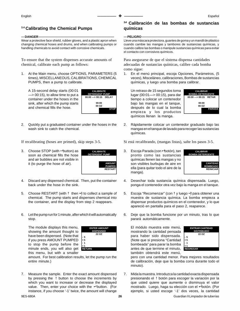
9ES-680A 26 Guardian II Limpiador de tuberías
English —————— v —————— Español
3.4 Calibrating the Chemical Pumps
— DANGER ————————————————————————Wear a protective face shield, rubber gloves, and a plastic apron whenchanging chemical hoses and drums, and when calibrating pumps orhandling chemicals to avoid contact with corrosive chemicals.
To ensure that the system dispenses accurate amounts ofchemical, calibrate each pump as follows:
1. At the Main menu, choose OPTIONS, PARAMETERS (5times), MISCELLANEOUS, CALIBRATIONS, CHEMICALPUMPS, then a pump to calibrate.
A 15-second delay starts (00:01—> 00:15), to allow time to put acontainer under the hoses in thesink, after which the pump startsand chemical fills the hose.
2. Quickly put a graduated container under the hoses in thewash sink to catch the chemical.
If recalibrating (hoses are primed), skip steps 3-5.
3. Choose STOP (with 8 button) assoon as chemical fills the hoseand air bubbles are not visible init (to purge the hose of air).
4. Discard any dispensed chemical. Then, put the containerback under the hose in the sink.
5. Choose RESTART (with # then 8) to collect a sample ofchemical. The pump starts and dispenses chemical intothe container, and the display from step 2 reappears.
6. Let the pump run for 1 minute, after which it will automaticallystop.
The module displays this menu,showing the amount thought tohave been dispensed. (Note thatif you press AMOUNT PUMPEDto stop the pump before theminute ends, you will also getthis menu, but with a smalleramount. For best calibration results, let the pump run theentire minute.)
7. Measure the sample. Enter the exact amount dispensedby pressing the # button to choose the increments bywhich you want to increase or decrease the displayedvalue. Then, enter your choice with the 8 button. (Forinstance, if you choose ‘-1’ twice, the amount will change
3.4 Calibración de las bombas de sustanciasquímicas
— PELIGRO ————————————————————————Lleve una máscara protectora, guantes de goma y un mandil de plásticocuando cambie las mangas y tambores de sustancias químicas, ycuando calibre las bombas o manipule sustancias químicas para evitarel contacto con corrosivos químicos.
Para asegurarse de que el sistema dispensa cantidadesadecuadas de sustancias químicas, calibre cada bombacomo sigue:1. En el menú principal, escoja Opciones, Parámetros, (5
veces), Misceláneo, calibraciones, Bombas de sustanciasquímicas, y luego una bomba para calibrar.
Un retraso de 15 segundos tomalugar (00:01—> 00:15), para dartiempo a colocar un contenedorbajo las mangas en el tanque,después de lo cual la bombaempieza y los productosquímicos llenan la manga.
2. Rápidamente colocar un contenedor graduado bajo lasmangas en el tanque de lavado para recoger las sustanciasquímicas.
Si está recalibrando, (mangas listas), salte los pasos 3-5.
3. Escoja Parada (con 8 botón), tanpronto como las sustanciasquímicas llenen las mangas y noson visibles burbujas de aire enella (para quitar todo el aire de lamanga).
4. Desechar toda sustancia química dispensada. Luego,ponga el contenedor otra vez bajo la manga en el tanque.
5. Escoja “Recomenzar” (con # y luego 8) para obtener unamuestra de sustancia química. La bomba empieza adispensar productos químicos en el contenedor, y lo queapareció en pantalla para el paso 2, reaparece.
6. Deje que la bomba funcione por un minuto, tras lo queparará automáticamente.
El módulo muestra este menú,mostrando la cantidad pensadapara haber sido dispensada.(Note que si presiona “Cantidadbombeada” para parar la bombaantes de que termine el minuto,también obtendrá este menú,pero con una cantidad menor. Para mejores resultadosde calibración, deje que la bomba corra durante todo elminuto).
7. Mida la muestra. Introduzca la cantidad exacta dispensadapresionando el # botón para escoger la variación por laque usted quiere que aumente o disminuya el valormostrado. Luego, haga su elección con el 8 botón. (Porejemplo, si usted escoge ‘-1’ dos veces, la cantidad
CALIBRATEDETERGENT PUMP
00:00 —> 00:15 DELAY
00:0000 OZ
STOP
CALIBRARBOMBA DETERGENTE
00:00 —> 00:15 RETAR
00:0000 OZ
PARADA
CALIBRATEDETERGENT PUMP
AMOUNTPUMPED
RESTART
CALIBRARBOMBA DETERGENTE
CANTIDADBOMBEADO
REINICIAR
ENTER AMOUNTDISPENSED
22 OZ- 5+ 5- 1+ 1RETURN
ENTRAR CANTIDADDISTRIBUIDO
22 OZ- 5+ 5- 1+ 1REGRESAR

Guardian II Pipeline Washer 27 9ES-680A
English —————— v —————— Español
from 22 to 20.) Move the bar cursor to RETURN (# button)and choose it (8 button) to return to the Calibrate ChemicalPumps menu.
Note that the module calculates the amount entered withthe dispense time to determine the flow rate. Note alsothat the amount you enter will be stored in memory onlyafter you RETURN to the Parameters Miscellaneousmenu.
8. Discard the dispensed chemical. Then thoroughly rinsethe container to remove chemical residue.
— DANGER ——————————————————————Do not mix acid with a chlorinated detergent or sanitizer, as toxicchlorine gas will be produced. To avoid mixing chemicals, alwaysempty and thoroughly clean the container before collecting adifferent chemical.
Repeat the procedure with the other pumps. Then,choose RETURN to back up to the MiscellaneousCalibrations menu. Choose VIEW PUMP FLOW RATE.Then, one at a time, choose a pump from the View PumpFlow Rate menu and see that their rates are similar. Incases where multiple pumps or higher viscosity chemicalsare used, rates may be different.
3.5 Calibrating the Temperature Sensor
To ensure that water dispenses into the sink at settemperatures, calibrate the temperature sensor with athermometer (known to be accurate) as follows:
1. Put about 3 to 6" (80 to 150 mm) of warm water in the sink,allow the water temperature to stabilize for about 5minutes, then measure it with the thermometer.
2. If the temperature shown in the display’s left screen doesnot match the actual temperature, RETURN through themenus to the Setup Miscellaneous Calibrations menu,and choose TEMPERATURESENSOR.
3. Enter the difference between thetemperatures by pressing the #button until the cursor highlightsthe increments by which you wantto increase or decrease thedisplayed value. Then, press the 8 button to enter yourchoice. (For instance, if the displayed temperature is 76°Fand the actual temperature is 81°F, resulting in a differenceof 5°, you would choose the ‘+5’ menu item.) Move thecursor to RETURN and choose it to enter the change.
pasará de 22 a 20). Mueva la barra del cursor a “Retorno”(# botón) y escójalo (8 botón) para volver al menú decalibración de las bombas de sustancias químicas.
Note que el módulo calcula la cantidad introducida con eltiempo de distribución para determinar la tasa de fluidez.Note también que la cantidad que usted introduzca seráarchivada en la memoria sólo después de que usted“Retorne” al menú de parámetros misceláneos.
8. Descarte las sustancias químicas dispensadas. Luegoaclare cuidadosamente el contenedor para eliminarresiduos químicos.— PELIGRO ——————————————————————No mezcle ácido con un detergente clorinado o desinfectante, puesgas de cloro tóxico puede producirse. Para evitar la mezcla desustancias químicas, vacíe siempre y limpie cuidadosamente elcontenedor antes de recoger sustancias químicas diferentes.
Repita el procedimiento con las otras bombas. Entoncesescoja “Retorno” para volver al menú de calibracionesmisceláneas. Escoja “Enseñar el caudal de la bomba.”Luego una cada vez, escoja una bomba del menú de“Enseñar el caudal de la bomba” y vea que sus tasas sonsimilares. En casos donde son usadas varias bombas osustancias químicas de mayor viscosidad, las tasas puedenser diferentes.
3.5 Calibración del sensor de temperatura
Para asegurar que el agua fluye en el tanque a lastemperaturas programadas, calibre el sensor detempuratura con un termómetro (que se sepa exacto) comosigue:
1. Ponga de 3" a 6" (80 a 150mm) de agua tibia en el tanque,deje que la temperatura del agua se estabilice unos 5minutos, y entonces mídala con el termómetro.
2. Si la temperatura mostrada a la izquierda de la pantalla noencaja con la temperatura real, “Retorno” a través de losmenús al menú del sistema de calibraciones misceláneasy, escoja “Sensor detemperatura.”
3. Introduzca la diferencia entre lastemperaturas presionando el #botón hasta que el cursor marquelas variantes por las que Ud.quiere aumentar o disminuir elvalor mostrado. Entonces, presione el 8 botón paraintroducir su elección. (Por ejemplo, si la temperaturamostrada es 76oF y la temperatura real es 81oF, y ladiferencia resultante es 5oF, Ud. escogería el elementodel menú “+5”). Mueva el cursor a “Retorno” y escójalopara introducir el cambio.
TEMPERATURE SENSORCORRECTION
0 F- 5+ 5- 1+ 1RETURN
SENSOR TEMPERATURACORRECCION
0 F- 5+ 5- 1+ 1REGRESAR

9ES-680A 28 Guardian II Limpiador de tuberías
English —————— v —————— Español
3.6 Setting Auxiliary Output Variables
Auxiliary OutputsIf an auxiliary output product was wired to the washer, youmust enable the washer to turn it on and off.
Starting at the Main menu, choose OPTIONS,PARAMETERS (5x), MISCELLANEOUS, INPUTS/OUTPUTS, then AUXILIARY OUTPUTS. Then, one at atime, choose an AUXILIARY (1-6) from the menu and...
...set it with the item in the nextmenu that corresponds to theproduct you assigned to thatauxiliary during installation.(Consult your record forassignments.)
If the product you installed is notlisted in the menu, choose MOREto have the module display otherproducts.
Choose a product (# button), asshown for alarm output. Then, enter your choice (8
button).
Plate Cooler Cold and Plate Cooler HotIf the washer is wired for the ‘Plate Cooler Cold’ and/or‘Plate Cooler Hot’ auxiliary option(s), you can specifyclassifications (cold, warm, hot, or water off) for water thatwill circulate through the coolant circuit of the plate coolerduring the various circulation portions of each phase. (Ifyou do not specify these, the system will automaticallycirculate hot water for the detergent phase and no water forall other phases.)
Wired as explained in Section 2, the auxiliary outputs willrespond as follows:
Plate PlateCold Water Hot Water Cooler Cooler
Classification Valve Valve Cold HotCOLD Open Closed Off OffWARM Open Open Off OnHOT Closed Open On OnWATER OFF Closed Closed On Off
Note that you can choose any classification for a phase, butyou should choose the most sensible one for the mosteffective cleaning.
Starting at the Main menu, chooseOPTIONS, PARAMETERS (5x),MISCELLANEOUS, INPUTS/OUTPUTS, PLATE COOLERWATER, then SANITIZEPHASES or WASH PHASES.Then, one at a time, choose a phase from the Plate CoolerWater menu and set its water valve.
AUXILIARY #
MORECOLD PC OUTPUTBOOSTER OUTPUTALARM OUTPUTREMOTE OUTPUTCYCLE ON OUTPUT
PLATE COOLER WATERFIRST WATER RINSE
COLDWARMHOTWATER OFF
AUXILIARY #
PREVIOUS MENUTIMER 3TIMER 2TIMER 1HOT PC OUTPUT
3.6 Establecimiento de las variables de las tomasde corriente auxiliares.Tomas de corriente auxiliaresSi un producto de toma de corriente auxiliar fue conectadoal limpiador, Ud. debe capacitar el limpiador paraencenderlo y apagarlo.Empezando en el menú principal, escoja “Opciones”,“Parámetros” (5x), “Misceláneos”, “Entradas/Salidas decorriente”, luego “Tomas de corriente auxiliares”.Entonces, uno cada vez escoja un “Auxiliar” (1-6) delmenú y......establézcalo con el elemento delsiguiente menú que corresponde alproducto que Ud. asignó al auxiliardurante la instalación. (Consultesu registro de asignaciones).
Si el producto que ha instalado noestá en el menú, escoja “Más” paraver el módulo de otros productos.
Escoja un producto (# botón),como se muestra para el dispositivo de alarma. Entonces,haga su elección (8 botón).
Placa refrigerante fría y placa refrigerante calienteSi el limpiador está conectado para las opciones auxiliares“Placa refrigerante fría” y/o la caliente, puede especificarclasificaciones (fría, templada, caliente, o cortar el agua)para el agua que circule a través del circuito refrigerante dela placa durante las diferentes porciones de circulación decada fase. (Si Ud. no especifica esto, el sistemaproporcionará automáticamente agua caliente para la fasede detergente y no habrá agua en las otras fases).
Conectados como se explicó en la sección 2, las tomas decorriente auxiliares responderán como sigue:
Placa PlacaAgua fría Agua caliente refrigerante refrigerante
Clasificación Válvula Válvula fría calienteFRIA Abierta Cerrada Apagada ApagadaTEMPLADA Abierta Abierta Apagada EncendidaCALIENTE Cerrada Abierta Encendida EncendidaAGUA CORTADA Cerrada Cerrada Encendida Apagada
Note que puede escoger cualquier clasificación para unafase, pero debe escoger la más sensata para la limpiezaefectiva.
Empezando en el menú principal,escoja “Opciones”, “Parámetros”(5x), “Misceláneos”, “Entradas/Salidas de la corriente”, “Placarefrigerante del agua”, “Fases dedesinfección” o “Fases de lavado”.Entonces, una cada vez, escoja una fase del menú de laplaca refrigerante del agua e instale su válvula de agua.
AUXILIAR #
MASPLACAS AGUA FRIASALIDA CALENTADORSALIDA ALARMASALIDA REMOTOSALIDA CICLO DENTRO
AUXILIAR #
MENU PREVIORELOJ 3RELOJ 2RELOJ 1PLACAS AGUA CALIENTE
AGUA INTERCAMBIADORCICLO PRE-ENJUAGUE
FRIOTIBIOCALIENTEAGUA-CERRAR

Guardian II Pipeline Washer 29 9ES-680A
English —————— v —————— Español
Timer 1, 2, and 3If the washer is wired for a ‘Timer’ auxiliary option, youcan specify the start and stop times for the auxiliaryproduct.
Starting at the Main menu, choose OPTIONS,PARAMETERS (5x), MISCELLANEOUS, INPUTS/OUTPUTS, TIMERS then, one at a time, choose a TIMER(1-3). At the next menu level, choose...
...one at a time DELAY FROMSTART and DELAY FROM END.
Change the value by pressing the #
button until the cursor highlightsthe increments by which you wantto increase or decrease it. Then, enter your choice with the8 button. (For instance, if you choose the ‘+5’ menuitem, the minutes field will change from 30 to 35.) Movethe bar cursor to RETURN (# button) and choose it (8button) to shift the value cursor from the ‘minutes’ field to‘seconds’. Change the seconds in the same way explainedfor minutes. Then, move the cursor to RETURN andchoose it again to go to the next menu.
3.7 Entering System Setup Data
Baud RateIf a printer or computer will be used, you must set themodule’s RS-232 baud rate to match that of the printerand/or computer for proper communications.
Starting at the Main menu, choose OPTIONS,PARAMETERS (5x), MISCELLANEOUS, SYSTEMSETUP, then RS-232 BAUD RATE.
Choose a rate (# button), as shownfor 9600 baud. Then, enter yourchoice (8 button). (Always use9600 baud with serial printers3556397 [115VAC] and 3556421[230VAC].)
Dairy NameA dairy farm name can be entered into the module that willappear at the top of printed reports.
Starting at the Main menu, choose OPTIONS,
Reloj 1, 2 y 3Si el limpiador está conectado para la opción auxiliar del“reloj”, puede especificar los tiempos de inicio y paradapara el producto auxiliar.
Empezando en el menú, escoja “Opciones”, “Parámetros”(5x), “Misceláneos”, “Entradas/ Salidas de la corriente”,“Relojes”, y luego, una cada vez, escoja un reloj (1-3). Enel siguiente nivel del menú, escoja...
...uno cada vez, “retraso del inicio”y “retraso del final”.
3.7 Introducción del sistema de preparación dedatos
Tasa de BaudioSi se usan una impresora o un ordenador, debe instalar elmódulo RS-232 de tasa de baudio para igualarla a la de laimpresora y\o ordenador para tener comunicacionesadecuadas.
Empezando en el menú principal, escoja “Opciones”,“Parámetros” (5x), “Misceláneos”, “Preparación delsistema”, y entonces la tasa de baudio RS-232.
Escoja una tasa (# botón), como semuestra para 9600 baudios.Entonces, introduzca su elección(8 botón). (Use siempre 9600baudios con las impresoras serie3556397 [115VAC] y 3556421[230VAC].)
Nombre de la granjaEl nombre de la granja puede introducirse en el móduloque aparecerá al principio de los datos impresos.
Empezando en el menú principal, escoja “Opciones”,
TIMER 1DELAY FROM START
00:30- 60+ 60- 5+ 5RETURN
RELOJ 1RETARDO DE INICIO
00:30- 60+ 60- 5+ 5REGRESAR
SYSTEM SETUPRS-232 BAUD RATE
960024001200600300RETURN
FIJAR SISTEMAVELOCIDAD RS-232
960024001200600300REGRESAR

9ES-680A 30 Guardian II Limpiador de tuberías
English —————— v —————— Español
“Parámetros” (5x), “Misceláneos”, “Preparación delsistema”, y entonces “Nombre de la granja”. El menú delnombre de la granja muestra, con el nombrepreprogramado, “Su nombre”, en lo alto del menú. Laprimera letra del nombre está marcada y lista para elcambio.
Cambie la letra presionando el # botón hasta que el cursormarque “enrollar” o “desenrollar” (dependiendo de ladirección en que quiera moverse a través del alfabetodesde la letra marcada). Presione el 8 botón hasta queobtenga la letra deseada (por ejemplo “V” presionando 3veces, como se indicó). Entonces, mueva el cursor de labarra hasta una flecha y escójala para mover el cursor delnombre hasta la próxima letra que quiera cambiar. Alterneentre los elementos de enrollar y desenrollar y la flechahasta que todas las letras estén como desea. Mueva elcursor de la barra hasta “Return” y escójalo para introducirel nombre y salir del menú.
Luminosidad de la pantallaLa intensidad y el contraste de la imagen en la pantalla dellimpiador puede ser cambiada, si se desea.
Empezando en el menú principal,escoja “Opciones”, “Parámetros”(5x), “Misceláneos”, “Preparacióndel sistema”, y entonces“Luminosidad del sistema”.
Cambie la intensidad presionando el (# botón para cambiarla intensidad del valor mostrado.<<<......>>> (Porejemplo, si escoge “+1”, la intensidad cambiaráa de 160 a161) mueva el cursor a “Retorno” y escójalo paraintroducir el cambio.
La capacidad de los valores de intensidad es de alrededor 110(el más claro) a 190 (más oscuro). En algún momento deldesplazamiento hacia alguno de los dos lados del espectro, laimagen aparecerá demasiado clara o demasiado oscura paraque los datos puedan ser leídos. Para poder mejorar esto,continue presionando el 8 botón hasta que la imagen muestredatos legibles. (Una vez que se llega al final, el valor de laintensidad se revierte al otro extremo del espectro, por lo quepuede continuar incrementando). Pare a la intensidad deseada.Si la intensidad es muy ligera u oscura y la visualización no sepuede leer, abra la cubierta del frente y presione repetidamenteel botón (S2) de “Display Intensity” (Visualizando laIntensidad) en la caja de cuadros del CPU, hasta que laintensidad deseada sea alcanzada.
PARAMETERS (5x), MISCELLANEOUS, SYSTEMSETUP, then DAIRY NAME. The Dairy Name menudisplays, with a factory-entered name, ‘YOUR NAME,’ inthe top menu position The first letter of the name ishighlighted and ready for change.
Change the letter by pressing the # button until the cursorhighlights either SCROLL UP or SCROLL DOWN(depending on the direction you want to move through thealphabet from the highlighted letter). Press the 8 buttonuntil you get the letter you want (for instance ‘V, ’pressing3 times as shown). Then, move the bar cursor to an arrow(Ò) and choose it to move the name cursor to the nextletter you want to change. Alternate between the ‘scroll’and ‘arrow’ menu items until all letters are as you wantthem. Move the bar cursor to RETURN and choose it toenter the name and exit the menu.
Display IntensityIntensity and contrast of the washer’s display can bechanged, if desired.
Starting at the Main menu, chooseOPTIONS, PARAMETERS (5x),MISCELLANEOUS, SYSTEMSETUP, then DISPLAYINTENSITY.
Change the intensity by pressing the # button until thecursor highlights the increments by which you want toincrease or decrease it. Press the 8 button to change theintensity and displayed value. (For instance, if you choose‘+1’, the intensity will change from 160 to 161.) Move thecursor to RETURN and choose it to enter the change.
The range of intensity values is about 110 (lightest) to 190(darkest). At some point in moving toward either end ofthe range, the display will become too light or too dark fordata to be read. Should you increment that far, continuepressing the 8 button until the display again showsreadable data. (Upon reaching either end, the value andintensity revert to the extreme end of the range so you cancontinue incrementing.) Stop at the desired intensity.If the intensity is too light or dark and the display can notbe read, open the front cover and repeatedly press the"Display Intensity" button (S2) on the CPU board until thedesired intensity is reached.
V
SYSTEM SETUPDAIRY NAME
YOUR NAMESCROLL DOWNSCROLL UP<——>RETURN
XW
V
FIJAR SISTEMANOMBRE GRANJA
YOUR NAMEABAJOARRIBA<——>REGRESAR
XW
SYSTEM SETUPDISPLAY INTENSITY
160- 5+ 5- 1+ 1RETURN
FIJAR SISTEMALUMINOSIDAD PANTALLA
160- 5+ 5- 1+ 1REGRESAR

Guardian II Pipeline Washer 31 9ES-680A
English —————— v —————— Español
— Note ——————————————————————————We recommend that you change intensity by increments of 1, becauseintensity changes are less drastic than with increments of 5. Note, also,that you can change intensity any time by pressing the S2 button (DisplayIntensity) on the CPU board in the electrical module. Intensity willincrease as if you were entering the ‘+1’ menu item.
Print the ParametersPrint the Parameters is a washer function that can be usedif a printer or computer is interfaced to the washer. Thefunction prints/displays current setup data for reference.A printout is valuable in case of failure of the control.Print this after finalizing all settings, and after changingsettings in the future.
Starting at the Main menu, choose OPTIONS,PARAMETERS (5x), MISCELLANEOUS, SYSTEMSETUP, then PRINT THE PARAMETERS.
3.8 Entering Control Variables
Control variables are bits of data particular to the system.Following are definitions of the variables andrecommended settings for some of them:
• Sink Capacity—the amount of water in the sink whenthe fill switch activates. You need only enter a value forthis variable if the sink is undersized (unable to hold allwater needed for each cleaning phase). Then, specify theamount of extra water (explained in Section 3.9) neededfor each phase.
• Fill Time Limit —shuts off water to prevent the sinkfrom overfilling in the event that the fill switch or drainmalfunctions. Set the limit for a few minutes more thanthe time needed to activate the fill switch.
• Fill Temperature Stability —the tolerance within whichthe washer holds the solution temperature while the sinkfills. A reasonable setting is 3°F (2°C).
• Pump Delays—a delay for each chemical pump thatbegins when water starts to fill and ends with the chemicalpump starting. Set as long a delay as possible for eachpump (to prevent chemical damage to the wash sink), yetallowing time for the chemical to mix with water beforecirculating through the system.
• Print Frequency—the number of times each minuteduring fill and circulation that the washer sends currenttime and temperature data to the printer or computer. Thedefault setting is 6 times/minute.
Menus for setting the variables are accessed through theMiscellaneous Control Variables menu. To get to thatmenu, starting at the Main menu, choose OPTIONS,PARAMETERS (5x), MISCELLANEOUS, thenCONTROL VARIABLES. Then, follow the ‘variable’setting instructions, below.
— Nota ——————————————————————————Recomendamos que varíen la intensidad en valores de 1, porque loscambios de intensidad son menos drásticos que con incrementos de 5.Note también que puede cambiar la intensidad en cualquier momentopresionando el botón S2 (Luminosidad de la pantalla) en el tablero CPUen el módulo el_ctrico. La intensidad se incrementará como si ustedestuviera introduciendo el elemento del menú “+1”.
Impresión de los parámetrosLa impresión de los parámetros es una función dellimpiador que puede ser usada si una impresora uordenador está conectado al limpiador. La funciónimprime/representa datos del sistema del memento comoreferencia. Una impresión en papel es valiosa en caso deun fallo del control. Imprima esto después de haberorganizado todos los datos, y después de cambiar estosdatos en el futuro.Empezando en el menú principal, escoja “Opciones”,“Parámetros” (5x), “Misceláneos”, “Preparación delsistema”, y entonces “Impresión de parámetros”.
3.8 Introducción de las variables de control
Las variables de control son porciones de datos particularesal sistema. Lo siguiente son definiciones de variables ypreparación de sistemas recomendados para algunos deellos:
• Capacidad del tanque—la cantidad de agua en el tanquecuando se activa el interruptor de llenado. Sólo necesitaintroducir un valor para esta variable si el tanque es máspequeño de lo normal (incapaz de contener todo el aguanecesaria para cada fase de limpieza). Entonces,especifique la cantidad de agua extra (explicado en lasección 3.9) necesitada para cada fase.
• Límite del tiempo de llenado—corta el agua para impedirque el tanque se llene demasiado en caso de que elinterruptor de llenado o el drenaje no funcionen bien.Establezca el límite por unos pocos minutos más que eltiempo necesario para activar el interruptor de llenado.
• Estabilidad de la temperatura de llenado—la toleranciadentro de la cual el limpiador mantiene la temperatura dela solución mientras el tanque se llena. Una temperaturarazonable es 3oF (2oC).
• Retrasos en las bombas—un retraso para cada bomba desustancias químicas que empieza cuando el agua empiezaa llenarse y termina cuando las bombas de sustanciasquímicas empiezan. Establezca un retraso para cadabomba tan largo como sea posible (para prevenir del dañoquímico al tanque de lavado), aunque dejando tiempopara que las sustancias químicas se mezclen con el aguaantes de circular por el sistema.
• Frecuencia de impresión—el número de veces en quecada minuto durante el llenado y circulación el limpiadorenvía los datos de tiempo y temperatura en curso a laimpresora o al ordenador. El sistema de fallos funciona6 veces por minuto.
Los menús para establecer las variables son accesibles através del menú de Misceláneos y control de variables.Para llegar a este menú, empezando en el menú principal,escoja “Opciones”, “Parámetros” (5x), “Misceláneos”, yentonces, “Control de variables”. Entonces, siga lasinstrucciones para el establecimiento de 'variables' (acontinuación).

9ES-680A 32 Guardian II Limpiador de tuberías
English —————— v —————— Español
Note that instructions are presented more simply here thanin earlier sections, but that entry of data is the same.Change the value by pressing the # button until the cursorhighlights the increments by which you want to increase ordecrease it. Then, enter your choice with the 8 button.Move the bar cursor to RETURN (# button) and choose it(8 button) to exit the menu.
To help you find your way among the menu levels,references to certain parts (for example, “part 12”) of thecomplete menu structure (in Section 7) have been includedin the instructions.
Sink CapacityFrom the Miscellaneous Control Variables menu (part 12),choose SINK CAPACITY.
Change the value as explainedabove. (Example: If you choose‘+5’ twenty times, the amount willchange from 0 to 100.)
Fill Time LimitFrom the Miscellaneous Control Variables menu (part 12),choose FILL TIME LIMIT.
Change the value by pressing the #
button until the cursor highlightsthe increments by which you wantto increase or decrease it. Then,enter your choice with the 8button. Move the bar cursor toRETURN (# button) and choose it (8 button) to shift thevalue cursor from the ‘minutes’ field to ‘seconds’. Changethe seconds in the same way explained for minutes. Then,move the cursor to RETURN and choose it again to exitthe menu.
Note that the maximum time is 30 minutes.
Fill Temperature StabilityFrom the Miscellaneous Control Variables menu (part 12),choose FILL TEMP STABILITY.
Change the value as explainedabove.
Note que las instrucciones se presentan de forma mássimple’ aquí que en las primeras secciones, pero que laentrada de datos es la misma. Cambie el valor presionandoel # botón hasta que el cursor marque las variaciones porlas que quiere aumentarlo o disminuirlo. Entoncesintroduzca su elección con el 8 botón Mueva la barra delcursor a “Retorno” (# botón) y escójalo (8 botón) parasalir del menú.
Para ayudarle a orientarse a través de los niveles de menú,se han incluido en las instrucciones referencias a ciertaspartes (por ejemplo, “parte 12”) de la estructura completadel menú (en la sección 7).
Capacidad del tanqueEscoja “Capacidad del tanque” del menú de Misceláneos ycontrol de variables.
Cambie el valor como se explicómás arriba. (Ejemplo: si escoge“+5” veinte veces, la cantidadcambiará de 0 a 100).
Límite del tiempo de llenadoDel menú de Misceláneos y control de variables (parte 12),escoja “Límite del tiempo de llenado”.
Cambie el valor presionando el #
botón hasta que el cursor marquelas variantes por las que ustedquiere aumentar o disminuirlo.Introduzca entonces su eleccióncon el 8 botón. Mueva el cursorde la barra a “Retorna” (# botón) y escójalo (8 botón)para cambiar el cursor de valor del campo de los “minutos”al de los “segundos”. Cambie los segundos del mismomodo en que cambió los minutos. Entonces mueva elcursor a “retorno” y escójalo otra vez para salir del menú.
Note que el tiempo máximo son 20 minutos.
Estabilidad de la temperatura de llenadoEscoja “Estabilidad de la temp. de llenado” del menú deMisceláneos y control de variables (parte 12).
Cambie el valor como se explicóantes.
CONTROL VARIABLESSINK CAPACITY
0 GAL- 5+ 5- 1+ 1RETURN
VARIABLES DE CTRLVOLUMEN TINA
0 GAL- 5+ 5- 1+ 1REGRESAR
CONTROL VARIABLESFILL TIME LIMIT
20:00- 5+ 5- 1+ 1RETURN
VARIABLES DE CTRLTIEMPO MAX. LLENADO
20:00- 5+ 5- 1+ 1REGRESAR
CONTROL VARIABLESFILL TEMP STABILITY
3 F- 5+ 5- 1+ 1RETURN
VARIABLES DE CTRLESTABILIDAD TEMP. LL
3 F- 5+ 5- 1+ 1REGRESAR

Guardian II Pipeline Washer 33 9ES-680A
English —————— v —————— Español
Pump DelaysFrom the Miscellaneous Control Variables menu (part 12),choose PUMP DELAYS. Then, one at a time, choose apump and set their times as shown for this pump:
Change the value as explainedabove.
Print FrequencyFrom the Miscellaneous ControlVariables menu (part 12), choosePRINT FREQUENCY.
Change the value as explainedabove.
3.9 Setting the Phase Variables
Phase variables are bits of data particular to a phase.Following are definitions of the variables andrecommended settings for some of them:
• Chemical Amounts—the amount of chemical to be dispensedwhile the sink fills. A feature is that if a chlorine sanitizer isused, chlorine may be added to the detergent (detergent chlorineamount).
• Extra Chemical—an amount of chemical to be dispensed afterthe sink has filled.
• Fill Temperature—the desired temperature of water as it fillsthe sink.
• Fill Alarm Temperature —a temperature somewhat lowerthan Fill Temperature that activates an alarm if water does notreach the Fill Temperature when the fill switch activates. Areasonable setting is 10° to 15°F (7°C) below Fill Temperature.
• Cycle Times—periods (as follows) which comprise the variousportions of each phase.Circulation Time—a period during which the vacuum pumpoperates to circulate clear water or wash solution. Set this timefor the first water rinse phase such that the sink nearly empties(but water still covers the end of the suction line to minimizethe drying of residues on the equipment).Drain Time—a period, from the end of Circulation Time untilthe start of Air Dry Time, during which the vacuum pump staysoff to allow the milk meter enough time to drain. Set this timeto ‘0’ if milk meters or weigh jars will not be used.Air Dry Time—period during which the vacuum pump operateswith the drain and diverter valves open to remove remainingwater from the milk line and hoses.
DETERGENT PUMPDELAY TIME
00:30- 60+ 60- 5+ 5RETURN
CONTROL VARIABLESPRINT FREQUENCY
6 TIMES/MIN- 5+ 5- 1+ 1RETURN
Retrasos de la bombaEscoja “Retrasos de la bomba” del menú de Misceláneos ycontrol de variables (parte 12). Entonces, una cada vez,escoja una bomba y establezca los tiempos como semuestra para esta bomba:
Cambie los valores como seexplicó antes.
Frecuencia de impresiónEscoja “Frecuencia de impresión”del menú de Misceláneos y controlde variables (parte 12).
Cambie los valores como seexplicó antes.
3.9 Establecimiento de las variables de fase
Las variables de fase son porciones de datos específicos decada fase. Lo siguiente son definiciones de las variables ylos programas recomendados para algunas de ellas:
• Cantidad de productos químicos—la cantidad de sustanciasquímicas que deben ser dispensadas mientras se llena eltanque. Una característica es que si un desinfectante de clorinase usa, la clorina puede ser añadida al detergente (cantidad dedetergente de clorina).
• Sustancias químicas extra—una cantidad de sustanciasquímicas para ser dispensadas después de que el tanque se hallenado.
• Temperatura de llenado—la temperatura a la que se desea elagua mientras llena el tanque.
• Temperatura de la alarma de llenado—una temperaturaalgo más baja que la Temperatura de llenado que activa unaalarma si el agua no alcanza la temperatura de llenado cuandose activa el interruptor de llenado. Una programación razonablees de 10o a 15o F (7oC) por debajo de la temperatura de llenado.
• Tiempos de ciclo—Periodos (a continuación) que comprendenvarias porciones de cada fase.Tiempo de circulación—periodo durante el cual la bomba devaciado funciona para hacer circular agua limpia o solución delavado. Establezca este tiempo para la fase del primer aclaradode agua de modo que el tanque casi se vacíe (pero el aguatodavía cubre el final del tubo de succión para minimizar elsecado de residuos en el equipo).Tiempo de drenaje—periodo desde el final del Tiempo decirculación hasta el principio del Tiempo de secado con aire,durante el cual la bomba de vaciado permanece apagada parapermitir que el contador de la leche tenga suficiente tiempopara drenarse. establezca este tiempo en “0” si el contador dela leche o los contenedores para pesar no van a ser usados.Tiempo de secado con aire—periodo durante el cual la bombade vaciado funciona con las válvulas de drenaje y desvíoabiertas para retirar el agua que queda en el tubo de la leche ylas mangas.
BOMBA DETERGENTETIEMPO RETARDO
00:30- 60+ 60- 5+ 5REGRESAR
VARIABLES DE CTRLIMPRIMIR FREQUENCIA
6 VECES/MIN- 5+ 5- 1+ 1REGRESAR

9ES-680A 34 Guardian II Limpiador de tuberías
English —————— v —————— Español
• Circulation Stop Temperature—the minimum circulationtemperature for solutions of detergent or acid. If temperaturesfall to this setting, circulation will stop to prevent residue fromredepositing on equipment. The Circulation-Minimum Timeoverrides this function to ensure at least minimal cleaning.Circulation-Minimum Time—a period during which solutionsof detergent or acid circulate regardless of the setting forCirculation Stop Temperature.Circulation-Alarm Time—a period during which an alarm willactivate if circulation should stop before the Circ-Alarm Timeends. Choose a setting that is greater than Circulation-Minimum Time but less than Circulation Time.
• Diverter Delay Time—a delay that starts when the vacuumpump turns on and ends when the diverter valve turns on. Setthe delay so that the first 2 or 3 returning slugs drain away fromthe sink.
• Sanitize Start Times—the times of day when the automaticsanitize cycle is to start. Ensure that the system clock is set tocurrent time.
• Extra Water —an amount of water that is added, after the startof circulation, if the Sink Capacity amount is not enough. Thetime to reach the sink Capacity is used to calculate a flow rate,which is used to add extra water.
Menus for setting the variables are accessed through theParameters Phase Setup menu. To get to that menu,starting at the Main menu, choose OPTIONS,PARAMETERS (5x), then PHASE SETUP. Then, followthe ‘variable’ setting instructions below.
Note that instructions are presented more simply here thanin earlier sections, but that entry of data is the same.Change the value by pressing the # button until the cursorhighlights the increments by which you want to increase ordecrease it. Then, enter your choice with the 8 button.Move the bar cursor to RETURN (# button) and choose it(8 button) to exit the menu.
To help you find your way among the menu levels,references to certain parts (for example, “part 4”) of thecomplete menu structure (in Section 7) have been includedin the instructions.
Chemical AmountsFrom the Parameters Phase Setup menu, choose one at atime WASH PHASES and SANITIZE PHASES. At thenext menu in each structure, choose DETERGENT PHASE(part 4), ACID PHASE (part 6), and SANITIZE PHASE(part 8). Next, choose AMOUNTS. Then, one at a time,choose...
• Temperatura de parada de la circulación — la temperaturade circulacióm mínima para soluciones de detergente o ácido.Si la temperatura baja en este programa, la circulación sedetendrá para evitar que los residuos se redepositen en elequipo. El Tiempo mínimo de circulación domina esta funciónpara asegurar un mínimo de limpieza.
Tiempo de alarma en la circulación—un periodo durante elcual una alrma se activará si si la circulación se para antes deque el Tiempo de alarma de la circulación se termine. Escojaun programa que sea mayor que el Tiempo mínimo de circulaciónpero menor que el Tiempo de Circulación.
. Tiempo de retraso del desvío—un retraso que empieza cuandola bomba de vaciado se enciende y termina cuando la válvulade desvío se apaga. Establezca el retraso de tal forma que las2 o 3 primeras unidades de masa se drenen del tanque.
. Tiempo para empezar la desinfección— los momentos deldía en que el ciclo de desinfección automática empieza.Asegúrese de que la hora del reloj del sistema es correcta.
. Agua extra—una cantidad de agua que se añade, una vezcomenzada la circulación , si la cantidad de la capacidad deltanque no es sufieciente. El tiempo para alcanzar la capacidaddel tanque se usa para calcular la tasa de afluencia, que es usadapara añadir agua extra.
Menús para el establecimiento de variables a las que seaccede a través del menú que establece la fase deparámetros. Para llegar a este menú, empezando en elmenú principal, escoja “Opciones”, “Parámetros” (5x) yentonces “Establecimiento de fase”. Entonces, siga lasinstrucciones del establecimiento de variables que sigue.
Note que las instrucciones son más simples aquí que en lassecciones anteriores, pero la entrada de datos es la misma.Cambie el valor presionando el # botón hasta que el cursormarque las variaciones por las cuales quiere aumentarlo odisminuirlo. Entonces introduzca su elección con el 8
botón. Mueva el cursor de la barra a “Retorno” (# botón) yescójalo (8 botón) para salir del menú.
Para ayudarle a orientarse entre los diferentes niveles delmenú, referencias a algunas partes (por ejemplo, “parte 4”)de la estructura completa del menú (en la sección 7) se hanincluido en las instrucciones.
Cantidades de sustancias químicasDel menú que establece la fase de parámetros, escoja, unacada vez, “Fases de lavado” y “Fases de desinfección”. Enel siguiente menú, en cada estructura, escoja “Fase dedetergente” (parte 4), “Fase del ácido” (parte 8). Luego,escoja “Cantidades”. Entonces, una cada vez, seleccione...

Guardian II Pipeline Washer 35 9ES-680A
English —————— v —————— Español
...DETERGENT AMOUNT andDETERGENT CHLORINEAMOUNT under the DetergentPhase Amounts menu to get a finalmenu such as this. Change thevalue as explained above.
— DANGER ————————————————————————Do not use an acid sanitizer, or deadly chlorine gas could be producedby mixing of chemicals.
...ACID AMOUNT under the AcidPhase Amounts menu to get thismenu. Change the value asexplained above.
...SANITIZER AMOUNT underthe Sanitize Phase Amounts menuto get this menu. Change the valueas explained above.
Extra ChemicalFrom the Parameters Phase Setup menu, choose one at atime WASH PHASES and SANITIZE PHASES. At thenext menu level, choose DETERGENT PHASE (part 4),ACID PHASE (part 6), and SANITIZE PHASE (part 8).Next, choose AMOUNTS. Then, one at a time, choose...
...EXTRA DETERGENT and EXTRA CHLORINE underthe Detergent Phase Amounts menu to get a final menu.
...EXTRA ACID under the Acid Phase Amounts menu toget a final menu.
...EXTRA SANITIZER under the Sanitize Phase Amountsmenu to get a final menu.
Change the value in each menu as explained above .
DETERGENT PHASEDETERGENT AMOUNT
5 OZ- 5+ 5- 1+ 1RETURN
ACID PHASEACID AMOUNT
0 OZ- 5+ 5- 1+ 1RETURN
SANITIZE PHASESANITIZER AMOUNT
0 OZ- 5+ 5- 1+ 1RETURN
...”Cantidad de detergente” y“Cantidad del detergente de cloro”bajo el menú de las cantidades dela fase de detergente para llegar aun menú final como este. Cambielos valores como se explicó másarriba.
— PELIGRO ————————————————————————No use un desinfectante ácido, o podría producirse gas de cloro mortalal mezclar las sustancias químicas.
...CANTIDAD DE ACIDO bajo elmenú de las cantidades de la fasede ácido para llegar a este menú.Cambie el valor como se explicóarriba.
...CANTIDAD DEDESINFECTANTE bajo el menúde las cantidades de la fase dedesinfección para llegar a estemenú. Cambie el valor como seexplicó arriba.
Sustancias químicas extraDel menú que establece la fase de parámetros, seleccione,una cada vez, “Fases de lavado” y “Fases de desinfección”.En el siguiente nivel del menú escoja “Fase de detergente”(parte 4), “Fase del ácido” (parte 6), y “Fase dedesinfección” (parte 8). Luego seleccione “Cantidades”.Entonces, una cada vez, seleccione...
...DETERGENTE EXTRA y CLORO EXTRA, bajo elmenú de las cantidades de la fase de detergente para llegaral menú final.
...ACIDO EXTRA bajo el menú de las cantidades de lafase de ácido para llegar al menú final.
...DESINFECTANTE EXTRA bajo el menú de cantidadesde la fase de desinfección para llegar al menú final.
Cambie el valor en cada menú como se explicó arriba.
CICLO ALCALINOCANTIDAD DETERGENTE
5 OZ- 5+ 5- 1+ 1REGRESAR
CICLO ACIDOCANTIDAD ACIDO
0 OZ- 5+ 5- 1+ 1REGRESAR
CICLO DESINFECCIONCANTIDAD DESINFECTAN
0 OZ- 5+ 5- 1+ 1REGRESAR

9ES-680A 36 Guardian II Limpiador de tuberías
English —————— v —————— Español
Fill TemperatureFrom the Parameters Phase Setup menu, choose one at atime WASH PHASES and SANITIZE PHASES. At thenext menu level, choose...
...FIRST WATER RINSE (part 3),then FILL TEMPERATURE to getthis menu. Change the value asexplained above.— Warning —————————————High water temperatures may "bake" onmilk protein to the pipeline componentsduring the rinse phase.
...DETERGENT PHASE (part 4),TEMPERATURES, then FILLTEMPERATURE to get this menu.Change the value as explainedabove.
...SECOND WATER RINSE (part5), then FILL TEMPERATURE toget this menu. Change the value asexplained above.
...ACID PHASE (part 6),TEMPERATURES, then FILLTEMPERATURE to get this menu.Change the value as explainedabove.
...THIRD WATER RINSE (part 7),then FILL TEMPERATURE to getthis menu. Change the value asexplained above.
...SANITIZE PHASE (part 8), thenFILL TEMPERATURE to get thismenu. Change the value asexplained above.
...SANITIZE WATER RINSE (part9), then FILL TEMPERATURE toget this menu. Change the value asexplained above.
Fill Alarm TemperatureFrom the Parameters Phase Setup menu, choose WASHPHASES, then one at a time DETERGENT PHASE (part4) and ACID PHASE (part 6). Next, chooseTEMPERATURES. Then, choose...
Temperatura de llenadoDel menú que establece la fase de parámetros, seleccione,una cada vez, las “fases de lavado” y “fases dedesinfección”. En el siguiente nivel del menú, seleccione...
...PRIMER ACLARADO DELAGUA (parte 3), luego“Temperatura de llenado” parallegar a este menú. Cambie el valorcomo se explicó arriba.— Precaución————————————Agua a altas temperaturas puede “cocer” laproteína de la leche en los componentes delconducto durante la fase del aclarado.
...FASE DEL DETERGENTE(parte 4), “temperaturas”, luego“temperatura de llenado” parallegar a este menú. Cambie el valorcomo se explicó.
...SEGUNDO ACLARADO DELAGUA (parte 5), luego“Temperatura de llenado” parallegar a este menú. Cambie el valorcomo se explicó.
...FASE DEL ACIDO (parte 6),“Temperaturas”, entonces“Temperatura de llenado” parallegar a este menú. Cambie elvalor como se explicó.
...TERCER ACLARADO DELAGUA (parte 7), luego“Temperatura de llenado” parallegar a este menú. Cambie el valorcomo se explicó.
...FASE DESINFECTANTE (parte8), luego “Temperatura de llenado”para llegar a este menú. Cambie elvalor como se explicó.
...DESINFECCION DELACLARADO (parte 9), luego“Temperatura de llenado parallegar a este menú. Cambie elvalor como se explicó.
Temperatura de la alarma de llenadoDel menú que establece la fase de parámetros, seleccione“Fases de lavado”, entonces, una cada vez, “Fase dedetergente” (parte 4) y “Fase ácido” (parte 6). Luego,seleccione “Temperaturas”. Entonces, escoja...
FIRST WATER RINSEFILL TEMPERATURE
105 F- 5+ 5- 1+ 1RETURN
DETERGENT PHASEFILL TEMPERATURE
185 F- 5+ 5- 1+ 1RETURN
CICLO ALCALINOTEMPERATURA LLENADO
185 F- 5+ 5- 1+ 1REGRESAR
AGUA PRIMER ENJUAGUETEMPERATURA LLENADO
105 F- 5+ 5- 1+ 1REGRESAR
AGUA SEGUNDO LAVADOTEMPERATURA LLENADO
40 F- 5+ 5- 1+ 1REGRESAR
CICLO ACIDOTEMPERATURA LLENADO
40 F- 5+ 5- 1+ 1REGRESAR
SECOND WATER RINSEFILL TEMPERATURE
40 F- 5+ 5- 1+ 1RETURN
ACID PHASEFILL TEMPERATURE
40 F- 5+ 5- 1+ 1RETURN
THIRD WATER RINSEFILL TEMPERATURE
40 F-5+5-1+1
RETURN
SANITIZE PHASEFILL TEMPERATURE
100 F-5+5-1+1
RETURN
SANITIZE WATER RINSEFILL TEMPERATURE
40 F-5+5-1+1
RETURN
AGUA 3ER ENJUAGUETEMPERATURA LLENADO
40 F-5+5-1+1
REGRESAR
CICLO DESINFECCIONTEMPERATURA LLENADO
100 F-5+5-1+1
REGRESAR
ENJUAGAR DESINFECT.TEMPERATURA LLENADO
40 F-5+5-1+1
REGRESAR

Guardian II Pipeline Washer 37 9ES-680A
English —————— v —————— Español
DETERGENT PHASEFILL ALARM TEMP
160 F- 5+ 5- 1+ 1RETURN
...FILL ALARM TEMP (forDetergent and Acid Phases only)to get a final menu such as this.Change the value as explainedabove.
Cycle TimesFrom the Parameters Phase Setup menu, choose one at atime WASH PHASES and SANITIZE PHASES. At thenext menu level, choose a ‘... PHASE’ or ‘...RINSE’ menuitem (parts 3, 4, 5, 6, 7, 8 & 9), TIMES, then one at atime...
...CIRCULATION TIME to get afinal menu (as shown for FirstWater Rinse). Change the value asexplained above.
...DRAIN TIME to get a finalmenu (as shown for First WaterRinse). Change the value asexplained above.
...AIR DRY TIME to get a finalmenu (as shown for First WaterRinse). Change the value asexplained above.
Circulation Stop TemperatureFrom the Parameters Phase Setup menu, choose WASHPHASES, then one at a time...
...DETERGENT PHASE (part 4),TEMPERATURES, then CIRCSTOP TEMP. Change the value asexplained above.
...ACID PHASE (part 6),TEMPERATURES, then CIRCSTOP TEMP. Change the value asexplained above.
...DETERGENT PHASE (part 4) orACID PHASE (part 6), TIMES,then CIRC.-MINIMUM TIME (forDetergent and Acid Phases only) toget this menu. Change the value asexplained above.
...TEMPERATURA DE ALARMADE LLENADO (sólo para las fasesdetergente y ácido) para llegar a unmenú final como este. Cambie elvalor como se explicó.
Tiempo de los ciclosDel menú que establece la fase de parámetros, seleccione“Fases de lavado” y “Fases de desinfección”, una cada vez.En el siguiente nivel del menú escoja un elemento delmenú de “Fase” o “Aclarado” (partes 3,4,5,6,7,8 y 9),“Tiempo, y una cada vez...
...TIEMPO DE CIRCULACIONpara llegar al menú final (como semuestra para el “Primer aclaradocon agua”). Cambie el valor comose explicó.
...TIEMPO DE DRENAJE parallegar al menú final (como semuestra para el “Primer aclaradocon agua”). Cambie el valor comose explicó.
...TIEMPO DE SECADO CONAIRE para llegar al menú final(como se muestra para el “Primeraclarado con agua”). Cambie elvalor como se explicó.
Temperatura de la parada de circulaciónDel menú que establece la fase de parámetros, escoja“Fases de lavado”; entonces, una cada vez...
...FASE DE DETERGENTE (parte4), luego TEMPERATURAS,luego TEMP. PARADA CIRC.Cambie el valor como se indicó.
...FASE ACIDO (parte 6),TEMPERATURAS, luego TEMP.PARADA CIRC. Cambie el valorcomo se indicó.
...FASE DETERGENTE (parte 4)o “fase acido” (parte 6), “Tiempo”,luego “Tiempo mínimo circ.” (sólopara las fases detergente y Acido)para llegar a este menú. Cambie elvalor como se explicó.
CICLO ALCALINOTEMP ALARMA LLENADO
160 F- 5+ 5- 1+ 1REGRESAR
AGUA PRIMER ENJUAGUETIEMPO CIRCULACION
03:30- 60+ 60- 5+ 5REGRESAR
AGUA PRIMER ENJUAGUETIEMPO DRENADO
00:00- 60+ 60- 5+ 5REGRESAR
AGUA PRIMER ENJUAGUESECADO CON AIRE
02:00- 60+ 60- 5+ 5REGRESAR
FIRST WATER RINSECIRCULATION TIME
03:30- 60+ 60- 5+ 5RETURN
FIRST WATER RINSEDRAIN TIME
00:00- 60+ 60- 5+ 5RETURN
FIRST WATER RINSEAIR DRY TIME
02:00- 60+ 60- 5+ 5RETURN
DESAGUE LAVADODETENER CIRC TEMP
115 F- 5+ 5- 1+ 1REGRESAR
CICLO ACIDODETENER CIRC TEMP
35 F- 5+ 5- 1+ 1REGRESAR
WASH DIVERTCIRC. STOP TEMP
115 F- 5+ 5- 1+ 1RETURN
ACID PHASECIRC. STOP TEMP
35 F- 5+ 5- 1+ 1RETURN
DETERGENT PHASECIRC.-MINIMUM TIME
04:00- 60+ 60- 5+ 5RETURN
CICLO ALCALINOCIRC.-TIEMPO MíNIMO
04:00- 60+ 60- 5+ 5REGRESAR

9ES-680A 38 Guardian II Limpiador de tuberías
English —————— v —————— Español
...DETERGENT PHASE (part 4) orACID PHASE (part 6), TIMES,then CIRC.-ALARM TIME (forDetergent and Acid Phases only) toget this menu. Change the value asexplained above.
Diverter Delay TimeFrom the Parameters Phase Setup menu, choose one at atime WASH PHASES and SANITIZE PHASES. At thenext menu level, choose...
...DETERGENT PHASE (part 4),ACID PHASE (part 6), orSANITIZE PHASE (part 8);TIMES; then DIVERTER DELAYTIME (for Detergent, Acid, andSanitize Phases only) to get thismenu. Change the value as explained above.
Sanitize Start TimesFrom the Parameters menu, choose SANITIZE STARTTIMES, then one at a time FIRST SANITIZE, SECONDSANITIZE, and THIRD SANITIZE.
Change the value (using a 24-hourclock format) as explained above.
Extra WaterBefore setting this function, set theSink Capacity (at which the fillswitch closes) under the Control Variables menu.
From the Parameters Phase Setup menu, choose one at atime WASH PHASES and SANITIZE PHASES. At thenext menu level, choose...
...FIRST WATER RINSE (part 3),then EXTRA WATER to get thismenu.
...DETERGENT PHASE (part 4),AMOUNTS, then EXTRAWATER to get a similar menu.
...SECOND WATER RINSE (part 5), then EXTRAWATER to get a similar menu.
...ACID PHASE (part 6), AMOUNTS, then EXTRAWATER to get a similar menu.
DETERGENT PHASECIRC.-ALARM TIME
05:00- 60+ 60- 5+ 5RETURN
...FASE DETERGENTE (parte 4)o o “fase acido” (parte 6),“Tiempo”, luego “Tiempo mínimocirc.” (sólo para las fasesdetergente y Acido) para llegar aeste menú. Cambie el valor comose explicó.
Tiempo de retraso del desvíoDel menú que establece la fase de parámetros, seleccione,una cada vez, “Fases de lavado” y “Fases de desinfección”.En el siguiente nivel del menú, seleccione...
...FASE DETERGENTE (parte 4),“fase ácido” (parte 6), o “fasedesinfección” (parte 8); “tiempo”;entonces “Tiempo de retraso deldesvío” (sólo para las fasesdetergente, ácido, y desinfectante)para llegar a este menú. Cambie el valor como se explicó.
Tiempo de inicio de la desinfecciónDel menú que establece la fase de parámetros, seleccione“Tiempo de inicio desinfección”, entonces, una cada vez,“Primera desinfección”, “Segunda desinfección”, y“Tercera desinfección”.
Cambie el valor (usando un relojde formato de 24 horas) como seexplicó.
Agua extraAntes de establecer esta función,programe la “Capacidad deltanque” (con la cual se cierra el interruptor de llenado)bajo el menú de control de variables.
Del menú que establece la fase de parámetros, seleccione,una cada vez, “Fases de lavado” y “Fases desinfectantes”.En el siguiente nivel del menú, seleccione...
...PRIMER ACLARADO CONAGUA (parte 3), entonces “Aguaextra” para llegar a este menú.
...FASE DETERGENTE (parte 4),“Cantidades, luego “Agua extra”para llegar a un menú similar.
...SEGUNDO ACLARADO CON AGUA (parte 5), luego“Agua extra” para llegar a un menú similar.
...FASE ACIDO (parte 6), “Cantidades”, luego “Aguaextra” para llegar a un menú similar.
CICLO ALCALINOCIRC.-TIEMPO ALARMA
05:00- 60+ 60- 5+ 5REGRESAR
DETERGENT PHASEDIVERTER DELAY TIME
00:45- 60+ 60- 5+ 5RETURN
CICLO ALCALINOTIEMPO RET DESVIADOR
00:45- 60+ 60- 5+ 5REGRESAR
START TIMEFIRST SANITIZE
00:00- 5+ 5- 1+ 1RETURN
HORA ARRANQUEPRIMERA DESINFECCION
00:00- 5+ 5- 1+ 1REGRESAR
FIRST WATER RINSEEXTRA WATER
0 GAL- 5+ 5- 1+ 1RETURN
AGUA PRIMER ENJUAGUEAGUA EXTRA
0 GAL- 5+ 5- 1+ 1REGRESAR

Guardian II Pipeline Washer 39 9ES-680A
English —————— v —————— Español
...THIRD WATER RINSE (part 7), then EXTRA WATERto get a similar menu.
...SANITIZE PHASE (part 8), AMOUNTS, then EXTRAWATER to get a similar menu.
...SANITIZE WATER RINSE (part 9), then EXTRAWATER to get a similar menu.
Change the value in each menu as explained above.
3.10 Setting Cycle Contents
The washer can be set to perform the same wash cycle (onegroup of phases) or a unique cycle (a different group ofphases) for each washing of the day. As shipped, thewasher is programmed to perform the same cycle for eachwashing. This cycle is labeled ‘Cycle 1.’ Its phasesmatch the setup (washer settings) you chose during SystemInitialization. If the phases suit you and you plan to usethe same cycle after each milking, you need not changecycle contents. But if you want to design a different washcycle for each milking, change the cycle contents, usingcycle numbers in consecutive order.
Starting at the Main menu, choose OPTIONS,PARAMETERS (5x), CYCLE CONTENTS, a ‘WASHCYCLE...’ (1-5) then, one at a time, the rinses and phasesyou want for that cycle. Change the value as explained inearlier sections.
Example:• Cycle 1 (for milking 1) was programmed during System
Initialization by Setup 1 and will remain unchanged. Itscontents are a first water rinse, a detergent phase, and anacid phase. (To be assured of a cycle’s contents, proceedthrough the menu structure as explained above, and seewhich rinses and phases are enabled.)
• Cycle 2 (for milking 2) could be a first water rinse anda detergent phase, and a third rinse.
• Cycle 3 (for milking 3, if performed) can be anotherunique cycle or the same as Cycle 1 or 2.
Note that the parameters (times, temperatures, and soforth) of a phase stay the same from one cycle to the next.The module displays the number of the next wash at theend of each wash. Thus ‘Cycle 1’ will display before andduring the first wash, ‘Cycle 2’ will display at the end ofthe first wash and during the second, and so forth.
...TERCER ACLARADO CON AGUA (parte 7), luego“Agua extra” para llegar a un menú similar.
...FASE DESINFECTANTE (parte 8),”Cantidades”, luego“Agua extra” para llegar a un menú similar.
Cambiar el valor en cada menú como se explicó antes.
3.10 Establecimiento de los contenidos de losciclos
El limpiador puede ser programado para llevar a cabo elmismo ciclo de lavado (un grupo de fases) para cadalavado del día. Como se envía, el limpiador estáprogramado para llevar a cabo el mismo ciclo para cadalavado. Este ciclo se denomina “Ciclo 1”. Sus fasescoinciden con la programación (programas de lavado) queUd. escogió durante el Inicio del sistema. Si las fases sonadecuadas y planea usar el mismo ciclo después de cadaordeño, no necesita cambiar los contenidos del ciclo. Perosi quiere diseñar un ciclo de lavado diferente para cadaordeño, cambie los contenidos del ciclo, usando losnúmeros del ciclo en orden consecutivo.
Empezando en el menú principal, seleccione “Opciones”,“Parámetros” (5x), “Contenidos del ciclo”, un “Ciclo delavado...”(1-5) y entonces, uno cada vez, los aclarados yfases que quiere para el ciclo. Cambie el valor como seexplicó antes.
Ejemplo:• Ciclo 1 (para ordeñado 1); fue programado durante el
inicio del sistema por el parámetro 1 y permaneceráinalterado. Sus contenidos son un primer aclarado conagua, una fase detergente y una fase de ácido. (Paraasegurarse de los contenidos del ciclo, vaya a través delmenú como se explicó antes, y vea que aclarados y fasesestán capacitados).
• Ciclo 2 (para ordeñado 2), puede ser un primer aclaradoy una fase detergente, y un tercer aclarado.
.• Ciclo 3 (para ordeñado 3, si se lleva a cabo), puede serotro ciclo único o el mismo que para el Ciclo 1 o 2.
Note que los parámetros (tiempo, temperaturas y demás)de una fase permanecen iguales de un ciclo a otro.El módulo muestra el número del siguiente lavado al finalde cada lavado. Así, “Ciclo 1” aparecerá antes y durante elprimer lavado, “ciclo 2” aparecerá al final del primerlavado y durante el segundo, y así en adelante.
<<missingparagraph?

9ES-680A 40 Guardian II Limpiador de tuberías
English —————— v —————— Español
3.11 Setting Units, Defaults, Time & Date
Though already set during initialization, certain settingsunder the Setup Miscellaneous Units/Defaults menu mayneed to change at times (for instance the time, duringdaylight savings time). To get to that menu, starting at theMain menu, choose OPTIONS, PARAMETERS (5x),MISCELLANEOUS, then UNITS/DEFAULTS. Then,choose the menu item you want to change (see part 11) andchange it as explained in section 3.2.
3.12 Setting Amounts for Manual Dispensing
If you will want to dispense chemicals manually for acooler washer with jars, you must specify chemicalamounts.
Starting at the Main menu, choose OPTIONS, MANUALDISPENSE, and AMOUNT TO DISPENSE. Then chooseDETERGENT, ACID and/or SANITIZER and change thevalue as explained above.
— WARNING ————————————————————————Do not use this manual dispense feature with concentrated chemicals, assevere bodily injury may occur.
3.13 Verifying Proper Operation
— Note ——————————————————————————Errors, indicated by error messages in the Main menu, must be clearedbefore a wash can be performed. Clear errors as explained in section 4.8.
Ensure that the NOT READY error message appears if theMilk/Wash switch and the milkline position switch are notin their proper positions.
Ensure that all outputs activate their correspondingproducts as follows. At the Main menu, choose OPTIONS,PARAMETERS (5x), MISCELLANEOUS, INPUTS/OUTPUTS, then TEST MODE. At the next menu level,choose AUXILIARY OUTPUTS then each AUXILIARY(1-6) , one at a time, and ensure that the correspondingproduct operates for up to 1 minute. RETURN to the TestMode menu, choose MISC OUTPUTS , then each productlisted, and ensure that the product operates for up to 1minute.
Perform normal wash and sanitize cycles (see Section 4) toensure proper operation. Correct any problems and makeadjustments as needed. If the water fill level is incorrect,raise or lower the fill switch tube. If a serial printer is part
3.11 Establecimiento de unidades, fallos, tiempoy fecha
Aunque ya se han establecido durante el inicio, ciertossistemas bajo el menú que establece Misceláneos yunidades/fallo pueden necesitar ser cambiados algunasveces (por ejemplo, el tiempo, durante los ahorros detiempo que produce la luz del día). Para llegar a este menú,empezando en el menú principal, seleccione “opciones”,“parámetros” (5x), “misceláneos”, y entonces “unidades/fallos”. Seleccione entonces el elemento del menú quequiere cambiar (vea parte 11) y cámbielo como se explicóen la sección 3.2
3.12 Establecimiento de las cantidades para ladistribución manual
Si quiere distribuir las sustancias químicas manualmentepara un lavado más frío con recipientes, debe especificarlas cantidades de sustancias químicas.
Empezando en el menú principal, escoja “opciones”,“Diatribución manual”, y ‘Cantidad a dispenasr”. Entoncesescoja “Detergente, “ácido”, y/o “desinfectante”, y cambieel valor como se explicó antes.
— PRECAUCION ——————————————————————No use este dispositivo de distribución manual con sustancias químicasconcentradas, pues pueden ocurrir graves daños personales.
3.13 Verificación de la operación correcta.
— Nota ——————————————————————————Los errores, indicados por los avisos de erroe en el menú principal, debenser eliminados antes de que el lavado sea llevado a cabo. Elimine loserrores como se explica en la sección 4.8.
Asegúrese de que la señal de error “No listo” aparece si elinterruptor de lavado/ordeño, y el interruptor de la posicióndel tubo de la leche no están en sus posiciones correctas.
Asegúrese de que todos los outputs activan a suscorrespondientes productos como sigue. En el menúprincipal, seleccione “Opciones”, “Parámetros” (5x),“Misceláneos”, “inputs/outputs”, y luego el “modo deprueba”. En el siguiente nivel del menú, escoja “outputsauxiliares”, luego cada auxiliar (1-6), uno cada vez, yasegúrese de que el producto correspondiente funciona pormás de un minuto. “Retorno” al menú “modo de prueba”,escoja “Misc. Outputs”, luego cada producto en la lista, yasegúrese de que cada producto funciona por más de unminuto.
Lleve a cabo los ciclos normales de lavado y desinfección(vea sección 4) para asegurar una correcta operación.Corrija cualquier problema y haga los ajustes necesarios.Si el nivel de llenado de agua es incorrecto, eleve o

Guardian II Pipeline Washer 41 9ES-680A
English —————— v —————— Español
of the system, do a PRINT THE PARAMETERS.Otherwise, record all settings manually for futurereference.
4. Operation
— Note ——————————————————————————Errors, indicated by error messages in the Main menu, must be clearedbefore a wash can be performed. Clear errors as explained in section 4.8.
4.1 Washing in Normal Mode
To perform a complete wash from the electrical module,at the Main menu, choose START WASH (with the #
button, if not already highlighted). Then, enter yourchoice with the 8 button to start the cycle. The cycle willbegin, and the display will change to show data for thecurrent phase of the cycle, as shown in this example:
System Operation Data Main menu
The temperature to the left of the arrow on the ‘systemoperation data’ side of the screen is the actual temperatureof water in the sink. The temperature to the right of thearrow is that which is set for Fill Temperature.
Cycle descriptions, the current phase in operation, andtimes related to each phase appear in the Main menu.
When the fill switch activates, the screen changes asshown in this example:
At this point, the bar graph (left) begins to fill to show thecycle’s progress.
When the incrementing time (right) matches the set time(that of 03:30 for Circulation Time in the example), thenext phase of the cycle begins. Similar data displays foreach phase that you have set, and the bar graph continuesto fill that phase’s portion of the graph.
81°F 09 :15 :26
81°F —> 105°F
V
FIRST WATER RINSEFILLING00:00
STOP WASHCYCLE 1
descienda el tubo del interruptor de llenado. Si unaimpresora en serie es parte del sistema, haga una“impresión de los parámetros”. Si no, registre todos losdatos manualmente para futuras referencias.
4. Funcionamiento
— Nota ——————————————————————————Los errores, indicados por los avisos de erroe en el menú principal, debenser eliminados antes de que el lavado sea llevado a cabo. Elimine loserrores como se explica en la sección 4.8.
4.1 Lavado de forma normal
Para llevar a cabo un completo lavado desde el móduloeléctrico, en el menú principal, escoja “Inicio Lavado”(con el # botón, si no está marcado). Entonces, introduzcasu elección con el 8 botón para empezar el ciclo. El cicloempezará, y la pantalla cambiará para mostrar los datos dela fase presente del ciclo, como se muestra en el ejemplo:
System Operation Data Main menu
La temperatura a la izquierda de la flecha en el lado de lapantalla de los “datos del sistema de operaciones” es latemperatura presente en el agua del tanqie. La temperaturaa la derecha de la flecha es la que se establece para la“Temperatura de llenado”.
Las descripciones de los ciclos, la fase presente en laoperación, y el tiempo relacionado con cada fase aparecenen el menú principal.
Cuando se activa el interruptor de llenado, la pantallacambia, como se muestra en este ejemplo:
En este momento, el gráfico de la barra (izquierda)empieza a llenarse para mostrar el avance del ciclo.
Cuando el tiempo que pasa (derecha) se iguala al tiempoestablecido (03:30 para el “tiempo de circulación” en estecaso), comienza la siguiente fase del ciclo. Se muestrandatos similares para cada fase que ha establecido, y elgráfico de la barra continúa llenando la porción de la faseen el gráfico.
81°F 09 :15 :26
81°F —> 105°F
V
CICLO PRE-ENJUAGUELLENADO00:00
ALTOCICLO 1
FIRST WATER RINSE
CIRCULATING00:00 —> 03:30
STOP WASHCYCLE 1
105°F 09 :17 :43
V
123123123123123
CICLO PRE-ENJUAGUE
CIRCULANDO00:00 —> 03:30
ALTOCICLO 1
105°F 09 :17 :43
V
12341234123412341234

9ES-680A 42 Guardian II Limpiador de tuberías
English —————— v —————— Español
At the end of the phase, the washer begins the next phase(with the display changing to show a routine similar to thatabove). Note that temperatures do not appear above thebar graph in all phases. Actual and Fill Temperaturesappear during the fill period of all phases (as noted earlier).And actual and Circ-Stop Temperatures appear during thecirculation portion of the Detergent and Acid phases.
To alert you to errors, that may occur anytime during acycle, the Main menu flashes the word ERROR, and thebar graph may show a break in its fill at the point of errordetection.
If the error conflicts with phase operations, an ErrorMessage will appear in the Main menu, and the cycle willpause until you clear the error. If it does not conflict withoperations, ERROR will continue to flash until you clearthe error (which you can do between cycles only).
To pause a cycle, press the 8button. When ready, chooseCONTINUE or ABORT (with the# and 8 buttons) for the action youwant. If you continue the cycle, itwill begin where it left off. If youabort the cycle, it will stop and the module will return tothe Main menu.
4.2 Starting the Sanitize Cycle
To perform the sanitize cycle from the electrical module,at the Main menu, choose OPTIONS, then STARTSANITIZE CYCLE (with the # and 8 buttons). Thecycle will begin, and the display will change to show data(similar to that in section 4.1) for the current phase of thecycle.
Error messages may appear during the cycle and can betreated as explained in section 4.1. You can also pause,continue, and abort the cycle as explained there.
Al final de la fase, el limpiador empieza la siguiente fase(y la pantalla muestra algo similar a lo anterior). Note quelas temperaturas no aparecen sobre el gráfico de la barra entodas las fases (como se notó antes). La temperaturapresente y la de parada de la circulación aparecen durantela porción de circulación de las fases detergente y ácido.
Para prevenirle de errores, lo que puede ocurrir encualquier momento durante el ciclo, el menú principalemite intermitentemente la palabra ERROR, y el gráfico dela barra puede mostrar una ruptura en su llenado en elpunto en que se detectó su error.
Si el error entra en conflicto con las operaciones de la fase,un mensaje de error aparecerá en el emnú principal, y elciclo parará hasta que elimine el error. Si no entorpece elfuncionamiento, continuará intermitiendo ERROR hastaque lo elimine (lo que puede hacerse sólo entre ciclos).
Para parar un ciclo, presione ela. 8 botón. cuando esté listo,seleccione “Continuar” o “Anular”(con los botones # y 8) para laoperación que usted quiera. Sicontinúa el ciclo, empezará dondese paró. Si anula el ciclo, parará y el módulo volverá almenú principal.
4.2 Inicio del ciclo de desinfección
Para llevar a cabo el ciclo de desinfección desde el móduloeléctrico, seleccione en el menú principal “Opciones”,luego “Inicio Ciclo Desinfección” (con # y 8 botones). Elciclo empezará y la pantalla cambiará para mostrar losdatos (similares a los de la sección 4.1) para la fasepresente del ciclo.
Es posible que aparezcan avisos de error durante el ciclo ypuede ser tratado como se explicó en la sección 4.1. Ud.puede también parar, continuar y anular el ciclo como seexplicó aquí.
120°F 09 :22 :12
120°F —> 165°F
V
1234567123456712345671234567
12345123451234512345
123456789123456789123456789123456789
DETERGENT PHASE
CIRCULATING00:00 —> 09:00
ERROR STOP WASHCYCLE 1
120°F 09 :22 :12
120°F —> 165°F
V
1234567812345678123456781234567812345678
1234512345123451234512345
1234567812345678123456781234567812345678
CICLO DETERGENTE
CIRCULANDO00:00 —> 09:00
ERROR ALTOCICLO 1
DETERGENTPHASE PAUSED!
ABORT
CONTINUE
LAVADOPARADA CICLO!
ABORTAR
SEGUIR

Guardian II Pipeline Washer 43 9ES-680A
English —————— v —————— Español
Para impedir que una desinfección automática ocurra,ponga el interruptor de lavado/ordeño en el tablero decontrol maestro (o el interruptor de la posición del tubo dela leche) en una posición de no lavar, o cambie todos loshorarios de desinfección a 99:99, o vaya a cualquierpantalla excepto la del menú principal
4.3 Inicio de ciclos a distancia
Para empezar un ciclo de lavado o desinfectante a distanciacon su luz apagada, presione el botón de iniciocorrespondiente. La lámpara debe encenderse (para indicarque el ciclo ha comenzado) y permanecer encendida a lolargo del ciclo, y el ciclo debe funcionar como se indicó enla “Manera normal”.
Note que si la lámpara se pone intermitente antes o alprincipio del ciclo, ha ocurrido un error que debe eliminarpara que el ciclo empiece. Si luz es intermitente durante elciclo, compruebe el menú principal para determinar sucausa.
4.4 Inicio de las fases manualmentePara llevar a cabo sólo una fase de un ciclo de lavado oempezar una fase de desinfección manualmente, seleccioneen el menú principal “opciones”, “Inicio de fasesmanuales”, ya sea “Fases de lavado” o “Fasesdesinfectantes”; luego la fase que Ud. quiere iniciar. Lafase empieza inmediatamente.
Pueden aparecer avisos de error durante el ciclo, quepueden ser tratados como se explicó en la sección 4.1.Puede también parar, continuar o anular el ciclo com ya seexplicó.
4.5 Cambio del número de ciclo para el próximolavadoSi escoge variar los contenidos del ciclo de un lavado aotro, (en seccíon 3.10), el menú principal mostrará elnúmero del próximo ciclo que va a realizarse. Si muestraun número equivocado, escoja “opciones”, “Programapróximo lavado”, y correcto “Ciclo de lavado” (1-5).
To prevent an automatic sanitize from occurring, put theMilk/Wash switch of the Master Control Panel (or theMilkline Position switch) in the non-wash position, orchange all sanitize times to 99:99, or advance to any screenbut the Main menu.
4.3 Starting Cycles at a Remote Starter
To start a wash cycle or sanitize cycle at a remote starterwith its lamp off, press the corresponding start button. Thelamp should light (to indicate that the cycle has started)and stay lit throughout the cycle, and the cycle shouldperform as explained for Normal Mode.
Note that if the lamp flashes before or upon the start of acycle, an error has occurred which you must clear for thecycle to start. If the lamp flashes during a cycle, check theMain menu to determine its cause.
4.4 Starting Phases ManuallyTo perform just one phase of a wash cycle or to start asanitize phase manually, at the Main menu, chooseOPTIONS, START MANUAL PHASES, either WASHPHASES or SANITIZE PHASES, then the phase you wantto start. The phase starts immediately.
Error messages may appear during the cycle and can betreated as explained in section 4.1. You can also pause,continue, and abort the cycle as explained there.
4.5 Changing the Cycle # for the Next WashIf you chose to vary the cycle contents from one wash tothe next (in section 3.10), the Main menu will display thenumber of the next cycle to be performed. If the wrongnumber displays, choose OPTIONS, SET NEXT WASH,and the correct WASH CYCLE (1-5).

9ES-680A 44 Guardian II Limpiador de tuberías
English —————— v —————— Español
4.6 Dispensing Chemicals Manually
— WARNING ————————————————————————Wear a protective face shield, rubber gloves, and a plastic apron whenchanging chemical tubes and drums, and when calibrating pumps orhandling chemicals to avoid contact with corrosive chemicals.
To dispense chemicals manually for a cooler washer withjars:
1. At the Main menu, choose OPTIONS, MANUALDISPENSE, then the ‘PUMP...’ whose chemical you wantto dispense (with the # and 8 buttons).
A 15-second delay starts (00:01—> 00:15), to allow time to put acontainer under the hoses in thesink, after which the pump startsand chemical fills the hose.
2. Quickly put the jar under the hoses in the wash sink tocatch the chemical.
The pump will stop when the amount dispensed equalsthat which you programmed for manual dispensing insection 3.12.
4.7 Using the Printer
If you want a printed report of each cycle’s temperaturesand times, leave the printer on.
4.8 Clearing Error Messages
Error Messages appear at the Main menu whenever thewasher detects an error. Table 2 lists messages you willsee and details on how to clear them if the part is used withthe washer.
If the part will not be used but was enabled with a Setupsetting, you must clear the message (by disabling the inputper note 2, next page) for the washer to operate.
To clear other error messages, push the # button. Ifmultiple errors occurred during the cycle last performed,they will display consecutively, and you must clear eachwith the # button. Check each message and refer to Table2 for corrective action.
4.5 Distribución de sustancias químicasmanualmente
— PRECAUCION ——————————————————————Lleve una máscara protectore, guantes de goma y un mandil de plásticocuando cambie los tubos de sustancias químicas y tambores, y cuandocalibre las bombas y manipule sustancias químicas para evitar elcontacto con corrosivos químicos.
Para dispensar sustancias químicas manualmente para unlimpiador más frío con recipientes:
1. Seleccione en el menú principal “Opciones”, “Manual”,“Distribución”, luego la “Bomba...” cuyas sustanciasquímicas quiera dispensar (con los botones # y 8).
Un retraso de 15 segundosempieza (00:01—00:15), paradar tiempo a poner un contenedorbajo las mangas en el tanque,después de lo cual la bombaempieza y las sustanciasquímicas llenan la manga.
2. Poner rápidamente el recipiente bajo las mangas en eltanque de lavado para recoger laaas sustancias químicas.
La bomba parará cuando la cantidad dispensada equivalgaa aquella programada por Ud. para la distribución manualen la sección 3.12.
4.7 Uso de la impresora
Si quiere un informe impreso de los tiempos ytemperaturas de cada ciclo, deje la impresora encendida.
4.8 Eliminación de los avisos de error.
Los avisos de error aparecen en el menú principal cuandoel limpiador detecta un error. la tabla 2 es una lista demensajes que verá y detalles sobre como eliminarlos si esaparte es usada con el limpiador.
Si la parte no va a ser usada pero estaba capacitada porun programa de parámetros, debe eliminar el aviso(mediante la invalidació_ del input según la nota 2, páginasiguiente) para que el limpiador funcione.
Para eliminar otros avisos de errores, pulse el # botón. siocurren múltiples errores durante el último ciclo que serealizó, se mostrarán consecutivamente, y debe eliminarcada uno con el # botón. Compruebe cada aviso y vaya a latabla 2 para la acción correctiva.
MANUAL DISPENSEDETERGENT
00:15 —> 00:15 DELAY
00:0100 OZ
STOP
DOSAGE MANUELDETERGENT
00:15 —> 00:15 DUREE
00:0100 OZ
ARRET

Guardian II Pipeline Washer 45 9ES-680A
English —————— v —————— Español
Note:1. Possible phase names are First Water Rinse, Detergent Phase, Second
Water Rinse, Acid Phase, Third Water Rinse, Sanitize Phase, and SanitizeWater Rinse.
2. To disable a part’s input: Starting at the Main menu, choose OPTIONS,PARAMETERS (5x), MISCELLANEOUS, INPUTS/OUTPUTS, SENSORS,then the item in the Sensors menu that relates to the message. ChooseYES or NO (# button) in response to the question that displays. Then, enteryour choice (8 button).
Possible Cause
1. Switch was not installed, but will be used.
2. Switch is not activated.3. Switch is not wired properly.4. Switch is faulty.5. Switch will not be used, but was enabled
with a Setup setting.————————————————————1. Master Control Panel is not used.2. Switch is not in correct position.3. Master Control Panel is not wired
correctly.4. Switch on control panel is faulty.————————————————————1. Sensor was not installed, but will be used.2. Sensor is open (or shorted).
————————————————————1. Switch closed before fill started.2. Switch is faulty.3. Switch stayed closed.————————————————————1. Fill Time Limit was set too low.2. Water valves are not working properly.3. Water pump or valves not working.————————————————————1. Detergent or Acid Circulation Stop
Temperature was set too high.2. Detergent or Acid Fill Temperature was
set too low.3. Water not hot enough.4. Detergent or Acid Alarm Time was set too
low.————————————————————AC power failed for 10 seconds or more.
————————————————————AC power failed for 2-10 seconds, thenreenergized.————————————————————1. Detergent Fill Temperature was set too
low.2. Detergent Fill Alarm Temperature was set
too high.3. Water valves are not working properly.4. Problem with water-supply temperature.————————————————————1. Acid Fill Temperature was set too low.2. Acid Fill Alarm Temperature was set too
high.3. Water valves are not working properly.4. Problem with water-supply temperature.
Action
1. Disable sensor option per note 2. Install switchand enable option when time permits.
2. Correct milkline position.3. Inspect wiring.4. Replace switch.5. Disable the part’s input per note 2.
——————————————————————1. Disable Milk/Wash option.2. Correct switch position.3. Inspect wiring.
4. Replace switch.——————————————————————1. Disable sensor option per note 2. Install switch
and enable option when time permits.2. Inspect wiring. Replace sensor.——————————————————————1. Inspect wiring.2. Replace switch.3. Replace switch.——————————————————————1. Change setting.2. Inspect wiring to valves. Use test mode.3. Inspect water-supply system.——————————————————————1. Change setting.
2. Change setting.
3. Check hot water supply.4. Change setting.
——————————————————————Inspect AC power panel and wiring.
——————————————————————Inspect AC power panel and wiring.
——————————————————————1. Change setting.
2. Change setting.
3. Inspect wiring to valves. Use test mode.4. Check hot water supply.——————————————————————1. Change setting.2. Change setting.
3. Inspect wiring to valves. Use test mode.4. Check hot water supply.
Table 2. Clearing Error Messages
Error Message
MILKLINE POSITION SW
———————————————MILK/WASH SWITCHNOT IN WASH MODE
———————————————TEMPERATURESENSOR FAILURE
———————————————FAULTY FILLSWITCH INPhase Name—see note 1———————————————FILL TIME LIMITEXCEEDED INPhase Name—see note 1———————————————DIVERTED EARLYDUE TOTEMPERATURE DROP
———————————————POWER FAILUREDURINGPhase Name—see note 1———————————————MINORPOWER FAILURE———————————————DETERGENT FILLTEMPERATURENOT REACHED
———————————————ACID FILLTEMPERATURENOT REACHED

9ES-680A 46 Guardian II Limpiador de tuberías
English —————— v —————— Español
See changes below
Tabla 2. Eliminación de los avisos de error
Aviso de error
POSICION TUBO LECHE
——————————————INTERR ORDENO/LAVNO EN POSICIÓN DE LAVADO
——————————————FALLO DEL SENSORDE TEMPERATURA
——————————————FALLO DE LLENADOINTERRUPTOR INTERIORNombre de la fase (ver nota 1)
——————————————TIEMPO MAX. LLENADOEXCEDIDONombre de la fase (ver nota 1)
——————————————DESVIO TEMPRANODEBIDO ACAIDA DE TEMPERATURA
——————————————CORTE DE ENERGIADURANTENombre de la fase (ver nota 1)——————————————POCA IMPORTANCIACORTE DE ENERGIA——————————————TEMPERATURA DE LLENADODE LAVADONO ALCANZADA
——————————————TEMPERATURA DE LLENADODE ÁCIDONO ALCANZADA
Posible causa
1. Interruptor no instalado, pero ser_ usado.
2. Interruptor no activado.3. Interruptor no conectado correctamente.4. Interruptor defectuoso.5. El interruptor no será usado, pero fue
capacitado con un programa deparámetro.
————————————————————1. El tablero de control maestro no se usa.2. El interruptor no está en la posición
correcta.3. El tablero de control maestro no fue
conectado correctamente.4. Interruptor defectuoso en el tablero de
control.————————————————————1. Sensor no instalado, pero será usado.
2. Sensor abierto (o acortado).————————————————————1. Interruptor cerrado antes del inicio del
llenado.2. Interruptor defectuoso.3. El interruptor permaneció cerrado.————————————————————1. El límite de tiempo de llenado fue
establecido demasiado bajo.2. Las válvulas de agua no están
funcionando correctamente.3. Bomba de agua o válvulas sin trabajar.————————————————————1. La temperatura de parada de la circulación
de detergente oácido fue fijada demasiadoalta.
2. Temperatura de llenado de detergente oácido fijada demasiado baja.
3. Agua no suficientemente caliente.4. Tiempo de alarma del detergente o ácido
fijado demasiado bajo.————————————————————La energía AC falló por 10 segundos o más.
————————————————————La energía AC falló de 2 a 10 segundos, luegose recuperó.————————————————————1. Temperatura de llenado del detergente
demasiado baja.2. Temperatura de llenado del detergente
demasiado alta.3. Las válvulas de agua no funcionan
correctamente.4. Problema con la temperatura del agua
suministrada.————————————————————1. La temperatura de llenado del ácido fue
establecida demasiado baja.2. La temperatura de llenado del ácido fue
establecida demasiado alta.3. Las válvulas de agua no funcionan
adecuadamente.4. Problema con la temperatura del suministro
de agua caliente.
Acción
1. Invalide la opción del sensor según la nota 2.Instalar interruptor y capacitar la opción cuandollegue el momento oportuno.
2. Corregir la posición del tubo de la leche.3. Inspeccionar los cables.4. Reemplazar interruptor.5. Incapacitar el input de esta parte según la nota 2.
————————————————————————1. Invalidar la opción ordeño/lavado.2. Corregir la posición del interruptor.
3. Inspeccionar los cables.
4. Reemplazar el interruptor.
————————————————————————1. Invalidar la opción del sensor según la nota 2.
Instalar el interruptor y capacitar la opción cuandollegue el momento oportuno.
2. Inspeccionar los cables. Reemplazar el sensor.————————————————————————1. Inspeccionar los cables.
2. Reemplazar el interruptor.3. Reemplazar el interruptor.————————————————————————1. Cambiar la instalación.
2. Inspeccionar la conexión de los cables en lasválvulas. Use el modo de prueba.
3. Inspeccionar el sistema de suministro de agua.————————————————————————1. Cambiar la instalación.
2. Cambiar la instalación.
3. Comprobar el suministro de agua caliente.4. Cambiar la instalación.
————————————————————————Inspeccionar el tablero de energía AC y los cables.
————————————————————————Inspeccionar el tablero de energía AC y los cables.
————————————————————————1. Cambiar la instalación.
2. Cambiar la instalación.
3. Inspeccionar la conexión de cables en las válvulas.Use el modo de prueba.
4. Comprobar el suministro de agua caliente.
————————————————————————1. Cambiar la instalación
2. Cambiar la instalación
3. Inspeccionar la conexión de cables en las válvulas.Use el modo de prueba.
4. Comprobar el suministro de agua caliente.

Guardian II Pipeline Washer 47 9ES-680A
English —————— v —————— Español
Nota:1. Nombres posibles de fases son Primer aclarado con agua, Fase detergente,
Segundo aclarado, Fase ácido, Tercer aclarado, Fase desinfectante,Aclarado de agua y desinfectante.
2. Para invalidar el input de una parte: Comenzando en el menú principal,escoja Opciones, Parámetros (5x), Misceláneos, inputs/outputs, Sensores,luego el elemento en el menú de sensores que se relaciona con el mensaje.Escoja SI o NO (# botón) en respuesta a la pregunta que muestra.Entoncaes introduzca su elección (8 botón).
5. Mantenimiento
— Nota ——————————————————————————• Para mantener este producto, diríjase a las necesidades de los
elementos en esta sección en sus partes específicas.• A menos que se indique otra cosa, los procedimientos en esta
sección son para que el dueño los lleve a cabo.• Lea cuidadosamente y siga las instrucciones y mensajes de seguridad
en esta sección antes de empezar ningún procedimiento en estasección.
MensualmenteAsegúrese de que cada bomba de sustancias químicas estáadecuadamente calibrada una vez al mes (y cuandosospeche que hay algún problema), siguiendo el siguientemétodo:
Método A—Recalibre las bombas (ver sección 3.4)Método B—Durante cada fase de lavado, coloque un
contenedor de medición bajo las mangas de sustanciasquímicas en el tanque de lavado. Cuando la bomba desustancias químicas se apague, asegúrese de que lacantidad recogida coincide con la programada. Vacíelas sustancias químicas en el tanque de lavado paraque circulen. Aclare cuidadosamente el contenedordespués de las sustancias.
Método C—Distribuya las sustancias químicasmanualmente (ver sección 4.6) y asegúrese de que lacantidad recogida coincide con la programada para lassustancias químicas dispensadas manualmente. Aclarecuidadosamente el contenedor después las sustancias.
AnualmenteReemplace la manga flexible en las bombas de sustanciasquímicas una vez cada año, como sigue:
— PRECAUCION ——————————————————————Lleve una máscara protectore, guantes de goma y un mandil de plásticocuando cambie los tubos de sustancias químicas y tambores, y cuandocalibre las bombas y manipule sustancias químicas para evitar elcontacto con corrosivos químicos.
1. Ponga en el ciclo 2 o 3 cuartos (2 o 3 litros) de agua limpiaa través de cada bomba para reducir su riesgo decontacto con corrosivos químicos, usando losprocedimientos de calibración (3.4) o distribución manual(4.6).
2. Usando un destornillador, retire las abrazaderas de lamanga de sustancias químicas y desconecte las mangas.
5. Maintenance
— Note ——————————————————————————• To maintain this product, address the needs of the items in this
section at their specified intervals.• Unless otherwise noted, procedures in this section are to be performed
by the owner.• Carefully read and follow instructions and safety messages in this
section before starting any procedure in this section.
MonthlyEnsure that each chemical pump is properly calibratedonce a month (and when you suspect a problem), accordingto a following method:
Method A—Recalibrate the pumps (see section 3.4).Method B—During each wash phase, place a measuring
container under the chemical hoses in the wash sink.When the chemical pump turns off, ensure that theamount collected agrees with the programmed amount.Empty the chemical into the wash sink for circulation.Thoroughly rinse the container after each chemical.
Method C—Dispense chemicals manually (see section4.6), and ensure that the amount collected agrees withthe programmed amount for manually dispensedchemicals. Thoroughly rinse the container after eachchemical.
YearlyReplace the flexible hose in the chemical pumps once ayear, as follows:
— WARNING ————————————————————————Wear a protective face shield, rubber gloves, and a plastic apron whenchanging chemical tubes and drums, and when calibrating pumps orhandling chemicals to avoid contact with corrosive chemicals.
1. Cycle 2 or 3 quarts (2 to 3 liters) of clear water througheach pump to reduce your risk of contacting corrosivechemicals, using the calibration (§3.4) or manual dispense(§4.6) procedures.
2. Using a screwdriver, remove the hose clamps from thechemical hose and disconnect the hoses.

9ES-680A 48 Guardian II Limpiador de tuberías
English —————— v —————— Español
3. Replace the flexible hose according to Method A or B:
Method A4. Start the pump, using the calibration (§3.4) or manual
dispense (§4.6) procedures, and pull the hose in thedirection that the pump turns until it is out.
5. With the pump on, feed the new hose through the pump,in the direction that the pump turns, until both ends ofthe hose are equally exposed.
6. Reconnect the chemical hoses and clamps.7. Recalibrate the pump (per section 3.4).
Method B4. Remove the 4 screws that hold the plastic cover on the
pump. Pull the hose out from between the rollers.Clean the rollers of any debris and inspect them. If aroller is grooved, cracked, or excessively worn, replaceit.
5. Force the new hose under the rollers, such that bothends of the hose are equally exposed.
6. Reconnect the chemical hoses and clamps.7. Recalibrate the pump (per section 3.4).
As NeededEnsure that the chemical drums contain enough chemicaland that chemical hoses are fully inserted into them.Replace each drum when needed.
— WARNING ————————————————————————Wear a protective face shield, rubber gloves, and a plastic apron whenchanging chemical tubes and drums, and when calibrating pumps orhandling chemicals to avoid contact with corrosive chemicals.
— WARNING ————————————————————————Always connect chemical-supply tubes to their corresponding drum andpump. Connecting a tube to the wrong drum or pump may lead to poorcleaning and the mixing of incompatible chemicals, which can produceheat and dangerous fumes.
As NeededWash the modules, as needed, with a sponge and dilutednon-chlorinated detergent or acid cleaner. Use care andlight pressure on the data screen to avoid damaging it.
— Note ——————————————————————————Do not use a high-pressure hose to clean.
As NeededReplace the backup battery when the LOW BATTERYmessage displays. Exception: The battery may dischargefrom AC power having been off, in which case it shouldrecharge when AC power is restored. (Recharging takesthe battery about 24 hours.)
3. Reemplace la manga flexible según el método A o B.
Método A4. Inicie el bombeo, usando los procedimientos de
calibración (3.4) o distribución manual (4.6), y tire de lamanga en la dirección hacia la que gire la bomba hastaque esté fuera.
5. Con la bomba encendida, alimente la nueva manga através de la bomba, en la dirección hacia la que labomba gira, hasta que ambos extremos de la mangaestén igualmente expuestos.
6. Reconectar las mangas de sustancias químicas yabrazaderas.
7. Recalibrar la bomba (según sección 3.4).
Método B4. Retirar los 4 tornillos que sostienen la cubierta de
plástico en la bomba. Sacar la manga fuera entre losrodillos. Limpiar los rodillos de cualquier residuo einspeccionarlos. Si un rodillo tiene estrías o grietas, oestá excesivamente usado, reemplácelo.
5. Coloque la nueva manga bajo los rodillos de foema queambos extremos de la manga estén igualmenteexpuestos.
6. Reconecte las mangas de sustancias químicas y lasabrazaderas.
7. Recalibrar la bomba (según la sección 3.4).
Según se necesiteAsegúrese de que los tambores de productos químicoscontienen suficientes sustancias y que las mangas deproductos químicos están totalmente encajadas en ellos.Reemplazar cada tambor cuando se necesite.
— PRECAUCION ——————————————————————Lleve una máscara protectore, guantes de goma y un mandil de plásticocuando cambie los tubos de sustancias químicas y tambores, y cuandocalibre las bombas y manipule sustancias químicas para evitar elcontacto con corrosivos químicos.
— PRECAUCION ——————————————————————Conecte siempre los tubos de distribución de productos químicos a sucorrespondiente tambor y bomba. Conectar un tubo al tambor o bombaincorrecto puede llevar a una limpieza deficiente y a la mezcla desustancias químicas incompatibles, lo que puede producir calor y humospeligrosos.
Según se necesiteLavar los módulos, según se necesite, con una esponja, ydiluir detergente sin cloro o un limpiador ácido. Presioneligeramente y con cuidado en la pantalla de datos paraevitar dañarla.
— Nota ——————————————————————————No use una manguera de alta presión para limpiar.
Según se necesiteReemplazar la batería de reserva cuando aparezca elmensaje “Batería baja”. Excepción: La batería puededescargarse cuando la energía AC se ha apagado, en cuyocaso debe recargarse cuando se reponga la energía AC.(Recargar toma entre 12 y 24 horas).

Guardian II Pipeline Washer 49 9ES-680A
English —————— v —————— Español
6. Troubleshooting
— Note —————————————————————————• Review the instructions on page 1 under the heading
“Responsibilities” and perform only those steps in this section forwhich you are responsible.
• Carefully read and follow instructions and safety messages in thissection before starting any procedure in this section. Wherenecessary, refer to installation instructions to aid troubleshootingand correction of problems.
Symptom
Any of several error messages display.
Display is blank.
———————————————————Display reads: “Low Battery”
———————————————————Display reads: “No AC Power”
———————————————————Chemical does not flow.
———————————————————Phase times are not as desired.———————————————————Wrong amount of chemical dispensed.
———————————————————Auxiliary output does not work, or works butat the wrong time.
———————————————————An output is not working.
———————————————————When remote starter is actuated, its lampdoes not light and the cycle does not start.
———————————————————Remote starter lamp flashes during or after acycle.———————————————————Temperature displayed is incorrect.
Possible Cause
See Table 2.
1. No electricity.
2. Power switch is OFF.3. Electronic failure.
4. Intensity is incorrectly set.———————————————————1. Battery is not charged enough.2. Battery is not connected.3. Battery failure.4. Fuse F10 is blown.5. Recharging circuit failure.———————————————————1. Power switch is off.2. Power failure.3. Circuit breaker has been actuated.———————————————————1. Suction hose is not submersed.
2. Hose has leak.3. Pump is not turning.
4. Flexible hose has failed.———————————————————Wrong time entered.———————————————————1. Pump is not calibrated.2. Wrong amount entered.3. Hose has leak.4. Hose is old———————————————————1. Function was not assigned to the proper
output.2. Wired to wrong side of relay.3. Open fuse.
———————————————————Output is not getting voltage.
———————————————————1. Error condition.2. Lamp is burned out.3. Remote starter was not assigned to
auxiliary output.———————————————————Error has occurred.
———————————————————1. Not calibrated.2. Not set for F or C.3. Defective sensor, control or wiring.
Action
See Table 2.
1. Check for 230V. Inspect circuit breakers.
2. Turn on switch.3. Inspect fuses. Press RESET button.
Replace circuit boards.4. Press S2 to adjust.———————————————————1. Allow 24 hours to recharge.2. Inspect connections.3. Replace battery.4. Replace fuse.5. Replace circuit boards.———————————————————1. Turn on switch.2. Restore electricity.3. Remove short and reset breaker.———————————————————1. Reposition hose in guide pipe. Change
to full drum, if needed.2. Inspect connections.3. Try to calibrate pump. Rotate manually
and retry. Check fuses F15 & F16.Replace pump.
4. Replace hose.———————————————————Change time.———————————————————1. Calibrate.2. Change amount.3. Find and correct.4. Replace hose in pump.———————————————————1. Assign under ‘Auxiliary Output’ menu.
2. Rewire at circuit board.3. Check fuses F11 & F12. Remove
overload.———————————————————Use Test Mode. Ensure that correspondingLED lights, then check for voltage. Replaceproduct, fuse, or circuit boards.———————————————————1. Check display. Clear error.2. Replace lamp.3. Assign output.
———————————————————See Table 2.
———————————————————1. Recalibrate sensor.2. Change to display correct units.3. Use table 3 to troubleshoot.

9ES-680A 50 Guardian II Limpiador de tuberías
English —————— v —————— Español
Guardian II Temperature SensorTroubleshooting
Sensor• To test the sensor disconnect the sensor wires from the
Guardian II control.
• Using a digital volt meter measure the resistance andcompare the resistance verses temperature using thetable below. The resistance may vary slightly with theamount of cable that is connected to the temperatureprobe. Increasing the temperature of the probe shouldincrease the resistance.
Table 3. Guardian II Temperature Sensor Troubleshooting
Soluciones y Problemas del Sensor deTemperaturas del Guardian II
Sensor• Para probar el sensor desconecte el cableado del
sensor en el control del Guardian II.
• Utilizando un voltímetro digital mida la resistencia ycompárela con respecto a la temperatura utilizando latabla que se incluye más abajo. La resistencia puedevariar ligeramente con respecto a la cantidad de cableque sea conectado a la sonda de la temperatura.Aumentado la temperatura de la sonda deberá deaumentar la resistencia.
Tabla 3. Soluciones y Problemas del Sensor deTemperaturas del Guardian II
Temperatureof ProbeFahrenheit
32
50
70
90
110
130
150
170
190
212
Temperature ofProbe Celsius
0
10
21
32
43
54
66
77
88
100
ProbeResistance
100
104
108
112
117
121
125
129
134
138
Guardian II control• Disconnect the temperature sensor and connect a
resistance decade box to connector J2 pins 2 and 3.
• Vary the resistance of the decade box from 100 to 130ohms. The temperature displayed on the Guardian IIshould vary from about 32 F to 172 F (0 C to 79 C).
Control Guardian II.• Desconecte el sensor de la temperatura y conecte una
caja década de resistencia al conector J2, clavijas 2 y 3.
• Modifique la resistencia de la caja década desde 100 a130 ohmios. La temperatura visualizada en el Guardian IIdeberá variar desde 32 grados F a 172 grados F (0 gradosa 79 grados centígrados).
Resistencia dela sonda
100
104
108
112
117
121
125
129
134
138
Temperatura dela sonda engradosFarenheit
32
50
70
90
110
130
150
170
190
212
Temperatura de lasonda en gradosCentígrados
0
10
21
32
43
54
66
77
88
100

Guardian II Pipeline Washer 51 9ES-680A
English —————— v —————— Español
Causa posible
Ver Tabla 2.
—————————————————————1. No electricidad.
2. Interruptor de energía apagado.3. Fallo electrónico.
4. La intensidad está mal establecida.—————————————————————1. La batería no está suficientemente cargada.2. La batería no está conectada.3. Fallo de la batería.4. El fusible F10 se fundió.5. Fallo del circuito de recarga.—————————————————————1. Interruptor de energía apagado2. Fallo de energía.3. El interruptor del circuito ha sido activado.—————————————————————1. La manguera de succión no está sumergida.
2. La manga tiene una gotera.3. La bomba no está girando.
4. La manga flexible ha fallado.—————————————————————Se introdujo el tiempo erróneo.
—————————————————————1. La bomba no está calibrada.2. Introducida la cantidad errónea.3. La manguera tiene una gotera.
—————————————————————1. La función no ha sido asignada al output
adecuado.2. Conectadao al lado incorrecto del transmisor.3. Fusible abierto.4. la manguera está vieja—————————————————————El output no recibe voltaje.
—————————————————————1. Condición de error.2. La lampara está fundida.3. El encendido a distancia no fue asignado al
output auxiliar.—————————————————————Ha ocurrido un error.
—————————————————————1. No calibrado2. No fijado para F o C3. El sensor, el control o el cableado, está
defectuoso
6. Localización de averías
— Nota —————————————————————————• Revisar las instrucciones en la página 1 bajo el encabezamiento
“Responsabilidades” y realice sólo aquellos pasos de esta secciónde los que usted es responsable.
• Lea cuidadosamente y siga las instrucciones y mensajes deseguridad en esta sección antes de empezar ningún procedimientoen esta sección. Donde sea necesario, acuda a las instruccionesde instalación para ayudar a localizar las averías y la correcciónde problemas.
Acción
Ver Tabla 2.
—————————————————————1. Comprobar los interruptores de circuito de
230 V.2. Encender el interruptor.3. Inspeccionar los fusibles. Presionar el botón
de “Resituar” (Reset). Reemplazar lostableros de circuito.
4. Presionar S2 para ajustar.—————————————————————1. Deje que se recargue durante 24 horas.2. Inspeccione las conexiones.3. Reemplace la batería.4. Reemplace los fusibles.5. Reemplace los tableros de circuito.—————————————————————1. Encienda el interruptor.2. Restaure la electricidad.3. Retire el interruptor .—————————————————————1. Volver a colocar la manguera en el tubo guía.
Cambiar al tambor lleno, si se necesita.2. Inspeccionar las conexiones.3. Tratar de calibrar la bomba. Rotar
manualmente y volver a intentar. Comprobarlos fusibles F15 y F 16.Reemplazar la bomba.
4. Reemplazar la manga.
—————————————————————Cambiar el tiempo.
—————————————————————1. Calibrar2. Cambiar la cantidad.3. Encontrar y corregir—————————————————————1. Asignar bajo el menú de “Outputs auxiliares”.2. Reconectar al tablero de circuito.
3. Comprobar los fusibles F11 y F12. Retirar lasobrecarga.
4. Reemplace la manguera en la bomba—————————————————————Use el “Modo de prueba”. Asegúrese de que lasluces LED correspondientes se encienden,compruebe entonces el voltaje. Reemplace elproducto, fusible o tablero de circuito.—————————————————————1. Compruebe la pantalla. Eliminar el error.2. Reemplazar la lámpara.3. Asignar un output.
—————————————————————Ver Tabla 2.
—————————————————————1. Vuelva a calibrar el sensor2. Cambie para visualizar las unidades
correctas3. Utilice la Tabla 3 para resolver los problemas.
Síntoma
Aparece cualquier aviso de error.
———————————————La pantalla está en blanco.
———————————————En la pantalla aparece “Bateríabaja”
———————————————En la pantalla se lee : “No energíaAC”
———————————————Las sustancias químicas no fluyen.
———————————————El tiempo de las fases no es comose desea.———————————————Cantidad errónea de la cantidad desustancias químicas dispensadas.
———————————————Un output auxiliar no funciona, ofunciona, pero en el momentoequivocado.
———————————————Un output no funciona.
———————————————Cuando el encendido a distancia seactiva, su luz no se enciende y elciclo no empieza.
———————————————La luz del encendido a distancia esintermitente durante o antes de unciclo.———————————————La temperatura visualizada esincorrecta.

9ES-680A 52 Guardian II Limpiador de tuberías
English —————— v —————— Español
10 continued (Washer timing chart) LIT9ES680B9B

Guardian II Pipeline Washer 53 9ES-680A
English —————— v —————— Español
10 continued (Washer timing chart) LIT9ES680B9C

9ES-680A 54 Guardian II Limpiador de tuberías
English —————— v —————— Español
10 Washer timing chart (continued next page) LIT9ES680B9A

Guardian II Pipeline Washer 55 9ES-680A
English —————— v —————— Español
OPTIONS
PARAMETERSSTART MANUAL PHASESSET NEXT WASHSTART SANITIZE CYCLEMANUAL DISPENSERETURN
7. Menu Structure
START MANUAL PHASES
SANITIZE PHASESWASH PHASESRETURN
SET NEXT WASH
WASH CYCLE 5WASH CYCLE 4WASH CYCLE 3WASH CYCLE 2WASH CYCLE 1RETURN
see Part 2
START MANUAL PHASESWASH PHASES
THIRD WATER RINSEACID PHASESECOND WATER RINSEDETERGENT PHASEFIRST WATER RINSERETURN
START MANUAL PHASESSANITIZE PHASES
SANITIZE WATER RINSESANITIZE PHASERETURN
AMOUNT TO DISPENSEACID0 OZ
- 5+ 5- 1+ 1RETURN
AMOUNT TO DISPENSEDETERGENT
0 OZ- 5+ 5- 1+ 1RETURN
AMOUNT TO DISPENSESANITIZER
0 OZ- 5+ 5- 1+ 1RETURN
MANUAL DISPENSEAMOUNT TO DISPENSE
SANITIZERACIDDETERGENTRETURN
MANUAL DISPENSEDETERGENT
00:15 —> 00:15 DELAY
00:01
00 OZSTOP
MANUAL DISPENSE
AMOUNT TO DISPENSEPUMP SANITIZERPUMP ACIDPUMP DETERGENTRETURN
MANUAL DISPENSESANITIZER
00:15 —> 00:15 DELAY
00:01
00 OZSTOP
MANUAL DISPENSEACID
00:15 —> 00:15 DELAY
00:01
00 OZSTOP
READY
OPTIONS
START WASHCYCLE 1
Main menuMenu structure flowsfrom left to right ¢

9ES-680A 56 Guardian II Limpiador de tuberías
English —————— v —————— Español
Part 2—Parameters ————————————————————————————————————
SANITIZE CYCLESTART TIMES
THIRD SANITIZESECOND SANITIZEFIRST SANITIZERETURN
PARAMETERS
MISCELLANEOUSSANITIZE START TIMESCYCLE CONTENTSPHASE SETUPRETURN
from Part 1
Menu flow ¢
PARAMETERSMISCELLANEOUS
CALIBRATIONSINPUTS/OUTPUTSCONTROL VARIABLESUNITS/DEFAULTSSYSTEM SETUPRETURN
see Part 14see Part 13see Part 12see Part 11see Part 10
START TIMETHIRD SANITIZE
00:00- 5+ 5- 1+ 1RETURN
START TIMESECOND SANITIZE
00:00- 5+ 5- 1+ 1RETURN
START TIMEFIRST SANITIZE
00:00- 5+ 5- 1+ 1RETURN
PARAMETERSSANITIZE PHASES
SANITIZE WATER RINSESANITIZE PHASERETURN
see Part 9see Part 8
PARAMETERSWASH PHASES
THIRD WATER RINSEACID PHASESECOND WATER RINSEDETERGENT PHASEFIRST WATER RINSERETURN
see Part 7see Part 6see Part 5see Part 4see Part 3
PARAMETERSPHASE SETUP
SANITIZE PHASESWASH PHASESRETURN
CYCLE CONTENTSSANITIZE CYCLEWASH CYCLE 5WASH CYCLE 4WASH CYCLE 3WASH CYCLE 2WASH CYCLE 1RETURN
SANITIZE WATER RINSEENABLED?
NOYES
CYCLE SETUPWASH CYCLE #
THIRD WATER RINSEACID PHASESECOND WATER RINSEDETERGENT PHASEFIRST WATER RINSERETURN
ACID PHASEENABLED?
NOYES
THIRD WATER RINSEENABLED?
NOYES
SECOND WATER RINSEENABLED?
NOYES
FIRST WATER RINSEENABLED?
NOYES
DETERGENT PHASEENABLED?
NOYES

Guardian II Pipeline Washer 57 9ES-680A
English —————— v —————— Español
Part 4—Detergent Phase ——————————————————————————————————
DETERGENT PHASETEMPERATURES
CIRC. STOP TEMPFILL ALARM TEMPFILL TEMPERATURERETURN
PARAMETERSDETERGENT PHASE
TIMESAMOUNTSTEMPERATURESRETURN
from Part 2
Menu flow ¢
DETERGENT PHASECIRC. STOP TEMP
115 F- 5+ 5- 1+ 1RETURN
DETERGENT PHASEFILL ALARM TEMP
160 F- 5+ 5- 1+ 1RETURN
DETERGENT PHASEAIR DRY TIMEDRAIN TIMEDIVERTER DELAY TIMECIRC.-ALARM TIMECIRC.-MINIMUM TIMECIRCULATION TIMERETURN
DETERGENT PHASECHLORINE AMOUNT
0 OZ- 5+ 5- 1+ 1RETURN
DETERGENT PHASEEXTRA DETERGENT
0 OZ- 5+ 5- 1+ 1RETURN
DETERGENT PHASEEXTRA CHLORINE
0 OZ- 5+ 5- 1+ 1RETURN
DETERGENT PHASEDETERGENT AMOUNT
5 OZ- 5+ 5- 1+ 1RETURN
DETERGENT PHASEEXTRA WATER
0 GAL- 5+ 5- 1+ 1RETURN
DETERGENT PHASEAMOUNTS
EXTRA CHLORINECHLORINE AMOUNTEXTRA DETERGENTDETERGENT AMOUNTEXTRA WATERRETURN
DETERGENT PHASEDRAIN TIME
00:00- 60+ 60- 5+ 5RETURN
DETERGENT PHASEAIR DRY TIME
01:50- 60+ 60- 5+ 5RETURN
DETERGENT PHASEDIVERTER DELAY TIME
00:45- 60+ 60- 5+ 5RETURN
DETERGENT PHASECIRC.-ALARM TIME
05:00- 60+ 60- 5+ 5RETURN
DETERGENT PHASECIRC.-MINIMUM TIME
04:00- 60+ 60- 5+ 5RETURN
DETERGENT PHASECIRCULATION TIME
09:00- 60+ 60- 5+ 5RETURN
PARAMETERSFIRST WATER RINSE
TIMESEXTRA WATERFILL TEMPERATURERETURN
from Part 2
FIRST WATER RINSEEXTRA WATER
0 GAL- 5+5- 1+1RETURN
FIRST WATER RINSETIMES
AIR DRY TIMEDRAIN TIMECIRCULATION TIMERETURN
FIRST WATER RINSEFILL TEMPERATURE
105 F- 5+5- 1+1RETURN
FIRST WATER RINSEDRAIN TIME
00:00- 60+ 60- 5+ 5RETURN
FIRST WATER RINSEAIR DRY TIME
02:00- 60+ 60- 5+ 5RETURN
FIRST WATER RINSECIRCULATION TIME
03:30- 60+ 60- 5+ 5RETURN
Menu flow ¢
Part 3—First Water Rinse Phase ——————————————————————————————
DETERGENT PHASEFILL TEMPERATURE
185 F- 5+ 5- 1+ 1RETURN

9ES-680A 58 Guardian II Limpiador de tuberías
English —————— v —————— Español
Part 5—Second Water Rinse Phase —————————————————————————————
PARAMETERSSECOND WATER RINSE
TIMESEXTRA WATERFILL TEMPERATURERETURN
from Part 2
SECOND WATER RINSEEXTRA WATER
0 GAL- 5+5- 1+1RETURN
SECOND WATER RINSEFILL TEMPERATURE
40 F- 5+5- 1+1RETURN
Menu flow ¢
SECOND WATER RINSETIMES
AIR DRY TIMEDRAIN TIMECIRCULATION TIMERETURN
SECOND WATER RINSEDRAIN TIME
00:00- 60+ 60- 5+ 5RETURN
SECOND WATER RINSEAIR DRY TIME
02:00- 60+ 60- 5+ 5RETURN
SECOND WATER RINSECIRCULATION TIME
03:30- 60+ 60- 5+ 5RETURN
Part 6—Acid Phase ————————————————————————————————————
ACID PHASEAIR DRY TIMEDRAIN TIMEDIVERTER DELAY TIMECIRC.-ALARM TIMECIRC.-MINIMUM TIMECIRCULATION TIMERETURN
ACID PHASEDRAIN TIME
00:00- 60+ 60- 5+ 5RETURN
ACID PHASEAIR DRY TIME
01:50- 60+ 60- 5+ 5RETURN
ACID PHASEDIVERTER DELAY TIME
00:45- 60+ 60- 5+ 5RETURN
ACID PHASECIRC.-ALARM TIME
00:00- 60+ 60- 5+ 5RETURN
ACID PHASECIRC.-MINIMUM TIME
04:00- 60+ 60- 5+ 5RETURN
ACID PHASECIRCULATION TIME
04:30- 60+ 60- 5+ 5RETURN
PARAMETERSACID PHASE
TIMESAMOUNTSTEMPERATURESRETURN
from Part 2
Menu flow ¢
ACID PHASEEXTRA ACID
0 OZ- 5+ 5- 1+ 1RETURN
ACID PHASEACID AMOUNT
0 OZ- 5+ 5- 1+ 1RETURN
ACID PHASEEXTRA WATER
0 GAL- 5+ 5- 1+ 1RETURN
ACID PHASEAMOUNTS
EXTRA ACIDACID AMOUNTEXTRA WATERRETURN
ACID PHASECIRC. STOP TEMP
35 F- 5+ 5- 1+ 1RETURN
ACID PHASEFILL ALARM TEMP
35 F- 5+ 5- 1+ 1RETURN
ACID PHASEFILL TEMPERATURE
40 F- 5+ 5- 1+ 1RETURN
ACID PHASETEMPERATURES
CIRC. STOP TEMPFILL ALARM TEMPFILL TEMPERATURERETURN
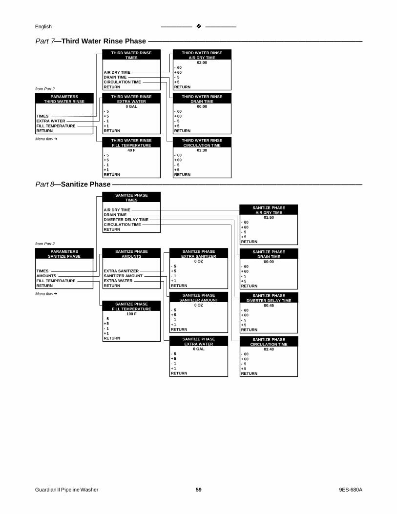
Guardian II Pipeline Washer 59 9ES-680A
English —————— v —————— Español
Part 7—Third Water Rinse Phase ——————————————————————————————
PARAMETERSTHIRD WATER RINSE
TIMESEXTRA WATERFILL TEMPERATURERETURN
from Part 2
THIRD WATER RINSEEXTRA WATER
0 GAL- 5+5- 1+1RETURN
THIRD WATER RINSEFILL TEMPERATURE
40 F- 5+5- 1+1RETURN
Menu flow ¢
THIRD WATER RINSETIMES
AIR DRY TIMEDRAIN TIMECIRCULATION TIMERETURN
THIRD WATER RINSEDRAIN TIME
00:00- 60+ 60- 5+ 5RETURN
THIRD WATER RINSEAIR DRY TIME
02:00- 60+ 60- 5+ 5RETURN
THIRD WATER RINSECIRCULATION TIME
03:30- 60+ 60- 5+ 5RETURN
Part 8—Sanitize Phase ———————————————————————————————————SANITIZE PHASE
TIMES
AIR DRY TIMEDRAIN TIMEDIVERTER DELAY TIMECIRCULATION TIMERETURN
SANITIZE PHASEDIVERTER DELAY TIME
00:45- 60+ 60- 5+ 5RETURN
SANITIZE PHASEDRAIN TIME
00:00- 60+ 60- 5+ 5RETURN
SANITIZE PHASECIRCULATION TIME
03:40- 60+ 60- 5+ 5RETURN
SANITIZE PHASEAIR DRY TIME
01:50- 60+ 60- 5+ 5RETURN
PARAMETERSSANITIZE PHASE
TIMESAMOUNTSFILL TEMPERATURERETURN
from Part 2
Menu flow ¢ SANITIZE PHASESANITIZER AMOUNT
0 OZ- 5+ 5- 1+ 1RETURN
SANITIZE PHASEEXTRA WATER
0 GAL- 5+ 5- 1+ 1RETURN
SANITIZE PHASEEXTRA SANITIZER
0 OZ- 5+ 5- 1+ 1RETURN
SANITIZE PHASEAMOUNTS
EXTRA SANITIZERSANITIZER AMOUNTEXTRA WATERRETURN
SANITIZE PHASEFILL TEMPERATURE
100 F- 5+5- 1+1RETURN

9ES-680A 60 Guardian II Limpiador de tuberías
English —————— v —————— Español
Part 9—Sanitize Water Rinse Phase —————————————————————————————
PARAMETERSSANITIZE WATER RINSE
TIMESEXTRA WATERFILL TEMPERATURERETURN
from Part 2
SANITIZE WATER RINSEEXTRA WATER
0 GAL- 5+5- 1+1RETURN
SANITIZE WATER RINSEFILL TEMPERATURE
40 F- 5+5- 1+1RETURN
Menu flow ¢
SANITIZE WATER RINSETIMES
AIR DRY TIMEDRAIN TIMECIRCULATION TIMERETURN
SANITIZE WATER RINSEDRAIN TIME
00:00- 60+ 60- 5+ 5RETURN
SANITIZE WATER RINSEAIR DRY TIME
02:00- 60+ 60- 5+ 5RETURN
SANITIZE WATER RINSECIRCULATION TIME
03:30- 60+ 60- 5+ 5RETURN
Part 10—Miscellaneous (System Setup) ———————————————————————————
SYSTEM SETUPDAIRY NAME
YOUR NAMESCROLL DOWNSCROLL UPÙ
Ú
RETURN
SYSTEM SETUPRS-232 BAUD RATE
960024001200600300RETURN
SYSTEM SETUPDISPLAY INTENSITY
160- 5+5- 1+1RETURN
SYSTEM SETUPTIME AND DATE
HISTORYDATETIMERETURN
MISCELLANEOUSSYSTEM SETUP
PRINT THE PARAMETERSDISPLAY INTENSITYDAIRY NAMERS-232 BAUD RATETIME AND DATERETURN
from Part 2
SYSTEM SETUPMONTH
01/01/1994- 5+ 5- 1+ 1RETURN
SYSTEM SETUPTIME12:00
- 5+ 5- 1+ 1RETURN
SYSTEM SETUPHISTORY
194 HOURS016 POWER FAILURES
PRESSÛ
SYSTEM SETUPDAY
01/01/1994- 5+ 5- 1+ 1RETURN
SYSTEM SETUPYEAR
01/01/1994- 5+ 5- 1+ 1RETURN
Menu flow ¢

Guardian II Pipeline Washer 61 9ES-680A
English —————— v —————— Español
UNITS/DEFAULTSSTANDARD SETUPS
SETUP 3SETUP 2SETUP 1RESET ALL DEFAULTSRETURN
UNITS/DEFAULTSDATE FORMAT
DD/MM/YYMM/DD/YY
UNITS/DEFAULTSTEMPERATURE UNITS
CELSIUSFAHRENHEIT
MISCELLANEOUSUNITS/DEFAULTS
STANDARD SETUPSDATE FORMATTEMPERATURE UNITSVOLUME UNITSLANGUAGERETURN
from Part 2
UNITS/DEFAULTSVOLUME UNITS
LITERS/MLGALLONS/OZ
UNITS/DEFAULTSLANGUAGE
ITALIANOESPANOLNEDERLANDSDEUTSCHFRANCAISENGLISH
Part 11—Miscellaneous (Units/Defaults) ——————————————————————————
Menu flow ¢
CONTROL VARIABLESPRINT FREQUENCY
6 TIMES/MIN- 5+ 5- 1+ 1RETURN
CONTROL VARIABLESPUMP DELAYS
SANITIZER PUMPACID PUMPDETERGENT PUMPRETURN
CONTROL VARIABLESFILL TEMP STABILITY
3 F- 5+ 5- 1+ 1RETURN
from Part 2
CONTROL VARIABLESFILL TIME LIMIT
20:00- 5+ 5- 1+ 1RETURN
CONTROL VARIABLESSINK CAPACITY
0 GAL- 5+ 5- 1+ 1RETURN
ACID PUMPDELAY TIME
01:00- 60+ 60- 5+ 5RETURN
SANITIZER PUMPDELAY TIME
01:00- 60+ 60- 5+ 5RETURN
DETERGENT PUMPDELAY TIME
00:30- 60+ 60- 5+ 5RETURN
Menu flow ¢
MISCELLANEOUSCONTROL VARIABLES
PRINT FREQUENCYPUMP DELAYSFILL TEMP STABILITYFILL TIME LIMITSINK CAPACITYRETURN
Part 12—Miscellaneous (Control Variables) —

9ES-680A 62 Guardian II Limpiador de tuberías
English —————— v —————— Español
from Part 2
Menu flow ¢
MISCELLANEOUSINPUTS/OUTPUTS
TEST MODEPLATE COOLER WATERTIMERSAUXILIARY OUTPUTSSENSORSRETURN
TEST MODE
AUXILIARY OUTPUTSMISC OUTPUTSRETURN
Part 13—Miscellaneous (Inputs/Outputs) ——————————————————————————
PLATE COOLER WATER
SANITIZE PHASESWASH PHASESRETURN
TIMER 3DELAY FROM END
02:00- 60+ 60- 5+ 5RETURN
TIMER 2DELAY FROM END
01:00- 60+ 60- 5+ 5RETURN
TIMER 1DELAY FROM END
01:00- 60+ 60- 5+ 5RETURN
TIMER 3ON TIME
45:00- 60+ 60- 5+ 5RETURN
TIMER 1DELAY FROM START
00:30- 60+ 60- 5+ 5RETURN
TIMER 2DELAY FROM START
00:30- 60+ 60- 5+ 5RETURN
PLATE COOLER WATERSANITIZE WATER RINSE
COLDWARMHOTWATER OFF
PLATE COOLER WATERACID PHASE
COLDWARMHOTWATER OFF
PLATE COOLER WATERSECOND WATER RINSE
COLDWARMHOTWATER OFF
PLATE COOLER WATERTHIRD WATER RINSE
COLDWARMHOTWATER OFF
PLATE COOLER WATERFIRST WATER RINSE
COLDWARMHOTWATER OFF
PLATE COOLER WATERDETERGENT PHASE
COLDWARMHOTWATER OFF
AUXILIARY OUTPUTSAUXILIARY 6AUXILIARY 5AUXILIARY 4AUXILIARY 3AUXILIARY 2AUXILIARY 1RETURN
MISC OUTPUTS
VACUUMDIVERTERDRAINHOT WATERCOLD WATERRETURN
PLATE COOLER WATERWASH PHASES
THIRD WATER RINSEACID PHASESECOND WATER RINSEDETERGENT PHASEFIRST WATER RINSERETURN
PLATE COOLER WATERSANITIZE PHASES
SANITIZE WATER RINSESANITIZE PHASERETURN
PLATE COOLER WATERSANITIZE PHASE
COLDWARMHOTWATER OFF
SENSORS
MILK/WASH SWITCHMILKLINE POSITION SWTEMPERATURERETURN
MILKLINE POSITION SWINSTALLED?
NOYES
TEMPERATURESENSOR INSTALLED?
NOYES
MILK/WASH SWITCHINSTALLED?
NOYES
TIMERS
TIMER 3TIMER 2TIMER 1RETURN
AUXILIARY OUTPUTSAUXILIARY 6AUXILIARY 5AUXILIARY 4AUXILIARY 3AUXILIARY 2AUXILIARY 1RETURN
AUXILIARY #
MORECOLD PC OUTPUTBOOSTER OUTPUTALARM OUTPUTREMOTE OUTPUTCYCLE ON OUTPUT
AUXILIARY #
PREVIOUS MENUTIMER 3TIMER 2TIMER 1HOT PC OUTPUT
TIMER 2FIRST RINSE + DETER
DELAY FROM ENDDELAY FROM STARTRETURN
TIMER 1FOR EACH PHASE
DELAY FROM ENDDELAY FROM STARTRETURN
TIMER 3FOR EACH PHASE
ON TIMEDELAY FROM ENDRETURN

Guardian II Pipeline Washer 63 9ES-680A
English —————— v —————— Español
Part 14—Miscellaneous (Calibrations) ———————————————————————————
TEMPERATURE SENSORCORRECTION
0 F- 5+5- 1+1RETURN
MISCELLANEOUSCALIBRATIONS
TEMPERATURE SENSORVIEW PUMP FLOW RATECHEMICAL PUMPSRETURN
from Part 2
VIEW PUMP FLOW RATE
SANITIZERACIDDETERGENTRETURN
ACIDPUMP FLOW RATE
22 OZ/MIN- 5+ 5- 1+ 1RETURN
DETERGENTPUMP FLOW RATE
22 OZ/MIN- 5+ 5- 1+ 1RETURN
SANITIZERPUMP FLOW RATE
22 OZ/MIN- 5+ 5- 1+ 1RETURN
CALIBRATESANITIZER PUMP
00:15 00:15 DELAY
00:0101 OZ
STOP
CALIBRATEACID PUMP
00:15 00:15 DELAY
00:0101 OZ
STOP
CALIBRATECHEMICAL PUMPS
SANITIZER PUMPACID PUMPDETERGENT PUMPRETURN
ENTER AMOUNTDISPENSED
22 OZ-5+5-1+1
RETURN
Menu flow ¢
CALIBRATEDETERGENT PUMP00:15 00:15 DELAY
00:0101 OZ
STOP

9ES-680A 64 Guardian II Limpiador de tuberías
English —————— v —————— Español
7. Estructura del Menú
INICIO FASES MANUALES
FASES DESINFECTANTESFASES LAVADOREGRESAR
ESTABLECER PROXIMOLAVADO
CICLO LAVADO 5CICLO LAVADO 4CICLO LAVADO 3CICLO LAVADO 2CICLO LAVADO 1REGRESAR
INICIO FASES MANUALESFASES DE LAVADO
TERCER ACL... CON AGUAFASE ACIDOSEGUNDO ACL... CON AGUAFASE DETERGENTEPRIMER ACL... CON AGUAREGRESAR
DINICIO FASES MANUALESFASES DESINFECTANTES
ACL... CON AGUA Y DESINFFASE DESINFECTANTEREGRESAR
CANTIDAD A DISPENSARACIDO0 OZ
-5+5-1+1REGRESAR
CANTIDAD A DISPENSARDETERGENTE
0 OZ-5+5-1+1REGRESAR
CANTIDAD A DISPENSARDESINFECTANTE
0 OZ-5+5-1+1REGRESAR
DISTRIBUCION MANUALCANTIDAD A DISPENSAR
DESINFECTANTEACIDODETERGENTEREGRESAR
DISTRIBUCION MANUALDETERGENTE
00:15 —> 00:15 RETRAS..
00:01
00 OZPARADA
DISTRIBUCION MANUAL
CANTIDAD A DISPENSARBOMBA DESINFECCIONBOMBA ACIDOBOMBA DETERGENTEREGRESAR
DISTRIBUCION MANUALDESINFECTANTE
00:15 —> 00:15 RETRAS..
00:01
00 OZPARADA
DISTRIBUCION MANUALACIDO
00:15 —> 00:15 RETRAS..
00:01
00 OZPARADA
LISTO
OPCIONES
INICIO LAVCICLO 1
Menú principalLa estructura del menú sedesarrolla de izquierda aderecha ¢
ver parte 2OPCIONES
PARAMETROSINICIO FASES MANUALESINICIO LAVADO SIGUIENTEINICIO CICLO DESINFECTANINICIO CICLO DESINFECTANREGRESAR

Guardian II Pipeline Washer 65 9ES-680A
English —————— v —————— Español
Parte 2—Parámetros ———————————————————————————————————
CICLO DESINFECCIONTIEMPO INICIO
TERCERA DESINFECCIONSEGUNDA DESINFECCIONPRIMERA DESINFECCIONREGRESAR
PARAMETROS
MISCELANEOSTIEMPO DE INICIO DESINFCONTENIDOS CICLOESTABLECIMIENTO FASEREGRESAR
viene de la parte 1
PARAMETROSMISCELANEOS
CALIBRACIONESINPUTS/OUTPUTSVARIABLES DE CONTROLUNIDADES/FALLOSESTABLECIMIENTO SISTEMAREGRESAR
ver parte 14ver parte 13ver parte 12ver parte 11ver parte 10
INICIO TIEMPOTERCERA DESINFECCION
00:00- 5+ 5- 1+ 1REGRESAR
INICIO TIEMPOSEGUNDA DESINFECCION
00:00- 5+ 5- 1+ 1REGRESAR
INICIO TIEMPOTERCERA DESINFECCION
00:00- 5+ 5- 1+ 1REGRESAR
PARAMETROSFASES DE LAVADO
TERCER ACL... CON AGUAFASE ACIDOSEGUNDO ACL... CON AGUAFASE DETERGENTEPRIMER ACL... CON AGUAREGRESAR
ver parte 7ver parte 6ver parte 5ver parte 4ver parte 3
PARAMETROSESTABLECIMIENTO FASE
FASES DESINFECCIONFASES LAVADOREGRESAR
CONTENIDOS DEL CICLOCICLO DESINFECCIONCICLO DE LAVADO 5CICLO DE LAVADO 4CICLO DE LAVADO 3CICLO DE LAVADO 2CICLO DE LAVADO 1REGRESAR
ACL... DE AGUA Y DESINF¿CAPACITADO?
NOSI
FASE ACIDO¿CAPACITADO?
NOSI
TERCER ACL... CON AGUA¿CAPACITADO?
NOSI
SEGUNDO ACL.. CON AGUA¿CAPACITADO?
NOSI
PRIMER ACL... CON AGUA¿CAPACITADO?
NOSI
FASE DETERGENTE¿CAPACITADO?
NOSI
ver parte 9ver parte 8
el menu se desarrolla enesta direccion ¢
ESTABLE... DEL CICLONUMERO CICLO LAVADO
TERCER ACL... CON AGUAFASE ACIDOSEGUNDO ACL... CON AGUAFASE DETERGENTEPRIMER ACL... CON AGUAREGRESAR
PARAMETROSFASES DEINFECCION
ACL... CON AGUA Y DESINFFASE DESINFECTANTEREGRESAR

9ES-680A 66 Guardian II Limpiador de tuberías
English —————— v —————— Español
Parte 4—Fase detergente —————————————————————————————————
FASE DETERGENTETEMPERATURAS
TEMP. PARADA CIRC.TEMP ALARMA LLENADOTEMPERATURA LLENADOREGRESAR
PARAMETROSFASE DETERGENTE
TIEMPOCANTIDADESTEMPERATURASREGRESAR
viene de la parte 2
FASE DETERGENTETEMP. PARADA CIRC.
115 F- 5+ 5- 1+ 1REGRESAR
FASE DETERGENTETEMP. ALARMA LLENADO
160 F- 5+ 5- 1+ 1REGRESAR
FASE DETERGENTETIEMPO DE SECA.. C.. AIRETIEMPO DRENAJETIEMPO RETRASO DESVIOCIRC. TIEMPO ALARMACIRC. TIEMPO MINIMOTIEMPO CIRCULACIONREGRESAR
FASE DETERGENTECANTIDAD CLORO
0 OZ- 5+ 5- 1+ 1REGRESAR
FASE DETERGENTEDETERGENTE EXTRA
0 OZ- 5+ 5- 1+ 1REGRESAR
FASE DETERGENTECLORO EXTRA
0 OZ- 5+ 5- 1+ 1REGRESAR
FASE DETERGENTECANTIDAD DETERGENTE
5 OZ- 5+ 5- 1+ 1REGRESAR
FASE DETERGENTEAGUA EXTRA
0 GAL- 5+ 5- 1+ 1REGRESAR
FASE DETERGENTECANTIDADES
CLORO EXTRACANTIDAD CLORODTERGENTE EXTRACANTIDAD DETERGENTEAGUA EXTRAREGRESAR
FASE DETERGENTETIEMPO DRENAJE
00:00- 60+ 60- 5+ 5REGRESAR
FASE DETERGENTETIEMPO SECADO C.. AIRE
01:50- 60+ 60- 5+ 5REGRESAR
FASE DETERGENTETIEMPO RETRASO DESVIO
00:45- 60+ 60- 5+ 5REGRESAR
FASE DETERGENTETIEMPO ALARMA CIRC.
05:00- 60+ 60- 5+ 5REGRESAR
FASE DETERGENTETIEMPO MINIMO CIRC.
04:00- 60+ 60- 5+ 5REGRESAR
FASE DETERGENTETIEMPO CIRCULACION
09:00- 60+ 60- 5+ 5REGRESAR
viene de la parte 2
PRIMER ACL... CON AGUAAGUA EXTRA
0 GAL- 5+5- 1+1REGRESAR
PRIMER ACL... C.. AGUATEMP. DE LLENADO
105 F- 5+5- 1+1REGRESAR
PRIMER ACL... CON AGUATIEMPO DRENAJE
00:00- 60+ 60- 5+ 5REGRESAR
PRIMER ACL... CON AGUATIEMPO DE SECA.. C.. AIRE
02:00- 60+ 60- 5+ 5REGRESAR
PRIMER ACL... CON AGUATIEMPO CIRCULACION
03:30- 60+ 60- 5+ 5REGRESAR
el menu se desarrolla enesta direccion ¢
Parte 3—Fase del primer aclarado de agua ——————————————————————————
FASE DETERGENTETEMPERATURA LLENADO
185 F- 5+ 5- 1+ 1REGRESAR
el menu se desarrolla enesta direccion ¢
PRIMER ACL... CON AGUATIEMPO
TIEMPO DE SECADO C.. AGUATIEMPO DRENAJETIEMPO CIRCULACIONREGRESAR
PARAMETROSPRIMER ACL... CON AGUA
TIEMPOAGUA EXTRATEMPERATURA DE LLENADOREGRESAR

Guardian II Pipeline Washer 67 9ES-680A
English —————— v —————— Español
Parte 5—Fase del segundo aclarado con agua ————————————————————————
PARAMETROSSEGUNDO ACL... CON AGUA
TIEMPOAGUA EXTRATEMP. DE LLENADOREGRESAR
viene de la parte 2
SEGUNDO ACL... C.. AGUAAGUA EXTRA
0 GAL- 5+5- 1+1REGRESAR
SEGUNDO ACL... C.. AGUATEMPERATURA LLENADO
40 F- 5+5- 1+1REGRESAR
SEGUNDO ACL... CON AGUATIEMPO
TIEMPO SECADO CON AIRETIEMPO DRENAJETIEMPO CIRCULACIONREGRESAR
SEGUNDO ACL... CON AGUATIEMPO DRENAJE
00:00- 60+ 60- 5+ 5REGRESAR
SEGUNDO ACL... CON AGUATIEMPO SECADO CON AIRE
02:00- 60+ 60- 5+ 5REGRESAR
SEGUNDO ACL... CON AGUATIEMPO CIRCULACION
03:30- 60+ 60- 5+ 5REGRESAR
Parte 6—Fase del ácido ——————————————————————————————————
FASE ACIDOTIEMPO SECADO C.. AIRETIEMPO DRENAJETIEMPO RETRASO DESVIOTIEMPO ALRMA CIRC.TIEMPO MINIMO CIRC.TIEMPO CIRCULACIONREGRESAR
FASE ACIDOTIEMPO RETRASO DESVIO
00:00- 60+ 60- 5+ 5REGRESAR
FASE ACIDOTIEMPO DRENAJE
01:50- 60+ 60- 5+ 5REGRESAR
FASE ACIDOTIEMPO ALARMA CIRC.
00:45- 60+ 60- 5+ 5REGRESAR
FASE ACIDOTIEMPO MINIMO CIRC.
00:00- 60+ 60- 5+ 5REGRESAR
FASE ACIDOTIEMPO CIRCULACION
04:00- 60+ 60- 5+ 5REGRESAR
FASE ACIDOTIEMPO CIRCULACION
04:30- 60+ 60- 5+ 5REGRESAR
PARAMETROSFASE ACIDO
TIEMPOCANTIDADESTEMPERATURASREGRESAR
viene de la parte 2
FASE ACIDOACIDO EXTRA
0 OZ- 5+ 5- 1+ 1REGRESAR
FASE ACIDOCANTIDAD ACIDO
0 OZ- 5+ 5- 1+ 1REGRESAR
FASE ACIDOAGUA EXTRA
0 GAL- 5+ 5- 1+ 1REGRESAR
FASE ACIDO
CANTIDADESACIDO EXTRACANTIDAD DE ACIDOAGUA EXTRAREGRESAR
FASE ACIDOTEMP. PARADA CIRC.
35 F- 5+ 5- 1+ 1REGRESAR
FASE ACIDOTEMP. ALARMA LLEN..
35 F- 5+ 5- 1+ 1REGRESAR
FASE ACIDOTEMP. ALARMA LLEN..
40 F- 5+ 5- 1+ 1REGRESAR
FASE ACIDOTEMPERATURAS
TEMP. PARADA CIRC.TEMP. ALARMA LLENADOTEMPERATURA LLENADOREGRESAR
el menu se desarrolla enesta direccion ¢
el menu se desarrolla enesta direccion ¢

9ES-680A 68 Guardian II Limpiador de tuberías
English —————— v —————— Español
Parte 7—Tercer aclarado con agua —————————————————————————————
PARAMETROSTERCER ACL... CON AGUA
TIEMPOAGUA EXTRATEMPERATURA DE LLENADOREGRESAR
viene de la parte 2
TERCER ACL... CON AGUAAGUA EXTRA
0 GAL- 5+5- 1+1REGRESAR
TERCER ACL... CON AGUATEMP. DE LLENADO
40 F- 5+5- 1+1REGRESAR
TERCER ACL... C.. AGUATIEMPOS
TIEMPO SECADO CON AIRETIEMPO DRENAJETIEMPO CIRCULACIONREGRESAR
TERCER ACLAR.. C.. AGUATIEMPO DRENAJE
00:00- 60+ 60- 5+ 5REGRESAR
TTERCER ACLAR.. C.. AGUATIEMPO DE SECA.. C.. AIRE
02:00- 60+ 60- 5+ 5REGRESAR
TERCER ACLAR.. C.. AGUATIEMPO CIRCULACION
03:30- 60+ 60- 5+ 5REGRESAR
Parte 8—Fase desinfectante ————————————————————————————————FASE DESINFECTANTE
TIEMPO
TIEMPO SECADO CON AIRETIEMPO DRENAJETIEMPO RETRASO DESVIOTIEMPO CIRCULACIONREGRESAR
FASE DESINFECTANTETIEMPO RETRASO DESVIO
00:45- 60+ 60- 5+ 5REGRESAR
FASE DESINFECTANTETIEMPO DRENAJE
00:00- 60+ 60- 5+ 5REGRESAR
FASE DESINFECTANTETIEMPO CIRCULACION
03:40- 60+ 60- 5+ 5REGRESAR
FASE DESINFECTANTETIEMPO SEC.. C.. AIRE
01:50- 60+ 60- 5+ 5REGRESAR
PARAMETROSFASE DESINFECTANTE
TIEMPOCANTIDADESTEMPERATURA LLENADOREGRESAR
viene de la parte 2
FASE DESINFECTANTECANTIDAD DESINFECTANTE
0 OZ- 5+ 5- 1+ 1REGRESAR
FASE DESINFECTANTEAGUA EXTRA
0 GAL- 5+ 5- 1+ 1REGRESAR
FASE DESINFECTANTEDESINFECTANTE EXTRA
0 OZ- 5+ 5- 1+ 1REGRESAR
FASE DESINFECTANTECANTIDADES
DESINFECTANTE EXTRACANTIDAD DESINFECTANTEAGUA EXTRAREGRESAR
FASE DESINFECTANTETEMPERATURA LLENADO
100 F- 5+5- 1+1REGRESAR
el menu se desarrolla enesta direccion ¢
el menu se desarrolla enesta direccion ¢

Guardian II Pipeline Washer 69 9ES-680A
English —————— v —————— Español
Parte 9—Fase de aclarado con agua y desinfectante —————————————————————
PARAMETROSFAS D AC... C.. AGUA . DSINF
TIEMPOAGUA EXTRATEMPERATURA LLENADOREGRESAR
viene de la parte 2
FAS D AC... C.. AGUA . DSINFAGUA EXTRA
0 GAL- 5+5- 1+1REGRESAR
FAS D AC... C.. AGUA . DSINFTEMPERATURA LLENADO
40 F- 5+5- 1+1REGRESAR
FAS D AC... C.. AGUA . DSINFTIEMPO
TIEMPO SECADO CON AIRETIEMPO DRENAJETIEMPO CIRCULACIONREGRESAR
FAS D AC... C.. AGUA . DSINFTIEMPO DRENAJE
00:00- 60+ 60- 5+ 5REGRESAR
FAS D AC... C.. AGUA . DSINFTIEMPO SECADO CON AIRE
02:00- 60+ 60- 5+ 5REGRESAR
FAS D AC... C.. AGUA . DSINFTIEMPO CIRCULACION
03:30- 60+ 60- 5+ 5REGRESAR
Parte 10—Miscelaneos (establecimiento del sistema) ————————————————————
ESTABLECI.. DEL SISTEMANOMBRE GRANJA
SU NOMBREDESENROLLARENROLLARÙ
Ú
REGRESAR
ESTABLECI.. DEL SISTEMATASA BAUDIO RS-232
960024001200600300REGRESAR
ESTABLECI.. DEL SISTEMALUMINOSIDAD PANTALLA
160- 5+5- 1+1REGRESAR
ESTABLECI.. DEL SISTEMAHORA Y FECHA
HISTORIAFECHAHORAREGRESAR
MISCELANEOSESTABLECI.. DEL SISTEMA
IMPRESION DE PARAMETROSLUMINOSIDAD DE PANTALLANOMBRE GRANJATASA BAUDIO RS-232HORA Y FECHAREGRESAR
viene de la parte 2
ESTABLECI.. DEL SISTEMAMES
01/01/1994- 5+ 5- 1+ 1REGRESAR
ESTABLECI.. DEL SISTEMAHORA12:00
- 5+ 5- 1+ 1REGRESAR
ESTABLECI... DEL SISTEMAHISTORIA
194 HORAS016 FALLOS DE ENERGIA
REGRESARÛ
ESTABLECI... DEL SISTEMADIA
01/01/1994- 5+ 5- 1+ 1REGRESAR
ESTABLECI... DEL SISTEMAAÑO
01/01/1994- 5+ 5- 1+ 1REGRESAR
el menu se desarrolla enesta direccion ¢
el menu se desarrolla enesta direccion ¢

9ES-680A 70 Guardian II Limpiador de tuberías
English —————— v —————— Español
UNIDADES/FALLOSPARAMETROS ESTANDARD
PARAMETRO 3PARAMETRO 2PARAMETRO 1RESITUAR TODOS L.. FALLOSREGRESAR
UNIDADES/FALLOSFORMATO FECHA
DIA/MES/AÑOMES/DIA/AÑO
UNIDADES/FALLOSUNIDADES TEMPERATURA
CELSIUSFAHRENHEIT
MISCELANEOSUNIDADES/FALLOS
PARAMETROS ESTANDARDFORMATO FECHAUNIDADES TEMPERATURAUNIDADES VOLUMENLENGUAREGRESAR
viene de la parte 2
UNIDADES/FALLOSUNIDADES VOLUMEN
LITROS/MLGALONES/OZ
UNIDADES/FALLOSLENGUA
ITALIANOESPAÑOLNEDERLANDSDEUTSCHFRANÇAISENGLISH
Parte 11—Misceláneos (Unidades/Fallos) ——————————————————————————
VARIABLES DE CONTROLFRECUENCIA DE IMPRESION
6 NOMBRE/MIN- 5+ 5- 1+ 1REGRESAR
VARIABLES DE CONTROLRETRASOS BOMBA
BOMBA DESINFECTANTEBOMBA ACIDOBOMBA DETERGENTEREGRESAR
VARIABLES DE CONTROLESTABIL.. TEMP. LLENADO
3 F- 5+ 5- 1+ 1REGRESAR
viene de la parte 2
VARABLES DE CONTROLLIMITE TIEMPO LLENADO
20:00- 60+ 60- 5+ 5REGRESAR
VARIABLES DE CONTROLCAPACIDAD TANQUE
0 GAL- 5+ 5- 1+ 1REGRESAR
BOMBA ACIDOTIEMPO RETRASO
01:00- 60+ 60- 5+ 5REGRESAR
BOMBA DESINFECTANTETIEMPO RETRASO
01:00- 60+ 60- 5+ 5REGRESAR
BOMBA DETERGENTETIEMPO RETRASO
00:30- 60+ 60- 5+ 5REGRESAR
MISCELANEOSVARIABLES DE CONTROL
FRECUENCIA DE IMPRESIONRETRASOS DE LA BOMBAESTABIL.. TEMP. LLENADOLIMITE TIEMPO LLENADOCAPACIDAD TANQUEREGRESAR
Parte 12—Misceláneos (Variables de control)—
el menu se desarrolla enesta direccion ¢
el menu se desarrolla enesta direccion ¢

Guardian II Pipeline Washer 71 9ES-680A
English —————— v —————— Español
viene de la parte 2
MISCELANEOSINPUTS/OUTPUTS
MODO DE PRUEBAPLACA REFRIGERANTE AGUARELOJESOUTPUTS AUXILIARESSENSORESREGRESAR
MODO DE PRUEBA
OUTPUTS AUXILIARESOUTPUTS MISC.REGRESAR
Parte 13—Misceláneos (inputs/outputs) ———————————————————————————
PLACA REFRIGERANTEAGUA
FASES DESINFECCIONFASES LAVADOREGRESAR
RELOJ 3RETRASO DEL FINAL
02:00- 60+ 60- 5+ 5REGRESAR
RELOJ 2RETRASO DEL FINAL
01:00- 60+ 60- 5+ 5REGRESAR
RELOJ 1RETRASO DEL FINAL
01:00- 60+ 60- 5+ 5REGRESAR
RELOJ 3A PUNTO
45:00- 60+ 60- 5+ 5REGRESAR
RELOJ 1RETRASO DEL INICIO
00:30- 60+ 60- 5+ 5REGRESAR
RELOJ 2RETRASO DEL INICIO
00:30- 60+ 60- 5+ 5REGRESAR
PLACA REFRIGER. AGUAACLARADO AGUA Y DESINF.
FRIATEMPLADACALIENTEAGUA CORTADA
PLACA REFRIGER.. AGUAFASE ACIDO
FRIATEMPLADACALIENTEAGUA CORTADA
PLACA REFRIGER.. AGUASEGUNDO ACLAR.. C.. AGUA
FRIATEMPLADACALIENTEAGUA CORTADA
PLACA REFRIGER.. AGUATERCER ACLAR.. CON AGUA
FRIATEMPLADACALIENTEAGUA CORTADA
PLACA REFRIGER.. AGUAPRIMER ACLAR.. C.. AGUA
FRIATEMPLADACALIENTEAGUA CORTADA
PLACA REFRIGER.. AGUAFASE DETERGENTE
FRIATEMPLADACALIENTEAGUA CORTADA
OUTPUTS AUXILIARESAUXILIAR 6AUXILIAR 5AUXILIAR 4AUXILIAR 3AUXILIAR 2AUXILIAR 1REGRESAR
MODO DE PRUEBAOUTPUTS MISC.
VACIADODESVIODRENAJEAGUA CALIENTEAGUA FRIAREGRESAR
PLACA REFRIGERANTE AGUAFASES DESINFECCIÓN
FAS D AC...C...AGUA.DSINFFASE LAVADOREGRESAR
PLACA REFRIGER AGUAFASE DESINFECTANTE
FRIATEMPLADACALIENTEAGUA CORTADA
SENSORES
INTER. ORDEÑO/LAVADOINTER. POSI. TUBO LECHETEMPERATURAREGRESAR
INTER. POSI. TUBO LECHE¿INSTALADO?
NOSI
TEMPERATURA¿SENSOR INSTALADO?
NOSI
INTER. ORDEÑO/LAVADO¿INSTALADO?
NOSI
RELOJES
RELOJ 3RELOJ 2RELOJ 1REGRESAR
OUTPUTS AUXILIARESAUXILIAR 6AUXILIAR 5AUXILIAR 4AUXILIAR 3AUXILIAR 2AUXILIAR 1REGRESAR
NUMERO DEL AUXILIAR #
MASOUTPUT DE LA PLACA FRIAOUTPUT REFORZADOROUTPUT ALARMAOUTPUT DISTANCIAOUTPUT CICLO ENCENDIDO
NUMERO DEL AUXILIAR #
MENU PREVIORELOJ 3RELOJ 2RELOJ 1OUTPUT PLACA CALIENTE
RELOJ 2PRIMER ACLAR+DETERG
RETRASO DEL FINALRETRASO DEL INICIOREGRESAR
RELOJ 1PARA CADA FASE
RETRASO DEL FINALRETRASO DEL INICIOREGRESAR
RELOJ 3PARA CADA FASE
A TIEMPORETRASO DEL FINALREGRESAR
el menu se desarrolla enesta direccion ¢
PLACA REFRIGERANTE FRIAFASES LAVADO
TERCER ACL.. CON AGUAFASE ACIDOSEGUNDO ACL.. CON AGUAFASE DETERGENTEPRIMER ACL.. CON AGUAREGRESAR

9ES-680A 72 Guardian II Limpiador de tuberías
English —————— v —————— Español
Parte 14—Misceláneos (Calibraciones) ———————————————————————————
SENSOR TEMPERATURACORRECCION
0 F- 5+5- 1+1REGRESAR
MISCELANEOSCALIBRACIONES
SENSOR TEMPERATURAVISTA CAUDAL BOMBABOMBAS SUSTANC QUIMICASREGRESAR
viene de la parte 2
VISTA CAUDAL BOMBA
DESINFECTANTEACIDODETERGENTEREGRESAR
ACIDOCAUDAL BOMBA
22 OZ/MIN- 5+ 5- 1+ 1REGRESAR
CALIBRARBOMBA DESINFECTANTE
22 OZ/MIN- 5+ 5- 1+ 1REGRESAR
DESINFECTANTECAUDAL BOMBA
22 OZ/MIN- 5+ 5- 1+ 1REGRESAR
CALIBRARBOMBA ...
00:15 00:15 RETRASO
00:0101 OZ
PARADA
CALIBRARBOMBA ACIDO
00:15 00:15 RETRASO
00:0101 OZ
PARADA
CALIBRARBOMBAS SUSTANC
QUIMICAS
BOMBA ACIDOBOMBA DETERGENTEREGRESAR
INTRODUCIR CANTIDADDISPENSADA
22 OZ-5+5-1+1
REGRESAR
CALIBRARBOMBA DETERGENTE00:15 00:15 RETRASO
00:0101 OZ
PARADA
el menu se desarrolla enesta direccion ¢