guida all’installazione installation guide ... · d749ma 1 guida all’installazione installation...
TRANSCRIPT

1D749MA
GUIDA ALL’INSTALLAZIONEINSTALLATION GUIDE
INSTALLATIONSANLEITUNGNOTICE D’INSTALLATION
GUÍA PARA LA INSTALACIÓNGUIA DE INSTALAÇÃO
D749MAQuadro di comando per uno/due motori 18V con encoder
Control panel for one-two 18V motors with encoderSteuerplatine für einen (zwei) 18V Motor(en) mit Encoder
Logique de commande pour un ou deux moteurs 18V avec encodeurPanel de mandos para uno or dos motores 18V con encoder
Quadro de comando para um ou dois motores de 18V com encoder
Via Enrico Fermi, 43 - 36066 Sandrigo (VI) ItaliaTel +39 0444 750190 - Fax +39 0444 750376
[email protected] - www.tauitalia.com
IT - Istruzioni originali
D-M
NL0
D7
49
MA
24-0
1-2
014 -
Rev.0
3

2 D749MA
SCHEMA CABLAGGIO D749MA / D749MA WIRING DIAGRAM / SCHALTPLAN DER
TRA
FR
TCA
CH2
PROG
CH1
F4
16A
F3
2A
F5
10A
DL6
DL5
DL4
DL3
DL2
DL1
DL8
DL7
1 2 3 4 5 6 7 8 9 10 11 12
1 2 3 4 5 6 7 8 9 10 11 12
D749MA
Dip-switchesON
DL6
DL5
DL4
DL3
DL2
DL1
DL8
FIXED SAFETY EDGE
EXT. PHOTO
INT. PHOTO
STOP
OPEN/CLOSE
PEDESTRIAN
ERRORS
DL7 BATT
TCA
+-
FR
+-
TRA
+-
TR
1
2
3
4
5
6
7
8
9
1
1
1
1
1
1
1
1
1
1
2
2
2
23242526272829303132
- +M
1
+5V
EN
C
GN
D
- +M
2
+5V
EN
C
GN
D
J6
Power supply
by transformer
J7
External
power supply

3D749MA
D749MA / SCHÉMA CÂBLAGE D749MA / ESQUEMA DEL CABLEADO D749MA
H2
PROG
H1
F3
2A
FS1
TRASF
FS2
1
2
3
4
5
6
7
8
9
10
11
12
13
14
15
16
17
18
19
20
21
22
Flashing
light
18V DC
max. 20W
Open/Close
-
+ 18 V
-
+ 18 V
-
Stop
Common
Common
Pedestrian
- Input aux
+ Input aux
Int. Photocell
Gate open
warning light
max. 3W
2nd radio
channel
Aerial
Fixed safety edge
-
+ 18 V
-
Ext. Photocell
Common
External
Photocells
RX
1 2 3 4 5
TX
1 2
-
+
BATT
J6
Internal
PhotocellsRX
1 2 3 4 5
TX
1 2
E.L.
18V 15W
Morsetti 1 - 2: Attenzione a NON invertire la polaritàTerminals 1 – 2: Careful NOT to invert polarity.Klemmen 1 - 2: Achtung: Nicht verpolen.Etaux 1 - 2: Assurez-vous de NE PAS inverser la polarité.Bornes 1 - 2: Tenga cuidado en NO invertir la polaridad.Terminais 1 – 2: Cuidado NÂO inverter a polaridade.

15D749MA
MANUFACTURER’S DECLARATION OF INCORPORATION(in accordance with European Directive 2006/42/EC App. II.B)
Manufacturer: TAU S.r.l.
Address: Via E. Fermi, 43
36066 Sandrigo (Vi)
ITALY
Declares under its sole responsibility, that the product: Electronic control unit
designed for automatic movement of: Swing Gates
for use in a: Residential / Communities
complete with: Radioreceiver and battery charger board
Model: D749MA
Type: D749MA
Serial number: see silver label
Commercial name: Control panel for one-two 12V motors with en-
coder
Has been produced for incorporation on an access point (swing gate) of for assembly with other devices used to
move such an access point, to constitute a machine in accordance with the Machinery Directive 2006/42/EC.
Also declares that this product complies with the essential safety requirements of the following EEC directives:
- 2006/95/EC Low Voltage Directive
- 2004/108/EC Electromagnetic Compatibility Directive
and, where required, with the Directive:
- 1999/5/CE Radio equipment and telecommunications terminal equipment
Also declares that it is not permitted to start up the machine until the machine in which it is incorporated or of
which it will be a component has been identiied with the relative declaration of conformity with the provisions of Directive 2006/42/EC.
The manufacturer undertakes to provide, on suficiently motivated request by national authorities, all information pertinent to the quasi-machinery.
Sandrigo, 20/03/2013
Legal Representative
_________________________________________
Bruno Danieli
Name and address of person authorised to draw up all pertinent technical documentation:
Loris Virgilio Danieli - via E. Fermi, 43 - 36066 Sandrigo (Vi) Italy
EN
GLIS
H
16 D749MA
WARNINGSThis manual is designed to assist qualiied installation personnel only. It contains no informa-
tion that may be of interest to inal users. This manual is attached to the D749MA control unit, therefore it may not be used for different products!
Important warnings:Disconnect the mains power supply to the board before accessing it.The D749MA control unit is suitable for the control of a direct-current electromechanical gearmo-
tor for automating gates and doors of all kinds.Any other use is considered improper and is consequently forbidden by current laws.
Please note that the automation system you are going to install is classii ed as “machine con-
struction” and therefore is included in the application of European directive 2006/42/EC (Ma-
chinery Directive).
This directive includes the following prescriptions:
- Only trained and qualiied personnel should install the equipment;- the installer must irst make a “risk analysis” of the machine;- the equipment must be installed in a correct and workmanlike manner in compliance with all
the standards concerned;- after installation, the machine owner must be given the “declaration of conformity”.This product may only be installed and serviced by qualiied personnel in compliance with cur-rent, laws, regulations and directives.
When designing its products, TAU observes all applicable standards (please see the attached declaration of conformity) but it is of paramount importance that installers strictly observe the
same standards when installing the system.
Unqualiied personnel or those who are unaware of the standards applicable to the “automatic gates and doors” category may not install systems under any circumstances.
Whoever ignores such standards shall be held responsible for any damage caused by the system!Do not install the unit before you have read all the instructions.
INSTALLATIONBefore proceeding, make sure the mechanical components work correctly. Also check that the gear motor assembly has been installed according to the instructions. Then make sure that the power consumption of the gear motor is not greater than 3A (other-wise the control panel may not work properly).THE EQUIPMENT MUST BE INSTALLED “EXPERTLY” BY QUALIFIED PERSONNEL AS RE-
QUIRED BY LAW.Note: it is compulsory to earth the system and to observe the safety regulations that are in force in each country.IF THESE ABOVE INSTRUCTIONS ARE NOT FOLLOWED IT COULD PREJUDICE THE PROPER WORKING ORDER OF THE EQUIPMENT AND CREATE HAZARDOUS SITUA-
TIONS FOR PEOPLE. FOR THIS REASON THE “MANUFACTURER” DECLINES ALL RE-
SPONSIBILITY FOR ANY MALFUNCTIONING AND DAMAGES THUS RESULTING.
EN
GLIS
H
17D749MA
EN
GLIS
H
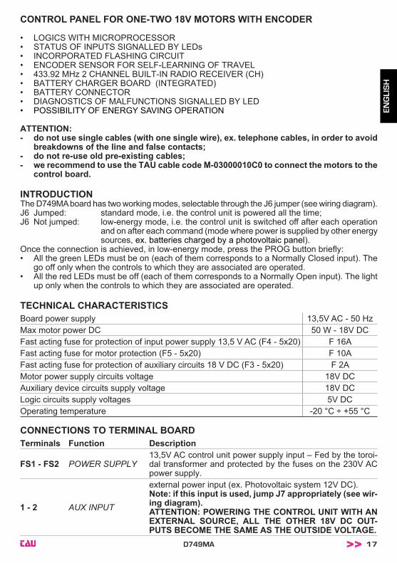
CONTROL PANEL FOR ONE-TWO 18V MOTORS WITH ENCODER
• LOGICS WITH MICROPROCESSOR• STATUS OF INPUTS SIGNALLED BY LEDs• INCORPORATED FLASHING CIRCUIT• ENCODER SENSOR FOR SELF-LEARNING OF TRAVEL • 433.92 MHz 2 CHANNEL BUILT-IN RADIO RECEIVER (CH)• BATTERY CHARGER BOARD (INTEGRATED)• BATTERY CONNECTOR• DIAGNOSTICS OF MALFUNCTIONS SIGNALLED BY LED• POSSIBILITY OF ENERGY SAVING OPERATION
ATTENTION:- do not use single cables (with one single wire), ex. telephone cables, in order to avoid
breakdowns of the line and false contacts;- do not re-use old pre-existing cables;- we recommend to use the TAU cable code M-03000010C0 to connect the motors to the
control board.
INTRODUCTION The D749MA board has two working modes, selectable through the J6 jumper (see wiring diagram).J6 Jumped: standard mode, i.e. the control unit is powered all the time;J6 Not jumped: low-energy mode, i.e. the control unit is switched off after each operation
and on after each command (mode where power is supplied by other energy sources, ex. batteries charged by a photovoltaic panel).
Once the connection is achieved, in low-energy mode, press the PROG button briely: • All the green LEDs must be on (each of them corresponds to a Normally Closed input). The
go off only when the controls to which they are associated are operated.• All the red LEDs must be off (each of them corresponds to a Normally Open input). The light
up only when the controls to which they are associated are operated.
TECHNICAL CHARACTERISTICSBoard power supply 13,5V AC - 50 HzMax motor power DC 50 W - 18V DCFast acting fuse for protection of input power supply 13,5 V AC (F4 - 5x20) F 16AFast acting fuse for motor protection (F5 - 5x20) F 10AFast acting fuse for protection of auxiliary circuits 18 V DC (F3 - 5x20) F 2AMotor power supply circuits voltage 18V DCAuxiliary device circuits supply voltage 18V DCLogic circuits supply voltages 5V DCOperating temperature -20 °C ÷ +55 °C
CONNECTIONS TO TERMINAL BOARDTerminals Function Description
FS1 - FS2 POWER SUPPLY13,5V AC control unit power supply input – Fed by the toroi-dal transformer and protected by the fuses on the 230V AC power supply.
1 - 2 AUX INPUT
external power input (ex. Photovoltaic system 12V DC).Note: if this input is used, jump J7 appropriately (see wir-ing diagram).ATTENTION: POWERING THE CONTROL UNIT WITH AN EXTERNAL SOURCE, ALL THE OTHER 18V DC OUT-PUTS BECOME THE SAME AS THE OUTSIDE VOLTAGE.

18 D749MA
3 - 6 PEDESTRIANN.O. PEDESTRIAN button contact input – commands total opening and closing of motor 1 – governed by dip-switches 2 and 3. (3= PED - 6= COM)
4 - 6 OPEN/CLOSEOPEN/CLOSE button N.O. input – Controls the opening and closing of the automation and is regulated based on the func-tion of dip-switches 2 and 4. (4= O/C - 6= COM)
5 - 6 STOPSTOP button N.C. input – Stops the automation in any position, temporarily preventing the automatic closure, if programmed.(5= STOP - 6= COM )
7 - 8 INTERNALPHOTOCELLS
PHOTOCELL OR SAFETY DEVICE input INSIDE the gate (Normally Closed contact). When these devices trigger during the opening phase, they temporarily stop the gate until the obstacle has been removed; during the closing phase they stop the gate and then totally open it again.(7= COM - 8= CLOSE)
7 - 9 EXTERNALPHOTOCELLS
PHOTOCELL OR SAFETY DEVICE input OUTSIDE the gate (Normally Closed contact). Then these devices trigger during the closing phase, they stop the gate and then totally open it again. (7= COM - 9= FOT)Note: the photocell transmitter must always be supplied by terminals no. 12 and no. 13, since the safety system test (phototest) is carried out on it. Without this connec-tion, the control unit does not work. To override the test-ing of the safety system, or when the photocells are not used, set dip-switch no. 6 to OFF.
7 - 10 SENSITIVEEDGE
SENSITIVE EDGE input (resistive sensitive edge or ixed safety edge); Works only when the gate is opening; temporarily stops the gate and partially closes it by about 20 cm in order to allow the obstacle to be removed. (7= COMMON - 10= SENSITIVE EDGE)
11 - 12 AUXauxiliary circuits output 18V DC max. 15 W for photocells, receivers, etc... (11= NEGATIVE - 12= POSITIVE)
12 - 13 TX PHOTOCELLS18V DC output for transmitter photocell – phototest - max. no. 1 photocell transmitters. (12= POSITIVE - 13= NEGATIVE)
14 - 15 FLASHING LIGHT(LED CABINET)
18V DC max. 20W output for lashing light supply, lashing signal supplied by the control unit, rapid for closing, slow for opening. (14= POSITIVE - 15= NEGATIVE)
16 - 17 GATE OPENLIGHT
Output for OPEN GATE LIGHT 18V DC, 3 w max; while the automation opens the light lashes slowly, when the automa-tion is open it stays on and while closing it lashes at twice the speed. (16= POSITIVE - 17= NEGATIVE)
16 - 18 ELECTRICLOCK
18V DC, 15 W output for electric lock.(16=POSITIVE - 18= NEGATIVE)
19 - 20 2nd CH RADIO
2nd radio channel output - for control of an additional automa-tion or for switching on lights, etc... (N.O. clean contact)Warning: to connect other devices to the 2nd Radio Channel (area lighting, pumps, etc.), use an additional auxiliary relay (see note at end of paragraph).
21 - 22 AERIALplug-in radio-receiver aerial input , for 433.92 MHz receivers only. (21= GROUND - 22= SIGNAL)
23 - 24 MOTOR (M2)motor (M2) supply output 18V DC max. 50 W.(23= POSITIVE - 24= NEGATIVE)
25 - 26 - 27 ENCODER (M2)encoder supply and input (25= WHITE signal - 26= BLUE negative - 27= BROWN positive)
EN
GLIS
H

19D749MA
28 - 29 MOTOR (M1)motor (M1) supply output 18V DC max. 50 W.(28= POSITIVE - 29= NEGATIVE)
30 - 31 - 32 ENCODER (M1)encoder supply and input (30= WHITE signal - 31= BLUE negative - 32= BROWN positive)
IMPORTANT: • Do not connect auxiliary relays or other devices tot he 18 V DC output (terminals 11 – 12)
to avoid malfunctions of the control unit. Use separated power supply / transformers instead;
• do not connect switching feeders or similar apparatus close to the automation that may be a source of disturbance.
LOGIC ADJUSTMENTSMake the logic adjustments.Note: when any adjusting devices (trimmers or dip-switches) on the control panel are oper-ated, a complete manoeuvre must be carried out in order for the new settings to take effect.
TRIMMER
T.R.A. This trimmer may give some extra seconds – other than the ones already set in learning mode – to the second gate leaf closing delay. Unless neces-sary, leave it to the minimum value. By turning the trimmer clockwise will increase the extra the second gate leaf closing delay;
T.C.A. Automatic Closing Time adjustment: from about 1 to 120 seconds (see dip-switch no. 1);
FR. obstacle detection sensitivity adjustment.Note: by rotating the TRIMMER FR. clockwise the sensitivity of the gear-motor to obstacles diminishes and therefore the thrust force increases; vice-versa, by rotating it counter-clockwise, the sensitivity of the gearmotor to obstacles increases and therefore the thrust force diminishes.
Dip switch
1AUTOMATIC
CLOSING
Onwhen completely open, closure is automatic after the set time on the T.C.A. trimmer has past.
Off the closing manoeuvre requires a manual command.
2 2 / 4 STROKE
Onwhen the automation is operating, a sequence of opening/clos-ing commands causes the automation to OPEN-CLOSE-OPEN-CLOSE, etc.
Offin the same conditions, the same sequence of commands causes the automation to OPEN-STOP-CLOSE-STOP-OPEN-STOP, etc . (step-by step function) (see also dip switch 4).
3CLOSES AGAIN
AFTER THEPHOTOCELL
Onafter the photocell is activated (input 7 - 9), the automation closes automatically after 5 seconds.
Off function off.
4 NO REVERSEOn the automation ignores the closure command during opening.
Off the automation responds as established by dip switch No. 2.
5PRE-
FLASHING
On the pre-lashing function is enabled.Off the pre-lashing function is disabled.
6 FOTOTEST
On the “photocell test” function is enabled.
Offthe “photocell test” function is disabled.Note: to be used when the photocells are not used.
EN
GLIS
H

20 D749MA
7 2nd RADIOCHANNEL
On2 sec. monostable function: when the impulse from the remote control is received, the contact is activated and remains like this for 2 seconds.
OffActive bistable function: when the impulse from the remote control is received, the contact is activated and remains like this till the following impulse.
8 MOTORSSELECTION
On enables just one motor (M1).Off enables 2 motors.
9-10-11 Automation type selection
Dip 9 Dip 10 Dip 11 AutomationOff Off Off ARM up to 400 Kg; EASY12QR; ZIP12On Off Off ARM more than 400 KgOff On Off R18On On Off R40
Off Off On B12ENCOn Off On not used
Off On On not used
On On On not used
IMPORTANT: In case the automation type change, a new setting of the dips # 9, 10 and 11 will be required. Before the new setup, however, IT IS NECESSARY TO PROCEED TO A HARD RESET of the controller.
12 SENSITIVE EDGE
On RESISTIVE SENSITIVE EDGE (terminal No. 10).Off FIXED EDGE (NC contact – terminal No. 10).
MEMORIZATION PROCEDUREWARNING: After powering the control panel, wait 2 seconds before you start performing the adjustment operations.Note: the mechanical stops of the automation must be regulated both in opening and in closing [see motor instructions].When you have completed the installation procedures:
Check the position of dip-switches 9, 10 and 11. Dip-switches must be set according to the automation model (see table of dip-switches 9-10-11, “Logic adjustments” section).
Press without releasing the PROG button till the DL8 LED starts lashing (yellow): - the automation starts to open slowly looking for the opening limit stop;
Note: if the automation does not work, check the input connections. The DL6, DL5, DL4 and DL3 green LEDS must be on.
- once the limit stop is reached, the automation starts closing looking for the closing limit stop (in this phase the control unit gathers all the parameters regarding the run);
- the automation carries out one complete opening to optimize the opening power;- after a short pause, the automation carries out one complete closure to optimize the closing
power.
WARNING:- The procedure can be stopped by pressing the STOP button.- During the various stages of the operation, if the sensor is activated saving is stopped.
To restart the procedure from the beginning (with the DL8 yellow LED lashing), use the AP/CH control, the remote control (if programmed) or press the PROG button briely.
Please remember that an obstacle during saving is interpreted as a mechanical limit stop (the system does not start any safety operation, it just stops the motors).Make sure you don’t stand near the automation during saving.
EN
GLIS
H

21D749MA
D749MA CHARACTERISTICSTIMER-OPERATED OPENING AND CLOSING CYCLESThe opening/closing of the automation can be controlled by means of a timer that has a free N.O. output contact (relay). The timer must be connected to terminals 4 - 6 (OPEN/CLOSE button) and can be programmed so that, at the desired opening time, the relay contact closes until the desired closing time (when the timer’s relay contact opens, enabling the automatic closing of the gate).Note: the automatic closing function must be enabled by setting Dip-switch no. 1 to ON).
BATTERY CHARGER BOARD (INTEGRATED)If the battery is connected the automation will operate in any case if there is no mains power supply. If the voltage drops below 11.3 Vdc, the automation ceases to operate (the control unit remains fed); whereas, when the voltage drops below 10.2 Vdc, the card completely disconnects the battery (the control panel is no longer fed).
OBSTACLE DETECTIONIf the obstacle detection function (which can be set through trimmer FR) is activated during an opening manoeuvre, the gate closes approx. 20 cm., if it is activated during a closing manoeuvre, the gate opens all the way .
WARNING: the control panel logics may interpret mechanical friction as an obstacle.
DIAGNOSTICS LEDDL1 - Red PEDESTRIAN button LED signal
DL2 - Red OPEN/CLOSE button LED signalDL3 - Green STOP button LED signal
DL4 - Green CLOSE button LED signalDL5 - Green PHOTOCELL LED signalDL6 - Green SENSITIVE EDGE LED signal
LED - DL7Apart from highlighting the presence of the battery, LED DL7 displays any mistakes with a series of pre-set lashes in various colours:Key:
led always on; led lashing; always on (green): fully-charged battery, main voltage present;
always on (yellow): battery charging;
1 lash every 4 seconds (green): fully-charged battery, no main voltage;Check the main voltage;
1 lash every 4 seconds (yellow): external power, charger disabled;
1 lash every 2 seconds (red): low battery;Charge the battery, replace the battery;
fast lashing (red): faulty battery;Replace the battery;
LED - DL8The DL8 LED indicates mistakes in the board logic with a series of pre-set lashes in different colours:Key:
led always on; led lashing; 1 lash every 4 seconds (green): normal operation;
EN
GLIS
H

22 D749MA
/ alternate lashing (red/green):saving to be performed;
fast lashing (yellow): saving in progress;
1 lash (red): phototest errorDisable phototest (dip-switch 6 OFF), check the operation of the photocells and their connection;
1 lash (yellow): unknown status, next operation REALIGNMENT;
2 lashes (red): obstacle for motor 1;Make sure there are no obstacles across the path of the gate and that it slides smoothly;
2 lashes (yellow): obstacle for motor 2Make sure there are no obstacles across the path of the gate and that it slides smoothly;
3 lashes (red): no motor 1 encoder signal;Check wiring, check encoder by TEST-ENCODER (optional);
3 lashes (yellow): no motor 2 encoder signal;Check wiring, check encoder by TEST-ENCODER (optional);
4 lashes (red): no motor 1 signal;Check wiring, check the motor rotates freely and is powered directly by the battery, check fuse F5;
4 lashes (yellow): no motor 2 signal;Check wiring, check the motor rotates freely and is powered directly by the battery, check fuse F5;
5 lashes (red): max current limit for motor 1 exceeded;Excessive absorption peaks of the gearmotor, check there are no obstacles on the automation path, check the current absorption of the motor when in a no-load condition and when applied to the gate,
5 lashes (yellow): max current limit for motor 2 exceeded;Excessive absorption peaks of the gearmotor, check there are no obstacles on the automation path, check the current absorption of the motor when in a no-load condition and when applied to the gate,
6 lashes (red): auto-close failed after 5 unsuccessful attempts;A command input is necessary to perform closing operation;
8 lashes (red): Eeprom external memory fault;Replace the external memory module;
8 lashes (yellow): Eeprom data error (internal/external);Reset the radio channel;
Apart from the logic mistakes, the DL8 LED indicates also the status of the control unit during the saving of the radio controls.
always on (green): channel CH1 waiting to be saved;
fast lashing (green): CH1 channel memory full;
always on (yellow): channel CH2 waiting to be saved;
fast lashing (yellow): CH2 channel memory full;
lashing (green): CH1 channel waiting to be cancelled;
always on (green): cancelling of channel CH1 in progress;
EN
GLIS
H

23D749MA
lashing (yellow): CH2 channel waiting to be cancelled;
always on (yellow): cancelling of channel CH2 in progress;
When LEDs DL7 and DL8 lash at the same time they indicate:lashing + (red + red): factory reset procedure waiting for conirmation;lashing + (yellow + yellow): waiting for total cancellation of the radio channels;
Multiple errors are signalled by a 2-second pause between signals.Should the encoder (obstacle detection) activates while closing, the controller will reverse the direction and slowly open until the laef reaches its fully opened position. Auto Close function will be deactivated until a further command pulse is given. In case of 5 consecutive safety interven-tions the controller will progressively increase the Auto Close delay. Once the closing has been succesfully achieved, the Auto Close delay will go back to standard setting.
RESTORING AUTOMATIC OPERATIONShould the Bar need to be operated manually, use the release system. After the manual operation:• after a Mains Power Failure, such as a black-out (controller remains disconnected for a cer-
tain time), the automation will be moving slowly to allow the Controller to establish its Limits (REALIGNMENT procedure);
• after a Manual Operation without Mains Power Failure (controller remains connected) it will take 4 to 5 complete cycles to complete the realignment procedure. During these cycles, Limits and Soft-Stops will not be working.
433.92 MHz BUILT-IN RADIO RECEIVERThe radio receiver can learn up to a maximum of 86 rolling codes (BUG2R, BUG4R, K-SLIM-RP, T-4RP) which can be set on the two channels as required.The irst channel directly commands the control board for opening the automatic device; the second channel commands a relay for a N.O. no-voltage output contact (terminals 19 - 20, max. 24V AC, 1 A) and the third channel controls directly the pedestrian opening from the controller.
LEARNING SYSTEM FOR RADIO CONTROL DEVICESCH1 = 1st channel (OPEN/CLOSE)CH2 = 2nd channelCH3 = 3rd channel (PEDESTRIAN)1_ Press button CH1 briely to associate a radio control device with the OPEN/CLOSE function;2_ the (green) DL8 LED is ON to indicate the code learning mode has been activated (if no code
is entered within 10 seconds the board exits the programming function);3_ press the button of the relative radio control device;4_ the (green) DL8 LED turns off to indicate saving is complete and then on again immediately
waiting for other radio control devices (if this is not the case, try to re-transmit or wait 10 seconds and restart from point 1);
5_ to memorise codes to other radio control devices, press the key to be stored on other devices within 2-3 sec. After this time (DL8 LED turns off) must repeat the procedure from point 1 (up to a maximum of 86 transmitters);
6_ if you wish to save on the 2nd channel, repeat the procedure from point 1 using the CH2 key instead of CH1 (in this case the DL8 LED is yellow);
7_ to program transmitters into the third channel, repeat procedure from point 1 using CH1 and CH2 buttons at the same time (DL8 will turn on red);
8_ to exit the learning mode without memorising a code, press button CH1 or CH2 briely.If the maximum number of radio controls is reached (86), the LED DL8 will begin to lash rapidly for about 3 seconds but without performing memorisation.
EN
GLIS
H

24 D749MA
REMOTE PROGRAMMING BY MEANS OF T-4RP and K-SLIM-RP (V 4.X)With the new version of software V 4.X it is possible to carry out the remote self-learning of the new version of transmitters T-4RP and K-SLIM-RP (V 4.X), that is without pressing the receiver’s programming buttons.
It will be suficient to have an already programmed transmitter in the receiver in order to start the procedure of remote programming of the new transmitters. Follow the procedure written on the
instructions of the transmitter T-4RP and K-SLIM-RP (V 4.X).
CANCELLING CODES FROM RADIO CONTROL DEVICES1_ Keep button CH1 pressed for 3 seconds in order to cancel all the associated radio control
devices;2_ LED DL8 lashes slowly to indicate that the cancellation mode has been activated;3_ press button CH1 again for 3 seconds;4_ LED DL8 turns off for approx. 3 seconds and then remains steady to indicate that the code
has been cancelled;5_ repeat the procedure from point 1 using button CH2 to cancel all the associated radio control
devices;6_ repeat procedure from point 1 using CH1 and CH2 buttons at the same time to erase all
transmitters programmed into the third channel;7_ to exit the learning mode without memorising a code, press button CH1 or CH2 briely.
Radio memory reset:
- press without releasing keys CH1 and PROG till LEDs DL7 and DL8 start lashing quickly with a yellow light. At this point release the keys and press them again till the LEDs go off conirm-
ing the operation is complete (if they are not pressed the board reverts to normal operation
after about 12 seconds).
Reset (factory setting):
- press without releasing keys CH2 and PROG till LEDs DL7 and DL8 start lashing quickly with a red light. At this point release the keys and press them again till the LEDs go off (reset in progress), conirming the operation is complete (if they are not pressed the board reverts to normal operation after about 12 seconds); When the unit starts again saving will be required.
MALFUNCTIONS: POSSIBLE CAUSES AND SOLUTION The automation does not start
a- Check there is 230V AC power supply with the multimeter.b- Check, in the standard mode, that the NC contacts on the board are really normally
closed (4 green LEDs on).
c- Set dip-switch 6 (phototest) OFF.
d- Increase the FR trimmer to the limit.
e- Check that the fuses are intact with the multimeter.The radio control has very little range
a- Check that the ground and the aerial signal connections have not been inverted.b- Do not make joints to increase the length of the aerial wire.c- Do not install the aerial in a low position or behind walls or pillars.
d- Check the state of the radio control batteries.The gate opens the wrong way
Invert the motor connections on the terminal block (terminals 28 and 29 for M1; terminals 23 and 24 for M2).
EN
GLIS
H

SELF INSTALL - NEED TECHNICALASSISTANCE?
OPTION 1: DIRECT WITH THE SERVICE DESK – QUICKEST AND MOST EFFECTIVE METHODSubmit your enquiry direct with the service desk at – [email protected] service desk has the most experienced staff in Australia to help with your problem but they need your help. Describe your problem in detail and as clearly as possible. Don’t forget to include a telephone number. Be certain to detail which model or models of you are working with. Send photos of the installation – they love photos. The people at the service desk are good but they are
even better when they can see the installation. Send photos of the overall scene so they can see theentire installation. Also send photos of the wiring to the control board and any other part of theinstallation you think is relevant.
Send video if appropriate. Smartphone’s these days take remarkably good video in small file sizes whichcan be emailed in a moment. If your problem needs a video to show the issue please feel free to send it.
NOTE: THIS IS BY FAR THE FASTEST AND MOST SUCCESFUL WAY TO SOLVE YOUR PROBLEMPHOTOS AND VIDEOS ARE THE NEXT BEST THING TO BEING THERE
OPTION 2: LODGE YOUR ENQUIRY LOCALLY - SLOWER BUT CAN STILL BE EFFECTIVEMake contact with the store of purchase. Branch staffs are typically not technicians and dependent on their lengthof service will have varying degrees of technical knowledge. If they cannot help however they will certainly eithersource help locally from their technicians or make contact with the service technicians on your behalf.
OPTION 3: SERVICE CALL WITH AUTOMATIC SOLUTIONS TECHNICIAN – SLOWEST METHODIf you fall within the local branch service area it may be possible to book a local technician to look at yourinstallation. Wait times will vary dependent on local workloads. The cost is a service fee which includes the firsthalf hour and the hourly rate thereafter. If any Automatic Solutions provided parts are found to be defective andwithin warranty these will be provided free of charge.(NOTE: If you suspect that any parts are defective and within warranty you may wish to consider option 4)
A note on this option: If you decide on this option you will be asked to sign an “authorisation to proceed” whichwill provide legal authority and payment security. This form has three options available of which only the first twoare available to you. The third option is for warranty repairs only for full install customers. Self install customersrequiring warranty only service need to refer to option four below.
IMPORTANT: IN SHORT THIS OPTION WILL INCUR CHARGES
OPTION 4: RETURN THE PRODUCT IF BELIEVED TO BE FAULTYAs a self install customer who has purchased product if you believe the product to be faulty rather than aninstallation or site problem you have the option of returning the product for evaluation and to exercise your rightto a replacement, repair or refund as applicable. All returned product is forwarded immediately to the servicetechnicians for evaluation and response. There are two main methods available to return product – Direct to the service centre – this is the quickest method as it cuts out the branch delay Via the branch of purchase – slower because of the delay at the branch
When choosing this option you need to complete a product return form. This form gives you all the informationon procedure involved and where to send to. These are available at the branch of purchase, can be emailed toyou (contact your branch), or available here - http://automaticsolutions.com.au/page/warranty.php