guidance for building field capabilities to respond to
TRANSCRIPT

Guidance for Building Field Capabilities to Respond to Drinking Water Contamination
Office of Water (AWBERC, MC-140) EPA 817-R-16-001 January 2017

Disclaimer
The Water Security Division of the Office of Ground Water and Drinking Water has reviewed and
approved this document for publication. This document does not impose legally binding requirements on
any party. The information in this document isintended solely to recommend or suggest and does not
imply any requirements. Neither the U.S. Government nor any of its employees, contractors or their
employees make any warranty, expressed or implied, or assume any legal liability or responsibility for
any third party’s use of any information, product or process discussed in this document, or represent that
its use by such party would not infringe on privately owned rights. Mention of trade names or commercial
products does not constitute endorsement or recommendation for use.
Questions concerning this document should be addressed to [email protected] or the following contact:
Elizabeth Hedrick
U.S. EPA Water Security Division
26 West Martin Luther King Drive
Mail Code 140
Cincinnati, OH 45268
(513) 569-7296
i

Acknowledgements
EPA’s Water Security Division developed this document with additional support provided under EPA
contract EP-C-15-012.
Jeremy Bishop, CH2M
Elizabeth Hedrick, EPA, Water Security Division
Darcy Shala, CSRA
Kimberly Stokes, CH2M
Additional input was provided by:
Steve Allgeier, EPA, Water Security Division
The following individuals provided peer-review of this document:
Gary Burlingame, Philadelphia Water Department
Alison Dugan, EPA, Technical Support Center
Jeff Fencil, EPA, Water Security Division
George Gardenier, EPA, Water Security Division
Matthew Magnuson, EPA, National Homeland Security Research Center
Rod Miller, San Francisco Public Utilities Commission
William Platten, EPA, Water Security Division
David Travers, EPA, Water Security Division
ii

Table of Contents
LIST OF FIGURES......................................................................................................................................................... IV
LIST OF TABLES ........................................................................................................................................................... V
ABBREVIATIONS.......................................................................................................................................................... VI
SECTION 1: INTRODUCTION..........................................................................................................................................1
SECTION 2: BASIC FIELD RESPONSE ACTIVITIES........................................................................................................3
2.1 Visual Site Hazard Assessment ..........................................................................................................................3 2.2 Sample Collection ..............................................................................................................................................3
2.2.1 Sample Bottles ............................................................................................................................................4 2.2.2 General Supplies.........................................................................................................................................5 2.2.3 Site-Specific Sampling and Supplies ...........................................................................................................6
2.3 Water Quality Parameter Testing .....................................................................................................................10 2.4 Sample Packaging and Shipping ......................................................................................................................11
2.4.1 Chain of Custody ......................................................................................................................................12
SECTION 3: ADVANCED FIELD RESPONSE ACTIVITIES .............................................................................................13
3.1 Emergency Response Partner Planning ............................................................................................................13 3.2 Site Safety Screening........................................................................................................................................14 3.3 Rapid Field Testing ..........................................................................................................................................15 3.4 Hazardous Materials Packaging and Shipping .................................................................................................16
SECTION 4: STAFFING.................................................................................................................................................17
SECTION 5: HEALTH AND SAFETY..............................................................................................................................19
SECTION 6: QUALITY ASSURANCE .............................................................................................................................21
SECTION 7: PROCEDURES ...........................................................................................................................................22
SECTION 8: EMERGENCY RESPONSE SAMPLING AND ANALYSIS KITS .....................................................................24
SECTION 9: RESOURCES .............................................................................................................................................25
SECTION 10: REFERENCES .........................................................................................................................................32
GLOSSARY ...................................................................................................................................................................33
APPENDIX A: FORMS AND TEMPLATES FOR BASIC FIELD RESPONSE ACTIVITIES ..................................................36
APPENDIX A-1: VISUAL SITE HAZARD ASSESSMENT FORM .....................................................................................37
APPENDIX A-2: EXAMPLE LABORATORY CAPABILITIES ..........................................................................................40
APPENDIX A-3: EXAMPLE SAMPLE BOTTLE SUPPLY LIST .......................................................................................41
APPENDIX A-4: WATER QUALITY PARAMETER REPORT FORM...............................................................................43
APPENDIX A-5: EMERGENCY RESPONSE CHAIN OF CUSTODY FORM ......................................................................45
APPENDIX B: FORMS AND TEMPLATES FOR ADVANCED FIELD RESPONSE ACTIVITIES..........................................47
APPENDIX B-1: HAZMAT INTERVIEW FORM.............................................................................................................48
APPENDIX B-2: SITE SAFETY SCREENING REPORT FORM ........................................................................................50
APPENDIX B-3: RAPID FIELD TESTING REPORT FORM ............................................................................................52
APPENDIX C: STAFFING PLAN TEMPLATE.................................................................................................................54
APPENDIX D: SITE CHARACTERIZATION AND SAMPLING PLAN ..............................................................................55
APPENDIX E: EMERGENCY RESPONSE SAMPLING AND ANALYSIS KIT INVENTORY SHEET TEMPLATES...............57
iii

List of Figures
FIGURE 1-1. BASIC AND ADVANCED FIELD RESPONSE ACTIVITIES ................................................................................1
FIGURE 2-1. SUB-SAMPLING FROM A LARGE VOLUME CONTAINER................................................................................5
FIGURE 2-2. HYDRANT SAMPLER ...................................................................................................................................8
FIGURE 2-3. OWQM STATION WITH SAMPLE COLLECTION CONTAINERS ......................................................................9
FIGURE 3-1. HAZMAT RESPONDERS DURING A WATER UTILITY DRILL ......................................................................13
FIGURE 3-2. RAPID FIELD TESTING ..............................................................................................................................15
FIGURE 5-1. SITE SAFETY SCREENING USING THE BUDDY SYSTEM .............................................................................19
FIGURE 8-1. ERSAK SAMPLE BOTTLE KIT ..................................................................................................................24
iv

List of Tables
TABLE 2-1. GENERAL SUPPLIES .....................................................................................................................................5
TABLE 2-2. CALCULATED FLUSH TIMES IN MINUTES FOR A FLOW RATE OF 2 GPM........................................................7
TABLE 2-3. SITE-SPECIFIC SAMPLING SUPPLIES .............................................................................................................9
TABLE 2-4. WATER QUALITY PARAMETERS AND EXAMPLE METHODS........................................................................10
TABLE 3-1. SITE SAFETY SCREENING INSTRUMENTS....................................................................................................14
TABLE 3-2. RAPID FIELD TESTING INSTRUMENTS AND TEST KITS ...............................................................................15
TABLE 4-1. STAFFING FOR BASIC AND ADVANCED FIELD RESPONSE ...........................................................................18
TABLE 5-1. ELEMENTS OF A HEALTH AND SAFETY PLAN FOR FIELD RESPONSE ..........................................................19
TABLE 5-2. LEVEL D PPE AND SAFETY SUPPLIES ........................................................................................................20
TABLE 6-1. ELEMENTS OF A QUALITY ASSURANCE PROJECT PLAN FOR FIELD RESPONSE ...........................................21
TABLE 6-2. QUALITY CONTROL FOR FIELD METHODS .................................................................................................21
TABLE 7-1. FIELD RESPONSE PROCEDURES AND DOCUMENTATION .............................................................................23
v

Abbreviations
ASTM American Society for Testing and Materials
Atm Atmosphere
APTI Air Pollution Training Institute
AWOP Area Wide Optimization Program
BT Bioterrorism Threat
°C Celsius
CFR Code of Federal Regulations
CFT Calculated Flush Time
CH4 Methane
Cl2 Chlorine Gas
Cm Centimeter
CO Carbon Monoxide
COC Chain of Custody
DO Dissolved Oxygen
DOT United States Department of Transportation
DPD N, N-diethyl-p-phenylenediamine
DQO Data Quality Objective
EPA United States Environmental Protection Agency
ERSAK Emergency Response Sampling and Analysis Kit
ETV Environmental Technology Verification Program
FBI Federal Bureau of Investigation
FPS Flame Photometric Spectrometry
FTIR Fourier Transform Infrared Spectroscopy
GC/MS Gas Chromatograph/Mass Spectrometer
g/L Grams per Liter
Gal Gallon
Gpm Gallons per Minute
HAA5 Haloacetic Acids
HASP Health and Safety Plan
HCN Hydrogen Cyanide
HazMat Hazardous Materials Response Unit
HCl Hydrochloric Acid
HDPE High Density Polyethylene
HMR Hazardous Materials Regulations
HNO3 Nitric Acid
H2S Hydrogen Sulfide
H2SO4 Sulfuric Acid
ID Identification
IMS Ion Mobility Spectrometer
ISE Ion Selective Electrode
L Liter
LDPE Low Density Polyethylene
vi

LEL Lower Explosive Limit
LRN Laboratory Response Network
M Molarity
mg/L Milligrams per Liter
MHz Megahertz
mL Milliliter
µm Micrometer
MOT Materials of Trade
NaI Sodium Iodide
NaOH Sodium Hydroxide
Nm Nanometer
NH3 Ammonia
NHSRC National Homeland Security Research Center
NO Nitric Oxide
NO3 Nitrate
O2 Oxygen
ORP Oxidation Reduction Potential
OSHA Occupational Safety and Health Administration
OWQM Online Water Quality Monitoring
PH3 Phosphine
PHMSA Pipeline and Hazardous Materials Safety Administration
PID Photoionization Detector
PPE Personal Protective Equipment
Ppm Parts per Million
PTFE Polytetrafluoroethylene
PVC Polyvinyl Chloride
QAPP Quality Assurance Project Plan
QC Quality Control
Qt Quart
r mV Relative Millivolts
RPTB Response Protocol Toolbox
S&A Sampling and Analysis
SC&SP Site Characterization and Sampling Plan
SCT Site Characterization Team
SDWA Safe Drinking Water Act
SO2 Sulfur Dioxide
SOP Standard Operating Procedure
SM Standard Methods for the Examination of Water and Wastewater
SRS Water Quality Surveillance and Response System
SVOC Semi-volatile Organic Compound
TNI The National Environmental Laboratory Accreditation Council Institute
TTHMs Total Trihalomethanes
TOC Total Organic Carbon
TTEP Technology Testing & Evaluation Program
UV Ultraviolet
vii

UV-VIS Ultraviolet/Visible
VOC Volatile Organic Compound
w/v Weight per Volume
viii

Guidance for Building Field Capabilities to Respond to Drinking Water Contamination
Section 1: Introduction
When performed in response to possible or credible drinking water contamination, the goal of Sampling
and Analysis (S&A) is to confirm or rule out contamination through field and laboratory testing (EPA,
2015a). It is one of the earliest utility-led activities initiated when the utility has activated its drinking
water contamination response plan and continues throughout remediation and recovery if contamination is
confirmed (EPA, 2015b).
In the early phases of investigation, the
primary objective of S&A field activities
is the collection of drinking water
samples. Samples may be collected from
locations throughout the distribution
system to determine the extent of
possible contamination, as well as the
investigation site where contamination is
suspected to have been introduced.
Figure 1-1 illustrates the process of field
response in support of S&A, from arrival
at an investigation site or sampling
location until samples are packaged for
shipment to a laboratory.
Basic field response activities depicted in
Figure 1-1 are those activities that can be
performed by utility personnel with
minimal additional training. With proper
planning and practice, these activities can
be extremely effective in ensuring that
samples are quickly and safely collected
for field and laboratory testing. They
include:
Visual site hazard assessment
Sample collection
Water quality parameter testing
Sample packaging and shipping
A visual site hazard assessment can
detect immediate hazards and indicators
of potential hazards that may require the
support of an emergency response
partner such as law enforcement or a
Hazardous Materials Response Unit
(HazMat). If no hazards are discovered,
however, utility personnel can proceed
with sample collection, water quality
parameter testing, and sample packaging
and shipping.
Hazard Discovered?
Visual Site Hazard Assessment
Sample Packaging and Shipping
Notify emergency response partner. Partner completes
activities or returns investigation to utility.
Site Safety Screening
Sample Collection
Water Quality Parameter Testing
Rapid Field Testing
No
Hazard Discovered?
Yes
No
Advanced activity
Basic activity
Hazardous Materials Packaging and Shipping
Hazardous Materials Samples?
Yes No
No
Hazard Discovered?Yes
Yes
Figure 1-1. Basic and Advanced Field Response Activities
1

Guidance for Building Field Capabilities to Respond to Drinking Water Contamination
Advanced field response activities can be performed by an emergency response partner or by utility
personnel with specialized training. They include:
Site safety screening
Rapid field testing
Hazardous materials packaging and shipping
Site safety screening detects exposure hazards (e.g., combustible or volatile gases, radiation, chemical
agents) and provides an additional means to assess site safety. Rapid field testing detects specific
contaminants or contaminant classes (e.g., cyanide, arsenic, volatile organic compounds) in drinking
water and can help focus the analytical investigation, determine if additional Personal Protective
Equipment (PPE) is needed, or detect the presence of contaminants requiring emergency response partner
support (chemical warfare agents). If contamination is confirmed through field or laboratory testing, a
determination needs to be made if drinking water samples can be packaged and shipped as non-hazardous
environmental samples or must be shipped as hazardous materials.
Small, medium, and large utilities can prepare for emergency response S&A by developing in-house
capabilities to perform basic field response activities, and adding in-house capabilities to perform
advanced activities if they are sustainable. This approach reflects lessons learned by drinking water
utilities that participated in the Environmental Protection Agency’s (EPA) Water Security Initiative
Contamination Warning System Pilot Program (EPA, 2014 and EPA, 2015c). During this program, all of
the pilot utilities built capabilities to perform basic field response activities in an emergency, and made
new investments in capabilities to perform advanced activities if they could be sustained. Sustainability
depended on maintenance costs of instrumentation and supplies, ability to maintain the proficiency of
trained personnel, and finding multiple uses of instrumentation beyond emergency response. Regardless
of their ability to perform advanced activities, all the pilot utilities planned with emergency response
partners and conducted regular drills and exercises to practice emergency response procedures.
This document, Guidance for Building Field Capabilities to Respond to Drinking Water Contamination,
provides utilities with planning and implementation guidance, templates, customizable report forms, and
other documentation for the activities depicted in Figure 1-1.
The guidance is organized into the following sections:
Section 2: Basic Field Response Activities. Describes planning and documentation for visual
site hazard assessment, sample collection, and sample packaging and shipping.
Section 3: Advanced Field Response Activities. Describes planning and documentation for site
safety screening, rapid field testing, and hazardous materials packaging and shipping.
Section 4: Staffing. Describes utility staffing to perform basic and advanced field response
activities.
Section 5: Health and Safety. Discusses field response health and safety considerations.
Section 6: Quality Assurance. Discusses development of a quality assurance project plan and
quality control for field methods.
Section 7: Procedures. Describes emergency response procedures necessary for effective field
response from pre-deployment activities to submission of samples for laboratory analyses.
Section 8: Emergency Response Sampling and Analysis Kits. Discusses considerations for
preparation, placement, and contents of emergency response sampling and analysis kits.
Section 9: Resources. Lists EPA and non-EPA resources helpful for field response planning.
Section 10: References. Lists references cited in the document.
2

Guidance for Building Field Capabilities to Respond to Drinking Water Contamination
Section 2: Basic Field Response Activities
Basic field response activities include visual site hazard assessment, sample collection, water quality
parameter testing, and sample packaging and shipping. Field samplers, water quality technicians, and
chemists can perform these activities unless information from the initial threat notification indicates
safety concerns that would prohibit utility personnel from performing these tasks. Additional support
personnel such as distribution system operators or security personnel may be needed at some locations.
2.1 Visual Site Hazard Assessment The purpose of visual site hazard assessment is to visually inspect an investigation site or sampling
location for immediate hazards and indicators of suspicious or criminal activity. Information from a visual
site hazard assessment is used to make an initial determination of site safety and to determine if an
emergency response partner (law enforcement, HazMat) is needed.
Personnel should be trained in advance to perform a visual site hazard assessment, report findings in real
time, and document results. If a visual site hazard assessment is performed at a utility facility, personnel
should be aware of any chemicals, equipment, personnel, or vehicles that are typically at the site.
The investigation site and sampling location should be approached
cautiously while visually scanning the surroundings for immediate APPROACHING SITES
Approach sites where contamination is suspected to have been introduced from upwind, using binoculars to survey the area from a distance.
hazards or the presence of unusual equipment, containers, odors, dead
animals, unauthorized vehicles, or people at utility-owned sites, or
signs of intrusion or tampering. Cell phones or radios should be used
for real-time communication between utility personnel in the field and
utility management (a utility manager, the Incident Commander, or
other designated individual). If an immediate hazard or indicator of
suspicious or criminal activity is discovered, utility personnel should
stop, withdraw to a safe distance, and notify utility management. After an evaluation of the situation,
utility personnel may be given permission to continue their investigation or instructed to wait for
assistance.
A Visual Site Hazard Assessment Form with instructions is provided
in Appendix A-1. This form can be customized with utility-specific
information and instructions. A template can be opened in Word by
clicking the icon in the callout box.
2.2 Sample Collection Utility personnel needed to perform sample collection include field samplers and, in some cases, support
personnel to perform specific tasks related to sample collection or documentation. For example, a
distribution system operator may be required to open fire hydrants or security personnel needed to access
secure facilities. A sample custodian may be needed to complete the Chain of Custody (COC) form and
package samples.
Planning for sample collection requires laboratory planning. An in-depth discussion of laboratory
planning is beyond the scope of this guidance; however, there are a number of resources to assist utilities.
EPA’s Water Security Initiative: Guidance for Building Laboratory Capabilities to Respond to Drinking
Water Contamination is available to help utilities identify specific contaminants of concern from
intentional threats, analytical methods, and laboratories. EPA’s Response Protocol Toolbox (RPTB) -
Module 3: Site Characterization and Sampling Guide, and Module 4: Analytical Guide, and derivative
This template can be used to develop a Visual Site Hazard Assessment Form.
3

guidance, Sampling Guidance for Unknown Contaminants in Drinking Water present a framework for
sampling and analysis of “unknown” contaminants in drinking water. For information on requesting
laboratory support in an emergency, refer to EPA’s Water Laboratory Alliance - Response Plan.
The following sections discuss the preparation of sample bottles; general and site-specific supplies; and
sampling from taps, dedicated sampling stations, fire hydrants, storage tanks, and Online Water Quality
Monitoring (OWQM) stations.
2.2.1 Sample Bottles
Sample bottles should be available for planned laboratory analyses. As a starting point, utilities should
document their current in-house and partner laboratory capabilities and maintain a stock of sample bottles
for emergency response. Appendix A-2, Example Laboratory Capabilities, presents the laboratory
capabilities of an example utility and illustrates the types of
information needed to prepare sample bottles. This document can be
customized according to a utility’s laboratory capabilities. A
template can be opened in Word by clicking the icon in the callout
box. Document the following for each laboratory method:
Contaminant or contaminant class
Method title/Identification (ID)
Laboratory to perform analyses in an emergency (name, shipping address, phone number)
Emergency point-of-contact at the laboratory (name and phone number)
For methods that do not describe sample collection within the method itself, the laboratory performing the
analyses should provide sample collection procedures that indicate sample bottle type and size, cleaning
requirements if needed, dechlorinating agents, preservatives, and any special packaging or shipping
instructions. Use the laboratory information to prepare a sample bottle supply list that includes the
following information for each method:
Method title/ID
Sample bottle type and size
Number of bottles required for sample analysis and quality control
Method preservatives and dechlorinating agents as appropriate
An Example Sample Bottle Supply List is presented in Appendix
A-3 using the example laboratory capabilities contained in
Appendix A-2. This list can be customized based on individual
utility capabilities. A template can be opened in Word by clicking
the icon in the callout box.
This template can be used to document laboratory capabilities.
This template can be used to develop a Sample Bottle Supply List.
Guidance for Building Field Capabilities to Respond to Drinking Water Contamination
4

Guidance for Building Field Capabilities to Respond to Drinking Water Contamination
2.2.2 General Supplies
Table 2-1 lists general supplies for sample collection and packaging. PPE and safety supplies are listed in
Table 5-1.
Table 2-1. General Supplies
Item Notes
Supplies
Tubing and clamp May be needed for tap sampling
Clean, large volume sample container with dispensing spout or spigot (20-L HDPE or glass container, or 20-L collapsible LDPE container)
For large volume sampling
Miscellaneous labware Beakers, graduated cylinders, spatulas, etc.
Stopwatch and graduated cylinder or plastic measuring cup
For measuring flow rate
Thermometer For measuring water temperature
pH paper in ranges from 0 - 4 and 10 - 14 (sensitive to 0.5 pH units)
For measuring pH of samples preserved with acid or base
Paper towels For wiping wet containers and spill clean-up
Labels or custody tags For labeling bottles in the field if they are not pre-labeled
Custody seals For sample bottles and coolers
Ice packs For chilling samples
Coolers For sample storage and shipping
Sealable/zippered freezer bags (1-qt, 1-gal) For double bagging ice or sample bottles
Packing tape For sealing coolers
Water proof pen and marker For labeling
Bleach wipes or 10% bleach solution For decontaminating coolers and sample bottles
Squirt bottles For rinsing equipment and supplies with laboratory grade water
Reagents
Laboratory grade water For rinsing equipment and supplies; ASTM Type II or better
Sodium thiosulfate crystals For water sample dechlorination
Ascorbic acid For water sample dechlorination
Sodium sulfite crystals For water sample dechlorination
HDPE = High Density Polyethylene, LDPE = Low Density Polyethylene
A 20-L sample container is recommended in Table 2-1 for large
volume sample collection and sub-sampling for field and
laboratory testing. Large volume sample collection is beneficial in
many scenarios. It can reduce the time spent by utility personnel in
a confined space, increase the likelihood of capturing transient
contamination by reducing sampling time, and ensures that field
testing results reflect the water quality of sub-samples for
laboratory analyses. It should be noted, however, that not all
contaminants or contaminant classes may be amenable to sub-
sampling. For example, volatile organic compound samples should
be collected directly into headspace-free bottles to avoid losses,
and microbiological samples should be collected directly into Figure 2-1. Sub-sampling from a
Large Volume Container
5

Guidance for Building Field Capabilities to Respond to Drinking Water Contamination
sterile bottles using sterile reagents and technique. Additional quality control may be necessary to
determine if sub-sampling introduces bias, contamination, or interferences. Utilities should consult with
their primacy agency before using large volume sample collection and sub-sampling for any method
results submitted for compliance monitoring.
2.2.3 Site-Specific Sampling and Supplies
Sampling from taps, fire hydrants, storage tanks, and OWQM stations are discussed below followed by a
list of site-specific supplies.
Sampling from Taps
Taps are the most common location type to sample from in a drinking water emergency. The ability of
field samplers to access tap sampling locations should be considered before they are dispatched, as it may
be necessary to obtain the permission of the resident or business owner, or have security personnel unlock
a facility.
The objective of tap sampling may be to collect samples representative of water quality in the distribution
main, the service line, or in the premise plumbing. The objectives of tap sampling should be clearly
conveyed to field samplers since different objectives require different purge rates and times. If
distribution system contamination is suspected or confirmed, characterizing water quality in the
distribution main in the proximity of the sample location is especially important. Under-flushing a tap
may result in sampling from the service line and over-flushing may result in sampling from another part
of the system. EPA’s Area Wide Optimization Program (AWOP) has developed the following procedure
for collecting water samples representative of the distribution system main.
6

Guidance for Building Field Capabilities to Respond to Drinking Water Contamination
TAP SAMPLING REPRESENTATIVE OF THE DISTRIBUTION MAIN
Supplies: 2 gallons per minute (gpm) flow control valve (or a large measuring cup and stopwatch) and a timer.
1. Determine the total length of premise and service line piping from the tap to the distribution main, recording the internal diameter of each segment of pipe. Use 3/8 inch for all pipes ≤ 3/8 inch.
2. Using Table 2-2, determine the calculated flush time (CFT), in minutes, for each segment of pipe. For
pipe lengths in between values in the table, round to the nearest pipe length that is in the table.
3. Add the CFTs for each segment of pipe to determine the Total CFT and multiply by 2. Flushing for 2 X Total CFT will empty the existing water from the line and replace it with water from the distribution main.
4. If applicable, remove the aerator from the faucet.
5. Attach the 2 gpm flow control valve.
6. To flush using the 2 gpm flow control valve, fully open the cold water tap and start a timer. Flush for 2 X Total CFT.
7. If manually adjusting the flow rate to 2 gpm using a measuring cup and stopwatch, start the timer when the flow rate is 2 gpm. Flush for 2 X Total CFT.
8. Collect samples after the line has been flushed for 2 X Total CFT.
9. Record the temperature of the flowing water after all samples have been collected.
Table 2-2. Calculated Flush Times in Minutes for a Flow Rate of 2 gpm
Internal Diameter of Pipe (inches)
Length of Pipe (feet) 3/8 1/2 3/4 1 1 1/2 2 2 1/2 3 4
1 0.00 0.01 0.01 0.02 0.05 0.1 0.1 0.2 0.3
10 0.03 0.05 0.1 0.2 0.5 0.8 1.3 1.8 3.3
20 0.1 0.1 0.2 0.4 0.9 1.6 2.6 3.7 6.5
30 0.1 0.2 0.3 0.6 1.4 2.4 3.8 5.5 9.8
40 0.1 0.2 0.5 0.8 1.8 3.3 5.1 7.3 13.1
50 0.1 0.3 0.6 1.0 2.3 4.1 6.4 9.2 16.3
60 0.2 0.3 0.7 1.2 2.8 4.9 7.7 11.0 19.6
70 0.2 0.4 0.8 1.4 3.2 5.7 8.9 12.9 22.8
80 0.2 0.4 0.9 1.6 3.7 6.5 10.2 14.7 26.1
90 0.3 0.5 1.0 1.8 4.1 7.3 11.5 16.5 29.4
100 0.3 0.5 1.1 2.0 4.6 8.2 12.8 18.4 32.6
Notes
1. To minimize flush times consider an alternate location for long or large diameter service lines.
2. For internal pipe diameters less than 3/8 inch, use the CFTs for 3/8 inch.
3. Diameters are approximate as the actual inner diameter may vary depending on pipe material and degree of corrosion inside the pipe.
Table 2-2 can be used for flow rates other than 2 gpm and for pipe lengths greater than 100 feet. The
following is an example of how to use Table 2-2 for a flow rate other than 2 gpm, and for pipe lengths
greater than 100 feet. Example: The service line is 150 feet of 2 inch diameter pipe and 50 feet of ½ inch
diameter pipe, and the actual flow rate is 5 gpm (the flow rate will not be adjusted to 2 gpm).
1. Determine the CFT based on a flow rate of 2 gpm using Table 2-2.
CFT Table 2-2
100 feet, 2 inch diameter: 8.2 minutes
50 feet of 2 inch diameter: 4.1 minutes
50 feet of ½ inch diameter: 0.3 minutes
Total CFTTable 2-2 = 12.6 minutes
7

Guidance for Building Field Capabilities to Respond to Drinking Water Contamination
2. Determine the CFT for an actual flow rate of 5 gpm.
2 𝑔𝑝𝑚 𝐶𝐹𝑇𝑎𝑐𝑡𝑢𝑎𝑙 𝑓𝑙𝑜𝑤𝑟𝑎𝑡𝑒 = 𝑇𝑜𝑡𝑎𝑙 𝐶𝐹𝑇𝑇𝑎𝑏𝑙𝑒 2−2 𝑎𝑐𝑡𝑢𝑎𝑙 𝑓𝑙𝑜𝑤𝑟𝑎𝑡𝑒, 𝑔𝑝𝑚
2 𝑔𝑝𝑚 𝐶𝐹𝑇5 𝑔𝑝𝑚 = 12.6 𝑚𝑖𝑛𝑢𝑡𝑒𝑠 𝑥 = 5.04 𝑚𝑖𝑛𝑢𝑡𝑒𝑠
5 𝑔𝑝𝑚
3. Flush the tap for 2 X CFTactual flow rate: 2 X 5.04 = 10.08 minutes.
4. Collect samples after the line has been flushed for 2 X CFTactual flow rate.
5. Record the water temperature of the flowing water after all samples have been collected.
Sampling from Dedicated Sampling Stations
Dedicated sampling stations are water taps enclosed in protective boxes that are designed to allow for
collection of samples representative of water quality in the distribution main. Since dedicated sampling
stations are typically plumbed to require a low volume of flush water, they may be impractical for
collecting large volume samples. If, however, large volume samples must be collected from dedicated
sampling stations, a length of tubing can be used to facilitate filling large volume containers while they
are on the ground to avoid the need to hold a heavy container during the potentially lengthy sample
collection process.
Sampling from Fire Hydrants
Sampling from fire hydrants may not be ideal under normal circumstances, however, it may be necessary
in an emergency if there are no easily accessible tap sampling locations in the vicinity of suspected
contamination. Additional quality control may be necessary to determine if dirt or rust from hydrant
sampling has an adverse impact on method performance.
Figure 2-2. Hydrant Sampler
A distribution system operator should accompany field
samplers when sampling from a fire hydrant. Dry barrel
hydrants, the most common type of hydrant, are designed to
be operated with their valves fully opened, however, filling
sample bottles from a fully opened hydrant can be
challenging. EPA’s AWOP Hydrant Sampler Procedure
describes the assembly and use of a hydrant sampler that
allows for a fire hydrant to be fully opened while providing a
side-stream sample tap to fill bottles in a controlled, safe
manner. Figure 2-2 shows a fully assembled hydrant
sampler.
8

Guidance for Building Field Capabilities to Respond to Drinking Water Contamination
Sampling from Storage Tanks
Security personnel and a distribution system operator may be required to help field samplers access
sampling locations at storage tanks. Some tanks have separate inlet/outlet access points and taps, so
consideration should be given to the selection of an access point based on the sampling objectives.
Sampling from the outlet will provide an indication of water quality leaving the tank whereas sampling
from the inlet will provide an indication of water entering the tank. Tanks with a common inlet/outlet only
provide a sample of tank contents during drain cycles if the tank is well mixed. Samples from tanks may
not be representative of current water quality in the distribution system since water age in storage tanks
can be significantly older than the water in the distribution mains leading to the tanks.
Advance planning and training are necessary to perform depth sampling of tanks. Temperature-induced
stratification, tank baffling, and dead-spaces with poor mixing may be unique to individual tanks and
should be understood if depth sampling is performed. A Kemmerer sampler, Van Dorn sampler, or
submersible pump can be used for depth sampling of storage tanks. Refer to the American Society for
Testing and Materials (ASTM) 6759, Standard Practice for Sampling Liquids Using Grab and Discrete
Depth Samplers, for more information on depth sampling.
Sampling from Online Water Quality Monitoring Stations
OWQM stations are used to monitor water quality in real time at strategic locations in a distribution
system (EPA, 2015d). The data generated at these stations is continuously analyzed to support system
operation and to detect water quality anomalies that may be an indication of contamination. Some
OWQM stations include a 20-L glass or HDPE
sample collection container that can be remotely
triggered to fill when a water quality anomaly is
detected. The remotely filled sample container can
then be sub-sampled for field and laboratory testing.
If the remotely filled sample container is sealed, as
shown in Figure 2-3, care should be taken to slowly
release any residual pressure that may remain in the
filled sample container. If an OWQM station does
not include remote sample collection capabilities,
sampling from the station can be performed by
manual sample collection onsite. Field samplers
should be trained in advance on procedures for
collecting samples from OWQM stations.
Figure 2-3. OWQM Station with Sample Collection Containers
Site-Specific Sampling Supplies
Table 2-3 summarizes typical supplies for site-specific sampling . Additional supplies may be identified
by the utility.
Table 2-3. Site-specific Sampling Supplies
Type of Site Supplies
Tap Flow control valve (2 gpm)
Tubing and clamp
Thermometer
Dedicated sampling station Thermometer
Tubing and clamp
Hydrant1
Hydrant Sampler
9

This template can be used to develop a Water Quality Parameter Report Form.
Guidance for Building Field Capabilities to Respond to Drinking Water Contamination
Type of Site Supplies
Storage tank Kemmerer or Van Dorn bottle for depth sampling
Tubing and clamp
OWQM station 20-L volume glass or HDPE bottle with screw cap
Bubble wrap® (to wrap glass bottle for transport)
Large plastic bag to contain bottle
Bungee cords or other means to secure 20-L bottle in transport vehicle
Tubing and clamp 1Refer to EPA’s Hydrant Sampler Procedure for a parts list and assembly instructions.
2.3 Water Quality Parameter Testing Water quality parameter changes can indicate a source water change, water treatment or distribution
system operational issues, or contamination. Previous research has demonstrated that many types of
contaminants can change at least one water quality parameter (EPA, 2009). Laboratories can use the
results from water quality parameter testing to determine possible matrix effects.
Field samplers or water quality technicians can perform water quality parameter tests. Potentially useful
water quality parameter tests and methods are listed in Table 2-4. Disinfectant residual, pH, and
temperature must be measured in the field. Other water quality parameters can be measured in the field or
in a laboratory as soon as possible after sample collection.
Table 2-4. Water Quality Parameters and Example Methods
Parameter Method
pH1
SM 4500-H+B
Disinfectant residual1
(e.g., total and free chlorine) SM 4500-Cl G
Specific conductance SM 2510 B
Turbidity SM 2130 B
Temperature1
SM 2550
Total organic carbon SM 5310 B
UV-VIS absorption SM 5910 B
Oxidation reduction potential SM 2580 B
Apparent color SM 2120 B
Dissolved oxygen SM 4500-O G
Ammonia SM 4500-NH3 1 Must be measured in the field at the time of sample collection for compliance monitoring.
UV-VIS = Ultraviolet/Visible
Initial calibration of the instruments used for water quality parameter testing should be conducted in a
controlled environment (e.g., laboratory or staging area at the sampling location) although calibration
checks and other point-of-use QC can be performed in the field. Point-of-use QC is any QC performed in
the field at the time of sample analysis.
A Water Quality Parameter Report Form for documenting water
quality parameter results from a single sampling location is
provided in Appendix A-4. A template can be opened by clicking
the icon in the callout box. Each Water Quality Parameter Report
Form should receive a unique ID number that can be recorded on the COC form for respective samples.
10

This PDF provides additional information on water quality parameter testing instrumentation.
Guidance for Building Field Capabilities to Respond to Drinking Water Contamination
Additional information on water quality parameters, field
instrumentation, and purchase and maintenance costs can be
found in Supplemental Information: Water Quality Parameter
Testing Instrumentation. The PDF can be opened by clicking
the icon in the callout box.
2.4 Sample Packaging and Shipping Packaging and shipping of drinking water samples should be completed in a manner that protects the
safety of the individuals transporting the samples, ensures that samples arrive at their final destination
intact and at the proper temperature, and maintains COC. Field samplers, water quality technicians, or
specially designated sample custodians can prepare the COC form and package and ship samples.
The following are general guidelines for sample packaging:
Rinse the outside of each bottle with laboratory grade water or disinfect with a bleach wipe
Inspect individual sample bottles and caps to ensure that they are free of defects or cracks
Affix a sample bottle label that includes a unique ID number
Place each sample bottle in a sealable plastic bag and apply a custody seal
Protect individual sample bottles with a padded layer (such as Bubble Wrap®)
Use a sturdy shipping container such as a chest cooler with the drain spout sealed shut
Line the shipping container with a large plastic garbage bag
Double bag individual ice packs by filling a sealable plastic bag with ice and then sealing this bag
in another bag
Place individual sample bottles in the cooler with sufficient space to allow the bottles to be
surrounded by the ice packs
The following guidelines are applicable for transporting and shipping preserved drinking water samples
and for transporting common preservatives in utility-owned vehicles:
Commercial shipment of preserved water samples are not regulated as hazardous materials if the
amount of preservative does not exceed the following levels as excerpted from 40 Code of
Federal Regulations (CFR) 136.3, Table II, Footnote 3:
o Hydrochloric acid (HCl) in water solutions at concentrations of 0.04% by weight or less (pH
about 1.96 or greater)
o Nitric acid (HNO3) in water solutions at concentrations of 0.15% by weight or less (pH about
1.62 or greater)
o Sulfuric acid (H2SO4) in water solutions at concentrations of 0.35% by weight or less (pH
about 1.15 or greater)
o Sodium hydroxide (NaOH) in water solutions at concentrations of 0.080% by weight or less
(pH about 12.30 or less)
The transportation of samples or hazardous materials by a federal, state, or local government
employee in a government vehicle for government business are not subject to these requirements
in accordance with 49 CFR 171.1(d)(5).
Motor transport of hazardous materials used to preserve or dechlorinate water samples by utility
personnel may meet the Materials of Trade (MOT) exceptions contained in 49 CFR 173.6 if they
do not exceed reportable quantities, are properly packaged and labeled, and if personnel are
trained to safely handle and use the materials. It is the responsibility of the utility to determine if
sample preservatives meet the MOT exceptions.
11

.
Guidance for Building Field Capabilities to Respond to Drinking Water Contamination
2.4.1 Chain of Custody
COC documents the integrity of samples from preparation of reagents and supplies to sample collection,
transport, transfer, laboratory analysis, data management, and final disposal of samples. A sample is in
someone’s custody if:
It is in one’s actual physical possession
It is in one’s view, after being in one’s physical possession
It is one’s physical possession and then locked up so that no one can tamper with it
It is kept in a secured area that is restricted to authorized personnel only
The following COC guidelines are recommended to ensure the integrity of samples, especially if they
could be used as evidence in civil or criminal investigations. These guidelines only cover COC from the
time a sample is collected in the field until it is transferred to a laboratory for analysis.
Each cooler should have a COC form for its contents (i.e., do not prepare a single COC form for
multiple coolers)
If the samples will be shipped by a commercial courier, the COC form should be placed inside a
sealable plastic bag and taped to the inside of the cooler lid
Seal the cooler with tape to ensure it does not open during transport or shipping
Apply a custody seal to the cooler and write the COC Form ID and initials of the packager on the
seal
If the samples will be delivered by utility personnel to the laboratory, the COC form may be hand
delivered and custody seals are optional
Evidentiary COC requirements in a drinking water emergency may exceed what the utility normally
practices during routine sampling. Utilities should develop an evidentiary COC procedure for samples
that could be used as evidence in a civil or criminal investigation. Utility personnel involved in sample
collection, packaging and shipping should be trained in evidentiary COC procedures and should maintain
proficiency through regular drills and exercises if evidentiary COC is not used for routine sampling.
EPA’s Water Laboratory Alliance Training Center in conjunction with EPA’s Air Pollution Training
Institute (APTI) offer online COC training titled Handling Criminal Investigation Samples: Maintaining
Chain of Custody that can assist utilities.
Appendix A-5 is an Emergency Response Chain of Custody Form for documenting evidentiary COC and
relevant field information for recipient laboratories. The form can be customized in Word with utility-
specific information. A template can be opened by clicking the
icon in the callout box. Note that the COC form contains fields to
enter the field testing report form ID numbers so that samples can
be linked to water quality parameters and rapid field testing results
Recipient laboratories may request this information prior to sample
analysis.
Multipage carbon or carbonless copy capabilities allow each agency that generated, relinquished, or
received samples to retain a copy of the COC form for their records. If a COC form is used during field
response that does not include a multipage carbon copy, the utility should consider how it will manage the
need to retain originals and provide copies of the COC form when samples are transferred between
individuals or agencies.
12
This template can be used to develop an Emergency Response Chain of Custody Form.

Section 3: Advanced Field Response Activities
Advanced field response activities include site safety screening, rapid field testing, and hazardous
materials packaging and shipping. Advanced activities can be performed by utility personnel with
specialized training or by an emergency response partner.
3.1 Emergency Response Partner Planning In a drinking water contamination emergency,
emergency response partners may be needed to
perform advanced activities or to assist the utility in
performing basic activities. Emergency response
partners include local HazMat, law enforcement, Civil
Support Teams, EPA Emergency Response Teams,
and others. Planning in advance with emergency
response partners provides an opportunity to share
information about the utility with the partner and to
learn about each other’s capabilities (EPA, 2012).
Field personnel should participate in utility planning
discussions with emergency response partners so that
they understand the technical capabilities of
emergency response partners to perform advanced
activities, and their roles and responsibilities when
working with these partners in the field.
A HazMat Interview Form is provided in Appendix B-1 to help
utilities gather information pertaining to an emergency response
partner’s capabilities to perform advanced activities. A template
can be opened in Word by clicking the icon in the callout box.
The Interview Form was developed for a HazMat partner, but
can be customized for use with other emergency response
partners.
The following is a summary of some of the topics that should be discussed with emergency response
partners:
Conditions and scenarios that the partners respond to
Site safety screening instrumentation
Rapid field testing capabilities for drinking water samples
Familiarity of the partner with utility facilities
Ability of the partner to collect drinking water samples
Ability of the partner to package and ship hazardous materials
Utilities should consider the capabilities of emergency response
partners before making new investments in instrumentation, test kits,
and training to perform advanced field response activities.
Information on site safety screening and rapid field testing is
provided in the sections below for utilities interested in building in-
house capabilities to perform these activities.
This interview form can be used to assess capabilities of emergency response partners relevant to field response.
TRAIN WITH PARTNERS
Invite emergency response partners to tour utility facilities and become familiar with utility procedures to collect drinking water samples.
Guidance for Building Field Capabilities to Respond to Drinking Water Contamination
Figure 3-1. HazMat Responders During a
Water Utility Drill
13

3.2 Site Safety Screening Site safety screening can detect exposure hazards (e.g., radiation, inhalation hazards) that could pose a
risk to utility personnel performing field response activities. Site safety screening is typically conducted
in permitted confined space entry or if exposure hazards are suspected. Instrumentation should provide
continuous monitoring and perform well in a variety of environmental conditions (e.g., adverse weather,
low light). Continuous read instrumentation can usually be programmed to alarm if an unsafe level of
contaminant is detected.
Site safety screening should be performed continuously from site approach to site exit. Site safety
screening instruments and test kits commonly used by HazMat are presented in Table 3-1. The
instruments and test kits listed in Table 3-1 are easy to use but require initial training and periodic use to
maintain proficiency. Instrumentation should be evaluated for sensitivity, accuracy, and false positive and
false negative rates. Maintenance or calibration checks are usually required every three months.
Table 3-1. Site Safety Screening Instruments
Parameter Matrix Contaminants Instrument/Test Kit
Radioactivity Air and surfaces Alpha, beta, gamma emitters
Meter and Probes
Self-Contained Meter
Personal Monitor
Gases Air CO, O2, H2S, LEL, unsaturated volatile organic compounds
Multi-gas monitor with PID
Gases Air H2S, CO, O2, NH3, CI2, CIO2, HCN, NO, NO2, PH3, SO2
Personal monitor
Chemical Agents Air and surfaces Toxic industrial chemicals and chemical warfare agents
IMS or FPS
FTIR1
Badges
Test Kits1
Guidance for Building Field Capabilities to Respond to Drinking Water Contamination
1These tests require manual operation and do not provide continuous monitoring.
LEL = Lower Explosive Limit, IMS = Ion Mobility Spectrometer, FPS = Flame Photometric Spectrometry, FTIR = Fourier Transform Infrared Spectroscopy, PID = Photoionization Detector
Appendix B-2 is a Site Safety Screening Report Form for
documenting the results of site safety screening at a single
investigation site. The form includes fields to record instrument
checks that are performed before use to test that the instrument is
functioning properly. This form can be modified, as needed, based
on the equipment used and checks performed. A template can be opened in Word by clicking the icon in
the callout box. For non-alarming instrumentation, the Site Safety Screening Report Form includes a field
to enter an “action level,” which is the threshold for a site safety screening parameter that would indicate
an exposure hazard. If a contaminant is detected at or above an “action level,” field responders should
withdraw from the site and contact utility management for further instructions. If an exposure hazard is
detected, it may be necessary to establish site control and security so that other utility personnel or the
public do not enter the area.
Supplemental information on operation, vendors, and costs of
site safety screening instrumentation is provided in
Supplemental Information: Site Safety Screening
Instrumentation and Test Kits. The PDF can be opened by
clicking the icon in the callout box.
14
This template can be used to develop a Site Safety Screening Report Form.
This PDF provides additional information on site safety screening instruments and test kits.

Figure 3-2. Rapid Field Testing
This template can be used to develop a Rapid Field Testing Report Form.
Guidance for Building Field Capabilities to Respond to Drinking Water Contamination
3.3 Rapid Field Testing Rapid field testing is performed in the field to identify or screen for specific contaminants or contaminant
classes in water. Results can help determine if additional PPE is necessary or if an emergency response
partner is required. Emergency response partners may not have rapid field tests that are sensitive to dilute
contaminants in a water matrix in which case utility investment in rapid field testing instrumentation and
test kits can fill a gap.
Rapid field tests should be evaluated for sensitivity, accuracy, and false positive and false negative rates.
Response actions and laboratory confirmation should be planned in advance for all rapid field tests a
utility would perform. For example, if the utility elects to
perform rapid field testing for arsenic, a laboratory should be
identified in advance to confirm a positive result.
Rapid field testing should be performed in the field but away
from the source of potential contamination. Since weather or
other environmental conditions can have an adverse impact on
method performance, conduct rapid field testing inside
buildings, or under other suitable shelter. Tents and tables, a van,
trailer, or mobile laboratory are all options that can provide a
suitable work space.
Table 3-2 lists common rapid field tests for water analysis.
Table 3-2. Rapid Field Testing Instruments and Test Kits
Contaminant Instrumentation/Test Kit
Free cyanide Colorimetric
ISE
Test strips
Arsenic Colorimetric
Test strips
Solvents, toxic industrial chemicals, chemical agents, fuel
Portable GC/MS
Multi-gas with PID handheld meter using headspace method
Acute toxicity Portable test kits based on bioluminescence
Portable test kits based on chemiluminescence
Chemical Warfare Agents: G-series, blister and blood agents, toxic industrial chemicals
Colorimetric test kits
ISE = Ion Selective Electrode, GC/MS = Gas Chromatograph/Mass Spectrometer
Many rapid field test kits include reagents that have expiration dates and specific storage requirements.
The expiration dates will need to be tracked and new reagents acquired to ensure the test kits are always
available for emergency use. For utilities considering storage of rapid field tests at remote locations or in
a utility-owned vehicle, storage requirements should be evaluated to ensure proper storage and access
requirements are both met.
A Rapid Field Testing Report Form is provided in Appendix B-3
to document the results of rapid field testing. This form can be
customized by the utility to include rapid field tests they or an
emergency response partner can perform. A template can be
opened in Word by clicking the icon in the callout box. A unique
15

This PDF provides additional information on rapid field testing instruments and test kits.
Guidance for Building Field Capabilities to Respond to Drinking Water Contamination
ID number should be assigned to this form for each sampling location and recorded on the COC form for
respective samples.
Supplemental information on operation, vendors, and costs of
rapid field testing instrumentation and test kits is provided in
Supplemental Information: Rapid Field Testing Instrumentation
and Test Kits. The PDF can be opened by clicking the icon in the
callout box.
3.4 Hazardous Materials Packaging and Shipping The Hazardous Materials Regulations (HMR; 49 CFR Parts 100-185), issued by the Department of
Transportation’s (DOT’s) Pipeline and Hazardous Materials Safety Administration (PHMSA), establish
requirements governing the transportation of hazardous materials by highway, rail, vessel, and air. Under
the HMR, hazardous materials are assigned hazard classes and packing groups based on the risks they
present during transportation. The HMR specify appropriate packaging and handling requirements for
hazardous materials, and require a shipper to communicate the material’s hazards through use of shipping
papers, and package marking and labeling. The HMR also require shippers to provide emergency
response information applicable to the specific hazard or hazards of the material being transported.
The HMR mandates training for personnel who prepare hazardous materials for shipment or who
transport hazardous materials. Trained personnel must be able to identify hazardous materials, understand
HMR requirements applicable to the functions he or she performs, and be knowledgeable of emergency
response, self-protection measures, and accident prevention methods. Any employee who participates in
any function (paperwork, packaging, loading, labeling) involved in the shipment of samples that are
classified as a hazardous material must be trained and certified by their employer. Training is available
from a number of vendors and through self-paced online training available on the DOT website titled
Hazardous Materials Transportation Training Modules.
The utility should plan to package and ship preserved drinking water samples using routine procedures
when they are collected in response to possible or credible contamination. If the drinking water sample is
determined to be a hazardous material through field or laboratory testing, however, trained and certified
hazardous materials personnel must package and ship samples according to the HMR.
16

Guidance for Building Field Capabilities to Respond to Drinking Water Contamination
Section 4: Staffing
Routine field samplers, water quality technicians, and other support personnel with minimal additional
training can perform basic field response activities (visual site hazard assessment, sample collection,
water quality parameter testing, and sample packaging and shipping). Advanced activities (site safety
screening, rapid field testing, and hazardous materials packaging and shipping) can be performed by
utility personnel but require specialized training and in some cases certification. A utility staffing plan
should consider all field response activities the utility plans to perform in a drinking water contamination
emergency and ensure that utility personnel are trained and qualified to perform them.
Site characterization is the process of collecting information from an
investigation site or sampling location to evaluate the presence of
exposure hazards and contaminants in drinking water. A Site
Characterization Team (SCT) is a team of employees who have
trained together to perform site safety screening and/or rapid field
testing in addition to basic field response activities. A SCT may not
be required for all investigation sites or sampling locations and in some scenarios may not be needed at
all, especially if the primary objective of field response is to collect water samples from routine sampling
locations. Field samplers, water quality technicians, chemists, and support personnel can comprise a SCT
if they also have been trained to perform site safety screening or rapid field testing.
17
CROSS-TRAINING PERSONNEL
Cross-train personnel to provide redundancy in skill sets for key field response activities.

Guidance for Building Field Capabilities to Respond to Drinking Water Contamination
Table 4-1 lists typical utility personnel and responsibilities for basic and advanced field response
activities.
Table 4-1. Staffing for Basic and Advanced Field Response
Personnel Responsibilities
Basic and Advanced Activities
Health and Safety Officer Ensures that a job hazard analysis is performed for each planned field response activity
Reviews Health and Safety Plan at initiation of field response and modifies, if needed, for specific sites
Reviews field response procedures for health and safety concerns
Quality Assurance Officer Reviews the Quality Assurance Project Plan for field measurements
Reviews field method QC results
Basic Activities
Field sampler Prepares field sampling supplies
Performs a visual site hazard assessment, documents and communicates results to utility management or other designated individual
Collects drinking water samples, packages samples, completes COC form, ships or delivers samples to laboratory
Water Quality Technician Calibrates instruments
Performs a visual site hazard assessment, documents and communicates results to utility management or other designated individual
Performs water quality parameter testing, documents and communicates results to utility management or other designated individual
Support Personnel Security officer, distribution system operator, city plumbing inspector, chemist, sample custodian, and others as needed for site specific investigations or sampling
Advanced Activities
Site Characterization Team1
Calibrates instruments
Performs visual site hazard assessment
Performs site safety screening
Performs rapid field testing
Documents results and reports to Site Characterization Team Leader
Collects drinking water samples, packages samples, completes COC form, ships or delivers samples to laboratory
Site Characterization Team Leader
Reports results to utility management or other designated individual
Initiates site control if hazards are discovered 1Site Characterization Teams can be the same personnel as used for basic field response activities if they have been trained to
perform site safety screening and/or rapid field testing.
This template can be used to create a Staffing Plan.
Appendix C is a Staffing Plan Template that can be used to document personnel who have been trained
to perform basic and advanced field response activities. A template can be opened in Word by clicking
the icon in the callout box. A Staffing Plan should include
responsibilities, names of primary and back-up personnel, contact
information, and business and non-business hours of availability. An
“on-call” duty program can be implemented for non-business hours to
ensure that the appropriate personnel are available 24/7, 365 days a year
to support field response. A rotation schedule for assigning “on-call” duty can be developed and appended
to the staffing plan. Pager notifications or other means of communication can be used to notify employees
when they need to report for duty during non-business hours.
18

Guidance for Building Field Capabilities to Respond to Drinking Water Contamination
Section 5: Health and Safety
A job hazard analysis should be performed for all basic and advanced field response activities the utility
plans to perform in a drinking water contamination emergency. Potential locations of field response
activities that are identified during planning should be assessed for routine workplace hazards and site-
specific Health and Safety Plans (HASPs) developed if necessary. At a minimum, the HASP for field
response activities should include the elements listed in Table 5-1.
Table 5-1. Elements of a Health and Safety Plan for Field Response
Roles and responsibilities Site-specific entry procedures
Approvals and field personnel concurrence Site control plan (signature page) Waste management
Description of field activities Employee training Job hazard analysis for each field activity Medical surveillance (if required) General physical hazards and controls Records and reporting Chemical hazards and controls Accident notification Biological hazards and controls Contact information and location of the nearest PPE medical facility
Decontamination of personnel and equipment
The HASP for field response and any necessary site-specific
HASP should be reviewed with the field personnel before they
deploy to the field. At least two people should be deployed to
perform field response activities so that a “buddy system” can be
implemented, as shown in Figure 5-1. The “buddy system”
relies on two people working within sight of each other to
monitor each other’s safety and provide or seek assistance in the
event of an accident or other emergency.
To minimize the risk of exposure to unknown contaminants,
field samplers and water quality technicians should:
Minimize time spent at the sampling location
Implement the “buddy system”
Not eat, drink, or smoke
Not taste or smell samples
Wear PPE
Avoid skin contact with the water and avoid inhalation exposure by working in well ventilated
areas
Fill sampling containers slowly to avoid volatilization
Rinse the outside of sample bottles with laboratory grade water or decontaminate with a bleach
wipe
Field samplers, water quality technicians, and others who could come in contact with potentially
contaminated water should wear a minimum level of PPE as described in Occupational Safety and Health
Administration (OSHA) 29 CFR 1910.120 Appendix B. PPE should be reviewed for appropriateness and
revised if necessary based on available information at the time a field team is deployed.
19
Figure 5-1. Site Safety Screening
Using the Buddy System

Guidance for Building Field Capabilities to Respond to Drinking Water Contamination
Table 5-2 lists 29 CFR 1910.120 Appendix B Level D PPE and recommended safety supplies for field
activities.
Table 5-2. Level D PPE and Safety Supplies
Level D PPE
Item Notes
Coveralls One per individual
Gloves1
Optional. Chemical resistant, various sizes and multiple pairs
Boots/shoes, chemical-resistant steel toe and shank
One pair per individual
Boots, outer, chemical-resistant (disposable) Optional. One pair per individual
Safety glasses or chemical splash goggles1
Optional. One per individual
Hard hat Optional. One per individual
Escape mask Optional. One per individual
Face shield Optional. One per individual
Safety Supplies
Item Notes
Heavy duty plastic trash bags For disposal of coveralls, gloves, etc.
Antiseptic or bleach wipes For cleaning hands
Squirt bottle For use with rinse water
First aid kit For general first aid
Flashlight/headlamp For working at night or in dark locations
Binoculars For performing a visual site hazard assessment at a safe distance
Cell phone or 800 MHz radio2
For communication with utility management 1Personnel should wear gloves and chemical splash goggles during sample collection activities.
2Use of public safety channels in the designated public safety spectrum of 800 MHz radios requires permission of the regional public
safety planning committee; however, other channels can be used by the utility for internal communications.
20

Guidance for Building Field Capabilities to Respond to Drinking Water Contamination
Section 6: Quality Assurance
The utility should have a quality management program that addresses instruction, training, and procedures
for field methods. It is beyond the scope of this guidance to provide a comprehensive discussion of
quality management programs or development of Quality Assurance Project Plans (QAPPs). Additional
information regarding quality assurance for field activities is available from EPA’s Drinking Water
Laboratory Certification Program and The National Environmental Laboratory Accreditation Council
Institute (TNI). Certification or accreditation is not required for field methods unless the results will be
used for compliance reporting. Data Quality Objectives (DQOs) should be established to ensure that
selected field methods can produce results of sufficient quality for their intended use. Data quality
indicators, acceptance criteria, and data quality assessment should be described in the QAPP for each
field method. At a minimum, the utility’s QAPP for field response should include the elements listed in
Table 6-1.
Table 6-1. Elements of a Quality Assurance Project Plan for Field Response
Roles and responsibilities Periodic manufacturer calibration (if required) of equipment
Document control Quality control for field methods
Employee training Documentation of field results
Standard operating procedures Maintenance of emergency response sampling and analysis kits
Initial demonstration of capability Traceability of standards and reagents
Continuing demonstration of Sample handling and COC capability (proficiency testing) Data review and validation
Equipment maintenance logs Data management
Quality Control (QC) evaluates the performance of field testing. QC and acceptance criteria should be
described in the QAPP and respective procedures. QC instructions included with most field kits and
instruments should be followed. Additional QC may be warranted depending on DQOs. Table 6-2 lists
QC for field methods, although not all are relevant to every method.
Table 6-2. Quality Control for Field Methods
Quality Control Description
Instrument checks Performed for continuous read instruments to ensure instrument is operating within manufacturer’s specifications prior to use.
Blank sample Analyzed at each sampling location to evaluate background levels of contamination or to demonstrate a non-detected baseline value for the method.
Initial instrument calibration
If method requires daily calibration, it is recommended that calibration be performed in a controlled environment (e.g., laboratory or staging area) when possible.
Continuing calibration check
Performed daily prior to analyzing samples to ensure that the instrument calibration is acceptable. Calibration verification standards should bracket the expected ranges of sample concentrations or be at, or just below, the midpoint of the instruments calibrated range.
End meter check Calibration check performed at the end of use.
QC sample A reference sample from a different source than the calibration standards used to measure the accuracy of the analysis method.
Field duplicates Analysis samples to demonstrate precision.
Point-of-use QC QC parameters that are measured in the field at the time of analysis of samples. Examples of point-of-use QC include continuing calibration check, QC sample, field duplicates, blank samples, and end meter checks.
Repeat testing Conducted whenever an unusual result is determined for a specific sample location. Repeat testing should include at a minimum the testing of a second aliquot of sample and may include analysis of point-of-use QC.
21

Guidance for Building Field Capabilities to Respond to Drinking Water Contamination
Section 7: Procedures
Emergency response procedures are simple step-by-step instructions necessary to complete an activity.
Communication protocols, checklists, flowcharts, and forms with instructions are acceptable formats for
emergency response procedures. Emergency response procedures should be clearly written and easily
understood by a variety of personnel. Large fonts and plastic page sleeves or lamination can make
procedures more rugged for field work and easier to use.
The most qualified personnel to write emergency response procedures are those individuals who have
experience performing the activity. Additional guidance on preparing procedures can be found in
Guidance for Preparing Standard Operating Procedures. Procedures and documentation can be tested for
completeness and clarity by having multiple field response personnel use and evaluate the procedures.
Periodic drills and exercises are the most effective means to test and refine procedures, especially for field
activities that require interfacing with other utility
departments or external parties such as field response partners
and laboratories. EPA’s Water Quality Surveillance and
Response System (SRS) Exercise Development Toolbox is
software that can be used to help utilities and their response
partners design, develop, conduct, and evaluate discussions
and operations-based exercises.
A Site Characterization and Sampling Plan (SC&SP) is an incident-specific set of instructions prepared
by utility management to guide field response activities. The SC&SP specifies the location of the
investigation site or sampling location; if samples should be
collected from a distribution main, service line, or premise;
possible health and safety concerns; field tests to be performed;
and the types of samples to collect for laboratory analysis. If
multiple locations will be investigated, a separate site-specific
SC&SP is required for each location. As new information becomes available, the SC&SP may be revised.
Appendix D is an example of an SC&SP. A template can be opened in Word by clicking the icon in the
callout box. A customized SC&SP can be pre-populated with capabilities the utility has to perform basic
and advanced field response activities. The SC&SP is usually developed in conjunction with the utility’s
contamination response plan (EPA, 2008).
The SC&SP helps utility personnel mobilize for field response and guides what activities to perform at
each investigation site or sampling location. Starting with initial notification of a drinking water
contamination emergency, Table 7-1 lists steps, procedures, and documentation for the activities
described in Figure 1-1 of this guidance.
22
UTILITY EXPERIENCE
After just four drills, one utility reduced their time to complete all planned field response activities by 50%.
This template can be used to develop a Site Characterization and Sampling Plan.
Guidance for Building Field Capabilities to Respond to Drinking Water Contamination
Table 7-1. Field Response Procedures and Documentation
Step Procedures Documentation
Pre-deployment
Field team is notified of the investigation
Health and safety officer reviews HASP
Field team receives the SC&SP
Field teams prepare supplies and instrumentation
Field team deploys to the investigation site
Notification protocol for field team(s) to mobilize for field response
Checklist of supplies needed to perform activities described in SC&SP
Procedures for initial calibration of instruments
SC&SP (Appendix D)
Arrival at site Communication check between field team and designated utility contact
Visual Site Hazard Assessment Form (Appendix A-1)
Visual site hazard assessment Visual site hazard assessment instructions
Visual Site Hazard Assessment Form (Appendix A-1)
Photographs
Site safety screening
Site safety screening instrumentation procedure(s)
Site control procedure to implement if a hazard is detected
Site Safety Screening Results Form (Appendix B-2)
Sample collection
PPE procedure
Sample collection procedures
Site-specific sampling procedures
Decontamination of sample bottles and supplies procedure
COC procedure
Field notebook
COC Form (Appendix A-5)
Water quality parameter testing Water quality parameter testing procedures
Water Quality Parameter Results Form (Appendix A-4)
Rapid field testing Rapid field testing procedures Rapid Field Testing Results Form (Appendix B-3)
Sample packaging and shipping
Notification protocol to alert laboratories that samples are in transit
Protocol for submitting water quality parameter and rapid field testing results forms to laboratories
Sample packaging procedure
Sample shipping procedure
Water Quality Parameter Results Form (Appendix A-4)
Rapid Field Testing Results Form (Appendix B-3)
COC Form (Appendix A-5)
Field notebook
The steps, procedures, and documentation contained in Table 7-1 conclude with sample packaging and
shipping, however, there are post-deployment activities not described in this table that should be
performed by field responders when they return. Procedures should be developed for the post-deployment
activities of:
Decontamination of personnel, equipment, and supplies
Disposal of waste
Data transfer and management
Filing and retention of paper records and photographs
Transfer of responsibilities to subsequent field response teams
23

Section 8: Emergency Response Sampling and Analysis Kits
Emergency Response Sampling and Analysis Kits (ERSAKs) are pre-planned sample bottle and supply
kits stored at the utility or staged at strategic locations in the distribution system. They are most often
prepared to expedite S&A that the utility would perform during the initial phases of response to possible
or credible contamination.
Sample Bottle Kit
An ERSAK Sample Bottle Kit should be prepared for each laboratory receiving samples. For example,
there should be a sample bottle kit for analyses that the utility will perform in their laboratories and
another kit for analyses that a partner laboratory will perform. Laboratory-specific coolers that are labeled
and ready to be shipped eliminate the need to re-pack samples at the utility for shipment to multiple
laboratories. Sample bottles for analyses that will be performed by a commercial laboratory can often be
purchased from the laboratory if they are contracted to perform the analyses.
Listed below are typical contents of an ERSAK sample bottle kit:
Inventory sheet of contents
Pre-labeled sample bottles
Preservatives and dechlorinating agents
Sample collection procedures
Packaging materials
A pre-filled COC form
Instructions for delivery and shipment of samples to
laboratories
Reagents need to be tracked and replaced when they expire, and instruments calibrated and maintained
whether ERSAKs are stored at the utility’s laboratory or staged at secure locations in the distribution
system. As such, maintenance of ERSAKs should be included in the utility’s QAPP for field response.
Supply Kit
A separate kit can be prepared for supplies, instrumentation, and test kits. Tables 2-1 and 2-3 can be
referenced to prepare an ERSAK supply kit appropriate for the planned S&A activities at a specific
location. A supply kit typically contains:
Inventory sheet General sampling supplies First aid supplies PPE
Site specific sampling supplies
Water quality parameter testing supplies
Rapid field testing supplies
Field results forms (i.e., Water Quality Parameter
Report Form, Site Safety Screening Report Form,
Rapid Field Testing Report Form)
Extra COC forms
Procedures (may be compiled in a field guide)
Field notebook
Appendix E, Emergency Response Sampling and Analysis Kit
Inventory Sheet Templates, is a customizable document. A
template can be opened in Word by clicking the icon in the
callout box.
Figure 8-1. ERSAK Sample Bottle Kit
STORING ERSAKS
ERSAKs stored at the utility’s laboratory may be easier to maintain and use if the laboratory is centrally located. Staging of ERSAKs in the distribution system, however, is advantageous if the utility’s service area is large or field samplers are already in the field when a drinking water contamination emergency occurs.
These templates can be used to create Emergency Response Sampling and Analysis Kit Inventory Sheets.
Guidance for Building Field Capabilities to Respond to Drinking Water Contamination
24

Guidance for Building Field Capabilities to Respond to Drinking Water Contamination
Section 9: Resources
Basic Field Response Activities
Visual Site Hazard Assessment Form
This form can be used to record findings of a visual site hazard assessment. It can be customized
with utility-specific information and instructions. December 2016.
Click this link to open the assessment form template
Water Contaminant Information Tool
The Water Contaminant Information Tool (WCIT) is a secure online database with
comprehensive information about chemical, biological and radiochemical contaminants of
concern for the Water Sector. This tool compiles drinking water- and wastewater-specific data in
a one-stop, easy-to-use tool. WCIT’s functionality and content were shaped and validated by
water utility professionals, scientists, and public health experts.
https://www.epa.gov/waterlabnetwork/access-water-contaminant-information-tool
Water Security Initiative: Guidance for Building Laboratory Capabilities to Respond to
Drinking Water Contamination
This document provides guidance to assist drinking water utilities with building laboratory
capabilities for responding to water contamination incidents. It presents contaminant classes of
concern; lists analytical methods for contaminants from those classes, and provides information
on the role of national laboratory networks in responding to drinking water contamination
incidents. EPA 817-R-13-001, March 2013.
https://www.epa.gov/sites/production/files/2015
06/documents/guidance_for_building_laboratory_capabilities_to_respond_to_drinking_water_co
ntamination.pdf
Response Protocol Toolbox (RPTB): Planning for and Responding to Drinking Water
Contamination Threats and Incidents, Module 3 - Site Characterization and Sampling Guide
Module 3 of the RPTB addresses site characterization and sampling in response to contamination
threats and incidents. It was developed to help the water sector plan for and respond to suspected
terrorist incidents. EPA 817-D-03-003, December 2003.
https://www.epa.gov/waterutilityresponse/drinking-water-and-wastewater-utility-response
protocol-toolbox
Response Protocol Toolbox (RPTB): Planning for and Responding to Drinking Water
Contamination Threats and Incidents, Module 4 - Analytical Guide for Drinking Water Utilities
Module 4 of the RPTB helps drinking water utilities and laboratories understand how to develop
an analytical approach to water samples that may contain an unknown contaminant. EPA 817-D
03-004, December 2003.
https://www.epa.gov/waterutilityresponse/drinking-water-and-wastewater-utility-response
protocol-toolbox
25

Guidance for Building Field Capabilities to Respond to Drinking Water Contamination
Sampling Guidance for Unknown Contaminants in Drinking Water
This document provides comprehensive guidance that integrates recommendations for pathogen,
toxin, chemical, and radiochemical sample collection, preservation, and transport procedures to
support multiple analytical approaches for the detection and identification of potential
contaminants in drinking water. This guidance document can be used to supplement a drinking
water utility’s emergency response plan by providing detailed recommended sampling procedures
for use by utility personnel in response to a potential contamination event. EPA-817-R-08-003,
January 2017.
https://www.epa.gov/waterlabnetwork/sampling-guidance-unknown-contaminants-drinking-water
Water Laboratory Alliance – Response Plan
The Water Laboratory Alliance Response Plan provides processes and procedures for
coordinated laboratory response to water contamination incidents that may require additional
analytical support and a broader response than a typical laboratory can provide. This plan is
designed to work within existing Incident Command System structures and procedures to
facilitate emergency laboratory support to water contamination events. EPA 817-R-10-002,
November 2010.
https://www.epa.gov/sites/production/files/2015
08/documents/water_laboratory_alliance_response_plan.pdf
Laboratory Capabilities
This template can be used to document a utility’s laboratory capabilities and its laboratory
partners’ capabilities, including contaminant or contaminant classes that are analyzed, analytical
methods, shipping addresses, and emergency point-of-contact information. December 2016.
Click this link to open the laboratory capabilities template
Sample Bottle Supply List
This template can be used with the Laboratory Capabilities template to document method title/ID,
sample bottle type and size, number of bottles required for sample analysis and quality control,
and method preservatives and dechlorinating agents. December 2016.
Click this link to open the sample bottle supply list template
AWOP Hydrant Sampler Procedure and Parts List
This resource provides a list of parts, the procedure, and a video showing the use of the Hydrant
Sampler developed by the AWOP. This sampler permits samples to be collected safely from
hydrants with the hydrant valve fully open.
https://www.epa.gov/dwstandardsregulations/hydrant-sampler
Standard Practice for Sampling Liquids Using Grab and Discrete Depth Sampler, ASTM D6759-
09, 2009
This ASTM standard of practice describes the design and operation of commonly available
sampling devices for the collection of samples from specified depths. These sampling devices and
techniques may be needed when sampling from storage tanks.
https://www.astm.org/Standards/D6759.htm
Water Quality Parameter Report Form
This customizable form can be used for documenting water quality parameter results from a
single sampling location. This form can be modified, as needed, based on the water quality
parameter tests performed. December 2016.
Click this link to open the form template
26
Guidance for Building Field Capabilities to Respond to Drinking Water Contamination
Supplemental Information: Water Quality Parameter Testing Instrumentation
This resource contains additional information on water quality parameters, field instrumentation,
and purchase and maintenance costs. December 2016.
Click this link to open the PDF
Handling Criminal Investigation Samples: Maintaining Chain of Custody
This training includes an introductory video that links to the APTI training website where APTI
course number SI:303 COC can be taken online. After completing the APTI COC training, users
should return to the Water Laboratory Alliance Training Center to watch a follow-up video.
Credit for the training can be received by registering on the APTI website.
https://www.epa.gov/waterlabnetwork/water-laboratory-alliance-training-center
Emergency Response Chain of Custody Form
This is a customizable form for documenting evidentiary COC and relevant field information for
recipient laboratories. It contains fields to enter field testing report form ID numbers so that
samples can be linked to water quality parameter and rapid field testing results. Recipient
laboratories may request this information prior to sample analysis. December 2016.
Click this link to open the form template
United States Geological Survey, National Field Manual for the Collection of Water-Quality Data,
Techniques of Water-Resources Investigation, Book 9 Handbooks for Water-Resources
Investigation Chapter A2. Selection of Equipment for Water Sampling
This document describes protocols and provides guidelines for U.S. Geological Survey (USGS)
personnel who collect data used to assess the quality of the Nation’s surface-water and
groundwater resources. This chapter addresses the selection of the equipment commonly used by
USGS personnel to collect and process water-quality samples.
http://water.usgs.gov/owq/FieldManual/
Advanced Field Response Activities
HazMat Interview Form
This form helps utilities gather information pertaining to an emergency response partner’s
capabilities to perform advanced activities. The form was developed for a HazMat partner but can
be customized for use with other emergency response partners. December 2016.
Click this link to open the form template
Site Safety Screening Report Form
This is a customizable form for documenting the results of site safety screening at a single
investigation site. The form includes fields to record instrument checks that are performed before
use to test that the instrument is functioning properly. This form can be modified, as needed,
based on the equipment used and checks performed. December 2016.
Click this link to open the form template
Supplemental Information: Site Safety Screening Instrumentation and Test Kits
This resource contains additional information on operation, vendors, and costs of site safety
screening instrumentation. December 2016.
Click this link to open the PDF
27

Guidance for Building Field Capabilities to Respond to Drinking Water Contamination
Rapid Field Testing Report Form
This is a customizable form for documenting the results of rapid field testing. This form can be
modified, as needed, based on the rapid field tests performed. December 2016.
Click this link to open the form template
Supplemental Information: Rapid Field Testing Instrumentation and Test Kits
This resource contains additional information on operation, vendors, and costs of rapid field
testing instrumentation and test kits. December 2016.
Click this link to open the PDF
Pipeline and Hazardous Materials Safety Administration, U.S. Department of Transportation
The Pipeline and Hazardous Materials Safety Administration of the United States Department of
Transportation (PHMSA) has developed this program to help train employees who perform
functions covered under the HMR.
http://www.phmsa.dot.gov/hazmat/outreach-training/training-modules
Guidance for Radiation Accident Management, Radiation Emergency Assistance Center/Training
Site
The Radiation Emergency Assistance Center/Training Site provides emergency medical
consultation for incidents involving radiation anywhere in the world. The website provides a
general overview of methods of radiation detection, surveying, types of exposure, and
management of radiation emergencies.
https://orise.orau.gov/reacts/guide/detect.htm
A Review of Chemical Warfare Agent (CWA) Detector Technologies and Commercial-Off-The-
Shelf Items
This paper provides an overview of literature and information obtained from manufacturers of
technologies used in commercially available equipment currently employed for the detection of
CWAs and toxic industrial chemicals.
www.dtic.mil/cgi-bin/GetTRDoc?AD=ADA502856
National Service Center for Environmental Publications
The National Environmental Publications Internet Site (NEPIS) is a digital repository for the
National Service Center for Environmental Publications (NSCEP), and includes a simple and
advanced search function for users to find information about topics they may be researching.
Environmental Technology Verification Program (ETV) and Technology Testing & Evaluation
Program (TTEP) reports are included in this repository; utilities may use this site to access
additional information on field technologies they may be interested in purchasing to support field
response. Direct links to ETV and TTEP reports for some field technologies are provided in the
Supplemental Information Appendices.
https://www.epa.gov/nscep
All Hazards Receipt Facility Screening Protocol
The All Hazards Receipt Facility Screening Protocol discuss the process for screening samples of
unknown chemical, explosive, and radiological hazards submitted to an All Hazards Receipt
Facility (AHRF). This document includes techniques and instruments for this screening.
EPA/600/R-08/105, September 2008.
https://cfpub.epa.gov/si/si_public_record_report.cfm?dirEntryId=199346
28

Guidance for Building Field Capabilities to Respond to Drinking Water Contamination
Staffing
Staffing Plan Template
This is a customizable form for documenting personnel who have been trained to perform basic
and advanced field response activities. A staffing plan should include responsibilities, names of
primary and backup personnel, contact information, and business and non-business hours of
availability. December 2016.
Click this link to open the staffing plan template
Quality Assurance
EPA’s Drinking Water Laboratory Certification Program The Drinking Water Laboratory Certification Program provides information regarding the
requirements for a laboratory to be certified for drinking water analyses, including training,
approved methods, and the manual for certification.
https://www.epa.gov/dwlabcert
The National Environmental Laboratory Accreditation Council Institute (TNI)
TNI is an organization that develops consensus standards used for the accreditation of
environmental laboratories. They also provide training and conferences related to laboratory
certification.
http://www.nelac-institute.org/
Guidance for Quality Assurance Project Plans
This document provides guidance to EPA employees and other organizations involved in
developing Quality Assurance (QA) Project Plans that address the specifications listed in EPA
Requirements for QA Project Plans (QA/R-5). EPA/240/R-02/009, December 2002.
https://www.epa.gov/quality/guidance-quality-assurance-project-plans-epa-qag-5
Procedures
Guidance for Preparing Standard Operating Procedures
This document provides a standard working tool that can be used to document routine quality
system management and technical activities. It is one of the EPA’s Quality System Series
documents. These documents describe EPA policies and procedures for planning, implementing,
and assessing the effectiveness of the quality system. EPA/600/B-07/001, April 2007.
https://www.epa.gov/quality/guidance-preparing-standard-operating-procedures-epa-qag-6
march-2001
SRS Exercise Development Toolbox
This tool helps utilities to design, develop, conduct, and evaluate discussion-based and
operations-based exercises for an SRS. This software enables utilities and their response partners
to conduct exercises that educate participants and improve procedures. March 2016.
https://www.epa.gov/waterqualitysurveillance/water-quality-surveillance-and-response-system
exercise-development-toolbox
Site Characterization and Sampling Plan (SC&SP)
An SC&SP is an incident-specific set of instructions prepared by utility management or the
Incident Commander to guide field response activities. This template can be modified, as needed,
prior to use during field response. December 2016.
Click this link to open the SC&SP template
29

Guidance for Building Field Capabilities to Respond to Drinking Water Contamination
Emergency Response Sampling and Analysis Kits
Emergency Response Sampling and Analysis Kit Inventory Sheet Templates
These templates include a sample bottle inventory sheet and supply kit inventory sheet which are
provided as customizable documents. December 2016.
Click this link to open the inventory sheet templates
Lessons Learned from Drinking Water Utilities
Philadelphia Water Department Contamination Warning System Demonstration Pilot Project:
Exercises and Lessons Learned to Improve Response Preparedness for Site Characterization and
Sampling
This paper provides lessons learned from the Philadelphia Water Department Contamination
Warning System Demonstration Pilot Project based on the conduct of six site characterization and
sampling exercises. The lessons learned are compiled into two general categories described
below: (1) Designing, Deploying, and Evaluating the S&A Component; and (2) Site
Characterization and Sampling. May 2013.
http://www.ch2m.com/sites/default/files/content/article/attachments/CH2M-HILL-Improve
Response-Preparedness.pdf
Philadelphia Water Department Contamination Warning System Demonstration Pilot Project: Site
Characterization and Water Sampling
This paper summarizes the site characterization objectives, design and related processes, site
characterization sample activities, laboratory procedures, and available analytical support based
on the Philadelphia Water Department Contamination Warning System Demonstration Pilot
Project. May 2013.
http://www.ch2m.com/sites/default/files/content/article/attachments/CH2M-HILL-Site
Characterization.pdf
Philadelphia Water Department Contamination Warning System Demonstration Pilot Project:
Safety Screening for Radiological Contaminants During Site Characterization
This paper provides an overview of site characterization, detailed information on site safety
screening tests for radiologicals, a Radiological Fact Sheet, and safety levels support based on the
Philadelphia Water Department Contamination Warning System Demonstration Pilot Project.
May 2013.
http://www.ch2m.com/sites/default/files/content/article/attachments/CH2M-HILL-Safety
Screening-Radiological-Contaminants.pdf
Water Security Initiative: Evaluation of the Sampling and Analysis Component of the
Cincinnati Contamination Warning System Pilot
This paper provides a summary and evaluation of the S&A component as developed for the
Cincinnati Contamination Warning System pilot. Additionally, this paper contains details about
the methods, coverage, operational reliability, sustainability, and timeliness of response during
this pilot. EPA 817-R-14-001G, April 2014.
https://www.epa.gov/sites/production/files/2015
06/documents/wsi_evaluation_of_the_sampling_and_analysis_component_of_the_cincinnati_con
tamination_warning_system_pilot.pdf
30

Guidance for Building Field Capabilities to Respond to Drinking Water Contamination
Summary of Implementation Approaches and Lessons Learned from the Water Security Initiative
Contamination Warning System Pilots
This report provides a summary of key findings from five water utilities that participated in a
pilot program to design and demonstrate a sustainable Contamination Warning System capable
of providing timely detection of and response to drinking water contamination incidents in a
water distribution system. Specifically, this document provides a concise overview of
implementation approaches and lessons learned from the pilots that are potentially useful to
utilities interested in implementing a Water Quality Surveillance and Response System. EPA
817-R-15-002, October 2015.
http://www.epa.gov/sites/production/files/2015
12/documents/wsi_pilot_summary_report_102715.pdf
31

Guidance for Building Field Capabilities to Respond to Drinking Water Contamination
Section 10: References
EPA, 2008. Water Security Initiative: Interim Guidance on Developing Consequence Management Plans
for Drinking Water Utilities, EPA 817-R-08-001.
EPA, 2009. Distribution System Water Quality Monitoring: Sensor Technology Evaluation Methodology
and Results, EPA 600-R-09-076.
EPA, 2012. Coordination of the Water and Emergency Services Sectors: An Important Step to Better
Response, EPA 817-K-12-001.
EPA, 2014. Water Security Initiative: Evaluation of the Sampling and Analysis Component of the
Cincinnati Contamination Warning System Pilot, EPA 817-R-14-001G.
EPA, 2015a. Sampling and Analysis Primer for Water Quality Surveillance and Response Systems, EPA
817-B-15-002F.
EPA, 2015b. Consequence Management Primer for Water Quality Surveillance and Response Systems,
EPA 817-B-15-002E.
EPA, 2015c. Summary of Implementation Approaches and Lessons Learned from the Water Security
Initiative Contamination Warning System Pilots, EPA 817-R-15-002.
EPA, 2015d. Online Water Quality Monitoring Primer for Water Quality Surveillance and Response
Systems, EPA 817-B-15-002A.
32

Guidance for Building Field Capabilities to Respond to Drinking Water Contamination
Glossary
buddy system. A system of organizing employees into work groups in such a manner that each employee
of the work group is designated to be observed by at least one other employee in the work group. The
purpose of the buddy system is to provide rapid assistance to employees in the event of an emergency.
calibration. The checking, adjusting, or systematic standardizing of the graduations of a quantitative
measuring instrument.
compliance monitoring. EPA’s and states’ primary means of monitoring public water system
compliance with the Safe Drinking Water Act and implementing regulations is the review and evaluation
of analytical results of water samples collected by public water systems.
concentration. In solutions, the mass, volume, or number of moles of solute present in proportion to the
amount of solvent or total solution. Common measures are molarity, normality, percent, and by specific
gravity scales.
confirmed. Contamination is considered confirmed when the analysis of all available information
provides definitive, or nearly definitive, evidence of the presence of a specific contaminant or
contaminant class in a distribution system. While positive results from laboratory analysis of a sample
collected from a distribution system can be a basis for confirming contamination, a preponderance of
evidence, without the benefit of laboratory results, can lead to this same determination.
contamination. The introduction of microorganisms, chemicals, waste, or sewage into a drinking water
distribution system that has the potential to cause harm to a utility or the community served by the utility.
credible. Contamination is considered credible if information collected during the investigation of
possible contamination corroborates a validated indicator of contamination.
dechlorinating agent. A chemical additive that removes chlorine or chloramine from water.
disinfectant residual. The remaining chemical (commonly chlorine or chloramine) used to prevent
regrowth of microorganisms and maintain water quality in the drinking water distribution system.
dissolved oxygen. Measure of water quality indicating free oxygen dissolved in water.
distribution system operator. Utility personnel responsible for installation, operation, and maintenance
of water valves in the distribution system including fire hydrants.
hazardous material. A broad term that includes all substances that can be harmful to people or the
environment; or a substance or material that could adversely affect the safety of the public, handlers, or
carriers during transportation.
Hazardous Materials Response Unit (HazMat). A specially trained unit of professionals with
responsibility for responding to uncontrolled releases of hazardous materials. In situations where the
presence of hazardous materials is suspected or discovered, HazMat supports implementation of site
characterization activities.
33

Guidance for Building Field Capabilities to Respond to Drinking Water Contamination
Health and Safety Plan (HASP). A plan for a workplace that is designed in accordance with the
legislative requirements covering the roles and responsibilities of the staff, the emergency action plan, etc.
A HASP is designed to serve and protect the individuals affected by the organization in all matters of
health, wellbeing, and safety.
Incident Commander. A person responsible for directing and controlling resources by virtue of explicit
legal, agency, or delegated authority.
investigation site. The location where site characterization activities are performed. If a suspected
contamination site has been identified, it will likely be designated as a primary investigation site.
Additional or secondary investigation sites may also be identified due to the potential spread of a
contaminant.
job hazard analysis. A technique or process that focuses on job tasks as a way to identify hazards before
they occur by analyzing the relationships between the worker, the tasks, the tools, and the work
environment.
Oxidation Reduction Potential (ORP). A measure, in millivolts, of the tendency of a chemical
substance to oxidize or reduce another chemical substance. The ORP of a solution is a measure of the
oxidizing or reducing power of the solution.
Personal Protective Equipment (PPE). Equipment and supplies designed to protect employees from
serious injuries or diseases resulting from contact with chemical, radiological, biological, or other
hazards. PPE includes face shields, safety glasses, googles, laboratory coats, gloves, and respirators.
pH. A measure of the relative acidity or alkalinity of water. pH is the negative logarithm of the hydrogen
ion concentration (-log10[H+]) where H+ is the hydrogen ion concentration in moles per liter. Neutral
water has a pH value of 7.
possible. Contamination is considered possible if an indicator of contamination is investigated and
contamination cannot be ruled out.
preservative. Refrigeration and/or reagents added at the time of sample collection (or later) to maintain
the chemical or biological integrity of the sample.
quality assurance. A set of activities that ensures that development or maintenance processes are
adequate in order for a system to meet its objectives.
Quality Assurance Project Plan (QAPP). A written document outlining the procedures a monitoring
project will use to ensure the data it collects and analyzes meets project requirements.
quality control. A set of activities designed to evaluate the products developed for a system to meet its
objectives.
rapid field testing. Testing performed in the field to identify specific contaminants or contaminant
classes in water and to help determine if additional personal protective equipment or safety precautions
are necessary and to focus the investigation.
response partners. A subset of external partners that assist a water utility during emergency response
activities such as site characterization, laboratory analysis, public notification, and provision of alternate
water supply.
34

Guidance for Building Field Capabilities to Respond to Drinking Water Contamination
sample custodian. The utility individual responsible for maintaining control of drinking water samples
from collection until shipment or delivery to a laboratory for analysis. Primary responsibilities include
ensuring sample bottles are properly labeled and packaged and that chain of custody is properly
maintained and documented.
Semi-volatile Organic Compounds (SVOCs). Organic compounds, composed primarily of carbon and
hydrogen atoms, that have boiling points greater than 200°C and volatilize slowly at standard temperature
(20°C) and pressure (1 atm). Common SVOCs include phenols and phthalates.
site characterization. The process of collecting information from the site of a suspected contamination
incident. Site characterization activities include the visual site hazard assessment, site safety screening,
rapid field testing, sample collection, and sample packaging and shipping.
Site Characterization Team (SCT). A group of utility personnel that have trained together to perform
the site characterization activities such as visual site hazard assessment, site safety screening, rapid field
testing, sample collection, and sample packaging and shipping.
Site Characterization Team (SCT) Leader. The utility individual responsible for coordinating the site
characterization activities in the field and ensuring that utility management or the Incident Commander
remains informed as those activities progress.
site safety screening. The process of screening for environmental hazards at the site of a field
investigation to help ensure worker safety. Typical site safety screening includes instrumentation for
monitoring volatile organic compounds or combustible gases and radiation.
specific conductance. A measure of the ability of a solution to carry an electrical current.
staging area. Temporary location for available resources. A staging area can be any location in which
personnel, supplies, and equipment can be temporarily housed or parked while awaiting operational
assignment.
Standard Operating Procedure (SOP). A standardized process for accomplishing a task, operating a
piece of equipment, or running a system.
Total Organic Carbon (TOC). A measurement of the amount of organic carbon in water.
turbidity. The cloudy appearance of water caused by the presence of tiny particles. High levels of
turbidity may interfere with proper water treatment and monitoring.
Volatile Organic Compounds (VOCs). Organic compounds, composed primarily of carbon and
hydrogen atoms, that vaporize at standard temperature (20°C) and pressure (1 atm). Common VOCs
include benzene, trichloroethane, and toluene.
35

Guidance for Building Field Capabilities to Respond to Drinking Water Contamination
Appendix AForms and Templates for Basic Field Response Activities
36

Guidance for Building Field Capabilities to Respond to Drinking Water Contamination
Appendix A-1: Visual Site Hazard Assessment Form
General Information
Site Name or ID: Date:
Site Address: Time of Arrival:
Type of Facility:
Source water
Ground storage tank
Distribution main
Treatment plant
Elevated storage tank
Hydrant
Pump station
Finished water reservoir
Service connection
Other: _____________________________________________________
Weather Conditions at Site:
Additional Site Information:
Designated Contact (Name, Title, and Phone Number):
Communication Check: Phone 2-way radio Digital Other:___________________
Contact Time: ______________ Individual(s) Contacted:_________________________
Site Approach
Immediate Hazards:
None
Fire
Signs of a potential explosive hazard (e.g., devices with exposed wires)
Hazardous materials release
Unauthorized personnel/intruder onsite
Other________________________________________
Time of Approach to Site:
****If hazards are discovered STOP and WITHDRAW****
Notify Designated Contact and await further instructions
Signs of Chemical Hazards:
None
Dead or stressed vegetation
Unexplained liquids
Dead animals
Clouds or vapors
Odors
None
Sulfur
Sweet/fruity
Irritating
Pungent
Skunky
New mown hay
Bitter almond
Other____________
Unusual Vehicle Found at the Site:
None
Car/sedan
Flatbed truck
SUV
Construction vehicle
Pickup truck
Other_____________________
Describe make/model/year/color, license plate #, and logos or markings:
37

Guidance for Building Field Capabilities to Respond to Drinking Water Contamination
Site Approach (continued)
Signs of Intrusion or Tampering:
None
Open/damaged gates, doors, or windows
Missing/damaged equipment
Cut locks/fences
Open/damaged access hatches
Facility in disarray
Other: ______________
______________________
Signs of sequential intrusion (e.g., locks removed from a gate and hatch)?
Yes No
Describe signs of tampering:
Unusual Equipment:
None
Tools (e.g., wrenches, bolt cutters)
Lab equipment (e.g., beakers, tubing)
Discarded PPE (e.g., gloves, masks)
Hardware (e.g., valves, pipe)
Pumping equipment
Other: ______________
______________________
Describe equipment:
Unusual Containers:
Type of container: Condition of container:
None
Plastic bag
Test tube
Drum/barrel
Box/bin
Bulk container
Bottle/jar
Pressurized cylinder
Other:
____________
____________
Opened
Unopened
New
Old
Damaged/leaking
Intact/dry
Describe container size, labeling/placards, and visible contents:
****STOP and REPORT****
Report to Designated Contact
Approval granted to proceed with sample collection?
Yes
No
Time of Site Exit:
38
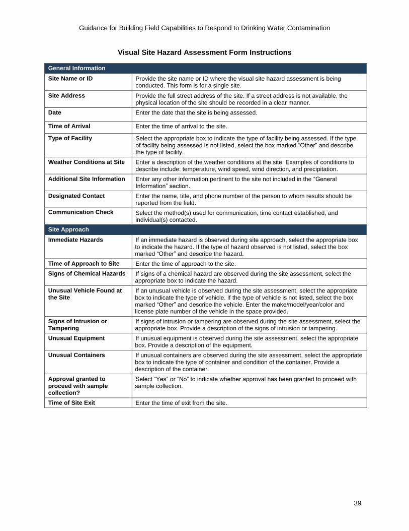
Guidance for Building Field Capabilities to Respond to Drinking Water Contamination
Visual Site Hazard Assessment Form Instructions
General Information
Site Name or ID Provide the site name or ID where the visual site hazard assessment is being conducted. This form is for a single site.
Site Address Provide the full street address of the site. If a street address is not available, the physical location of the site should be recorded in a clear manner.
Date Enter the date that the site is being assessed.
Time of Arrival Enter the time of arrival to the site.
Type of Facility Select the appropriate box to indicate the type of facility being assessed. If the type of facility being assessed is not listed, select the box marked “Other” and describe the type of facility.
Weather Conditions at Site Enter a description of the weather conditions at the site. Examples of conditions to describe include: temperature, wind speed, wind direction, and precipitation.
Additional Site Information Enter any other information pertinent to the site not included in the “General Information” section.
Designated Contact Enter the name, title, and phone number of the person to whom results should be reported from the field.
Communication Check Select the method(s) used for communication, time contact established, and individual(s) contacted.
Site Approach
Immediate Hazards If an immediate hazard is observed during site approach, select the appropriate box to indicate the hazard. If the type of hazard observed is not listed, select the box marked “Other” and describe the hazard.
Time of Approach to Site Enter the time of approach to the site.
Signs of Chemical Hazards If signs of a chemical hazard are observed during the site assessment, select the appropriate box to indicate the hazard.
Unusual Vehicle Found at the Site
If an unusual vehicle is observed during the site assessment, select the appropriate box to indicate the type of vehicle. If the type of vehicle is not listed, select the box marked “Other” and describe the vehicle. Enter the make/model/year/color and license plate number of the vehicle in the space provided.
Signs of Intrusion or Tampering
If signs of intrusion or tampering are observed during the site assessment, select the appropriate box. Provide a description of the signs of intrusion or tampering.
Unusual Equipment If unusual equipment is observed during the site assessment, select the appropriate box. Provide a description of the equipment.
Unusual Containers If unusual containers are observed during the site assessment, select the appropriate box to indicate the type of container and condition of the container. Provide a description of the container.
Approval granted to proceed with sample collection?
Select “Yes” or “No” to indicate whether approval has been granted to proceed with sample collection.
Time of Site Exit Enter the time of exit from the site.
39

40
Guidance for Building Field Capabilities to Respond to Drinking Water Contamination
Appendix A-2: Example Laboratory Capabilities
Below are example laboratory capabilities to illustrate the information needed to prepare sample bottles,
supplies, and shipping information.
Contaminant or Class Method Laboratory and
Shipping Address Emergency
Point-of-Contact Emergency
Phone Number
Total organic carbon (TOC)
SM1
5310 B
Utility Lab
--address-
Primary:
Backup:
(xxx) xxx-xxxx
(xxx) xxx-xxxx
UV254 SM1
5910 B
Semi-volatile organic compounds (SVOC) screen
EPA 3510 C/8270 D
Volatile organic compounds and total trihalomethanes (TTHMs)
EPA 524.2
Anions EPA 300.1
Coliforms/E. coli SM1
9223 (Colilert-18®)
Glyphosate EPA 547
Environmental Laboratory A
--address-
Primary:
Backup:
(xxx) xxx-xxxx
(xxx) xxx-xxxx
Diquat and paraquat EPA 549.2
Carbamate pesticides EPA 531.2
Diesel range organics screen
EPA 3510 C/8015 C
Metals EPA 200.8
Total cyanide EPA 335.4
Microcystins and nodularin
EPA 544
Environmental Laboratory B
--address-
Primary:
Backup:
(xxx) xxx-xxxx
(xxx) xxx-xxxx
Cryptosporidium/Giardia EPA 1623
Haloacetic acids (HAA5) EPA 552.2
Radiochemical – gross alpha and beta
EPA 900.0
State Health Laboratory
--address-
Primary:
Backup:
(xxx) xxx-xxxx
(xxx) xxx-xxxx
Radiochemical – gross gamma
EPA 901.1
Select pathogens and biotoxins
LRN2
Bioterrorism Threat (BT) Agent Screening Protocol
1Standard Methods for the Examination of Water and Wastewater
2Laboratory Response Network
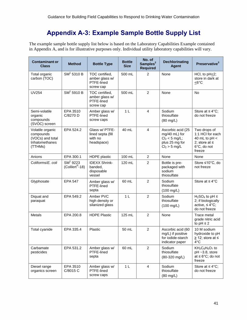
Guidance for Building Field Capabilities to Respond to Drinking Water Contamination
Appendix A-3: Example Sample Bottle Supply List
The example sample bottle supply list below is based on the Laboratory Capabilities Example contained
in Appendix A, and is for illustrative purposes only. Individual utility laboratory capabilities will vary.
Contaminant or Class
Method Bottle Type Bottle Size
No. of Samples
2
Required
Dechlorinating Agent
Preservative3
Total organic carbon (TOC)
SM1
5310 B TOC certified, amber glass w/ PTFE-lined screw cap
500 mL 2 None HCl, to pH<2; store in dark at <6°C
UV254 SM1
5910 B TOC certified, amber glass w/ PTFE-lined screw cap
500 mL 2 None No
Semi-volatile organic compounds (SVOC) screen
EPA 3510 C/8270 D
Amber glass w/ PTFE-lined screw caps
1 L 4 Sodium thiosulfate
(80 mg/L)
Store at ≤ 4°C; do not freeze
Volatile organic compounds (VOCs) and total trihalomethanes (TTHMs)
EPA 524.2 Glass w/ PTFE-lined septa (fill with no headspace)
40 mL 4 Ascorbic acid (25 mg/40 mL) for Cl2 < 5 mg/L; plus 25 mg for Cl2 > 5 mg/L
Two drops of 1:1 HCl for each 40 mL to pH < 2; store at ≤ 6°C, do not freeze
Anions EPA 300.1 HDPE plastic 100 mL 2 None None
Coliforms/E. coli SM1
9223 (Colilert
® -18)
IDEXX Shrink-banded, disposable vessel
120 mL 2 Bottle is prepackaged with sodium thiosulfate
Store ≤10°C, do not freeze
Glyphosate EPA 547 Amber glass w/ PTFE-lined septa
60 mL 2 Sodium thiosulfate
(100 mg/L)
Store at ≤ 4°C
Diquat and paraquat
EPA 549.2 Amber PVC high density or silanized glass
1 L 2 Sodium thiosulfate
(100 mg/L)
H2SO4 to pH ≤ 2; if biologically active, ≤ 4°C; do not freeze
Metals EPA 200.8 HDPE Plastic 125 mL 2 None Trace metal grade nitric acid to pH ≤ 2
Total cyanide EPA 335.4 Plastic 50 mL 2 Ascorbic acid (60 mg/L) if positive for iodide-starch indicator paper
10 M sodium hydroxide to pH ≥ 12; store at ≤ 4°C
Carbamate pesticides
EPA 531.2 Amber glass w/ PTFE-lined septa
60 mL 2 Sodium thiosulfate
(80-320 mg/L)
KH2C6H5O7 to pH ~3.8, store at ≤ 6°C; do not freeze
Diesel range organics screen
EPA 3510 C/8015 C
Amber glass w/ PTFE-lined screw caps
1 L 4 Sodium thiosulfate
(80 mg/L)
Store at ≤ 4°C; do not freeze
41

Guidance for Building Field Capabilities to Respond to Drinking Water Contamination
Contaminant or Class
Method Bottle Type Bottle Size
No. of Samples
2
Required
Dechlorinating Agent
Preservative3
Microcystins and EPA 544 Amber glass w/ 500 mL 2 Ascorbic acid Trizma - 7.75 nodularin PTFE-lined (100 mg/L) g/L; 2
screw caps Chloroacetamid e, 2 g/L; EDTA, 0.35 g/L; store at ≤6°C
Cryptosporidium/ EPA 1623 LDPE 10 L 2 Sterile sodium Store ≤10°C, do Giardia Cubitainer thiosulfate not freeze
(sterile) (0.01% final)
Haloacetic acids EPA 552.2 Amber glass w/ 60 mL 2 None Ammonium (HAA5) PTFE-lined chloride (100
septa mg/L)
Radiochemical – EPA 900.0 Plastic 1 L 2 None Nitric acid to pH gross alpha and (polypropylene, < 2 beta polyethylene) or
borosilicate glass
Radiochemical – gross gamma
EPA 901.1 Plastic (polypropylene, polyethylene) or borosilicate
1 L 2 None Nitric acid to pH < 2
glass
Select pathogens LRN4
LDPE 20 L 2 10 mL of sterile Store ≤10°C, do and biotoxins Bioterrorism
Threat (BT) Cubitainer (sterile)
10% (w/v) sodium
not freeze
Agent thiosulfate Screening Protocol
1Standard Methods for the Examination of Water and Wastewater
2Number of samples required per sampling location, not including field blanks.
3Unless otherwise indicated all samples will be shipped on ice and stored as specified.
4Laboratory Response Network
42

- -
Guidance for Building Field Capabilities to Respond to Drinking Water Contamination
Appendix A-4: Water Quality Parameter Report Form
General Information
Site Name or ID: Date:
Site Address: Sample Collection Time:
Team Members: Report Form ID:
Designated Contact (Name, Title, and Phone Number):
Meter/Kit IDs
Field Point of Use QC
Parameter Blank or
Background Result
QC Lot Number QC True Value QC Result Acceptance
Range
****STOP and REPORT****
If a field point-of-use QC result is outside of acceptance range, report the result to the Designated Contact before proceeding.
Sample Results
Parameter Units Sample Result Duplicate Result Expected Range
*****STOP and REPORT****
Verbally report results to Designated Contact.
Deviations from SOP(s) and Other Notes
Submitted By
Report Submitted By (PRINT):
Report Submitted By (Signature):
Date:
43

- -
Guidance for Building Field Capabilities to Respond to Drinking Water Contamination
Water Quality Parameter Report Form Instructions
General Information
Site Name or ID Provide the site name or ID where water quality parameters are being measured. This form is for a single sample location.
Site Address Provide the full street address of the site. If a street address is not available the physical location of the site should be recorded in a clear manner.
Team Members Record the names of team members performing water quality parameter testing.
Designated Contact Enter the name, title, and phone number of the person to whom results should be reported from the field.
Date Enter the date that the water quality parameters are measured.
Sample Collection Time Enter the collection time for the sample.
Report Form ID Enter a unique ID number for the form. This number will be used to link water quality parameter results to samples on the chain of custody form.
Meter/Kit IDs
Enter the ID for the meter or kit used to measure the water quality parameters.
Field Point of Use QC
Parameter List the parameters that are being measured. Field point-of-use QC samples are analyzed in the field before analyzing collected samples.
Blank or Background Result
Enter the result(s) for blank or background sample(s), if taken.
QC Lot Number Enter the lot number(s) for the point-of-use QC sample(s). Point-of-use QC samples may not be analyzed at every sample location.
QC True Value Enter the true value(s) for the point-of-use QC sample(s).
QC Result Enter the result(s) for the point-of-use QC sample(s).
Acceptance Range Enter the acceptance range for the point-of-use QC sample(s).
Sample Results
Units Enter the units for the sample result(s).
Sample Result Enter the result(s) for the sample(s).
Duplicate Result Enter the result(s) for the duplicate measurement(s), if taken.
Expected Range Enter the expected range for the water quality parameter(s) based on current expected values for location. The expected range should be known before water quality parameter testing.
Deviations from SOP(s) and Other Notes
Document any deviations or changes to SOP(s) or other notes related to water quality parameter testing.
Submitted By
Report Submitted By (PRINT)
The printed name of the individual recording results and submitting the report to the utility manager or Incident Commander.
Report Submitted By (Signature)
The signature of the individual recording results and submitting the report to the utility manager or Incident Commander.
Date The date the results are submitted to the utility manager or Incident Commander.
44

Utility Name:
Street Address:
City, State, Zip Code:
Point-of-Contact:
Point-of-Contact Phone #:
Recipient laboratory if different from above:
Laboratory Name:
Shipping Address:
City, State, Zip Code:
Point-of-Contact:
Point-of-Contact Phone #:
Analysis Request
Enter Preservation Code1
Utility Project ID #:
COC ID #:
Cooler ID #:
Field Samplers:
COC Completed by:
Page ____ of _____
Total # Bottles in Cooler:
Requested Turnaround Time:
****Laboratory Use Only****
Laboratory Project ID #:
Samples Received
Date and Time:
Samples Checked Against COC by:
Samples Received Temp.:
Cooler Custody Seal Intact?
Yes No None
Sample Custody Seals Intact?
Yes No None
G,C
, or
S2
If S
ub-s
ampl
ed,
Larg
e B
ottle
ID
Collected
Location Check Below for Requested Analysis
ID3 Date Time Wat
er Q
ualit
y
Par
amet
erR
epor
t ID
Rap
id F
ield
Tes
ting
Rep
ort I
D
Sample ID Remarks
1Preservation Codes: 1=Ice; 2=HCI; 3=H2SO4; 4=HNO3; 5=NaOH; 6=Ascorbic Acid; 7=Sodium Sulfite; Special Instructions:
8=Sodium Thiosulfate; 9=Potassium Dihydrogen Citrate. Other Codes: 2G=Grab, C=Composite, S=Sub-sampled
3If all samples are from the same location, enter address here:
Signature Affiliation Date and Time Signature Affiliation Date and Time
Relinquished by: Received by:
Relinquished by: Received by:
Relinquished by: Received by:
Relinquished by: Received by:
Guidance for Building Field Capabilities to Respond to Drinking Water Contamination
Appendix A-5: Emergency Response Chain of Custody Form
45

Guidance for Building Field Capabilities to Respond to Drinking Water Contamination
Emergency Response Chain of Custody Form Instructions
Address Field
Enter the utility name, address, and point-of-contact information. Enter the laboratory address and point-of-contact information, if different from the utility.
Analysis Request
In each column enter a specific analysis that will be requested.
Enter Preservation Code
Enter the preservation code if preservative is added to the sample bottle in the field, or is provided in the bottle from the laboratory. For convenience, common preservatives are footnoted below.
COC Information
Utility Project ID # Enter the utility project ID number if assigned.
COC ID # Enter the ID number for the COC.
Page _____ of ______ If multiple COCs will be grouped together, enter the number of the current COC out of the total number of COCs in the group.
Cooler ID # Enter the ID number for the cooler associated with the COC.
Total # Bottles in Cooler Enter the total number of bottles included in the shipping cooler.
Field Samplers Enter the names, or IDs, of the field samplers who collected samples.
Requested Turn Around Time If a specific turnaround time is requested, it should be entered here. Leave this field blank if it is not applicable.
COC completed by Enter the name, or ID, of the individual who completed the COC.
****Laboratory Use Only****
Laboratory Project ID # Enter the laboratory project ID number if assigned.
Samples Received Temp. Record the temperature of the samples when received at the laboratory.
Samples Received Date and Time Enter the date and time of receipt of samples at the laboratory.
Cooler Custody Seal Intact? Record if the custody seal was intact when received at the laboratory.
Sample Custody Seals Intact? Record if the custody seals were intact when the samples were received at the laboratory.
Samples Checked Against COC by Enter the name of the individual who checks the samples against the COC.
Sample Information
Sample ID Enter the sample ID for each bottle. Each sample bottle should be entered on a different row and have a unique ID.
G, C, or S Enter the appropriate code for the sample: G for a grab sample, C for a composite sample, or S for a sub-sample from a large volume container.
If Sub-Sampled, Large Bottle ID Enter the ID of the large bottle from which sample was sub-sampled.
Location ID Provide the location ID for each sample. If all samples are from same location, enter the address below.
Collected Date/Time Enter the date and time the sample was collected. Use 24 hour military time.
Check Below For Analysis Requested
Enter a check mark at the intersection of the “Sample ID” row and “Analysis Request” column for the analysis that is requested.
Water Quality Parameter Report ID Enter the Water Quality Parameter Report ID for the sample. If none performed, enter “none”.
Rapid Field Testing Report ID Enter the Rapid Field Testing Report ID for the sample. If none performed, enter “none”.
Remarks Enter any remarks related to the sample.
Special Instructions
Enter any special instructions that relate to all of the samples listed on the COC in this area.
Sample Transfer Documentation
Individuals who relinquish or receive the samples should sign the COC form, enter their affiliation, and enter the date and time of each transfer of samples. Use 24 hour military time.
46

Guidance for Building Field Capabilities to Respond to Drinking Water Contamination
Appendix BForms and Templates for Advanced Field Response Activities
47

Appendix B-1: HazMat Interview Form
The following interview form is provided to facilitate information exchange between local HazMat and
the utility.
Attendees Organization Phone Email
Guidance for Building Field Capabilities to Respond to Drinking Water Contamination
1. What geographic area do HazMat responders in your organization serve?
2. What type of incidents do HazMat responders in your organization typically respond to?
3. Do HazMat responders in your organization have experience collecting drinking water samples using
prescribed SDWA approved methods?
□ Yes □ No
If yes, what types of sampling locations?
□ Taps □ Confined spaces (at a water utility)
□ Fire hydrants □ Online water quality monitors (autosamplers)
□ Water storage tanks □ Reservoirs
4. If the HazMat responders in your organization do not have experience with water sampling, are they
willing to be trained?
□ Yes □ No
48

Guidance for Building Field Capabilities to Respond to Drinking Water Contamination
5. Complete the tables below with information provided by HazMat for Site Safety Screening and Rapid
Field Testing. HazMat responders may not have information regarding sensitivity or sensitivity for
contaminants in water readily available. It may be beneficial to schedule a follow-up conversation
regarding rapid field testing specifically for water samples.
Parameter
Matrix
(air, liquids, powders, solids,
surfaces)
Instrumentation
or Test Kit Sensitivity
Sensitivity for Dilute Contaminants in Water?
Example: Toxic industrial chemicals, explosives, narcotics
Solid or liquid chemicals and chemical mixtures
FirstDefender™ RMX Handheld Chemical Identification Analyzer
Trace for liquid and solid chemicals
No
Radiation
Volatile organic compounds/combustible gases
Semi-volatile organic compounds
Toxic industrial chemicals
Chemical warfare agents
Toxins
Pathogens
6. Would the HazMat responders in your organization be willing to participate in tabletop exercises or
field exercises for drinking water contamination emergencies?
□ Yes □ No
7. Can you package and ship hazardous materials?
□ Yes □ No
8. Are there additional HazMat capabilities that you are planning to develop in the near future? If yes,
please describe.
49

Guidance for Building Field Capabilities to Respond to Drinking Water Contamination
Appendix B-2: Site Safety Screening Report Form
General Information
Site Name or ID: Date:
Site Address: Time of Arrival:
Team Members: Report Form ID:
Designated Contact (Name, Title, and Phone Number):
Meter/Kit IDs
Instrument Checks
Parameter Blank or
Background Result
Instrument Checks
Performed
Instrument Check
Reference Value
Instrument Check Result
Acceptance Range
****STOP and REPORT****
If an instrument check result is outside of acceptance range, report the result to the Designated Contact before proceeding.
Sample Results
Parameter Units Expected Range Action Level Action Level
Exceeded? (Y/N) Recorded
Result
****STOP and REPORT****
Verbally report results to the Designated Contact.
Deviations from SOP(s) and Other Notes
Submitted By
Report Submitted By (PRINT):
Report Submitted By (Signature):
Date:
50

Guidance for Building Field Capabilities to Respond to Drinking Water Contamination
Site Safety Screening Report Form Instructions
General Information
Site Name or ID Provide the site name or ID where site safety screening is being conducted. This form is for a single site.
Site Address Provide the full street address of the site. If a street address is not available the physical location of the site should be recorded in a clear manner.
Team Members Record the names of team members performing site safety screening.
Designated Contact Enter the name, title, and phone number of the person to whom results should be reported from the field.
Date Enter the date that the site safety screening is performed.
Time of Arrival Enter the time the team arrives at the site and begins site safety screening.
Report Form ID Enter a unique ID number for this form.
Meter/Kit IDs
Enter the ID for the meter or kit used to measure the site safety screening parameters.
Instrument Checks
Parameter List the parameters that are being measured. Instrument checks are typically conducted in the field before entering the site.
Blank or Background Result
Enter the result(s) for blank or background sample(s), if taken.
Instrument Checks Performed
Enter the instrument checks that are performed to ensure instrumentation is operational and ready for use.
Instrument Check Reference Value
Enter the reference value(s) for the instrument check(s), if applicable.
Instrument Check Result
Enter the result(s) for the instrument check(s).
Acceptance Range Enter the acceptance range for instrument check(s).
Sample Results
Parameter List the parameters that are being measured.
Units Enter the units for the parameter result(s).
Expected Range Enter the expected range for the site safety screening parameter(s) based on baseline/historical data for the site.
Action Level Enter the action level set by the utility for each site safety screening parameter.
Action Level Exceeded? (Y/N)
Enter Y if action level is exceeded and N if the action level is not exceeded.
Recorded Result The highest observed result should be recorded for each parameter. If results are within the normal range, they may be recorded as “Normal.” If the action level is exceeded, this result should be recorded.
Deviations from SOP(s) and Other Notes
Document any deviations or changes to SOP(s) or other notes related to site safety screening.
Submitted By
Report Submitted By (PRINT)
The printed name of the individual recording results and submitting the report to the utility manager or Incident Commander.
Report Submitted By (Signature)
The signature of the individual recording results and submitting the report to the utility manager or Incident Commander.
Date The date the results are submitted to the utility manager or Incident Commander.
51

Guidance for Building Field Capabilities to Respond to Drinking Water Contamination
Appendix B-3: Rapid Field Testing Report Form
General Information
Site Name or ID: Date:
Site Address: Sample Collection Time:
Team Members: Report Form ID:
Designated Contact (Name, Title, and Phone Number):
Meter/Kit IDs
Field QC Samples
Parameter Blank or
Background Result
QC Lot Number QC True Value QC Result Acceptance
Range
****STOP and REPORT****
If a field QC result is outside of acceptance range, report the result to the Designated Contact before proceeding.
Sample Results
Parameter Units Sample Result Duplicate Result Expected Range
****STOP and REPORT****
Verbally report results the Designated Contact.
Deviations from SOP(s) and Other Notes
Submitted By
Report Submitted By (PRINT):
Report Submitted By (Signature):
Date:
52

Guidance for Building Field Capabilities to Respond to Drinking Water Contamination
Rapid Field Testing Report Form Instructions
General Information
Site Name or ID Provide the site name or ID where rapid field testing is being conducted. This form is for a single sample location.
Site Address Provide the full street address of the site. If a street address is not available the physical location of the site should be recorded in a clear manner.
Team Members Record the names of team members performing rapid field testing.
Designated Contact Enter the name, title, and phone number of the person to whom results should be reported from the field.
Date Enter the date that the rapid field testing is performed.
Sample Collection Time Enter the collection time for the sample.
Report Form ID Enter a unique ID number for this form. This number will be used to link rapid field testing results to samples on the chain of custody form.
Meter/Kit IDs
Enter the ID for the meter or kit used to measure the rapid field testing parameters.
Field QC Samples
Parameter List the parameters that are being measured. Field QC samples are analyzed in the field before analyzing collected samples.
Blank or Background Result
Enter the result(s) for blank or background sample(s), if taken.
QC Lot Number Enter the lot number(s) for the field QC sample(s). Field QC samples may not be analyzed at every sample location.
QC True Value Enter the true value(s) for the field QC sample(s).
QC Result Enter the result(s) for the field QC sample(s).
Acceptance Range Enter the acceptance range for the field QC sample(s).
Sample Results
Parameter List the parameters that are being measured.
Units Enter the units for the sample result(s).
Sample Result Enter the result(s) for the sample(s).
Duplicate Result Enter the result(s) for the duplicate measurement(s), if taken.
Expected Range Enter the expected range for the rapid field testing parameters based on baseline/historical data.
Deviations from SOP(s) and Other Notes
Document any deviations or changes to SOP(s) or other notes related to rapid field testing.
Submitted By
Report Submitted By (PRINT)
The printed name of the individual recording results and submitting the report to the utility manager or Incident Commander.
Report Submitted By (Signature)
The signature of the individual recording results and submitting the report to the utility manager or Incident Commander.
Date The date the results are submitted to the utility manager or Incident Commander.
53

Guidance for Building Field Capabilities to Respond to Drinking Water Contamination
Appendix C: Staffing Plan Template
Responsibilities Primary Contact Phone Backup Contact Phone Availability
□ Day □ Night
□ Day □ Night
□ Day □ Night
□ Day □ Night
□ Day □ Night
□ Day □ Night
□ Day □ Night
□ Day □ Night
□ Day □ Night
□ Day □ Night
□ Day □ Night
□ Day □ Night
□ Day □ Night
□ Day □ Night
□ Day □ Night
□ Day □ Night
□ Day □ Night
54

Guidance for Building Field Capabilities to Respond to Drinking Water Contamination
Appendix D: Site Characterization and Sampling Plan
Investigation Site
Site Name: Additional Site Information:
Site Address:
Type of Facility: Source water
Ground storage tank
Tap
Treatment plant
Elevated storage tank
Hydrant
Pump station
Finished water reservoir
Service connection
Water quality monitoring station
Other: ___________________________________________________
Initial Information Known:
Customer complaints
Water quality anomaly
Reported illnesses
Security alert
Other: ___________________________________________________
Field Activities
Visual site hazard assessment
Site safety screening
Water quality parameter testing
Rapid field testing
Sample collection for laboratory analysis
Site Safety Screening
Parameter Parameter
Water Quality Parameters
Parameter Parameter
Rapid Field Testing
Parameter Parameter
Sampling Plan
Distribution main
Service line
Premise
Other: ________________________________
Composite sample
Grab sample
Large volume sample collection without sub-sampling
Large volume sample collection with sub-sampling
Contaminant or class listed below
Contaminant or class described in attached plan
Contaminant or Contaminant Class Contaminant or Contaminant Class
55

Guidance for Building Field Capabilities to Respond to Drinking Water Contamination
Sample Delivery: Return samples to utility Ship samples to pre-arranged laboratories
Recipient listed below
Name:
Address:
Phone No.:
Field Response Personnel
Utility Site Characterization Team:____________________________________________
Water quality technician:_______________________________________________
Field samplers:______________________________________________________
Security officer:______________________________________________________
Distribution system operator:____________________________________________
Other: _____________________________________________________________
Participating Agencies
Local law enforcement
HazMat
Fire department
FBI
Civil Support Team
Primacy Agency
EPA Response Team
Other: ____________________
Participating Agency will:
Deploy with utility personnel
Meet at location site at (specify time)
Communications
Mode of Communication:
Phone 2-way radio Digital
Other: _____________________________________________________
Reporting Events: Upon arrival at site
During approach
Site entry
Site exit
After field testing
Other: __________________________
Report To: Phone No.:
Health and Safety
Health and Safety Plan: Reviewed
Modified If modified, describe:______________________________
Personal Protective Equipment Personal Protective Equipment
Approvals
Health and Safety Officer
Name (PRINT):
Signature: Date:
Utility Manager or Incident Commander
Name (PRINT):
Signature: Date:
56

Appendix E: Emergency Response Sampling and Analysis Kit Inventory Sheet Templates
Sample Bottle Kit Inventory Sheet [Specify Storage Location]
Contaminant or Class
Bottle Type and Volume
Number of Bottles Dechlorinating
Agent in Bottle? Preservative In
Bottle?
Other included items: (i.e., Pre-filled COC form, Sampling Instructions, Delivery Instructions)
Prepared By: Date:
Checked By: Date:
Kit Expiration Date:
Guidance for Building Field Capabilities to Respond to Drinking Water Contamination
Supply Kit Inventory Sheet [Specify Storage Location]
Item Quantity Item Quantity
Prepared By: Date:
Checked By: Date:
57

Guidance for Building Field Capabilities to Respond to Drinking Water Contamination
1
Supplemental Information: Rapid Field Testing Instrumentation and Test Kits
This document provides additional information regarding rapid field testing instrumentation and test kits
including a description of the technology, the relative cost to purchase and maintain the instruments or
test kits, the contaminants or class of contaminants that can be detected, ease of use, interferences, and
training. This information was gathered during 2016 from EPA and individual vendor resources.
The EPA Environmental Technology Verification (ETV) program and Homeland Security Technology
Testing & Evaluation Program (TTEP) provide reports and statements based on high-quality, peer-
reviewed data on technology use and performance. These reports and others are listed to provide
information to help the reader make decisions regarding the type of rapid field testing instruments to
purchase. Additional information is available online through the ETV program’s website
(http://archive.epa.gov/nrmrl/archive-etv/web/html/) and TTEP reports from National Homeland Security
Research Center (NHSRC) (https://www.epa.gov/homeland-security-research) through a keyword search
of the available research products. However, it should be noted that the ETV program and TTEP
information has been archived and new technologies may exist that have not been verified through these
programs.
The instruments listed in this document are representative of what is available for screening of specific
contaminants or classes of contaminants in drinking water samples. Some of the instruments listed in the
following sections are more likely to be used by trained HazMat responders than water utility personnel.
They are listed here for informational purposes only.
Cyanide Field methods can measure the free cyanide ion, which is the most toxic form. Rapid field tests do not
measure all cyanide complexes. Table 1 provides a summary of available instrumentation for cyanide
testing. Mention of specific vendors is not an endorsement for use.

Guidance for Building Field Capabilities to Respond to Drinking Water Contamination
2
Table 1. Cyanide Testing Instrumentation and Test Kits
Vendor Technology Model Application References Initial Cost
1
Maintenance Cost Per
Year1
Thermo Fisher
http://www.thermoscientific.com/
Portable Cyanide Analyzer
AQUAfast® IV AQ4000 colorimeter with Cyanide Reagents
Portable colorimeter
Detecting cyanide in water
EPA, 2003, Thermo Orion AQUAfast IV AQ4000 with AQ4006 Cyanide Reagents, EPA/600/r-11/196, Washington, D.C.
EPA, 2005. Technologies and Techniques for Early Warning Systems to Monitor and Evaluate Drinking Water Quality: A State-of-the-Art Review, EPA/600/R-05/156, Washington, D.C.
$-$$ $
CHEMetrics, Inc.
https://www.chemetrics.com/
Portable Cyanide Analyzer
V-2000 with K-3803 Cyanide Module
Portable multi-analyte photometer
EPA, 2003. CHEMetrics, Inc. VVR V-1000 Multi-Analyte Photometer with the V-3803 Cyanide Module, EPA/600/R-11/190, Washington, D.C.
EPA, 2005. Technologies and Techniques for Early Warning Systems to Monitor and Evaluate Drinking Water Quality: A State-of-the-Art Review, EPA/600/R-05/156, Washington, D.C.
$$ $
LaMotte Company
http://www.lamotte.com/
Portable Cyanide Analyzer
SMART 3 Colorimeter with 3660-SC Reagent System
Portable colorimeter
EPA, 2003. 1919 SMART 2 Colorimeter With the 3660-SC Reagent System. EPA/600/R-11/194, Washington, D.C.
EPA, 2005. Technologies and Techniques for Early Warning Systems to Monitor and Evaluate Drinking Water Quality: A State-of-the-Art Review, EPA/600/R-05/156, Washington, D.C.
$$ $
Lovibond
Tintometer Inc.
http://www.lovibond.us
Portable Cyanide Analyzer
Lovibond MD 610
Portable photometer
EPA, 2003. Orbeco-Hellige Mini-analyst Model 942-032, EPA/600/R-11/195, Washington, D.C.
EPA, 2005. Technologies and Techniques for Early Warning Systems to Monitor and Evaluate Drinking Water Quality: A State-of-the-Art Review, EPA/600/R-05/156, Washington, D.C.
$$ $

Guidance for Building Field Capabilities to Respond to Drinking Water Contamination
3
Vendor Technology Model Application References Initial Cost
1
Maintenance Cost Per
Year1
Thermo Fisher
http://www.thermoscientific.com/
Ion Selective Electrode
Model 9406 Cyanide Electrode with Model A324 ISE Meter
Non-portable probe
EPA, 2003. Thermo Orion Model 9606 Cyanide Electrode with Model 290 A+ Ion Selective Electrode Meter, EPA/600/R-11/197, Washington, D.C.
EPA, 2005. Technologies and Techniques for Early Warning Systems to Monitor and Evaluate Drinking Water Quality: A State-of-the-Art Review, EPA/600/R-05/156, Washington, D.C.
$$ $
WTW Measurement Systems
http://www.wtw.com
Ion Selective Electrode
Cyanide Electrode CN 500 with Reference Electrode R503D, and Ion Pocket Meter 340i
Non-portable probe
EPA, 2003. WTW Measurement Systems Cyanide Electrode CN501 With Reference Electrode R503D, and Ion Pocket Meter 340i, EPA/600/R-11/198, Washington, D.C.
EPA, 2005. Technologies and Techniques for Early Warning Systems to Monitor and Evaluate Drinking Water Quality: A State-of-the-Art Review, EPA/600/R-05/156, Washington, D.C.
$$ $
Industrial Test Systems, Inc.
http://www.sensafe.com
Colorimetric Test Strips
eXact Reagent Strip™
Color development test strip
EPA, 2005. Industrical test Systems, Inc. Cyandie Reagent Strip Test Kit, EPA/600/R-11/193, Washington, D.C.
$ Not applicable
1$ represents $0-$999, $$ represents $1000-$9999, $$$ represents >$10,000

Guidance for Building Field Capabilities to Respond to Drinking Water Contamination
4
Details about the technologies described in Table 1 are provided below.
Portable Cyanide Analyzer (Field spectrophotometer)
o Used to measure grab samples in the field.
o Field spectrophotometer may be used for multiple field tests.
o Two reagents are added to adjust pH and quench chlorine.
o Grab sample is placed in a test tube or drawn into a reagent vacuum-ampoule.
o Color development of reagents sensitive to cyanide.
o Ampoules are self-contained and store the sample and reagents allowing for disposal later at a
lab facility.
o Easy to run and requires minimal training.
Ion Selective Electrode (ISE)
o Used in combination with a field instrument that can measure millivolts to detect cyanide.
o A three point calibration curve that takes 15 to 30 minutes is necessary prior to testing on
each day of use.
o Using the ISE probe and developing a calibration curve is more challenging than the
spectrophotometer method and requires a moderate level of training.
o Easy to use but the ISE probes can be sensitive to environmental conditions and may be
better suited to use in the laboratory.
Field Test Strips
o A color development test based on conversion of cyanide in water to cyanogen chloride.
o Provided semi-quantitative (absence/presence) measurement of the free cyanide ion.
o Results in one minute.
o Higher detection limits than other methods.
o In the presence of isonicotinic and barbituric acids, the cyanogen chloride produces a color
change.
o Color change is detected visually or with a colorimeter.
o Not very reliable below room temperature. Therefore, this test may not be suitable for many
utilities unless the samples are pre-heated prior to using the test strips.
o Easy to use.
Arsenic Field methods are available for the detection of arsenic, including portable arsenic analyzers and
colormetric test strips, which are relatively inexpensive and can rapidly screen a large number of samples.
Table 2 provides a summary of available instrumentation for arsenic testing. Mention of specific vendors
is not an endorsement for use.

Guidance for Building Field Capabilities to Respond to Drinking Water Contamination
5
Table 2. Arsenic Testing Instrumentation and Test Kits
Vendor Technology Model Application References Initial Cost
1
Maintenance Cost Per
Year1
EMD Millipore
http://www.emdmillipore.com
Portable Arsenic Analyzer
Spectroquant® Move 100 colorimeter with Arsenic Reagents
Portable colorimeter
Detecting arsenic in water
Not applicable $-$$ $
Industrial Test Systems, Inc.
http://www.sensafe.com/
Colorimetric Test Strip
Quick II, Quick Low-Range, Quick Low-Range II, and Quick Ultra-Low II test kits
Color development test kit
https://archive.epa.gov/nrmrl/archive-etv/web/html/ Accessed on 30 June 2016
2
$ $
1$ represents $0-$999, $$ represents $1000-$9999, $$$ represents >$10,000
2Multiple colorimetric test strip technologies with different ranges of sensitivity are available for the detection of arsenic and each is
evaluated in a separate ETV report.
Details about the technologies described in Table 2 are provided below.
Portable Arsenic Analyzer
o Used to measure grab samples in the field.
o Grab sample is placed in a test tube.
o Color development of reagents sensitive to arsenic.
o Ampoules are self-contained and store the sample and reagents allowing for disposal later at a
lab facility.
o Easy to run and requires minimal training.
Field Test Strips
o A color development test with results in ten minutes.
o Provided semi-quantitative (absence/presence) measurement of arsenic.
o The arsenic (inorganic) in water is converted to arsine gas.
o The arsine gas produces a color change when exposed to the test strip (white to yellow or
brown with increasing arsine levels).
o Color change is detected visually or with a colorimeter.
o Field test strips are not very reliable below room temperature. Therefore, field test strips may
not be suitable for many utilities unless the samples are pre-heated prior to using the test
strips.
o Easy to use and requires minimal training.
Organics There are two common types of methods for measuring organics in water samples: portable gas
chromatograph/mass spectrometer (GC/MS) and headspace multi-gas monitors. Table 3 provides a
summary of available instrumentation for organics monitoring. Mention of specific vendors is not an
endorsement for use.

Guidance for Building Field Capabilities to Respond to Drinking Water Contamination
6
Table 3. Organics Testing Instrumentation
Vendor Technology Model Application References Initial Cost
1
Maintenance Cost
1
Inficon, Inc.
http://www.inficon.com/
Portable GC/MS
HAPSITE
Portable GC/MS
EPA, 1998. Field-Portable Gas Chromatograph/Mass Spectrometer, Inficon, Inc., HAPSTIE,
EPA/600/r-98-142, Washington, D.C.
$$$ $$
Bruker Corporation
http://www.bruker.com
Portable GC/MS
E2M Portable GC/MS
EPA, 1997. Field Portable Gas Chromatograph/Mass Spectrometer, Bruker-Franzen Analytical Systems, Inc. EM640, EPA/600/R-97/149, Washington, D.C.
$$$ $$
RAE Systems
http://www.raesystems.com
Headspace Multi-Gas Monitor
MultiRAE PID
Portable PID EPA, 2012. Technology Evaluation Report, Testing and Evaluation of Handheld Toxic Industrial Chemical Detectors, EPA/600/R-
12/560. Washington, D.C.
$$ $
RAE Systems
http://www.raesystems.com
Headspace Multi-Gas Monitor
ppbRAE PID
Portable PID EPA, 2012. Technology Evaluation Report, Testing and Evaluation of Handheld Toxic Industrial Chemical Detectors, EPA/600/R-12/560. Washington, D.C.
2
$$ $
MSA
http://us.msasafety.com
Headspace Multi-Gas Monitor
Sirius®
Multi gas Detector
Portable PID Not applicable $$ $
1$ represents $0-$999, $$ represents $1000-$9999, $$$ represents >$10,000
2The ETV report listed for the ppbRAE PID is for the MultiRAE PID instrument.
Details about the technologies described in Table 3 are provided below.
Portable GC/MS
o Used to identify and measure volatile organic compounds, toxic industrial chemicals, toxic
industrial materials, chemical warfare agents, and select semi-volatile organic compounds.
o Includes a purge and trap system for water samples.
o Pre-concentration accessories can provide high sensitivity to many contaminants.
o The instrument requires approximately 30 minutes to set up on site.
o Approximately two samples can be processed per hour.
o The costs of field portable GC/MS systems may be similar to the costs for a laboratory grade
GC/MS system; however, the laboratory GC/MS may have greater capabilities.
o Designed for ease of use.
o Should only be used by an experienced analyst.
Headspace Multi-Gas Monitor
o Able to detect low vapor pressure volatile organic compounds and some semi-volatile organic
compounds with ionization potentials below ~11 eV.

Guidance for Building Field Capabilities to Respond to Drinking Water Contamination
7
o Uses a headspace screening technique.
o Provides semi-quantitative results.
o Limited to the detection of organic compounds that have double or triple carbon bonds.
o Typical distribution system background levels should be below the limit of detection for the
photoionization detector (PID) since it is not sensitive to most disinfection by-products.
o A presence/absence result is sufficient to indicate contamination.
o Easy to use and require very little training.
Acute Toxicity Many contaminants can produce acute (rapid) toxicity. The toxic effect can be from almost any class of
contaminant such as toxins, organic compounds such as pesticides, and inorganic compounds such as
mercury. Most acute toxicity tests are very sensitive to specific contaminants; however, the tests do not
identify a specific contaminant or even the class of contaminant.
There are three common types of acute toxicity screening tests: chemiluminescence, bioluminescence,
and biological assays. Biological assays are generally not suitable for use in the field and are performed in
the laboratory where the environmental conditions can be controlled. Table 4 provides a summary of
available field instrumentation for acute toxicity monitoring. Mention of specific vendors is not an
endorsement for use.
Table 4. Acute Toxicity Testing Instrumentation
Vendor Technology Model Application References Initial Cost
1
Maintenance Cost
1
HACH
http://www.hach.com
Chemiluminescence Eclox Acute toxicity screening
EPA, 2003. Severn Trent Services Eclox Rapid Toxicity Testing System Technology Verification Report and Statement, EPA/600/R-11/214, Washington, D.C.
EPA, 2005. Technologies and Techniques for Early Warning Systems to Monitor and Evaluate Drinking Water Quality: A State-of-the-Art Review, EPA/600/R-05/156, Washington, D.C.
$$ $
Modern Water
http://www.modernwater.com/
Bioluminescence Deltatox® II
Acute toxicity screening
EPA, 2003. Strategic Diagnostics, Inc. Deltatox Rapid Toxicity Testing System Technology Verification Report and Statement, EPA/600/R-11/215, Washington, D.C.
EPA, 2005. Technologies and Techniques for Early Warning Systems to Monitor and Evaluate Drinking Water Quality: A State-of-the-Art Review, EPA/600/R-05/156, Washington, D.C.
$$-$$$
$
1$ represents $0-$999, $$ represents $1000-$9999, $$$ represents >$10,000

Guidance for Building Field Capabilities to Respond to Drinking Water Contamination
8
Based on the ETV reports and the experiences of water utilities, results of acute toxicity tests can be
highly variable. These tests were found to be more consistent when performed in a controlled
environment or laboratory by an experienced analyst.
Chemiluminescence
o Uses a chemical reaction such as luminal, an oxidant, and a catalyst enzyme (horseradish
peroxidase) in contact with the water sample to determine if there is a change in the
luminescence reading which can indicate a toxic condition.
o Unlike the bioluminescence test, dechlorinated water disinfected by chloramination did not
show a negative interference.
o 15 samples can be processed per hour.
o Should only be used by an experienced analyst.
Bioluminescence
o Uses luminescent bacteria, a micro-bioassay, in contact with the water sample to determine if
there is a change in the luminescence reading which can indicate a toxic condition.
o Nearly complete inhibition (false negative responses) in dechlorinated water disinfected by
chloramination.
o Contaminants would not be detected because the background light is already inhibited by the
drinking water sample matrix.
o 20 samples can be processed per hour.
o Once activated the test reagents should be used within 2 hours.
o Should only be used by an experienced analyst.
Chemical Warfare Agents Colorimetric detection systems are the most efficient method for monitoring presence of chemical warfare
agents such as G-nerve agents, VX (nerve agent), sulfur mustard and lewisite (blood agents), and
hydrogen cyanide (blister agent). Table 5 provides a summary of available instrumentation for chemical
warfare agents testing. Mention of specific vendors is not an endorsement for use.
Table 5. Chemical Warfare Agents Testing Instrumentation
Vendor Technology Model Application References Initial Cost
1
Maintenance Cost
1
HACH
http://www.hach.com
Field test strips
Eclox Enzymatic test kit for detecting chemical warfare agents, carbamate pesticides, and organophosphate pesticides in drinking water
EPA, 2006. EcloxTM-Pesticde Strips verification report and statement, EPA/600/R-11/128, Washington, D.C.
$-$$ $-$$
Luxfer Magtech, Inc.
http://www.luxfermagtech.com
Chemical Agent Water Testing Kit
M272 Testing of water for the presence of toxic industrial chemicals and chemical warfare agents
DHS, 2007. Guide for the Selection of Chemical Detection Equipment for Emergency First Responders, 3
rd
Edition, Guide 100-06. Washington, D.C.
$ $
1$ represents $0-$999, $$ represents $1000-$9999, $$$ represents >$10,000

Guidance for Building Field Capabilities to Respond to Drinking Water Contamination
9
Details about the technologies described in Table 5 are provided below.
Colorimetric Detection
o Capable of detecting chemical warfare agents within six to seven minutes.
o The test kits/test strips have shown a false positive result for chemical warfare agents when
organophosphate pesticides are present.
o Two separate detection technologies exist: one for toxic industrial chemicals and one for
chemical warfare agents.
o Toxic industrial chemical technology requires a 60 mL sample and uses reagent tablets, color
tubes, and heating provided by lighted matches to obtain a qualitative indication of the
presence of chemicals in the sample.
o Reagents have a relatively short shelf-life which can contribute to higher costs to maintain
this test kit.
o Should only be used by experienced analysts.

Guidance for Building Field Capabilities to Respond to Drinking Water Contamination
1
Supplemental Information: Site Safety Screening Instrumentation and Test Kits
This document provides additional information regarding site safety screening instrumentation and test
kits including a description of the technology, the relative cost to purchase and maintain the instruments
or test kits, parameters and contaminants that can be monitored, interferences, ease of use, and training.
This information was gathered during 2016 from EPA’s website and individual vendor resources.
The EPA Environmental Technology Verification (ETV) program and Homeland Security Technology
Testing & Evaluation Program (TTEP) provide reports and statements based on high-quality, peer-
reviewed data on technology use and performance. These reports and others are listed to provide
information to help the reader make decisions regarding the type of site safety screening instruments to
purchase. Additional information is available online through the ETV program’s website
(http://archive.epa.gov/nrmrl/archive-etv/web/html/) and TTEP reports from the National Homeland
Security Research Center (NHSRC) (https://www.epa.gov/homeland-security-research) through a
keyword search of the available research products. However, it should be noted that the ETV program and
TTEP information has been archived and new technologies may exist that have not been verified through
these programs.
The instruments listed in this document are representative of what is available for screening of
radioactivity, gases, and chemical agents. Some of the instruments listed in the following sections are
more likely to be used by trained HazMat responders than water utility personnel. They are listed here for
informational purposes only. Additionally, there are multiple site safety screening instrumentation
vendors from which to choose. Vendor support, training, warranties, and ongoing maintenance costs
should be considered before purchasing site safety screening instruments.
Radioactivity Radioactivity can be detected using various types of instruments.
Sensor Technologies
Radiation is monitored with a probe that detects radioactivity and a meter that alerts the user and provides
information regarding the level of radiation detected. The following types of instruments are available:
A general purpose handheld meter with probes to continuously monitor the air and survey
surfaces;
A personal monitor that can warn sampling teams of potentially harmful levels of radiation in the
immediate work environment; or
A self-contained instrument that continuously monitors the air, alarms the user, and can
tentatively identify the radionuclide contaminant.
Table 1 provides a summary of available instrumentation for radiation monitoring. Mention of specific
vendors is not an endorsement for use.

Guidance for Building Field Capabilities to Respond to Drinking Water Contamination
2
Table 1. Radioactivity Screening Instrumentation
Vendor Technology Model Application References Initial Cost
1 Maintenance
Cost Per Year
1
Ludlum Measurements, Inc.
http://www.ludlums.com
Handheld meter and probes
Alpha, beta, gamma by Geiger-Muller pancake probe (Model 44-9) for contamination measurements and measuring samples
High-sensitivity gamma scintillator (Model 44-2) for locating the source of high readings.
Emergency Response Kit contains:
Meter - 2241-2RK
and
Probes -
44-9,
44-2
Radiation Survey Kit:
Continuous real-time measurement of radiation in the air at the site and surveys of radiation on surfaces
EPA, 2010. Field Screening Equipment Information Document Companion to Standardized Analytical Methods for Environmental Restoration Following Homeland Security Events (SAM) – Revision 5.0,
EPA/600/R-10/091. Washington, D.C.
$$ $
Wearable individual ionizing radiation counter with internal Geiger-Muller tube
25 Personal Radiation Monitor:
Continuous real-time counting of radiation for personnel protection
EPA, 2010. Field Screening Equipment Information Document Companion to Standardized Analytical Methods for Environmental Restoration Following Homeland Security Events (SAM) – Revision 5.0, EPA/600/R-10/091. Washington, D.C.
$ Not applicable
Canberra
http://www.canberra.com
Digital handheld multi-channel analyzer with self-contained meter and scintillator probe for the detection of alpha, beta, and gamma radiation
Inspector™ 1000
Self-Contained Meter/Probe:
Continuous real-time measurement of radiation
Identification of radionuclides
Not applicable $$$ $
1$ represents $0-$999, $$ represents $1000-$9999, $$$ represents >$10,000

Guidance for Building Field Capabilities to Respond to Drinking Water Contamination
3
Additional information about the technologies described in Table 1 are provided below.
Radiation Survey Kit
o Used to continuously measure real-time alpha, beta, gamma, and X-ray radiation in the air
and on surfaces.
o A G-M pancake probe (such as Ludlum Model 44-9) can be sensitive enough to measure
background levels of radiation. G-M tubes are most accurate for cesium-137 and isotopes of
similar energies. Isotopes detected well by G-M tubes include cobalt-60, technetium-99M,
phosphorus-32, strontium-90, and many isotopes of radium, plutonium, uranium, and
thorium. However, some sources of radiation, such as tritium, are difficult to detect using a
G-M tube. A high-sensitivity NaI scintillator detector (such as Ludlum Model 44-2) is useful
for finding the source of a gamma emitting contaminants.
o The probes used for a radiation survey kit can be sensitive to the technique used by the
technician and the results can be challenging to interpret. The interpretation of the results
from radiation survey meters can be difficult and training is recommended. Therefore,
selecting a vendor that can provide adequate training or participating in more advanced
training is important.
Personal Radiation Monitor
o Used to sense ionizing radiation by means of a G-M tube within a thin mica window and can
detect the four main types of ionizing radiation: alpha, beta, gamma, and X-ray.
o Most personal-sized monitors are considered counters as opposed to detectors because they
are not designed to be handheld instruments for surveying close to surfaces, do not resolve
the radiation energy, and only alert the user. The resolution capabilities of these instruments
make it difficult to resolve low-level radiation from background levels.
o These are easy to use, require very little training, are typically worn on the waist,
continuously monitor the air, and warn personnel of potentially hazardous levels of
radioactivity.
Self-Contained Meter/Probe
o Used to continuously monitor and sense real-time ionizing radiation by means of an NaI
scintillator detector.
o The device alerts the user and tentatively identifies radiochemical contaminants. Although a
tentative identification is convenient, it is beyond the scope of utility site safety screening and
the additional cost may not be warranted.
o These instruments are easy to use.
Gases Volatile organic compounds and combustible or other gases can be detected using several specialized
sensors.
Sensor Technologies
Gas monitors provide the ability to continuously monitor toxic gases, oxygen, and combustible gases.
Table 2 provides a summary of available instrumentation for gas monitoring. Mention of specific vendors
is not an endorsement for use.

Guidance for Building Field Capabilities to Respond to Drinking Water Contamination
4
Table 2. Gas Monitoring Instrumentation
Vendor Technology Model Application References Initial Cost
1 Maintenance
Cost Per Year
1
RAE Systems
http://www.raesystems.com
Photoionization Detector
MultiRAE Plus
Handheld monitor
EPA, 2012. Technology Evaluation Report, Testing and Evaluation of Handheld Toxic Industrial Chemical Detectors, EPA/600/R-12/560. Washington, D.C.
$$ $
Single Gas Monitor
ToxiRAE Pro
Wearable; personal monitor
EPA, 2015. Next Generation Air Monitoring (NGAM) VOC Sensor Evaluation Report, EPA/600/R-15/122. Washington, D.C.
$ $
MSA
http://us.msasafety.com
Photoionization Detector
Sirius® Multigas Detector
Handheld monitor
Not applicable $$ $
1$ represents $0-$999, $$ represents $1000-$9999, $$$ represents >$10,000
Details about the technologies described in Table 2 are provided below.
Photoionization detector (PID)
o Used to continuously monitor, in real time, the atmosphere for toxic gases that can be ionized
by the UV lamp in the PID.
o Different lamp energies are available depending on expected toxic gases.
o These are easy to use, require very little training, are typically handheld, continuously
monitor the air, and warn personnel of potentially dangerous levels of toxic gases.
Single Gas Monitor
o Individual sensors are available for a variety of individual gases such as Carbon Monoxide
(CO), Oxygen (O2), Hydrogen sulfide (H2S), Hydrogen cyanide (HCN), Chlorine gas (Cl2),
and others.
o Monitors are designed to provide detection across the range of concentrations that include the
Immediately Dangerous to Life or Health concentration for toxic gases when applicable.
o O2 sensors generally provide detection levels between 0 and 30 percent oxygen.
o These are easy to use, require very little training, are typically handheld, continuously
monitor the air, and warn personnel of potentially dangerous levels of toxic gases.
Combustible Sensors
o Used for the detection of methane (CH4) and other combustible gases; these sensors detect
combustible atmospheres.
o Results are provided as a percentage of the lower explosive limit (LEL).
o These are easy to use, require very little training, are typically handheld, continuously
monitor the air, and warn personnel of potentially dangerous atmospheres.
Chemical Agents Chemical agents can be detected using specialized sensors.
Sensor Technologies
A chemical agent monitor or test kit provides the ability to continuously monitor or instantaneously
monitor toxic chemical agents. Table 3 provides a summary of available instrumentation for chemical
agent monitoring. Mention of specific vendors is not an endorsement for use.

Guidance for Building Field Capabilities to Respond to Drinking Water Contamination
5
Table 3. Chemical Agent Monitoring Instrumentation
Vendor Technology Model Application References Initial Cost
1 Maintenance
Cost Per Year
1
Environics http://www.environics.fi/
Ion Mobility Spectrometer (IMS)
ChemPro 100i
Handheld monitor
EPA, 2012. Technology Evaluation Report, Testing and Evaluation of Handheld Toxic Industrial Chemical Detectors, EPA/600/R-
12/560. Washington, D.C.
$$$ $
Proengin http://www.proengin.com/
Flame Photometric Spectrometry (FPS)
2
AP2C and AP4C
Handheld monitor
EPA, 2010. Field Screening Equipment Information Document Companion to Standardized Analytical Methods for Environmental Restoration Following Homeland Security Events (SAM) – Revision 5.0, EPA/600/R-10/091. Washington, D.C.
$$$ $
Smiths Detection http://www.smithsdetection.com/ Agilent http://www.agilent.com
Fourier transform infrared spectroscopy (FTIR) Spectrophoto-meter
2
HazMatID 360 4300 Handheld FTIR
Handheld monitor
DHS, 2007. Guide for the Selection of Chemical Detection Equipment for Emergency First Responders, 3
rd Edition, Guide 100-06.
Washington, D.C.
$$$ $
Morphix Technologies http://www.morphtec.com DQE http://www.dqeready.com
Wearable Badge
ChromAir® HazMat Smart Strip™
Wearable; personal monitor
DHS, 2007. Guide for the Selection of Chemical Detection Equipment for Emergency First Responders, 3
rd Edition, Guide 100-06.
Washington, D.C.
$ Not applicable
Draeger http://www.draeger.com
Detector tubes for individual chemicals
2
Drager™ Civil Defense Simultest Kit
Portable test kit
DHS, 2007. Guide for the Selection of Chemical Detection Equipment for Emergency First Responders, 3
rd Edition, Guide 100-06.
Washington, D.C.
$$ $
Sensidyne http://www.sensidyne.com
Detector tubes for individual chemicals
2
Gas detector tubes
Portable test kit
DHS, 2007. Guide for the Selection of Chemical Detection Equipment for Emergency First Responders, 3
rd Edition, Guide 100-06.
Washington, D.C.
$ $
1$ represents $0-$999, $$ represents $1000-$9999, $$$ represents >$10,000
2These units are frequently owned and maintained by a field response partner; partnering with these personnel during site safety screening may be the most effective approach.

Guidance for Building Field Capabilities to Respond to Drinking Water Contamination
6
There are some positive interferences for several of these instruments (IMS, FPS, and FTIR
Spectrophotometer), such as ammonia and other cleaning products, so developing a baseline profile to
understand normal conditions in various locations is important. Details about the technologies described
in Table 3 are provided below.
Ion Mobility Spectrometer
o Used for the detection of chemical warfare agents and toxic industrial chemicals
o Able to continuously monitor the following contaminants in air on a real-time basis:
G-series warfare agents: Tabun-GA, Sarin-GB, Soman-GD, Cyclosarin-GF, GV
V-series warfare agents: VX
Blister agents: sulfur mustards, nitrogen mustards, lewisite
Blood agents: hydrogen cyanide-AC, cyanogen chloride-CK
Toxic industrial chemicals: ethylene oxide, acrylonitrile, hydrogen sulfide, arsine,
ammonia, phosphorus trichloride, carbon disulfide, allyl alcohol
Complex technology that requires training and experience in use
Flame Photometric Spectrometry
o Used for the detection of chemical warfare agents and toxic industrial chemicals
o Able to continuously monitor the following contaminants in air on a real-time basis:
Phosphorus compounds: G-series warfare agents, VE, VX, parathion
Sulfur compounds: HD mustard, HL mustard, sulfur dioxide, SF6, carbon disulfide,
hydrogen sulfide, sulfuric acid
Arsenic compounds: Lewisite, arsine, adamsite
Hydrogen-nitrogen-oxygen bonds: HN mustards, hydrogen cyanide-AC, cyanogen
chloride-CK, ammonia, nitrous oxides
Complex technology that requires training and experience in use
FTIR Spectrophotometer
o Used to measure chemical warfare agents and toxic industrial chemical contaminants by
touching the sensor directly to a neat agent when it is not diluted in water
o It is not designed for monitoring the air or surfaces, so it provides minimal support to site
safety screening
o Complex technology that requires training and experience in use
Warning Badge
o Used to provide an alert to a hazardous environment by means of a color change on a badge
o Indicate the presence of toxic industrial chemicals and some chemical warfare agents within a
safe working distance of the chemical hazard
o More likely to be used by first responders to suspected or confirmed releases of hazardous
materials
o Provides benefit for response activities at sites where bulk chemicals are stored such as
chlorine, ammonia, or hydrofluorosilicic acid
o The disadvantage of warning badges is that they are not continuous monitors and provide a
color change instead of an audible alarm
o Easy to use and is worn by the responder
Detector Tubes
o The disadvantage of these types of kits is that they are not continuous monitors and require
the user to collect a grab sample of air that represents that period in time only
o A hand pump is used to draw air through the tube(s) specific for the detection of the
individual chemical agent. The tube develops a color change that is proportional to the
measured concentration.
o Moderately easy to use but does require some training and familiarization with the hand
pump and how to read the individual detector tubes

Guidance for Building Field Capabilities to Respond to Drinking Water Contamination
7
o The Draeger Civil Defense Set Kits I and V
Designed to detect up to five separate chemical agents simultaneously in five minutes.
The use of both kits (I and V), enables a total of eight different chemical agents to be
detected, with each detector tube having a sensitivity specific to one chemical.
Compounds and minimum detection levels include the following:
Hydrocyanic acid (at 1 parts per million [ppm])
Phosgene (at 0.2 ppm)
Lewisite (as organic arsenic compounds at 3 mg/m3 and as arsine at 0.1 ppm)
N-mustard (as organic based nitrogen compounds at 1 mg/m3)
S-mustard (as thioether at 1 mg/m3)
Nerve agents (as phosphoric acid esters at 0.025 ppm)
Cyanogen chloride (at 0.25 ppm)
Chlorine (at 0.2 ppm)
o Sensidyne Gas Detection Tubes
Single-use glass tubes containing reagents that change color when a suitable volume of
air containing a contaminant is drawn through the tube.
One compression of the hand pump provides the 100 mL volume of sample air required by the vendor’s
instructions. The number of compressions may be increased if detection of lower concentrations of the
target chemical is needed.

Guidance for Building Field Capabilities to Respond to Drinking Water Contamination
1
Supplemental Information: Water Quality Parameter Testing Instrumentation
This document provides additional information on common water quality parameter testing
instrumentation to measure: pH, disinfectant residual, turbidity, specific conductance, temperature, total
organic carbon (TOC), UV254, oxidation reduction potential (ORP), apparent color, dissolved oxygen
(DO), and ammonia. The references provided in this section are representative published methods for
drinking water from the Standard Methods for the Examination of Water and Wastewater.
The instruments listed in this document are representative of what is available for water quality parameter
testing. Other instruments and technologies may be available. The information presented this document
describes common water quality parameters, instruments, tests kits, and initial and maintenance costs.
Many of the water quality parameters may also be measured using multi-parameter instruments.
pH pH is a fundamental parameter to understanding water chemistry. Not only does it indicate the presence
of acidic and basic contaminants, it also has impacts on the solubility and availability of other possible
contaminants.
Sensor Technologies
The measurement of pH is performed using an electrode that senses the hydrogen ions in solution and a
meter that reads the output of this electrode. pH measurements are temperature dependent and most
meters and probes automatically compensate for temperature changes in solution. A variety of probe body
and electrolyte solution configurations are available and should be selected for ease of use and ruggedness
during field deployment. Table 1 provides a summary of available instrumentation for pH testing.
Table 1. pH Instrumentation
Technology Application Reference Method
Initial Cost2
Maintenance Cost Per
Year2
Handheld meter with liquid junction pH probe
Handheld meter with pH probe and automatic temperature compensation
SM1 4500-H+ $-$$
3 $
1Standard Methods for the Examination of Water and Wastewater
2$ represents $0-$999, $$ represents $1000-$9999, $$$ represents >$10,000
3Upper price range is for a multi-parameter instrument that would be capable of performing pH and other measurements with an
electrode.
Considerations for Water Quality Parameter Testing
pH Probe
Easy to use
Automatically compensates for temperature
May not be sensitive to presence of contaminants in highly buffered waters
Disinfectant Residual Disinfectant residual is a measure of the remaining disinfectant in the treated water. Utilities with free
chlorine distribution systems measure residual disinfectant as free chlorine and distribution systems using
chloramine measure residual disinfectant as total chlorine. Low disinfectant residual concentration may
indicate the presence of contaminants in water as many inorganic and organic contaminants react with

Guidance for Building Field Capabilities to Respond to Drinking Water Contamination
2
chlorine. Chloramine is less reactive with contaminants when compared to free chlorine and thus may not
be as reliable of an indicator of contamination.
Sensor Technologies
DPD (N, N-diethyl-p-phenylenediamine) colorimetric methods are generally the easiest method to
measure disinfection residual in the field. Table 2 provides a summary of available instrumentation for
disinfectant residual testing by DPD Colorimetric methods.
Table 2. Disinfectant Residual DPD Measurements Instrumentation
Technology Application Reference Methods
Initial Cost
2 Maintenance Cost Per Year
2
DPD Colorimetric
Colorimetric field kit for disinfectant residual measurement
SM1 4500-Cl G $ $
1Standard Methods for the Examination of Water and Wastewater
2$ represents $0-$999, $$ represents $1000-$9999, $$$ represents >$10,000
Consideration for Water Quality Parameter Testing
DPD Field Test Kit
Commonly used in the field
Uses packets of reagents that are added to vials of sample for a reaction that develops color
The resulting color is read on a handheld spectrophotometer
Naturally occurring color or turbidity in the sample can bias test results
A method blank, using the sample with no reagents to zero the instrument, should be performed
prior to analyzing samples
Turbidity Turbidity can measure suspended and colloidal particles in water. Examples of these particles include
clay, silt, and small-sized inorganic and organic matter and microorganisms.
Sensor Technologies
A handheld electronic nephelometer is the preferred instrument for turbidity measurements. Table 3
provides a summary of common instrumentation for turbidity testing.
Table 3. Turbidity Instrumentation
Technology Application Reference Methods
Initial Cost
2 Maintenance
Cost Per Year 2
Nephelometer
Handheld electronic field test meter for turbidity measurement
SM1 2130 $ $
1Standard Methods for the Examination of Water and Wastewater
2$ represents $0-$999, $$ represents $1000-$9999, $$$ represents >$10,000
Consideration for Water Quality Parameter Testing
Field Test Meter
Commonly used in the field
Easy to use

Guidance for Building Field Capabilities to Respond to Drinking Water Contamination
3
Specific Conductance Specific conductance measures the ability of a sample to carry an electrical current and is dependent on
the concentration, mobility of ions, and the sample temperature. Specific conductance can measure ions in
the water that are attributed to compounds such as salt (sodium chloride) and contaminants such as
mercuric chloride.
Sensor Technologies
Table 4 provides a summary of common instrumentation for specific conductance testing.
Table 4. Specific Conductance Instrumentation
Technology Application References Initial Cost
2 Maintenance
Cost Per Year 2
Handheld meter with conductivity probe
Handheld field test meter for specific conductance measurement
SM1 2510 $-$$
3 $
1Standard Methods for the Examination of Water and Wastewater
2$ represents $0-$999, $$ represents $1000-$9999, $$$ represents >$10,000
3A multi-parameter instrument may be capable of performing specific conductance and other measurements simultaneously.
Consideration for Water Quality Parameter Testing
Field Test Meter
Commonly used in the field
Easy to use
An instrument with an auto temperature correction option is desirable; otherwise, a manual
correction for temperature is needed
Temperature Monitoring of the temperature during field response activities is important to evaluate whether any
unusual water blending or mixing conditions exist.
Sensor Technologies
Immersion or handheld infrared instrument thermometers are common. Table 5 provides a summary of
common instrumentation for temperature measuring.
Table 5. Temperature Instrumentation
Technology Application References Initial Cost
2 Maintenance Cost Per Year
2
Immersion thermometer Measurement of temperature SM1 2550 $ $
Infrared thermometer Measurement of temperature SM1 2550 $ $
1Standard Methods for the Examination of Water and Wastewater
2$ represents $0-$999, $$ represents $1000-$9999, $$$ represents >$10,000
Consideration for Water Quality Parameter Testing
Thermometer
An immersion thermometer should be either a non-mercury type or a mercury type that has a
Teflon coating to prevent leakage of mercury if broken
An immersion thermometer with a narrow range of measurement that covers the expected range
of sample temperature is recommended

Guidance for Building Field Capabilities to Respond to Drinking Water Contamination
4
pH and specific conductance probes also include temperature measurement probes
If a handheld infrared instrument is used the temperature should be taken directly at the water
surface and not through a sample container
The sample container can impact the accuracy of the reading.
Total Organic Carbon Total organic carbon measures the amount of carbon contained within organic molecules and is a
sensitive indicator for contaminants in the organics class such as:
Pesticides
Herbicides
Petroleum
Semi-volatile organic compounds
Some pathogens and bacteria (detects broth or media)
For utilities using free chlorine in the distribution system measuring residual disinfectant, ORP, and TOC
can be telling indicators of an organic contaminant. However, because chloramine is less reactive than
free chlorine, and thus the residual disinfectant and ORP measurements would not change in the same
period as with free chlorine, the TOC parameter becomes a critical measurement for detecting organic
contamination in chloramine distribution systems.
Sensor Technologies
TOC is generally measured in the laboratory; however, field instruments are available. Table 6 provides a
summary of available instrumentation for TOC measuring.
Table 6. TOC Instrumentation
Vendor Technology Model Application Reference Methods
Initial Cost
2 Maintenance
Cost Per Year
2
GE Power3
http://www.geinstruments.com/
Membrane Conductometric Detection with total inorganic carbon removal
Sievers-M5310c Portable TOC Analyzer
Portable TOC analyzer
SM1 5310C $$$ $
1Standard Methods for the Examination of Water and Wastewater
2$ represents $0-$999, $$ represents $1000-$9999, $$$ represents >$10,000
3At the time of printing this was the only available field portable TOC instrument capable of measuring relevant TOC ranges.
Consideration for Water Quality Parameter Testing
Portable TOC Analyzer
Based on membrane conductometric detection method
Operates on 110-v power
Require approximately 100 watts (standard power outlet or generator to operate in the field)
Battery-operated units are available; they use a sensor technology but do not provide the precision
and accuracy that is needed for drinking water
Measure low range TOC such as for ultra-pure water systems
The upper end of the measurement capabilities may not be high enough (~ 1 mg/L) to measure
treated drinking water samples

Guidance for Building Field Capabilities to Respond to Drinking Water Contamination
5
TOC analyzers for wastewater have a higher range of measurement but are not ideal for drinking
water
Selecting the appropriate analyzer may be best accomplished by contacting multiple
manufactures to get recommendations on the most current models available for a drinking water
application.
Due to the high purchase cost, the utility may want to consider transporting samples back to the
laboratory for conventional TOC analysis
UV254 Absorbance UV254 is a common and useful indicator for naturally occurring organic compounds and contaminants
that absorb UV light at the 254 nm wavelength. Compounds that absorb UV light include double bonded
organic molecules; inorganics such as iron, nitrate, nitrite, and bromide; and reducing agents such as
ozone, chlorate, chlorite, chloramines, and thiosulfate. There is a strong correlation between the UV
absorption value of some organic contaminants and TOC.
Sensor Technologies
Table 7 provides a summary of available instrumentation for UV254 absorbance measuring.
Table 7. UV254 Instrumentation
Technology Application Reference Methods
Initial Cost
2 Maintenance
Cost Per Year2
Ultraviolet spectrophotometer
UV254 absorbance SM1 5910B $$ $
1Standard Methods for the Examination of Water and Wastewater
2$ represents $0-$999, $$ represents $1000-$9999, $$$ represents >$10,000
Consideration for Water Quality Parameter Testing
Spectrophotometer – UV254
Operation of the spectrophotometer in the UV region at 254 nm is required
The sample cell size will impact the instrument sensitivity; a larger cell is preferred for drinking
water samples
The UV absorbance is sensitive to pH values outside the range of 4 to 10 and should be adjusted
if needed
Spectrometers are available that will measure wavelengths other than 254 nm. These
spectrometers are capable of measuring other parameters that may be useful during response
activities or normal operations.
Oxidation Reduction Potential ORP is a measure, in millivolts, of the tendency of a chemical substance to oxidize or reduce another
chemical substance. ORP of a solution is a measure of the oxidizing or reducing power of the solution.
ORP in drinking water will change when the residual disinfectant concentration changes.
Sensor Technologies
Table 8 provides a summary of available instrumentation for measuring ORP.

Guidance for Building Field Capabilities to Respond to Drinking Water Contamination
6
Table 8. ORP Instrumentation
Technology Application Reference Methods
Initial Cost
2 Maintenance
Cost Per Year
2
Handheld meter with Oxidation Reduction probe
Measurement of ORP SM1 2580B $-$$
3 $
1Standard Methods for the Examination of Water and Wastewater
2$ represents $0-$999, $$ represents $1000-$9999, $$$ represents >$10,000
3A multi-parameter instrument may be capable of performing oxidation reduction potential and other measurements simultaneously.
Consideration for Water Quality Parameter Testing
ORP Probe
ORP is sensitive to pH so the measurement should not be conducted on preserved samples
The sample temperature will impact the ORP measurement so the temperature should be reported
with the ORP value
ORP is measured using a probe that is similar to a pH probe
Requires a meter that can measure relative millivolts (r mV)
Apparent Color Color is caused by some dissolved inorganic chemicals (e.g., sulfur, iron, copper), natural organic matter,
and colloidal particles such as clays, algae, and iron.
Sensor Technologies
Table 9 provides a summary of available instrumentation for color measuring.
Table 9. Color Testing Instrumentation
Technology Application Reference Methods
Initial Cost
2 Maintenance
Cost Per Year
2
Spectrophotometric detection of absorbance at a single wavelength
Apparent color of sample in comparison to Pt-Co standard
SM1 2120C $-$$
3 $
1Standard Methods for the Examination of Water and Wastewater
2$ represents $0-$999, $$ represents $1000-$9999, $$$ represents >$10,000
3Upper price range represents a multi-parameter visible spectrometer capable of performing apparent color and other visible
spectrometric measurements.
Consideration for Water Quality Parameter Testing
Spectrophotometer – Visible
The apparent color value is pH dependent and samples outside the range of pH 5 and 9 should be
adjusted to pH 7
The pH value should be reported at the time of measurement with the color results.
Apparent color measures the color associated with particles and dissolved compounds; true color
measures the color of a filtered (0.45 µm) sample
A spectrophotometer capable of measuring in the range of 450-465 nm is needed along with a
measurement cell path length of at least 2.5 cm
Some spectrophotometers have a factory set calibration for color and others may require
calibration at the utility lab in advance of field activities

Guidance for Building Field Capabilities to Respond to Drinking Water Contamination
7
Dissolved Oxygen An absence of DO the distribution system can indicate a contamination or operational challenges such as
nitrification.
Sensor Technologies
The common DO measurement methods include the polarographic and galvanic sensing electrometric
membrane electrodes and a luminescent/optical DO probe. Table 10 provides a summary of available
instrumentation for DO measuring.
Table 10. DO Instrumentation
Technology Application Reference Methods
Initial Cost
2 Maintenance
Cost Per Year
2
Portable DO meter and probe
Measurement of DO SM1 4500-O G $-$$
3 $
Luminescent/Optical DO probe with meter
Measurement of DO SM1 4500-O G $$
3 $
1Standard Methods for the Examination of Water and Wastewater
2$ represents $0-$999, $$ represents $1000-$9999, $$$ represents >$10,000
3A multi-parameter instrument may be capable of performing other measurements, such as pH and specific conductance,
simultaneously with DO.
Consideration for Water Quality Parameter Testing
Field Test Meter
Commonly used in the field
Easy to use
Ammonia Ammonia may be added to the water system as part of chloramine disinfection. Additionally, the presence
of ammonia may be an indicator of contamination in the distribution system.
Sensor Technologies
An ammonia ion selective electrode (ISE) is the primary method for measuring ammonia during response
S&A activities. Table 11 provides a summary of available instrumentation for ammonia measurement.
Table 11. Ammonia Instrumentation
Technology Application Reference Methods
Initial Cost
2 Maintenance
Cost Per Year
2
Handheld meter with ISE Handheld meter with Ammonia ISE
SM1 4500-NH3 $-$$
3 $-$$
1Standard Methods for the Examination of Water and Wastewater
2$ represents $0-$999, $$ represents $1000-$9999, $$$ represents >$10,000
3A multi-parameter instrument may be capable of performing ammonia and other measurements simultaneously.

Guidance for Building Field Capabilities to Respond to Drinking Water Contamination
8
Consideration for Water Quality Parameter Testing
Ion Selective Electrode
Ion selective electrodes may take a minute or more to equilibrate
Ion selective electrodes require regular maintenance
Proper measurements by ion selective electrode require solutions with a standardized ionic
strength
Multi-Parameter Instruments Multi-parameter instruments allow for the convenient measurement of multiple parameters at the same
time, including pH, conductivity, ORP, DO, and temperature. Multi-parameter instruments are available
that can simultaneously measure parameters without having to switch probes.
Consideration for Water Quality Parameter Testing
Available in a variety of configurations based on needs of utility
Individual probes for specific parameters may be replaceable if they fail or need repair
Many multi-parameter instruments will store measurements for later retrieval from the attached
meter
Verification of the individual probes is still required