guide for pnf in fly ash applications - thermo fisher...
TRANSCRIPT
Part of Thermo Fisher Scientific
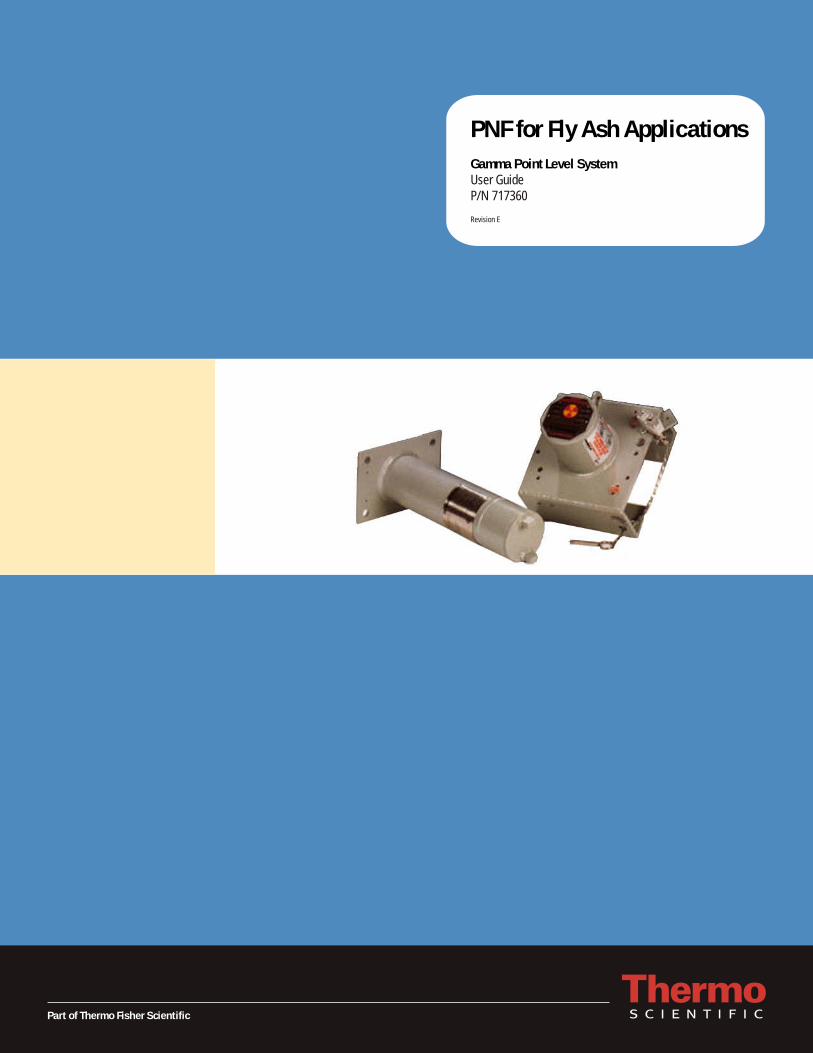
PNF for Fly Ash ApplicationsGamma Point Level SystemUser GuideP/N 717360
Revision E


PNF for Fly Ash ApplicationsGamma Point Level SystemUser GuideP/N 717360
Revision E


© 2011 Thermo Fisher Scientific Inc. All rights reserved.
“Unistrut” is a registered trademark or trademark of Unistrut Corporation and/or its affiliates in the United States and/or other countries. All other trademarks are the property of Thermo Fisher Scientific Inc. and its subsidiaries.
Thermo Fisher Scientific Inc. (Thermo Fisher) makes every effort to ensure the accuracy and completeness of this manual. However, we cannot be responsible for errors, omissions, or any loss of data as the result of errors or omissions. Thermo Fisher reserves the right to make changes to the manual or improvements to the product at any time without notice.
The material in this manual is proprietary and cannot be reproduced in any form without expressed written consent from Thermo Fisher.

This page intentionally left blank.
Thermo Fisher Scientific PNF for Fly Ash Applications v
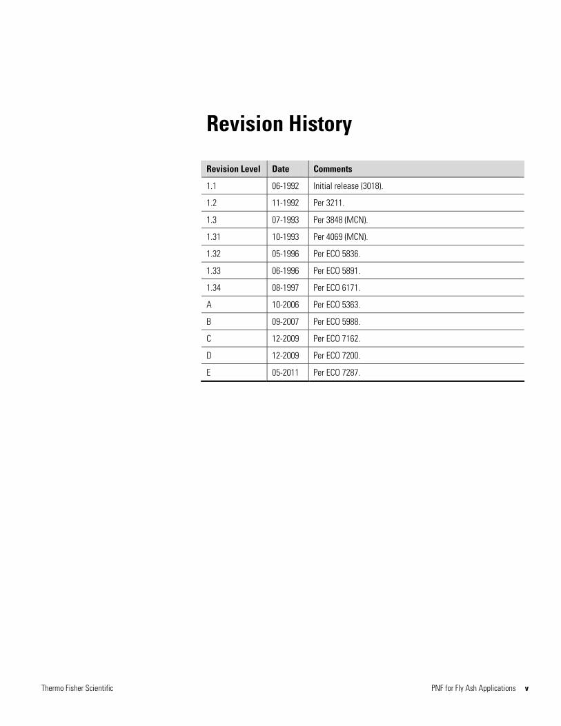
Revision History
Revision Level Date Comments
1.1 06-1992 Initial release (3018).
1.2 11-1992 Per 3211.
1.3 07-1993 Per 3848 (MCN).
1.31 10-1993 Per 4069 (MCN).
1.32 05-1996 Per ECO 5836.
1.33 06-1996 Per ECO 5891.
1.34 08-1997 Per ECO 6171.
A 10-2006 Per ECO 5363.
B 09-2007 Per ECO 5988.
C 12-2009 Per ECO 7162.
D 12-2009 Per ECO 7200.
E 05-2011 Per ECO 7287.

This page intentionally left blank.
Thermo Fisher Scientific PNF for Fly Ash Applications vii
Contents Safety Information .............................................................................................. ix
Safety Considerations .............................................................................ix Safety Summary .....................................................................................ix
Introduction........................................................................................ 1-1 Chapter 1 Product Overview ............................................................................................. 1-1
Additional Documents ........................................................................ 1-3
Regulatory Requirements .................................................................... 2-1
Chapter 2 Licensing ............................................................................................................ 2-1
Uncrating & Inspection.................................................................................... 3-1 Chapter 3
Chapter 4 Vertical Source Head Suspension ................................................................ 4-1
Horizontal Source Head Suspension ............................................................ 5-1 Chapter 5
Suspension of Single Beam Heads ............................................................... 6-1 Chapter 6 Model 5197 Direct Mount ................................................................. 6-2 Model 5197 Channel Reinforced Mount ............................................ 6-3 Model 5200 Mount ............................................................................ 6-3
Chapter 7 Remote Actuator Installation.......................................................................... 7-1
Close-Coupled Actuator Installation ............................................................ 8-1 Chapter 8
Detector Installation ........................................................................................ 9-1 Chapter 9
Chapter 10 Getting Help ..................................................................................................... 10-1 Contact Information ......................................................................... 10-1 Warranty........................................................................................... 10-2

This page intentionally left blank.
Safety Information
This chapter contains information that must be read and understood by all persons installing, using, or maintaining this equipment.
Safety Considerations
ety Considerations
Failure to follow appropriate safety procedures or inappropriate use of the equipment described in this manual can lead to equipment damage or injury to personnel.
Any person working with or on the equipment described in this manual is required to evaluate all functions and operations for potential safety hazards before commencing work. Appropriate precautions must be taken as necessary to prevent potential damage to equipment or injury to personnel.
The information in this manual is designed to aid personnel to correctly and safely install, operate, and/or maintain the system described; however, personnel are still responsible for considering all actions and procedures for potential hazards or conditions that may not have been anticipated in the written procedures. If a procedure cannot be performed safely, it must not be performed until appropriate actions can be taken to ensure the safety of the equipment and personnel. The procedures in this manual are not designed to replace or supersede required or common sense safety practices. All safety warnings listed in any documentation applicable to equipment and parts used in or with the system described in this manual must be read and understood prior to working on or with any part of the system.
Failure to correctly perform the instructions and procedures in this manual or other documents pertaining to this system can result in equipment malfunction, equipment damage, and/or injury to personnel.
Safety Summary Safety Summary The following admonitions are used throughout this manual to alert users to potential hazards or important information. Failure to heed the warnings and cautions in this manual can lead to injury or equipment damage.
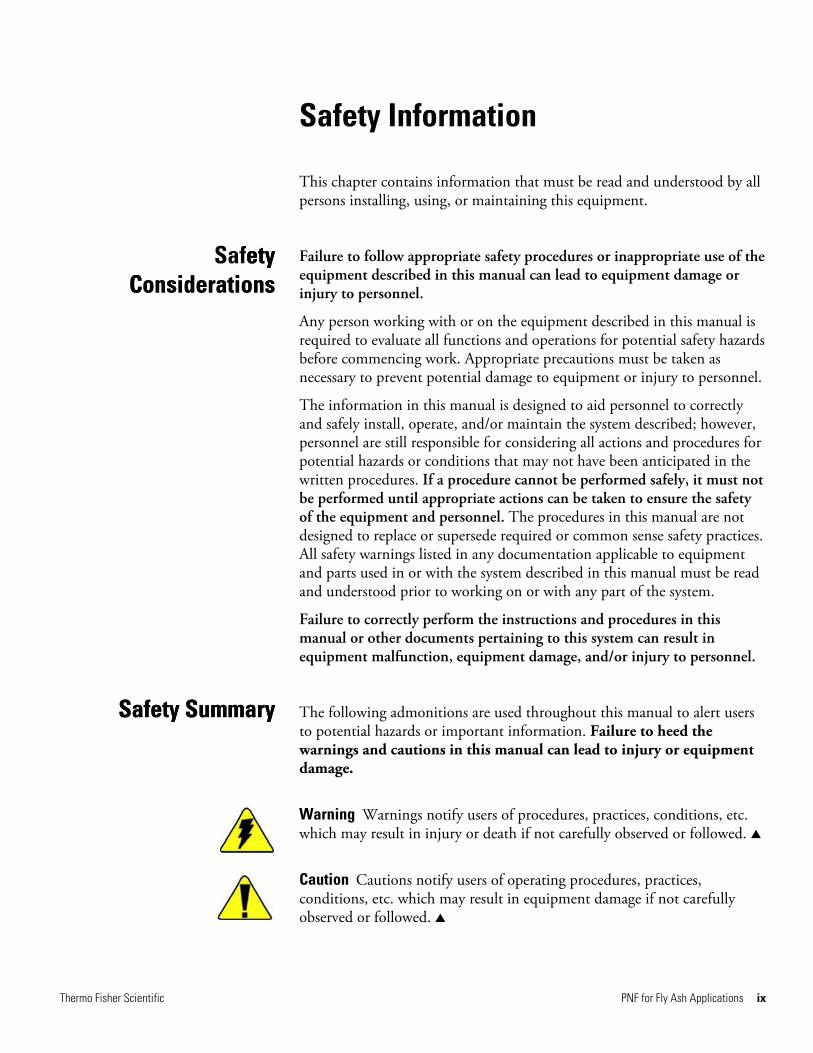
Warning Warnings notify users of procedures, practices, conditions, etc. which may result in injury or death if not carefully observed or followed. ▲
Caution Cautions notify users of operating procedures, practices, conditions, etc. which may result in equipment damage if not carefully observed or followed. ▲
Thermo Fisher Scientific PNF for Fly Ash Applications ix
Safety Information Safety Summary
x PNF for Fly Ash Applications Thermo Fisher Scientific
Note Notes emphasize important or essential information or a statement of company policy regarding an operating procedure, practice, condition, etc. ▲
Chapter 1
Product Overview
Introduction ntroduction This manual pertains to the installation and operation of Thermo Scientific PNF instruments on fly ash hoppers for electrostatic precipitators and bag houses. The instructions in this guide are also applicable to other applications of the Model 5197 dual beam source head. For instructions on other installations, refer to the PNF Installation and Operation Guide, P/N 717640.
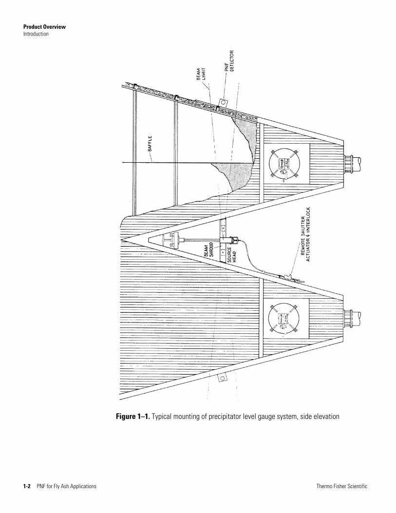
Figure 1–1 shows a typical installation of the Model 5197 source head and two PNF detectors on a pair of fly ash hoppers. The single source head provides the required radiation beams for two hoppers. Lightweight aluminum shrouds prevent access to the beam area. The radiation beams are turned on and off by means of a remote actuator which has provisions for safety locking. In large multiple hopper arrays, the source–detector pairs are horizontally staggered to prevent detector cross talk, that is, to prevent the radiation beams associated with one hopper pair from interfering with those of another hopper pair.
Note Since design, construction, and operating characteristics of plants vary drastically from one installation to another, the user is responsible for choosing the installation technique and the ultimate physical integrity of the installation. Source heads are frequently located over walkways, and thus, the user may wish to take additional precautions such as tying a safety cable from the source head to an independent structural member. Periodic inspection of the source head mounting should be part of normal plant safety inspections. ▲
Thermo Fisher Scientific PNF for Fly Ash Applications 1-1
Product Overview Introduction
Figure 1–1. Typical mounting of precipitator level gauge system, side elevation
1-2 PNF for Fly Ash Applications Thermo Fisher Scientific
Product Overview Additional Documents
Thermo Fisher Scientific PNF for Fly Ash Applications 1-3
Additional Documents
In addition to this guide, the Gamma Radiation Safety Guide (P/N 717904) must be read and understood by all persons installing, using, or maintaining this equipment.

This page intentionally left blank.

Thermo Fisher Scientific PNF for Fly Ash Applications 2-1
Chapter 2
Licensing
Regulatory Requirements
Prior to installing the instrument, refer to the radiation safety guide (P/N 717904) and the following. U. S. Nuclear Regulatory Commission and "Agreement State" regulations and the interpretation thereof cover possession, use, installation, relocation, and service of gauging devices. There are specific authorizations which appear as conditions of licensure and all other actions are prohibited.
These systems are supplied under the provisions of a general license based upon the user supplying an interlock system which positively prohibits access to the interior of the hopper unless the source head is in the OFF position. This is usually accomplished by the use of Kirk or Superior key interlock systems. Under certain carefully prescribed conditions with regard to dose levels on the interior of the hopper, systems may be installed under general license without key interlocks. The conditions under which the Model 5197 source head is distributed permit the user to uncrate and erect the source head, remote actuator, and detectors. These actions are taken with the source head locked in the OFF position by a special Thermo Scientific lock, the key being retained by Thermo Fisher. Completion of the installation, including activation of the source head, can only be done by Thermo Fisher or by someone specifically licensed to install the source heads (with the proper specific license this individual can be the user). Thus, in general, the user can perform the steps in Chapters 3 through 8. The user should then contact Thermo Fisher and schedule a service trip to complete the installation steps described in Chapter 9. If the installation is to be made under the provisions of a general license where interlocks are used as a condition of installation, the entire interlock system must be functional before the system can be activated.

This page intentionally left blank.
Thermo Fisher Scientific PNF for Fly Ash Applications 3-1
Chapter 3
Uncrating & Inspection
Upon receipt, open all shipping boxes and crates and check the equipment for obvious shipping damage. If any damage is visible, contact the carrier and Thermo Fisher.
Ensure the Model 5197 or Model 5200 source head locks are in place. Do not attempt to remove these locks. They will be removed by Thermo Fisher or an individual specifically licensed to do so.
Remove the equipment from the shipping containers and follow the applicable setup instructions provided in the following chapters.

This page intentionally left blank.
Chapter 4
Vertical Source Head Suspension
Reference drawing: 860824
This mounting configuration is generally used where the level measurement is made close to the hopper crotch and where a structural “I” beam is exposed in the crotch. The configuration is also convenient where there is some uncertainty as to the optimum level determination since it allows easy vertical adjustment of the source head. The maximum recommended length of the suspension is 42 inches. Longer suspension is accomplished by following the steps below and referring to Figures 4–1 and 4–2.
1. Determine the beam centerline height and the required offset to prevent detector cross talk. Unless otherwise specified by Thermo Fisher, the offset is equal to 10% of the hopper spacing as shown in the plan view. For example, if the hoppers are on 20-foot centers in the direction of the radiation beam, the offset sources will be alternately 2 feet on either side of the hopper’s centerline.
2. The Unistrut structural material is generally supplied in lengths sufficient to mount two source heads. Determine the “I” beam flange width and cut two pieces of Unistrut to this length. The remaining Unistrut can be cut to the appropriate lengths of the vertical suspension members.
3. Mount the Unistrut support members to the “I” beam flange using the hardware indicated. Tighten all bolts and clamps securely.
4. Mount the Model 5197 source head to the vertical member as shown. Install and tighten the safety bolt at the bottom of the vertical member.
5. Adjust the source head height to the desired level. Be sure that the radiation beam centerline does not intersect stiffeners on the hopper walls or on the baffles.
Thermo Fisher Scientific PNF for Fly Ash Applications 4-1
Vertical Source Head Suspension
6. Install the threaded beam shroud support rod through the holes at the top of the source head. Trim the rod if necessary to clear the hopper lagging. The threaded rod can be used to visually check source head alignment. The rod should be parallel to the hoppers’ centerline; if not, loosen one of the “I” beam clamps slightly and adjust the source head angle. Re-tighten the beam clamp.
7. The source head should be level. Note that the bottom mounting hole in the source head is slotted for leveling adjustments.
8. Cut the aluminum beam shrouds to proper length by trimming the square cut ends. If the installation is being made on hot hoppers, allow sufficient clearance between the shroud and the hopper lagging for contraction of the hopper structure upon cooling.
9. Push the beam shrouds over the spring clips on the source head and secure the shrouds to the threaded support rod with hose clamps as shown.
10. Proceed to installation of the remote actuator in Chapter 7.
4-2 PNF for Fly Ash Applications Thermo Fisher Scientific

Vertical Source Head Suspension
Figure 4–1. Drawing 860824: Vertical mounting, Model 5197 (sheet 1 of 2)
Thermo Fisher Scientific PNF for Fly Ash Applications 4-3
Vertical Source Head Suspension
4-4 PNF for Fly Ash Applications Thermo Fisher Scientific
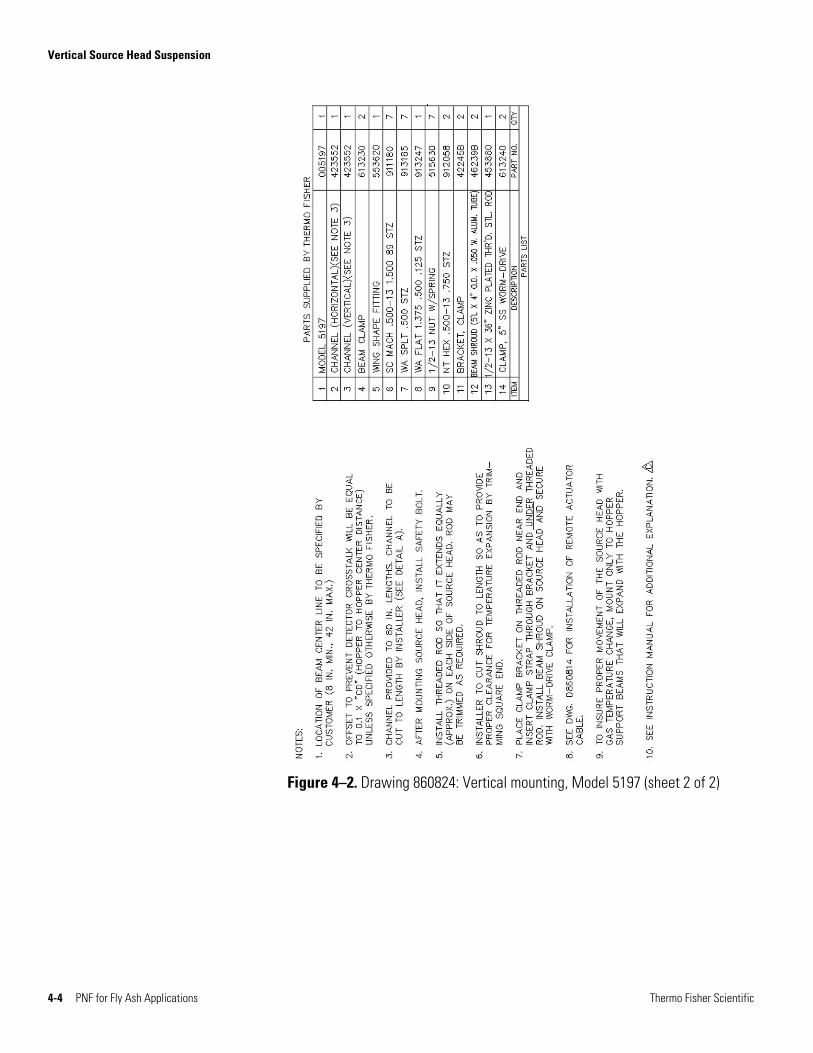
Figure 4–2. Drawing 860824: Vertical mounting, Model 5197 (sheet 2 of 2)
Chapter 5
Horizontal Source Head Suspension
Reference drawing: 860804
The horizontal source head suspension is adaptable to most fly ash hopper installations and is especially suited when large spans are to be covered. Normally the suspension is accomplished by angle brackets which attach directly to the hopper lagging by means of expansion nuts. These brackets are bent to the proper angle for the user’s hoppers. A capstan attachment at one end of the horizontal Unistrut member allows the member to slide during thermal expansion and contraction. Refer to the following steps and Figures 5–1 and 5–2.
1. Determine the beam centerline height and the required offset to prevent detector cross talk. Unless otherwise specified by Thermo Fisher, the offset is equal to 10% of the hopper spacing as shown in the plan view. For example, if the hoppers are on 20-foot centers in the direction of the radiation beam, the offset sources will be alternately 2 feet on either side of the hoppers’ centerline.
Note Be certain that the radiation beam centerline does not intersect stiffeners on the hopper walls or on the baffles. ▲
2. Carefully locate the position of the end mounting angle brackets in relation to the desired radiation beam centerline as shown. Using the brackets as templates, make and drill six 7/16” holes in the hopper lagging for insertion of the expansions nuts.
Note In the case of box ribbed lagging, it will seldom be possible to achieve precise lateral alignment of the two brackets due to offset in the lagging ribs between hoppers. Extra mounting holes for the Unistrut cross members are provided on the bracket to compensate for this misalignment. Do not drill the mounting holes close to the lagging rib edges since this will interfere with proper installation of the expansion nuts. ▲
Thermo Fisher Scientific PNF for Fly Ash Applications 5-1

Horizontal Source Head Suspension
3. Using a Molly hand tool No. 1956-2 with a 1/4-20 pulling rod, install Molly expansion nuts in the mounting holes. Install the end mounting brackets on the lagging with 1/4-20 Sems bolts.
4. Measure the distance XX’ between the two lagging points as indicated. If the distance XX’ is measured with the hoppers cold, cut the horizontal Unistrut member to this length minus three inches. If the distance XX’ is measured with the hoppers at operating temperature, estimate the value of XX’ with cold hoppers using the hopper manufacturer’s expansion data.
5. Lay the horizontal Unistrut member on the supporting angle brackets and determine which angle bracket bolt holes will be used to give the best parallel alignment for the Unistrut with the hopper centerline.
6. Remove the horizontal Unistrut member and install the capstan assembly in one of the outer bracket holes previously selected. Refer to Section A-A of the drawing.
7. Install the 90° hanging fixtures on the source head. The long leg of the fixture attaches to the source head.
8. Lay the horizontal Unistrut member on the floor, open side up, and attach the source head securely in the center of the bracket. Do not attach beam shrouds at this time.
9. Slide the Unistrut/source head assembly over the previously installed capstan and attach the fixed end of the Unistrut to the previously selected holes on the mounting bracket. Ensure that there is sufficient overlap at the free end of the horizontal member so that the capstan will retain the Unistrut after thermal expansion. Tighten all bolts.
10. Trim the square cut ends of the beam shroud to give minimal clearance between the shroud and the hopper lagging. If the installation is made on hot hoppers, be sure to allow sufficient clearance for hopper contraction on the free end. Slide the shrouds over the spring clips on the source head and install mounting hangers as shown.
5-2 PNF for Fly Ash Applications Thermo Fisher Scientific
Horizontal Source Head Suspension
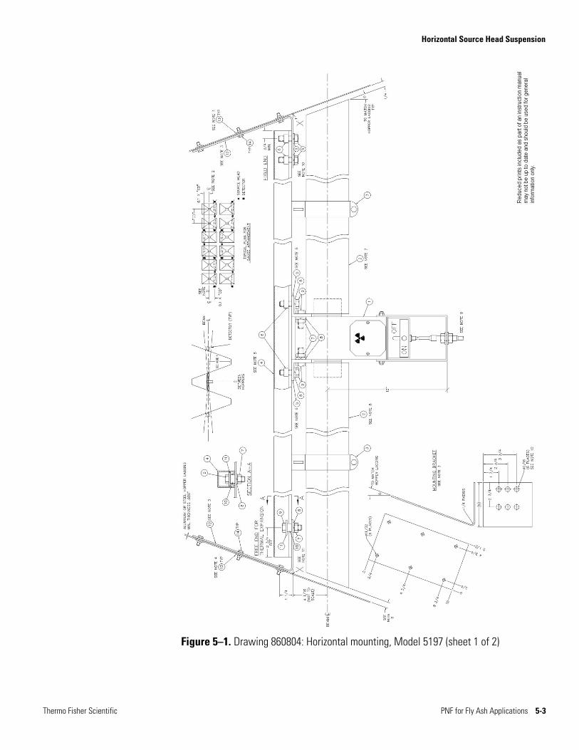
Figure 5–1. Drawing 860804: Horizontal mounting, Model 5197 (sheet 1 of 2)
Thermo Fisher Scientific PNF for Fly Ash Applications 5-3

Horizontal Source Head Suspension
5-4 PNF for Fly Ash Applications Thermo Fisher Scientific
Figure 5–2. Drawing 860804: Horizontal mounting, Model 5197 (sheet 2 of 2)
Chapter 6
Suspension of Single Beam Heads
Reference drawings: 862254, 862244, 866264, 866114
In arrangements containing an odd number of hoppers, it is usually necessary to use some combination of dual and single beam heads. In certain special cases the installation may use all single beam heads. When the Model 5197 source head is used in single beam applications, it is simply plugged on one side, either at the factory or by Thermo Fisher at the time of final installation. The Model 5200 source head is used in some instances where larger sources are required.
The referenced drawings show two methods of mounting the Model 5197 for single beam application. In the first, the source head support angle bracket is simply Molly bolted to the hopper lagging. This method is satisfactory for corrugated aluminum laggings of a thickness not less than .030 inches and where the lagging is well secured to the hopper structure and not subject to severe vibration which could work harden the aluminum. This type of support has been tested by Thermo Fisher to loads of 200 pounds (about 5 times the source head load) without evidence of lagging deformation.
A second operation is the channel reinforced mounting which is recommended for lighter weight or non-corrugated laggings, installations where the lagging support is questionable, or where hopper vibrations are used on a regular basis. The channel reinforced mounting also allows easy readjustment of the beam centerline should this be necessary. The pre-drilled reinforcing channels may be mounted at multiple points to the hopper lagging or may be secured to the hopper stiffeners or other structural components.
The source head shielding is designed for personnel protection, but because of the extreme sensitivity of the PNF detectors, normal radiation leakage from a source head may be sufficient to activate a nearby detector. Thus, certain minimum distances must be maintained between source heads and detectors on adjacent hopper. The reference drawing includes a table showing minimum separation distances for various source sizes according to two installation schemes.
Thermo Fisher Scientific PNF for Fly Ash Applications 6-1
Suspension of Single Beam Heads Model 5197 Direct Mount
The “in line” scheme is simplest, but the required source head-detector separations may not be compatible with the hopper dimensions and the desired beam height. In such cases it is suggested that the “45° offset” be used. The 45° angle not only increases the separation but also maximizes the shielding effect of a square source head. If the desired installation does not allow these angles and distances to be maintained, consult Thermo Fisher for other angles or special source shielding that may be used.
Model 5197 Direct Mount
Reference drawing: 862254
1. Determine the beam centerline height and the required separation and offset to prevent interference between the detectors and the adjacent source heads. Ensure that the beam centerline does not intersect hopper stiffeners.
2. Locate the position of the mounting bracket in relation to the desired radiation beam centerline as shown. Using the bracket as a template, mark and drill eight 7/16” holes in the hopper lagging for insertion of the expansion nuts. Do not drill the mounting holes close to the lagging rib edges since this will interfere with proper installation of the expansion nuts.
3. Using a Molly hand tool number 1956-2 with a 1/4-20 pulling rod, install Molly expansion nuts in the mounting holes. Install the source head mounting bracket on the lagging with 1/4-20 Sems bolts.
4. Bolt the 90° hangers to the source head. The long leg of the hanger attaches to the source head.
5. Bolt the source head loosely to the lagging support bracket and push the aluminum beam shroud over the spring clip. If necessary, spread the clip ears slightly to ensure that the shroud is securely held. Then temporarily tighten the source head mounting bolts.
6. Using a spirit level, determine that the source head is hanging vertically so that the beam path will be level or nearly so through the hopper. If necessary, level the head by using flat washers between the 90° hanging brackets and the lagging mounting bracket. Then securely tighten the head.
6-2 PNF for Fly Ash Applications Thermo Fisher Scientific
Suspension of Single Beam Heads Model 5197 Channel Reinforced Mount
Model 5197 Channel Reinforced Mount
Reference drawing: 862244
1. Determine the beam centerline height and the required separation and offset to prevent interference between the detectors and the adjacent source heads. Ensure that the beam centerline does not intersect hopper stiffeners.
2. Attach the Unistrut channels to the hopper lagging on 4-inch centers as shown. If the lagging has standard 4-inch pitch corrugation, it is desirable to lay the Unistrut in the valleys of the corrugations. Attachment to the lagging is usually by means of Molly expansion nuts. Drill up to eight 7/16” holes per channel in the hopper lagging and install the expansion nuts in the mounting holes with Molly hand tool number 1956-2 with a 1/4-20 pulling rod. Attach the channels with 1/4-20 Sems bolts and flat washers. According to the particular installation, it may be desirable to further anchor the channels to hopper stiffeners or other structural members.
3. Attach the source head mounting bracket to the channels at the appropriate height by means of the four Unistrut spring nuts and 1/4-20 Sems bolts.
4. Complete the source head installation by following steps 4 through 6 of the above section, “Model 5197 Direct Mount.”
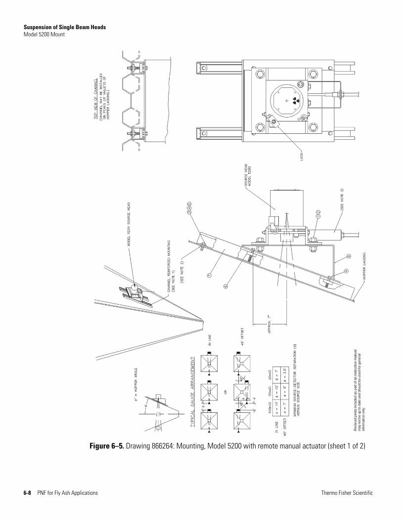
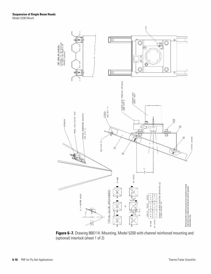
Model 5200 Mount Reference drawing: 866264, 866114
The Model 5200 source head is supplied in certain cases where larger sources are needed. Since the Model 5200 is heavier than the Model 5197, direct mounting to the lagging is not suitable and a channel reinforced mounting is recommended. See the reference drawings.
Thermo Fisher Scientific PNF for Fly Ash Applications 6-3
Suspension of Single Beam Heads Model 5200 Mount
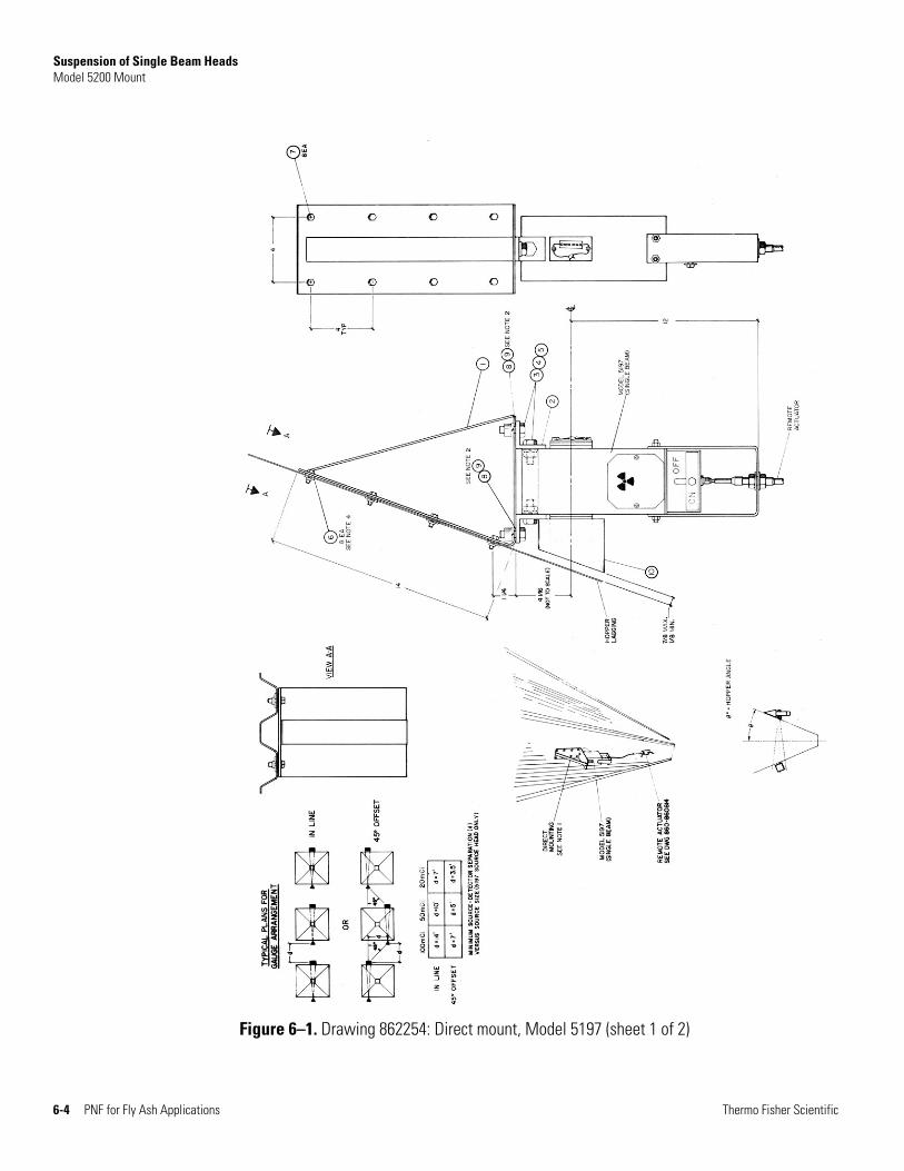
Figure 6–1. Drawing 862254: Direct mount, Model 5197 (sheet 1 of 2)
6-4 PNF for Fly Ash Applications Thermo Fisher Scientific
Suspension of Single Beam Heads Model 5200 Mount
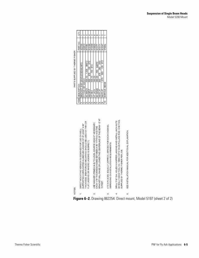
Figure 6–2. Drawing 862254: Direct mount, Model 5197 (sheet 2 of 2)
Thermo Fisher Scientific PNF for Fly Ash Applications 6-5
Suspension of Single Beam Heads Model 5200 Mount
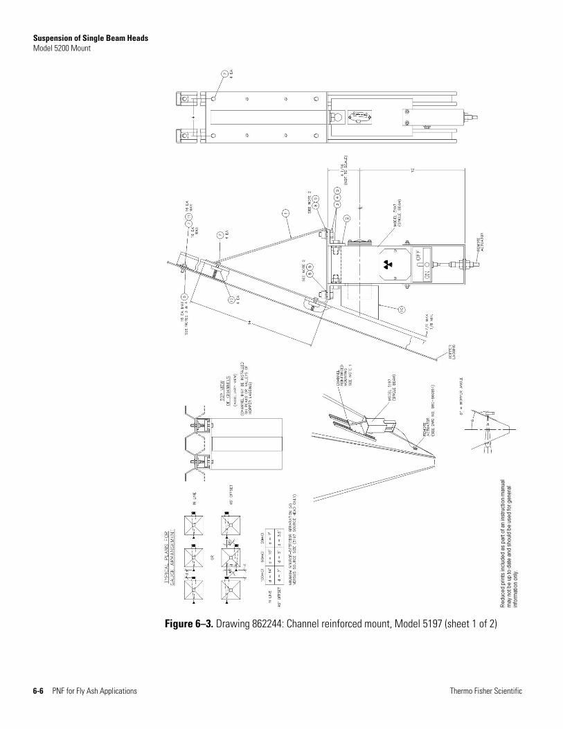
Figure 6–3. Drawing 862244: Channel reinforced mount, Model 5197 (sheet 1 of 2)
6-6 PNF for Fly Ash Applications Thermo Fisher Scientific

Suspension of Single Beam Heads Model 5200 Mount
Figure 6–4. Drawing 862244: Channel reinforced mount, Model 5197 (sheet 2 of 2)
Thermo Fisher Scientific PNF for Fly Ash Applications 6-7
Suspension of Single Beam Heads Model 5200 Mount
Figure 6–5. Drawing 866264: Mounting, Model 5200 with remote manual actuator (sheet 1 of 2)
6-8 PNF for Fly Ash Applications Thermo Fisher Scientific
Suspension of Single Beam Heads Model 5200 Mount
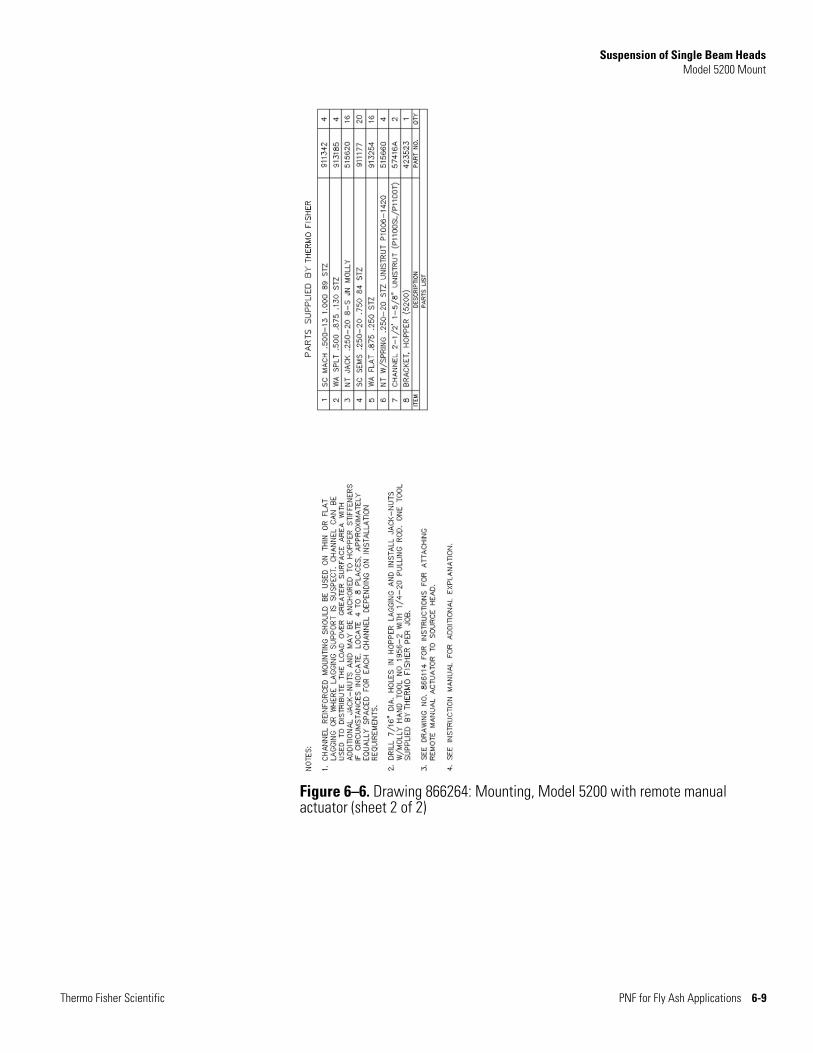
Figure 6–6. Drawing 866264: Mounting, Model 5200 with remote manual actuator (sheet 2 of 2)
Thermo Fisher Scientific PNF for Fly Ash Applications 6-9
Suspension of Single Beam Heads Model 5200 Mount
Figure 6–7. Drawing 866114: Mounting, Model 5200 with channel reinforced mounting and (optional) interlock (sheet 1 of 2)
6-10 PNF for Fly Ash Applications Thermo Fisher Scientific
Suspension of Single Beam Heads Model 5200 Mount
Thermo Fisher Scientific PNF for Fly Ash Applications 6-11
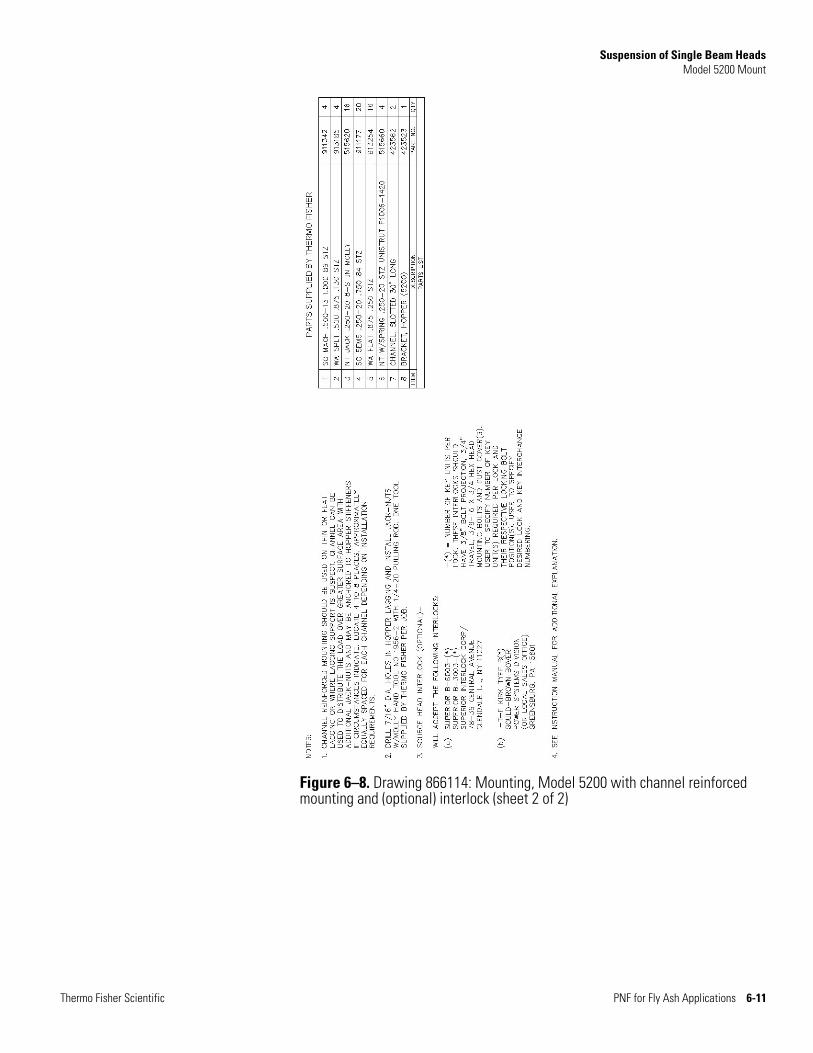
Figure 6–8. Drawing 866114: Mounting, Model 5200 with channel reinforced mounting and (optional) interlock (sheet 2 of 2)

This page intentionally left blank.
Chapter 7
Remote Actuator Installation
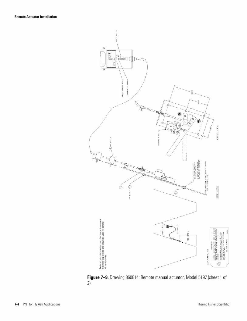
Reference drawing: 860814
Only Thermo Fisher should install the remote shutter actuator cable. When handling the actuators during unpacking and installation, be very careful to avoid kinking the cable. A general licensee should not perform any work on the source head. A specific licensee must be authorized by license to perform maintenance and/or repair on the source head.
1. Locate the actuator at a convenient point on the hopper lagging. If at all possible, the ON/OFF indicator on the source head should be visible from the actuator position.
2. Using the actuator as a template, locate and drill six 7/16” holes in the hopper lagging for installation of the expansion nuts.
3. Using Molly hand tool 1956-2 with a 1/4-20 pulling rod, install Molly expansion nuts in the lagging holes.
4. Attach the actuator plate with 1/4-20 Sems bolts.
5. Temporarily attach the free end of the actuator cable to the source head bracket, training the cable end to the side of the source holder rod as shown. Do not attempt to thread the cable end into the source holder rod. This will be done at final installation.
6. Secure the cable to the hopper lagging at two or three points using vinyl coated clips and sheet metal screws. Ensure that the bend radius of the cable is always greater than one foot.
Thermo Fisher Scientific PNF for Fly Ash Applications 7-1
Remote Actuator Installation
7. Install Kirk or Superior interlocks on the side of the aluminum lock block (it may be desirable to delay this step until final installation). If key interlocks are not to be used in the installation, the lock block will be drilled for a padlock in the OFF position.
Caution Only Thermo Fisher or an individual specifically licensed to install the source head may perform the following steps. ▲
8. Place the handle of the close-coupled actuator in the OFF (down) position.
9. Remove the Thermo Scientific safety lock.
10. The travel of the source holder rod is limited in the ON and OFF positions by the travel of the bolt in the milled slot of the ON/OFF plate. While moving the handle of the close-coupled actuator to its extreme positions, note the travel of the bolt in the milled slot. In the OFF position, the bolt should just rest at the bottom of the milled slot without excessive tension on the cable. In the ON position, the bolt should travel fully to the top of the milled slot and the override plunger should depress slightly into the source holder rod. Small adjustments in the travel can be made by threading the override plunger on or off of the cable end. When the travel is satisfactory, tighten the lock nut against the override plunger.
11. Inspect all mounting hardware for proper and complete installation.
12. Survey the source head in the ON and OFF conditions and record the data. Perform the required leak test.
13. With the source head ON, measure the radiation level from the detector sides of the hoppers for proper intensity. If the detectors have not been located, make the beam centerline on the hopper sides. If the detectors have already been mounted, check their location for proper relationship to the beam and verify operation.
7-2 PNF for Fly Ash Applications Thermo Fisher Scientific
Remote Actuator Installation
Caution If the installation is under the provisions of a General License where interlocks are to be used, ensure that the entire interlock system is functional. If the installation is under General License without interlocks, ensure that radiation levels are within prescribed limits, installing radiation shims if necessary. Ensure that a sign is attached to each hopper access door warning the user to turn the source head OFF and padlock the actuator before entering the hopper. ▲
14. Make sure that the customer is properly instructed on gauge operation, safety, and regulatory requirements. This completes commissioning of the system.
Thermo Fisher Scientific PNF for Fly Ash Applications 7-3
Remote Actuator Installation
Figure 7–9. Drawing 860814: Remote manual actuator, Model 5197 (sheet 1 of 2)
7-4 PNF for Fly Ash Applications Thermo Fisher Scientific
Remote Actuator Installation
Thermo Fisher Scientific PNF for Fly Ash Applications 7-5
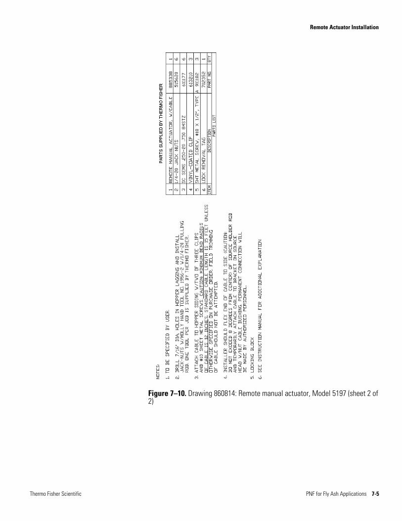
Figure 7–10. Drawing 860814: Remote manual actuator, Model 5197 (sheet 2 of 2)

This page intentionally left blank.
Chapter 8
Close-Coupled Actuator Installation
Reference drawing: 868155
The close-coupled actuator is shipped unattached to the Model 5197 source head. The actuator assembly should not be installed or adjusted except by Thermo Fisher. When handling the actuators during unpacking and storage, be very careful not to damage the threads on the rod.
1. Install Kirk or Superior interlocks on the side of the aluminum lock block (it may be desirable to delay this step until final installation). If key interlocks are not to be used in the installation, the lock block will be drilled for a padlock in the OFF position.
Caution Only Thermo Fisher or an individual specifically licensed to install the Model 5197 source head may perform the following steps. ▲
2. Place the handle of the close-coupled actuator in the OFF (down) position.
3. While supporting the close-coupled actuator, thread the override plunger of the source holder rod onto the threaded rod of the actuator until the mounting holes of the actuator bracket (the U-shaped part) line up with the mounting holes on the source head. Ensure the source holder connector (the piece that connects the source holder to the threaded rod) remains directly in line with the source holder and the rod with a minimum of play in any direction.
4. Secure the close-coupled actuator to the source head using four 1/4-20 x 3/4 hex head bolts and 1/4-20 nuts.
5. Remove the Thermo Scientific safety lock.
Thermo Fisher Scientific PNF for Fly Ash Applications 8-1
Close-Coupled Actuator Installation
6. The travel of the source holder rod is limited in the ON and OFF positions by the travel of the bolt in the milled slot of the ON/OFF plate. While moving the handle of the close-coupled actuator to its extreme position, note the travel of the bolt in the milled slot. In the OFF position, the bolt should just rest at the bottom of the milled slot without excessive tension on the rod. In the ON position, the bolt should travel fully to the top of the milled slot, and the override plunger should depress slightly into the source holder rod. Small adjustments in the travel can be made by threading the override plunger on or off of the threaded rod. When the travel is satisfactory, tighten the lock nut against the override plunger.
7. Inspect all mounting hardware for proper and complete installation.
8. Survey the source head in the ON and OFF conditions and record the data. Perform the required leak test.
9. With the source head ON, measure the radiation level from the detector sides of the hoppers for proper intensity. If the detectors have not been located, mark the beam centerline on the hopper sides. If the detectors have already been mounted, check for proper relationship to the beam and verify operation.
Caution If the installation is under the provisions of a General License where interlocks are to be used, ensure that the entire interlock system is functional. If the installation is under General License without interlocks, ensure that radiation levels are within prescribed limits, installing radiation shims if necessary. Ensure that a sign is attached to each hopper access door warning the user to turn the source head OFF and padlock the actuator before entering the hopper. ▲
10. Make sure that the customer is properly instructed on gauge operation, safety, and regulatory requirements. This completes commissioning of the system.
8-2 PNF for Fly Ash Applications Thermo Fisher Scientific
Close-Coupled Actuator Installation
Thermo Fisher Scientific PNF for Fly Ash Applications 8-3
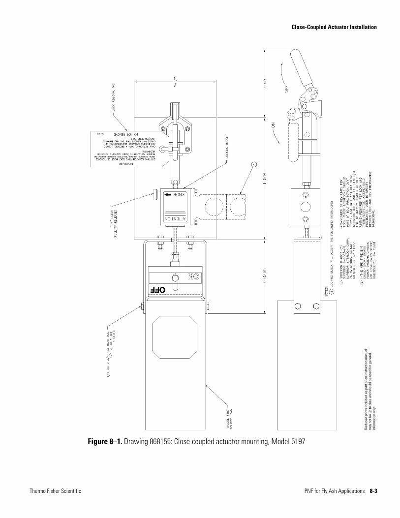
Figure 8–1. Drawing 868155: Close-coupled actuator mounting, Model 5197

This page intentionally left blank.
Chapter 9
Detector Installation
Reference drawings: 860764, 868565
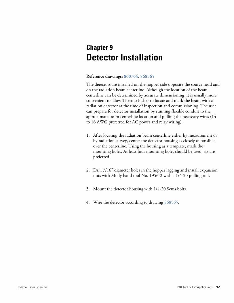
The detectors are installed on the hopper side opposite the source head and on the radiation beam centerline. Although the location of the beam centerline can be determined by accurate dimensioning, it is usually more convenient to allow Thermo Fisher to locate and mark the beam with a radiation detector at the time of inspection and commissioning. The user can prepare for detector installation by running flexible conduit to the approximate beam centerline location and pulling the necessary wires (14 to 16 AWG preferred for AC power and relay wiring).
1. After locating the radiation beam centerline either by measurement or by radiation survey, center the detector housing as closely as possible over the centerline. Using the housing as a template, mark the mounting holes. At least four mounting holes should be used; six are preferred.
2. Drill 7/16" diameter holes in the hopper lagging and install expansion nuts with Molly hand tool No. 1956-2 with a 1/4-20 pulling rod.
3. Mount the detector housing with 1/4-20 Sems bolts.
4. Wire the detector according to drawing 868565.
Thermo Fisher Scientific PNF for Fly Ash Applications 9-1
Detector Installation
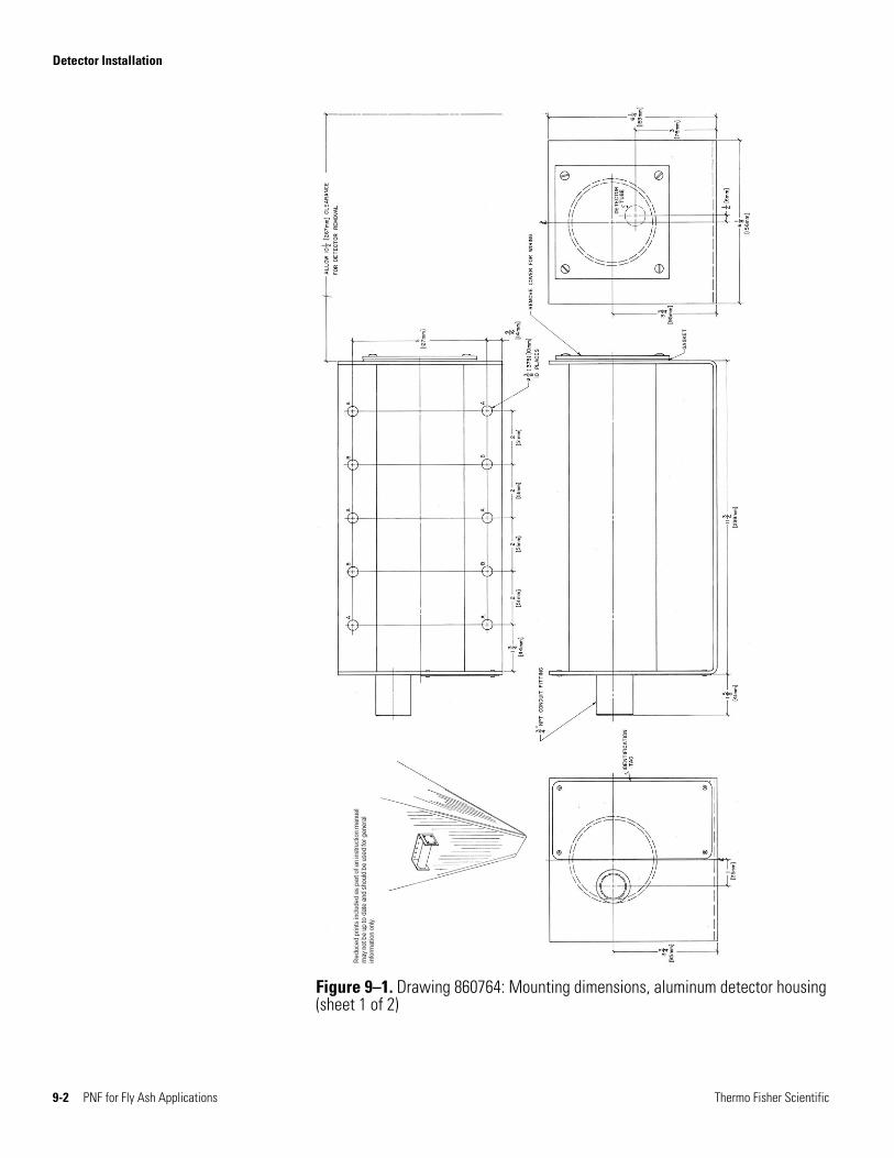
Figure 9–1. Drawing 860764: Mounting dimensions, aluminum detector housing (sheet 1 of 2)
9-2 PNF for Fly Ash Applications Thermo Fisher Scientific
Detector Installation
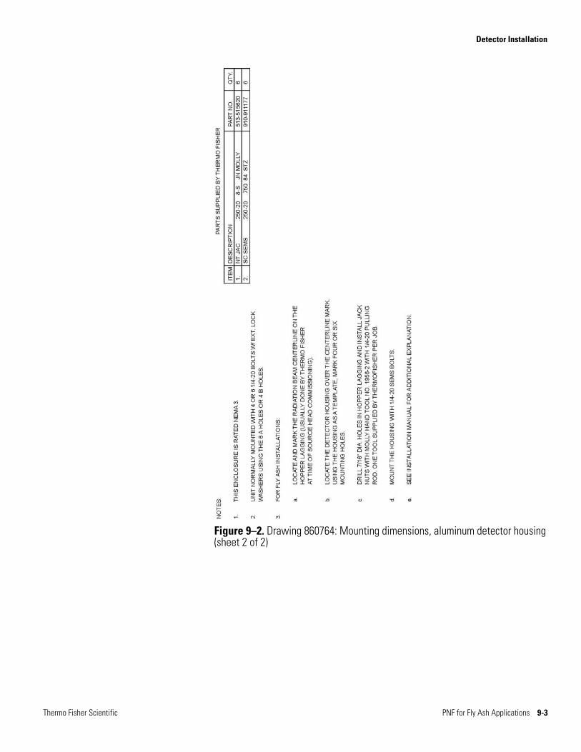
Figure 9–2. Drawing 860764: Mounting dimensions, aluminum detector housing (sheet 2 of 2)
Thermo Fisher Scientific PNF for Fly Ash Applications 9-3
Detector Installation
9-4 PNF for Fly Ash Applications Thermo Fisher Scientific
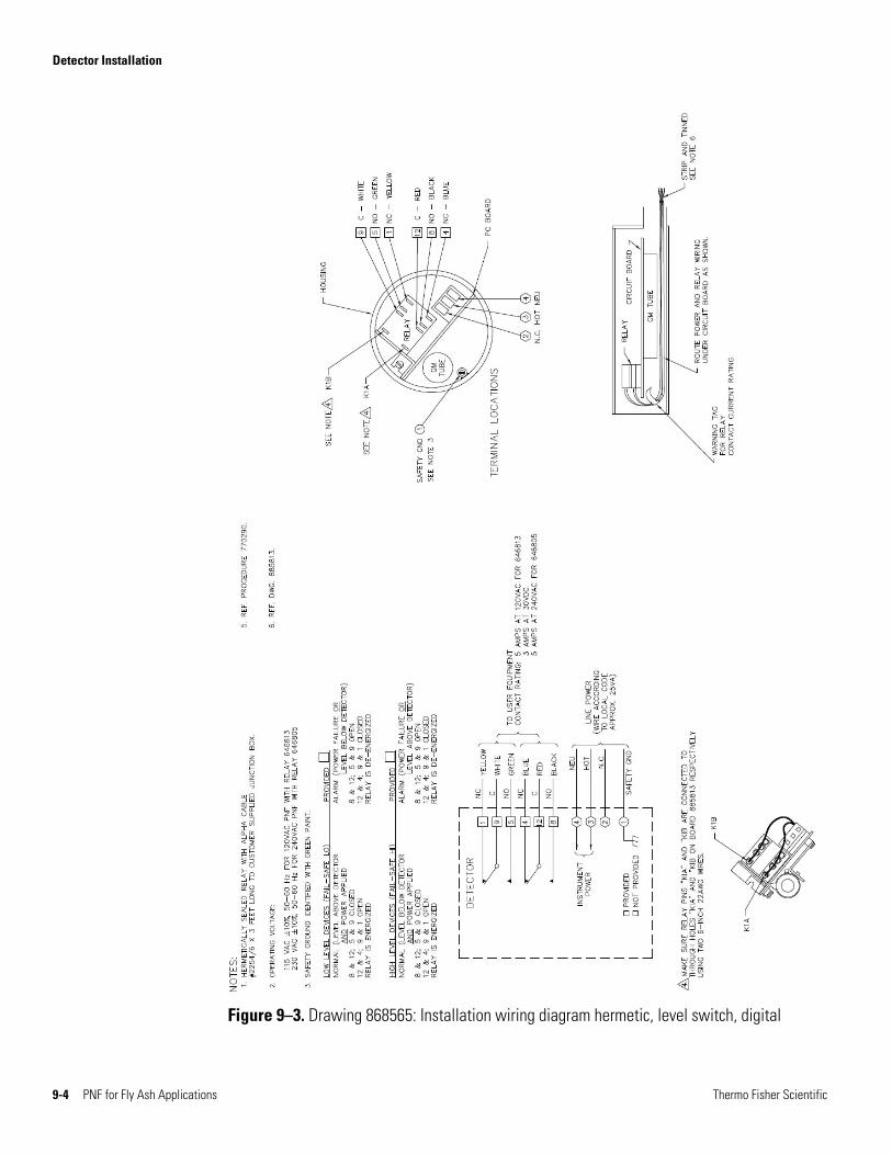
Figure 9–3. Drawing 868565: Installation wiring diagram hermetic, level switch, digital
Chapter 10
Getting Help
Contact Information
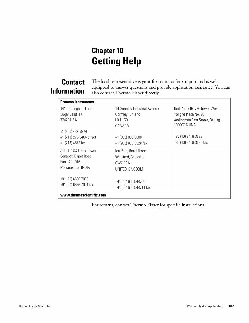
The local representative is your first contact for support and is well equipped to answer questions and provide application assistance. You can also contact Thermo Fisher directly.
Process Instruments
1410 Gillingham Lane Sugar Land, TX 77478 USA +1 (800) 437-7979 +1 (713) 272-0404 direct +1 (713) 4573 fax
14 Gormley Industrial Avenue Gormley, Ontario L0H 1G0 CANADA +1 (905) 888-8808 +1 (905) 888-8828 fax
Unit 702-715, 7/F Tower West Yonghe Plaza No. 28 Andingmen East Street, Beijing 100007 CHINA +86 (10) 8419-3588 +86 (10) 8419-3580 fax
A-101, 1CC Trade Tower Senapati Bapat Road Pune 411 016 Maharashtra, INDIA +91 (20) 6626 7000 +91 (20) 6626 7001 fax
Ion Path, Road Three Winsford, Cheshire CW7 3GA UNITED KINGDOM +44 (0) 1606 548700 +44 (0) 1606 548711 fax
www.thermoscientific.com
For returns, contact Thermo Fisher for specific instructions.
Thermo Fisher Scientific PNF for Fly Ash Applications 10-1

Getting Help Warranty
10-2 PNF for Fly Ash Applications Thermo Fisher Scientific
Warranty Thermo Scientific products are warranted to be free from defects in material and workmanship at the time of shipment and for one year thereafter. Any claimed defects in Thermo Scientific products must be reported within the warranty period. Thermo Fisher shall have the right to inspect such products at Buyer’s plant or to require Buyer to return such products to Thermo Fisher plant.
In the event Thermo Fisher requests return of its products, Buyer shall ship with transportation charges paid by the Buyer to Thermo Fisher plant. Shipment of repaired or replacement goods from Thermo Fisher plant shall be F.O.B. Thermo Fisher plant. A quotation of proposed work will be sent to the customer. Thermo Fisher shall be liable only to replace or repair, at its option, free of charge, products which are found by Thermo Fisher to be defective in material or workmanship, and which are reported to Thermo Fisher within the warranty period as provided above. This right to replacement shall be Buyer’s exclusive remedy against Thermo Fisher.
Thermo Fisher shall not be liable for labor charges or other losses or damages of any kind or description, including but not limited to, incidental, special or consequential damages caused by defective products. This warranty shall be void if recommendations provided by Thermo Fisher or its Sales Representatives are not followed concerning methods of operation, usage and storage or exposure to harsh conditions.
Materials and/or products furnished to Thermo Fisher by other suppliers shall carry no warranty except such suppliers’ warranties as to materials and workmanship. Thermo Fisher disclaims all warranties, expressed or implied, with respect to such products.
EXCEPT AS OTHERWISE AGREED TO IN WRITING BY Thermo Fisher, THE WARRANTIES GIVEN ABOVE ARE IN LIEU OF ALL OTHER WARRANTIES, EXPRESSED OR IMPLIED, AND Thermo Fisher HEREBY DISCLAIMS ALL OTHER WARRANTIES, INCLUDING THOSE OF MERCHANTABILITY AND FITNESS FOR PURPOSE.

Thermo Fisher Scientific81 Wyman StreetP.O. Box 9046Waltham, Massachusetts 02454-9046United States
www.thermofisher.com