guide plane retention in removable partial …
TRANSCRIPT

GUIDE PLANE RETENTION IN
REMOVABLE PARTIAL DENTURES
Dr Matshediso M Mothopi
A research report submitted for partial completion of Masters in
Dentistry in Prosthodontics
1
Declaration
I, MATSHEDISO MARIA MOTHOPI declare that this research report is my own
work. It is being submitted for the degree of Master of Dentistry in the University of the
Witwatersrand, Johannesburg. It has not been submitted before for any degree or
examination at this or any other University.
Signed …………………………………………
06 December 2011

2
Dedication
I dedicate this research report to my family, especially my daughter Palesa whom at a
tender age of nine continues to be an inspiration in everything I do. Also to my elderly
patients who are forever grateful for our services and in this instance were the main
driving forces for this research project.

3
Acknowledgements
Prof CP Owen (BDS, MScDent, MDent, FICD) for being my best teacher of all times.
His supervision, support and encouragement have made this research report possible.
Mr Johan Booyzen for his advice and assistance in laboratory procedures.
Mr Wayne Costopoulus and Andrew Heydemrych (Civil and Environmental
Engineering Department, University of the Witwatersrand) for their help with the
custom made jig and other measurement accessories.
Dr Noland Naidoo and Michael Peri for their support and assistance in taking the
measurements.
Mr Dion Van Zyl for the statistical analysis of the data.
My fellow registrars and staff in the Department of Prosthodontics for their support,
understanding and assistance in many other ways.

4
Abstract
Purpose
The purpose of this study was to measure and compare the influence of abutment teeth
guide planes and partial denture guiding surfaces on the retention of removable partial
dentures.
Method
An upper typodont model was modified by removing both second premolars and first
molars, thus creating two bounded saddles. An impression of the model was made with
irreversible hydrocolloid and a cast poured, on which an acrylic resin based removable
partial denture (RPD) was made. To this denture a hooking device was added so that the
model and denture could be placed on a custom-made platform and jig on a universal
testing machine (Instron, UK). The RPD was then removed from the model along its
path of insertion (perpendicular to the occlusal plane) as well as at 2° and 5° and the
maximum load recorded. The typodont model was then modified by making guide
planes on the abutment teeth, and a second RPD made and the procedure repeated. This
RPD was then modified by creating guiding surfaces directly against the guide planes
using autopolymerising resin, and the procedure again repeated. Each measurement was
made 10 times at each path of insertion/withdrawal, resulting in 90 measurements.
Results
There were some differences between the different paths of withdrawal in each of the
three situations, explicable by the lack of ideal contact in the first two dentures, and the
much improved contact in the third, which caused the teeth in the model to move on
withdrawal. Overall, there were significant differences between the three models. There

5
was a significant increase in retentive force of 1.6 times from denture 1 to denture 2, of
7.6 times from denture 2 to denture 3, and 12.3 times from denture 1 to denture 3.
Conclusion
This study confirmed that guide planes increase the retention of an RPD, but that when
guiding surfaces of the denture are adapted closely to the guide planes on the teeth,
there is a considerable increase in retention.

6
Table of Contents Abstract ......................................................................................................................................... 4
List of Figures ................................................................................................................................ 7
List of Tables .................................................................................................................................. 8
1 Introduction and Literature review ....................................................................................... 9
2 Aims and Objectives ............................................................................................................ 13
2.1 Aim .............................................................................................................................. 13
2.2 Objectives .................................................................................................................... 13
3 Methodology ....................................................................................................................... 14
3.1 Study Design ................................................................................................................ 14
3.2 Sample Size .................................................................................................................. 14
3.3 Materials and Methods ............................................................................................... 14
3.4 Analysis ........................................................................................................................ 18
3.5 Study validity and reliability ........................................................................................ 19
4 Results ................................................................................................................................. 20
4.1 Model 1, Denture 1: no guide planes or surfaces ....................................................... 20
4.1.1 Denture at 0° ...................................................................................................... 20
4.1.2 All degrees for Model 1 ....................................................................................... 21
4.2 Model 2, Denture 2: guide planes on the teeth, no guiding surfaces on the denture 22
4.3 Model 2, Denture 3: guide planes on the teeth, and guiding surfaces on the denture
22
4.4 Comparisons between all the dentures ...................................................................... 23
5 Discussion ............................................................................................................................ 24
Limitations and opportunities ................................................................................................. 28
6 Conclusions ......................................................................................................................... 30
7 References ........................................................................................................................... 31
8 APPENDIX 1. Graphs and tables from the tensile testing machine ..................................... 34
9 APPENDIX 2. Statistical tests ............................................................................................... 43

7
List of Figures
Figure 1 The typodont model simulating the clinical situation of two bounded saddles. .......... 15
Figure 2 Acrylic partial denture with hooking device to enable placement in a universal testing
machine. ...................................................................................................................................... 16
Figure 3 Side view of lower jig made to take a model platform from a model surveyor. .......... 16
Figure 4 Calibrated mechanism to provide tilt to vary the path of insertion/withdrawal. ........ 16
Figure 5 Typodont model on custom-made platform on universal testing machine with hook in
place on upper jig. ....................................................................................................................... 16
Figure 6 Preparation of guide planes on the typodont model. ................................................... 17
Figure 7 Occlusal view of the prepared guide planes. ................................................................ 17
Figure 8 Load vs extension graph at 0⁰ for denture 1. The graphs were modified by offsetting
each subsequent test in order to make the graph more readable. ............................................ 20

8
List of Tables
Table 1. Loads at 0⁰ for denture 1 ............................................................................................... 21
Table 2. Results for Model 1, denture 1. Figures in red are statistically significant at p<0.05 ... 21
Table 3. Results for Model 2, denture 2. Figures in red are statistically significant at p<0.05 ... 22
Table 4. Results for Model 2, denture 3. Figures in red are statistically significant at p<0.05 ... 22
Table 5. Results for all dentures at 0⁰. Figures in red are statistically significant at p<0.05 ...... 23

9
1 Introduction and Literature review
An increase in life expectancy in populations around the world is expected to result in
an increase in partially dentate individuals as people retain their teeth for a longer period
of time (Marcus et.al., 1996; Zwetchkenbaum and Shay, 1997). Removable partial
denture (RPD) rehabilitation is expected to increase with this increase in partial
edentulism. To be able to service these patients satisfactorily it is necessary to plan,
design and construct RPDs with care.
The use of RPDs is extensive in both general dental practice as well as in a specialist
setting. RPDs are important for improving partially dentate patient‟s aesthetics, speech,
function, and load distribution. They are also used in cases where there have been
drifting and tilting of teeth and also where patients have lost vertical dimension and
alveolar bone due to tooth loss (Owen, 2000). Unfortunately despite all these
advantages RPDs have always been associated with problems which sometimes lead to
patients not wearing them. Poor fit, difficulty to manipulate the denture, and plaque
accumulation are some of the problems that are often encountered (MacEntee, 2011).
Several studies (Brudvik and Reimers, 1992; Stern, Brudvik and Frank, 1985) reported
that the majority of finished partial denture frameworks were found to be poorly fitting
onto the abutment teeth. The components of the partial dentures were found to not be as
close fitting to the abutment teeth as they should be, therefore leading to the denture
dislodging quite easily. Frank et al (2000) reported that patients who were not satisfied
with their RPDs (76%) reported the main cause to be lack of fit.

10
The aim of this study is to investigate the effect of guideplanes and modified guiding
surfaces on RPD retention. The guide/guiding planes are defined as “vertically parallel
surfaces on abutment teeth oriented so as to contribute to the direction of the path of
placement and removal of a removable dental prosthesis” (GPT 8). The guide/guiding
plate or surface is “that component of a RPD framework that is the counterpart of a
guide plane” (NaBadalung, Nichols and Brudvick, 1997).
The functions of guide planes have been mentioned as “1) providing one path of
placement/removal of a prosthesis thereby eliminating excessive stress upon either the
restoration or the abutment teeth; 2) ensuring the intended action of various
reciprocating, stabilizing and retentive components; 3) aiding with retention against
dislodging forces other than those acting parallel to a given path of insertion and
stabilizing against horizontal direct forces; and 4) eliminating troublesome food traps”
(Canning and O‟Sullivan, 2008; Niu and Tarrazzi, 2010).
The advantages of the guide planes could be improved by modifying the guiding
surface of the denture (NaBadalung et al, 1997). According to clinical observations in
the Department of Prosthodontics (School of Oral Health Sciences, Wits Dental
Hospital), this intervention improves the fit of the denture framework to the abutment
teeth therefore increasing the retention of the denture. The method used to modify the
denture is also found to be easy to carry out and is also cost-effective.
11
Guide planes are said to occur very seldom naturally and therefore need to be prepared
directly on enamel or on a restoration (Bezzon, Mattos and Ribero, 1997). A number of
methods and paralleling devices have been advocated to make sure that parallel guide
planes are accurately prepared in the patient‟s mouth and transferred to the final models
(Canning and O‟Sullivan, 2008; Niu andTarrazzi, 2010). Unfortunately most of these
techniques and paralleling devices are either too expensive or complicated for practical
use. The preparation of guide planes is therefore often dependant on the ability of a
clinician (Niu and Tarrazzi, 2010). Gehl & Payne (1972) mentioned that it was often not
possible to achieve parallel guide planes.
An undesirable path of insertion and withdrawal of an RPD necessitates considerable
adjustments once the denture has been fabricated. This can be done by modifying either
the abutment teeth guide planes or by modifying the RPD guiding surfaces or
sometimes doing both.
In their study NaBadalung et al (1997) modified the abutment teeth guide planes with
composite resin and fitted a chrome cobalt framework to these guide planes. Their
results showed an increased frictional resistance to the dislodgement forces of the
denture after this retrofitting procedure. A problem that was found to be associated with
their procedures was with the handling of composite resin. Care and skill was found to
be needed when using composite resin to achieve a satisfactory result.
There is a paucity of other such studies in the literature, and differences in retention
with and without guide planes and/or guiding surfaces have not been published. This

12
study therefore set out to try to quantify the retention from a given simulated clinical
situation, by providing a comparative analysis of the frictional forces that exist in
dislodging a denture that has been fabricated on master models with no guide planes,
with guide planes, and with guide planes and modified denture guiding surfaces. The
study was also to provide data for the difference in retention when measurements are
taken at different paths of insertion (i.e 0, 2, and 5 degrees).
The null hypothesis was that there would be no significant differences in retention with
or without guide planes and guiding surfaces, at any of the paths of insertion tested.

13
2 Aims and Objectives
2.1 Aim
To compare the frictional force of retention when removing a partial denture with two
bounded saddles along different paths of insertion, in the presence or absence of guide
planes on the teeth and guiding surfaces on the denture.
2.2 Objectives
To adjust a typodont upper model to create bounded saddles between teeth 14 and
17 and 24 and 27.
To construct an acrylic resin based partial denture in the normal manner without any
adjustment to the interproximal surfaces of the abutment teeth.
To measure the force of retention when removing the partial denture along a zero
degree path of insertion, and then at 2⁰ and 5⁰ to that path.
To create guide planes on the abutment teeth, make a new partial denture in the
normal manner, and make the same measurements.
To modify this second denture to create guiding surfaces against the model teeth in
a clinical simulation, and to repeat the same measurements.

14
3 Methodology
3.1 Study Design
The study is a laboratory-based comparative study based on measurements taken of
three acrylic resin based partial dentures during their removal from a typodont model.
The three different simulated clinical situations will be compared with each other at
each of three different paths of insertion/withdrawal. The clinical experience is that
there should be increasing retention with guide planes, and then with guide planes and
guiding surfaces made to those guide planes in a simulation of the clinical method of
creating such surfaces.
3.2 Sample Size
For each of the three partial denture situations, ten measurements at each of the three
paths of insertion/withdrawal will be made. As the expected differences between the
three simulated clinical situations are thought to be large, the 90 observations will give
sufficient statistical power.
3.3 Materials and Methods
A maxillary typodont model (KaVo GmbH, Germany) was used in this study as a
simulation of the patient‟s mouth. Second premolars (15 & 25) and first molars (16, 26)
were removed from the models to create bilateral bounded saddles (figure 1).

15
First, this model was not changed in any way, and an impression was made of it with an
irreversible hydrocolloid (alginate) material (Blueprint Cremix, Densply, USA), mixed
according to the manufacturer‟s recommendations in the normal way. A cast was
poured using Type IV dental stone, and this was sent to the laboratory with an
instruction to construct an acrylic based removable partial denture with no additional
components. The laboratory was instructed to do this in the normal way as for a clinical
case. This involved blocking out undercuts on the cast, waxing up suitably sized denture
teeth in the normal manner, and flasking and polishing.
This denture was then modified by first cutting away any flanges, so they could have no
influence on the retention, and then by adding a device to provide a hook (figure 2) for a
universal testing machine. The horizontal bar was placed exactly mid-way between the
abutment teeth on each side and level with the occlusal plane, and the hook device
placed mid-way between the two arches. This bar was attached to the denture teeth by
using autopolymerising acrylic resin (Unifast Trad, GC, USA).
Figure 1 The typodont model simulating the clinical situation of two bounded saddles.
16
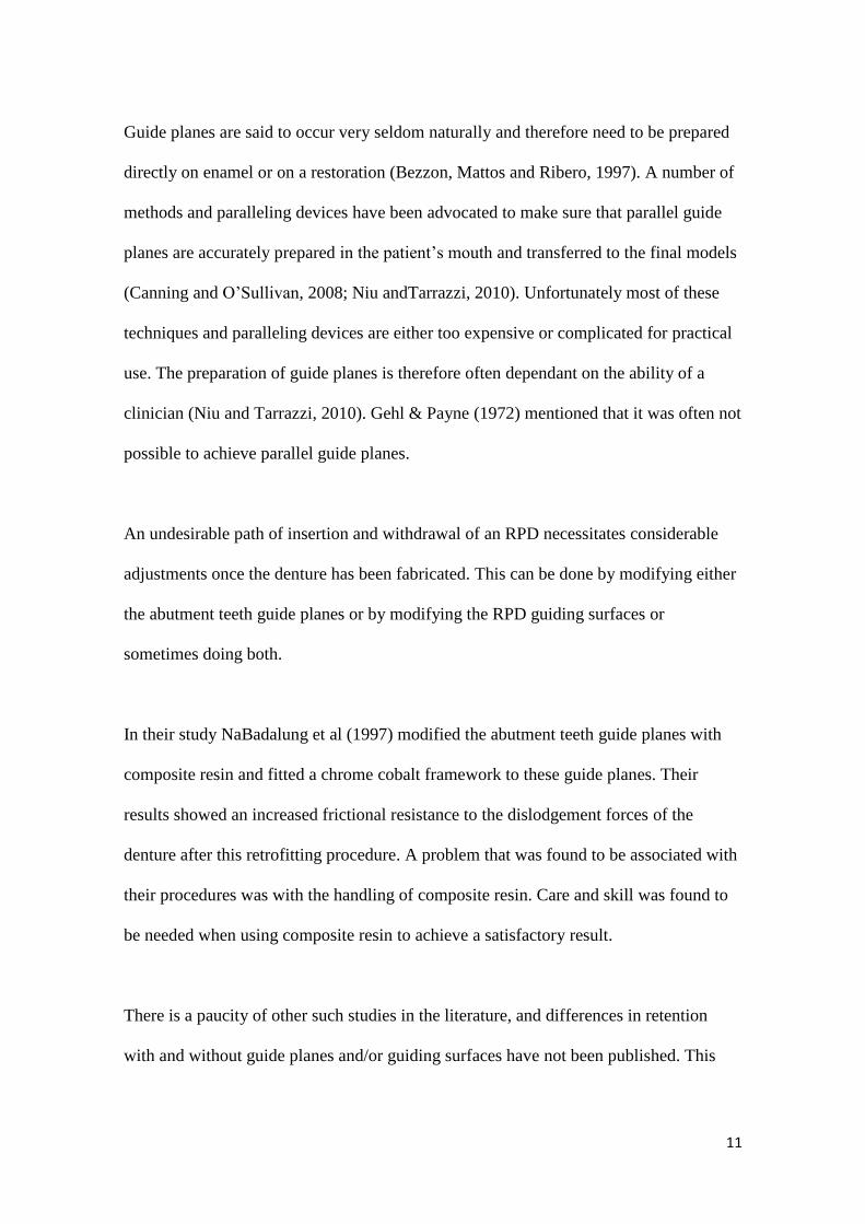
A custom built platform and jig was constructed for the tensile testing machine used
(Instron, UK). This platform enabled the placement of the jig so that the hook could be
directly under the upper jig of the machine, and could also be varied at an angle to the
initial path of insertion, which was made perpendicular to the occlusal plane (figures 3-
5).
Figure 2 Acrylic partial denture with hooking device to enable placement in a universal testing machine.
Figure 5 Typodont model on custom-made platform on universal testing machine with hook in place on upper jig.
Figure 3 Side view of lower jig made to take a model platform from a model surveyor.
Figure 4 Calibrated mechanism to provide tilt to vary the path of insertion/withdrawal.
17
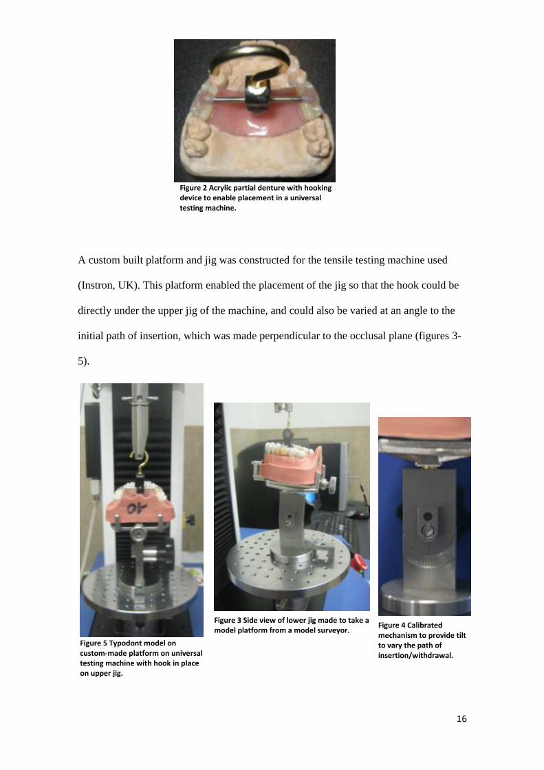
Measurements (of forces for pulling the dentures away from their models) were then
taken at 0, 2, and 5 degrees (10 measurements per angulation) by raising the upper jig at
a cross-head speed of 2 mm per minute, which was considered an appropriate speed to
record the frictional force effects.
This typodont model was then modified by preparing guide planes on the surfaces of the
abutment teeth adjacent to the edentulous space (i.e. distal of 14 and 24 and mesial of
17, 27) using a diamond bur. This was done in the same manner as would be done
clinically, without any paralleling device (figures 6 and 7).
An impression of this model was then made in the same as the first, and again the model
sent to the laboratory for the construction of a second removable partial denture. Both
these dentures were thus made in exactly the same way by the same laboratory, with no
particular instructions given, in order to simulate the clinical situation.
Figure 6 Preparation of guide planes on the typodont model.
Figure 7 Occlusal view of the prepared guide planes.

18
This second partial denture was subjected to exactly the same procedures as the first, by
removing the buccal flanges and placing the hooking device in the same manner.
Another set of measurements were made, again at the three different paths of
insertion/withdrawal.
This second denture was then modified to add guiding surfaces that would match the
guide planes of the typodont teeth. Retention grooves were ground on the guiding
surfaces and autopolymerising acrylic resin (Unifast Trad, GC, USA) was mixed and
placed on these surfaces. The guide planes on the abutment teeth were lubricated with
Vaseline, and when the autopolymerising resin had reached the dough stage, the denture
was placed carefully along the path of insertion and taken in and out of the model until
the exothermic heat of reaction commenced. This procedure simulated the procedure
followed clinically. The denture was placed in hot water (at <70°C) until the acrylic was
set, and excess acrylic was trimmed away.
Measurements were again taken in the universal testing machine as for the previous two
situations.
3.4 Analysis
The results were analysed using appropriate analyses of variance using the Statistical
Package and Service Solutions (SPSS Inc, Chicago, USA).

19
3.5 Study validity and reliability
The model, denture, guide plane and guiding surface placement are imperfect
simulations of the clinical situation. In addition, only variations to the path of insertion
in an antero-posterior direction were measured. Thus there may be weak external
validity. However, if significant differences are observed between the three clinical
situations, the results are valid for the clinical situation as the chewing and displacing
forces in the mouth vary considerably in direction and so the retentive force from guide
plane retention would be expected to be greater.
Reliability was improved by taking each set of measurements ten times and using the
mean for interpreting the results. The laboratory work was performed by the same
person (a senior laboratory technician), in the same dental laboratory (Wits Dental
Hospital laboratory). Also one operator (i.e. the researcher) took all the measurements.
All materials that were used in this study were used according to the recommendation of
the manufacturer. The measuring instrument was calibrated every time a new test was
done.

20
4 Results
The maximum loads (measured in Newtons) were recorded for the 3 sets of dentures at
0, 2 and 5 degrees. The results were recorded as graphs and tables directly from the
software (Bluehill Lite, Instron, UK). An example is given below for the first denture,
and subsequent plots and tables are shown in Appendix 1. The data were then analysed
for statistical comparisons and summarised as below. Full analyses also appear in
Appendix 2. For each denture situation appropriate analyses of variance tests were
carried out, the results of which are given below.
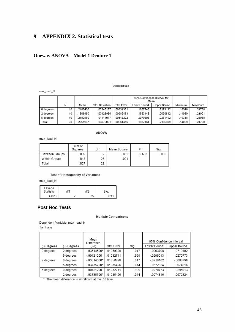
4.1 Model 1, Denture 1: no guide planes or surfaces
4.1.1 Denture at 0°
Figure 8 Load vs extension graph at 0⁰ for denture 1. The graphs were modified by offsetting each subsequent test in order to make the graph more readable.

21
4.1.2 All degrees for Model 1
The means and standard deviations for all the degrees for Model 1 shown in Table 2,
together with the statistical differences derived from the data in Appendix 2.
Table 2. Results for Model 1, denture 1. Figures in red are statistically significant at p<0.05
Denture 1 Mean Max
Load (N) Standard Deviation
ANOVA test result on mean differences
2⁰ 5⁰
0⁰ 0.217 0.029 0.047 0.999
2⁰ 0.181 0.031 0.014
5⁰ 0.205 0.014
The retentive force dropped significantly when the model was tilted at 2⁰ but was
regained at 5⁰.
Table 1. Loads at 0⁰ for denture 1
Table 1. Loads at 0⁰ for denture 1

22
4.2 Model 2, Denture 2: guide planes on the teeth, no guiding surfaces on the
denture
The results for these tests are again summarised from the data in Table 3.
Table 3. Results for Model 2, denture 2. Figures in red are statistically significant at p<0.05
Denture 1 Mean Max
Load (N) Standard Deviation
ANOVA test result on mean differences
2⁰ 5⁰
0⁰ 0.352 0.045 0.072 0.007
2⁰ 0.315 0.032 0.554
5⁰ 0..308 0.030
There was a decreasing retentive force with increasing angle of deviation from the path
of insertion/withdrawal.
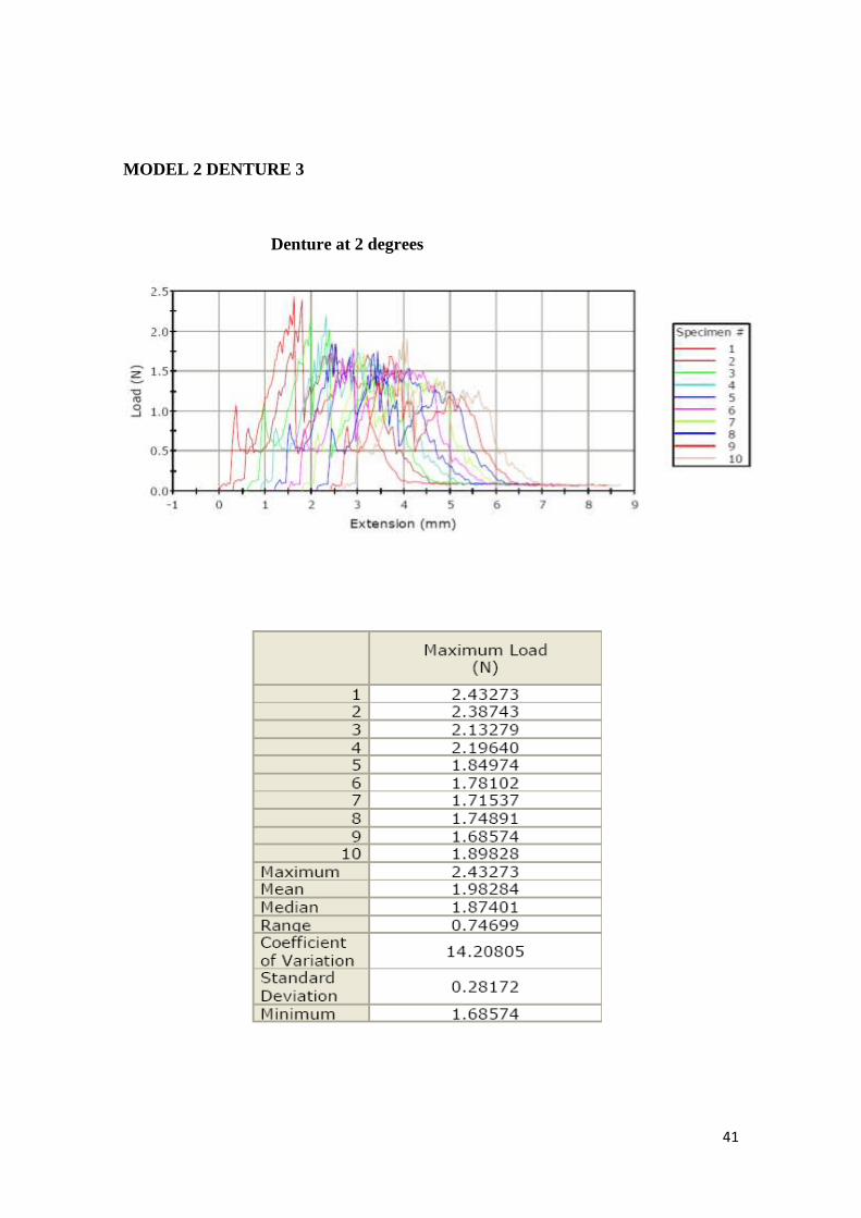
4.3 Model 2, Denture 3: guide planes on the teeth, and guiding surfaces on the
denture
The results for these tests are again summarised from the data in Table 4.
Table 4. Results for Model 2, denture 3. Figures in red are statistically significant at p<0.05
Denture 1 Mean Max
Load (N) Standard Deviation
ANOVA test result on mean differences
2⁰ 5⁰
0⁰ 2.681 0.162 0.000 0.015
2⁰ 1.983 0.282 0.001
5⁰ 2.463 0.199
There was a significant drop in retentive force at 2⁰, regained to some extent at 5⁰ but
this remained significantly different from 0⁰.

23
4.4 Comparisons between all the dentures
The results for comparisons of the means for all dentures using the path of insertion (i.e.
at 0⁰) are summarised in Table 5. Denture 1 had no guiding surfaces and the teeth had
no guide planes. Denture 2 had no guiding surfaces but the teeth had guide planes.
Denture 3 had guiding surfaces and the teeth had guide planes.
Table 5. Results for all dentures at 0⁰. Figures in red are statistically significant at p<0.05
Mean Max
Load (N) Standard Deviation
ANOVA test result on mean differences
Denture 2 Denture 3
Denture 1 0.217 0.030 0.000 0.000
Denture 2 0.352 0.045 0.000
Denture 3 2.681 0.162
There was a statistically significant difference between all dentures, thus rejecting the
null hypothesis. There was a significant increase in retentive force of 1.6 times from
denture 1 to denture 2, of 7.6 times from denture 2 to denture 3, and 12.3 times from
denture 1 to denture 5, as depicted in figure 9.
0
0.5
1
1.5
2
2.5
3
Denture 1 Denture 2 Denture 3
Mean Max Load (N)
Fig. 9 Mean maximum loads of dentures at 0⁰

24
5 Discussion
Despite new and sophisticated methods of constructing RPDs such as the use of three-
dimensional computer aided design or computer assisted manufacturing (Han and
Wang, 2010), conventional acrylic RPDs are still the most widely used RPDs
(MacEntee, 2011). Acrylic RPDs can be strong, are easily repaired and adjusted and
comparatively easy to fabricate, certainly when compared with metal based RPDs. They
are also relatively cost-effective and are prescribed for those patients who cannot afford
other treatment options: in other words the majority of patients.
Our clinical experience has been that acrylic-based RPDs with tooth support can be
regarded as permanent prostheses and are ideal not only because they are cost-effective
but also because if they can be made retentive enough through the use of guide plane
retention there may be no need for clasp arms. This would make them also ideal for the
elderly, and institutionalised patients who find it difficult to manipulate a denture with
clasps and who may rely on care-givers who may not take sufficient care with clasps.
Consequently many of these are lost or bent and the denture becomes unserviceable.
This study therefore set out to ascertain whether our experience of trying to improve
guide plane retention by refining guiding surfaces in the mouth, had any validity. The
results clearly show this to be the case, but there are some interesting observations to be
made. From clinical observation the denture is considered to be more retentive when the
path of insertion is at a slight angle. The expectation in this case was therefore to
observe significant differences between the 0⁰ and the 2⁰ and 5⁰ with 0⁰ being the least

25
retentive. But in this case the 2⁰ seemed to have a decreased frictional force and the 5⁰
almost the same as the 0⁰.
There are two possible explanations for this. First, considering the denture 1 (without
guiding surfaces or guide planes), it is logical that the „fit‟ of the denture against the
teeth would be best when in its position at rest. However, there could only be points of
contact between the resin and the teeth, most of which will be recruited when the
denture is moved along its path of withdrawal. However, when tilted at 2⁰, many of
these points will initially be lost, and so the retentive force will be less. At 5⁰ on the
other hand, there will be greater „binding‟ of the denture against the teeth, and the
retentive force is likely to increase. These were precisely the observations in this study
(Table 2).
With respect to the second denture (without guiding surfaces but with guide planes), the
same situation is likely to occur, but this time the retentive force should be greater as
more of the denture is likely to contact the now prepared guide planes on the teeth.
However, the quality of the contact may still not be that improved, because of the
inherent inaccuracies in the processing of an acrylic base and the need for the technician
to block out undercuts. Hence it was not surprising that once again there was a decrease
in retentive force at 2⁰, but there was a further slight but not significant decrease at
5⁰ (Table 3).
Logically, therefore, with denture 3 there should be no such drop in retention at 2⁰
because now there is intimate contact between the guide planes on the teeth, and the

26
guiding surfaces on the denture. However, once again, a drop in retentive force was
observed at 2⁰ (Table 4). There is a possible explanation for this, which lies in the
nature of the model used. This is a typodont model, where the teeth are held in the
model by means of retentive elements and undercuts: they „click‟ into place. But they
are also not rigid, and are capable of movement. The superior contact of the denture
guiding surfaces with the tooth guide planes is evidenced by the greatly increased
retentive force at 0⁰. But it is possible that this improved contact will cause binding
against the teeth when at an angle to the path of withdrawal. This should produce a
higher retentive force, but it may also be great enough to move the teeth slightly first
during withdrawal at an angle, and this could explain the drop in retentive force at 2⁰.
At 5⁰ the force exerted on the teeth will be greater and exceed their movement and
therefore it is logical that the retentive force would again increase.
Observations have been made that most of the time RPDs still fit poorly despite the care
that is taken to fabricate them (Stern et al, 1985; Brudvik & Reimers, 1992). Both
laboratory and clinical procedures have an impact on this outcome. The preparation of
guide planes on the abutment teeth of RPDs is one of the important principles of
constructing RPDs. RPD retention has been reported to increase when guide planes are
prepared on abutment teeth. Steward, Rudd and Kuebker (1993) recommended that as
many guide planes as possible must be prepared on the abutment teeth.
The results obtained from this study show an increase in retention when guide planes
are prepared on the teeth; but more than that, when the guiding surfaces were
specifically shaped to those guide planes after processing of the denture, retention was

27
almost doubled. The outcome of this study is very encouraging. It highlights how a
quick and easy procedure such as modifying the guiding surfaces can make a large
difference to the fit of an RPD. It allows for more applications of claspless dentures (but
which should always have tooth support) for dentures in the aesthetic zone; for patients
with less dexterity such as those with rheumatoid arthritis and the elderly; for improved
ease of maintenance; and for reducing the financial burden on patients and the health
sector.
Problems associated with the use of removable partial dentures include development of
caries on abutment teeth, mobility of abutment teeth, and continuation of periodontal
breakdown. All of these are linked to poor oral hygiene and so regular maintenance and
oral hygiene care must be carried out (Akaltan and Kaynak, 2005). It may be somewhat
cynical to mention that the advantage of modifying guiding surfaces with
autopolymerising acrylic is that the acrylic will deteriorate over a certain period of time
and may result in a slight loss of retention. This will call for another modification of the
guiding surfaces and may hopefully encourage the patient to return for this, at which
stage the abutment teeth and oral hygiene may be assessed and managed accordingly.
The preparation of guide planes might also pose a challenge/problems to both the
clinician and the patient. After tooth loss, teeth adjacent to edentulous spaces tend to tilt,
drift or over-erupt into the edentulous space (Owen, 2000). Guide plane preparation to
these teeth might be difficult if not impossible without mutilating the teeth. Sometimes
preparation of the guide plane might cause sensitivity to the teeth especially if the
preparation was not confined to the enamel only (i.e. dentine exposure). Krikos (1975)

28
advised that the guide plane preparation be polished and protected by an application of
fluoride.
This study has given insight into how oral rehabilitation with acrylic RPDs can be
improved without any complicated procedures at comparatively little cost. This
improvement will lead to more predictable results with RPDs and the possibility of
more individuals being able to wear their RPDs. In some earlier studies cited in van der
Bilt et al (1994), improved masticatory performance was observed after treatment with
removable partial dentures. Van der Bilt et al (1994) found the objective masticatory
function and average masticatory performance to increase in partially dentate patients
who were given RPDs. This outcome of RPDs is very important especially for frail
elderly patients.
Limitations and opportunities
The limitations of this study are that it is an in vitro simulation of clinical situations and
that the „teeth‟ were typodont resin-based teeth and are softer than enamel. Furthermore,
they are not firm in their sockets. The study could be repeated with a better simulation
of the clinical situation, perhaps with extracted teeth embedded in an artificial
periodontium. It would also be useful to know just where the contacts between the
denture and the teeth occur.
Despite the limitations, the stark differences between the three clinical situations are
considered sufficient to confirm the clinical anecdotal evidence of much improved
retention when guiding surfaces are adapted clinically to guide planes.

29
This study has also highlighted a number of opportunities for other studies. The study
was done using a bounded saddle and therefore other types of RPD Kennedy
classification such as class I and II could be investigated in the future. The influence of
guide plane and guiding surfaces when used in combination with clasp should also be
investigated.
30
6 Conclusions
The main objective of this study was to measure the influence of abutment teeth guide
planes and partial denture guiding surfaces on removable partial denture retention, one
of the important elements of RPD success. The outcome of the study showed that guide
planes increase the retention of the RPD, but that when guiding surfaces are adapted
closely to the guide planes, retention was observed to increase even more. Guide plane
retention has been reported in the past but the effect of guiding surface modification has
not been reported at all in the literature, especially using a simplified and cost-effective
method that was used in this study.

31
7 References
Akaltan F, Kaynak D. An evaluation of the effects of two distal extension removable
partial denture designs on tooth stabilization and periodontal health. J Oral Rehabil.
2005;32:823-829.
Bezzon OL, Mattos MGC, Ribero RF. Surveying removable partial dentures: the
importance of guiding planes and path of insertion for stability. J Prosthet Dent 1997,
78:412- 18.
Brudvik JS, Reimers D. The tooth-removable partial denture interface. J Prosthet Dent
1992; 68:924- 927.
Canning T, O‟Sullivan M. Acrylic resin jigs as an aid to parallel guiding plane
preparation. J Prosthet Dent 2008; 99:162-164.
Frank RP, Brudvik JS, Leroux B, Milgrom P, Hawakins N. Relationship between
standards of removable partial denture construction, clinical acceptability, and patient
satisfaction. J Prosthet Dent 2000; 83:521- 527.
GPT 8. The glossary of prosthodontic terms. J Prosthet Dent. 2005; 94:10-92.
Gehl DH, Payne H. Achieving planned parallel guiding planes for removable partial
dentures. J Prosthet Dent, 1972; 27:654- 661.

32
Han J, Wang Y. A preliminary report on designing Removable Partial Denture
framework using a specifically developed software package. Int J Prosthodont, 2010;
23:370- 375.
Krikos AL. Preparing guide planes for removable partial dentures. J Prosthet Dent
1975;34(2): 152- 155.
MacEntee MI. Oral Healthcare and the Frail Elder. A clinical Perspective. Blackwell
Publishing Ltd. First edition. 2011. Pg 224.
Marcus PA, Joshi BD, Jones JA, et al. Complete edentulism and denture use for elders
in New England. J Prosthet Dent 1996; 76:260-266.
NaBadalung DP, Nichols JI, Brudvick JS. Frictional resistance of removable partial
dentures with retrofitted resin composite guide planes. Int J Prosthodont 1997; 10:116-
122. `
Niu E, Tarrazzi D. Use of a silicone transfer index to prepare parallel guide planes. J
Prosthet Dent 2010; 104:347-348.
Owen CP. Fundamentals of removable partial dentures .University of Cape Town Press.
Second edition. 2000. Pg3- 7.
33
Stern MA, Brudvik JS, Frank RP. Clinical evaluation of removable partial denture rest
seat adaptation. Journal of Prosthet Dent 1985; 53:658- 662.
Steward KL, Rudd KD, Kuebker WA. Clinical removable partial prosthodontics. 2nd
ed.
Ishiyaku EuroAmerica, Inc.publishers. Tokyo 1992. Pg 104.
van der Bilt A, Olthoff LW, Bosman F, Oosterhaven SP. Chewing performance before
and after rehabilitation of postcanine teeth in man. J Dent Res 1994; 73:1677- 1683.
Zwetchkembaum SR, Shay K. Prosthodontic considerations for the older patient. Dent
Clinics North America 1997; 41:817- 842.

34
8 APPENDIX 1. Graphs and tables from the tensile testing machine
MODEL 1 DENTURE 1
Denture at 0 degrees

35
MODEL 1 DENTURE 1
Denture at 2 degrees

36
MODEL 1 DENTURE 1
Denture at 5 degrees

37
MODEL 2 DENTURE 2
Denture at 0 degrees

38
MODEL 2 DENTURE 2
Denture at 2 degrees

39
MODEL 2 DENTURE 2
Denture at 5 degrees

40
MODEL 2 DENTURE 3
Denture at 0 degrees
41
MODEL 2 DENTURE 3
Denture at 2 degrees

42
MODEL 2 DENTURE 3
Denture at 5 degrees
43
9 APPENDIX 2. Statistical tests
Oneway ANOVA – Model 1 Denture 1

44
Oneway ANOVA – Model 2 Denture 2

45
Oneway ANOVA – Model 2 Denture 3

46
Oneway ANOVA – All models/Dentures at 0 degrees