guide to electronic system development
TRANSCRIPT

#ONLYFORWARD
GUIDE TO ELECTRONIC SYSTEM DEVELOPMENT

#ONLYFORWARD
2 /
ALT
AIR
INTRODUCTIONManufacturers today are tasked with designing smart, connected products at a breakneck pace to stay ahead of the competition. As performance demands continually increase, packaging sizes become smaller, and device connectivity becomes more critical, schematic engineers and product designers need ways to make efficient design decisions and collaborate with one another to optimize complex interconnected mechanical and electromagnetic systems. To develop the next generation of smart products, organizations are turning simulation to improve device performance and drive profitability.

#ONLYFORWARD
3 /
ALT
AIR Electronic System Development Guide
Electronics are a part of our lives – both professionally and personally – with the latest
gadgets delivering an immediate gateway to the world. Innovation, time to market
and lower cost are the keys to electronics success, and the pressures to quickly deliver
innovative products at lower cost is intense. This guide demonstrates the use of
simulation-driven design to accelerate smart, efficient electronics product development.
Electronic System Development Guide
04 / What is a Smart Product?
05 / IoT Hierarchy of Needs
07 / Electronic Design
12 / Simulating Sensors and Actuators
16 / Embedded Code Development
19 / Mechanical and Thermal Performance
27 / Antennas and On-device Connectivity
33 / Working with Altair

#ONLYFORWARD
4 /
ALT
AIR WHAT IS A
SMART PRODUCT?A smart product has built-in intelligence to read, adapt, and react to the operating
environment in which it is used. Smart products have sensors to perceive their
surroundings, and electronics, embedded code, and on-board systems to decipher
the incoming signal from the sensors. Depending on the system design logic, sensor
data is then stored locally or transmitted to and from the cloud. Finally, algorithms
found either locally or on the cloud utilize this data to arrive at the appropriate action
and trigger the actuators which execute the action.

#ONLYFORWARD
5 /
ALT
AIR IOT HIERARCHY OF NEEDS
This guide provides an overview of the electronic system development process for smart
connected devices.
If you want to learn how to design an IoT strategy and effectively connect your smart
devices at scale Read the Guide to Smart Product Development.
Apps
IoT
Device Management
Antennas
Connectivity
Electronic Design & Embedded Code
Sensors & Actuators
Mechanical & Thermal Performance
Gateway
Firmware
Firmware
Hardware
Hardware

#ONLYFORWARD
6 /
ALT
AIR
“Smart, connected products require a fundamental rethinking of design. At the most basic level, product development shifts from largely mechanical engineering to true interdisciplinary systems engineering.”Porter, Michael, Heppelmann, James (2015), “How Smart, Connected Products Are Transforming Companies”, Harvard Business Review October 2015, Harvard Business Publishing, Accessed 17 November 2020

#ONLYFORWARD
7 /
ALT
AIR ELECTRONIC DESIGN
Delivering electronics that delight consumers requires more than just linking the ECAD
and MCAD worlds, it requires physics analysis at the speed of design and collaboration
across disciplines throughout development. Altair PollEx™ brings Altair’s simulation-
driven design philosophy to the electronics industry, inspiring innovation while ensuring
timing, performance, reliability, and compliance targets are met.
Designing consumer electronics for mass production requires a team of experts focusing
on various aspects of design and manufacturing process. With a fragmented engineering
process, exchange of models and information can cost valuable time in a competitive
landscape. Central to a successful design collaboration process is an agile toolset used
within the component, subsystem, and system-level design as well as across logical and
physical design spaces.
PollEx offers a unified part library for physical, logical, thermal, electrical, and assembly
attribute data so teams can seamlessly share data and modify designs at any stage
of the development cycle. PollEx also integrates with all major ECAD and simulation
tools, increasing efficiency and performance while fitting into existing tool chains with
unsurpassed connectivity.
Concept
Schematic Design
• Component Selection• Circuit Design• Electrical Rule Checking• Functional Simulation• BOM• Netlist
• Land Pattern• Board Outline/Mechanical• Placement• Layout Guidelines• DRC• Route• Clean-up• Gerber
• DRC• SI/PI• EMI/EMC• Thermal• Structural• Manufacturing• Assembly• Review
PCB Design
Design Review
Fabrication
Assembly
Testing
Concept Specifications

#ONLYFORWARD
8 /
ALT
AIR Concept Design
The first step in an electronics design process is to visualize and review the initial concept
design. Using PCB design software at an early stage allows designers to detect design
faults and avoid costly downstream issues.
PollEx is the most comprehensive and integrated set of PCB design viewing, analysis,
and verification tools for electrical, electronics, and manufacturing engineers. PollEx
transfers data flawlessly between the industry’s most popular ECAD and simulation tools
and enables many of the world’s major electronics corporations to quickly visualize and
review PCB designs. Its checking tools detect issues early in the design to avoid product
failures and simplify manufacture and assembly.
Schematic DesignSimulation enables schematic engineers to make better product design decisions earlier
in the design process and PCB schematic data allows for optimization of the underlying
programming logic. Early checks can be performed for signal integrity, power integrity,
electromagnetic interference (EMI) vulnerability, and electrostatic discharge (ESD)
protection, ensuring return path routing, balanced differential pairs, and verifying many
other essential features.
PollEx offers users a schematic design viewer which reads in the design data from various
schematic design tools. It shows schematic objects, logic symbols, net connections, and
other related objects in individual design sheets. By combining objects, users can easily
identify the location in the sheet and attributes of the object. Bill of materials (BOM) files
can also be extracted from the schematic design data.
PollEx validates BOM, logical system design and PCB schematic data to ensure error-
free translation and facilitate the comparison of PCB and schematic revisions using the
industry’s best ECAD connectivity. Using your own ECAD tool, you can perform logical
design verification and ensure proper schematic behavior.

#ONLYFORWARD
9 /
ALT
AIR
“Having [electronic sensor simulation, SPICE simulation, and data processing] together allows Schneider Electric to use a global approach to optimizing our solutions.”Bertrand Du Peloux, Schneider Electric
Schneider Electric uses Altair simulation tools to design reliable and versatile sensors which treat data for various smart system tasks like remote monitoring and actuation of circuit breakers.

#ONLYFORWARD
10 /
ALT
AIR PCB Hardware Design
The most important part of any electronic device is the PCB, which hosts all of the
product’s functional modules. The typical workflow involves multiple iterative design
cycles, but PCB visualization and review tools help address design issues and shorten
overall process time.
Typical Workflow of a PCB Design
Ideas
Schematic Netlist PCB
BOMGerber Review
Production
ControlIC
BT IC &Antenna
MemoryIC
LCDDriver IC
AudioAMP
Charging IC
SPKOut
Functions Choose Components
Virtual Prototype
The PollEx design for electrical engineering tool detects electrical issues via verification
earlier during the design phase. Pollex provides early checks for signal integrity, power
integrity, electromagnetic compatibility, and interference vulnerability (EMC/EMI) and
ESD protection, ensuring return path routing, balanced differential pairs, and verifying
many other essential features.
In the case of a wireless smart speaker, PCB design considerations might include different
audio lines, sheilding from audio lines, and thermal behavior of the main ICs, all of which
effect the audio quality. Design for electrical and thermal analysis tools can be used to
model and optimize the performance of these key factors.
Additionally, satisfaction of specific impedance and safe use of high-speed bus lines are
critical for the high-speed performance of the speaker. Signal integrety analysis is ideal
for ensuring the PCB meets the desired performance targets.

#ONLYFORWARD
11 /
ALT
AIR Design Review
Schematic design review is a critical step in the design process of electronics. A challenge
of the design review stage is managing multiple EDA vendors and ECAD formats that
are typically used at various stages of the design process. Pollex interfaces with all major
EDA vendors, making it an easy to use software to collect disparate design elements for
global review.
Comparison between PCB-to-PCB and schematic-to-schematic designs are executed
in this stage, as well as comparisons across PCB, schematic design, and BOM. Design
reviewers query, search, and measure artwork, physical, and composition layer views
for PCB objects. Pollex users also have access to part, net, pad stack, and via libraries.
Design reviewers can also view the net 2D and 3D display, net topology display, and
perform automatic composite net generation and can red-mark features for comment.
Signal integrity, power integrity, and thermalPollEx signal integrity and power integrity solvers provides early checks for signal
integrity and power integrity, ensuring return path routing, balanced differential pairs,
and verifying many other essential features.
PollEx investigate signal integrity and thermal PCB problems thanks to intuitive and
easy to use solvers for board-level analysis. Included are efficient domain signal integrity
solvers with SPICE and IBIS model support for wave propagation delay, reflection,
crosstalk, eye diagrams, scattering, admittance, and impedance matrix calculations.

#ONLYFORWARD
12 /
ALT
AIR SIMULATING SENSORS
AND ACTUATORSSmart sensors and actuators are strategic components for smart product monitoring
and control. No matter whether data is processed at the device level or in the cloud,
sensors and actuators have to be accurate, reactive, and energy efficient in order to
deliver the performance needed for smart systems.
On top of performance optimization, sensors and actuators also provide challenges
for architecture integration. They often need to be miniaturized, and when possible,
integrated into the PCB without sacrificing reliability or adding to manufacturing costs.
Sensor-PCB integration can be a source of electromagnetic interference, and sensor and
actuators will also generate heat. The presence of steel, magnets, and copper will impact
product weight and its distribution within the device, which needs to be considered in the
simulation of mechanical and thermal performance.
Using electromagnetic simulation technology, device designers can prioritize these key
attributes and design, simulate, and optimize the performance of sensor electronics or
permanent magnets. EM results can even be used within Design of Experiments (DoE)
software for performance optimization.
Altair’s low-frequency electromagnetic analysis software helps engineers design more
compact, more efficient, and more accurate actuators. This tool also makes it possible
to perform accurate virtual prototyping of magnetic sensors thanks to advanced
modeling techniques considering material non-linearities, eddy currents, circuit coupling
and motion with mechanical loads.
Miniaturization, efficiency, weight, high level of controllability and cost are key criteria to optimize for linear actuators and motors.
A complete study of sensor behavior (electromagnetic, mechanical, and electrical) can
also be achieved through simulation. Electromagnetic analysis is carried out to record
flux density, currents, losses, current density. On the mechanical side position, speed,
force, and torque can also be studied. For electrical sensor performance, Altair’s software
offers quantities for current, voltage, inductance, and resistance.

#ONLYFORWARD
13 /
ALT
AIR
Altair tools enable the design of compact, cost effective, and easily integrated position and speed sensors.
Altair’s Model-based development (MBD) tools can help drive faster assessment of
system performance by enabling the flexible configuration of sensor systems and
simulating the sub-systems and control strategies for each function of the device.
Simulating complex products as systems-of-systems allows smart product designers
to explore how sensor resolution, accuracy, and precision, as well as the thermal,
mechanical, electronic, and electromagnetic output of actuators, may influence the
performance of the system as a whole. MBD enables easier integration into a global
system and helps to improve energy management by identifying potential energy
flow issues and various types of energy loss.
Finally, with advanced functions such as Altair’s SPICE simulation technologies, users can
consider signal processing and data analysis from the concept level to avoid data noise
and treat unnecessarily large data sets prior to transmission.

#ONLYFORWARD
14 /
ALT
AIR
The simulation-driven design of this medical auto-injector involved modeling of actuators and sensors executing the injector’s functions.
Learn More About Electromagnetic, Electric, and Thermal Analysis

#ONLYFORWARD
15 /
ALT
AIR
Motorola Mobility Simulates Actuators and Camera System to Ensure Optimal DesignSmartphone cameras use voice coil motor (VCM) actuators to translate a lens in three
degrees of freedom in order to bring an object to focus on the image plane and to
optically stabilize the camera. To ensure optimal design, the Motorola Mobility team
used Altair electromagnetic analysis tools to simulate the entire VCM and camera
system. This allowed the team to quickly validate designs and ensure that the part
compatibility and camera performance met the design targets.
Other devices within the phone, such as speakers, antenna shields, accessory
magnets etc. can affect the VCM performance due to magnetic interference.
With EM simulation, the team simulated the entire VCM and phone layout,
accounting for all possible magnetic interference from other devices.
With Altair EM software, the team simulated the entire VCM and phone layout,
accounting for all possible magnetic interference from other devices. Full simulation
of a VCM system is a requirement for any new or high-risk design. These simulations
take place during part selection and product design phases in order to proactively
rule out any issues that may arise.
View the Motorola Customer Story
This simulation shortened design cycles giving the team
access to quick and reliable answers. This cut the design
time from weeks and months, to days and hours, allowing
the Motorola Mobility team to remain agile and quickly
iterate on designs. The team can easily check design
integrity and detect issues that otherwise would not
be found until parts are tooled, which is too late in the
development cycle.
Example simulation of the Motorola One Zoom

#ONLYFORWARD
16 /
ALT
AIR EMBEDDED CODE
DEVELOPMENT Firmware Development with Embedded System DesignVisual environment software is essential to the smart product development process,
allowing users to avoid the tedious and sometimes error-prone process of manually
writing code for embedded systems. Instead, software can automatically generate code
directly from your system diagram.
To develop complex embedded systems like sensor and actuator controls, vision
systems, and IoT devices, you need software for model-based firmware development.
Altair’s tools let you design, analyze, and simulate your embedded system using
block diagrams and state charts, then automatically generate compact and optimized
code to run on an extensive selection of microcontrollers from Texas Instruments™,
STMicroelectronics®, Arduino®, Raspberry Pi™, and others. Hardware-in-the-Loop testing
is fully supported using a high-speed bidirectional communication link for data collection
and real-time tuning.
Learn more about Embedded System Development

#ONLYFORWARD
17 /
ALT
AIR
PaceControls Uses MBD to Eliminate HVACR Control System DefectsPaceControls, a leading technology developer and manufacturer of cloud-based
Internet of Things (IoT) solutions for the HVACR industry, took a model-based design
approach for their next-generation HVACR equipment control. By leveraging Altair’s
embedded system design software, they deploy over 19,000 smart-grid installations
without a single significant reported defect.
The PaceControls technology resides between the thermostat and the HVACR
equipment, accepting the thermostat control signal and other signals to produce
optimized control signals that minimize energy usage of the HVACR equipment.
Additionally, real-time estimates of energy savings are calculated and communicated
to the cloud and customers.
View the PaceControls Customer Story
Altair provided the tools to support an end-to-end model-based design framework
consisting of simulation and Hardware in the Loop (HIL) testing. During the simulation
step, the system requirements are represented by design models, which are dynamic
block diagram and/or state machine models that display the requirement and the
acceptable deviation as a time history signal with maximum and minimum boundary
signals. Design models are linked to their requirements and embedded in the models.
Next, dynamic models of the HVACR systems are created followed by the design,
analysis, and modeling of the energy and demand optimization control algorithms.
The combined “controls + plant” model goes through an iterative “analysis + redesign
+ simulation” process until its performance lies within the acceptable range for each
of the design models. Embed block diagrams and state charts, the analysis toolbox,
filtering, and optimization functions are used extensively during the simulation step.

#ONLYFORWARD
18 /
ALT
AIR During the HIL testing step, Altair firmware tools automatically generate C code for
the controller model. The code is then compiled with support libraries as an Android
application where it executes on the PACE Node utilizing a cloud-connected Qualcomm
Snapdragon microcontroller. The product is then tested in a desktop setting to ensure
sensor scaling, latency, order of execution, initialization, CPU utilization, and accuracy
are being calculated correctly. In the desktop setting the plant is replaced by a general
purpose I/O board controlled by a design model producing test signals for sensors and
recording actuator signals from the microcontroller. Once desktop testing is complete,
the PACE Node system is connected to an actual HVACR system and performance is
re-evaluated subject to the design models.
For PaceControls, Altair’s embedded system design tools fully support the key elements
of their MBD process including requirement capture, control system analysis and design,
filtering, optimization, simulation testing, automatic code generation, and HIL testing.

#ONLYFORWARD
19 /
ALT
AIR MECHANICAL AND THERMAL
PERFORMANCEStructural Analysis in the Early Design StageRapid design iteration is key to early stage evaluation of a design’s feasibility.
Consumer electronics need to withstand abusive loads both during use as well as
during storage, shipping, and in the retail setting. Solving structural load cases on PCBs,
however, can be a time consuming in traditional CAE tools due to the pre-processing
requirements on these intricate geometries.
The structural analysis solver available within the Altair Inspire™ design, analysis,
and optimization suite offers a way for designers to get structural analysis insights
on complex assemblies in seconds or minutes without CAD geometry cleanup or
meshing and assembly work. On the game controller below, multiple design variants
of this 250-part assembly were imported and analyzed in seconds to compare structural
and thermal deformations.
Structural analysis of a gaming controller and its PCB using SimSolid
requires no meshing or geometry modification.
#ONLYFORWARD
20 /
ALT
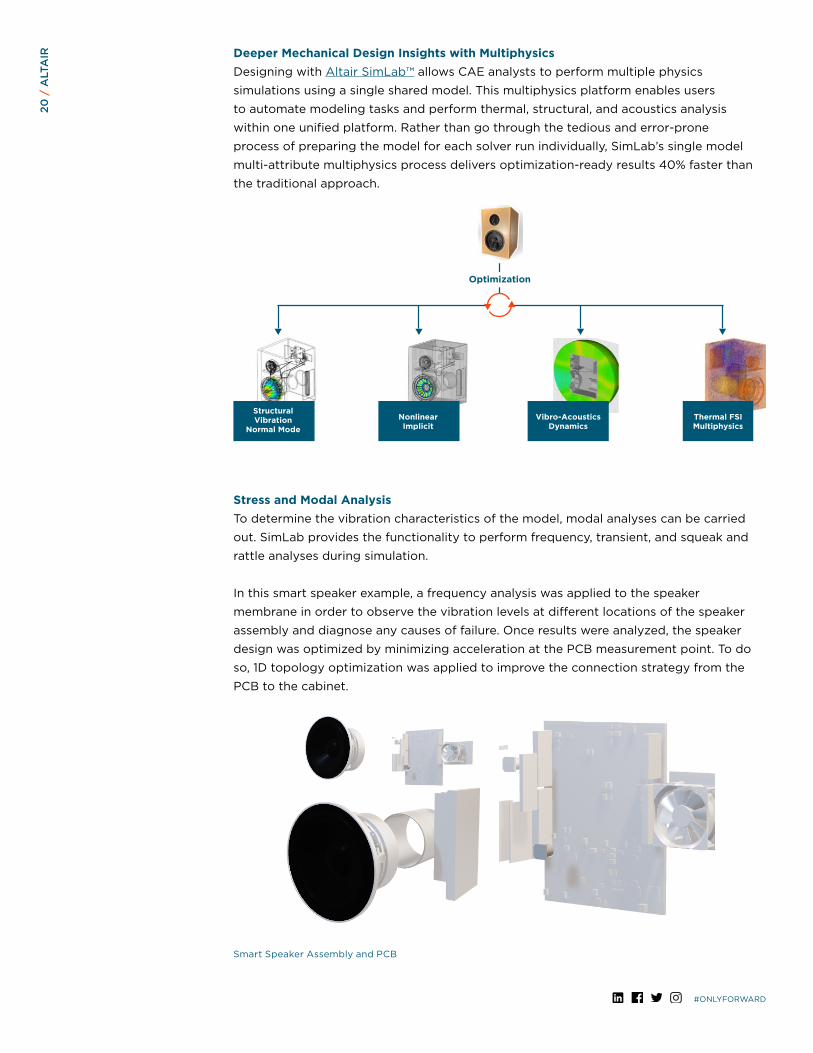
AIR Deeper Mechanical Design Insights with Multiphysics
Designing with Altair SimLab™ allows CAE analysts to perform multiple physics
simulations using a single shared model. This multiphysics platform enables users
to automate modeling tasks and perform thermal, structural, and acoustics analysis
within one unified platform. Rather than go through the tedious and error-prone
process of preparing the model for each solver run individually, SimLab’s single model
multi-attribute multiphysics process delivers optimization-ready results 40% faster than
the traditional approach.
Stress and Modal AnalysisTo determine the vibration characteristics of the model, modal analyses can be carried
out. SimLab provides the functionality to perform frequency, transient, and squeak and
rattle analyses during simulation.
In this smart speaker example, a frequency analysis was applied to the speaker
membrane in order to observe the vibration levels at different locations of the speaker
assembly and diagnose any causes of failure. Once results were analyzed, the speaker
design was optimized by minimizing acceleration at the PCB measurement point. To do
so, 1D topology optimization was applied to improve the connection strategy from the
PCB to the cabinet.
Smart Speaker Assembly and PCB
Optimization
Structural Vibration
Normal ModeNonlinear Implicit
Vibro-AcousticsDynamics
Thermal FSIMultiphysics

#ONLYFORWARD
21 /
ALT
AIR In addition to speaker aesthetics, sound quality and noise reduction performance are
key drivers of the end-product’s perceived value and price point. Vibro-acoustic analysis
is necessary for understanding what the final product is going to ultimately sound like.
SimLab was utilized to test the speaker for rattling and sound pressure levels, then to
correct any errors that were found in the overall design.
Vibration Testing for noise, vibration, and harshness issues during smart product development
is a critical step in ensuring that a speaker model will satisfy pre-determined quality
targets. By simulating for vibration, product designers can identify causes of unwanted
noise caused by vibration and redesign to dampen or eliminate it before the physical
testing phase. Vibration also creates heat; a major concern when it comes to sensitive
electronics. Full frequency, multiphysics, and acoustic simulation can be performed in
SimLab for users to successfully assess and update their designs.
Acoustic Simulation of a Smart Speaker
Acoustic AnalysisSpeaker + Rattle Loads
Contact ForcesExtraction
RattleAnalysis

#ONLYFORWARD
22 /
ALT
AIR Drop and Abusive Loads
Impact analysis or drop testing is one of the most important stages of product design
and development, and software that can simulate this testing accurately yields dramatic
cost and time-to-market benefits for manufacturers.
It is the job of the manufacturer to design and develop products that perform as well as
possible when dropped, crushed, or otherwise placed in danger of permanent damage.
Drop test simulation software helps manufacturers by speeding up the time to test a
product, enabling higher levels of design quality and reducing the need for physical
testing. Structural analysis tools can replicate the complexity of the physical environment
and materials, simulates the impact or drop event, and provides detailed technical
information about how the product performs during this event. Altair’s structural analysis
software provides a rapidly expanding and efficient set of nonlinear analysis features for
drop test simulation, large displacement testing, preload temperature testing, contacts,
and non-linear material analysis.
LG Electronics Performs Drop Test Simulation on a Smartphone Design

#ONLYFORWARD
23 /
ALT
AIR Thermal
Many factors are considered during a thermal analysis for electronics, from
Computational Fluid Dynamics (CFD) to the elimination of thermal effects of the PCB.
Thermal flow analysis can be conducted on the design of a smart products to test fluid
materials, heat load, inlet flow, fan cooling effects, and other key contributing variables.
For analyst-level users investigating challenging electronics cooling and design
applications, Altair offers thermal analysis solutions that are accessible directly within
its multiphysics environment. This CFD-based tool is capable of solving problems
involving conduction, natural and forced convection, radiation, and conjugate heat
transfer, yet it is easy enough to use for a non-CFD expert. This functionality is also
available within the Altair Inspire platform for early-stage design feasibility studies.
Thermal analysis studies can be carried out at every level of the electronics design.
Altair’s tools can simulate the thermal behavior of the semiconductor and PCB level
to the assembly, wiring and module levels, all the way to the full system-level operation.
This software is especially adept at handling applications such as electronic enclosure
systems, forced cooling systems, busbar systems with circuits, and PCB cooling.
Learn More About Thermal/ElectricalAnalysis

#ONLYFORWARD
24 /
ALT
AIR
Samsung SDI Improves PCB Development with PollExSamsung SDI is a top provider of energy and materials for rechargeable batteries for
the IT, automotive, energy storage systems (ESS), and electronic material industries.
When they transitioned to the electronic materials business, several challenges
surfaced that needed to be addressed. The company had to move from digital
display control circuits to battery control circuits, requiring a different approach
to new electronic designs and related printed circuit board (PCB) manufacturing
technologies.
A strong solution for PCB design review, and verification was needed for existing
and new products. Also, after acquiring a key player in the automotive battery pack
business, Samsung SDI needed a solution that could setup and deploy PCB design
review and verification where the design rules and user environment were centrally
managed.
View the Samsung Customer Story

#ONLYFORWARD
25 /
ALT
AIR
Samsung SDI used Altair PollEx for PCB design review and verification. Paying special
attention to the supported design rules for manufacturing (DfM) and design for electrical
engineering (DfE), the objective was to manage and enhance the process from design
to manufacturing.
PollEx allowed teams of PCB designers, hardware engineers, test engineers and
manufacturing engineers to communicate overseas. This solution was accessible to
all branch locations but allowed the design rules and verification environmentto be
centrally managed.
Samsung SDI engineers now have an environment for PCB verification of existing and
new products with different verification requirements. PCB artwork engineers can
upload PCB layout designs to a PDM server, including the designs in PollEx’s format. All
engineers can then review the PCB designs while running PCB verification. Samsung can
also detect manufacturing faults and electrical failures early in the design process, and
plan to use PollEx for signal and power integrity and for thermal analysis in the future.
With PollEx, Samsung SDI successfully collaborates from a central solution with PCB
design review and verification capabilities. This saves an estimated six million USD a year
thanks to a reduction of design iterations from 20 to nine and number of revision checks
from six to three.

#ONLYFORWARD
26 /
ALT
AIR Assembly and Testing
PollEx PCB verification enables significant cost-savings by detecting manufacturing,
assembly and electrical defects and faults early in the designs. Manufacturing issues like
poorly soldered joints can lead to unreliable signal transfer or total disruption of signal
flow, as well as tombstoning, where a surface mount passive component like a resistor or
capacitor partially lifts from the pad on one end. Design for manufacturing tools in PollEx
highlight potential manufacturing issues and increase production yield using native ECAD
formats instead of Gerber files.
Design for assembly features in PollEx ensure easier assembly within tight mechanical
constraints, and integrated FEM-based board-level thermal analysis enables teams to
understand cooling needs. PollEx helps users to standardize components and create
modular designs for faster, easier, and more cost-effective assembly. Engineers leverage
PollEx to calculate solder quantity, confirm mask validity, export wave soldering data,
and specialty pasting requirements. It is also used for extracting data for mounting
machines and simulating component mounting status. Additionally, PollEx can drive
de-paneling jig design and export cutting routes, as well as confirm design and
manufacturing data alignment, extract test point locations.
Evaluating design alternatives in a virtual space allows changes to be made to the PCB
layout that promote ease of handling and reduces the risk of rework. Feasibility studies
can then analyze the cost and design performance of the proposed design layout. Finally,
during the layout process, design for manufacturing and assembly constraints can be set
to automatically review designs for compliance and verify the optimized design. PollEx
provides features to support the entire process of PCB fabrication, assembly, and end-of-
line testing.
Examples of PCB manufacturability verification features in PollEx
Design for Manufacturing
Cold Soldier / Pad Thermal
Via Annular Ring
Soldier Mask / Resist
PTH Annular Ring
Multi-connection
Non-standard Drill Size

#ONLYFORWARD
27 /
ALT
AIR ANTENNAS AND ON-DEVICE
CONNECTIVITYIn an interconnected world, most devices are wireless with several antennas. Along with
the high-frequency signals from WiFi and Bluetooth antennas, devices may also include
sensors and actuators that emit low-frequency electromagnetic signals, all contributing
to potential interference issues. PCBs are densely packed with components, leaving
limited space for antennas. The performance of the antenna is also influenced by the
adjacent components on the PCB.
Leveraging PCB simulation software with electromagnetics analysis offers engineers
greater insight into the electromagnetic performance of a product and helps avoid
common issues like signal interference. Using PollEx with Altair’s electromagnetic tools
helps users achieve improved connectivity and functionality through robust simulation
driven product design and deployment strategies. Signal integrity, power integrity, EMC/
EMI, and thermal results can be combined with Altair’s other physics simulation tools
to optimize performance through machine learning and to reduce modeling time for
complex systems.
Electromagnetic Compatibility and InterferenceAltair’s software also enables designers to validate their products for electromagnetic
compatibility, interference vulnerability (EMC/EMI) and ESD protection. Through
EMC/EMI validation, designers can ensure that products will function properly in their
electromagnetic environment without introducing electromagnetic disturbances that
interfere with other systems, while still fulfilling EMC standards and regulations.
Electromagnetic compatibility describes the ability of systems and components to work
correctly when they are close together. The increasing number of electronic systems
we encounter has increased the number of potential EMC issues. Within EMC, we refer
to electromagnetic interferences, which are the undesired emissions of a component
or system that can interfere with another system, and to electromagnetic susceptibility
or immunity (EMS), when referring to how immune a system or component is to external
electromagnetic interferences. Depending on the nature of the electromagnetic signal,
we can also refer to radiated or conducted interferences or emissions.
Watch the Webinar
Learn More About Solving Connectivity, Compatibility, and Radar Challenges

#ONLYFORWARD
28 /
ALT
AIR
If you want to learn how to design an IoT strategy and effectively connect your smart devices at scale, download the Guide to Smart Product Development: Making the Internet of Things work for your business.

#ONLYFORWARD
29 /
ALT
AIR Antenna Design and Placement
The smart speaker model below is used to illustrate the steps for designing an antenna,
integrating the antenna with the PCB, and optimizing the antenna placement within
the product’s packaging space.
Altair Speaker Model
Antenna Design and AnalysisThe first step in the design of the Bluetooth smart speaker antenna is to select and
design an antenna based on the product requirements. Determination of the ideal
antenna characteristics starts with simulating its performance, including reflection
coefficient, radiation pattern for gain, surface current, and antenna thermal analysis.
These simulations help to validate that the antenna is producing expected signal
patterns, identify and selectively optimize performance at particular frequencies,
and help foresee antenna-generated heat which aids in the planning of cooling
system design and ventilation.
1
AntennaDesign and
Analysis
AntennaIntegration on
PCB
Optimize Antenna or Use Matching Circuit
SimulateComplete Speaker
PCB
Bluetooth IC
Bluetooth Antenna
AcousticPort
Heat Exchanger
Fan

#ONLYFORWARD
30 /
ALT
AIR Antenna Integration on PCB
Once the PCB design is imported, the antenna can be integrated at a location near the
Bluetooth IC. A trace connects the antenna to the required pin of the IC. Components
on the PCB are then assigned material properties, and finally, the integrated antenna
performance is re-evaluated.
Engineers often observe antenna performance degradation and changes to the radiation
pattern at the integration stage, which necessitates a closer interrogation of the design
to meet performance standards.
Restoring performance of an integrated antenna can be achieved through optimization.
By setting EM performance goals and a variable range, optimization algorithms can
suggest design modifications to bring performance back within desired levels. Machine
learning can be leveraged to further enhance the optimization process. Another option
is to automatically generate a matching circuit maximize the power transfer or minimize
signal reflection.
2

#ONLYFORWARD
31 /
ALT
AIR Optimize Antenna Placement
It is important to carefully design an antenna, but the antenna placement can also
significantly contribute to the overall performance of a device. Simulation tools allow you
to optimize the placement in its actual environment and observe the overall performance.
The antenna and PCB were placed with the other components inside the speaker.
A parametric sweep was then utilized to automate the testing of performance at
multiple locations and orientations to determine the ideal placement within the
product packaging.
3

#ONLYFORWARD
32 /
ALT
AIR
Simulate Complete SpeakerThe advantage Altair provides to antenna designers is that all EM tools are available
within one product suite, offering seamless transition between development steps.
When antenna design, PCB integration, placement, and interference factors have
been modeled and optimized, the final step is to simulate the complete speaker to
validate all performance factors. Through leveraging a simulation-driven design process,
product designers can identify potential mismatch loss and other signal issues early in
the design process rather than rely on costly physical testing and redesign to flag and
resolve EM issues.
Learn More About Solving Connectivity, Compatibility, and Radar Challenges
5
Check for Coexistence and Interference IssuesWith coverage, propagation, and network analysis software, engineers can examine
how the device’s antenna signals will interact with other electromagnetic signals in
its environment. Just in a household alone, there could be Bluetooth and WiFi signals
from phones, TVs, speakers, and computers, LTE signals from phones and tablets, and
increasingly, Zigbee signals that are often used in smart devices like lighting, thermostats,
and security systems. Careful planning is necessary to avoid interference issues that
might severely hamper the performance and perceived quality of your smart device.
Wireless electronic devices often support both Bluetooth and Wi-Fi connectivity.
The 2.4 GHz Wi-Fi frequency band is very close to the Bluetooth operating frequency,
so the coexistence of these two technologies within the same device can often lead to
interference issues.
Altair can also analyze the connectivity of a device in its environment, such as RFID
tags in a warehouse, devices in a town, or cars in landscape.
Watch Solve Coexistence and Interference Issues in Smart Devices Using
Altair EM Solution
4
#ONLYFORWARD
33 /
ALT
AIR
Altair is a global technology company that provides software and cloud solutions in the
areas of product development, high performance computing (HPC) and data analytics.
Altair enables organizations across broad industry segments to compete more effectively
in a connected world while creating a more sustainable future.
To learn more, please visit www.altair.com
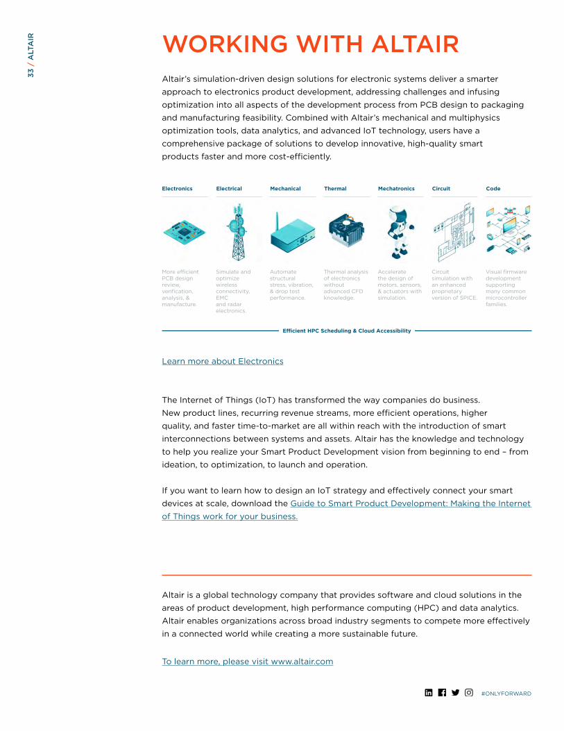
Electronics Electrical Mechanical Thermal Mechatronics Circuit Code
More efficient PCB design review, verification, analysis, & manufacture.
Simulate and optimize wireless connectivity, EMC and radar electronics.
Automate structural stress, vibration, & drop test performance.
Thermal analysis of electronics without advanced CFD knowledge.
Accelerate the design of motors, sensors, & actuators with simulation.
Circuit simulation with an enhanced proprietary version of SPICE.
Visual firmware development supporting many common microcontroller families.
Efficient HPC Scheduling & Cloud Accessibility
WORKING WITH ALTAIRAltair’s simulation-driven design solutions for electronic systems deliver a smarter
approach to electronics product development, addressing challenges and infusing
optimization into all aspects of the development process from PCB design to packaging
and manufacturing feasibility. Combined with Altair’s mechanical and multiphysics
optimization tools, data analytics, and advanced IoT technology, users have a
comprehensive package of solutions to develop innovative, high-quality smart
products faster and more cost-efficiently.
Learn more about Electronics
The Internet of Things (IoT) has transformed the way companies do business.
New product lines, recurring revenue streams, more efficient operations, higher
quality, and faster time-to-market are all within reach with the introduction of smart
interconnections between systems and assets. Altair has the knowledge and technology
to help you realize your Smart Product Development vision from beginning to end – from
ideation, to optimization, to launch and operation.
If you want to learn how to design an IoT strategy and effectively connect your smart
devices at scale, download the Guide to Smart Product Development: Making the Internet
of Things work for your business.