guide to fighting positions, obstacles, and revetments · air force handbook 10-222, volume 14 1...
TRANSCRIPT
AIR FORCE HANDBOOK 10-222, Volume 14 1 NOVEMBER 2000
DEPARTMENT OF THE AIR FORCE
GUIDE TO FIGHTINGPOSITIONS, OBSTACLES,
AND REVETMENTS
Manual Provided by eMilitary Manuals - http://www.emilitarymanuals.com
BY ORDER OF THE AIR FORCE HANDBOOK 10-222, VOLUME 14 SECRETARY OF THE AIR FORCE 1 NOVEMBER 2000
Operations
GUIDE TO FIGHTING POSITIONS, OBSTACLES, AND REVETMENTS NOTICE: This publication is available digitally on the SAF/AFDPO WWW site at: http://afpubs.hq.af.mil. OPR: HQ AFCESA/CEXR (Lt Col Wayland Patterson) Certified by: HQ AFCESA/CEX (Colonel Bruce F. Mc Connell) Pages: 108/Distribution: F Purpose: This handbook addresses the employment and construction of fighting positions, obstacles, and revetments by Civil Engineers. It provides basic concepts for use of fighting positions, obstacles, and revetments as expedient measures to defend against offensive forces and terrorist attack. It may be used at a deployed location, bare base, or at the home station. The defensive measures are primarily intended for protection against conventional weapons blast, fragmentation, and projectiles. INTRODUCTION....................................................................................................... ....................................................................5 GENERAL CONSTRUCTION REQUIREMENTS ............................................. ....................................................................8 PROTECTION REQUIREMENTS.......................................................................... ..................................................................12
Determining Protection Requirements ........................................................... ..................................................................12 Specific Material Choices and Uses................................................................ ..................................................................16 Berm and Revetment Basic Design Considerations..................................... ..................................................................20 Overhead Cover Considerations...................................................................... ..................................................................28
CONSTRUCTION ...................................................................................................... ..................................................................34 Revetments .......................................................................................................... ..................................................................34 Obstacles.............................................................................................................. ..................................................................60 Fighting Positions............................................................................................... ..................................................................85
Figures 1. Historic Earthwork .............................................................................................. ....................................................................5 2. Bracing Concepts................................................................................................. ..................................................................19 3. Containment Concepts........................................................................................ ..................................................................20 4. Sand Berm and Sandbag Revetment ................................................................ ..................................................................21 5. Berm and Revetment Slopes.............................................................................. ..................................................................22 6. Blast Flow over Freestanding Berm................................................................. ..................................................................23 7. Blast Flow over Reinforced Berm .................................................................... ..................................................................24 8. Precast Concrete Revetments/Retaining Walls ............................................... ..................................................................26 9. Sandbags Cut into a Slope.................................................................................. ..................................................................27 10. Blast Flow around Vertical Berms .................................................................... ..................................................................28 11. Stringer Span Distance/On-Center Spacing for Fighting Positions............ ..................................................................30 12. Burster Rock Layer over Hardened Position................................................... ..................................................................33 13. Freestanding Berm Protecting a Fuel Bladder................................................ ..................................................................35 14. Berm against a Building ..................................................................................... ..................................................................35 15. Braced Face of Berm near Building ................................................................. ..................................................................36 16. Freestanding Sloped Sandbag Revetment ....................................................... ..................................................................37 17. Partially Braced Sandbag Revetment ............................................................... ..................................................................38 18. Sandbags against a Structure ............................................................................ ..................................................................39 19. Sandbags Help Support Roof Covering........................................................... ..................................................................39 20. Soil-Cement Wall ................................................................................................ ..................................................................40 21. Bitburg Revetments............................................................................................. ..................................................................41
Manual Provided by eMilitary Manuals - http://www.emilitarymanuals.com
2 AFH 10-222 Volume 14 1 November 2000
22. Four-Meter Aircraft Revetments....................................................................... ..................................................................42 23. Portable Precast Concrete Wall ......................................................................... ..................................................................42 24. Tire Revetment Walls ......................................................................................... ..................................................................43 25. Plywood Walls ..................................................................................................... ..................................................................44 26. B-1 Bin Revetment ............................................................................................. ..................................................................44 27. Dispersed Bin Revetments ................................................................................. ..................................................................45 28. Clustered Bin Revetments.................................................................................. ..................................................................46 29. Timber Revetment ............................................................................................... ..................................................................47 30. Concrete Culvert Soil Bin .................................................................................. ..................................................................48 31. Concrete Chamber Soil Bin ............................................................................... ..................................................................48 32. 55-Gallon Drum Wall ......................................................................................... ..................................................................49 33. Concrete Revetment Soil Bin ............................................................................ ..................................................................50 34. Rock Filled Gabion Walls ...................................................................................................................................................51 35. Sand Grid Revetment ...........................................................................................................................................................52 36. Wire Frame, Fabric-Lined Containers/Concertainer Revetment................. ..................................................................53 37. Berm against a Retaining Wall ...........................................................................................................................................54 38. Partially Braced Berm against a Retaining Wall .............................................................................................................55 39. Berm against a Revetment.....................................................................................................................................................55 40. Landing Mat Shield ................................................................................................................................................................56 41. Log Wall Standoff ..................................................................................................................................................................57 42. Corrugated Metal Wall Shield ..............................................................................................................................................58 43. Fencing Used as Standoff......................................................................................................................................................60 44. Cratering Charge formed Landslide ....................................................................................................................................62 45. Abatis on Forest Road............................................................................................................................................................63 46. Typical Ditch Construction...................................................................................................................................................64 47. Locating Log Hurdles ............................................................................................................................................................65 48. Locating Spoil Mounds..........................................................................................................................................................66 49. Log Hurdles .............................................................................................................................................................................67 50. Staggering Placement of Hurdles.........................................................................................................................................68 51. Log Cribs..................................................................................................................................................................................69 52. Expedient Log Posts ...............................................................................................................................................................70 53. Posts and Entanglements along Roadway ..........................................................................................................................70 54. Placement of Staggered Posts ...............................................................................................................................................71 55. Steel Hedgehogs......................................................................................................................................................................72 56. Metal Caltrops.........................................................................................................................................................................72 57. Concrete Cube and Cylinder.................................................................................................................................................73 58. Concrete Tetrahedron and Dragons Tooth.........................................................................................................................73 59. Rubble Blocking Urban Streets ............................................................................................................................................74 60. Tanglefoot Layout – Example ..............................................................................................................................................75 61. Concertina Wire Roadblock..................................................................................................................................................76 62. Triple Concertina Fence ........................................................................................................................................................77 63. Stopping Capabilities of Obstacles......................................................................................................................................78 64. Straight Faced Curb ................................................................................................................................................................79 65. Cable Reinforced Chain Link Fences .................................................................................................................................80 66. Shallow Ditches and Low Berms and Moguls...................................................................................................................81 67. Jersey Barrier...........................................................................................................................................................................82 68. Placement of Roadway Obstructions ................................................................................................................................82 69. Barrier Spacing versus Automobile Speeds.......................................................................................................................83 70. Typical 4-inch Speed Hump .................................................................................................................................................84 71. Hasty Natural Fighting Position...........................................................................................................................................85 72. Hasty Augmented Fighting Position....................................................................................................................................85 73. Spacing of Bearing Support Beams for Overhead Cover................................................................................................86 74. Facing Material Braced..........................................................................................................................................................87 75. Facing Material Held with Stakes ........................................................................................................................................88
Manual Provided by eMilitary Manuals - http://www.emilitarymanuals.com
AFH 10-222 Volume 14 1 November 2000 3
76. Staggered Stake Bracing of Pickets .....................................................................................................................................89 77. Placement of Ground Shock Intercepting Trenches .........................................................................................................90 78. Typical Grenade Su mps.........................................................................................................................................................91 79. 1-Person Fighting Position (Deliberate) .............................................................................................................................93 80. Straight 2-Person Fighting Position (Deliberate) ..............................................................................................................93 81. Extended 2-Person Fighting Position (Deliberate) ...........................................................................................................94 82. Machine Gun Fighting Position (Deliberate) .....................................................................................................................94 83. Mortar Crew Fighting Position.............................................................................................................................................95 84. LAW Fighting Position (Deliberate)...................................................................................................................................96 85. Wood-Framed Fighting Position..........................................................................................................................................97 86. Precast Concrete Slab Bunker..............................................................................................................................................98 Tables. 1. Characteristics and Use of Fighting Positions, Obstacles, and ........................................................................................6
Revetments 2. General Instruction of Fighting Positions.............................................................................................................................8 3. General Construction of Obstacles ........................................................................................................................................9 4. General Construction of Revetments...................................................................................................................................10 5. Typical Weapons and Their Effects ....................................................................................................................................13 6. Protection from Projectiles for Various Thicknesses of Material ..................................................................................13 7. Protection from Explosions (50 feet away) for Various Thicknesses ...........................................................................15 of Material 8. Expedient Hardening Protection Measure for Assets .......................................................................................................16 9. Relative Protection Levels Measure for Assets .................................................................................................................16 10. Allowable Berm Heights for Conventional Wall Systems ..............................................................................................25 11. Equivalent Sizes of Timber Compared with Dimensional Lumber ...............................................................................29 12. Maximum Span and On-Center Spacing for Stringers.....................................................................................................30 13. Minimum Thickness of Sheathing over Stringers.............................................................................................................31 14. Design Guidelines for Protection from Select Indirect-Fired ........................................................................................31 Munitions (Contact Fuze) 15. Required Thickness of Cover for Protection against Indirect and ................................................................................32 Direct-Fired Weapons (Delayed Fuze) Attachments 1. Arrangement Patterns for Revetments and Berms ............................................................................................................99 2. Tests for Field Classification of Soil.................................................................................................................................102
Manual Provided by eMilitary Manuals - http://www.emilitarymanuals.com

4 AFH 10-222 Volume 14 1 November 2000
THIS PAGE INTENTIONALLY LEFT BLANK.
Manual Provided by eMilitary Manuals - http://www.emilitarymanuals.com
AFH 10-222 Volume 14 1 November 2000 5
INTRODUCTION
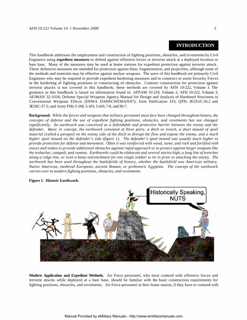
This handbook addresses the employment and construction of fighting positions, obstacles, and revetments by Civil Engineers using expedient measures to defend against offensive forces or terrorist attack at a deployed location or bare base. Many of the measures may be used at home stations for expedient protection against terrorist attack. These defensive measures are intended for protection against blast, fragmentation, and projectiles, although some of the methods and materials may be effective against nuclear weapons. The users of this handbook are primarily Civil Engineers who may be required to provide expedient hardening measures and to construct or assist Security Forces in the hardening of fighting positions or constructing of obstacles. Contract construction for protection against terrorist attacks is not covered in this handbook; these methods are covered by AFH 10-222, Volume 3. The guidance in this handbook is based on information found in: AFPAM 10-219, Volume 2; AFH 10-222, Volume 3; AFJMAN 32-1034; Defense Special Weapons Agency Manual for Design and Analysis of Hardened Structures to Conventional Weapons Effects (DSWA DAHSCWEMAN-97); Joint Publication 3-15; QTPs 3E2X1C-26.2 and 3E3XC-37.5; and Army FMs 5-100, 5-103, 5-410, 7-8, and 90-7. Background. While the forces and weapons that military personnel must face have changed throughout history, the concepts of defense and the use of expedient fighting positions, obstacles, and revetments has not changed significantly. An earthwork was conceived as a defendable and protective barrier between the enemy and the defender. Basic in concept, the earthwork consisted of three parts: a ditch or trench, a short mound of spoil material (called a parapet) on the enemy side of the ditch to disrupt the flow and expose the enemy, and a much higher spoil mound on the defender’s side (figure 1). The defender’s spoil mound was usually much higher to provide protection for defense and movement. Often it was reinforced with wood, stone, and rock and fortified with staves and stakes to provide additional obstacles against rapid approach or to protect against larger weapons like the trebuchet, catapult, and cannon. Earthworks could be elaborate and several stories high, a long line of trenches along a ridge line, or even a hasty entrenchment for one single soldier to lie in prior to attacking the enemy. The earthwork has been used throughout the battlefields of history, whether the battlefield was American military, Native American, medieval European, ancient Roman, or prehistoric Egyptian. The concept of the earthwork carries over to modern fighting positions, obstacles, and revetments. Figure 1. Historic Earthwork.
Modern Application and Expedient Methods. Air Force personnel, who must contend with offensive forces and terrorist attacks while deployed at a bare base, should be familiar with the basic construction requirements for fighting positions, obstacles, and revetments. Air Force personnel at their home station, if they have to contend with
Manual Provided by eMilitary Manuals - http://www.emilitarymanuals.com
6 AFH 10-222 Volume 14 1 November 2000
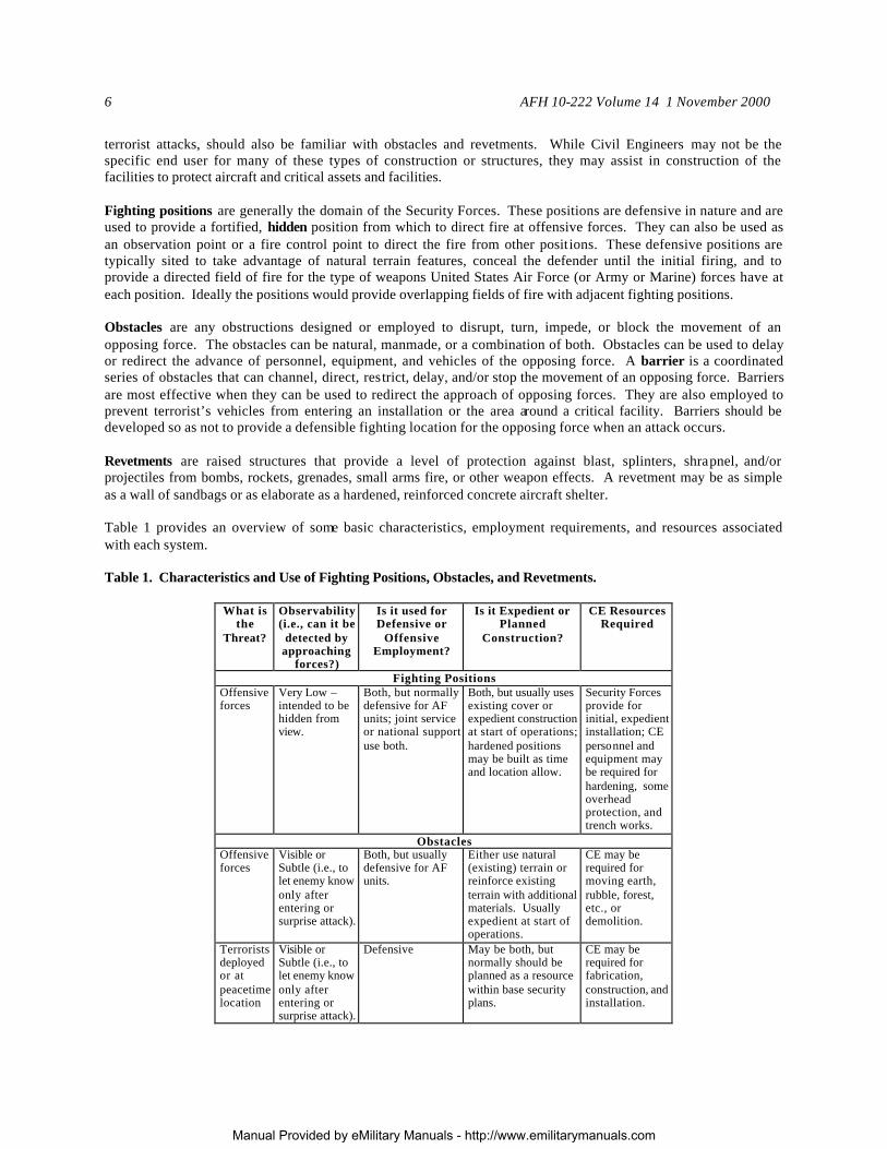
terrorist attacks, should also be familiar with obstacles and revetments. While Civil Engineers may not be the specific end user for many of these types of construction or structures, they may assist in construction of the facilities to protect aircraft and critical assets and facilities. Fighting positions are generally the domain of the Security Forces. These positions are defensive in nature and are used to provide a fortified, hidden position from which to direct fire at offensive forces. They can also be used as an observation point or a fire control point to direct the fire from other positions. These defensive positions are typically sited to take advantage of natural terrain features, conceal the defender until the initial firing, and to provide a directed field of fire for the type of weapons United States Air Force (or Army or Marine) forces have at each position. Ideally the positions would provide overlapping fields of fire with adjacent fighting positions. Obstacles are any obstructions designed or employed to disrupt, turn, impede, or block the movement of an opposing force. The obstacles can be natural, manmade, or a combination of both. Obstacles can be used to delay or redirect the advance of personnel, equipment, and vehicles of the opposing force. A barrier is a coordinated series of obstacles that can channel, direct, restrict, delay, and/or stop the movement of an opposing force. Barriers are most effective when they can be used to redirect the approach of opposing forces. They are also employed to prevent terrorist’s vehicles from entering an installation or the area around a critical facility. Barriers should be developed so as not to provide a defensible fighting location for the opposing force when an attack occurs. Revetments are raised structures that provide a level of protection against blast, splinters, shrapnel, and/or projectiles from bombs, rockets, grenades, small arms fire, or other weapon effects. A revetment may be as simple as a wall of sandbags or as elaborate as a hardened, reinforced concrete aircraft shelter. Table 1 provides an overview of some basic characteristics, employment requirements, and resources associated with each system. Table 1. Characteristics and Use of Fighting Positions, Obstacles, and Revetments.
What is the
Threat?
Observability (i.e., can it be
detected by approaching
forces?)
Is it used for Defensive or
Offensive Employment?
Is it Expedient or Planned
Construction?
CE Resources Required
Fighting Positions Offensive forces
Very Low – intended to be hidden from view.
Both, but normally defensive for AF units; joint service or national support use both.
Both, but usually uses existing cover or expedient construction at start of operations; hardened positions may be built as time and location allow.
Security Forces provide for initial, expedient installation; CE personnel and equipment may be required for hardening, some overhead protection, and trench works.
Obstacles Offensive forces
Visible or Subtle (i.e., to let enemy know only after entering or surprise attack).
Both, but usually defensive for AF units.
Either use natural (existing) terrain or reinforce existing terrain with additional materials. Usually expedient at start of operations.
CE may be required for moving earth, rubble, forest, etc., or demolition.
Terrorists deployed or at peacetime location
Visible or Subtle (i.e., to let enemy know only after entering or surprise attack).
Defensive May be both, but normally should be planned as a resource within base security plans.
CE may be required for fabrication, construction, and installation.
Manual Provided by eMilitary Manuals - http://www.emilitarymanuals.com
AFH 10-222 Volume 14 1 November 2000 7
What is the
Threat?
Observability (i.e., can it be
detected by approaching
forces?)
Is it used for Defensive or
Offensive Employment?
Is it Expedient or Planned
Construction?
CE Resources Required
Revetments Offensive forces
Medium to Low Defensive Both, especially if berms are used.
High CE involvement for construction and installation, but manpower efforts may be basewide for hasty.
Terrorists when deployed or at peacetime station.
Usually High Defensive Both but should be pre-planned at peacetime stations when possible.
High CE involvement for construction and installation; manpower efforts may be basewide.
Manual Provided by eMilitary Manuals - http://www.emilitarymanuals.com
8 AFH 10-222 Volume 14 1 November 2000
GENERAL CONSTRUCTION
REQUIREMENT This chapter provides a preview on the use and construction for fighting positions, obstacles, and revetments. It introduces terminology that is used throughout the discussion for determining use, protection requirements, and construction. Construction of Fighting Positions. Fighting positions protect personnel by providing cover through use of existing materials or construction of physical barriers or obstacles. They also provide concealment through positioning and proper camouflage. The position should not be readily identifiable by an opposing force. When possible, fighting positions should be sited in non-obvious places, such as behind natural cover, and should be easily camouflaged. Basic criteria for fighting positions are detailed in Table 2 and below:
The positions should be armpit deep. The positions may require shallower ledges along the inside perimeter of the position to allow placing of weapons or bracing for aiming of weapons, depending on weapons employed. Ensure that the position has stable construction:
Brace/revet excavations in sandy or unstable soil and Check stabilization of wall bases.
Provide for grenade sumps; slope the interior ground/floor surface toward the sumps.
Inspect and test the position daily, after heavy rain, and after receiving weapons fire. Maintain, repair, and improve positions as required. Use proper material. Use it correctly.
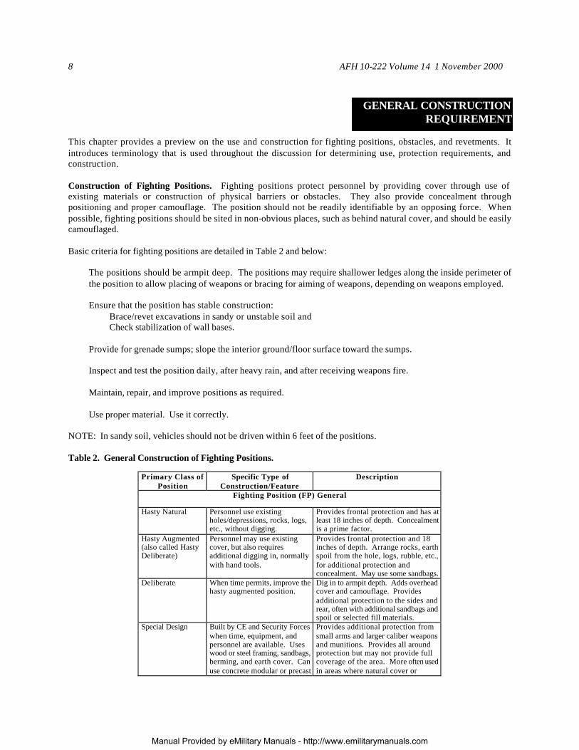
NOTE: In sandy soil, vehicles should not be driven within 6 feet of the positions. Table 2. General Construction of Fighting Positions.
Primary Class of Position
Specific Type of Construction/Feature
Description
Fighting Position (FP) General
Hasty Natural Personnel use existing holes/depressions, rocks, logs, etc., without digging.
Provides frontal protection and has at least 18 inches of depth. Concealment is a prime factor.
Hasty Augmented (also called Hasty Deliberate)
Personnel may use existing cover, but also requires additional digging in, normally with hand tools.
Provides frontal protection and 18 inches of depth. Arrange rocks, earth spoil from the hole, logs, rubble, etc., for additional protection and concealment. May use some sandbags.
Deliberate When time permits, improve the hasty augmented position.
Dig in to armpit depth. Adds overhead cover and camouflage. Provides additional protection to the sides and rear, often with additional sandbags and spoil or selected fill materials.
Special Design Built by CE and Security Forces when time, equipment, and personnel are available. Uses wood or steel framing, sandbags, berming, and earth cover. Can use concrete modular or precast concrete revetment sections for
Provides additional protection from small arms and larger caliber weapons and munitions. Provides all around protection but may not provide full coverage of the area. More often used in areas where natural cover or protection is lacking.
Manual Provided by eMilitary Manuals - http://www.emilitarymanuals.com
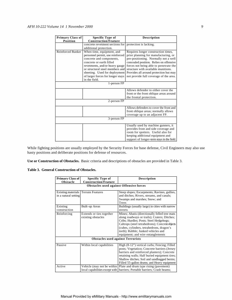
AFH 10-222 Volume 14 1 November 2000 9
Primary Class of Position
Specific Type of Construction/Feature
Description
concrete revetment sections for additional protection.
protection is lacking.
Reinforced Bunker When time, equipment, and personnel permit, use reinforced concrete and components, concrete or earth filled revetments, and/or heavy gauge or structural steel members and sheeting. Used for deployment of larger forces for longer stays in the field.
Requires longer construction times, prior planning for manufacturing, or pre-positioning. Normally not a well concealed position. Relies on offensive forces not being able to penetrate the structure with available munitions. Provides all around protection but may not provide full coverage of the area.
1-person FP
Allows defender to either cover the front or the front oblique areas around the frontal protection.
2-person FP
Allows defenders to cover the front and front oblique areas; normally allows coverage up to an adjacent FP.
3-person FP
Usually used by machine gunners, it provides front and side coverage and room for spotters. Useful also for keeping addit ional equipment and support of longer-term stays in the field.
While fighting positions are usually employed by the Security Forces for base defense, Civil Engineers may also use hasty positions and deliberate positions for defense of resources. Use or Construction of Obstacles. Basic criteria and descriptions of obstacles are provided in Table 3. Table 3. General Construction of Obstacles.
Primary Class of Obstacle
Specific Type of Construction/Feature
Description
Obstacles used against Offensive forces
Existing materials in a natural setting
Terrain Features Steep slopes; Escarpments; Ravines, gullies, and ditches; Rivers, streams, and canals; Swamps and marshes; Snow; and Trees
Existing construction
Built-up Areas Buildings (usually large) in cities with narrow streets
Reinforcing Extends or ties together existing obstacles
Mines; Abatis (directionally felled tree mats along roadways or trails); Craters; Ditches; Cribs; Hurdles; Posts; Steel Hedgehogs; Caltrops (steel tetrahedrons); Concrete objects (cubes, cylinders, tetrahedrons, dragon’s teeth); Rubble; Junked vehicles and equipment; and wire entanglements
Obstacles used against Terrorists
Passive Within local capabilities High (8-12”) vertical curbs; Fencing; Filled posts; Vegetation; Concrete barriers (Jersey barriers and reinforced planters); Concrete retaining walls; Half buried equipment tires; Shallow ditches; Soil and sandbagged berms; Filled 55-gallon drums; and Heavy equipment
Active Vehicle (may not be within local capabilities except with contract support)
Plate and drum type rising (pavement) barriers; Portable barriers; Crash beams; Sliding crash gates; and Cable and beam
Manual Provided by eMilitary Manuals - http://www.emilitarymanuals.com